Service Procedures for 1955-56 Power Antenna
13
Service Procedures for 1955-56 Pontiac Power Antenna By Bob Johnson, editing and "webizing" by Larry Gorden May 2011 This article describes service procedures for the 1956 power antenna. There may be minor differences in service instructions for other year Casco antennas. Introduction & General Nomenclature: The Casco power antenna option, as available for all 1955-56 Pontiacs (and Casco equipped „57‟s), is a relatively easy to maintain accessory that proved quite durable under normal usage. The power antenna used for all ‟55 models and for all Station Wagon models in ‟56 are referred to hereinafter as Type I. The power antenna used for all other models in ‟56 (and ‟57) is referred to hereinafter as Type II. The typical power antenna assembly consists of various subcomponents as follows: 1) The antenna motor and case (Type I used 2 short power leads each with a rubber boot; Type II used a long “siamese wire” power lead); 2) The drive assembly and its upper housing; 3) The upper antenna mast tube with insulator, grommet, adapter and nut; 4) The mast lead storage tube (Type I used a shaped aluminum tube that was clamped to the upper mast tube; Type II used a nylon tube); 5) The mast assembly (although two types of masts have been identified, they are both interchangeable in either a Type I or Type II power antenna assembly); and, 6) The antenna lead (Type I with a rubber boot; Type II equipped without a rubber boot). The differences between the two power antenna unit types are primarily related to the routing of the power and antenna leads (i.e. interior vs. exterior). All models in ‟55 and all station wagon models in ‟56 (& Casco equipped wagons in 57) routed both power and antenna leads externally from the cowl along the outer frame rail to the antenna location under the right hand rear fender. All other models in ‟56 (& non-wagon Casco equipped models in „57) routed the antenna and power leads through the interior of the car into the trunk, and then out through a rubber grommet to under the right hand rear fender.
Transcript of Service Procedures for 1955-56 Power Antenna

Service Procedures for
1955-56 Pontiac Power Antenna By Bob Johnson, editing and "webizing" by Larry Gorden
May 2011
This article describes service procedures for the 1956 power antenna. There may be minor differences
in service instructions for other year Casco antennas.
Introduction & General Nomenclature:
The Casco power antenna option, as available for all 1955-56 Pontiacs (and Casco equipped „57‟s), is a
relatively easy to maintain accessory that proved quite durable under normal usage. The power
antenna used for all ‟55 models and for all Station Wagon models in ‟56 are referred to hereinafter as
Type I. The power antenna used for all other models in ‟56 (and ‟57) is referred to hereinafter as
Type II.
The typical power antenna assembly consists of various subcomponents as follows:
1) The antenna motor and case (Type I used 2 short power leads each with a rubber boot; Type II
used a long “siamese wire” power lead);
2) The drive assembly and its upper housing;
3) The upper antenna mast tube with insulator, grommet, adapter and nut;
4) The mast lead storage tube (Type I used a shaped aluminum tube that was clamped to the upper
mast tube; Type II used a nylon tube);
5) The mast assembly (although two types of masts have been identified, they are both
interchangeable in either a Type I or Type II power antenna assembly); and,
6) The antenna lead (Type I with a rubber boot; Type II equipped without a rubber boot).
The differences between the two power antenna unit types are primarily related to the routing of the
power and antenna leads (i.e. interior vs. exterior). All models in ‟55 and all station wagon models in
‟56 (& Casco equipped wagons in 57) routed both power and antenna leads externally from the cowl
along the outer frame rail to the antenna location under the right hand rear fender. All other models in
‟56 (& non-wagon Casco equipped models in „57) routed the antenna and power leads through the
interior of the car into the trunk, and then out through a rubber grommet to under the right hand rear
fender.
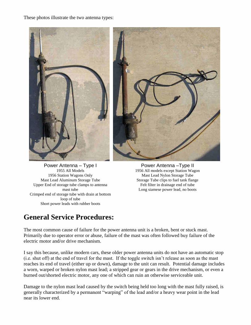
These photos illustrate the two antenna types:
Power Antenna – Type I 1955 All Models
1956 Station Wagons Only
Mast Lead Aluminum Storage Tube
Upper End of storage tube clamps to antenna
mast tube
Crimped end of storage tube with drain at bottom
loop of tube
Short power leads with rubber boots
Power Antenna –Type II 1956 All models except Station Wagon
Mast Lead Nylon Storage Tube
Storage Tube clips to fuel tank flange
Felt filter in drainage end of tube
Long siamese power lead, no boots
General Service Procedures:
The most common cause of failure for the power antenna unit is a broken, bent or stuck mast.
Primarily due to operator error or abuse, failure of the mast was often followed buy failure of the
electric motor and/or drive mechanism.
I say this because, unlike modern cars, these older power antenna units do not have an automatic stop
(i.e. shut off) at the end of travel for the mast. If the toggle switch isn‟t release as soon as the mast
reaches its end of travel (either up or down), damage to the unit can result. Potential damage includes
a worn, warped or broken nylon mast lead; a stripped gear or gears in the drive mechanism, or even a
burned out/shorted electric motor, any one of which can ruin an otherwise serviceable unit.
Damage to the nylon mast lead caused by the switch being held too long with the mast fully raised, is
generally characterized by a permanent “warping” of the lead and/or a heavy wear point in the lead
near its lower end.
By contrast, damage to the nylon mast lead caused by the switch being held too long with the mast
fully lowered is characterized by stripped gears, a badly worn spot at the nylon leads upper end, or
even a broken lead. Worn spots in the nylon lead can result in the mast not travelling either up or
down past the worn spot. It just slips unless the adjustment screw and spring tension is increased.
However, increasing the tension on the drive mechanism can cause undue wear and tear on the drive
unit and its gears, accelerate wear on the lead, and can even cause the nylon lead to break if the mast is
lowered and the switch is not promptly released. The thin worn spot in the lead simply snaps. That‟s
the end of that mast!
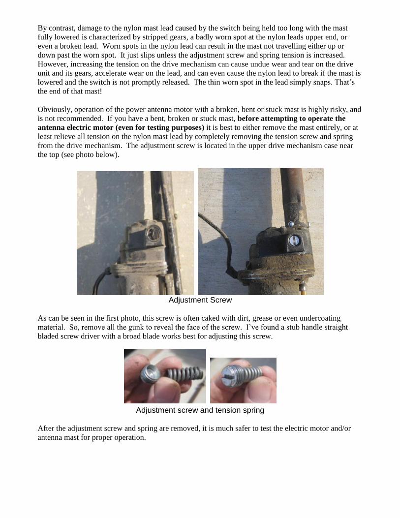
Obviously, operation of the power antenna motor with a broken, bent or stuck mast is highly risky, and
is not recommended. If you have a bent, broken or stuck mast, before attempting to operate the
antenna electric motor (even for testing purposes) it is best to either remove the mast entirely, or at
least relieve all tension on the nylon mast lead by completely removing the tension screw and spring
from the drive mechanism. The adjustment screw is located in the upper drive mechanism case near
the top (see photo below).
Adjustment Screw
As can be seen in the first photo, this screw is often caked with dirt, grease or even undercoating
material. So, remove all the gunk to reveal the face of the screw. I‟ve found a stub handle straight
bladed screw driver with a broad blade works best for adjusting this screw.
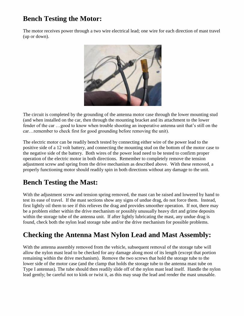
Adjustment screw and tension spring
After the adjustment screw and spring are removed, it is much safer to test the electric motor and/or
antenna mast for proper operation.
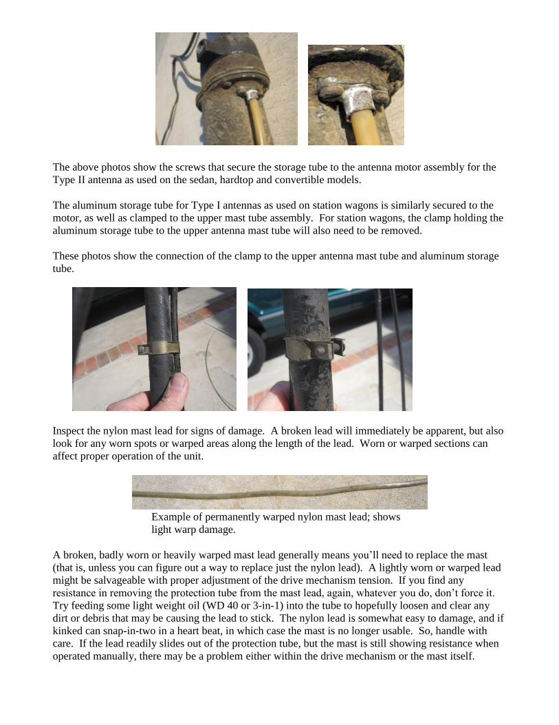
Bench Testing the Motor:
The motor receives power through a two wire electrical lead; one wire for each direction of mast travel
(up or down).
The circuit is completed by the grounding of the antenna motor case through the lower mounting stud
(and when installed on the car, then through the mounting bracket and its attachment to the lower
fender of the car …good to know when trouble shooting an inoperative antenna unit that‟s still on the
car…remember to check first for good grounding before removing the unit).
The electric motor can be readily bench tested by connecting either wire of the power lead to the
positive side of a 12 volt battery, and connecting the mounting stud on the bottom of the motor case to
the negative side of the battery. Both wires of the power lead need to be tested to confirm proper
operation of the electric motor in both directions. Remember to completely remove the tension
adjustment screw and spring from the drive mechanism as described above. With these removed, a
properly functioning motor should readily spin in both directions without any damage to the unit.
Bench Testing the Mast:
With the adjustment screw and tension spring removed, the mast can be raised and lowered by hand to
test its ease of travel. If the mast sections show any signs of undue drag, do not force them. Instead,
first lightly oil them to see if this relieves the drag and provides smoother operation. If not, there may
be a problem either within the drive mechanism or possibly unusually heavy dirt and grime deposits
within the storage tube of the antenna unit. If after lightly lubricating the mast, any undue drag is
found, check both the nylon lead storage tube and/or the drive mechanism for possible problems.
Checking the Antenna Mast Nylon Lead and Mast Assembly:
With the antenna assembly removed from the vehicle, subsequent removal of the storage tube will
allow the nylon mast lead to be checked for any damage along most of its length (except that portion
remaining within the drive mechanism). Remove the two screws that hold the storage tube to the
lower side of the motor case (and the clamp that holds the storage tube to the antenna mast tube on
Type I antennas). The tube should then readily slide off of the nylon mast lead itself. Handle the nylon
lead gently; be careful not to kink or twist it, as this may snap the lead and render the mast unusable.
The above photos show the screws that secure the storage tube to the antenna motor assembly for the
Type II antenna as used on the sedan, hardtop and convertible models.
The aluminum storage tube for Type I antennas as used on station wagons is similarly secured to the
motor, as well as clamped to the upper mast tube assembly. For station wagons, the clamp holding the
aluminum storage tube to the upper antenna mast tube will also need to be removed.
These photos show the connection of the clamp to the upper antenna mast tube and aluminum storage
tube.
Inspect the nylon mast lead for signs of damage. A broken lead will immediately be apparent, but also
look for any worn spots or warped areas along the length of the lead. Worn or warped sections can
affect proper operation of the unit.
Example of permanently warped nylon mast lead; shows
light warp damage.
A broken, badly worn or heavily warped mast lead generally means you‟ll need to replace the mast
(that is, unless you can figure out a way to replace just the nylon lead). A lightly worn or warped lead
might be salvageable with proper adjustment of the drive mechanism tension. If you find any
resistance in removing the protection tube from the mast lead, again, whatever you do, don‟t force it.
Try feeding some light weight oil (WD 40 or 3-in-1) into the tube to hopefully loosen and clear any
dirt or debris that may be causing the lead to stick. The nylon lead is somewhat easy to damage, and if
kinked can snap-in-two in a heart beat, in which case the mast is no longer usable. So, handle with
care. If the lead readily slides out of the protection tube, but the mast is still showing resistance when
operated manually, there may be a problem either within the drive mechanism or the mast itself.
Checking the Drive Mechanism:
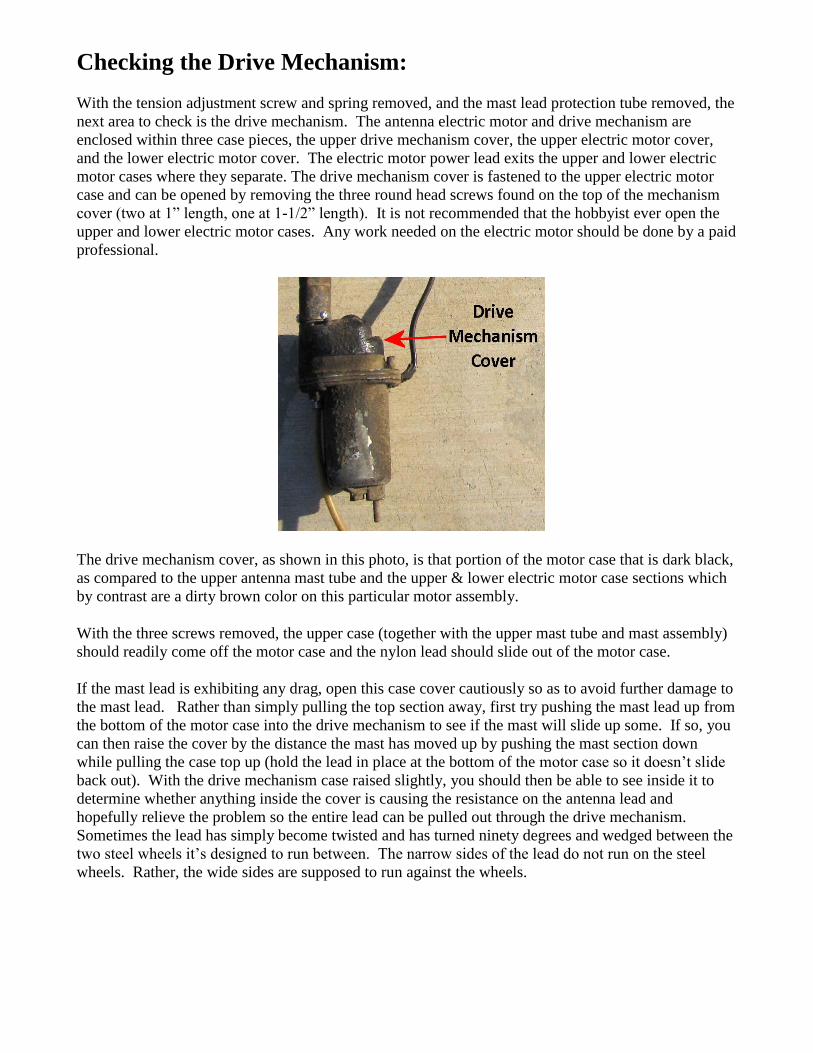
With the tension adjustment screw and spring removed, and the mast lead protection tube removed, the
next area to check is the drive mechanism. The antenna electric motor and drive mechanism are
enclosed within three case pieces, the upper drive mechanism cover, the upper electric motor cover,
and the lower electric motor cover. The electric motor power lead exits the upper and lower electric
motor cases where they separate. The drive mechanism cover is fastened to the upper electric motor
case and can be opened by removing the three round head screws found on the top of the mechanism
cover (two at 1” length, one at 1-1/2” length). It is not recommended that the hobbyist ever open the
upper and lower electric motor cases. Any work needed on the electric motor should be done by a paid
professional.
The drive mechanism cover, as shown in this photo, is that portion of the motor case that is dark black,
as compared to the upper antenna mast tube and the upper & lower electric motor case sections which
by contrast are a dirty brown color on this particular motor assembly.
With the three screws removed, the upper case (together with the upper mast tube and mast assembly)
should readily come off the motor case and the nylon lead should slide out of the motor case.
If the mast lead is exhibiting any drag, open this case cover cautiously so as to avoid further damage to
the mast lead. Rather than simply pulling the top section away, first try pushing the mast lead up from
the bottom of the motor case into the drive mechanism to see if the mast will slide up some. If so, you
can then raise the cover by the distance the mast has moved up by pushing the mast section down
while pulling the case top up (hold the lead in place at the bottom of the motor case so it doesn‟t slide
back out). With the drive mechanism case raised slightly, you should then be able to see inside it to
determine whether anything inside the cover is causing the resistance on the antenna lead and
hopefully relieve the problem so the entire lead can be pulled out through the drive mechanism.
Sometimes the lead has simply become twisted and has turned ninety degrees and wedged between the
two steel wheels it‟s designed to run between. The narrow sides of the lead do not run on the steel
wheels. Rather, the wide sides are supposed to run against the wheels.
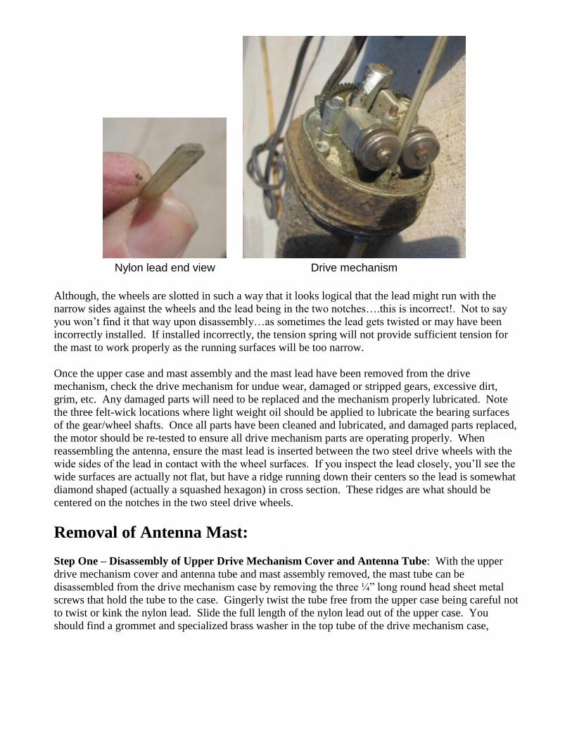
Nylon lead end view Drive mechanism
Although, the wheels are slotted in such a way that it looks logical that the lead might run with the
narrow sides against the wheels and the lead being in the two notches….this is incorrect!. Not to say
you won‟t find it that way upon disassembly…as sometimes the lead gets twisted or may have been
incorrectly installed. If installed incorrectly, the tension spring will not provide sufficient tension for
the mast to work properly as the running surfaces will be too narrow.
Once the upper case and mast assembly and the mast lead have been removed from the drive
mechanism, check the drive mechanism for undue wear, damaged or stripped gears, excessive dirt,
grim, etc. Any damaged parts will need to be replaced and the mechanism properly lubricated. Note
the three felt-wick locations where light weight oil should be applied to lubricate the bearing surfaces
of the gear/wheel shafts. Once all parts have been cleaned and lubricated, and damaged parts replaced,
the motor should be re-tested to ensure all drive mechanism parts are operating properly. When
reassembling the antenna, ensure the mast lead is inserted between the two steel drive wheels with the
wide sides of the lead in contact with the wheel surfaces. If you inspect the lead closely, you‟ll see the
wide surfaces are actually not flat, but have a ridge running down their centers so the lead is somewhat
diamond shaped (actually a squashed hexagon) in cross section. These ridges are what should be
centered on the notches in the two steel drive wheels.
Removal of Antenna Mast:
Step One – Disassembly of Upper Drive Mechanism Cover and Antenna Tube: With the upper
drive mechanism cover and antenna tube and mast assembly removed, the mast tube can be
disassembled from the drive mechanism case by removing the three ¼” long round head sheet metal
screws that hold the tube to the case. Gingerly twist the tube free from the upper case being careful not
to twist or kink the nylon lead. Slide the full length of the nylon lead out of the upper case. You
should find a grommet and specialized brass washer in the top tube of the drive mechanism case,

and another mating grommet in the lower end of the antenna tube.
This antenna mast is a replacement type, and differs slightly from the original equipment
mast. The base of an original mast has two square tabs 180 degrees apart that mate to the two
notches in the brass washer that seats in the grommet found in the drive mechanism case.
Carefully note their relative positions, and how the brass washer mates to the bottom of the antenna
mast. Both grommets and the washer should be removed, cleaned and waxed in preparation for
reassembly of the mast. Do not attempt to remove the mast assembly from the antenna tube before
disconnecting the antenna lead wire.
Step Two – Antenna Cable Lead Removal: Remove the antenna cable lead from the upper antenna
tube. There are a couple of ways this can be done. The antenna lead is attached to a special bracket on
the upper tube by a fine threaded screw collar. This collar is an aluminum piece, and the bracket to
which it is attached is a steel bracket.
Aluminum collar Steel bracket

Consequently, due to corrosion problems associated with dissimilar metals, the screw collar does not
always come off readily. Additionally, because of its fine threads, dirt and grime can bind the two
together to the point they cannot be unscrewed. A liberal application of liquid wrench/WD 40 is
usually helpful, but be careful not exert too much force on this collar, as the aluminum threads often
strip out easily. If you are successful in unscrewing the aluminum collar, you can disconnect the
antenna lead from the lead plug. If you find you cannot unscrew the collar, then go to Plan B below.
Step Three – Antenna Lead Bracket and Pin Removal: The antenna lead bracket is fastened to the
antenna tube with two ¼” long round head metal screws, and a cork gasket seals the joint between the
bracket and the tube. Remove the two screws and gingerly pry the bracket loose from around the
antenna lead pin. The lead pin is held in place by a rubber gasket that is a press fit into the hole in the
antenna mast tube which keeps the pin centered in the bracket. Once the bracket is removed, this
rubber gasket and pin can be worked out of the press fit hole in the antenna tube. The pin itself is
attached to a small washer held within the rubber gasket. I‟ve never been successful in getting the
washer and pin out of the gasket. The pin is also soldered to a very fine multi-strand wire the other end
of which is in turn soldered to the outer-most antenna mast telescoping tube. The wire connecting the
pin to the mast tube is very short. In past efforts to unsolder the wire from the antenna pin, I‟ve found
the rubber gasket often melts before the solder connecting the wire to the pin. So, typically once I pry
the rubber grommet and pin out of the antenna tube, I will carefully cut the connecting wire, leaving
sufficient length attached to the pin so a splice can be made and soldered to a new connecting wire
between the pin and replaced mast.
Pin and grommet in place Pin and grommet
spliced to new mast lead
Step Four – Plan B: If you cannot unscrew the collar from the bracket, a second way of removing the
antenna lead cable is to simply unscrew the two sheet metal screws that hold the steel bracket to the
upper tube. Then, carefully gently pry the bracket from the tube so the gasket and pin are visible. This
effectively unplugs the lead from the pin with the bracket still attached to the collar. Next, cut the pin
lead wire as described above.
Step Five - Plan C: Rather than cutting the pin lead wire; if you have a small enough soldering iron
and a steady hand, you can instead unsolder the wire from the antenna mast by working through the
very tiny hole in the outer antenna tube. Reassembly could then be done either by re-soldering the pin
lead wire directly to the mast tube, again working through the tiny tube hole, or by soldering a new
longer wire to the mast tube of sufficient length to allow the new wire to be spliced to the old with the
splice made outside the outer antenna tube. The excess wire length can then be stuffed back inside
tube. If you elect to cut the wire, be sure to leave a sufficient length of wire on each end so the wires
can either be spliced back together or a new wire can be soldered to the replacement/refinished mast
and spliced to the old wire on the antenna lead pin.
Step Six – Removing the Mast Assembly: Now that you‟ve successfully disconnected the antenna
lead pin, the mast assembly can be removed from the upper antenna tube by removing the grommet at
the top of the tube, and then sliding the antenna mast down through the lower grommet at the bottom
of the antenna tube. The lower grommet has four half circle holes surrounding the center hole through
which the small bump of solder on the mast and the remaining length of antenna lead pin wire can slip
through if you align them properly. Once the mast is removed, this lower grommet is much easier to
remove from the antenna tube. The upper grommet should likewise be thoroughly cleaned and waxed
as was done for both lower grommets in preparation for reassembly.
Step Seven – Replating the Mast: If the mast needs new chrome plating, it‟s best to disassemble the
entire assembly into its five segments before attempting to refinish it. Be sure to advise your plating
company that all pieces must telescope together after plating. They need to avoid coating them with
too much plating such that they bind or will no longer fit together at all. Even a small amount of
additional drag can easily snap the nylon operating lead, so you really have to be careful here. The
mast segments should be flash plated only….and a section of the largest tube, where the antenna lead
is soldered to the mast must be kept clean of any chrome so the lead wire can be re-soldered to the
copper under plating. If your antenna mast needs to be replated, it can be further disassembled as
follows:
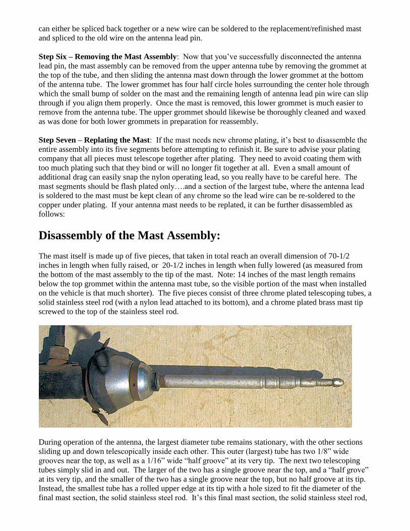
Disassembly of the Mast Assembly:
The mast itself is made up of five pieces, that taken in total reach an overall dimension of 70-1/2
inches in length when fully raised, or 20-1/2 inches in length when fully lowered (as measured from
the bottom of the mast assembly to the tip of the mast. Note: 14 inches of the mast length remains
below the top grommet within the antenna mast tube, so the visible portion of the mast when installed
on the vehicle is that much shorter). The five pieces consist of three chrome plated telescoping tubes, a
solid stainless steel rod (with a nylon lead attached to its bottom), and a chrome plated brass mast tip
screwed to the top of the stainless steel rod.
During operation of the antenna, the largest diameter tube remains stationary, with the other sections
sliding up and down telescopically inside each other. This outer (largest) tube has two 1/8” wide
grooves near the top, as well as a 1/16” wide “half groove” at its very tip. The next two telescoping
tubes simply slid in and out. The larger of the two has a single groove near the top, and a “half grove”
at its very tip, and the smaller of the two has a single groove near the top, but no half groove at its tip.
Instead, the smallest tube has a rolled upper edge at its tip with a hole sized to fit the diameter of the
final mast section, the solid stainless steel rod. It‟s this final mast section, the solid stainless steel rod,
to which a nylon lead is fastened and which feeds through the drive mechanism, which raises and
lowers the antenna mast assembly.
At its upper end a chrome plated brass tip screws on to the rod which keeps it from being pulled down
too far when the antenna mast is lowered, essentially serving as a mechanical stop. Again, since there
is no automatic stop of the antenna mast‟s travel, as on newer cars, if the operator continues to hold the
power antenna toggle switch after the mast reaches its end of travel, damage can occur to the drive
mechanism gears, nylon lead and/or electric motor. There is no noticeable change in the motor noise
coming from the antenna assembly when the mast reaches its end of travel. Consequently, it is best if
the antenna is only operated when the operator can clearly see the position of the mast.
To disassemble the mast assembly, first remove the mast tip by unscrewing it from the tip of the
uppermost mast section, the stainless steel rod.
A small crescent wrench on the tip and a pair of vise grips on the rod will usually accomplish this task
without damage to either part. Once the tip is removed from the stainless rod, the rod can be slid out
of the mast assembly and the remaining tubes should readily slid apart as well.
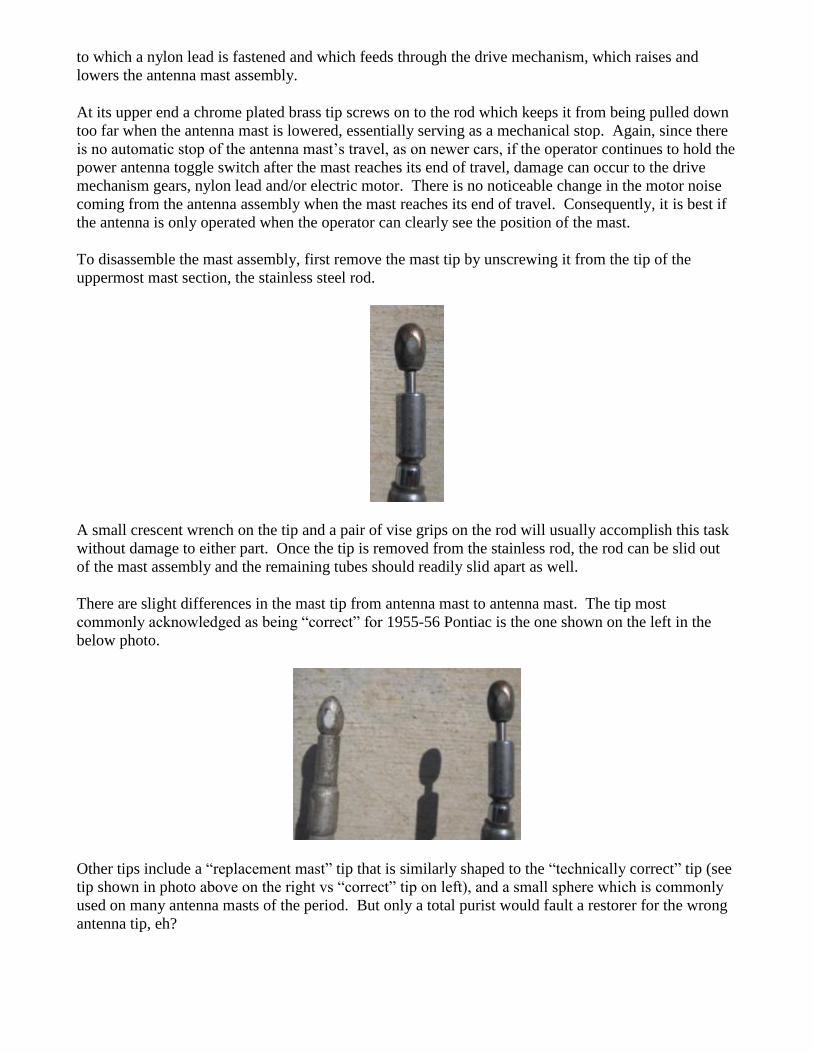
There are slight differences in the mast tip from antenna mast to antenna mast. The tip most
commonly acknowledged as being “correct” for 1955-56 Pontiac is the one shown on the left in the
below photo.
Other tips include a “replacement mast” tip that is similarly shaped to the “technically correct” tip (see
tip shown in photo above on the right vs “correct” tip on left), and a small sphere which is commonly
used on many antenna masts of the period. But only a total purist would fault a restorer for the wrong
antenna tip, eh?
Reassembly, Lubrication and Adjustment:
To reassemble the power antenna, simply assemble in reverse order of the above disassembly
instructions.
Assemble the antenna mast pieces after plating (use a high grade metal polish on the stainless steel
mast rod), lightly oiling the sections to ensure the telescope smoothly without binding. Screw the
replated mast tip back onto the stainless steel rod to secure the mast assembly.
Slide the lower tube grommet over the reassembled mast assembly and reinstall the mast assembly &
lower grommet into the upper antenna tube. Resolder the antenna lead pin to the mast. Push any
excess lead wire back inside the tube and reinstall the lead pin and grommet in the antenna tube hole.
Reinstall the lead pin bracket and antenna lead with a new cork gasket. Reinstall the upper antenna
tube grommet.
Reinstall the tube grommet in the drive mechanism upper case, aligning both the specialized brass
washer and grommet to mate properly with the lower grommet in the antenna tube. Slide the nylon
mast lead down through the tube grommet in the upper drive mechanism case and replace the 3 screws
holding the antenna tube to the upper case cover.
Slide the antenna nylon lead through the two steel drive wheels in the drive mechanism, ensuring the
wide sides of the lead are in contact with and centered between the two drive wheels. Slip the upper
case in place and reinstall the three case screws.
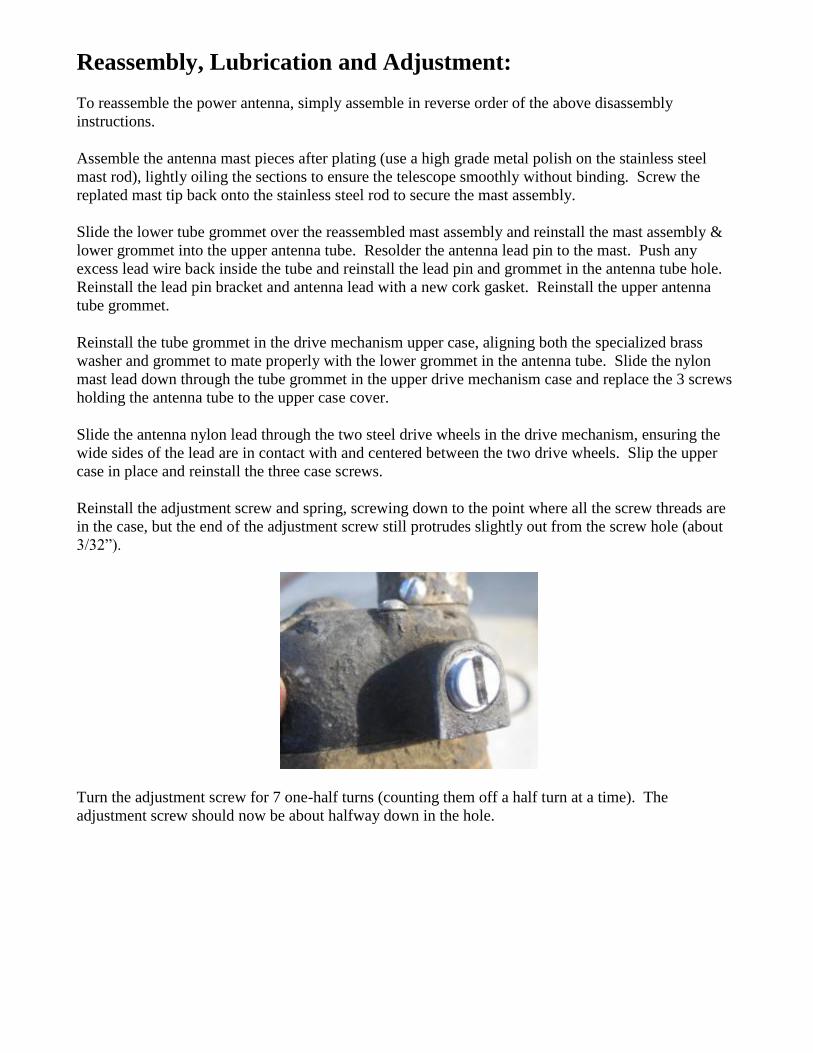
Reinstall the adjustment screw and spring, screwing down to the point where all the screw threads are
in the case, but the end of the adjustment screw still protrudes slightly out from the screw hole (about
3/32”).
Turn the adjustment screw for 7 one-half turns (counting them off a half turn at a time). The
adjustment screw should now be about halfway down in the hole.
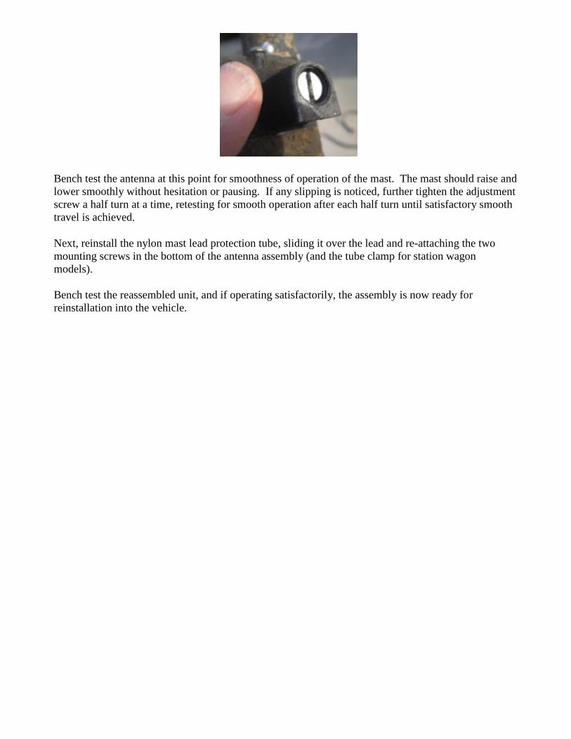
Bench test the antenna at this point for smoothness of operation of the mast. The mast should raise and
lower smoothly without hesitation or pausing. If any slipping is noticed, further tighten the adjustment
screw a half turn at a time, retesting for smooth operation after each half turn until satisfactory smooth
travel is achieved.
Next, reinstall the nylon mast lead protection tube, sliding it over the lead and re-attaching the two
mounting screws in the bottom of the antenna assembly (and the tube clamp for station wagon
models).
Bench test the reassembled unit, and if operating satisfactorily, the assembly is now ready for
reinstallation into the vehicle.