Service Manual - HOSHIZAKI · Service Manual Number: 73215 ... Peachtree City, GA 30269 Attn:...
55
Models KML-325MAJ, MWJ KML-500MAJ, MWJ KML-700MAJ, MWJ, MRJ Modular Crescent Cuber with Service Manual Number: 73215 Issued: 6-16-2017 hoshizakiamerica.com
Transcript of Service Manual - HOSHIZAKI · Service Manual Number: 73215 ... Peachtree City, GA 30269 Attn:...

ModelsKML-325MAJ, MWJKML-500MAJ, MWJKML-700MAJ, MWJ, MRJ
Modular Crescent Cuber with
Service Manual
Number: 73215Issued: 6-16-2017hoshizakiamerica.com

2
WARNINGOnly qualified service technicians should install and service the appliance. To obtain the name and phone number of your local Hoshizaki Certified Service Representative, visit www.hoshizaki.com. No installation or service should be undertaken until the technician has thoroughly read this Instruction Manual. Likewise, the owner/manager should not proceed to operate the appliance until the installer has instructed them on its proper operation. Failure to install, operate, and maintain the appliance in accordance with this manual will adversely affect safety, performance, component life, and warranty coverage and may result in costly water damage. Proper installation is the responsibility of the installer. Product failure or property damage due to improper installation is not covered under warranty.
Hoshizaki provides this manual primarily to assist qualified service technicians in the installation, maintenance, and service of the appliance.
Should the reader have any questions or concerns which have not been satisfactorily addressed, please call, send an e-mail message, or write to the Hoshizaki Technical Support Department for assistance.
Phone: 1-800-233-1940; (770) 487-2331Fax: 1-800-843-1056; (770) 487-3360
E-mail: [email protected]
618 Highway 74 SouthPeachtree City, GA 30269Attn: Hoshizaki Technical Support Department
NOTE: To expedite assistance, all correspondence/communication MUST include the following information:
• Model Number
• Serial Number
• Complete and detailed explanation of the problem.

3
CONTENTSImportant Safety Information ................................................................................................. 5I. Construction and Water/Refrigeration Circuit Diagram ....................................................... 7
A. Construction .................................................................................................................. 71. Air-Cooled (MAJ) ...................................................................................................... 72. Water-Cooled (MWJ) ............................................................................................... 83. Remote Air-Cooled (MRJ) ........................................................................................ 9
B. Water/Refrigeration Circuit Diagram ............................................................................ 101. Air-Cooled Models (MAJ) ....................................................................................... 102. Water-Cooled Models (MWJ) ..................................................................................113. Remote Models (MRJ) ........................................................................................... 12
II. Sequence of Operation and Service Diagnosis ............................................................... 13A. Sequence of Operation Flow Chart ............................................................................. 13
1. Operation Flow Chart ............................................................................................. 132. Shutdown Flow Chart ............................................................................................ 14
B. Service Diagnosis ....................................................................................................... 15C. Control Board Check ................................................................................................... 22D. Bin Control Check ....................................................................................................... 23E. Switches ...................................................................................................................... 24
1. Control Switch ........................................................................................................ 242. Service Switch ....................................................................................................... 24
F. Float Switch Check and Cleaning ................................................................................ 251. Float Switch Check ................................................................................................ 252. Float Switch Cleaning ............................................................................................ 26
G. Thermistor Check ........................................................................................................ 27H. Diagnostic Tables ........................................................................................................ 28
III. Controls and Adjustments ............................................................................................... 32A. Control Board Layout ................................................................................................. 33B. LED Lights and Audible Alarm Safeties ...................................................................... 34C. Settings and Adjustments ............................................................................................ 35
1. Default Dip Switch Settings .................................................................................... 352. Harvest Timer (S4 dip switch 1 & 2) ...................................................................... 353. Pump-Out Timer (S4 dip switch 3 & 4) .................................................................. 364. Pump-Out Frequency Control (S4 dip switch 5) ..................................................... 365. Harvest Pump Time (S4 dip switch 6) .................................................................... 376. Harvest Pump Timer Operation (S4 dip switch 7) .................................................. 377. Factory Use (S4 dip switch 8)................................................................................. 388. Freeze Timer (S4 dip switch 9 & 10) ...................................................................... 389. Float Switch Selector (S5 dip switch 1) ................................................................. 3810. Refill Counter (S5 dip switch 2 and 3) .................................................................. 38
11. Minimum Harvest Time (S5 dip switch 4) ............................................................... 3912. Anti-Slush (S5 dip switch 5) ................................................................................... 39
IMPORTANTThis manual should be read carefully before the appliance is serviced. Read the warnings and guidelines contained in this manual carefully as they provide essential information for the continued safe use, service, and maintenance of the appliance. Retain this manual for any further reference that may be necessary.

4
IV. Refrigeration Circuit and Component Service Information.............................................. 40A. Refrigeration Circuit Service Information .................................................................... 40B. Component Service Information .................................................................................. 43C. Water Regulating Valve Adjustment (water-cooled model) .......................................... 43
V. Maintenance .................................................................................................................... 44VI. Preparing the Appliance for Periods of Non-Use ............................................................ 45VII. Disposal ......................................................................................................................... 47VIII. Technical Information .................................................................................................... 48
A. Specification and Performance Data Sheets ............................................................... 481. KML-325MAJ .......................................................................................................... 482. KML-325MWJ ........................................................................................................ 493. KML-500MAJ ......................................................................................................... 504. KML-500MWJ ........................................................................................................ 515. KML-700MAJ ......................................................................................................... 526. KML-700MWJ ........................................................................................................ 537. KML-700MRJ.......................................................................................................... 54
B. Wiring Diagram .......................................................................................................... 55

5
Important Safety InformationThroughout this manual, notices appear to bring your attention to situations which could result in death, serious injury, damage to the appliance, or damage to property.
WARNING Indicates a hazardous situation which could result in death or serious injury.
NOTICE Indicates a situation which could result in damage to the appliance or property.
IMPORTANT Indicates important information about the use and care of the appliance.
WARNINGThe appliance should be destined only to the use for which it has been expressly conceived. Any other use should be considered improper and therefore dangerous. The manufacturer cannot be held responsible for injury or damage resulting from improper, incorrect, and unreasonable use. Failure to service and maintain the appliance in accordance with this manual will adversely affect safety, performance, component life, and warranty coverage and may result in costly water damage.To reduce the risk of death, electric shock, serious injury, or fire, follow basic precautions including the following:
• Only qualified service technicians should install and service this appliance.
• The appliance must be installed in accordance with applicable national, state, and local codes and regulations.
• Electrical connection must be hard-wired and must meet national, state, and local electrical code requirements. Failure to meet these code requirements could result in death, electric shock, serious injury, fire, or damage.
• The icemaker requires an independent power supply of proper capacity. See the nameplate for electrical specifications. Failure to use an independent power supply of proper capacity can result in a tripped breaker, blown fuses, damage to existing wiring, or component failure. This could lead to heat generation or fire.
• THE ICEMAKER MUST BE GROUNDED. Failure to properly ground the icemaker could result in death or serious injury.
• Move the control switch to the "OFF" position and turn off the power supply before servicing. Lockout/Tagout to prevent the power supply from being turned back on inadvertently.
• To reduce the risk of electric shock, do not touch the control switch or service switch with damp hands.
• Do not make any alterations to the unit. Alterations could result in electric shock, injury, fire, or damage to the unit.
• The appliance is not intended for use by persons (including children) with reduced physical, sensory, or mental capabilities, or lack of experience and knowledge, unless they have been given supervision or instruction concerning use of the appliance by a person responsible for their safety.

6
WARNING, continued• Children should be properly supervised around this appliance.
• Do not climb, stand, or hang on the appliance or allow children or animals to do so. Serious injury could occur or the appliance could be damaged.
• Do not use combustible spray or place volatile or flammable substances near the appliance. They might catch fire.
• Keep the area around the appliance clean. Dirt, dust, or insects in the appliance could cause harm to individuals or damage to the appliance.
Additional Warning for Remote Models
• THE REMOTE CONDENSER UNIT MUST BE GROUNDED. The power supply and ground connection to the remote condenser unit are supplied from the icemaker. Failure to properly ground the remote condenser unit could result in death or serious injury.
• Move the icemaker control switch to the "OFF" position and turn off the power supply to the icemaker before servicing the remote condenser unit. Lockout/Tagout to prevent the power supply from being turned back on inadvertently.
NOTICE• Follow the instructions in this manual carefully to reduce the risk of costly water
damage.
• In areas where water damage is a concern, install in a contained area with a floor drain.
• Install the appliance in a location that stays above freezing. Normal operating ambient temperature must be within 45°F to 100°F (7°C to 38°C).
• Do not leave the icemaker on during extended periods of non-use, extended absences, or in sub-freezing temperatures. To properly prepare the icemaker for these occasions, follow the instructions in "VI. Preparing the Appliance for Periods of Non-Use."
• Do not place objects on top of the appliance.
• The dispenser unit/ice storage bin is for ice use only. Do not store anything else in the dispenser unit/ice storage bin.

7
I. Construction and Water/Refrigeration Circuit Diagram
A. Construction
1. Air-Cooled (MAJ)
Thermostatic Bin Control
Water Supply Inlet
Condenser
Drier
Control Box
Spray Tubes
Control Switch
Pump Motor
Float Switch
Compressor
Thermostatic Expansion Valve
Fan Motor
Thermostatic Bin Control Bracket & Bulb Holder
Inlet Water Valve
Liquid Line Valve
High-Pressure Switch
Cleaning ValveDrain Valve
Model Shown: KML-500MAJ
Service Switch

8
2. Water-Cooled (MWJ)
Water Supply Inlet
Condenser
Drier
Control Box
Spray Tubes
Control Switch
Pump Motor
Float Switch
Compressor
Thermostatic Expansion Valve
Water Regulating Valve
Liquid Line Valve
Cleaning Valve
Thermostatic Bin Control
Thermostatic Bin Control Bracket & Bulb Holder
Inlet Water Valve
High-Pressure Switch
Model Shown: KML-325MWJ
Drain Valve
Service Switch

9
3. Remote Air-Cooled (MRJ)
Water Supply Inlet
Reciever
Drier
Control Box
Spray Tubes
Control Switch
Pump Motor
Float Switch
Compressor
Thermostatic Expansion Valve
Hot Gas Valve
Thermostatic Bin Control
Thermostatic Bin Control Bracket & Bulb Holder
Inlet Water Valve
Liquid Line Valve
High-Pressure Switch
Model Shown: KML-700MRJ
Crankcase Heater
Cleaning Valve
Drain Valve
Service Switch

10
B. Water/Refrigeration Circuit Diagram
1. Air-Cooled Models (MAJ)
Spray Tubes
Water Supply Inlet
Condenser
CondenserFan Motor
Drier
Hot Gas Valve
Compressor
Float Switch
Water Pump
Thermostatic Expansion Valve
Inlet Water Valve
Drain Valve
Cleaning Valve
Thermistor
Strainer
High-Pressure Switch
Heat Exchanger
Drain

11
2. Water-Cooled Models (MWJ)
Spray Tubes
Water Supply Inlet
Condenser
Drier
Hot Gas Valve
Compressor
Float Switch
Water Pump
Thermostatic Expansion Valve
Inlet Water Valve
Drain Valve
Thermistor
Strainer
High-Pressure Switch
Heat Exchanger
Water Regulating Valve
Drain
Cleaning Valve

12
3. Remote Models (MRJ)
Spray Tubes
Water Supply Inlet
Condenser
CondenserFan Motor
Drier
Hot Gas Valve
Compressor
Float Switch
Water Pump
Thermostatic Expansion Valve
Inlet Water Valve
Drain Valve
Thermistor
Strainer
High-Pressure Switch
Heat Exchanger
Headmaster
ReceiverLiquid Line Valve
Drain
Cleaning Valve

13
II. Sequence of Operation and Service Diagnosis
A. Sequence of Operation Flow Chart
1. Operation Flow Chart
Leg
end
: C
om
p–c
ompr
esso
rD
V–d
rain
val
veF
M–f
an m
otor
FM
R–f
an m
otor
-rem
ote
FS
–floa
t sw
itch
HG
V–h
ot g
as v
alve
LLV
–liq
uid
line
valv
eP
M–p
ump
mot
orW
V–i
nlet
wat
er v
alve
Co
mp
on
ents
En
erg
ized
wh
en t
he
Co
ntr
ol S
wit
ch is
in t
he
"SE
RV
ICE
" P
osi
tio
nW
hen
in th
e "S
ER
VIC
E"
posi
tion,
the
cont
rol s
witc
h su
pplie
s po
wer
to th
e se
rvic
e sw
itch
and
the
mac
hine
is in
ser
vice
mod
e.
The
ser
vice
sw
itch
has
thre
e po
sitio
ns: "
DR
AIN
," "
CIR
CU
LAT
E"
and
"WA
SH
." S
ee th
e in
form
atio
n be
low
for
deta
ils o
f eac
h fu
nctio
n.
DR
AIN
Pow
er is
sup
plie
d to
the
pum
p m
otor
and
dra
in v
alve
. Thi
s dr
ains
the
wat
er ta
nk.
CIR
CU
LAT
EP
ower
is s
uppl
ied
to th
e pu
mp
mot
or o
nly.
Thi
s ca
n be
use
d to
circ
ulat
e cl
eane
r ov
er th
e ou
tsid
e su
rfac
e of
the
evap
orat
or fo
r ex
tend
ed p
erio
ds o
f tim
e.
WA
SH
Pow
er is
sup
plie
d to
the
pum
p m
otor
and
byp
ass
valv
e. T
his
is u
sed
to c
ircul
ate
clea
ner
and
sani
tizer
ove
r bo
th th
e in
side
and
out
side
sur
face
s of
the
evap
orat
or.
1 to
3-m
in. h
arve
st ti
mer
in
cont
rol (
S4
dip
switc
h 1
& 2
)
• M
axim
um in
let w
ater
val
ve ti
me:
6 m
in. o
r th
e le
ngth
of
har
vest
min
us 5
0 se
c. (
S4
dip
switc
h 7)
, whi
chev
er is
sho
rter
.•
Max
imum
har
vest
tim
e: 2
0 m
in.
FS
che
ck
Op
erat
ion
Flo
w C
har
t
1. 1
-Min
ute
F
ill C
ycle
Cyc
le
Ste
ps
2. H
arve
st C
ycle
The
rmis
tor
in
cont
rol
3. F
reez
e C
ycle
• M
inim
um fr
eeze
tim
e: 5
min
.•
Max
imum
free
ze ti
me:
free
ze ti
mer
se
tting
(S
4 di
p sw
itch
9 &
10)
FS
in c
ontr
ol
4. P
um
p-O
ut
Cyc
le•
Fact
ory
set f
or e
very
10
th c
ycle
(S4
dip
switc
h 3
& 4
)
WV
ene
rgiz
ed
FS
ope
n
Co
mp
ene
rgiz
edH
GV
ene
rgiz
edW
V e
nerg
ized
The
rmis
tor
tem
pera
ture
rea
ches
48
°F (
9°C
) (3
.9 k
Ω o
r le
ss).
Har
vest
tim
er s
tart
s (1
to 3
min
.). F
S o
pen
Co
mp
con
tinue
sF
M e
nerg
ized
FM
R e
nerg
ized
LLV
ene
rgiz
edP
M e
nerg
ized
H
GV
de-
ener
gize
d
FS
clo
sed
Co
mp
con
tinue
sD
V e
nerg
ized
HG
V e
nerg
ized
PM
sto
ps fo
r 2
sec.
, the
n
en
ergi
zed
for
10/2
0 se
c.F
M d
e-en
ergi
zed
FM
R d
e-en
ergi
zed
LLV
de-
ener
gize
d
FS
che
ckS
tart
up
If F
S is
ope
n, C
omp
stop
s an
d cy
cle
retu
rns
to 1
-min
. fill.
5-m
in. m
inim
um
free
ze ti
mer
in
cont
rol
FS
clo
sed
FS
ope
ns o
r fr
eeze
tim
er
term
inat
es
Har
vest
Pu
mp
T
imer 50
sec
.
PM
ene
rgiz
edW
V d
e-en
ergi
zed
An
ti-S
lush
The
rmis
tor
tem
pera
ture
reac
hes
36°F
(2.
2°C
)(5
.8 k
Ω).
PM
de-
ener
gize
d fo
r
10
sec
.

14
1. B
in F
ull
With
in 1
0 se
c. a
fter
ice
cont
acts
T
BC
bul
b, ic
emak
er
shu
ts d
own.
Sh
utd
ow
n
and
Res
tart
TB
C O
pera
tion
Ice
cont
acts
TB
C b
ulb
2. Ic
emak
er O
ff
All
com
pone
nts
de
-ene
rgiz
ed.
3. Ic
e L
evel
Lo
wer
ed N
o ic
e to
uchi
ng T
BC
bul
b.
Ice
mak
er s
tart
s at
"
1. 1
-Min
ute
Fill
Cyc
le."
TB
C c
lose
dT
BC
ope
nA
ll co
mpo
nent
s de
-ene
rgiz
ed
To 1
. 1-M
inu
te F
ill C
ycle
Sh
utd
ow
n F
low
Ch
art
NO
TE
: con
trol
boa
rd g
reen
"B
C C
LOS
ED
" LE
D o
n co
ntin
uous
ly w
hen
the
K4
jum
per
is in
pla
ce.
2. Shutdown Flow Chart

15
B. Service Diagnosis
WARNING• The appliance should be diagnosed and repaired only by qualified service
personnel to reduce the risk of death, electric shock, serious injury, or fire.
• Risk of electric shock. Control switch in "OFF" position does not de-energize all loads Use extreme caution and exercise safe electrical practices.
• Moving parts (e.g., fan blade) can crush and cut. Keep hands clear.
• Before servicing the appliance, move the control switch to the "OFF" position and turn off the power supply.
• CHOKING HAZARD: Ensure all components, fasteners, and thumbscrews are securely in place after the appliance is serviced. Make sure that none have fallen into the dispenser unit/ice storage bin.
• Make sure all food zones in the appliance and dispenser unit/ice storage bin are clean after service.
The diagnostic procedure is a sequence check that allows you to diagnose the electrical system and components. Before proceeding, check for correct installation, proper voltage per nameplate, and adequate water supply. Check CB using the steps in "II.C. Control Board Check." Check dip switch settings to assure that S4 dip switch 3, 4, 7, 8, 9, 10 and S5 dip switch 1 through 5 are in the factory default position. S4 dip switch 1, 2, 5, 6 are cleaning adjustments and the settings are flexible. For factory default settings, see "III.C.1. Default Dip Switch Settings."
Note: • When checking high voltage (115VAC), always choose a white (W) neutral wire to establish a good neutral connection.
• When checking voltage from the CB K1 connector (10 pin connector), pull CB K1 connector out slightly to allow room for multimeter test leads contact.
Confirm that the location meets installation requirements:
• The appliance is not intended for outdoor use. Normal operating ambient temperature should be within 45°F to 100°F (7°C to 38°C).
• Allow 6" (15 cm) clearance at rear, sides, and top for proper air circulation and ease of maintenance and/or service should they be required.
• The appliance should not be located in a corrosive environment.
1) Turn off the power supply, then access the control box. Move the control switch to the "OFF" position. Clear any ice from BC.
2) Check that the 115VAC 10A fuse is good.

16
1. Diagnosis
3) Power On: Turn on the power supply, then move the control switch to the "ICE" position. A 5-sec. delay occurs. CB red "POWER OK" LED and green "BC CLOSED" LED turn on. If yellow "BC OPEN" LED is on (indicating a missing or loose jumper (4A4883G01)), check that the jumper is securely in place. Move ice away from TBC bulb. If yellow "BC OPEN" LED stays on, see "II.D. Bin Control Check." Note: • CB red "POWER OK" LED remains on unless the 10.5VAC power supply is
interrupted (K2 connector).
• Check CB using the steps in "II.C. Control Board Check."
• Confirm CB green "BC CLOSED" LED is on. If CB yellow "BC OPEN" LED is on, confirm jumper (4A5883G01) is in place on CB K4 red connector.
a) Power On Diagnosis: If CB red "POWER OK" LED is off, confirm 10A fuse is good. Check for 115VAC at control switch #2 (BK) to neutral (W) then at control switch #3 (P) to neutral (W). If 115VAC is present on #2 (BK) and not on #3 (P), replace control switch. If 115VAC is present on control switch #3 (P), check for 115VAC at HPS (P) wire to neutral (W) then HPS (BK) wire to neutral (W). If 115VAC is present at HPS (P) wire and not at HPS (BK) wire, HPS is open. See HPS Diagnosis below. If 115VAC is present at HPS (BK) wire, check for 10.5VAC at CB K2 #1 red (R) wire to CB K2 #2 red (R) wire. If 10.5VAC is not present, check CT continuity. If open, replace CT.
b) HPS Diagnosis: Let refrigeration circuit pressures equalize. If HPS does not reset and pressures are equalized, replace HPS. Check that the condenser coil is not clogged or restricted. If pressures are not equalized, reclaim refrigerant and diagnose refrigeration circuit restriction. Check that there are no restrictions in the refrigeration circuit. Harvest Cycle: HGV, strainer, or check valve. Freeze Cycle: FM, FMR, TXV, WRV, HM, LLV, strainer, check valve, drier, and damaged line set or fitting.
4) 1-Min. Fill Cycle – LED 4 is on. WV and X11 relay energize. Water begins to fill the water tank. After 1 min., CB checks for a closed FS. If FS is closed, the harvest cycle begins (X10, X12, X14, Comp, HGV, and FMR energize), Continue to step 5a. If FS is open, WV remains energized through additional 1-min. fill cycles until water enters the water tank and FS closes (low water safety protection during initial start up and at the end of each harvest). Diagnosis: Check that water enters the water tank. If not, check that the water supply line shut-off valve is open and screens or external filters are clear. Check for 115VAC at CB K1 #6 (O) to neutral (W). If 115VAC is not present, replace CB. If 115VAC is present, and WV does not energize, check for 115VAC at WV. If 115VAC is present, check coil continuity. If open, replace WV. If the water tank fills, but the appliance fails to start harvest (Comp energized), check for open FS. See "II.E. Float Switch Check and Cleaning." If FS is closed and CB fails to start the harvest cycle after 1 min., replace CB.

17
5a) Initial Harvest Cycle – LEDs 1, 4, and 2 are on. WV and X11 relay continue. Comp, HGV, X10, X12, and X14 relays energize. CB monitors the warming of the evaporator via the thermistor located on the suction line. When the thermistor reaches 48°F (9°C), CB reads 3.9 kΩ from the thermistor and turns harvest termination over to the harvest timer (S4 dip switch 1 & 2). The harvest timer has settings of 60, 90, 120, and 180 sec. The pump-out timer (S4 dip switch 3 & 4) acts in place of the harvest timer during cycles with a pump-out (S4 dip switch 5). WV and X11 relay are energized during harvest for a maximum of 6 min. or the length of harvest minus 50 sec., whichever is shorter. 50 sec. before harvest terminates, PM energizes. See step 5b below.
a) Comp Diagnosis: Check that evaporator is warming. If not, confirm that Comp energizes. If not, check for 115VAC at CB K1 #1 or #9 (V) to neutral (W). If 115VAC is not present, check for 115VAC at CB K1 #7 or #10 (BK) to neutral (W). If 115VAC is present at #7 or #10 (BK) and not at #1 or #9 (V), replace CB. If 115VAC is present, check for 115VAC at CR solenoid. If 115VAC is present, confirm contacts are closed. If not, replace CR. If CR contacts are closed, check Comp start and run capacitors, Comp start relay, and Comp motor winding.
b) HGV Diagnosis: If Comp is energized and evaporator is not warming, check that HGV energizes and opens. Check for 115VAC at CB K1 #2 (P) to neutral (W). If 115VAC is not present, replace CB. If 115VAC is present, check for 115VAC at HGV coil and check HGV coil continuity. Replace as needed.
c) LLV Diagnosis: Confirm that LLV is de-energized and closed (not bypassing). If energized, replace CB. If de-energized and bypassing, replace LLV.
d) WRV Diagnosis: Confirm WRV is not leaking by.
e) CCH Diagnosis (remote model): Confirm X14 relay energizes, de-energizing the CCH.
5b) Harvest Pump Time – LEDs 1, 3, and 2 are on. When the thermistor reaches 48°F (9°C), CB reads 3.9 kΩ from the thermistor and turns harvest termination over to the harvest timer (S4 dip switch 1 & 2). 50 sec. before the harvest timer terminates, LED 3 turns on and PM energizes. Comp, HGV, X10, X12, and X14 relays continue. LED 4 turns off, WV and X11 relay de-energize.
a) Thermistor Diagnosis: Place a thermometer on the suction line next to the thermistor. Has it warmed to 48°F (9°C) or warmer? Confirm thermistor status. See "II.F. Thermistor Check."
b) Control Board Diagnosis: If the thermistor reading is in proper range, dip switch 7 is on, and WV continues, check for 115VAC at CB K1 #6 (O) to neutral (W). If 115VAC is present, and LED 4 is off, replace CB. If LED 3 is on and PM is not energized, check for 115VAC at CB K1 #5 (DBU) to neutral (W). If 115VAC is not present, replace CB.
c) Relay Diagnosis: If 115VAC is present and PM is not energized, check for 115VAC at X10 relay #8 (Y) to neutral (W). If 115VAC is not present on X10 relay #8 (Y), check for 115VAC at X10 relay #4 (P) and X10 relay #6 (Y) to neutral (W) (latching circuit). If 115VAC is present at X10 relay #4 (P) and not at X10 relay #6 (Y), replace X10 relay. If 115VAC is present on X10 relay #8 (Y) and PM is not energized, check for 115VAC at X10 relay #3 (R) and X10 relay #5 (DBU) to neutral (W). If 115VAC is present at X10 relay #5 (DBU) and not at X10 relay #3 (R), replace X10 relay.

18
d) Control Switch Diagnosis: If 115VAC is present at X10 relay #3 (R), check for 115VAC at control switch #6 red (R) wire to neutral (W). Next, check for 115VAC at control switch #5 (Y) to neutral (W). If 115VAC is present at control switch #6 red (R) wire and not at control switch #5 (Y), check control switch continuity. If contacts are open, replace control switch.
e) Pump Motor Diagnosis: If 115VAC is present at control switch #5 (Y), check PM capacitor and motor winding continuity.
5c) Initial Harvest Cycle Termination Diagnosis: When the harvest timer (S4 dip switch 1 & 2) terminates, harvest cycle terminates. If 1-min. fill cycle starts after harvest timer terminates, check that FS is clean and operating properly, see "II.E. Float Switch Check and Cleaning." If FS is closed, CB proceeds to the next cycle. If not, replace CB.Note: The minimum total time allowed by CB for a complete harvest cycle is 2 min.
Maximum harvest time allowed is 20 min.
IMPORTANT! S4 dip switch 7 must remain on. Otherwise, PM will not energize during the last 50 sec. of harvest.
6) Freeze Cycle – LED 1 is on. Comp, PM, and X14 relay continue. FMR, FM, and LLV energize. HGV, X10, and X12 relays de-energize. Appliance is held in freeze by a 5-min. short cycle protection timer. After 5-min. timer terminates and FS opens, freeze cycle terminates. When the thermistor reaches 36°F (2.2°C), CB reads 5.8 kΩ from the thermistor and de-energizes the PM for 10 sec. (anti-slush). After 10 sec. CB energizes PM and freeze cycle continues. Note: PM power supply switches from CB K1 #5 (DBU) in harvest to K1 #4 (R) in freeze.
a) Freeze Cycle Diagnosis: Confirm Comp, PM, and X14 relay continue. Confirm that FMR, FM, and LLV energize. Confirm WRV opens. Next, confirm HGV, X10, and X12 relays de-energize. During the first 5 min. of freeze, confirm evaporator is cooling. If not, confirm WV de-energized (not leaking by), HGV de-energized (not bypassing), FM, FMR, and LLV energize, TXV and HM operate correctly, WRV opens, Comp is efficient, and refrigerant charge is correct. See "VIII.A. Specification and Performance Data Sheets." When the thermistor reaches 36°F (2.2°C), CB reads 5.8 kΩ from the thermistor and de-energizes the PM for 10 sec. then, energizes PM for the duration of the freeze cycle.
b) Comp Diagnosis: If Comp de-energizes once freeze begins, check that appliance has not shut off on HPS ("POWER OK" LED off). If so, check "3)b) HPS Diagnosis." If "POWER OK" LED is on, check for 115VAC at CB K1 #1 (V) or #9 (V) to neutral (W). If 115VAC is not present and LED 1 is on, replace CB. If 115VAC is present, check for 115VAC at CR coil. If 115VAC is present, check CR coil and contact continuity. Replace as needed. If CR is okay, check Comp start relay and start and run capacitors. Next, check Comp motor winding continuity. If Comp is energized but evaporator is not cooling, check for an inefficient Comp. See "VIII.A. Specification and Performance Data Sheets."

19
c) WV and HGV Diagnosis: If WV is energized, check for 115VAC at CB K1 #6 (O) to neutral (W). If 115VAC is present after PM energizes in harvest cycle, replace CB. If 115VAC is not present, replace WV (bypassing). If HGV did not de-energize at the end of harvest, check for 115VAC at CB K1 #2 (P) to neutral (W). If 115VAC is present 50 sec. after PM energizes, replace CB. If 115VAC is not present, replace HGV (bypassing).
d) PM Diagnosis: Confirm water is flowing over evaporator from PM and not WV. If PM de-energizes once freeze begins or fails to energize after 10 sec. anti-slush, check for 115VAC at CB K1 #4 (R) to neutral (W). If 115VAC is not present, replace CB. If 115VAC is present and PM is de-energized, check for 115VAC at control switch #6 (R) to neutral (W) and control switch #5 (Y) to neutral (W). If 115VAC is present at control switch #6 (R) and not at control switch #5 (Y), check control switch continuity. Replace as needed. If 115VAC is present at control switch #5 (Y) to neutral (W), check PM capacitor and motor winding continuity.
e) FM, FMR, and LLV Diagnosis: If FM, FMR, or LLV does not energize, check for 115VAC at CB K1 #3 (BK) to neutral (W). If 115VAC is not present, replace CB. If 115VAC is present: For FM, check capacitor, motor winding, and blade for binding. For FMR, check for 115VAC at the FMR junction box. If 115VAC is not present, check icemaker wiring connections. If 115VAC is present, check for voltage at condenser unit. If 115VAC is not present, check field wiring connections. If 115VAC is present, check FMR capacitor, motor winding, and fan blade for binding. For LLV, check coil voltage and continuity.
f) Refrigerant Pressures, HM, and TXV Diagnosis: If evaporator is still not cooling, check refrigerant pressures. See "VIII.A. Specification and Performance Data Sheets." Next, check HM operation. If refrigeration pressures are above HM setpoint and HM is bypassing, replace HM. Check TXV for proper operation. Remove TXV bulb and hold it in your hand, refrigerant low-side pressure should rise, place TXV bulb in ice water, refrigerant low-side pressure should drop. A 10 to 15 pound pressure swing between warm and cold conditions indicate a good TXV. If a 10 to 15 pound swing is not present, replace TXV.
g) WRV Diagnosis: WRV is factory set and generally no adjustment is required. If WRV fails to open in freeze, check for proper refrigerant pressures. See "VIII.A. Specification and Performance Data Sheets." If refrigerant pressures are correct and WRV does not open, adjust or replace as needed. See "IV.C. Water Regulating Valve Adjustment (water-cooled models)."
h) Freeze Termination Diagnosis: After 5 min. in freeze, disconnect CB K5 FS connector. 15 sec. later appliance should switch out of the freeze cycle (15 second delay after FS opens before terminating the freeze cycle). If appliance remains in freeze longer than 15 sec. after FS removed, replace CB. If appliance switches with FS removed but would previously not switch out of freeze with FS connected (long freeze - 3 beep alarm), see "II.E. Float Switch Check and Cleaning."
Note: Normal freeze cycle will last 20 to 40 min. depending on model and conditions. Cycle times and pressures should follow performance data provided in this manual. See "VIII.A. Specification and Performance Data Sheets."

20
i) Short Freeze Cycle Diagnosis: Confirm water tank fills and overflows during 1 min. fill and harvest cycles. If not, check water supply filters, shut-off valve, WV screen. If water tank empties before 5 min. timer terminates and freeze cycle is short, check that DV is not leaking by or energized (water flowing through DV). If DV is leaking by, remove and clean DV, replace as needed. If water tank is full, see "II.E. Float Switch Check and Cleaning." for erratic operating FS.
7) Pump-Out Cycle – LEDs 1, 3, and 2 are on (10/20 second pump-out). Timing of the first pump-out is determined by S4 dip switch 5. See the table below.
Control Board Settings
S4 Dip Switch Setting Pump-Out Frequency
1st Pump-OutNo. 5
OFF Every 10 cycles After 11th freeze cycle
ON Every cycle After 2nd freeze cycle
Comp and X14 relay continue, HGV energizes, FM, FMR, and LLV de-energize. NOTICE! S4 dip switch 3 & 4 must not be set to 3 off and 4 on. Otherwise, LED 4 turns on energizing WV and X11 relay. Once X10 relay energizes, the DV cannot energize. PM stops for 2 sec., then PM and DV energize for 10/20 sec. depending on pump-out timer (S4 dip switch 3 & 4) setting. When the pump-out timer terminates, pump-out is complete. The pump-out frequency control (S4 dip switch 5) is factory set, and generally no adjustment is required. However, the pump-out frequency control can be set to have a pump-out occur every cycle, or every 10 cycles. For details, see "III.C.4. Pump-Out Frequency Control (S4 dip switch 5)."
a) Pump-Out Diagnosis: In the freeze cycle before pump-out (see table above), after 5 min. of freeze disconnect CB black K5 connector (FS connector). Check that CB LEDs 1, 3, and 2 are on, PM stops, then re-starts, DV energizes, and water is flowing down the drain through DV.
b) CB Diagnosis: Confirm FMR, FM, and LLV de-energize. If FRM, FM, or LLV are energized with LEDs 1, 3, and 2 on, replace CB. If PM does not stop and re-start and DV does not energize, check that CB LEDs 1, 3, and 2 are on. If not, replace CB. If LEDs 1, 3, and 2 are on and PM and DV do not energize, check for 115VAC at CB K1 #5 (DBU) to neutral (W). If 115VAC is not present, replace CB.
c) X10 and X11 Relays: If 115VAC is present at CB K1 #5 (DBU), check for 115VAC at X10 relay #1 (DBU) to neutral (W). If 115VAC is not present, check that X10 relay is de-energized. If X10 relay is de-energized and 115VAC not present at X10 relay #1 (DBU), replace X10 relay (contacts sticking). If X10 relay is energized, check X11 relay status. If X11 relay is energized, check that S4 dip switch 3 and 4 are not set to 3 on and 4 off positions, if not and X11 is energized, replace CB. If X11 relay is de-energized and X10 relay is energized, replace X11 relay (contacts sticking).
d) X12 Relay: If 115VAC is present at X10 #1 (DBU), check for 115VAC at X12 relay #5 (DBU) to neutral (W) and X12 relay #3 (DBU) to neutral (W). If 115VAC is present at X12 relay #5 (DBU) and not at X12 relay #3 (DBU), check for 115VAC at X12 relay #8 (P) to neutral (W). If 115VAC is present at X12 relay #8 (P) and X12 relay is de-energized, replace X12 relay. If 115VAC is not present, check CB K1 #2 (P) to neutral (W). If 115VAC is not present (HGV de-energized as well), replace CB.

21
e) X13 Relay - If 115VAC is present at X12 terminal #3 (DBU) to neutral and PM and DV are not energized, check for 115VAC at X13 terminal #8 (DBU) to neutral (W). If 115VAC is present and X13 relay is de-energized, replace X13 relay. (1) For PM and X13 Relay: If 115VAC is present at X13 terminal #8 (DBU), check
for 115VAC at X13 relay #6 (BK) and X13 relay #4 (Y) to neutral (W). If 115VAC is present at X13 relay #6 (BK) and not at X13 relay #4 (Y), replace X13 relay (contacts sticking open). If 115VAC is present at X13 relay #4 (Y) and PM is not energized, check PM capacitor, motor winding, and impeller for binding.
(2) For DV and X13 Relay: If 115VAC is present at X13 terminal #8 (DBU), check for 115VAC at X13 relay #5 (DBU) and X13 relay #3 (W/BU) to neutral (W). If 115VAC is present at X13 relay #5 (DBU) and not at X13 relay #3 (W/BU), replace X13 relay (contacts sticking open). If 115VAC is present at X13 relay #3 (W/BU) and DV is de-energized, check DV coil continuity, make sure the drain line is not clogged and that DV is clean and operating properly.
8) Normal Harvest Cycle – Same as the initial harvest cycle. Return to step 5a) above. Note: Appliance continues to cycle until TBC is satisfied or power is switched off. The
appliance always restarts at the 1-min. fill cycle.
9) Shutdown
a) Thermostatic Bin Control (TBC): When the appliance is running, hold ice in contact with the thermostatic bulb. BC switch opens within 10 sec., shutting down the appliance. TBC is factory set, and generally no adjustment is required. However, adjustment may be needed in some conditions, particularly at higher altitude locations. Diagnosis: See "II.D. Bin Control Check." CB red K4 connector must have the jumper in place. When the jumper is in place, the green "BC CLOSED" LED remains on. If the jumper is not in place, yellow "BC OPEN" LED turns on and the icemaker turns off and remains off until the jumper is replaced in its original position. NOTICE! CB red K4 connector jumper (4A4883G01) must be in place.
Legend: CB–control board; Comp–compressor; CR–compressor relay; DV–drain valve; FM–fan motor; FMR–fan motor-remote; FS–float switch; HGV–hot gas valve; HM–headmaster (C.P.R.); HPS–high-pressure switch; LLV–liquid line valve; PM–pump motor; TBC; thermostatic bin control; TXV–thermostatic expansion valve; WRV–water regulating Valve; WV–inlet water valve

22
C. Control Board CheckBefore replacing CB that does not show a visible defect and that you suspect is bad, always conduct the following check procedure. This procedure will help you verify your diagnosis.
Alarm Reset: If CB is in alarm (beeping), press the "ALARM RESET" button on CB while CB is beeping. WARNING! Risk of electric shock. Care should be taken not to touch live terminals. Once reset, the icemaker starts at the 1-minute fill cycle. For audible alarm information, see "III.B. LED Lights and Audible Alarm Safeties."
1) Check the dip switch settings to assure that S4 dip switch 3, 4, 7, 8, 9, 10 and S5 dip switch 1 through 5 are in the factory default position. S4 dip switch 1, 2, 5, 6 are cleaning adjustments and the settings are flexible. For factory default settings, see "III.C.1. Default Dip Switch Settings."
2) Move the control switch to the "ICE" position. If the red "POWER OK" LED is on, control voltage is good, continue to step 3. If the "POWER OK" LED is off, check CT secondary circuit. CT output is 10.5VAC at 115VAC primary input. If the secondary circuit has proper voltage and the red LED is off, replace CB.
If the secondary circuit does not have proper voltage (10.5VAC), check CT primary circuit. Check for 115VAC at control switch #2 (BK) wire and control switch #3 (P) wire to neutral (W). If 115VAC is present at control switch #2 (BK) wire and not at control switch #3 (P) wire, replace control switch. If 115VAC is present at control switch #3 (P) wire, check for 115VAC at HPS (BK) wire to neutral (W). If 115VAC is not present, see "B.1. or 2. 3)b) HPS Diagnosis." If 115VAC is present check CT coil continuity. Replace as needed. For additional checks, see "II.G.1. No Ice Production."
3) The "OUTPUT TEST" button provides a relay sequence test. Make sure the control switch is in the "ICE" position, then press the "OUTPUT TEST" button. For the correct lighting sequence, see the table below. Note that the order of the LEDs from the outer edge of the control board is 1, 4, 3, 2. Components (e.g., compressor) cycle during the test.
Control Board Correct LED Lighting Sequence
"J" 1, 4, 3, 2
Following the test, the icemaker begins operation at the 1-minute fill cycle. If the LEDs do not light as described above, replace CB.
4) To verify voltage output from CB to the components, slide the CB K1 connector out far enough to allow multimeter lead contact. With the icemaker in the cycle to be tested, check output voltage from the corresponding pin on CB K1 connector to a neutral (W) wire. If output voltage is not found and the appropriate LED is on, replace CB.
Legend: CB–control board; CT–control transformer

23
D. Bin Control Check
1. Thermostatic Bin Control Check TBC shuts down the icemaker within 10 sec. when ice contacts the thermostatic bulb, regardless of the cycle at activation.
NOTICEWhen the ambient temperature is below 45°F (7°C), TBC opens and shuts down the appliance even if the ice storage bin is empty. When BC is set in the prohibited range, the appliance operates continuously even if the ice storage bin is filled with ice. Setting in the prohibited range may result in severe damage to the appliance.
TBC is factory set, and generally no adjustment is required. However, adjustment may beneeded in some conditions, particularly at higher altitude locations.
Note: On thermostatic bin control models, a jumper (4A4883G01) must be placed on CB red K4 connector. Otherwise, CB yellow "BC OPEN" LED is on and appliance will not start.
To check TBC, follow the steps below.
1) Turn off the power supply.
2) Remove the front panel, then move the control switch to the "OFF" position.
3) Remove the control box cover, then clear any ice away from TBC bulb.
4) Disconnect TBC wires from TBC switch.
5) Hold your hand around the bulb to warm it up.
6) Check for continuity across TBC switch. If closed, continue to step 6. If open, adjust or replace TBC.
7) With the multimeter test leads still in place, hold ice on TBC bulb to lower the temperature. Within 10 sec., TBC switch should open. If it remains closed, adjust or replace TBC.
Legend: TBC–thermostatic bin control

24
E. SwitchesTwo control switches are used to control operation. These switches are referred to as the "control switch" and the "service switch" and are located on the control box.
1. Control SwitchThe control switch has three positions: "OFF" for power off, "ICE" for icemaking, and "SERVICE" to activate the service switch.
2. Service SwitchWhen the control switch is in the "SERVICE" position, the control switch supplies power to the service switch and the machine is in service mode. The service switch has three positions: "DRAIN, "CIRCULATE," and "WASH." See the information below for details of each function.
Note:1. When the service switch is activated, power is supplied to the water pump in all
three positions.2. When the control switch is in the "OFF" position or in the "ICE" position, the
service switch has no power and can be left in any position.
a) DRAINThis model utilizes a pump-out drain system. When the service switch is active and placed in the "DRAIN" position, power is supplied to the pump, service relay, and drain valve.
b) CIRCULATEWhen the service switch is active and placed in the "CIRCULATE" position, power is supplied to the pump only. This operation can be used to circulate cleaner for extended periods of time over the outside surface of the evaporator.
c) WASHThis model utilizes a solenoid operated wash (bypass) valve. When the service switch is active and placed in the "WASH" position, power is supplied to the pump and the wash valve. This operation is used to circulate cleaner and sanitizer over both the inside and outside of the evaporator.

25
F. Float Switch Check and CleaningFS is used to determine that there is sufficient water in the water tank after the 1-min. fill cycle and after each harvest cycle. FS is also used to determine that the appropriate volume of water has been converted into ice before switching out of the freeze cycle. No adjustment is required.
1. Float Switch CheckTo check FS, follow the steps below.
1) Remove the front panel, then move the control switch to the "SERVICE" position. Move the service switch to the "DRAIN" position.
2) Allow the water to drain from the water tank, then move the control switch to the "OFF" position. Turn off the power supply.
3) Remove the control box cover.
4) Disconnect FS connector from CB K5 (black) connector.
5) Check for continuity across FS leads. With the water tank empty, FS should be open. If open, continue to step 6. If closed, follow the steps in "II.E.2. Float Switch Cleaning." After cleaning FS, check it again. Replace if necessary.
6) Reconnect FS connector to CB K5 (black) connector, then replace the control box cover in its correct position.
7) Move the control switch to the "ICE" position. Replace the front panel in its correct position, then turn on the power supply. After 1 min., the 1-min. fill cycle should end and the initial harvest cycle should begin. If the initial harvest cycle begins, FS is good and the check is complete. If the initial harvest cycle does not begin, continue to step 8.
8) Turn off the power supply.
9) Remove the front panel. Move the control switch to the "OFF" position.
10) Remove the control box cover.
11) Disconnect FS connector from CB K5 (black) connector.
12) Check for continuity across FS leads. With the water tank full, FS should be closed. If FS is closed and the icemaker will not switch from the 1-min. fill cycle to the initial harvest cycle, replace CB.
If FS is open, confirm that the water tank is full. If the water tank is not full, check the water supply, water filters, and inlet water valve. If the water tank is full, follow the steps in "II.E.2. Float Switch Cleaning." After cleaning FS, check it again. Replace if needed.
Legend: CB–control board; FS–float switch

26
2. Float Switch CleaningDepending on local water conditions, scale may build up on FS. Scale on the switch can cause the float to stick. In this case, FS should be cleaned.
1) Remove the front panel, then move the control switch to the "SERVICE" position. Move the service switch to the "DRAIN" position.
2) Allow the water to drain from the water tank, then move the control switch to the "OFF" position. Turn off the power supply.
6) Remove the FS from the PM bracket and water tank.
7) Remove the retainer rod from the bottom of FS housing, then remove the float. Be careful not to bend the retainer rod excessively when removing it. See Fig. 1.
6) Wipe down FS housing, shaft, float, and retainer rod with a mixture of 1 part Hoshizaki "Scale Away" and 25 parts warm water. Rinse the parts thoroughly with clean water.
7) Reassemble FS assembly and replace it in its correct position.
8) Move the control switch to the "ICE" position.
9) Replace the front panel in its correct position.
10) Turn on the power supply to start the automatic icemaking process.
Legend: CB–control board; FS–float switch; PM–pump motor
Float
Float Switch Housing
Retainer Rod
Flush
Vent
Shaft
Fig. 4

27
G. Thermistor CheckTo check thermistor resistance, follow the steps below.
1) Turn off the power supply.
2) Remove the front panel. Move the control switch to the "OFF" position.
3) Remove the control box cover.
4) Remove the thermistor from the refrigerant tubing.
5) Immerse the thermistor sensor portion in a glass containing ice and water for 2 or 3 min.
6) Disconnect the thermistor connector from CB K3 connector and check the resistance between thermistor leads. Normal range is 4.7 to 6.2 kΩ. If outside the normal range, replace the thermistor. See "IV.B. Component Service Information." If within the normal range, continue to the next step.
7) Replace the thermistor in its correct position. See "IV.B. Component Service Information."
8) Reconnect the thermistor connector to CB K3 connector.
9) Replace the control box cover in its correct position.
10) Move the control switch to the "ICE" position.
11) Replace the front panel in its correct position.
12) Turn on the power supply.
13) Once the harvest cycle starts (Comp energizes), begin timing the harvest cycle.
14) The harvest timer and harvest cycle should terminate within 2 to 5 min. If the harvest cycle does not terminate within 2 to 5 min., replace CB.
Legend: CB–control board; Comp–compressor

28
H. Diagnostic Tables
1. No Ice Production
No Ice Production - Possible Cause
1. Power Supply a) Off, blown fuse, or tripped breaker.
b) Not within specifications.
2. Thermostatic Bin Control See "II.D. Bin Control Check"
a) Engaged with bin filled with ice.
b) Ambient temperature too cool.
c) Set too warm.
d) Bulb out of position.
e) Open contacts, defective.
3. Fuse (Control Box) a) Blown.
4. Control Switch a) In "OFF" or "SERVICE" position.
b) Bad contacts.
5. High-Pressure Switch a) Dirty condenser.
b) Fan motor not operating.
c) Refrigerant overcharged.
d) Bad contacts.
e) Refrigerant lines or components plugged.
6. Control Transformer (115VAC/10.5VAC)
a) Coil winding open or shorted.
7. Control BoardSee "II.C. Control Board Check"
a) In alarm.
b) Yellow "BC OPEN" LED on: Jumper loose or missing on models with TBC.
c) Defective.
8. Water Supply a) Water supply off or improper water pressure.
b) External water filters clogged.
9. Inlet Water Valve a) Screen or orifice clogged.
b) Coil winding open.
c) Water valve open in freeze cycle.
10. Float SwitchSee "II.E. Float Switch Check and Cleaning"
a) Float does not move freely.
b) Defective.
11. Compressor a) Compressor relay contacts bad or coil winding open.
b) Start capacitor or run capacitor defective.
c) Internal protector open.
d) Start relay contacts bad or coil winding open (single phase).
e) Compressor defective.
12. Hot Gas Valve a) Closed in harvest cycle.
b) Open in freeze cycle.
13. ThermistorSee "II.F. Thermistor Check"
a) Loose, disconnected, or defective.
14. Pump Motor a) Motor winding open.
b) Bearing worn out or locked rotor.
c) Defective capacitor.
15. Thermostatic Expansion Valve a) Bulb loose.
b) Operating erratically.

29
No Ice Production - Possible Cause
16. Liquid Line Valve a) Closed in freeze cycle.
b) Open in harvest cycle.
17. Fan Motor/Fan Motor-Remote (off on HPS)
a) Motor winding open.
b) Bearing worn out or locked rotor.
c) Defective capacitor.
18. Water System a) Water leaks causing short freeze time.
2. Freeze-UpDefrost and clean the icemaker prior to diagnosing freeze-up. Fill out a freeze-up checklist. See the Hoshizaki America Technician's Pocket Guide or contact your local distributor for a copy of the freeze-up checklist.
Freeze-Up - Possible Cause
Harvest Cycle
1. Evaporator a) Scaled up.
b) Damaged.
2. Cube Guides a) Out of position.
b) Damaged.
3. Spray Tubes and/or Spray Guides
a) Dirty.
b) Out of position.
4. Water Supply a) Low water pressure.
b) External water filters clogged.
c) Insufficient water line size.Minimum 1/4" Nominal ID (6 mm Nominal OD in the EU) copper water tubing or equivalent.
5. Inlet Water Valve a) Screen or orifice clogged.
b) Defective.
6. Float SwitchSee "II.E. Float Switch Check and Cleaning"
a) Dirty, sticking.
b) Defective.
7. Refrigerant Charge a) Low.
8. Control BoardSee "III.C. Settings and Adjustments" and "II.C. Control Board Check"
a) Harvest timer (S4 dip switch 1 & 2) set too short.
b) Harvest pump timer (S4 dip switch 7) not in factory default position.
c) Defective.
9. Bin ControlSee "II.D. Bin Control Check"
a) Thermostatic: Thermostat switch sticking.
10. ThermistorSee "II.F. Thermistor Check"
a) Loose, disconnected, or defective.
11. Thermostatic Expansion Valve a) Defective.
12. Hot Gas Valve a) Closed or restricted.
13. Liquid Line Valve a) Open.
30
Freeze-Up - Possible Cause
Freeze Cycle
1. Evaporator a) Scaled up.
b) Damaged.
2. Spray Tubes and/or Spray Guides
a) Dirty.
b) Out of position.
3. Refrigerant Charge a) Low.
4. Control BoardSee "II.C. Control Board Check"
a) Freeze timer (S4 dip switch 9 & 10) set incorrectly.
b) Defective.
5. Inlet Water Valve a) Leaking by.
6. Float SwitchSee "II.E. Float Switch Check and Cleaning"
a) Float does not move freely.
b) Defective.
7. Pump Motor a) RPM too slow.
b) Impeller damaged.
8. Thermostatic Expansion Valve a) Bulb loose or defective.
9. Liquid Line Valve a) Restricted.
10. Headmaster (C.P.R.) (remote models)
a) Not bypassing.
3. Low Ice Production
Low Ice Production - Possible Cause
Long Harvest Cycle
1. Evaporator a) Scaled up.
2. Spray Tubes and/or Spray Guides
a) Dirty.
b) Out of position.
3. Refrigerant Charge a) Low.
4. Water Supply a) Low water pressure.
b) External water filters clogged.
c) Insufficient water line size.Minimum 1/4" Nominal ID (6 mm Nominal OD in the EU) water tubing or equivalent.
d) Too cold.
5. Control BoardSee "II.C. Control Board Check"
a) Thermistor connection loose (K3).
b) Defective.
6. ThermistorSee "II.F. Thermistor Check"
a) Loose, disconnected, or defective.
7. Hot Gas Valve a) Erratic or closed.
8. Inlet Water Valve a) Screen or orifice clogged.
9. Compressor a) Inefficient or off.
10. Liquid Line Valve a) Erratic or open.
11. Thermostatic Expansion Valve a) Defective.

31
Low Ice Production - Possible Cause
Long Freeze Cycle
1. Evaporator a) Scaled up, dirty.
2. Float SwitchSee "II.E. Float Switch Check and Cleaning"
a) Scaled up, dirty.
b) Float sticking.
c) Defective switch.
3. Inlet Water Valve a) Leaking by.
4. Hot Gas Valve a) Erratic or open.
5. Condenser a) Clogged.
6. Control BoardSee "II.C. Control Board Check"
a) Float switch connection loose (K5).
b) Defective.
7. Refrigerant Charge a) Low.
8. Thermostatic Expansion Valve a) Bulb loose.
b) Defective.
9. Compressor a) Inefficient or off.
10. Pump Motor a) RPM too slow.
11. Liquid Line Valve a) Erratic or restricted.
12. Headmaster (C.P.R.) (remote models)
a) Not bypassing.

32
III. Controls and Adjustments• A Hoshizaki exclusive control board is employed in KML series appliances.
• All models are pretested and factory adjusted.
• For a control board check procedure, see "II.C. Control Board Check."
NOTICE• Fragile, handle very carefully.
• The control board contains integrated circuits, which are susceptible to failure due to static discharge. It is especially important to touch the metal part of the icemaker when handling or replacing the control board.
• Do not touch the electronic devices on the control board or the back of the control board.
• Do not change wiring and connections. Do not misconnect K3 WHITE, K4 RED, and K5 BLACK, because the same connector is used for the thermistor, mechanical bin control, K4 jumper, and float switch.
• Do not short out power supply to test for voltage.
• Always replace the whole control board assembly if it goes bad.

33
A. Control Board Layout
"J" Control BoardPart Number 2A7664-01
"J" Control Board
• K4 (red) Connector Mechanical Bin Control or K4 Jumper (thermostatic bin control application)
• Part Number
• K1 Connector
Pins #1 through #10 #1, 9 Compressor Relay, X14 Relay #2 Hot Gas Valve, X12 Relay #3 Fan Motor, Fan Motor-Remote Liquid Line Valve #4 Pump Motor (icemaking) #5 Pump Motor (harvest pump timer and pump-out) #6 Inlet Water Valve, X11 Relay #7, 10 Component Power Supply #8 Open
• Bin Control Switch Open LED (yellow)
(mechanical bin control application only)
• Bin Control Switch Closed LED (green)
(on continuously in thermostatic bin control application)
• LED 2 (X2 Relay)LED 2 on: K1 Connector Pin #2LED 2 off: K1 Connector Pin #3
• LED 3 (X3 Relay) LED 3 on: K1 Connector Pin #5 LED 3 off: K1 Connector Pin #4 (energized in freeze)
• LED 4 (X4 Relay) K1 Connector Pin #6
• LED 1 (X1 Relay)K1 Connector Pin #1, #9
• K2 Connector Control Transformer (10.5VAC)
• S5 Dip Switch
• "ALARM RESET" Button
• S4 Dip Switch
• "OUTPUT TEST" Button(used to test relays on control board)
• K3 (white) ConnectorThermistor (harvest control and high temperature safety)
• K5 (black) ConnectorFloat Switch(water level)
• Alarm Buzzer
• Relay LEDs (4) (indicate which relays are energized and which K1 connector pins are energized
• POWER OK LED (red) (lights when 10.5VAC is supplied to K2 connector)
• Ext. Harvest LED (blue) (lights when water line thermistor initiates extended harvest) Not used this model

34
B. LED Lights and Audible Alarm Safeties At startup, a 5-second delay occurs while the control board conducts an internal timer check. A beep occurs when the control switch is moved to the "ICE" position. The red "POWER OK" LED indicates proper control voltage and remains on unless a control voltage problem occurs. The green LEDs 1 through 4 energize and sequence from initial startup as listed in the table below. Note that the order of the LEDs from the outer edge of the control board is 1, 4, 3, 2.
Sequence Step LEDEnergized
ComponentsTime LEDs are On
Min. Max. Avg.1-Minute Fill Cycle 4 WV 1 minuteHarvest Cycle 1, 4, 2 Comp, HGV,
WV2 minutes 20 minutes 3 to 5 minutes
Harvest Pump Timer 1, 3, 2 Comp, HGV, PM
0 seconds 50 seconds harvest pump timer setting
Freeze Cycle 1 Comp, FM/FMR, PM,LLV
5 minutes freeze timersetting
30 to 35 minutes
Pump-Out Cycle 1, 4*, 3, 2 Comp, DV, HGV, PM, SR, WV*
10 seconds 20 seconds *pump-out timer setting
The built-in safeties shut down the icemaker and have alarms as listed below.
No. of Beeps (every 3 sec.)
Type of Alarm Notes
1 High Evaporator Temp. (temperature > 127°F) (53°C)
Check for harvest problem (stuck HGV or relay), hot water entering icemaker, or shorted thermistor.
2 Harvest Backup Timer (harvest > 20 min. for two cycles in a row)
Check for open thermistor, HGV not opening, TXV or LLV leaking by, low charge, or inefficient Comp, or WRV leaking by.
3 Freeze Timer (freeze > freeze timer setting for two cycles in a row)
Check for FS stuck closed (up), WV leaking by, HGV leaking by, PM not pumping, TXV not feeding properly, LLV not opening, low charge, HM not bypassing, or inefficient Comp.
To reset the above safeties, press the "ALARM RESET" button with the power supply on.6 Low Voltage
(92VAC±5% or less)Red LED turns off if voltage protection operates. The control voltage safeties automatically reset when voltage is corrected.7 High Voltage
(147VAC±5% or more)
Legend: Comp–compressor; DV–drain valve; FM–fan motor; FMR–fan motor-remote; FS–float switch; HGV–hot gas valve; HM–headmaster (C.P.R.); LLV–liquid line valve; PM–pump motor; SR–service relay; TXV–thermostatic expansion valve; WRV–water regulating valve; WV–inlet water valve

35
C. Settings and Adjustments
NOTICEDip switches are factory set. Failure to maintain factory settings may adversely affect performance and warranty coverage. For more information, contact your Hoshizaki Service Center.
1. Default Dip Switch SettingsThe dip switches are factory-adjusted to the following positions for the "J" control board:
S4 Dip Switch No. 1 2 3 4 5 6 7 8 9 10
All Models OFF OFF OFF OFF OFF OFF ON OFF OFF OFF
S5 Dip Switch (Do Not Adjust)"J" Control Board
Dip Switch No. 1 2 3 4 5
All Models OFF OFF OFF OFF ON
2. Harvest Timer (S4 dip switch 1 & 2)The harvest timer starts counting when the thermistor reaches 48°F (9°C) at the evaporator outlet and the control board reads 3.9 kΩ from the thermistor. The harvest timer is factory set, and generally no adjustment is required. However, a setting longer than the factory setting may be advised in cases where the drain provided at harvest needs to be prolonged for extra cleaning. Before changing this setting, contact Hoshizaki Technical Support at 1-800-233-1940 for recommendations. Keep in mind that setting the harvest timer to a longer setting decreases 24-hour production.Note that the pump-out timer (S4 dip switch 3 & 4) acts in place of the harvest timer during cycles with a pump out. For details, see "III.C.3. Pump-Out Timer (S4 dip switch 3 & 4)."
Note: On models with a pump-out every cycle, the harvest timer is only relevant during the initial harvest cycle since a pump out occurs every cycle thereafter.
S4 Dip Switch Setting Time (sec.)No. 1 No. 2
OFF OFF 60
ON OFF 90
OFF ON 120
ON ON 180
Freeze Timer (9 & 10)
Pump-Out Frequency Control (5)
Pump-Out Timer (3 & 4)
Harvest Timer (1 & 2)
Factory Use (8)
Harvest Pump Timer Operation (7) (Do Not Adjust)
12
34
56
78
910
ON
S4 Dip Switch "J" Control Board
12
34
5
ON
S5 Dip Switch (Do Not Adjust)"J" Control Board
Refill Counter (2 and 3)
Float Switch Selector (1)
Minimum Harvest Time (4)
Anti-Slush (5)
Harvest Pump Time (6) (Do Not Adjust)

36
3. Pump-Out Timer (S4 dip switch 3 & 4)
NOTICEDo not adjust 3 off and 4 on. Drain valve does not energize in this setting.
When a pump-out is called for, the pump motor stops for 2 sec. After 2 sec. the drain valve and pump motor energize. Water is removed from the bottom of the water tank and sent down the drain. The pump-out drains the water tank for the time determined by the pump-out timer. The pump-out timer also acts in place of the harvest timer during cycles with a pump-out. The pump-out timer is factory set, and generally no adjustment is required. However, where water quality is bad and the icemaker needs a longer pump-out time, the pump-out timer can be adjusted. The pump-out timer control can be set to pump-out for 10 or 20 seconds.
S4 Dip Switch Setting Time (sec.) Inlet Water ValveNo. 3 No. 4 T1 T2
OFF OFF 10 150 Closed
ON OFF 10 180 Closed
OFF ON 10 120 Open
ON ON 20 180 Closed
T1: Time to drain the water tankT2: Harvest timer at pump out
4. Pump-Out Frequency Control (S4 dip switch 5)The pump-out frequency control is factory set to drain the water tank every 10 cycles. Generally no adjustment is required. However, where water quality is bad and the icemaker needs a pump-out more often, the pump-out frequency can be adjusted. The pump-out frequency control can be set to have a pump-out occur every cycle, or every 10 cycles.
The first pump-out is dependent on S4 dip switch 5. See the table below.
S4 Dip Switch SettingPump-Out Frequency 1st Pump-Out
No. 5
OFF Every 10 cycles After 11th freeze cycle
ON Every cycle After 2nd freeze cycle

37
5. Harvest Pump Time (S4 dip switch 6)
NOTICEFactory set for proper operation. Do not adjust. Adjustment outside of the factory default setting may result in damage to the appliance.
The harvest pump time starts with 50 sec. left to go in the harvest time (S4 dip switches 1 & 2) after the thermistor reaches 48°F (9°C) at the evaporator outlet and the control board reads 3.9 kΩ from the thermistor. The harvest pump time is factory set, and no adjustment is required.
S5 Dip Switch Setting Harvest Pump Time
No. 6
OFF 50 sec.
ON 25 sec.
6. Harvest Pump Timer Operation (S4 dip switch 7)
NOTICEFactory set for proper operation. Do not adjust. Adjustment outside of the factory default setting may result in damage to the appliance.
Depending on the harvest pump time operation setting, the pump motor either stays off or is energized the last 50 seconds of harvest. When the pump motor is energized, water circulates over the evaporator. The harvest water valve is open during harvest for a maximum of 6 minutes or the length of harvest minus 0 or 50 seconds (determined by the harvest pump timer setting), whichever is shorter. When S4 dip switch 7 is in the on position and harvest begins, X10, X11 and X12 relays energize. A latching circuit is created through the X11 and X10 relays. For further details, see "VIII.B. Wiring Diagram." 50 sec. before harvest termination, LED 4 turns off, inlet water valve and X11 relay de-energize. X10 relay remains energized through the latching circuit. Next, LED 3 turns on and control board K1 connector pin #5 (DBU) wire energizes, energizing the pump motor for the last 50 sec. of harvest.
S4 Dip Switch Setting Pump Motor Time (sec.)No. 7
OFF Disabled
ON Enabled

38
7. Factory Use (S4 dip switch 8)Factory set for proper operation. Do not adjust. This must be left in the factory default position.
8. Freeze Timer (S4 dip switch 9 & 10)
NOTICEAdjust to proper specification, or the icemaker may not operate correctly.
The freeze timer setting determines the maximum allowed freeze time to prevent possible freeze-up issues. Upon termination of the freeze timer, the control board initiates the harvest cycle or pump-out cycle. After 2 consecutive freeze timer terminations, the control board shuts down the icemaker. In this case, see "II.G.3. Low Ice Production" for possible solutions. The freeze timer is factory set and no adjustment is required. Before changing this setting, contact Hoshizaki Technical Support at 1-800-233-1940 for recommendations.
S4 Dip Switch Setting Time (min.)No. 9 No. 10
OFF OFF 60
ON OFF 70
OFF ON 50
ON ON 85
9. Float Switch Selector (S5 dip switch 1)This dip switch setting allows use of this control board in single and dual float switch models. This model uses a single float switch style.
NOTICEDo not adjust. This must be left in the factory default position or the icemaker will not operate correctly.
S5 Dip Switch Setting Top or Bottom Float Switch ControlNo. 1
OFF Bottom Float Switch Enabled
ON Top Float Switch Enabled
10. Refill Counter (S5 dip switch 2 and 3)
NOTICEDo not adjust. These must be left in the factory default position or the icemaker will not operate correctly. This model does not utilize refill.
S5 Dip Switch Setting Refill CounterNo. 2 No. 3
OFF OFF 0
ON OFF 9 refills
OFF ON 1 refill
ON ON 10 refills

39
11. Minimum Harvest Time (S5 dip switch 4)
NOTICEFactory set for proper operation. Do not adjust. Adjustment outside the factory default setting may result in damage to the appliance.
S5 Dip Switch Setting Minimum Harvest TimerNo. 4
OFF 120 sec.
ON 70 sec.
12. Anti-Slush (S5 dip switch 5)This dip switch setting provides anti-slush control during the freeze cycle. When the evaporator temperature reaches 36°F (2.2°C) the control board reads a 5.8kΩ signal from the thermistor and de-energizes the water pump for 10 sec. to melt the ice slush and prevent the ice slush from blocking the water supply tubing, causing irregular freeze patterns.
NOTICEFactory set for proper operation. Do not adjust. Adjustment outside the factory default setting may result in damage to the appliance.
S5 Dip Switch Setting
Anti-SlushNo. 9
OFF Disabled
ON Enabled

40
IV. Refrigeration Circuit and Component Service Information
WARNING• This appliance should be diagnosed and repaired only by qualified service
personnel to reduce the risk of death, electric shock, serious injury, or fire.
• Move the control switch to the "OFF" position and turn off the power supply. Place the disconnect in the "OFF" position. Lockout/Tagout to prevent the power supply from being turned back on inadvertently.
• CHOKING HAZARD: Ensure all components, fasteners, and thumbscrews are securely in place after the icemaker is serviced. Make sure that none have fallen into the dispenser unit/ice storage bin.
• Make sure all food zones in the icemaker and dispenser unit/ice storage bin are clean after service.
A. Refrigeration Circuit Service Information
WARNING• Repairs requiring the refrigeration circuit to be opened must be performed by
properly trained and EPA-certified service personnel.
• Use an electronic leak detector or soap bubbles to check for leaks. Add a trace of refrigerant to the system (if using an electronic leak detector), and then raise the pressure using nitrogen gas (140 PSIG). Do not use R-404A as a mixture with pressurized air for leak testing.
NOTICE• Always recover the refrigerant and store it in an approved container. Do not
discharge the refrigerant into the atmosphere.
• Do not leave the system open for longer than 15 min. when replacing or servicing parts. The Polyol Ester (POE) oils used in R-404A applications can absorb moisture quickly. Therefore it is important to prevent moisture from entering the system when replacing or servicing parts.
• Always install a new drier every time the sealed refrigeration system is opened. Do not replace the drier until after all other repair or replacement has been made. Install the new drier with the arrow on the drier in the direction of the refrigerant flow.
• When brazing, protect the drier by using a wet cloth to prevent the drier from overheating. Do not allow the drier to exceed 250°F (121°C).
1. Refrigerant RecoveryThe icemaker is provided with refrigerant access valves. Using proper refrigerant practices, recover the refrigerant. Store the refrigerant in an approved container. Do not discharge the refrigerant into the atmosphere.

41
2. Brazing
WARNING• R-404A itself is not flammable at atmospheric pressure and temperatures up to
176°F (80°C).
• R-404A itself is not explosive or poisonous. However, when exposed to high temperatures (open flames), R-404A can be decomposed to form hydrofluoric acid and carbonyl fluoride both of which are hazardous.
• Do not use silver alloy or copper alloy containing arsenic.
1) Braze all fittings while purging with nitrogen gas flowing at a pressure of 3 to 4 PSIG.Note: Because the pipes in the evaporator case are specially coated to resist corrosion,
it is important to make connections outside the evaporator case when possible. If it is necessary to braze inside the evaporator case, use sandpaper to remove the coating from the brazing connections before unbrazing the components.
NOTICE• Always install a new drier every time the sealed refrigeration system is opened.
• Do not replace the drier until after all other repair or replacement has been made. Install the new drier with the arrow on the drier in the direction of the refrigerant flow.
• When brazing, protect the drier by using a wet cloth to prevent the drier from overheating. Do not allow the drier to exceed 250°F (121°C).
2) Use an electronic leak detector or soap bubbles to check for leaks. Add a trace of refrigerant to the system (if using an electronic leak detector), and then raise the pressure using nitrogen gas (140 PSIG). Do not use R-404A as a mixture with pressurized air for leak testing.
3. Evacuation and Recharge (R-404A)
1) Attach a vacuum pump to the system. Be sure to connect the charging hoses to both high and low-side refrigerant access valves.
IMPORTANTThe vacuum level and vacuum pump may be the same as those for current refrigerants. However, the rubber hose and gauge manifold to be used for evacuation and refrigerant charge should be exclusively for POE oils.
2) Turn on the vacuum pump. Open the gauge manifold valves. Never allow the oil in the vacuum pump to flow backwards.
3) Allow the vacuum pump to pull down to a 29.9" Hg vacuum. Evacuating period depends on pump capacity.
4) Close the low-side valve and high-side valve on the gauge manifold.
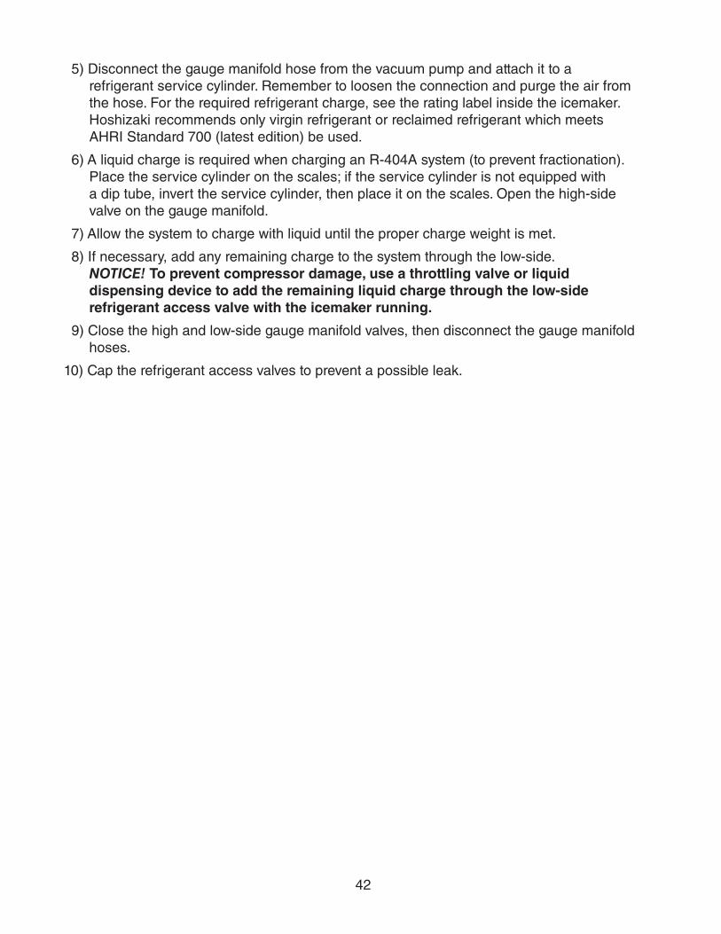
42
5) Disconnect the gauge manifold hose from the vacuum pump and attach it to a refrigerant service cylinder. Remember to loosen the connection and purge the air from the hose. For the required refrigerant charge, see the rating label inside the icemaker. Hoshizaki recommends only virgin refrigerant or reclaimed refrigerant which meets AHRI Standard 700 (latest edition) be used.
6) A liquid charge is required when charging an R-404A system (to prevent fractionation). Place the service cylinder on the scales; if the service cylinder is not equipped with a dip tube, invert the service cylinder, then place it on the scales. Open the high-side valve on the gauge manifold.
7) Allow the system to charge with liquid until the proper charge weight is met.
8) If necessary, add any remaining charge to the system through the low-side. NOTICE! To prevent compressor damage, use a throttling valve or liquid dispensing device to add the remaining liquid charge through the low-side refrigerant access valve with the icemaker running.
9) Close the high and low-side gauge manifold valves, then disconnect the gauge manifold hoses.
10) Cap the refrigerant access valves to prevent a possible leak.

43
B. Component Service Information
NOTICEWhen replacing a component listed below, see the notes to help ensure proper operation.
Component Notes
Compressor 1 phase: Install a new start capacitor, run capacitor, and start relay.3 phase: Install a new magnetic contactor.
Thermostatic Expansion Valves
• Attach the thermostatic expansion valve bulb to the suction line in the same location as the previous bulb.
• The bulb should be between the 10 and 2 o'clock positions on the tube.
• Secure the bulb with the clamp and holder, then insulate it.
Hot Gas ValvesLiquid Line Valves
• Replace the strainer if applicable.
• Use copper tube of the same diameter and length when replacing valve lines.
Fan Motors Install a new capacitor.
Pump Motor Install a new capacitor.
Thermistor • Attach the new thermistor to the suction line in the same location as the previous thermistor.
• The thermistor should be at the 12 o'clock position on the tube.
• Smoothly fill the recessed area of the thermistor holder with high thermal conductive type sealant. Hoshizaki America part number 4A0683-01 (Silicone Heat Sink Compound 10-8108 manufactured by GC Electronics), KE-4560 RTV (manufactured by ShinEtsu Silicones), or equivalent are recommended.
• Secure the thermistor with the holder, then insulate it.
• Be very careful to prevent damage to the leads.
C. Water Regulating Valve Adjustment (water-cooled model)The water regulating valve is factory set, and generally no adjustment is required. However, when necessary, adjust the water regulator using the following procedure.
1) Prepare a thermometer to check the condenser drain temperature. Attach a pressure gauge to the high-side line of the system.
2) 5 min. after a freeze cycle starts, confirm that the thermometer reads 104°F to 115°F (40°C to 46°C). If it does not, rotate the adjustment screw by using a flat blade screwdriver until the temperature is in the proper range. See Fig. 4. Next, check that the reference pressure is in the range indicated in the Head Pressure table in the Performance Data section. If it is not in the proper range, verify the refrigerant charge.
3) Check that the condenser drain temperature is stable.
Fig. 4
Adjustment Screw
CW – HigherCCW – Lower
Top View
44
V. Maintenance
The maintenance schedule below is a guideline. More frequent maintenance may berequired depending on water quality, the appliance's environment, and local sanitationregulations
WARNING• Only qualified service technicians should service the appliance.
• To reduce the risk of electric shock, do not touch the control switch or service switch with damp hands
• Before servicing: Move the control switch to the "OFF" position and turn off the power supply. Place the disconnect in the "OFF" position. Lockout/Tagout to prevent the power supply from being turned back on inadvertently.
• CHOKING HAZARD: Ensure all components, fasteners, and thumbscrews are securely in place after any maintenance is done to the icemaker. Make sure that none have fallen into the dispenser unit/ice storage bin.
Maintenance ScheduleFrequency Area Task
Daily Scoop Clean the ice scoop using a neutral cleaner. Rinse thoroughly after cleaning.
Bi-Weekly Air Filters Inspect. Wash with warm water and neutral cleaner if dirty.Monthly External Water
FiltersCheck for proper pressure and change if necessary.
Icemaker Exterior Wipe down with a clean, soft cloth. Use a damp cloth containing a neutral cleaner to wipe off oil or dirt build up. Clean any chlorine staining (rust colored spots) using a non-abrasive cleanser.
Underside of Icemaker and Top Kits; Bin Door and Snout
Wipe down with a clean cloth and warm water.
Yearly Icemaker and Dispenser Unit/Ice Storage Bin Liner
Clean and sanitize per the cleaning and sanitizing instructions provided in the instruction manual or maintenance label on the icemaker.
Water Supply Inlet Close the icemaker water supply line shut-off valve and drain the water system. Clean the water supply inlet screen.
Condenser Inspect. Clean if necessary by using a brush or vacuum cleaner. More frequent cleaning may be required depending on location.
Water Hoses Inspect the water hoses and clean/replace if necessary.

45
VI. Preparing the Appliance for Periods of Non-Use
NOTICE• When storing the appliance for an extended time or in sub-freezing temperatures,
follow the instructions below to prevent damage.
• The pump motor is energized continuously when the control switch is in the "SERVICE" position.
When the appliance is not used for two or three days under normal conditions, it is sufficient to move the control switch to the "OFF" position. When storing the appliance for an extended time or in sub-freezing temperatures, follow the instructions below.
1. Remove the water from the icemaker water line:
1) Turn off the power supply, then remove the front panel.
2) Move the control switch on the control box to the "OFF" position.
3) Close the icemaker water supply line shut-off valve, then open the icemaker water supply line drain valve.
4) Allow the line to drain by gravity.
5) Attach compressed air or carbon dioxide supply to the icemaker water supply line drain valve.
6) Make sure at least 3 min. have elapsed since you turned off the power supply. Move sure the control switch is in the "ICE" position.
7) Replace the front panel in its correct position, then turn on the power supply.
8) Blow the icemaker water supply line out using compressed air or carbon dioxide.
2. Drain the water tank:
1) Turn off the power supply, then remove the front panel.
2) Move the service switch to the "DRAIN" position, then move the control switch to the "SERVICE" position.
3) Replace the front panel in its correct position, then turn on the power supply for 2 minutes.
4) After 2 min., turn off the power supply, then remove the front panel.
5) Move the control switch to the "OFF" position.
6) Replace the front panel in its correct position.
7) Remove all ice from the dispenser unit/storage bin. Clean the dispenser unit/storage bin using a neutral cleaner. Rinse thoroughly after cleaning.
8) Close the icemaker water supply line drain valve.

46
3. On water-cooled model, remove the water from the water-cooled condenser:
1) Make sure the power supply is off, then remove the front panel and right side panel.
2) Close the condenser water supply line shut-off valve. If connected to a closed loop system, also close the condenser return line shut-off valve.
3) Open the condenser water supply line drain valve. If connected to a closed loop system, also open the condenser return line drain valve.
4) Attach a compressed air or carbon dioxide supply to the condenser water supply line drain valve.
5) Open the water regulating valve by using a screwdriver to pry up on the spring retainer underneath the spring. While holding the valve open, blow out the condenser using the compressed air or carbon dioxide supply until water stops coming out.
6) Close the drain valve(s).
7) Replace the right side panel and front panel in their correct positions.

47
VII. DisposalThe appliance contains refrigerant and must be disposed of in accordance with applicable national, state, and local codes and regulations. Refrigerant must be recovered by properly certified service personnel.

48
VIII. Technical InformationWe reserve the right to make changes in specifications and design without prior notice.
A. Specification and Performance Data SheetsPressure data is recorded at 5 min. into freezing cycle. The data not in bold should be used for reference only.
1. KML-325MAJ
Specification SheetAC SUPPLY VOLTAGE 115/60/1 AMPERAGE 8.4 A (5 Min. Freeze AT 104°F / WT 80°F)MINIMUM CIRCUIT AMPACITY 15 AMAXIMUM FUSE SIZE 15 AELECTRIC & WATER CONSUMPTION 90/70°F 70/50°F ELECTRIC W (kWH/100 lbs.) 720 (5.72) 710 (4.51) WATER gal./24HR (gal./100 lbs.) 60 (19.9) 161 (42.3)ICE PRODUCTION PER CYCLE 8.1 lbs. (3.7 kg) 360pcs.BIN CONTROL SYSTEM ThermostatREFRIGERANT CHARGE R404A, 1 lb. 5.2 oz. (600g)
Performance Data Sheet
70/21 380 172 357 162 331 15080/27 362 164 326 148 304 13870/2180/2790/32
watts 100/3870/21 161 0.61 131 0.50 114 0.4380/27 138 0.52 92 0.35 88 0.3390/32 131 0.50 60 0.23 50 0.19
gal./day m3/day 100/38 97 0.37 57 0.22 41 0.1570/2180/2790/32
min. 100/3870/2180/2790/32
min. 100/3870/21 213 15.0 229 16.1 266 18.780/27 225 15.8 250 17.6 296 20.890/32 229 16.1 267 18.8 310 21.8
PSIG kg/cm2G 100/38 242 17.0 277 19.5 350 24.670/21 55 3.9 56 3.9 58 4.180/27 56 3.9 57 4.0 59 4.290/32 56 3.9 58 4.1 60 4.2
PSIG kg/cm2G 100/38 56 4.0 58 4.1 62 4.4
5,800 BTU/h [AT 90ºF (32ºC) / WT 70ºF (21ºC)]TOTAL HEAT OF REJECTION FROM COMPRESSOR 900 BTU/h [AT 90ºF (32ºC) / WT 70ºF (21ºC)]
2.8 2.1 2.1HEAD PRESSURE
SUCTION PRESSURE
TOTAL HEAT OF REJECTION FROM CONDENSER
HARVEST CYCLE TIME 4.0 3.4 3.23.6 2.7 2.83.4 2.1 2.1
3529 33 3729 34 40
716 722 740APPROXIMATE WATER CONSUMPTION PER 24 HR.
FREEZING CYCLE TIME 26 29 3228 31
APPROXIMATE ELECTRIC CONSUMPTION
710 713 722712 717 728713 720 730
APPROXIMATE ICE PRODUCTION PER 24 HR.
AMBIENT TEMP. (ºF/ºC)
WATER TEMP. (ºF/ºC)50/10 70/21 90/32
ENG.F-011.1.0205

49
2. KML-325MWJ
Specification SheetAC SUPPLY VOLTAGE 115/60/1 AMPERAGE 8.4 A (5 Min. Freeze AT 104°F / WT 80°F)MINIMUM CIRCUIT AMPACITY 15 AMAXIMUM FUSE SIZE 15 AELECTRIC & WATER CONSUMPTION 90/70°F 70/50°F ELECTRIC W (kWH/100 lbs.) 670 (4.51) 690 (4.31) WATER gal./24HR (gal./100 lbs.) 60 (17.0) 122 (31.6) WATER COOLED CONDENSER 376 (106) 155 (40) gal./24HR (gal./100 lbs.)ICE PRODUCTION PER CYCLE 7.9 lbs. (3.6 kg) 360pcs.BIN CONTROL SYSTEM ThermostatREFRIGERANT CHARGE R404A, 1 lb. 1.6 oz. (500g)
Performance Data Sheet
70/21 385 175 376 171 362 16480/27 378 172 365 165 349 15890/32 376 171 355 161 339 154
lbs./day kg./day 100/38 372 169 351 159 325 14770/2180/2790/32
watts 100/3870/21 277 1.05 324 1.23 406 1.5480/27 313 1.18 385 1.46 478 1.8190/32 324 1.23 437 1.65 527 1.99
gal./day m3/day 100/38 402 1.52 458 1.73 610 2.3170/2180/2790/32
min. 100/3870/2180/2790/32
min. 100/3870/21 267 18.8 268 18.8 272 19.280/27 267 18.8 268 18.9 275 19.490/32 268 18.8 269 18.9 275 19.4
PSIG kg/cm2G 100/38 270 19.0 270 19.0 281 19.870/21 56 3.9 56 3.9 56 4.080/27 56 3.9 55 3.9 57 4.090/32 56 3.9 55 3.9 56 3.9
PSIG kg/cm2G 100/38 56 4.0 55 3.9 57 4.0
5,500 BTU/h [AT 90ºF (32ºC) / WT 70ºF (21ºC)]TOTAL HEAT OF REJECTION FROM COMPRESSOR 900 BTU/h [AT 90ºF (32ºC) / WT 70ºF (21ºC)]WATER FLOW FOR CONDENSER 23 gal./h [AT 100ºF (38ºC) / WT 90ºF (32ºC)]PRESSURE DROP OF COOLING WATER LINE less than 10 PSIG
2.5 2.1 2.0HEAD PRESSURE
SUCTION PRESSURE
TOTAL HEAT OF REJECTION FROM CONDENSER
HARVEST CYCLE TIME 3.3 2.9 2.83.0 2.5 2.52.9 2.1 2.1
2527 29 2626 28 24
682 668 650APPROXIMATE WATER CONSUMPTION PER 24 HR.
FREEZING CYCLE TIME 26 27 2527 28
APPROXIMATE ELECTRIC CONSUMPTION
690 684 674686 676 666684 670 660
APPROXIMATE ICE PRODUCTION PER 24 HR.
AMBIENT TEMP. (ºF/ºC)
WATER TEMP. (ºF/ºC)50/10 70/21 90/32
ENG.F-011.1.0205

50
3. KML-500MAJSpecification SheetAC SUPPLY VOLTAGE 115/60/1 AMPERAGE 7.6 A ( 5 Min. Freeze AT 104°F / WT 80°F)MINIMUM CIRCUIT AMPACITY 20 AMAXIMUM FUSE SIZE 20 AELECTRIC & WATER CONSUMPTION 90/70°F 70/50°F ELECTRIC W (kWH/100 lbs.) 930 (5.55) 850 (4.64) WATER gal./24HR (gal./100 lbs.) 64 (16.0) 143 (32.4)ICE PRODUCTION PER CYCLE 7.9 lbs. (3.6 kg) 360pcs.BIN CONTROL SYSTEM ThermostatREFRIGERANT CHARGE R404A, 1 lb. 10.5 oz. (750g)
Performance Data Sheet
70/21 442 200 430 195 399 18180/27 433 196 413 188 376 17070/2180/2790/32
watts 100/3870/21 143 0.54 120 0.45 107 0.4080/27 126 0.48 89 0.34 87 0.3390/32 120 0.45 64 0.24 57 0.21
gal./day m3/day 100/38 93 0.35 62 0.24 50 0.1970/2180/2790/32
min. 100/3870/2180/2790/32
min. 100/3870/21 250 17.6 268 18.9 289 20.380/27 264 18.6 293 20.6 310 21.890/32 268 18.9 313 22.0 332 23.4
PSIG kg/cm2G 100/38 271 19.0 318 22.3 350 24.670/21 57 4.0 58 4.0 59 4.180/27 57 4.0 58 4.1 60 4.290/32 58 4.0 59 4.1 61 4.3
PSIG kg/cm2G 100/38 58 4.1 59 4.2 62 4.4
6,200 BTU/h [AT 90ºF (32ºC) / WT 70ºF (21ºC)]TOTAL HEAT OF REJECTION FROM COMPRESSOR 1,200 BTU/h [AT 90ºF (32ºC) / WT 70ºF (21ºC)]
2.6 2.0 2.1HEAD PRESSURE
SUCTION PRESSURE
TOTAL HEAT OF REJECTION FROM CONDENSER
HARVEST CYCLE TIME 3.5 3.1 2.93.2 2.5 2.63.1 2.0 2.0
2724 26 2824 27 30
867 930 930APPROXIMATE WATER CONSUMPTION PER 24 HR.
FREEZING CYCLE TIME 23 24 2523 25
APPROXIMATE ELECTRIC CONSUMPTION
850 873 881868 904 898873 930 930
APPROXIMATE ICE PRODUCTION PER 24 HR.
AMBIENT TEMP. (ºF/ºC)
WATER TEMP. (ºF/ºC)50/10 70/21 90/32
ENG.F-011.1.0205

51
4. KML-500MWJ
Specification SheetAC SUPPLY VOLTAGE 115/60/1 AMPERAGE 9.6 A (5 Min. Freeze AT 104°F / WT 80°F)MINIMUM CIRCUIT AMPACITY 20 AMAXIMUM FUSE SIZE 20 AELECTRIC & WATER CONSUMPTION 90/70°F 70/50°F ELECTRIC W (kWH/100 lbs.) 930 (4.33) 890 (3.93) WATER gal./24HR (gal./100 lbs.) 82 (16.0) 125 (22.9) WATER COOLED CONDENSER 567 (110) 279 (51) gal./24HR (gal./100 lbs.)ICE PRODUCTION PER CYCLE 7.9 lbs. (3.6 kg) 360pcs.BIN CONTROL SYSTEM ThermostatREFRIGERANT CHARGE R404A, 0 lb. 15.9 oz. (450g)
Performance Data Sheet
70/21 543 246 535 243 515 23380/27 537 243 524 238 499 22690/32 535 243 515 234 492 223
lbs./day kg./day 100/38 528 239 510 231 470 21370/2180/2790/32
watts 100/3870/21 403 1.53 475 1.80 584 2.2180/27 458 1.73 570 2.16 684 2.5990/32 475 1.80 649 2.46 763 2.89
gal./day m3/day 100/38 588 2.23 676 2.56 868 3.2970/2180/2790/32
min. 100/3870/2180/2790/32
min. 100/3870/21 275 19.3 276 19.4 277 19.580/27 276 19.4 278 19.6 279 19.690/32 276 19.4 280 19.7 281 19.7
PSIG kg/cm2G 100/38 276 19.4 280 19.7 281 19.870/21 57 4.0 57 4.0 57 4.080/27 57 4.0 57 4.0 57 4.090/32 57 4.0 57 4.0 57 4.0
PSIG kg/cm2G 100/38 57 4.0 57 4.0 57 4.0
8,000 BTU/h [AT 90ºF (32ºC) / WT 70ºF (21ºC)]TOTAL HEAT OF REJECTION FROM COMPRESSOR 1,400 BTU/h [AT 90ºF (32ºC) / WT 70ºF (21ºC)]WATER FLOW FOR CONDENSER 33 gal./h [AT 100ºF (38ºC) / WT 90ºF (32ºC)]PRESSURE DROP OF COOLING WATER LINE less than 10 PSIG
2.3 2.0 2.0HEAD PRESSURE
SUCTION PRESSURE
TOTAL HEAT OF REJECTION FROM CONDENSER
HARVEST CYCLE TIME 2.6 2.5 2.42.5 2.2 2.32.5 2.1 2.0
2119 20 2119 21 23
900 931 940APPROXIMATE WATER CONSUMPTION PER 24 HR.
FREEZING CYCLE TIME 18 19 2019 20
APPROXIMATE ELECTRIC CONSUMPTION
890 902 909899 917 920902 930 935
APPROXIMATE ICE PRODUCTION PER 24 HR.
AMBIENT TEMP. (ºF/ºC)
WATER TEMP. (ºF/ºC)50/10 70/21 90/32
ENG.F-011.1.0205

52
5. KML-700MAJSpecification SheetAC SUPPLY VOLTAGE 115/60/1 AMPERAGE 14.2 A (5 Min. Freeze AT 104°F / WT 80°F)MINIMUM CIRCUIT AMPACITY 20 AMAXIMUM FUSE SIZE 20 AELECTRIC & WATER CONSUMPTION 90/70°F 70/50°F ELECTRIC W (kWH/100 lbs.) 1230 (5.16) 1120 (4.10) WATER gal./24HR (gal./100 lbs.) 92 (16.0) 223 (33.9)ICE PRODUCTION PER CYCLE 10.4 lbs. (4.7 kg) 480pcs.BIN CONTROL SYSTEM ThermostatREFRIGERANT CHARGE R404A, 2 lb. 10.3 oz. (1200g)
Performance Data Sheet
70/21 658 298 633 287 588 26780/27 639 290 600 272 549 24970/2180/2790/32
watts 100/3870/21 223 0.84 185 0.70 166 0.6380/27 194 0.73 134 0.51 134 0.5190/32 185 0.70 92 0.35 84 0.32
gal./day m3/day 100/38 141 0.53 90 0.34 76 0.2970/2180/2790/32
min. 100/3870/2180/2790/32
min. 100/3870/21 258 18.1 275 19.3 303 21.380/27 271 19.1 297 20.9 328 23.190/32 275 19.3 316 22.2 346 24.3
PSIG kg/cm2G 100/38 282 19.8 323 22.7 374 26.370/21 54 3.8 56 3.9 57 4.080/27 56 3.9 59 4.1 58 4.190/32 56 3.9 61 4.3 61 4.3
PSIG kg/cm2G 100/38 55 3.9 61 4.3 61 4.3
11,300 BTU/h [AT 90ºF (32ºC) / WT 70ºF (21ºC)]TOTAL HEAT OF REJECTION FROM COMPRESSOR 1,500 BTU/h [AT 90ºF (32ºC) / WT 70ºF (21ºC)]
2.7 2.1 2.1HEAD PRESSURE
SUCTION PRESSURE
TOTAL HEAT OF REJECTION FROM CONDENSER
HARVEST CYCLE TIME 3.6 3.1 3.03.2 2.5 2.73.1 2.1 2.1
2621 25 2722 25 29
1164 1242 1330APPROXIMATE WATER CONSUMPTION PER 24 HR.
FREEZING CYCLE TIME 20 21 2421 23
APPROXIMATE ELECTRIC CONSUMPTION
1120 1152 12021145 1195 12471152 1230 1282
APPROXIMATE ICE PRODUCTION PER 24 HR.
AMBIENT TEMP. (ºF/ºC)
WATER TEMP. (ºF/ºC)50/10 70/21 90/32
ENG.F-011.1.0205

53
6. KML-700MWJ
Specification SheetAC SUPPLY VOLTAGE 115/60/1 AMPERAGE 12.6 A (5 Min. Freeze AT 104°F / WT 80°F)MINIMUM CIRCUIT AMPACITY 20 AMAXIMUM FUSE SIZE 20 AELECTRIC & WATER CONSUMPTION 90/70°F 70/50°F ELECTRIC W (kWH/100 lbs.) 1100 (3.61) 1070 (3.40) WATER gal./24HR (gal./100 lbs.) 117 (16.0) 181 (24.0) WATER COOLED CONDENSER 810 (111) 454 (60) gal./24HR (gal./100 lbs.)ICE PRODUCTION PER CYCLE 10.7 lbs. (4.8 kg) 480pcs.BIN CONTROL SYSTEM ThermostatREFRIGERANT CHARGE R404A, 1 lb. 6 oz. (625g)
Performance Data Sheet
70/21 756 343 748 339 688 31280/27 750 340 738 335 651 29590/32 748 339 730 331 653 296
lbs./day kg./day 100/38 720 326 712 323 582 26470/2180/2790/32
watts 100/3870/21 635 2.40 721 2.73 1336 5.0680/27 700 2.65 833 3.15 1725 6.5390/32 721 2.73 927 3.51 1715 6.49
gal./day m3/day 100/38 1062 4.02 1112 4.21 2439 9.2370/2180/2790/32
min. 100/3870/2180/2790/32
min. 100/3870/21 237 16.7 238 16.7 240 16.980/27 238 16.7 239 16.8 242 17.090/32 238 16.7 240 16.9 243 17.1
PSIG kg/cm2G 100/38 239 16.8 241 16.9 246 17.370/21 58 4.1 59 4.1 59 4.280/27 58 4.1 59 4.2 60 4.290/32 59 4.1 60 4.2 61 4.3
PSIG kg/cm2G 100/38 59 4.1 60 4.2 61 4.3
12,600 BTU/h [AT 90ºF (32ºC) / WT 70ºF (21ºC)]TOTAL HEAT OF REJECTION FROM COMPRESSOR 1,500 BTU/h [AT 90ºF (32ºC) / WT 70ºF (21ºC)]WATER FLOW FOR CONDENSER 98 gal./h [AT 100ºF (38ºC) / WT 90ºF (32ºC)]PRESSURE DROP OF COOLING WATER LINE less than 10 PSIG
2.4 2.1 2.1HEAD PRESSURE
SUCTION PRESSURE
TOTAL HEAT OF REJECTION FROM CONDENSER
HARVEST CYCLE TIME 2.9 2.7 2.62.7 2.3 2.42.7 2.1 2.1
2018 19 2018 19 21
1080 1102 1120APPROXIMATE WATER CONSUMPTION PER 24 HR.
FREEZING CYCLE TIME 18 18 1918 19
APPROXIMATE ELECTRIC CONSUMPTION
1070 1079 10891077 1090 11001079 1100 1110
APPROXIMATE ICE PRODUCTION PER 24 HR.
AMBIENT TEMP. (ºF/ºC)
WATER TEMP. (ºF/ºC)50/10 70/21 90/32
ENG.F-011.1.0205

54
7. KML-700MRJSpecification SheetAC SUPPLY VOLTAGE 115/60/1 AMPERAGE 16.0 A (5 Min. Freeze AT 104°F / WT 80°F)MINIMUM CIRCUIT AMPACITY 20 AMAXIMUM FUSE SIZE 20 AELECTRIC & WATER CONSUMPTION 90/70°F 70/50°F ELECTRIC W (kWH/100 lbs.) 1260 (4.70) 1170 (3.78) WATER gal./24HR (gal./100 lbs.) 103 (16.0) 143 (19.3)ICE PRODUCTION PER CYCLE 10.5 lbs. (4.8 kg) 480pcs.BIN CONTROL SYSTEM ThermostatREFRIGERANT CHARGE TOTAL R404A, 11 lb. 7.4 oz. (5200g)
ICEMAKER, 7 lb. 8.6 oz. (3420g)CONDENSER, 3 lb. 14.8 oz. (1780g)
Performance Data Sheet
90/32 713 323 643 292 602 273lbs./day kg./day 100/38 705 320 633 287 565 256
70/2180/2790/32
watts 100/3870/21 143 0.54 131 0.50 123 0.4680/27 134 0.51 116 0.44 111 0.4290/32 131 0.50 103 0.39 96 0.36
gal./day m3/day 100/38 117 0.44 101 0.38 90 0.3470/2180/2790/32
min. 100/3870/2180/2790/32
min. 100/3870/21 204 14.3 220 15.5 239 16.880/27 217 15.2 242 17.0 259 18.290/32 220 15.5 260 18.3 278 19.6
PSIG kg/cm2G 100/38 223 15.7 264 18.6 295 20.770/21 52 3.7 54 3.8 57 4.080/27 54 3.8 57 4.0 60 4.290/32 54 3.8 60 4.2 63 4.4
PSIG kg/cm2G 100/38 55 3.8 61 4.3 65 4.6
11,200 BTU/h [AT 90ºF (32ºC) / WT 70ºF (21ºC)]TOTAL HEAT OF REJECTION FROM COMPRESSOR 1,500 BTU/h [AT 90ºF (32ºC) / WT 70ºF (21ºC)]
2.2 2.1 2.1HEAD PRESSURE
SUCTION PRESSURE
TOTAL HEAT OF REJECTION FROM CONDENSER
HARVEST CYCLE TIME 2.4 2.3 2.32.4 2.2 2.22.3 2.2 2.1
2219 21 2319 22 25
1195 1264 1290APPROXIMATE WATER CONSUMPTION PER 24 HR.
FREEZING CYCLE TIME 18 19 2119 20
APPROXIMATE ELECTRIC CONSUMPTION
1170 1196 12171190 1231 12431196 1260 1276
APPROXIMATE ICE PRODUCTION PER 24 HR.
AMBIENT TEMP. (ºF/ºC)
WATER TEMP. (ºF/ºC)50/10 70/21 90/32
ENG.F-011.1.0205

55
@
B. Wiring Diagram
1. KML-325M_J, KML-500M_J, KML-700M_J
* H
igh-
Pre
ssur
e S
witc
h
Air-
Coo
led
Mod
elW
ater
-Coo
led
Mod
el
Cut
-out
412±
22 P
SIG
384±
22 P
SIG
Cut
-in
327±
22 P
SIG
284±
22 P
SIG
00
*