HOSHIZAKI MODULAR FLAKER-C)_serv.pdfHOSHIZAKI MODULAR FLAKER NO: 73122 MODEL FS-1001MLH/-C ALSO...
55
SERVICE MANUAL ISSUED: September 12, 2005 HOSHIZAKI MODULAR FLAKER NO: 73122 MODEL FS-1001MLH/-C ALSO COVERS HOSHIZAKI CONDENSING UNIT MODEL SRC-10H
Transcript of HOSHIZAKI MODULAR FLAKER-C)_serv.pdfHOSHIZAKI MODULAR FLAKER NO: 73122 MODEL FS-1001MLH/-C ALSO...

SERVICE MANUAL
ISSUED:September 12, 2005
HOSHIZAKIMODULAR FLAKER
NO: 73122
MODEL
FS-1001MLH/-CALSO COVERS
HOSHIZAKI CONDENSING UNITMODEL SRC-10H

2
HOSHIZAKI AMERICA, INC.618 Highway 74 SouthPeachtree City, GA 30269
Attn: HOSHIZAKI Technical Support Department
Phone: 1-800-233-1940 Technical Service (770) 487-2331
Fax: 1-800-843-1056 (770) 487-3360
Web Site: www.hoshizakiamerica.com
NOTE: To expedite assistance, all correspondence/communication MUST include thefollowing information:
• Model Number
• Serial Number
• Complete and detailed explanation of the problem
IMPORTANTOnly qualified service technicians should attempt to service or maintain thisicemaker. No such service or maintenance should be undertaken until thetechnician has thoroughly read this Service Manual.
HOSHIZAKI provides this manual primarily to assist qualified service technicians in theservice and maintenance of the icemaker.
Should the reader have any questions or concerns which have not been satisfactorilyaddressed, please call or write to the HOSHIZAKI Technical Support Department forassistance.
3
Please review this manual. It should be read carefully before the icemaker is serviced ormaintenance operations are performed. Only qualified service technicians should serviceand maintain the icemaker. This manual should be made available to the technician prior toservice or maintenance.
CONTENTSI. Specifications .................................................................................................................... 5
A. Icemaker ...................................................................................................................... 51. FS-1001MLH .......................................................................................................... 52. FS-1001MLH-C ...................................................................................................... 6
B. Condensing Unit .......................................................................................................... 71. SRC-10H ................................................................................................................ 7
II. General Information .......................................................................................................... 8A. Dimensions .................................................................................................................. 8
1. Icemaker ................................................................................................................. 8a) FS-1001MLH/-C ................................................................................................ 8
2. Condensing Unit ..................................................................................................... 9a) SRC-10H .......................................................................................................... 9
B. Construction ............................................................................................................... 101. Icemaker ............................................................................................................... 10
a) FS-1001MLH/-C .............................................................................................. 102. Condensing Unit ................................................................................................... 11
a) SRC-10H ........................................................................................................ 11C. Control Box Layout .................................................................................................... 12
1. Icemaker ............................................................................................................... 12a) FS-1001MLH/-C .............................................................................................. 12
2. Condensing Unit ................................................................................................... 13a) SRC-10H ........................................................................................................ 13
III. Technical Information ..................................................................................................... 14A. Water Circuit and Refrigeration Circuit ....................................................................... 14
1. Icemaker ............................................................................................................... 14a) FS-1001MLH/-C .............................................................................................. 14
2. Condensing Unit ................................................................................................... 15a) SRC-10H ........................................................................................................ 15
B. Wiring Diagram .......................................................................................................... 161. Icemaker ............................................................................................................... 16
a) FS-1001MLH/-C .............................................................................................. 162. Condensing Unit ................................................................................................... 17
a) SRC-10H ........................................................................................................ 17C. Sequence of Electrical Circuit .................................................................................... 18
1. Icemaker ............................................................................................................... 18D. Timing Chart .............................................................................................................. 27E. Performance Data ...................................................................................................... 30
1. FS-1001MLH ........................................................................................................ 302. FS-1001MLH-C .................................................................................................... 31

4
IV. Service Diagnosis .......................................................................................................... 32A. No Ice Production ...................................................................................................... 32
1. Icemaker ............................................................................................................... 322. Condensing Unit ................................................................................................... 34
B. Low Ice Production .................................................................................................... 34C. Other .......................................................................................................................... 35
V. Removal and Replacement of Components ................................................................... 36A. Service for Refrigerant Lines ...................................................................................... 36
1. Refrigerant Recovery ........................................................................................... 362. Evacuation and Recharge [R-404A] ..................................................................... 36
a) Complete ......................................................................................................... 36b) Partial evacuation with pumpdown ................................................................. 37
B. Brazing ....................................................................................................................... 38C. Service for Condensing Unit ...................................................................................... 39
1. Removal and Replacement of Compressor .......................................................... 392. Removal and Replacement of Condensing Pressure Regulator (C.P.R.) ............. 40
D. Removal and Replacement of Drier ........................................................................... 41E. Removal and Replacement of Expansion Valve ........................................................ 42F. Removal and Replacement of Evaporator Assembly ................................................. 43G. Removal and Replacement of Control Water Valve ................................................... 47H. Removal and Replacement of Flush Water Valve ...................................................... 48
VI. Cleaning and Maintenance ........................................................................................... 49A. Preparing the Icemaker for Long Storage ................................................................... 49B. Cleaning and Sanitizing Instructions.......................................................................... 50
1. Cleaning Solution ................................................................................................. 502. Cleaning Procedure ............................................................................................. 503. Sanitizing Solution ............................................................................................... 524. Sanitizing Procedure - Initial ................................................................................. 525. Sanitizing Procedure - Final ................................................................................. 53
C. Maintenance Instructions ........................................................................................... 55

5
I. SpecificationsA. Icemaker
1. FS-1001MLH
We reserve the right to make changes in specifications and design without prior notice.
No Data Available

6
2. FS-1001MLH-C
We reserve the right to make changes in specifications and design without prior notice.
AC SUPPLY VOLTAGE 115/60/1GEAR MOTOR 120 V 3 FLA 1/4 HPOTHER 120 V 0.03AMAXIMUM FUSE SIZE 15 AMAX. HACR BREAKER (USA ONLY) 15 AMAX. CIRC. BREAKER (CANADA ONLY) 15 AMINIMUM CIRCUIT AMPACITY 15 AAPPROXIMATE ICE PRODUCTION Ambient WATER TEMP. (°F)PER 24 HR. Temp.(°F) 50 70 90 lbs./day ( kg/day ) 70 *830 (380) 805 (365) 785 (355)Reference without *marks 80 765 (350) 750 (340) 730 (330)
90 710 (325) *705 (320) 680 (310)100 660 (300) 650 (295) *600 (275)
SHAPE OF ICE CubeletICE QUALITY Approx. 80%, Ice (90/70°F, Conductivity 200 µs/cm)APPROXIMATE STORAGE CAPACITY N/AELECTRIC & WATER CONSUMPTION 90/70°F 70/50°F ELECTRIC W (kWH/100 lbs.) 1745 (5.96) 1713 (4.94) FS-1001MLH-C & SRC-10H ELECTRIC W (kWH/100 lbs.) 331 (1.13) 345 (1.00) FS-1001MLH-C ONLY POTABLE WATER 84 (12) 100 (12) gal./24HR (gal./100 lbs.)EXTERIOR DIMENSIONS (WxDxH) 30" x 11" x 26" (766 x 279 x 660mm)EXTERIOR FINISH Stainless Steel WEIGHT Net 126 lbs. ( 57 kg ), Shipping 166 lbs. ( 75 kg )CONNECTIONS - ELECTRIC Cord Connection - WATER SUPPLY Inlet 1/2" FPT - DRAIN Outlet 3/4" FPT - REFRIGERATION Suction line 1-1/16-12 UNF Fitting (#10 AEROQUIP) CIRCUIT Liquid line 5/8-18 UNF Fitting (#6 AEROQUIP)ICE MAKING SYSTEM Auger typeHARVESTING SYSTEM Direct Driven Auger ( 1/4 HP Gear Motor )ICE MAKING WATER CONTROL Float SwitchCOOLING WATER CONTROL N/ABIN CONTROL SYSTEM (Primary) Photoelctric SensorBIN CONTROL SYSTEM (Secondary) Mechanical Bin Control ( Proximity Sw. )CONDENSING UNIT Air-cooled Remote Condensing unit SRC-10H RequiredEVAPORATOR Copper Tube on CylinderREFRIGERANT CONTROL Thermostatic Expansion Valve
Condensing Pressure Regulator on SRC-10HREFRIGERANT CHARGE R-404A, 8 lb.6oz. (3800g)
(Ice Maker: 4 oz., Cond. Unit: 8 lb. 2 oz. )DESIGN PRESSURE High 427 PSIG, Low 230 PSIGP.C. BOARD CIRCUIT PROTECTION Fuse (1A)GEAR MOTOR PROTECTION Fuse (3A)LOW WATER PROTECTION Float Switch and TimerACCESSORIES -SUPPLIED Spare Fuse -REQUIRED Ice Storage BinOPERATING CONDITIONS VOLTAGE RANGE 104-127 V
AMBIENT TEMP. 45-100° FWATER SUPPLY TEMP. 45-90° FWATER SUPPLY PRESSURE 10-113 PSIG

7
B. Condensing Unit1. SRC-10H
We reserve the right to make changes in specifications and design without prior notice.
AC SUPPLY VOLTAGE 208-230/60/1 (3 WIRE W/ NEUTRAL FOR 115V)COMPRESSOR 208-230 9.6 RLA 46 LRAFAN MOTOR 120 V 3 A MAXOTHER 120 V 0.5 AMAXIMUM FUSE SIZE 20 AMAX. HACR BREAKER (USA ONLY) 20 AMAX. CIRC. BREAKER (CANADA ONLY) 20 AMINIMUM CIRCUIT AMPACITY 20 AEXTERIOR DIMENSIONS (WxDxH) 28-1/4" x 23" x 19-7/8" (717 x 584 x 506mm)DIMENSIONS WITH LEGS (WxDxH) 30-1/4" x 25-3/8" x 34-7/8" (770 x 645 x 886mm)EXTERIOR FINISH Galvanized SteelWEIGHT (approximate) Net 143 lbs. ( 65 kg ), Shipping 169 lbs. ( 77 kg )CONNECTIONS - ELECTRIC Permanent - Connection - REFRIGERATION Discharge line 1-1/16-12 UNF Fitting (#10 AEROQUIP) CIRCUIT Liquid line 5/8-18 UNF Fitting (#6 AEROQUIP)COMPRESSOR Hermetic, Model RS80-C2E-CAVCONDENSER Air-cooled fin and tube typeFAN MOTOR PROTECTION Thermal ProtectorREFRIGERATION PROTECTION Auto-reset High Pressure Switch, Manual low Pressure SwitchREFRIGERANT CONTROL Condenser Pressure RegulatorPUMPDOWN CONTROL Auto-reset Low Pressure SwitchREFRIGERANT CHARGE R-404A, 8 lb.6oz. (3800g)
(Ice Maker: 4 oz., Cond. Unit: 8 lb. 2 oz. )DESIGN PRESSURE High 427 PSIG, Low 230 PSIGCOMPRESSOR PROTECTION Internal ProtectorACCESSORIES -SUPPLIED Leg 2 pcs.
Hex. Head Bolt w/ Washer 8X16 8 pcs.Hex. Nut 8 pcs.
OPERATING CONDITIONS VOLTAGE RANGE 187-253 VAMBIENT TEMP. -4-122° FHEAT OF REJECTION 10500 BTU/hr
8
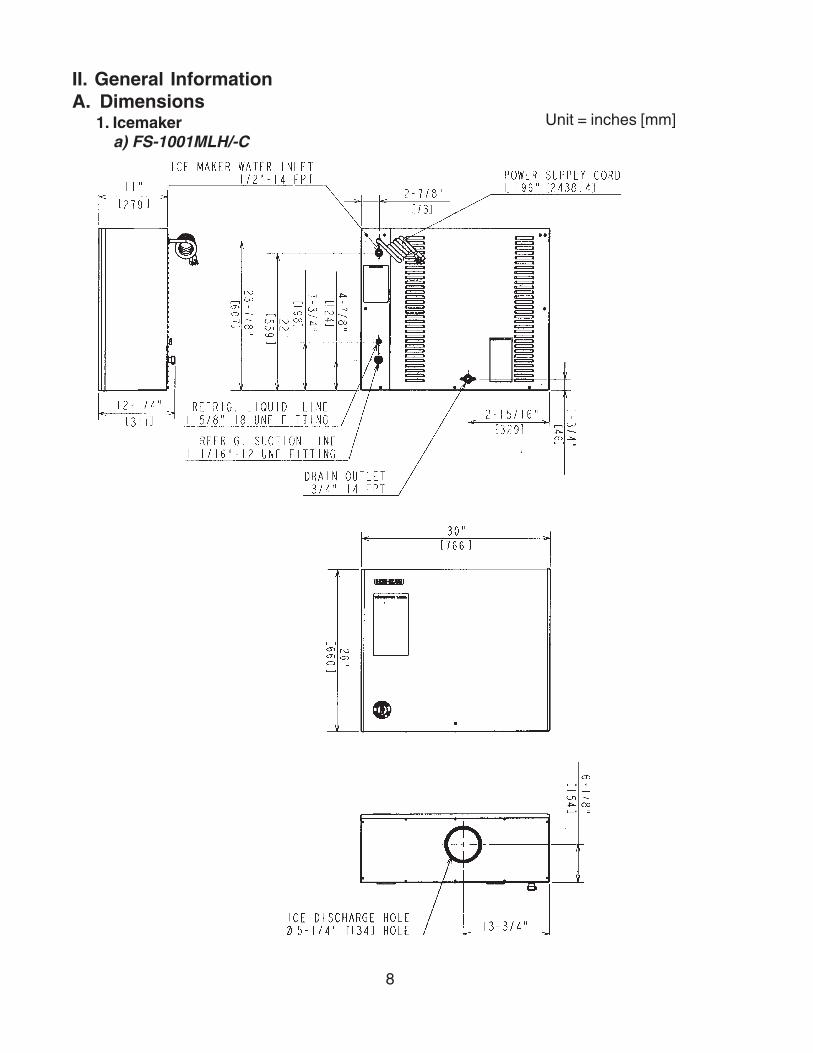
II. General InformationA. Dimensions
1. Icemakera) FS-1001MLH/-C
Unit = inches [mm]

9
2. Condensing Unita) SRC-10H
Unit = [inches] mm

10
B. Construction1. Icemaker
a) FS-1001MLH/-C
Drier
Ice Chute
Control WaterValve
Water SupplyInlet
Evaporator
Gear Motor
Flush WaterValve
Control Box
Bin Control
Power SupplyCord
ExpansionValve
Beam Sensor

11
2. Condensing Unita) SRC-10H
Control Box
Condenser
Receiver Tank
Compressor
Fan Motor
Condenser PressureRegulator

12
C. Control Box Layout1. Icemaker
a) FS-1001MLH/-C
Water ControlRelay
Gear MotorRelay
Connector
FlushSwitch
PowerSwitch
Fuse(Timer Board 1A)
Fuse(Gear Motor 3A)
TransformerCapacitor
CamTimer
Connector
Timer BoardTime DelayRelay

13
2. Condensing Unita) SRC-10H
Capacitor
Starter (Relay) Magnetic Contactor
Capacitor - Start
Capacitor - Run
Low Pressure Switch 1 (Control)Cut-out 9 psigCut-in 29 psig
Low Pressure Switch 2 (Safety)Cut-out 3 psigCut-in 6 psig (manual reset)
PressureSwitch

14
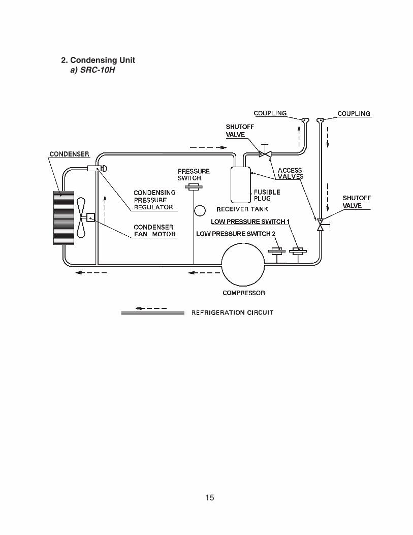
III. Technical InformationA. Water Circuit and Refrigeration Circuit
1. Icemakera) FS-1001MLH/-C
15
2. Condensing Unita) SRC-10H
16
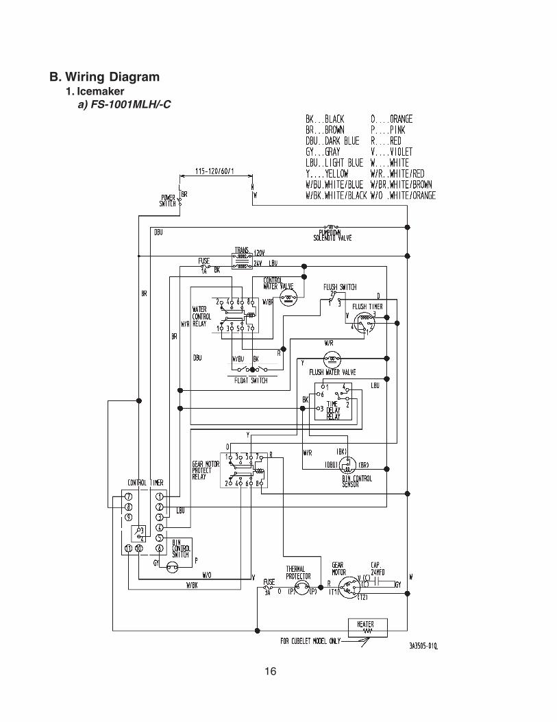
B. Wiring Diagram1. Icemaker
a) FS-1001MLH/-C
17
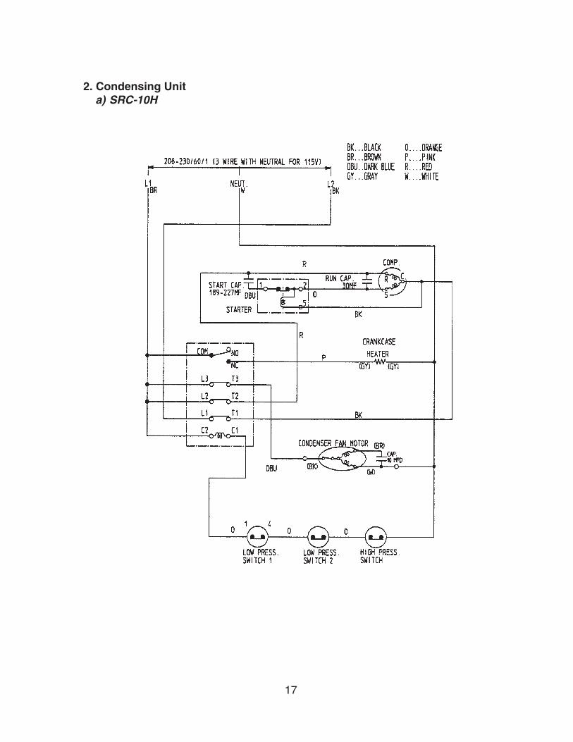
2. Condensing Unita) SRC-10H

18
C. Sequence of Electrical Circuit1. Icemaker
1. When the power switch is moved to the “ON” position and the flush switch to the “ICE”position, water starts to be supplied to the reservoir.

19
2. When the reservoir has been filled, the gear motor starts immediately.

20
3. The pumpdown solenoid valve energizes about 60 sec. after the gear motor starts.

21
4a. The bin control sensor operates and the pumpdown solenoid deenergizes after atime delay set by the user. 60 seconds after that the gear motor stops.

22
4b. Should the bin control sensor fail and the bin control switch operate, the pumpdownsolenoid valve and gear motor will stop simultaneously 6 sec. after operation.
23
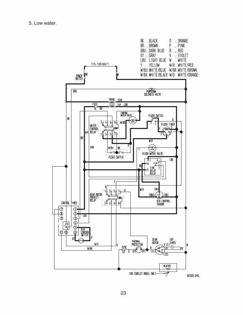
5. Low water.

24
6. When the flush switch is moved to the “FLUSH” position, the flush water valve opens andflushes the reservoir and evaporator.

25
7. When the flush timer operates (for 15 min. every 12 hours).

26
8. If the gear motor fuse (3A) blows, the solenoid valve and gear motor will turn off immediately.

27
D. Timing Chart
On2. Off
OnOff
3. OnOff
4. OnOff
5. 1 - 22 - 3
6. FlushIce
7. OnOff
8. Bin Control OnOff
1 sec 6 sec
9. OnOff
10. OnOff
11. OnOff
60 sec 60 sec
12. OnOff
13. Heater OnOff
UpperLowerBottom
1.
Water Control Relay
Control Water Valve
Upper
Lower
Water Level
Float Switch
1 sec
Bin Control Switch Off On
Flush Timer
Flush Switch
Flush Water Valve
Gear Motor
Fan Motor
Pumpdown Solenoid
Gear Motor Relay
28
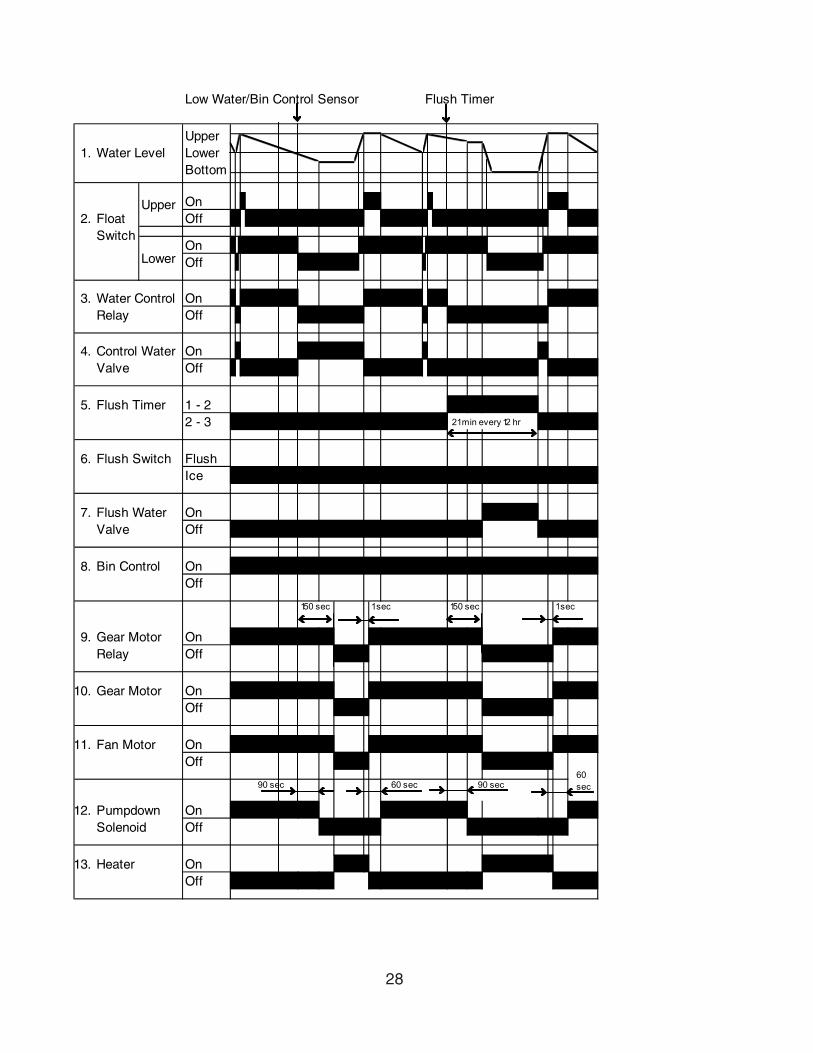
On2. Off
OnOff
3. OnOff
4. OnOff
5. 1 - 22 - 3 21 min every 12 hr
6. FlushIce
7. OnOff
8. Bin Control OnOff
150 sec 1 sec 150 sec 1 sec
9. OnOff
10. OnOff
11. OnOff
60 sec 90 sec
12. OnOff
13. Heater OnOff
1.
Water Control Relay
Lower
Water Level
Float Switch
UpperLowerBottom
Gear Motor
Fan Motor
Control Water Valve
Upper
Pumpdown Solenoid
Gear Motor Relay
Low Water/Bin Control Sensor Flush Timer
Flush Water Valve
Flush Timer
Flush Switch
60 sec 90 sec

29
On2. Off
OnOff
3. OnOff
4. OnOff
5. 1 - 22 - 3
6. FlushIce
7. OnOff
8. Bin Control OnOff
150 sec 1 sec
9. OnOff
10. OnOff
11. OnOff
60 sec
12. OnOff
13. Heater OnOff
1.
Water Control Relay
1 sec
Control Water Valve
Upper
Lower
Water Level
Float Switch
UpperLowerBottom
Pumpdown Solenoid
Gear Motor Relay
Flush Timer
Flush Switch
Pressure Switch
Flush Water Valve
Gear Motor
Fan Motor
On Off
1 sec
60 sec 90 sec
Flush Switch Flush Ice

30
E. Performance Data1. FS-1001MLH
We reserve the right to make changes in specifications and design without prior notice.
No Data Available

31
2. FS-1001MLH-C
We reserve the right to make changes in specifications and design without prior notice.
Performance Data:APPROXIMATE Ambient Water Temp. (F)ICE PRODUCTION Temp. (F)PER 24 HR. 70 *832 378 803 365 784 356
80 765 347 747 340 729 33190 712 324 *703 320 679 309
lbs./DAY ( l/day) 100 663 301 647 294 *600 273APPROXIMATE ELECTRIC 70 1713 -- 1717 -- 1722 --CONSUMPTION 80 1727 -- 1731 -- 1736 --
90 1740 -- 1745 -- 1760 --watts 100 1775 -- 1789 -- 1804 --APPROXIMATE WATER 70 *100 377 96 364 94 356CONSUMPTION PER 24 HR. 80 92 347 90 339 88 331
90 85 323 *84 319 81 308gal. / day (l/day) 100 80 301 78 293 *72 272EVAPORATOR OUTLET TEMP. 70 *14 -10 14 -10 14 -10F ( C) 80 14 -10 16 -9 16 -9
90 16 -9 *16 -9 18 -8100 18 -8 18 -8 *18 -8
HEAD PRESSURE 70 *224 15.7 224 15.7 224 15.780 233 16.4 233 16.4 233 16.490 242 17.0 *242 17.0 242 17.0
PSIG (kg/sq.cmG) 100 279 19.6 279 19.6 *279 19.6SUCTION PRESSURE 70 *29 2.0 29 2.0 29 2.0PSIG (kg/sq.cmG) 80 30 2.1 30 2.1 30 2.1
90 31 2.2 *31 2.2 31 2.2100 33 2.3 33 2.3 *33 2.3
Note: The data without *marks should be used for reference.
50 70 90
HEAT OF REJECTION FROM BODY 1130 BTU/hr AT 90 F/WT 70 F

32
IV. Service DiagnosisA. No Ice Production
1. Icemaker
Problem Possible Cause Remedy[1] The icemaker will not
start.a) Power Supply 1. OFF position. 1. Move to ON position.
2. Loose connection. 2. Tighten.
3. Bad contacts. 3. Check for continuity and replace.
4. Blown fuse. 4. Replace.
b) Power Switch 1. Off position. 1. Move to ON position.
(Control Box) 2. Bad contacts. 2. Check for continuity and replace.
c) Fuse (Control Box) 1. Blown out. 1. Check for short circuit and replace.
d) Circuit Protect Relay 1. Miswiring. 1. Check power supply voltage and wire properly.
e) Flush Timer 1. Flushing out. 1. Wait for 15 minutes.2. Bad contacts. 2. Check for continuity and
replace.
f) Flush Switch 1. FLUSH position. 1. Move to ICE position.
2. Bad contacts. 2. Check for continuity and replace.
g) Transformer 1. Coil winding opened. 1. Replace.
h) Control Water Valve 1. Coil winding opened. 1. Replace.
i) Shut-off Valve 1. Closed. 1. Open.
2. Water failure. 2. Wait until water is supplied.
j) Plug and Receptacle 1. Disconnected. 1. Connect.(Control Box) 2. Terminal out of plug or
receptacle.2. Insert terminal back in
position.
k) Bin Control Sensor 1. Failed sensor. 1. Check LED with power switch on. Replace if necessary.
2. Wet or scaled eye. 2. Wipe off and clean sensor eye.
[2] a) Water Control Relay 1. Contact fused. 1. Replace.
2. Coil winding opened. 2. Replace.
b) Float Switch 1. Bad contacts. 1. Check for continuity and replace.
2. Float does not move freely.
2. Clean or replace.
c) Flush Water Valve 1. Valve seat clogged and water leaking.
1. Clean or replace.
d) Hoses 1. Disconnected. 1. Connect.
Water does not stop, and the icemaker will not start.
33
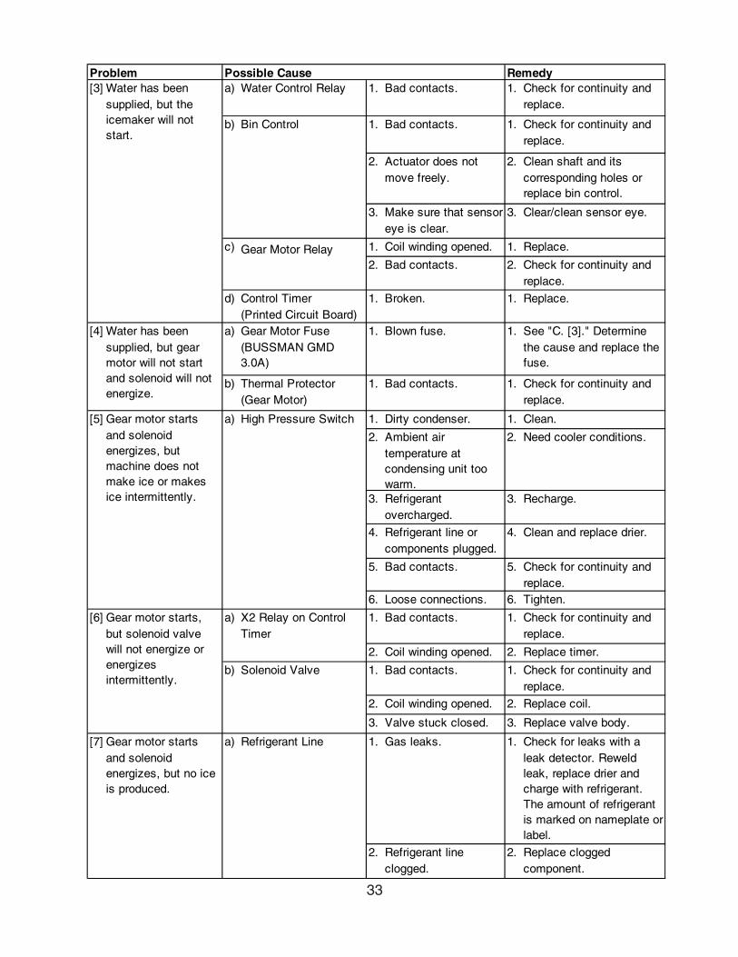
Problem Possible Cause Remedy[3] a) Water Control Relay 1. Bad contacts. 1. Check for continuity and
replace.
b) Bin Control 1. Bad contacts. 1. Check for continuity and replace.
2. Actuator does not move freely.
2. Clean shaft and its corresponding holes or replace bin control.
3. Make sure that sensor eye is clear.
3. Clear/clean sensor eye.
c) Gear Motor Relay 1. Coil winding opened. 1. Replace.
2. Bad contacts. 2. Check for continuity and replace.
d) Control Timer (Printed Circuit Board)
1. Broken. 1. Replace.
[4] a) Gear Motor Fuse (BUSSMAN GMD 3.0A)
1. Blown fuse. 1. See "C. [3]." Determine the cause and replace the fuse.
b) Thermal Protector (Gear Motor)
1. Bad contacts. 1. Check for continuity and replace.
[5] a) High Pressure Switch 1. Dirty condenser. 1. Clean.
2. Ambient air temperature at condensing unit too warm.
2. Need cooler conditions.
3. Refrigerant overcharged.
3. Recharge.
4. Refrigerant line or components plugged.
4. Clean and replace drier.
5. Bad contacts. 5. Check for continuity and replace.
6. Loose connections. 6. Tighten.
[6] a) 1. Bad contacts. 1. Check for continuity and replace.
2. Coil winding opened. 2. Replace timer.
b) Solenoid Valve 1. Bad contacts. 1. Check for continuity and replace.
2. Coil winding opened. 2. Replace coil.
3. Valve stuck closed. 3. Replace valve body.
[7] Gear motor starts and solenoid energizes, but no ice is produced.
a) Refrigerant Line 1. Gas leaks. 1. Check for leaks with a leak detector. Reweld leak, replace drier and charge with refrigerant. The amount of refrigerant is marked on nameplate or label.
2. Refrigerant line clogged.
2. Replace clogged component.
Water has been supplied, but the icemaker will not start.
X2 Relay on Control Timer
Water has been supplied, but gear motor will not start and solenoid will not energize.
Gear motor starts, but solenoid valve will not energize or energizes intermittently.
Gear motor starts and solenoid energizes, but machine does not make ice or makes ice intermittently.
34
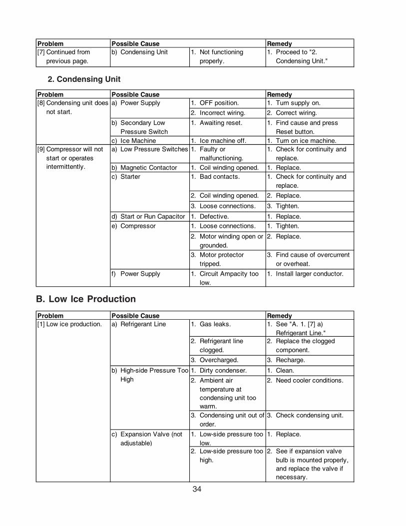
B. Low Ice Production
2. Condensing Unit
Problem Possible Cause Remedy[8] a) 1. OFF position. 1. Turn supply on.
2. Incorrect wiring. 2. Correct wiring.
b) Secondary Low Pressure Switch
1. Awaiting reset. 1. Find cause and press Reset button.
c) Ice Machine 1. Ice machine off. 1. Turn on ice machine.[9] a) Low Pressure Switches 1. Faulty or
malfunctioning.1. Check for continuity and
replace.
b) Magnetic Contactor 1. Coil winding opened. 1. Replace.c) Starter 1. Bad contacts. 1. Check for continuity and
replace.
2. Coil winding opened. 2. Replace.
3. Loose connections. 3. Tighten.
d) Start or Run Capacitor 1. Defective. 1. Replace.
e) Compressor 1. Loose connections. 1. Tighten.
2. Motor winding open or grounded.
2. Replace.
3. Motor protector tripped.
3. Find cause of overcurrent or overheat.
f) Power Supply 1. Circuit Ampacity too low.
1. Install larger conductor.
Power SupplyCondensing unit does not start.
Compressor will not start or operates intermittently.
Problem Possible Cause Remedy[7] Continued from
previous page.b) Condensing Unit 1. Not functioning
properly.1. Proceed to "2.
Condensing Unit."
Problem Possible Cause Remedy[1] Low ice production. a) Refrigerant Line 1. Gas leaks. 1. See "A. 1. [7] a)
Refrigerant Line."2. Refrigerant line
clogged.2. Replace the clogged
component.
3. Overcharged. 3. Recharge.
b) 1. Dirty condenser. 1. Clean.
2. Ambient air temperature at condensing unit too warm.
2. Need cooler conditions.
3. Condensing unit out of order.
3. Check condensing unit.
c) Expansion Valve (not adjustable)
1. Low-side pressure too low.
1. Replace.
2. Low-side pressure too high.
2. See if expansion valve bulb is mounted properly, and replace the valve if necessary.
High-side Pressure Too High
35
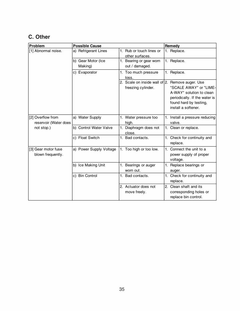
C. Other
Problem Possible Cause Remedy[1] Abnormal noise. a) Refrigerant Lines 1. Rub or touch lines or
other surfaces.1. Replace.
b) Gear Motor (Ice Making)
1. Bearing or gear worn out / damaged.
1. Replace.
c) Evaporator 1. Too much pressure loss.
1. Replace.
2. Scale on inside wall of freezing cylinder.
2. Remove auger. Use "SCALE AWAY" or "LIME-A-WAY" solution to clean periodically. If the water is found hard by testing, install a softener.
[2] a) Water Supply 1. Water pressure too high.
1. Install a pressure reducing valve.
b) Control Water Valve 1. Diaphragm does not close.
1. Clean or replace.
c) Float Switch 1. Bad contacts. 1. Check for continuity and replace.
[3] Gear motor fuse blown frequently.
a) Power Supply Voltage 1. Too high or too low. 1. Connect the unit to a power supply of proper voltage.
b) Ice Making Unit 1. Bearings or auger worn out.
1. Replace bearings or auger.
c) Bin Control 1. Bad contacts. 1. Check for continuity and replace.
2. Actuator does not move freely.
2. Clean shaft and its corresponding holes or replace bin control.
Overflow from reservoir (Water does not stop.)

36
V. Removal and Replacement of Components
IMPORTANTEnsure all components, fasteners and thumbscrews are securely in placeafter the equipment is serviced.
IMPORTANT1. The Polyolester (POE) oils used in R-404A units can absorb moisture
quickly. Therefore it is important to prevent moisture from entering thesystem when replacing or servicing parts.
2. Always install a new filter drier every time the sealed refrigeration systemis opened.
3. Do not leave the system open for longer than 15 minutes when replacingor servicing parts.
A. Service for Refrigerant Lines
1. Refrigerant RecoveryThe icemaker unit is provided with two refrigerant service valves - one on the low-sideand one on the high-side line. Using proper refrigerant practices recover the refrigerantfrom the service valves and store it in an approved container. Do not discharge therefrigerant into the atmosphere.
2. Evacuation and Recharge [R-404A]a) CompleteFor complete evacuation of ice machine and condensing unit, follow the stepsbelow.
Note: For replacement of components inside the ice machine, a complete evacuationis not necessary. For partial evacuation with pumpdown, see “Partialevacuation with pumpdown” below.
1) Attach charging hoses, a service manifold and a vacuum pump to the system. Besure to connect charging hoses to both high-side and low-side service valves.
WARNINGService valves have no valve core. Be sure valve stems are closed beforeremoving the flare caps to attach charging hoses.
IMPORTANTThe vacuum level and vacuum pump may be the same as those for currentrefrigerants. However, the rubber hose and gauge manifold to be used forevacuation and refrigerant charge should be exclusively for POE oils.

37
2) Turn on the vacuum pump. Never allow the oil in the vacuum pump to flow backwards.
3) Allow the vacuum pump to pull down to a 29.9" Hg vacuum. Evacuating period dependson pump capacity.
4) Close the low-side valve and high-side valve on the service manifold.
5) Disconnect the vacuum pump and attach a refrigerant service cylinder to the high-sideline. Remember to loosen the connection and purge the air from the hose. See the ratinglabel on the control box in the icemaker for the required refrigerant charge. Hoshizakirecommends only virgin refrigerant or reclaimed refrigerant which meets ARI StandardNo. 700-88 be used.
6) A liquid charge is recommended for charging an R-404A system. Invert the servicecylinder if necessary. Open the high-side, service manifold valve.
7) Allow the system to charge with liquid until the pressures balance.
8) If necessary, add any remaining charge to the system through the low-side. Use athrottling valve or liquid dispensing device to add the remaining liquid chargethrough thelow-side access port with the unit running.
9) Close the two refrigerant service valves and disconnect the hoses and servicemanifold.
WARNINGService valves have no valve core. Be sure valve stems are closed beforedisconnecting the hoses.
10) Cap the service valves to prevent a possible leak.
b) Partial evacuation with pumpdownFor replacement of components inside the ice machine, only a partial evacuation withpumpdown is necessary.
1) If not already running, turn on the ice machine, making sure that the solenoid valveenergizes and that the bin control is not activated.
2) Turn off the power supply to the condensing unit.
3) In the condensing unit, close the liquid line shut-off valve by rotating the valve stemclockwise until it is fully seated.
38
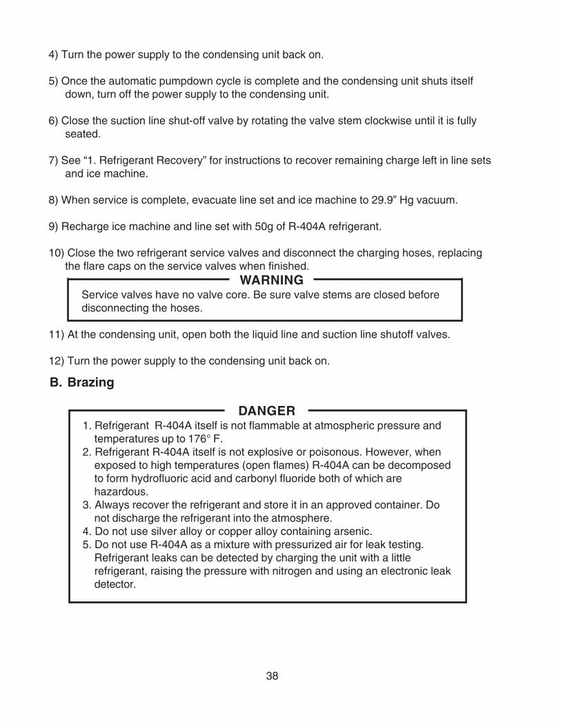
B. Brazing
DANGER1. Refrigerant R-404A itself is not flammable at atmospheric pressure and
temperatures up to 176° F.2. Refrigerant R-404A itself is not explosive or poisonous. However, when
exposed to high temperatures (open flames) R-404A can be decomposedto form hydrofluoric acid and carbonyl fluoride both of which arehazardous.
3. Always recover the refrigerant and store it in an approved container. Donot discharge the refrigerant into the atmosphere.
4. Do not use silver alloy or copper alloy containing arsenic.5. Do not use R-404A as a mixture with pressurized air for leak testing.
Refrigerant leaks can be detected by charging the unit with a littlerefrigerant, raising the pressure with nitrogen and using an electronic leakdetector.
4) Turn the power supply to the condensing unit back on.
5) Once the automatic pumpdown cycle is complete and the condensing unit shuts itselfdown, turn off the power supply to the condensing unit.
6) Close the suction line shut-off valve by rotating the valve stem clockwise until it is fullyseated.
7) See “1. Refrigerant Recovery” for instructions to recover remaining charge left in line setsand ice machine.
8) When service is complete, evacuate line set and ice machine to 29.9” Hg vacuum.
9) Recharge ice machine and line set with 50g of R-404A refrigerant.
10) Close the two refrigerant service valves and disconnect the charging hoses, replacingthe flare caps on the service valves when finished.
WARNINGService valves have no valve core. Be sure valve stems are closed beforedisconnecting the hoses.
11) At the condensing unit, open both the liquid line and suction line shutoff valves.
12) Turn the power supply to the condensing unit back on.
39
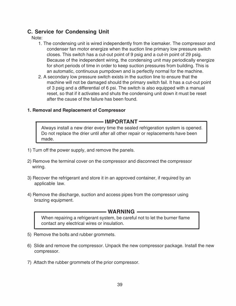
C. Service for Condensing UnitNote:
1. The condensing unit is wired independently from the icemaker. The compressor andcondenser fan motor energize when the suction line primary low pressure switchcloses. This switch has a cut-out point of 9 psig and a cut-in point of 29 psig.Because of the independent wiring, the condensing unit may periodically energizefor short periods of time in order to keep suction pressures from building. This isan automatic, continuous pumpdown and is perfectly normal for the machine.
2. A secondary low pressure switch exists in the suction line to ensure that themachine will not be damaged should the primary switch fail. It has a cut-out pointof 3 psig and a differential of 6 psi. The switch is also equipped with a manualreset, so that if it activates and shuts the condensing unit down it must be resetafter the cause of the failure has been found.
1. Removal and Replacement of Compressor
IMPORTANTAlways install a new drier every time the sealed refrigeration system is opened.Do not replace the drier until after all other repair or replacements have beenmade.
1) Turn off the power supply, and remove the panels.
2) Remove the terminal cover on the compressor and disconnect the compressor wiring.
3) Recover the refrigerant and store it in an approved container, if required by anapplicable law.
4) Remove the discharge, suction and access pipes from the compressor usingbrazing equipment.
WARNINGWhen repairing a refrigerant system, be careful not to let the burner flamecontact any electrical wires or insulation.
5) Remove the bolts and rubber grommets.
6) Slide and remove the compressor. Unpack the new compressor package. Install the newcompressor.
7) Attach the rubber grommets of the prior compressor.

40
8) Sandpaper the discharge, suction and access pipes.
9) Place the compressor in position and secure it using the bolts.
10) Remove plugs from the discharge, suction and access pipes.
11) Braze the access, suction and discharge lines (Do not change this order),while purging with nitrogen gas flowing at a pressure of 3 - 4 psig.
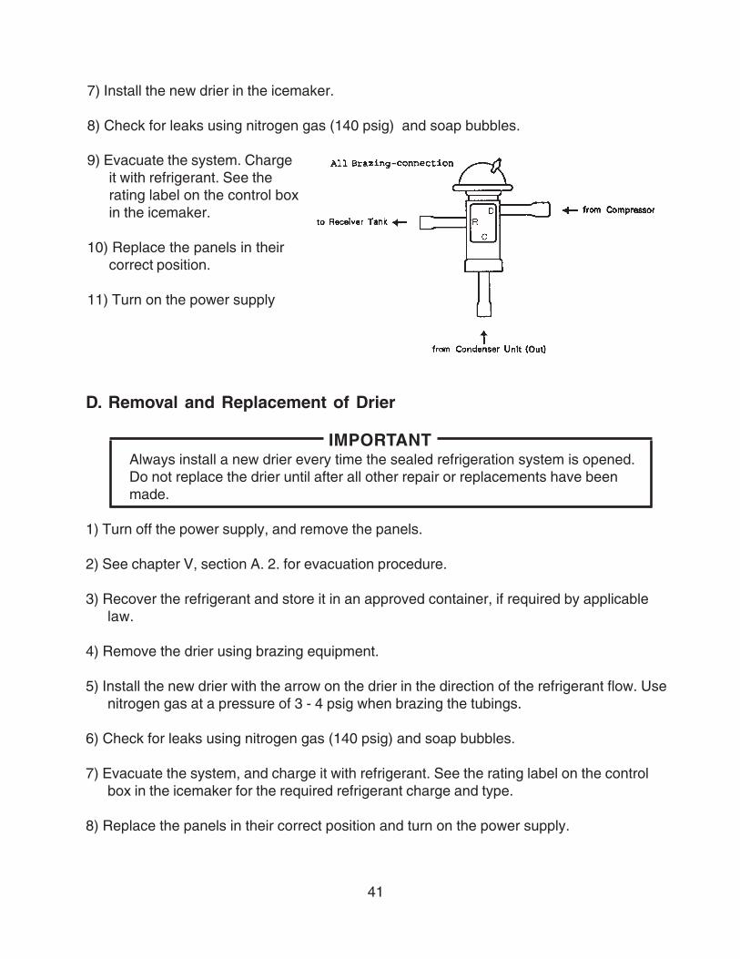
12) Install the new drier in the icemaker.
13) Check for leaks using nitrogen gas (140 psig) and soap bubbles.
14) Evacuate the system, and charge it with refrigerant. See the rating label on the controlbox in the icemaker for the required refrigerant charge and type.
15) Connect the terminals to the compressor, and replace the terminal cover in its correctposition.
16) Replace the panels in their correct positions, and turn on the power supply.
2. Removal and Replacement of Condensing Pressure Regulator (C.P.R.)
IMPORTANTAlways install a new drier every time the sealed refrigeration system is opened.Do not replace the drier until after all other repairs or replacements have beenmade.
1) Turn off the power supply to the condensing unit.
2) Remove the panels from the condensing unit.
3) See chapter V, section A. 2. a) and perform the complete evacuation procedure.
4) Recover the refrigerant and store it in an approved container.
5) Remove the C.P.R. using brazing equipment.
6) Braze the new C.P.R. with nitrogen gas flowing at a pressure of 3 - 4 psig.
WARNINGAlways protect the C.P.R. body by using a damp cloth to prevent the C.P.R.from overheating. Do not braze with the C.P.R. body exceeding 250°F.
41
D. Removal and Replacement of Drier
IMPORTANTAlways install a new drier every time the sealed refrigeration system is opened.Do not replace the drier until after all other repair or replacements have beenmade.
1) Turn off the power supply, and remove the panels.
2) See chapter V, section A. 2. for evacuation procedure.
3) Recover the refrigerant and store it in an approved container, if required by applicablelaw.
4) Remove the drier using brazing equipment.
5) Install the new drier with the arrow on the drier in the direction of the refrigerant flow. Usenitrogen gas at a pressure of 3 - 4 psig when brazing the tubings.
6) Check for leaks using nitrogen gas (140 psig) and soap bubbles.
7) Evacuate the system, and charge it with refrigerant. See the rating label on the controlbox in the icemaker for the required refrigerant charge and type.
8) Replace the panels in their correct position and turn on the power supply.
7) Install the new drier in the icemaker.
8) Check for leaks using nitrogen gas (140 psig) and soap bubbles.
9) Evacuate the system. Chargeit with refrigerant. See therating label on the control boxin the icemaker.
10) Replace the panels in theircorrect position.
11) Turn on the power supply

42
E. Removal and Replacement of Expansion Valve
IMPORTANTSometimes moisture in the refrigerant circuit exceeds the drier capacity andfreezes up at the expansion valve. Always install a new drier every time thesealed refrigeration system is opened. Do not replace the drier until after allother repairs or replacements have been made.
1) Turn off the power supply, and remove the panels.
2) See chapter V, section A. 2. for evacuation procedure.
3) Recover the refrigerant and store it in an approved container, if required by applicablelaw.
4) Remove the expansion valve bulb at the evaporator outlet.
5) Remove the expansion valve cover and remove the expansion valve using brazingequipment.
6) Braze the new expansion valve with nitrogen gas flowing at a pressure of 3 - 4 psig.
WARNINGAlways protect the valve body by using a damp cloth to prevent the valve fromoverheating. Do not braze with the valve body exceeding 250°F.
7) Install the new drier.
8) Check for leaks using nitrogen gas (140 psig) and soap bubbles.
9) Evacuate the system. Charge it with refrigerant. See the rating label on the control box inthe icemaker for the required refrigerant charge and type.
10) Attach the bulb to the suction line and make it level. Be sure to secure the bulb using a band and to insulate it.
11) Place the new set of expansion valve covers in position.
12) Replace the panels in their correct position and turn on the power supply.
43
F. Removal and Replacement of Evaporator Assembly
1) Turn off the power supply.
2) Remove the panels.
3) Move the flush switch to the “FLUSH” position.
4) Turn on the power supply and drain out all water from the water line.
5) Turn off the power supply.
6) Remove the strap connecting the spout to the chute assembly.
7) Remove the three thumbscrews and take off the spout from the evaporator.
Cutter
8) Remove the bolt and lift off the cutter.
9) Remove the rubber O-ring and the nylon ring at the top of the evaporator.
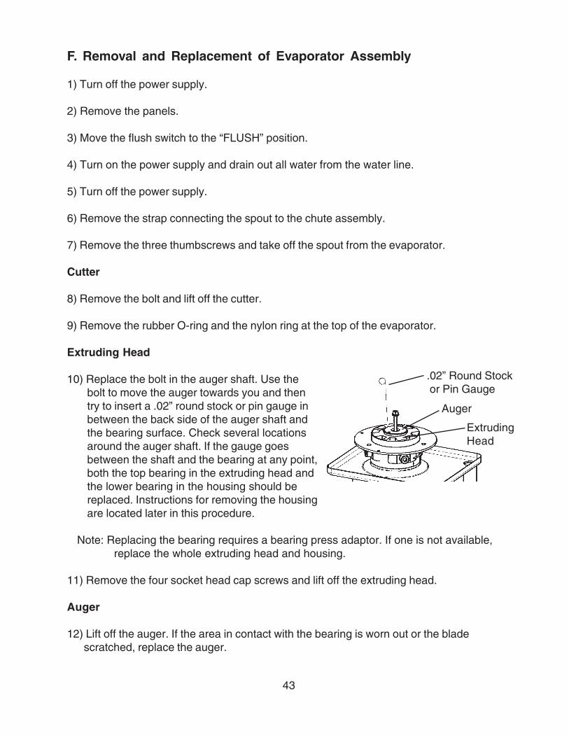
Extruding Head
10) Replace the bolt in the auger shaft. Use thebolt to move the auger towards you and thentry to insert a .02” round stock or pin gauge inbetween the back side of the auger shaft andthe bearing surface. Check several locationsaround the auger shaft. If the gauge goesbetween the shaft and the bearing at any point,both the top bearing in the extruding head andthe lower bearing in the housing should bereplaced. Instructions for removing the housingare located later in this procedure.
Note: Replacing the bearing requires a bearing press adaptor. If one is not available,replace the whole extruding head and housing.
11) Remove the four socket head cap screws and lift off the extruding head.
Auger
12) Lift off the auger. If the area in contact with the bearing is worn out or the bladescratched, replace the auger.
.02” Round Stock or Pin Gauge
ExtrudingHead
Auger

44
Evaporator
Note: Skip the following steps 13) through 15) when the evaporator does not needreplacement.
13) See chapter V, section A. 2. b) and perform the partial evacuation procedure.
14) Recover the refrigerant and store it in an approved container, if required by an applicable law.
IMPORTANTAlways install a new drier every time the sealed refrigeration system is opened.Do not replace the drier until after all other repair or replacements have beenmade.
15) Remove the bulb of the expansion valve.
16) Disconnect the brazing-connections of the expansion valve and the copper tube-lowside from the evaporator, using brazing equipment.
17) Remove the two truss head machine screws and the strap securing the evaporator.
18) Disconnect the two hoses from the evaporator.
19) Remove the four socket head cap screws securing the evaporator to the housing.
20) Lift off the evaporator.
Housing, Lower Bearing and Mechanical Seal
21) The mechanical seal consists of two parts. One moves along with the auger, and the other is fixed on the housing. If the contact surfaces of these two parts are worn or scratched, the mechanical seal may cause water leaks and should be replaced.
22) Remove the O-ring from the housing.
23) Remove the six bolts and the housing from the gear motor. If inspection of the bearinginside the extruding head (earlier in this procedure) indicated that it is out of tolerance,replace both it and the bearing inside the housing.
Note: Replacing the bearing requires a bearing press adaptor. If one is not available,replace the whole extruding head and housing.

45
Gear Motor
24) Remove the coupling-spline on the gear motor shaft.
25) Remove the barrier on the top of the gear motor.
26) Remove the three socket head cap screws securing the gear motor.
27) Assemble the removed parts in the reverse order of the above procedure.
WARNINGBe careful not to scratch the surface of the O-ring or it may cause water leaks.Handle the mechanical seal with care not to scratch or contaminate its contactsurface.
28) When replacing the evaporator;
(a) Braze the new evaporator with nitrogen gas flowing at a pressure of 3 - 4 psig. Be carefulnot to burn the evaporator insulation.
(b) Replace the drier.
(c) Check for leaks using nitrogen gas (140 psig) and soap bubbles.
(d) Evacuate the system. Charge it with refrigerant.
29) Move the flush switch to the “ICE” position.
30) Replace the panels in their correct position.
31) Turn on the power supply.

46
Rubber O-ring
Nylon Ring
BoltDowel PinCutter
Extruding Head
Evaporator
Socket HeadCap Screw
Auger
Mechanical Seal
O-ring
Housing
Gear Motor
Coupling - Spline
Heater with Spring
Socket HeadCap Screw
Hex Head Bolt
Spring Washer
Washer
Barrier - Gear Motor
Truss HeadScrew
Split Lock Washer
Washer
Washer
47
G. Removal and Replacement of Control Water Valve
1) Turn off the power supply, remove the panels and close the water supply line shut-offvalve.
2) Disconnect the terminals from the control water valve.
3) Loosen the fitting nut on the control water valve inlets and remove the control water valve.Do not lose the packings inside the fitting nut.
4) Remove the water supply hose from the control water valve.
5) Install the new control water valve.
6) Assemble the removed parts in the reverse order of the above procedure.
7) Open the water supply line shut-off valve.
8) Check for water leaks.
9) Replace the panels in their correct position, then turn on the power supply.

48
H. Removal and Replacement of Flush Water Valve
1) Turn off the power supply, remove the panels and close the water supply line shut-offvalve.
2) Remove the clamp and disconnect the flush water valve.
Note: Water may still remain inside the evaporator. Be sure to drain the water into thedrain pan.
3) Disconnect the terminals from the flush water valve.
4) Remove the flush water valve from the bracket.
5) Remove the drain pipe from the flush water valve.
6) Connect the drain pipe to the new flush water valve and place the valve in position.
7) Connect the hose to the flush water valve and secure it with the clamp.
8) Pour water into the reservoir and check for water leaks on the flush water valve.
9) Open the water supply line shut-off valve, then turn on the power supply.
10) Move the flush switch to the “ICE” position.
11) Check for water leaks.
12) Move the flush switch to the “FLUSH” position and make sure water is flushing.
13) Move the flush switch to the “ICE” position.
14) Replace the panels in their correct position.

49
VI. Cleaning and Maintenance
IMPORTANTEnsure all components, fasteners and thumbscrews are securely in place afterany maintenance or cleaning is done to the equipment.
A. Preparing the Icemaker for Long Storage
WARNINGWhen shutting off the icemaker for an extended time, drain out all water from thewater line and remove the ice from the storage bin. The storage bin should becleaned and dried. Drain the icemaker to prevent damage to the water supplyline at sub-freezing temperatures, using air or carbon dioxide. Shut off theicemaker until the proper ambient temperature is resumed.
1) Run the icemaker with the water supply line shut-off valve closed.
2) Open the drain valve and blow out the water inlet line by using air pressure.
3) Turn off the power supply.
4) Remove the front panel.
5) Move the flush switch on the control box to the “FLUSH” position.
6) Turn on the power supply, and then drain out all water from the water line.
7) Turn off the power supply.
8) Turn off the power switch on the control box.
9) Replace the front panel in its correct position.
10) Close the drain valve.
11) Remove all ice from the storage bin, and clean the bin.

50
B. Cleaning and Sanitizing Instructions
WARNING1. HOSHIZAKI recommends cleaning this unit at least once a year. More
frequent cleaning, however, may be required in some existing waterconditions.
2. To prevent injury to individuals and damage to the icemaker, do not useammonia type cleaners.
3. Always wear liquid-proof gloves to prevent the cleaning and sanitizingsolutions from coming into contact with skin.
1. Cleaning Solution
Dilute 4.8 fl. oz. (142 ml) of recommended cleaner Hoshizaki “Scale Away” or“LIME-A-WAY” (Economics Laboratory, Inc.) with 0.8 gallons (3 l) of warm water. This is aminimum amount. Make more solution if necessary.
IMPORTANTFor safety and maximum effectiveness, use the solution immediately afterdilution.
2. Cleaning Procedure
The cleaning process will remove lime deposits from the water system.
1) Remove the front panel and top panel, then turn off the power supply.
2) Close the water supply line shut-off valve.
3) Remove all ice from the storage bin.
4) Move the flush switch to the “FLUSH” position.
5) Turn on the power supply and drain out all water from the water line.
6) Turn off the power supply.
7) Remove the control water valve by removing the fitting nut and two mounting screws. Donot lose the packing.
8) Check the control water valve screen for debris and clean as necessary.
51
9) Replace the control water valve in its correct position.
10) Remove the strap connecting the spout to the chute assembly.
11) Remove the thumbscrews securing the spout and lift it off.
12) Pour the cleaning solution over the extruding head until the evaporator assembly andthe reservoir are filled and the solution starts to overflow into the drain pan.
Note: If there is excess scale on the extruding head, fill the evaporator assembly andreservoir as described above, then use a clamp on the reservoir hose between thereservoir and evaporator assembly to block flow. Pour additional cleaning fluidover the extruding head until the evaporator assembly is completely full.
13) Replace the spout and strap in their correct positions.
14) Allow the icemaker to sit for about 10 minutes before operation. If you placed a clamp onthe reservoir hose in step 9, remove it before operation.
15) Move the flush switch to the “ICE” position, then turn on the power supply. Replace thetop panel and front panel in their correct positions. Make ice using the solution until theicemaker stops making ice.
Note: Always discard the contaminated ice produced during this procedure.
16) Remove the front panel.
17) Move the flush switch to the “FLUSH” position to drain the remainder of the solution.
18) After the solution is drained, move the flush switch to the “ICE” position.
19) Replace the front panel in its correct position.
20) Open the water supply line shut-off valve and supply water to the reservoir.
21) When the gear motor starts, remove the front panel and turn off the power supply.
22) Drain out all water from the water line. See 4) through 6).

52
3. Sanitizing Solution
Dilute 2.5 fl. oz. (74 ml or 5 tbs) of IMS-II Sanitizer or a 5.25% sodium hypochlorite solution(chlorine bleach) with 5 gallons (19 l) of warm water.
IMPORTANTFor safety and maximum effectiveness, use the solution immediately afterdilution.
4. Sanitizing Procedure - Initial
The sanitizing process will sanitize the icemaker.
1) Close the water supply line shut-off valve.
2) Remove the strap connecting the spout to the chute assembly.
3) Remove the thumbscrews securing the spout and lift it off. Remove the rubber O-ring andnylon O-ring at the top of the cylinder and also remove the packing between the spoutand the chute.
4) Pour the sanitizing solution over the extruding head until the evaporator assembly andthe reservoir are filled and the solution starts to overflow into the drain pan.
5) Remove the two thumbscrews securing the proximity switch to the chute assembly.
6) Remove the chute assembly from the icemaker.
7) Remove the packing at the bottom of the ice chute.
8) Remove the three ties and the chute insulation.
9) Remove the six wing nuts and two baffles.
10) Remove the two thumbscrews, the plate and the packing from the top of the ice chute,then remove the bin control assembly by sliding it slightly toward the chute opening andlifting it off.
11) Disassemble the bin control assembly by removing the two snap pins, shaft andactuator.
12) Soak the removed parts in .25 gallons (1 l) of sanitizing solution for 10 minutes thenwipe them down.
13) Rinse the parts thoroughly.IMPORTANT
If the solution is left on these parts, they will rust.
53
14) Replace all parts in their correct positions.
IMPORTANTWhen installing the baffles, make sure that the bent surface (the one without thestuds) faces the actuator so that the bent surface can guide the ice to the centerof the actuator.
15) Move the flush switch to the “ICE” position, then turn on the power supply. Replace thetop panel and front panel in their correct positions. Make ice using the solution until theicemaker stops making ice.
Note: Always discard the contaminated ice produced during this procedure.
5. Sanitizing Procedure - Final
1) Remove the front panel and top panel, then turn off the power supply.
2) Move the flush switch to the “FLUSH” position.
3) Turn on the power supply and drain out all water from the water line.
4) Turn off the power supply.
5) Remove the strap connecting the spout to the chute assembly.
6) Remove the thumbscrews securing the spout and lift it off.
7) Pour the sanitizing solution over the extruding head until the evaporator assembly andthe reservoir are filled and the solution starts to overflow into the drain pan.
8) Replace the spout and strap in their correct positions.
9) Allow the icemaker to sit for about 10 minutes before operation.
10) Move the flush switch to the “ICE” position, then turn on the power supply. Replace thetop panel and front panel in their correct positions. Make ice using the solution until theicemaker stops making ice.
Note: Always discard the contaminated ice produced during this procedure.
11) Remove the front panel.
12) Move the flush switch to the “FLUSH” position to drain the remainder of the solution.
13) After the solution is drained, move the flush switch to the “ICE” position.
14) Replace the front panel in its correct position.
15) Open the water supply line shut-off valve and supply water to the reservoir.

54
16) When the gear motor starts, remove the front panel and turn off the power supply.
17) Drain out all water from the water line. See 2) and 3).
18) Move the flush switch to the “ICE” position and run the icemaker.
19) Turn off the power supply after 30 minutes.
20) Pour warm water into the storage bin to melt all ice, and then clean the bin liner with thesolution.
21) Flush out any solution from the storage bin.
22) Turn on the power supply and start the automatic icemaking process.
IMPORTANT1. After cleaning, do not use ice made from the sanitizing solution. Be careful
not to leave any solution in the storage bin.2. Follow carefully any instructions provided with the bottles of cleaning or
sanitizing solution.3. Never run the icemaker when the reservoir is empty.

55
C. Maintenance Instructions
IMPORTANT1. This icemaker must be maintained individually, referring to the instruction
manual and labels provided with the icemaker.2. To achieve optimum icemaker performance, the following parts need periodic
inspection and maintenance:Extruding Head and Upper BearingHousing and Lower BearingEvaporator CylinderAugerGear MotorMechanical Seal
These parts should be inspected at least once a year or every 10,000hours of operation. Their service life, however, depends on water qualityand environment. More frequent inspection and maintenance arerecommended in bad or severe water conditions.Replacement of the following consumable parts is recommended if wearexceeds factory recommendations:
Upper BearingLower BearingMechanical Seal
Consult with your local distributor about inspection and maintenance service.To obtain the name and phone number of your local distributor, callHoshizaki Technical Support at 1-800-233-1940 in the USA.
1) Stainless Steel Exterior
To prevent corrosion, wipe the exterior occasionally with a clean and soft cloth. Use adamp cloth containing a neutral cleaner to wipe off oil or dirt build up.
2) Storage Bin and Scoop
• Wash your hands before removing ice. Use the plastic scoop provided (bin accessory).
• The storage bin is for ice use only. Do not store anything else in the bin.
• Keep the scoop clean. Clean using a neutral cleaner and rinse thoroughly.
• Clean the bin liner using a neutral cleaner. Rinse thoroughly after cleaning.
3) Condenser
Check the condenser once a year, and clean the coil if required by using a brush orvacuum cleaner. More frequent cleaning may be required depending on the locationof the condensing unit.