Service Manual - МедСенсор ... · SERVICE MANUAL ii 2011-08-15 ... DICOM Printer Status...
206
Confidential {ServiceManual}{Production}{Confidential} Publication No. 9G9002 2011-08-15 Service Manual
Transcript of Service Manual - МедСенсор ... · SERVICE MANUAL ii 2011-08-15 ... DICOM Printer Status...

Confidential
{ServiceManual}{Production}{Confidential}
Publication No. 9G90022011-08-15
Service Manual

SERVICE MANUAL
ii 2011-08-15 – 9G9002
KONICA MINOLTA DRYPRO SIGMA Laser Imaging System
Document No.: 9G9002
All rights reserved. No part of this manual may be reproduced or copied in any form by any means-graphic, electronic or mechanical, including photocopying, typing, or information retrieval systems-without written permission.
Important• Qualified service personnel must install and repair this equipment.
• When performing the procedures in this document, you must use safe work practices and wear the correct personal protective equipment (for example, safety eyewear) according to your company’s standard operating procedures.

2011-08-15 – 9G9002 iii
Description Page
Table of Contents
1. Installation Instructions . . . . . . . . . . . . . . . . . . . . . . . . . . . . . . . . . . . . . . . . . . . . . . . 1-1Necessary Materials . . . . . . . . . . . . . . . . . . . . . . . . . . . . . . . . . . . . . . . . . . . . . . . . . . 1-1Completing the Mechanical Setup . . . . . . . . . . . . . . . . . . . . . . . . . . . . . . . . . . . . . . . 1-2Configuring the Laser Imager . . . . . . . . . . . . . . . . . . . . . . . . . . . . . . . . . . . . . . . . . . . 1-9Completing the Installation . . . . . . . . . . . . . . . . . . . . . . . . . . . . . . . . . . . . . . . . . . . . . 1-13Troubleshooting . . . . . . . . . . . . . . . . . . . . . . . . . . . . . . . . . . . . . . . . . . . . . . . . . . . . . 1-15
2. Adjustments and Replacements . . . . . . . . . . . . . . . . . . . . . . . . . . . . . . . . . . . . . . . . 2-1Processor—Drum Temperature Adjustment . . . . . . . . . . . . . . . . . . . . . . . . . . . . . . . 2-1Imaging Assembly—Start Index Delay Adjustment . . . . . . . . . . . . . . . . . . . . . . . . . . 2-5Imaging Assembly—Page Start Adjustment. . . . . . . . . . . . . . . . . . . . . . . . . . . . . . . . 2-7Top Cover . . . . . . . . . . . . . . . . . . . . . . . . . . . . . . . . . . . . . . . . . . . . . . . . . . . . . . . . . . 2-9Left cover . . . . . . . . . . . . . . . . . . . . . . . . . . . . . . . . . . . . . . . . . . . . . . . . . . . . . . . . . . 2-10Right Cover. . . . . . . . . . . . . . . . . . . . . . . . . . . . . . . . . . . . . . . . . . . . . . . . . . . . . . . . . 2-11Back cover . . . . . . . . . . . . . . . . . . . . . . . . . . . . . . . . . . . . . . . . . . . . . . . . . . . . . . . . . 2-12Display Screen Assembly . . . . . . . . . . . . . . . . . . . . . . . . . . . . . . . . . . . . . . . . . . . . . . 2-13Interlock Switches—Top and Front Covers and Film Supply . . . . . . . . . . . . . . . . . . . 2-14Processor Drum . . . . . . . . . . . . . . . . . . . . . . . . . . . . . . . . . . . . . . . . . . . . . . . . . . . . . 2-15Drum Drive Belt . . . . . . . . . . . . . . . . . . . . . . . . . . . . . . . . . . . . . . . . . . . . . . . . . . . . . 2-17Processor Fan Assembly . . . . . . . . . . . . . . . . . . . . . . . . . . . . . . . . . . . . . . . . . . . . . . 2-19Felt Pad Assembly . . . . . . . . . . . . . . . . . . . . . . . . . . . . . . . . . . . . . . . . . . . . . . . . . . . 2-20Film Diverter Assembly. . . . . . . . . . . . . . . . . . . . . . . . . . . . . . . . . . . . . . . . . . . . . . . . 2-22Processor Cover . . . . . . . . . . . . . . . . . . . . . . . . . . . . . . . . . . . . . . . . . . . . . . . . . . . . . 2-23Densitometer Assembly . . . . . . . . . . . . . . . . . . . . . . . . . . . . . . . . . . . . . . . . . . . . . . . 2-24Feed Roller Motor . . . . . . . . . . . . . . . . . . . . . . . . . . . . . . . . . . . . . . . . . . . . . . . . . . . . 2-26Feed Roller Nip Drive Belt . . . . . . . . . . . . . . . . . . . . . . . . . . . . . . . . . . . . . . . . . . . . . 2-28Rollback Motor . . . . . . . . . . . . . . . . . . . . . . . . . . . . . . . . . . . . . . . . . . . . . . . . . . . . . . 2-29Film Cartridge Detect Sensor . . . . . . . . . . . . . . . . . . . . . . . . . . . . . . . . . . . . . . . . . . . 2-30Vacuum Pump . . . . . . . . . . . . . . . . . . . . . . . . . . . . . . . . . . . . . . . . . . . . . . . . . . . . . . 2-32Pickup Assembly . . . . . . . . . . . . . . . . . . . . . . . . . . . . . . . . . . . . . . . . . . . . . . . . . . . . 2-33Suction Cup . . . . . . . . . . . . . . . . . . . . . . . . . . . . . . . . . . . . . . . . . . . . . . . . . . . . . . . . 2-35Pickup Home Sensor . . . . . . . . . . . . . . . . . . . . . . . . . . . . . . . . . . . . . . . . . . . . . . . . . 2-36Film Contact Sensor . . . . . . . . . . . . . . . . . . . . . . . . . . . . . . . . . . . . . . . . . . . . . . . . . . 2-37Imaging Assembly . . . . . . . . . . . . . . . . . . . . . . . . . . . . . . . . . . . . . . . . . . . . . . . . . . . 2-38Optics and Exposure Transport . . . . . . . . . . . . . . . . . . . . . . . . . . . . . . . . . . . . . . . . . 2-40Exposure Transport Belt . . . . . . . . . . . . . . . . . . . . . . . . . . . . . . . . . . . . . . . . . . . . . . . 2-41Exposure Transport Motor . . . . . . . . . . . . . . . . . . . . . . . . . . . . . . . . . . . . . . . . . . . . . 2-42Power Supply Board . . . . . . . . . . . . . . . . . . . . . . . . . . . . . . . . . . . . . . . . . . . . . . . . . . 2-43Machine Control System (MCS) Board. . . . . . . . . . . . . . . . . . . . . . . . . . . . . . . . . . . . 2-44DRE Motherboard Bracket . . . . . . . . . . . . . . . . . . . . . . . . . . . . . . . . . . . . . . . . . . . . . 2-45DRE Motherboard and Flash Drive. . . . . . . . . . . . . . . . . . . . . . . . . . . . . . . . . . . . . . . 2-47
3. Preventive Maintenance . . . . . . . . . . . . . . . . . . . . . . . . . . . . . . . . . . . . . . . . . . . . . . . 3-1Necessary Materials . . . . . . . . . . . . . . . . . . . . . . . . . . . . . . . . . . . . . . . . . . . . . . . . . . 3-1PM Intervals . . . . . . . . . . . . . . . . . . . . . . . . . . . . . . . . . . . . . . . . . . . . . . . . . . . . . . . . 3-1Modifications. . . . . . . . . . . . . . . . . . . . . . . . . . . . . . . . . . . . . . . . . . . . . . . . . . . . . . . . 3-2EM Call Checklist . . . . . . . . . . . . . . . . . . . . . . . . . . . . . . . . . . . . . . . . . . . . . . . . . . . . 3-2Performing the PM . . . . . . . . . . . . . . . . . . . . . . . . . . . . . . . . . . . . . . . . . . . . . . . . . . . 3-4Resetting the PM Counts and Changing the Service History . . . . . . . . . . . . . . . . . . . 3-8Completing the PM . . . . . . . . . . . . . . . . . . . . . . . . . . . . . . . . . . . . . . . . . . . . . . . . . . . 3-8
SERVICE MANUAL
iv 2011-08-15 – 9G9002
4. Diagnostics . . . . . . . . . . . . . . . . . . . . . . . . . . . . . . . . . . . . . . . . . . . . . . . . . . . . . . . . . 4-1Display Screen Symbols—Detailed Descriptions. . . . . . . . . . . . . . . . . . . . . . . . . . . . 4-3DICOM Printer Status Messages . . . . . . . . . . . . . . . . . . . . . . . . . . . . . . . . . . . . . . . . 4-4Machine Control System (MCS) Imager Status Messages . . . . . . . . . . . . . . . . . . . . 4-5Film Supply Status Messages . . . . . . . . . . . . . . . . . . . . . . . . . . . . . . . . . . . . . . . . . . 4-6Job Manager Status Messages . . . . . . . . . . . . . . . . . . . . . . . . . . . . . . . . . . . . . . . . . 4-7Condition Codes. . . . . . . . . . . . . . . . . . . . . . . . . . . . . . . . . . . . . . . . . . . . . . . . . . . . . 4-8Clearing Film Jams . . . . . . . . . . . . . . . . . . . . . . . . . . . . . . . . . . . . . . . . . . . . . . . . . . 4-76Functions of the MCS Board Test Points, Jumpers, and Switches . . . . . . . . . . . . . . 4-80Motors and Sensors . . . . . . . . . . . . . . . . . . . . . . . . . . . . . . . . . . . . . . . . . . . . . . . . . . 4-81Using the Logs . . . . . . . . . . . . . . . . . . . . . . . . . . . . . . . . . . . . . . . . . . . . . . . . . . . . . . 4-82Log Keying Functions. . . . . . . . . . . . . . . . . . . . . . . . . . . . . . . . . . . . . . . . . . . . . . . . . 4-84Contents of the Log . . . . . . . . . . . . . . . . . . . . . . . . . . . . . . . . . . . . . . . . . . . . . . . . . . 4-85
5. Illustrated Parts List . . . . . . . . . . . . . . . . . . . . . . . . . . . . . . . . . . . . . . . . . . . . . . . . . . 5-1Main Assembly. . . . . . . . . . . . . . . . . . . . . . . . . . . . . . . . . . . . . . . . . . . . . . . . . . . . . . 5-1Cables and Harnesses. . . . . . . . . . . . . . . . . . . . . . . . . . . . . . . . . . . . . . . . . . . . . . . . 5-6Covers . . . . . . . . . . . . . . . . . . . . . . . . . . . . . . . . . . . . . . . . . . . . . . . . . . . . . . . . . . . . 5-8Exposure Transport Assembly . . . . . . . . . . . . . . . . . . . . . . . . . . . . . . . . . . . . . . . . . . 5-10Transport Assembly . . . . . . . . . . . . . . . . . . . . . . . . . . . . . . . . . . . . . . . . . . . . . . . . . . 5-11Pickup Assembly . . . . . . . . . . . . . . . . . . . . . . . . . . . . . . . . . . . . . . . . . . . . . . . . . . . . 5-12Feed Roller Assembly . . . . . . . . . . . . . . . . . . . . . . . . . . . . . . . . . . . . . . . . . . . . . . . . 5-14Processor Drum Assembly. . . . . . . . . . . . . . . . . . . . . . . . . . . . . . . . . . . . . . . . . . . . . 5-15Imaging Assembly . . . . . . . . . . . . . . . . . . . . . . . . . . . . . . . . . . . . . . . . . . . . . . . . . . . 5-16Local Panel (Display Screen) Assembly . . . . . . . . . . . . . . . . . . . . . . . . . . . . . . . . . . 5-17Electronics Assembly . . . . . . . . . . . . . . . . . . . . . . . . . . . . . . . . . . . . . . . . . . . . . . . . . 5-18Rollback Assembly. . . . . . . . . . . . . . . . . . . . . . . . . . . . . . . . . . . . . . . . . . . . . . . . . . . 5-19
6. Additional Service Procedures . . . . . . . . . . . . . . . . . . . . . . . . . . . . . . . . . . . . . . . . . 6-1Accessing the Service Tool . . . . . . . . . . . . . . . . . . . . . . . . . . . . . . . . . . . . . . . . . . . . 6-1Configuring the Laser Imager. . . . . . . . . . . . . . . . . . . . . . . . . . . . . . . . . . . . . . . . . . . 6-2Backing Up and Restoring Configurations . . . . . . . . . . . . . . . . . . . . . . . . . . . . . . . . . 6-14Upgrading Software and Firmware . . . . . . . . . . . . . . . . . . . . . . . . . . . . . . . . . . . . . . 6-16
Publication History . . . . . . . . . . . . . . . . . . . . . . . . . . . . . . . . . . . . . . . . . . . . . . . . . . . . I

Installation Instructions
9G9002 – 2011-08-15 1-1
Section 1: Installation Instructions
Necessary Materials• Service laptop with MICROSOFT WINDOWS 98 operating system or higher, and MICROSOFT INTERNET
EXPLORER
• Secure Link Client Software version 2.8.1 or higher (SecureLink)
• Web Service Portal Software version 4.0 or higher (Web Portal)
• Crossover cable
• Side cutters or scissors
• Phillips screwdriver

SERVICE MANUAL
1-2 9G9002 – 2011-08-15
Completing the Mechanical Setup
Completing the Uncrating[1] Locate and remove the accessories box that contains the documentation, cables, filter, and other accessories.
[2] Remove the 2 foam assemblies.
[3] Remove the side covers from the crate.
[4] Remove the bag from the laser imager.
CautionThe laser imager weighs less than or equal to 54 kg (120 lb) as packaged.
[5] Using safe lifting techniques, lift the laser imager from the shipping pallet at the lift points shown and set it on a flat surface.
Accessories Box Foam Assemblies
Lift Point Front Lift Point Rear
Installation Instructions
9G9002 – 2011-08-15 1-3
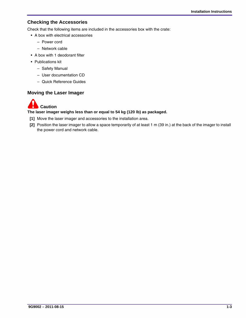
Checking the AccessoriesCheck that the following items are included in the accessories box with the crate:
• A box with electrical accessories
– Power cord
– Network cable
• A box with 1 deodorant filter
• Publications kit
– Safety Manual
– User documentation CD
– Quick Reference Guides
Moving the Laser Imager
CautionThe laser imager weighs less than or equal to 54 kg (120 lb) as packaged.
[1] Move the laser imager and accessories to the installation area.
[2] Position the laser imager to allow a space temporarily of at least 1 m (39 in.) at the back of the imager to install the power cord and network cable.
SERVICE MANUAL
1-4 9G9002 – 2011-08-15
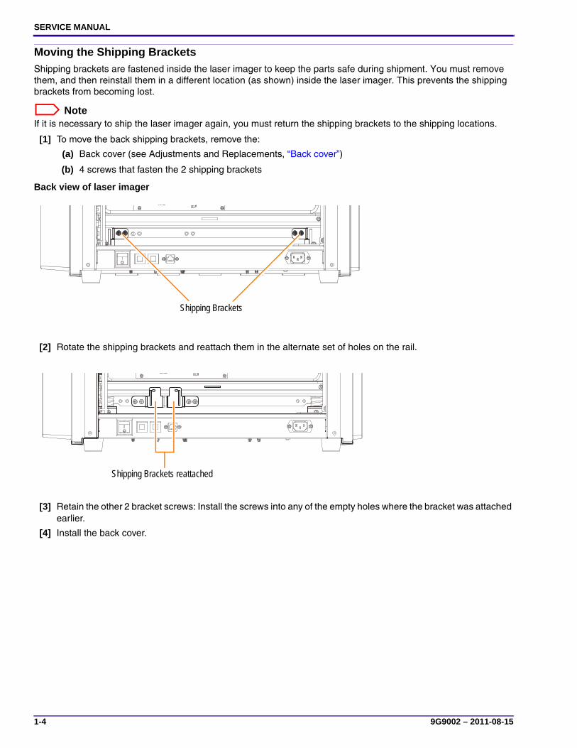
Moving the Shipping BracketsShipping brackets are fastened inside the laser imager to keep the parts safe during shipment. You must remove them, and then reinstall them in a different location (as shown) inside the laser imager. This prevents the shipping brackets from becoming lost.
NoteIf it is necessary to ship the laser imager again, you must return the shipping brackets to the shipping locations.
[1] To move the back shipping brackets, remove the:
(a) Back cover (see Adjustments and Replacements, “Back cover”)
(b) 4 screws that fasten the 2 shipping brackets
Back view of laser imager
[2] Rotate the shipping brackets and reattach them in the alternate set of holes on the rail.
[3] Retain the other 2 bracket screws: Install the screws into any of the empty holes where the bracket was attached earlier.
[4] Install the back cover.
Shipping Brackets
Shipping Brackets reattached
Installation Instructions
9G9002 – 2011-08-15 1-5
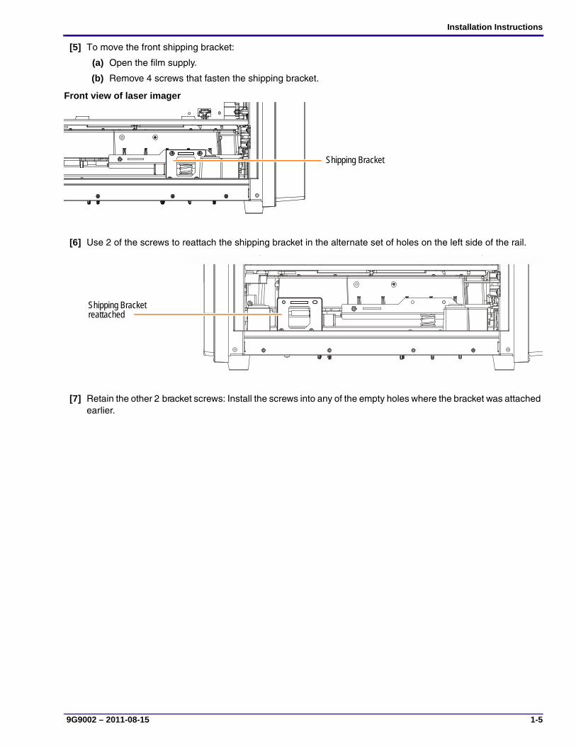
[5] To move the front shipping bracket:
(a) Open the film supply.
(b) Remove 4 screws that fasten the shipping bracket.
Front view of laser imager
[6] Use 2 of the screws to reattach the shipping bracket in the alternate set of holes on the left side of the rail.
[7] Retain the other 2 bracket screws: Install the screws into any of the empty holes where the bracket was attached earlier.
Front Shipping Bracket
(�lter removed)
Shipping Bracket
Front ShippingBracket inStorage
Shipping Bracket reattached
SERVICE MANUAL
1-6 9G9002 – 2011-08-15
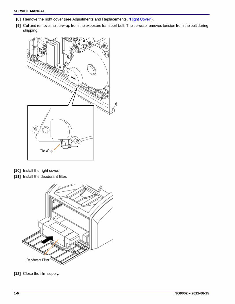
[8] Remove the right cover (see Adjustments and Replacements, “Right Cover”).
[9] Cut and remove the tie-wrap from the exposure transport belt. The tie wrap removes tension from the belt during shipping.
[10] Install the right cover.
[11] Install the deodorant filter.
[12] Close the film supply.
H221_6030GC
Tie Wrap
Deodorant Filter

Installation Instructions
9G9002 – 2011-08-15 1-7
Connecting to Electrical Power[1] Locate the power cord. The power cord must match the AC power outlets at your site.
If you cannot use the power cord that is provided, obtain a suitable power cord locally. You must use an agency-approved power cord rated for adequate amperage with a plug type suitable for your location. Contact your dealer if you need assistance.
[2] Check that the voltage on the label over the power cord inlet matches the AC voltage at your site.
CautionIf the voltage on the label does not match the AC voltage at your site, do not continue with the installation.
Power cord inlet labels and connectors
[3] Remove the power cord inlet label.
CautionCautionRisk of electric shock: Dangerous voltage!
[4] Connect the power cord to the:
• AC power connector on the laser imager.
• Building AC power outlet.
H221_6001AC
100 - 120 V 200 - 240 Voror
Laser Imager Back Cover

SERVICE MANUAL
1-8 9G9002 – 2011-08-15
Applying Power[1] Check that the film supply is closed.
[2] To start the laser imager, press the power switch on the back of the laser imager to on (|). Wait as the laser imager warms up. The warm-up period might last up to 30 minutes. The display screen shows the progress as the laser imager becomes ready to print.
NoteAfter the laser imager is energized, it takes approximately 90 seconds before the warm-up countdown is displayed.
Warming up
The warm-up period varies depending on how long the laser imager has been off and the ambient temperature.
NoteIf the laser imager does not start, see “Troubleshooting”.
Inserting a Film Cartridge
ImportantMake sure that the laser imager is finished energizing before you load film. Opening the film supply before the imager is ready causes errors.
[1] Open the film supply.
[2] Insert the film cartridge. Align the cartridge with the label facing up and the perforations to the front. Set the leading edge on the cartridge guides, then slide the film cartridge into the laser imager to engage the detents in the bottom of the cartridge.
[3] Close the film supply.
[4] Check that the film count appears on the display screen.
NoteIf a film count does not appear, see the Operation Manual for help.
The power symbol is yellow and flashing while the laser imager warms up
A countdown to zero (0) indicates how soon the laser imager will be ready to print
Film Supply
Detents
Leading edge
Cartridge Guide
Perforations
Installation Instructions
9G9002 – 2011-08-15 1-9
Configuring the Laser ImagerThis section instructs how to configure the laser imager using the same methods available to the customer in the Installation Manual, 9G7567. For additional and more comprehensive configuration procedures, see Section 6: Additional Service Procedures.
ImportantYou must restart the laser imager from the service tool to permanently save configuration information.
Setting Up Your Computer to Communicate with the Laser ImagerDo this procedure at your computer.
[1] Select Start > Settings > Network Connections.
NoteDepending on your operating system, this might be Start > Settings > Network and Dial-up Connections.
[2] Right-click Local Area Connection.
[3] Select Properties.
[4] Select Internet Protocol (TCP/IP).
[5] Click Properties.
ImportantRemember or write down your current settings, as you will reset your computer to these settings near the end of the installation.
[6] Select the Obtain an IP address automatically option.
[7] Click OK.
[8] Click OK.

SERVICE MANUAL
1-10 9G9002 – 2011-08-15
Connecting Your Computer to the Laser Imager
[1] Remove the laser imager top cover.
[2] Using a crossover cable, connect your computer to the service port on the laser imager.
[3] Route the crossover cable so that it does not interfere with the top cover when it is installed.
[4] Install the top cover.
H221_6031HC
Crossover Cable
Service Port
Installation Instructions
9G9002 – 2011-08-15 1-11
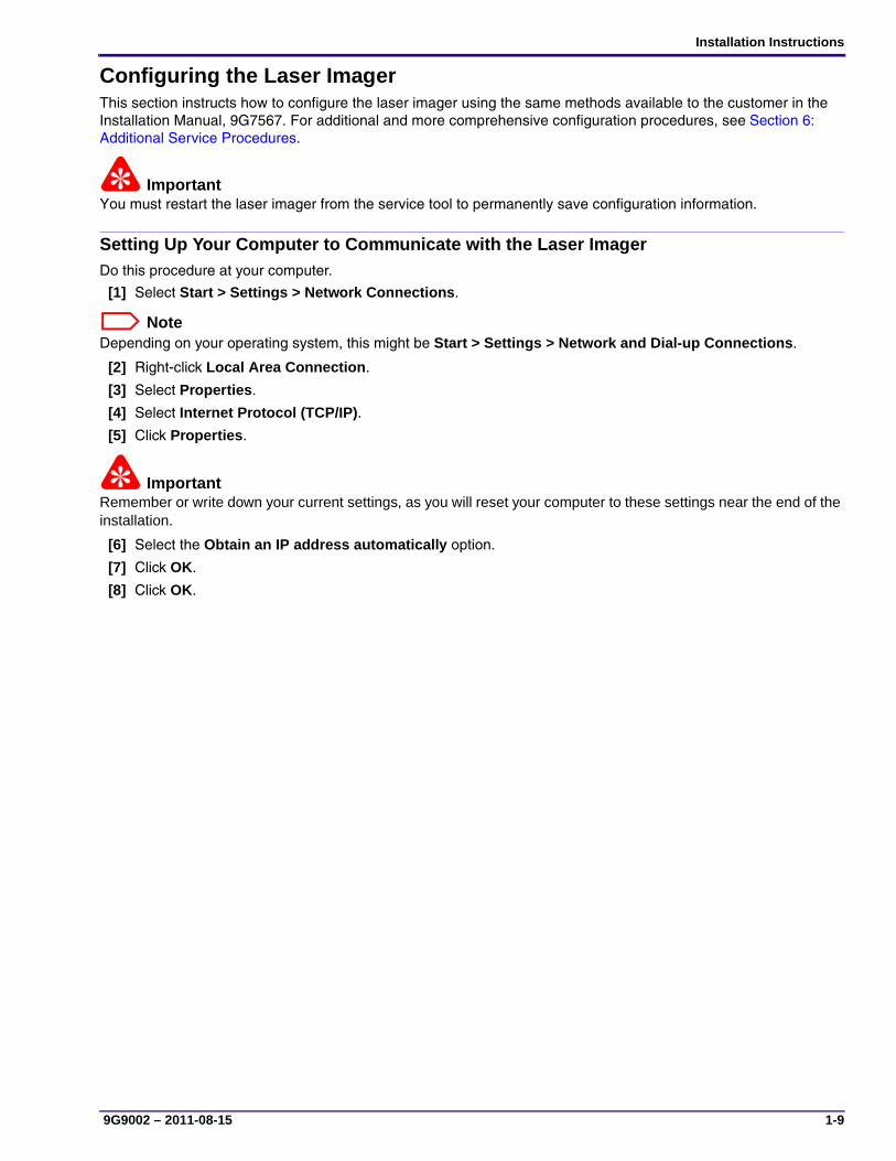
Configuring Site-Specific Information
ImportantTo modify the configuration settings for several areas in this section, you must be logged on to the service tool via Secure Link.
[1] Log on to your Secure Link account.
[2] Make sure that the IP address in the Secure Link window matches the service portal: 192.168.0.1.
[3] Launch the Web Service Portal Software (Web Portal).
The main screen for the service tool displays.
NoteIf you are using INTERNET EXPLORER 8, set the browser window to Compatibility View: Click the Compatibility View toolbar button. This corrects some potential viewing issues with IE8. If the icon is not on the toolbar, select Tools > Compatibility View from the browser menu.
[4] Select Wizards > Installation Assistant.
[5] Click at the bottom of the screen. The Network Configuration screen appears.
[6] Enter:
• Host Name
• IP Address
• Subnet Mask
• Default Gateway
NoteThis information should have been gathered on the Pre-installation Manual. If you need help, see the network administrator.
[7] Click Save.
[8] Click . The Clock Configuration screen appears.
ImportantThe system clock is set before the laser imager is shipped to you. If the time zone is not correct, change it. When you change the time zone, the time and date display correctly.
[9] Are the time zone, date, and time correct?
Yes No
Advance to Step 11. Continue with the next step.

SERVICE MANUAL
1-12 9G9002 – 2011-08-15
[10] Will you set the clock manually, or does the site use a time server for synchronization?
[11] Click . The System Identification screen appears.
NoteCompleting this screen is optional.
[12] Enter the following information:
• Country Code
• Postal Code
• Hospital Name
• Department Name
• Device Location
[13] Click Save.
[14] Click to return to the main screen.
[15] Select Utilities > Session > Restart, and then click Restart.
NoteMake sure to restart using these steps or the network parameters will not be saved.
Wait for the laser imager to restart. The laser imager requires approximately 30 minutes to warm up. After completing the warm-up cycle, the laser imager may print a calibration film if the film cartridge requires it. While the laser imager is warming up, continue with the next step.
Manually Synchronization
a. Select the time zone.
b. Edit the time if needed.
c. Click Save.
a. Select the Enable Time Synchronization check box.
b. In the IP Address field, type the address of the time server to be used for synchronization.
c. In the Period field, select the synchronization period (how often the clock is synchronized) from the drop-down menu.
d. Select the time zone.
e. Click Save.

Installation Instructions
A4A9YG220B_111019 1-13
Completing the InstallationChecking Image Quality
[1] Connect the network cable to the:
• Network connector on the laser imager.
• Nearest active building network connector.
[2] After the laser imager has completed the warm-up cycle, send an image from each modality that will print to the laser imager.
[3] If the image quality must be improved for a modality, optimize the images from that modality:
(a) From the main screen, select Wizards > Image Quality.
(b) Cancel all pending print jobs or wait until all print jobs are printed.
(c) Under Optimization Steps, click .
(d) Send an image from the modality, and then click .
NoteThe image does not print until you click the button.
(e) View the test print and visually select the optimal image.
(f) Under Image Number, click to select the number of your optimal image.
(g) Under Optimization Steps, click again to continue.
(h) Check the status and result data near the bottom of the screen.
(i) Send another image from the modality and check the print.
NoteIf none of the images are optimal for the site, see Additional Service Procedures, “Checking Image Quality”.
[4] Continue with “Backing Up the System Configuration”.
Laser Imager Back Cover
Network Connector
NoteThe default port No. of the laser imager is set to 5040.

SERVICE MANUAL
1-14 9G9002 – 2011-08-15
Backing Up the System ConfigurationFor the laser imager:
[1] Select: Utilities > Backup/Restore.
[2] To make a backup of the configuration parameters to the DRE flash drive, click Backup.
[3] To download the backup data to your laptop computer:
(a) Click Download Backup.
(b) Click Save in the confirmation window.
(c) Select a folder name to place the file in.
(d) Click Save to place the backup file in the selected folder.
[4] Log off from the service tool (see Additional Service Procedures, “Logging Off the Service Tool”).
[5] Remove the top cover.
[6] Disconnect the crossover cable and restore the settings to your computer if necessary.
[7] Install the top cover.
Discarding Excess MaterialWhen you are finished and the laser imager is operational, discard all excess shipping materials in a manner suitable to local ordinances.
Instructing the OperatorBefore you leave the installation site, instruct the operator:
• How to load film into the laser imager.
• How to change the deodorant filter on the laser imager.
• To read the Safety Manual, 9G7565, and the Operation Manual, 9G7564.

Installation Instructions
9G9002 – 2011-08-15 1-15
Troubleshooting
Laser Imager Does Not Start
CautionNever pull on the cord to disconnect the plug from the wall outlet. Grasp the plug and pull to disconnect.
[1] Press the power switch on the back of the laser imager off (0), and then on (|), to restart the laser imager.
If this does not solve the problem, continue with Step 2.
[2] Disconnect the power cord from the wall outlet.
[3] Check that the power cord is properly connected to the AC power connector on the laser imager.
[4] Plug the power cord into the wall outlet.
[5] Check that the wall outlet is energized.
Error CodesThe following codes might appear during the installation. If so, see the table to resolve them. For a complete list of error codes, see Diagnostics, “Condition Codes”.
NoteAs shown in the table, the same code appears as a 3-digit number on the display screen and as a 5-digit number at the Web Portal. See Diagnostics, “Condition Codes” for more information.
Display Screen Web Portal Web Portal Message Action
006 20006 Disconnected or Faulty Network Cable
Check and reconnect the network cable on both ends. Try a different cable. Check that the network is functioning at your site. If the error persists, call for service.
209 20209 Laser Imager Opened During Self Test
Close the cover. Restart the laser imager. If the error persists, call for service.
701 20701 none Close the cover.
704 20704 none The network connection to the laser imager has been lost. Restart the laser imager.
175 21175 Rollback Failed to Engage Cartridge
If the Pause symbol is on, press it to cover the film cartridge. When the Pause symbol stops flashing, remove the film cartridge from the laser imager. Insert a different film cartridge into the laser imager. If the error persists, call for service.

SERVICE MANUAL
1-16 9G9002 – 2011-08-15
This page is intentionally blank.
Adjustments and Replacements
9G9002 – 2011-08-15 2-1
Section 2: Adjustments and Replacements
Processor—Drum Temperature Adjustment
Adjustment Specification
Note• A temperature meter and probe with a bar type element must be used for this procedure. Probes with circular
type elements will not provide correct readings. The temperature meter and probe must be calibrated together, at least once per year. If the probe breaks, a new probe and the existing meter must be calibrated again.
• The temperature meter must be at room temperature during this procedure. If the meter has been in a hot or cold vehicle, allow it to adjust to room temperature before using.
Purpose: To set the correct temperature for the drum
Setting Temperature: This procedure is required after replacing the processor assembly, processor drum, or the DRE board, or if you expect that drum temperatures are causing image quality problems.
Specification: The temperature at the processor drum must be between 123.5–124.5 °C.
Special Tools: • Temperature meter with probe
• Block for probe, kit
• Laptop computer with MICROSOFT INTERNET EXPLORER
• Service tool
• Crossover cable
Prerequisites None

SERVICE MANUAL
2-2 9G9002 – 2011-08-15
To Check:[1] Energize the laser imager and let it warm to operating temperature.
[2] Prepare the meter:
(a) Install the block on the probe 140.0 mm (5.5 in.) from the probe sensor.
(b) Clean the probe with alcohol wipes.
(c) Set the meter to display in °C.
[3] Remove the back cover.
Block
Probe Sensor
Probe
Meter
140.0 mm (5.5 in.)

Adjustments and Replacements
9G9002 – 2011-08-15 2-3
[4] Insert the probe into the slot on the left rear of the processor assembly, feed it upward, and let the rotation of the processor drum pull the probe until the block reaches the slot.
NoteIf the laser imager is in Standby mode, the processor drum pulls the probe very slowly and it may be difficult to detect movement.
[5] Allow the temperature reading on the meter to stabilize. This requires approximately 90 seconds.
[6] Check that the temperature at the processor drum is between 123.5–124.5 °C.
[7] Pull back slightly, 1.0–2.0 cm (0.4–0.8 in.), on the block to confirm that the highest temperature is being read.
[8] Is the temperature within specification?
Yes No
Remove the probe, and then install the back cover.
Note the highest temperature reading, and then perform the drum temperature adjustment procedure.
Probe
Slot
Processor Assembly
Drum
SERVICE MANUAL
2-4 9G9002 – 2011-08-15
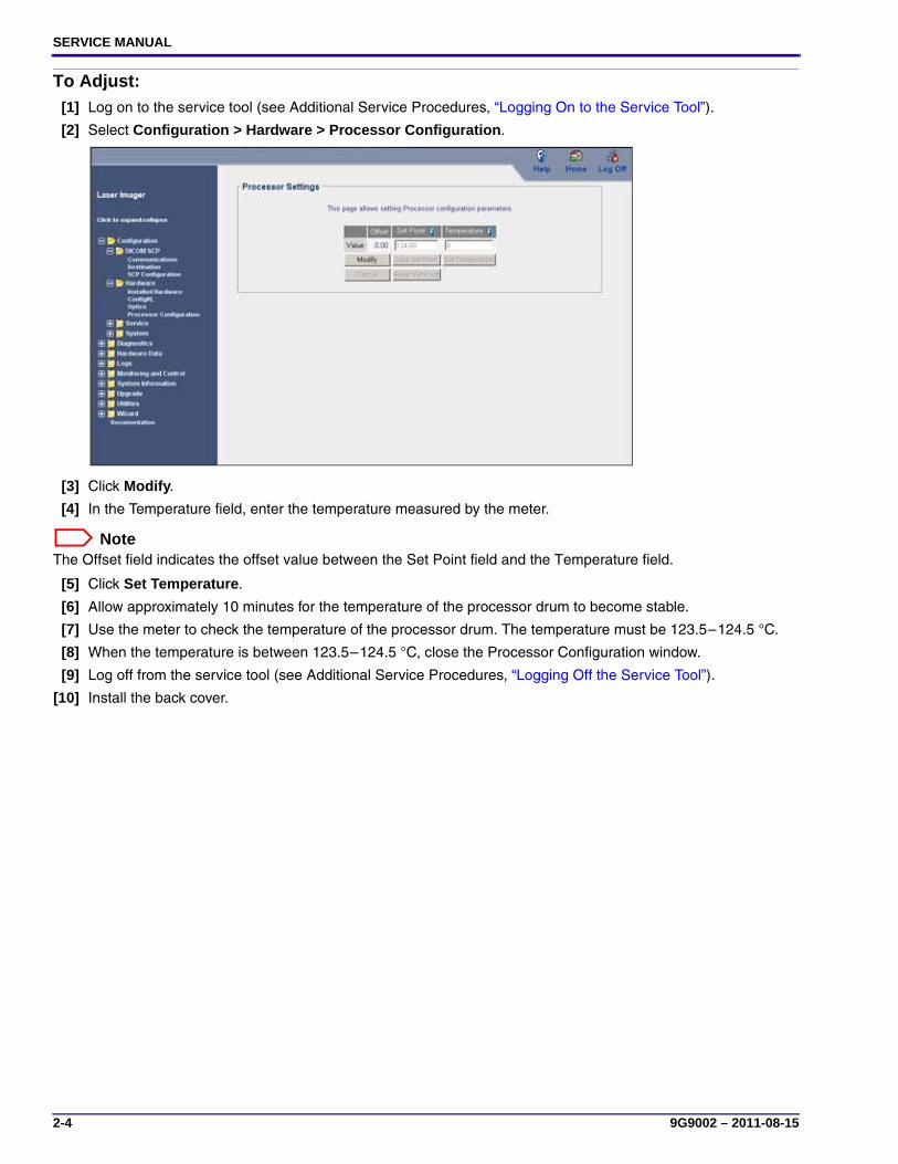
To Adjust:[1] Log on to the service tool (see Additional Service Procedures, “Logging On to the Service Tool”).
[2] Select Configuration > Hardware > Processor Configuration.
[3] Click Modify.
[4] In the Temperature field, enter the temperature measured by the meter.
NoteThe Offset field indicates the offset value between the Set Point field and the Temperature field.
[5] Click Set Temperature.
[6] Allow approximately 10 minutes for the temperature of the processor drum to become stable.
[7] Use the meter to check the temperature of the processor drum. The temperature must be 123.5–124.5 °C.
[8] When the temperature is between 123.5–124.5 °C, close the Processor Configuration window.
[9] Log off from the service tool (see Additional Service Procedures, “Logging Off the Service Tool”).
[10] Install the back cover.
Adjustments and Replacements
9G9002 – 2011-08-15 2-5
Imaging Assembly—Start Index Delay Adjustment
Adjustment Specification
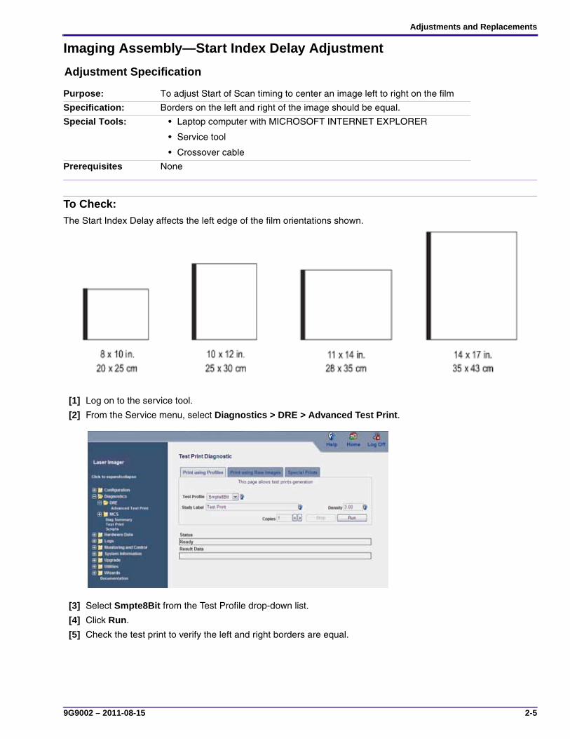
To Check:The Start Index Delay affects the left edge of the film orientations shown.
[1] Log on to the service tool.
[2] From the Service menu, select Diagnostics > DRE > Advanced Test Print.
[3] Select Smpte8Bit from the Test Profile drop-down list.
[4] Click Run.
[5] Check the test print to verify the left and right borders are equal.
Purpose: To adjust Start of Scan timing to center an image left to right on the film
Specification: Borders on the left and right of the image should be equal.
Special Tools: • Laptop computer with MICROSOFT INTERNET EXPLORER
• Service tool
• Crossover cable
Prerequisites None
SERVICE MANUAL
2-6 9G9002 – 2011-08-15
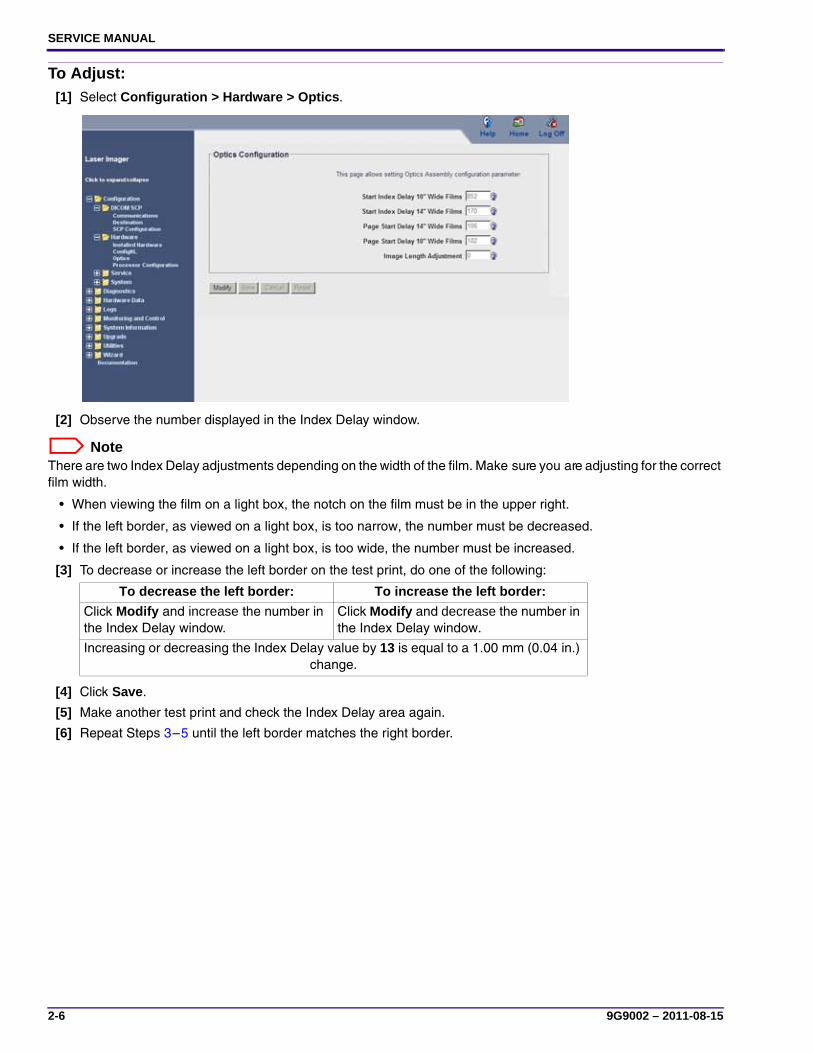
To Adjust:[1] Select Configuration > Hardware > Optics.
[2] Observe the number displayed in the Index Delay window.
NoteThere are two Index Delay adjustments depending on the width of the film. Make sure you are adjusting for the correct film width.
• When viewing the film on a light box, the notch on the film must be in the upper right.
• If the left border, as viewed on a light box, is too narrow, the number must be decreased.
• If the left border, as viewed on a light box, is too wide, the number must be increased.
[3] To decrease or increase the left border on the test print, do one of the following:
[4] Click Save.
[5] Make another test print and check the Index Delay area again.
[6] Repeat Steps 3–5 until the left border matches the right border.
To decrease the left border: To increase the left border:
Click Modify and increase the number in the Index Delay window.
Click Modify and decrease the number in the Index Delay window.
Increasing or decreasing the Index Delay value by 13 is equal to a 1.00 mm (0.04 in.) change.
Adjustments and Replacements
9G9002 – 2011-08-15 2-7
Imaging Assembly—Page Start Adjustment
Adjustment Specification
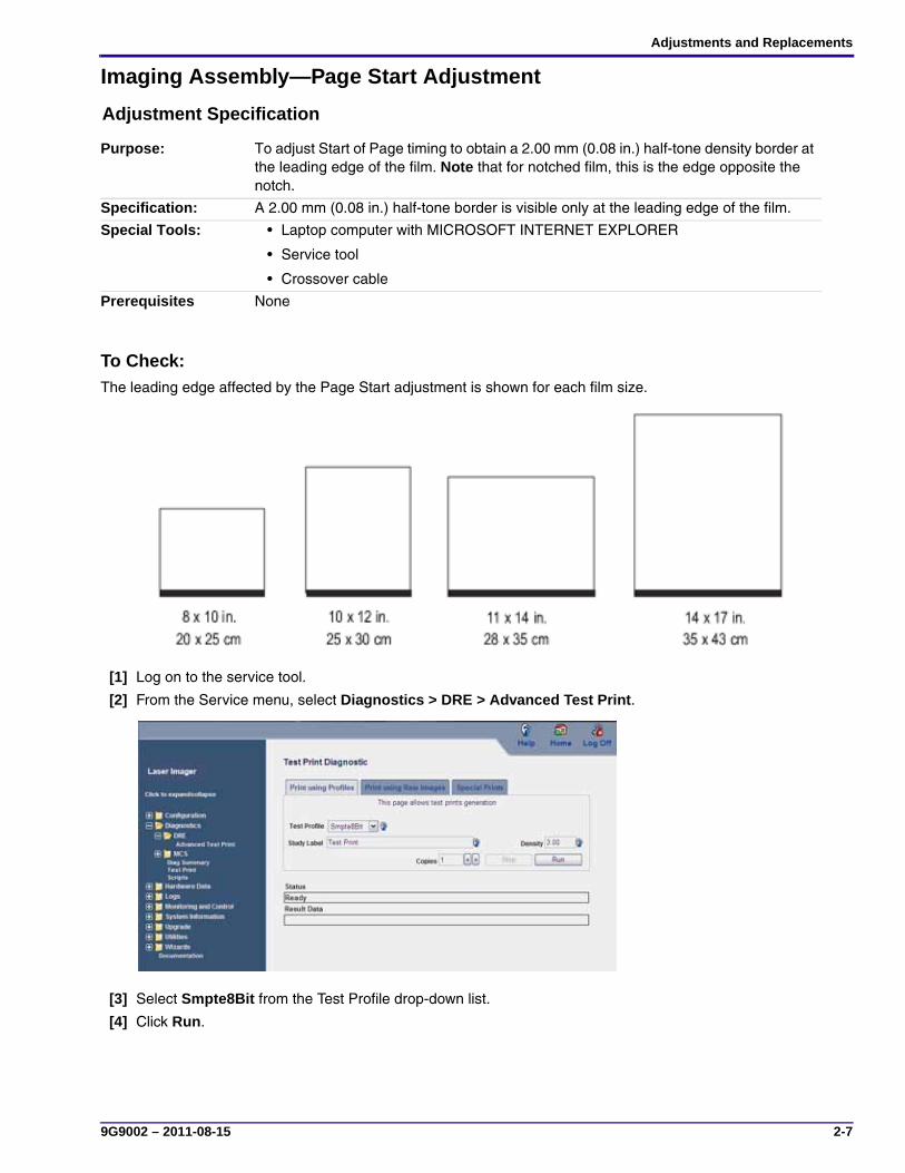
To Check:The leading edge affected by the Page Start adjustment is shown for each film size.
[1] Log on to the service tool.
[2] From the Service menu, select Diagnostics > DRE > Advanced Test Print.
[3] Select Smpte8Bit from the Test Profile drop-down list.
[4] Click Run.
Purpose: To adjust Start of Page timing to obtain a 2.00 mm (0.08 in.) half-tone density border at the leading edge of the film. Note that for notched film, this is the edge opposite the notch.
Specification: A 2.00 mm (0.08 in.) half-tone border is visible only at the leading edge of the film.
Special Tools: • Laptop computer with MICROSOFT INTERNET EXPLORER
• Service tool
• Crossover cable
Prerequisites None

SERVICE MANUAL
2-8 9G9002 – 2011-08-15
[5] Check for a 2.00 mm (0.08 in.) half-tone density at the leading edge of the film with no transparent area appearing.
To Adjust:[1] Select Configuration > Hardware > Optics.
[2] Observe the number displayed in the Page Start Delay window.
NoteThere are two Page Start Delay adjustments depending on the width of the film. Make sure you are adjusting for the correct film width.
• When viewing the film on a light box, make sure you are looking at the leading edge.
• If the half-tone density, as viewed on a light box, is less than 2 mm, the number must be decreased.
• If the half-tone density, as viewed on a light box, is greater than 2 mm, the number must be increased.
[3] To decrease or increase the half-tone density border on the test print, do one of the following:
[4] Click Save.
[5] Make another test print and check the Page Start Delay area again.
[6] Repeat Steps 3–5 until the half-tone density border is within specification.
To increase the border: To decrease the border:
Click Modify and decrease the number in the Page Start Delay window.
Click Modify and increase the number in the Index Delay window.
Increasing or decreasing the Page Start Delay value by 13 is equal to a 1.00 mm (0.04 in.) change.
Printing above half-tone border
2.00 mm (0.08 in.) half-tone density border
Correct Incorrect
Adjustments and Replacements
9G9002 – 2011-08-15 2-9
Top Cover
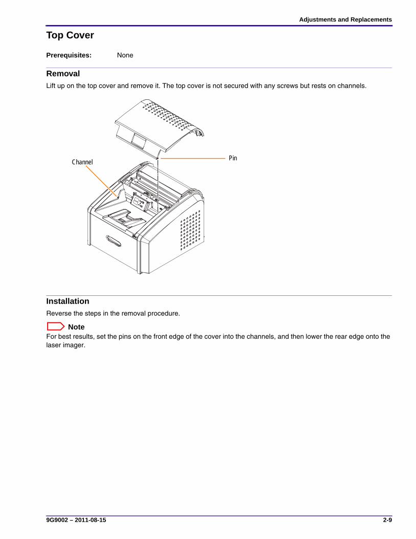
RemovalLift up on the top cover and remove it. The top cover is not secured with any screws but rests on channels.
InstallationReverse the steps in the removal procedure.
NoteFor best results, set the pins on the front edge of the cover into the channels, and then lower the rear edge onto the laser imager.
Prerequisites: None
PinChannel

SERVICE MANUAL
2-10 9G9002 – 2011-08-15
Left cover
Removal[1] Remove the top cover.
[2] Loosen the captive thumb screw.
[3] Open the film supply.
[4] Loosen the captive thumb screw located under the exit tray.
[5] Remove the left cover.
InstallationReverse the steps in the removal procedure.
Prerequisites: • Close the film cartridge. (Touch the Pause button on the display screen.)
• De-energize the laser imager.
• Disconnect the power cord.
Captive Thumb ScrewCaptive Thumb Screw
Captive Thumb ScrewCaptive Thumb Screw
Adjustments and Replacements
9G9002 – 2011-08-15 2-11
Right Cover
Removal
CautionCautionRisk of electric shock: Dangerous voltage present.
[1] Remove the top cover and open the film supply.
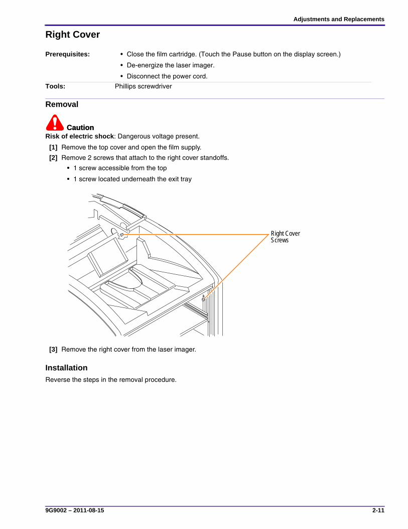
[2] Remove 2 screws that attach to the right cover standoffs.
• 1 screw accessible from the top
• 1 screw located underneath the exit tray
[3] Remove the right cover from the laser imager.
InstallationReverse the steps in the removal procedure.
Prerequisites: • Close the film cartridge. (Touch the Pause button on the display screen.)
• De-energize the laser imager.
• Disconnect the power cord.
Tools: Phillips screwdriver
H221_6003AC
Right Cover Screws
SERVICE MANUAL
2-12 9G9002 – 2011-08-15
Back cover
Removal
CautionCautionRisk of electric shock: Dangerous voltage present.
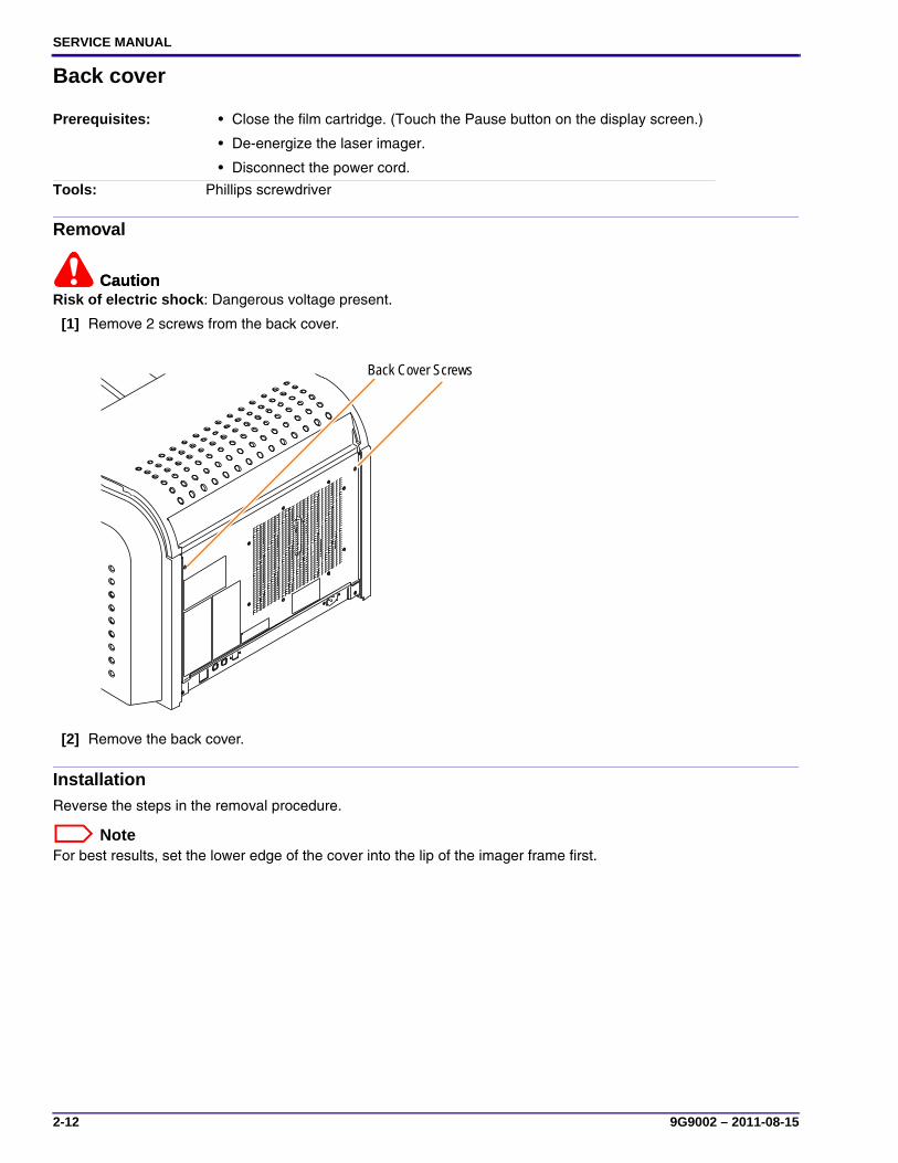
[1] Remove 2 screws from the back cover.
[2] Remove the back cover.
InstallationReverse the steps in the removal procedure.
NoteFor best results, set the lower edge of the cover into the lip of the imager frame first.
Prerequisites: • Close the film cartridge. (Touch the Pause button on the display screen.)
• De-energize the laser imager.
• Disconnect the power cord.
Tools: Phillips screwdriver
Back Cover Screws

Adjustments and Replacements
9G9002 – 2011-08-15 2-13
Display Screen Assembly
To Remove:[1] Disconnect the connector from the left side of the display screen.
[2] Remove 4 screws that hold the electronics board to the mounting bracket.
InstallationReverse the steps in the removal procedure.
Prerequisites: • Close the film cartridge. (Touch the Pause button on the display screen.)
• De-energize the laser imager.
• Disconnect the power cord.
• Remove the top cover.
Tools: T10 Torx driver
Display Screen
Screws
SERVICE MANUAL
2-14 9G9002 – 2011-08-15
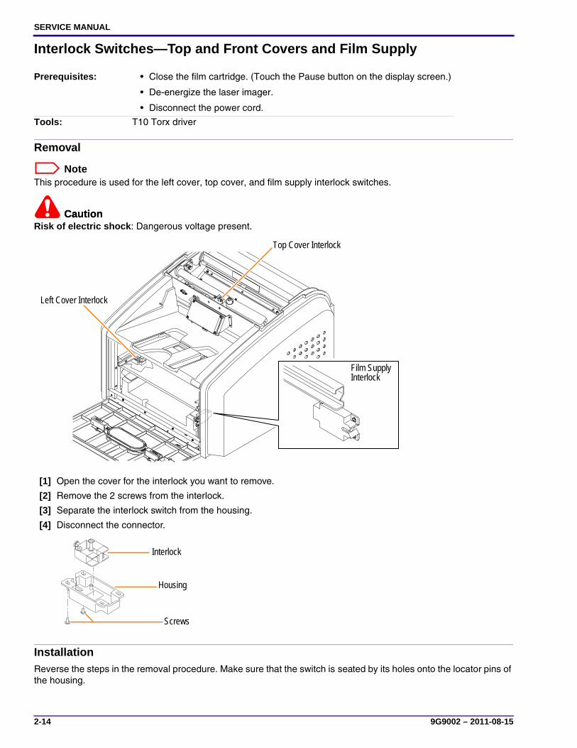
Interlock Switches—Top and Front Covers and Film Supply
Removal
NoteThis procedure is used for the left cover, top cover, and film supply interlock switches.
CautionCautionRisk of electric shock: Dangerous voltage present.
[1] Open the cover for the interlock you want to remove.
[2] Remove the 2 screws from the interlock.
[3] Separate the interlock switch from the housing.
[4] Disconnect the connector.
InstallationReverse the steps in the removal procedure. Make sure that the switch is seated by its holes onto the locator pins of the housing.
Prerequisites: • Close the film cartridge. (Touch the Pause button on the display screen.)
• De-energize the laser imager.
• Disconnect the power cord.
Tools: T10 Torx driver
H221_6004HC
Top Cover Interlock
Film Supply Interlock
Left Cover Interlock
H221_6005ACScrews
Housing
Interlock
Adjustments and Replacements
9G9002 – 2011-08-15 2-15
Processor Drum
Removal
CautionHot Surface: When the laser imager is initially de-energized, the processor drum and rollers are hot. Take care when removing the processor drum.
CautionBe sure to loosen the correct screws. Loosening the wrong screws will cause the bearings or the springs in the retainer to become loose and difficult to reset.
Prerequisites: • Close the film cartridge. (Touch the Pause button on the display screen.)
• De-energize the laser imager.
• Disconnect the power cord.
• Remove:
– Top cover
– Right cover
– Left cover
Tools: T10 Torx driver
SERVICE MANUAL
2-16 9G9002 – 2011-08-15
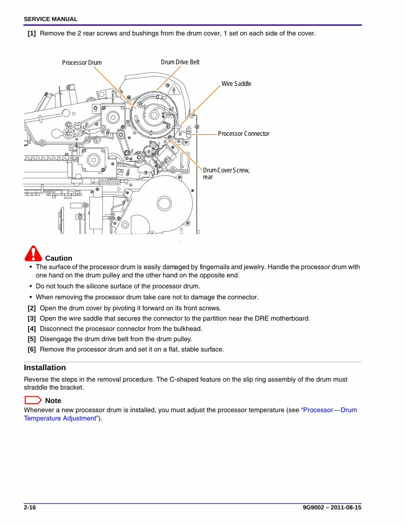
[1] Remove the 2 rear screws and bushings from the drum cover, 1 set on each side of the cover.
Caution• The surface of the processor drum is easily damaged by fingernails and jewelry. Handle the processor drum with
one hand on the drum pulley and the other hand on the opposite end.
• Do not touch the silicone surface of the processor drum.
• When removing the processor drum take care not to damage the connector.
[2] Open the drum cover by pivoting it forward on its front screws.
[3] Open the wire saddle that secures the connector to the partition near the DRE motherboard.
[4] Disconnect the processor connector from the bulkhead.
[5] Disengage the drum drive belt from the drum pulley.
[6] Remove the processor drum and set it on a flat, stable surface.
InstallationReverse the steps in the removal procedure. The C-shaped feature on the slip ring assembly of the drum must straddle the bracket.
NoteWhenever a new processor drum is installed, you must adjust the processor temperature (see “Processor—Drum Temperature Adjustment”).
Drum Cover Screw, rear
Processor Drum
Wire Saddle
Processor Connector
Drum Drive Belt
Adjustments and Replacements
9G9002 – 2011-08-15 2-17
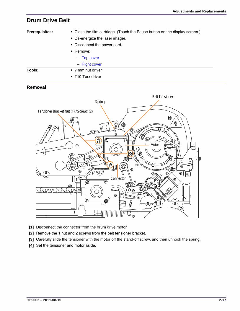
Drum Drive Belt
Removal
[1] Disconnect the connector from the drum drive motor.
[2] Remove the 1 nut and 2 screws from the belt tensioner bracket.
[3] Carefully slide the tensioner with the motor off the stand-off screw, and then unhook the spring.
[4] Set the tensioner and motor aside.
Prerequisites: • Close the film cartridge. (Touch the Pause button on the display screen.)
• De-energize the laser imager.
• Disconnect the power cord.
• Remove:
– Top cover
– Right cover
Tools: • 7 mm nut driver
• T10 Torx driver
Belt TensionerSpring
Tensioner Bracket Nut (1) / Screws (2)
Connector
Motor

SERVICE MANUAL
2-18 9G9002 – 2011-08-15
[5] Remove the drum drive belt from the exit pulley.
[6] To remove the belt completely, you must free it from the processor drum pulley:
(a) Open the wire saddle and disconnect the drum drive connector.
(b) Remove the front screw and loosen the rear screw on the drum drive bracket.
(c) Pivot the drum drive bracket toward the back of the imager and remove the belt from the pulley.
Installation[1] Slide the belt over the processor drum pulley.
[2] Pivot the drum drive bracket back into place. Make sure that the C-shaped feature on the slip ring assembly straddles the bracket.
[3] Install and tighten the 2 bracket screws.
[4] Connect the drum drive connector.
[5] Hold the tensioner in position and place the belt over the exit pulley and the tensioner pulley.
• The bottom of the belt sits on the top of the tensioner pulley.
• The top of the belt runs just underneath the top of the tensioner bracket.
[6] Set the tensioner onto the end of the screw and attach the spring.
[7] Slide the tensioner completely into place, and then install the 1 nut and 2 screws.
[8] Connect the connector to the drum drive motor.
[9] Install the covers.
NoteThe teeth on the belt must mesh properly with the teeth on the pulley. The longest span of the belt should deflect a maximum of 1.27 cm (0.50 in.) when finger pressure is applied.
Drum Drive Connector
Drum Drive Bracket Screws
Exit Pulley
Drum Drive Belt
Slip Ring Assembly
Wire Saddle
Processor Drum Pulley
Adjustments and Replacements
9G9002 – 2011-08-15 2-19
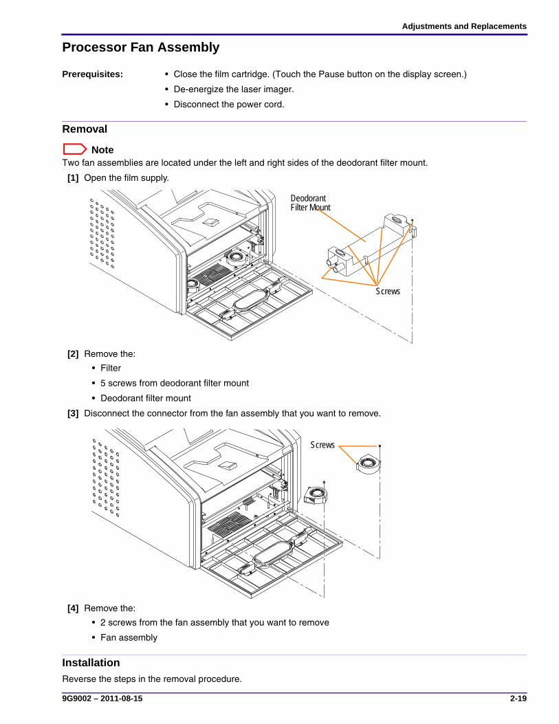
Processor Fan Assembly
Removal
NoteTwo fan assemblies are located under the left and right sides of the deodorant filter mount.
[1] Open the film supply.
[2] Remove the:
• Filter
• 5 screws from deodorant filter mount
• Deodorant filter mount
[3] Disconnect the connector from the fan assembly that you want to remove.
[4] Remove the:
• 2 screws from the fan assembly that you want to remove
• Fan assembly
InstallationReverse the steps in the removal procedure.
Prerequisites: • Close the film cartridge. (Touch the Pause button on the display screen.)
• De-energize the laser imager.
• Disconnect the power cord.
H221_6007BC
Deodorant Filter Mount
Screws
H221 6008BC
Screws

SERVICE MANUAL
2-20 9G9002 – 2011-08-15
Felt Pad Assembly
Removal
CautionHot Surface: When the laser imager is initially de-energized, the processor drum rollers are hot. Take care when working in the area of the processor.
[1] De-energize the laser imager.
[2] Loosen the 2 captive thumb screws on the heat shield, and then lift the heat shield open.
[3] Remove the:
• 2 screws that hold the felt pad assembly to the cooling plate
• Felt pad assembly
Prerequisites: • Close the film cartridge. (Touch the Pause button on the display screen.)
• De-energize the laser imager.
• Disconnect the power cord.
• Remove:
– Top cover
– Left cover
Captive Thumb Screws
Felt Pad Assembly Screw (1 of 2)
Felt Pad Assembly
Heat Shield
Cooling Plate

Adjustments and Replacements
9G9002 – 2011-08-15 2-21
Installation[1] Fit the edge of the felt pad into the channel of the film diverter assembly.
[2] Install and tighten the 2 screws.
[3] Close the heat shield and tighten the captive screws.
[4] Install the top cover and the left cover.
[5] Connect the power cord, and then energize the imager.
SERVICE MANUAL
2-22 9G9002 – 2011-08-15
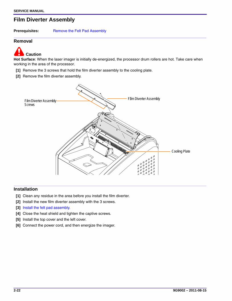
Film Diverter Assembly
Removal
CautionHot Surface: When the laser imager is initially de-energized, the processor drum rollers are hot. Take care when working in the area of the processor.
[1] Remove the 3 screws that hold the film diverter assembly to the cooling plate.
[2] Remove the film diverter assembly.
Installation[1] Clean any residue in the area before you install the film diverter.
[2] Install the new film diverter assembly with the 3 screws.
[3] Install the felt pad assembly.
[4] Close the heat shield and tighten the captive screws.
[5] Install the top cover and the left cover.
[6] Connect the power cord, and then energize the imager.
Prerequisites: Remove the Felt Pad Assembly
Film Diverter Assembly Screws
FIlm Diverter Assembly
Cooling Plate

Adjustments and Replacements
9G9002 – 2011-08-15 2-23
Processor Cover
Removal
ImportantThe bearings on the ends of each roller are loose. Be sure to remove the correct screws at the side of the processor. Loosening the wrong screws will cause the bearings or the springs in the retainer to become loose and difficult to reset.
[1] Remove 2 screws and bushings on each side of the processor cover.
NoteThe front retaining rod is held in place by the front screws and is free after you remove them.
[2] Remove the processor cover.
InstallationReverse the steps in the removal procedure. Make sure that the front retaining rod is secured when you install the front screws of the cover.
Prerequisites: • Close the film cartridge. (Touch the Pause button on the display screen.)
• De-energize the laser imager.
• Disconnect the power cord.
• Remove:
– Top cover
– Right cover
– Left cover
Tools: T10 Torx driver
Drum Cover Screw, rear
Processor Drum
Drum Cover Screw, front

SERVICE MANUAL
2-24 9G9002 – 2011-08-15
Densitometer Assembly
Removal[1] Open the heat shield, and then remove the felt pad assembly (see “Felt Pad Assembly”).
[2] Disconnect the connector on the top of the cooling assembly.
[3] Disconnect the connector on the bottom of the cooling assembly from the main wiring harness.
Prerequisites: • Close the film cartridge. (Touch the Pause button on the display screen.)
• De-energize the laser imager.
• Disconnect the power cord.
• Remove:
– Top cover
– Right cover
– Left cover
H221_6033GC
Connector, top
Cooling Assembly Lower Screw
Cooling Assembly Lower Screw
Cooling Assembly Brackets
Connector, bottom
Cooling Assembly

Adjustments and Replacements
9G9002 – 2011-08-15 2-25
[4] Remove the:
• 2 screws and left cooling assembly bracket
• 2 screws and right cooling assembly bracket
• Lower 2 screws of the cooling assembly
[5] Remove the cooling assembly and densitometer, and pull the attached cable harness through the frame.
InstallationReverse the steps in the removal procedure.
SERVICE MANUAL
2-26 9G9002 – 2011-08-15
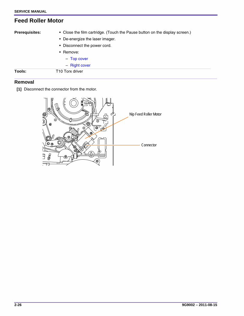
Feed Roller Motor
Removal[1] Disconnect the connector from the motor.
Prerequisites: • Close the film cartridge. (Touch the Pause button on the display screen.)
• De-energize the laser imager.
• Disconnect the power cord.
• Remove:
– Top cover
– Right cover
Tools: T10 Torx driver
Nip Feed Roller Motor
Connector
Adjustments and Replacements
9G9002 – 2011-08-15 2-27
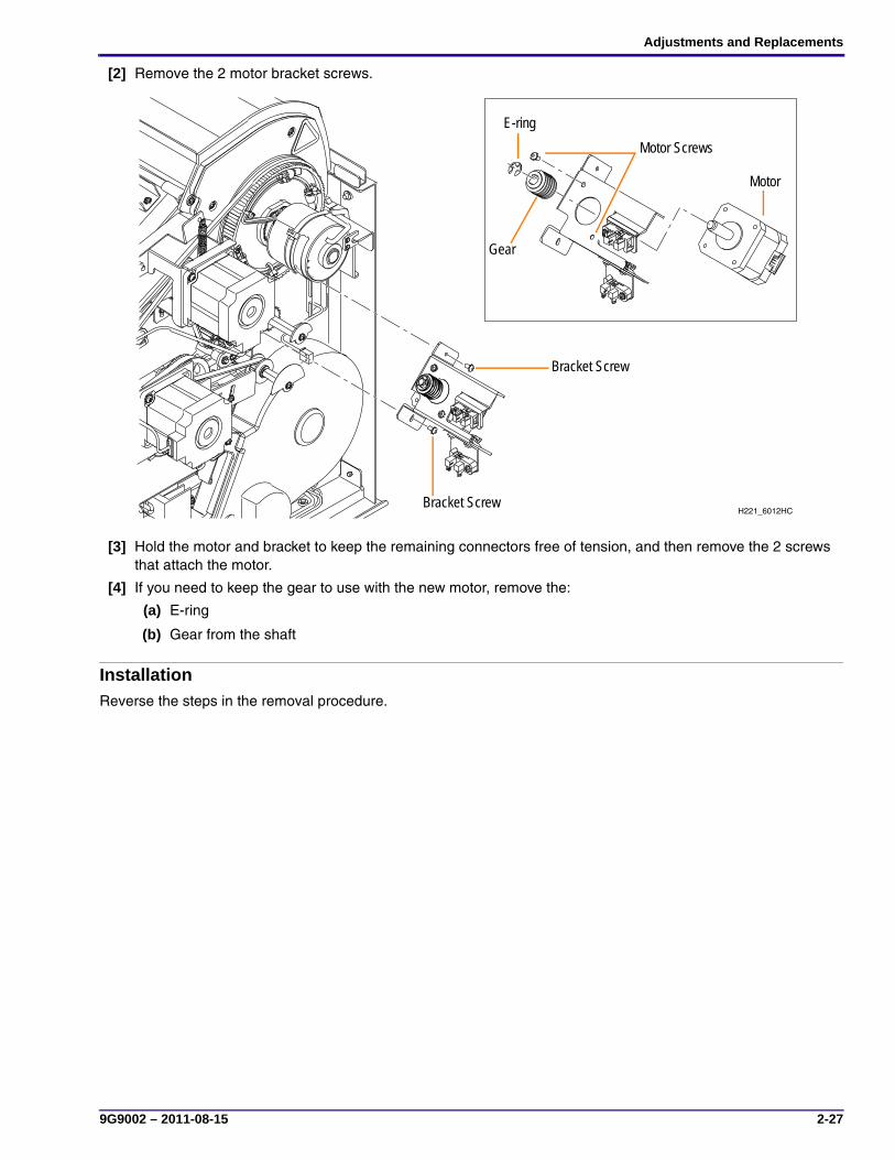
[2] Remove the 2 motor bracket screws.
[3] Hold the motor and bracket to keep the remaining connectors free of tension, and then remove the 2 screws that attach the motor.
[4] If you need to keep the gear to use with the new motor, remove the:
(a) E-ring
(b) Gear from the shaft
InstallationReverse the steps in the removal procedure.
H221_6012HCBracket Screw
Bracket Screw
Motor ScrewsE-ring
Gear
Motor
SERVICE MANUAL
2-28 9G9002 – 2011-08-15
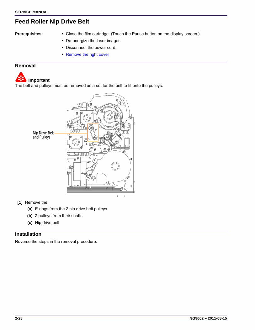
Feed Roller Nip Drive Belt
Removal
ImportantThe belt and pulleys must be removed as a set for the belt to fit onto the pulleys.
[1] Remove the:
(a) E-rings from the 2 nip drive belt pulleys
(b) 2 pulleys from their shafts
(c) Nip drive belt
InstallationReverse the steps in the removal procedure.
Prerequisites: • Close the film cartridge. (Touch the Pause button on the display screen.)
• De-energize the laser imager.
• Disconnect the power cord.
• Remove the right cover
HC
Nip Drive Belt and Pulleys
Adjustments and Replacements
9G9002 – 2011-08-15 2-29
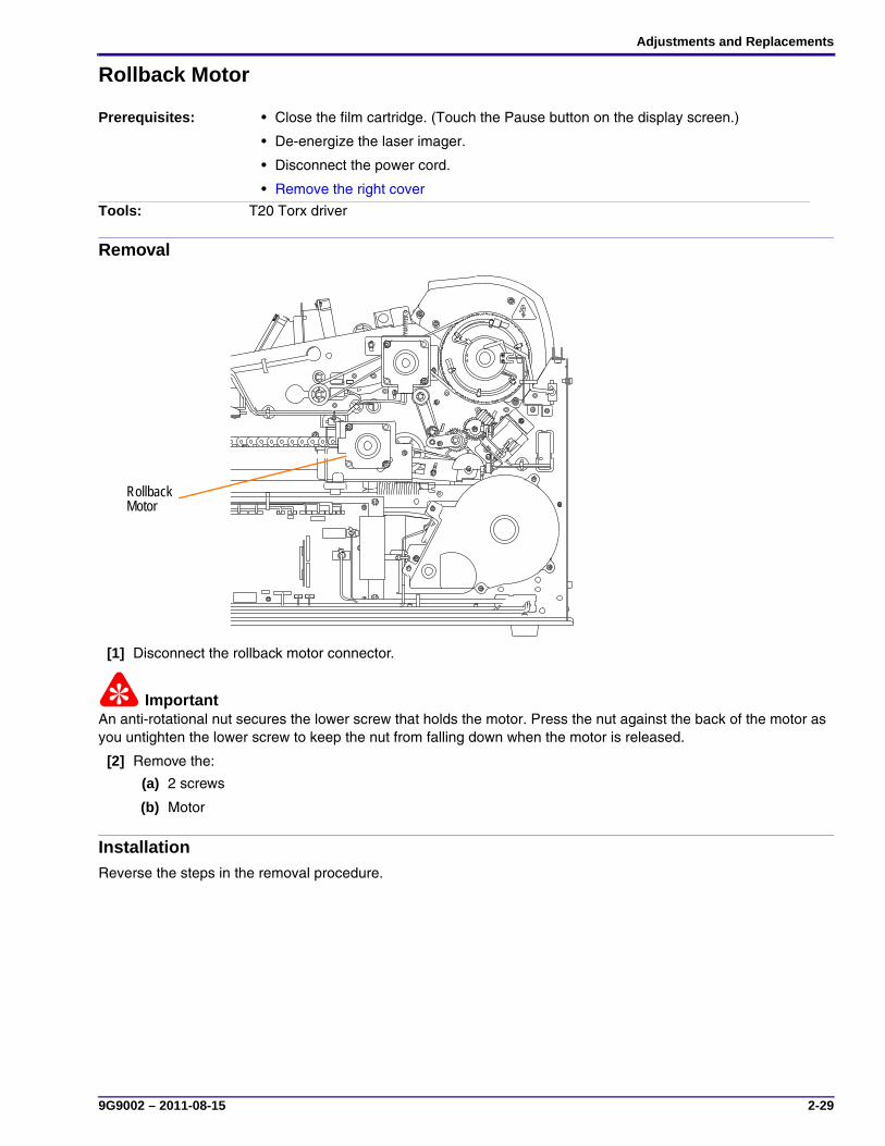
Rollback Motor
Removal
[1] Disconnect the rollback motor connector.
ImportantAn anti-rotational nut secures the lower screw that holds the motor. Press the nut against the back of the motor as you untighten the lower screw to keep the nut from falling down when the motor is released.
[2] Remove the:
(a) 2 screws
(b) Motor
InstallationReverse the steps in the removal procedure.
Prerequisites: • Close the film cartridge. (Touch the Pause button on the display screen.)
• De-energize the laser imager.
• Disconnect the power cord.
• Remove the right cover
Tools: T20 Torx driver
H221_6006HC
Rollback Motor
SERVICE MANUAL
2-30 9G9002 – 2011-08-15
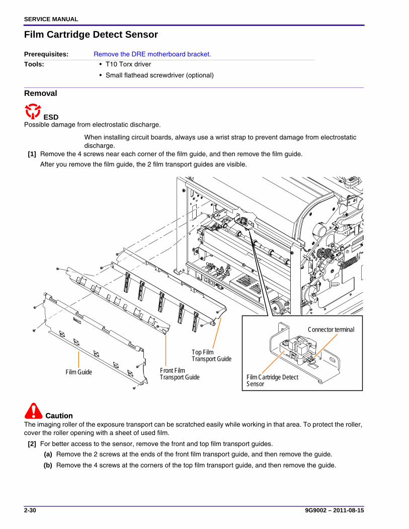
Film Cartridge Detect Sensor
Removal
Possible damage from electrostatic discharge.ESD
When installing circuit boards, always use a wrist strap to prevent damage from electrostatic discharge.
[1] Remove the 4 screws near each corner of the film guide, and then remove the film guide.
After you remove the film guide, the 2 film transport guides are visible.
CautionCautionThe imaging roller of the exposure transport can be scratched easily while working in that area. To protect the roller, cover the roller opening with a sheet of used film.
[2] For better access to the sensor, remove the front and top film transport guides.
(a) Remove the 2 screws at the ends of the front film transport guide, and then remove the guide.
(b) Remove the 4 screws at the corners of the top film transport guide, and then remove the guide.
Prerequisites: Remove the DRE motherboard bracket.
Tools: • T10 Torx driver
• Small flathead screwdriver (optional)
H221_6013HC
Film Guide
Top Film Transport Guide
Front Film Transport Guide Film Cartridge Detect
Sensor
Connector terminal

Adjustments and Replacements
9G9002 – 2011-08-15 2-31
[3] Remove the connector from the film cartridge detect sensor.
NoteThe connector position is tight. You might need to use a small flathead screwdriver to remove the connector.
[4] Remove the sensor screw and then remove the film cartridge detect sensor.
InstallationReverse the steps in the removal procedure, except install the front film transport guide before you install the top film transport guide (Step 2).

SERVICE MANUAL
2-32 9G9002 – 2011-08-15
Vacuum Pump
Removal
[1] Remove the:
(a) Screw from the clamp
(b) Loop clamp from the vacuum pump
ImportantWhen disconnecting the tubing, leave the tie wrap in place.
[2] Disconnect the:
(a) Connector
(b) Tubing
Installation[1] Connect the:
(a) Tubing
(b) Connector
[2] Place the loop clamp around the vacuum pump.
[3] Insert the screw through the ends of the loop clamp.
[4] Install the screw with clamp and pump onto the frame.
Prerequisites: • Close the film cartridge. (Touch the Pause button on the display screen.)
• De-energize the laser imager.
• Disconnect the power cord.
• Remove the back cover.
Tools: T20 Torx driver
Screw
Clamp
Vacuum Pump Connector
Tubing connections

Adjustments and Replacements
9G9002 – 2011-08-15 2-33
Pickup Assembly
Removal[1] From the right side of the imager, disconnect the pickup assembly connector.
[2] From the left side of the imager, disconnect the tubing at the interconnect joint.
Prerequisites: • Close the film cartridge. (Touch the Pause button on the display screen.)
• De-energize the laser imager.
• Disconnect the power cord.
– Top cover
– Right cover
– Left cover
Tools: • T20 Torx driver
• Small flathead screwdriver
Pickup Assembly Mounting Screws (2 of 4)
Connector
Tubing Interconnect Joint
Manual Rollback Knob
SERVICE MANUAL
2-34 9G9002 – 2011-08-15
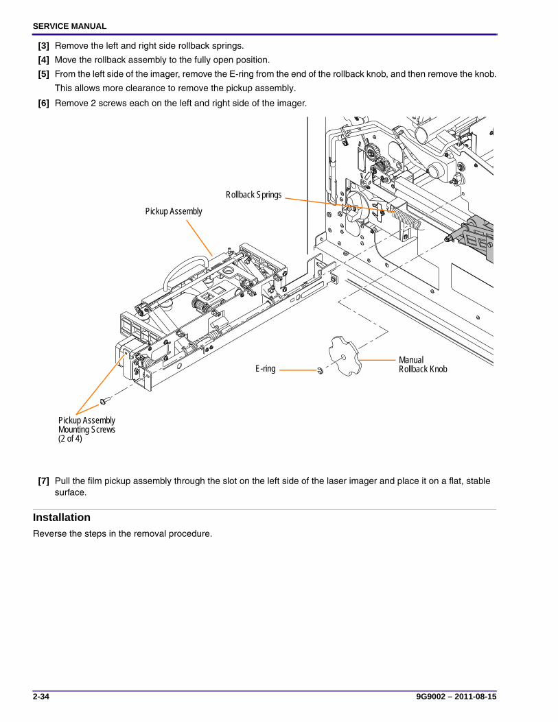
[3] Remove the left and right side rollback springs.
[4] Move the rollback assembly to the fully open position.
[5] From the left side of the imager, remove the E-ring from the end of the rollback knob, and then remove the knob.
This allows more clearance to remove the pickup assembly.
[6] Remove 2 screws each on the left and right side of the imager.
[7] Pull the film pickup assembly through the slot on the left side of the laser imager and place it on a flat, stable surface.
InstallationReverse the steps in the removal procedure.
Pickup Assembly Mounting Screws (2 of 4)
E-ring
Pickup Assembly
Manual Rollback Knob
Rollback Springs

Adjustments and Replacements
9G9002 – 2011-08-15 2-35
Suction Cup
RemovalPull the suction cup straight from the shaft.
InstallationPush the cup onto the shaft until it is fully seated.
Prerequisites: Remove the pickup assembly.
H221_6016GC
Suction Cup
Shaft

SERVICE MANUAL
2-36 9G9002 – 2011-08-15
Pickup Home Sensor
Removal
[1] Turn the motor gear to extend the pickup assembly to full length.
[2] Disconnect the connector.
[3] Remove the:
(a) Screw
(b) Pickup home sensor
InstallationReverse the steps in the removal procedure.
Prerequisites: Remove the pickup assembly.
Tools: T10 Torx driver
Motor Gear
Pickup Home Sensor
Screw

Adjustments and Replacements
9G9002 – 2011-08-15 2-37
Film Contact Sensor
Removal
[1] Disconnect the connector.
[2] Remove the:
(a) Screw
(b) Film contact sensor
InstallationReverse the steps in the removal procedure.
Prerequisites: Remove the pickup assembly.
Tools: T10 Torx driver
Film Contact Sensor

SERVICE MANUAL
2-38 9G9002 – 2011-08-15
Imaging Assembly
Removal[1] Remove 6 connectors from the MCS board:
• 4 across the bottom of the board (J19, J20, J21, J22)
• 2 on the right side of the board (J15, J17)
[2] Remove 2 screws on the right of the MCS board bracket.
Prerequisites: • Close the film cartridge. (Touch the Pause button on the display screen.)
• De-energize the laser imager.
• Disconnect the power cord.
• Remove:
– Top cover
– Right cover
– Left cover
• To support the imaging assembly during the procedure, move the front and rear shipping brackets into their shipping location (see Installation Instructions, “Moving the Shipping Brackets”). Use at least 2 screws per bracket.
Tools: T20 Torx driver
Connectors
Screws

Adjustments and Replacements
9G9002 – 2011-08-15 2-39
[3] Swing the MCS board open.
[4] Pull the 2 connectors in through the hole in the frame.
[5] Remove the 4 screws that secure the imaging assembly:
• 2 screws from the front guide rail
• 2 screws from the rear guide rail
[6] Carefully remove the imaging assembly and place it on a flat, stable surface.
Installation
ImportantYou must make a calibration print after installing the new imaging assembly.
[1] Reverse the steps in the removal procedure.
[2] Move the shipping brackets back to the operational position.
[3] Print a calibration image.
[4] Check the Start of Page and Index Delay settings.
Hole for Connectors
Screws (2 of 4)
Screws (2 of 4)
Imaging Assembly
MCS Board

SERVICE MANUAL
2-40 9G9002 – 2011-08-15
Optics and Exposure Transport
Removal[1] Remove 2 screws on each side of the imaging assembly where the optics and exposure transport are joined.
[2] Carefully separate the optics from the transport.
InstallationReverse the steps in the removal procedure.
NoteUse the alignment pins near the screw holes to help line up the two components.
Prerequisites: Remove the imaging assembly.
Tools: T20 Torx driver
Screws
Screws
Exposure Transport
Optics

Adjustments and Replacements
9G9002 – 2011-08-15 2-41
Exposure Transport Belt
Removal[1] Remove the:
(a) 5 cover screws
(b) Exposure transport cover
[2] Push down on the tensioner to release pressure on the belt.
[3] Slide the belt off the lower shaft and remove the belt.
InstallationReverse the steps in the removal procedure.
Prerequisites: Remove the:• Top cover
• Right cover
Tools: T10 Torx driver
Cover Screws
Cover Screws
Tensioner
Shaft
Belt

SERVICE MANUAL
2-42 9G9002 – 2011-08-15
Exposure Transport Motor
Removal[1] Disconnect the connector from the motor.
NoteThe connector position is tight. If necessary, use a small flathead screwdriver to remove the connector.
[2] Remove the:
(a) 4 screws
(b) Exposure transport motor
InstallationReverse the steps in the removal procedure.
Prerequisites: Remove the:• Imaging assembly
• Exposure transport belt
Tools: • T10 Torx driver
• Small flathead screwdriver (optional)
Connector terminal
Motor Screw (1 of 4)
Exposure Transport Motor
Adjustments and Replacements
9G9002 – 2011-08-15 2-43
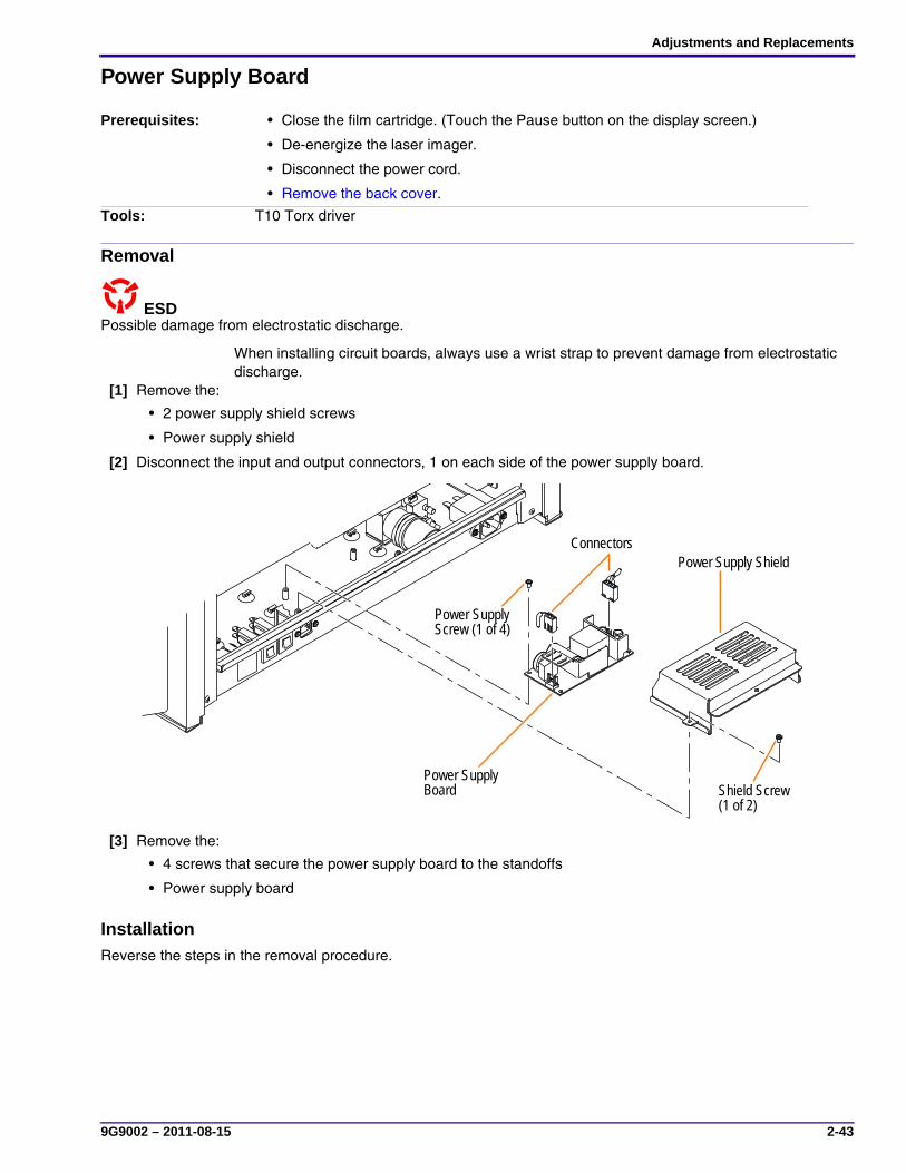
Power Supply Board
Removal
Possible damage from electrostatic discharge.ESD
When installing circuit boards, always use a wrist strap to prevent damage from electrostatic discharge.
[1] Remove the:
• 2 power supply shield screws
• Power supply shield
[2] Disconnect the input and output connectors, 1 on each side of the power supply board.
[3] Remove the:
• 4 screws that secure the power supply board to the standoffs
• Power supply board
InstallationReverse the steps in the removal procedure.
Prerequisites: • Close the film cartridge. (Touch the Pause button on the display screen.)
• De-energize the laser imager.
• Disconnect the power cord.
• Remove the back cover.
Tools: T10 Torx driver
H221_6021BC
Shield Screw (1 of 2)
Power Supply ShieldConnectors
Power Supply Screw (1 of 4)
Power Supply Board

SERVICE MANUAL
2-44 9G9002 – 2011-08-15
Machine Control System (MCS) Board
Removal
Possible damage from electrostatic discharge.ESD
When installing circuit boards, always use a wrist strap to prevent damage from electrostatic discharge.
[1] Disconnect all connectors.
[2] Remove:
• 6 screws
• Machine Control System (MCS) board
InstallationReverse the steps in the removal procedure.
NoteIf necessary, perform “Restoring the Configuration”.
Prerequisites: • Perform “Making a Configuration Backup”.
• Close the film cartridge. (Touch the Pause button on the display screen.)
• De-energize the laser imager.
• Disconnect the power cord.
• Remove the:
– Top cover
– Right cover
Tools: T10 Torx driver
Connectors
Screws

Adjustments and Replacements
9G9002 – 2011-08-15 2-45
DRE Motherboard Bracket
Removal
Possible damage from electrostatic discharge.ESD
When installing circuit boards, always use a wrist strap to prevent damage from electrostatic discharge.
[1] Remove the 5 tie wraps that hold the cables in place near the DRE motherboard bracket.
[2] Disconnect the connector and 3 network cables from the DRE motherboard.
Prerequisites: • Close the film cartridge. (Touch the Pause button on the display screen.)
• De-energize the laser imager.
• Disconnect the power cord.
• Remove the back cover.
Tools: 7 mm nut driver
Tie Wraps
Connector
Tie Wraps

SERVICE MANUAL
2-46 9G9002 – 2011-08-15
[3] Remove:
• 4 nuts
• Bracket with DRE motherboard
InstallationReverse the steps in the removal procedure.
NoteIf necessary, perform “Restoring the Configuration”.
Nut (1 of 4)
Bracket with DRE motherboard
Adjustments and Replacements
9G9002 – 2011-08-15 2-47
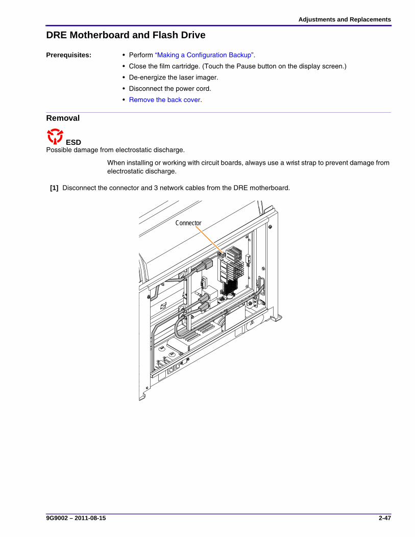
DRE Motherboard and Flash Drive
Removal
Possible damage from electrostatic discharge.ESD
When installing or working with circuit boards, always use a wrist strap to prevent damage from electrostatic discharge.
[1] Disconnect the connector and 3 network cables from the DRE motherboard.
Prerequisites: • Perform “Making a Configuration Backup”.
• Close the film cartridge. (Touch the Pause button on the display screen.)
• De-energize the laser imager.
• Disconnect the power cord.
• Remove the back cover.
Connector

SERVICE MANUAL
2-48 9G9002 – 2011-08-15
[2] Remove the:
(a) 4 screws that mount the DRE motherboard to the bracket.
(b) DRE motherboard from the bracket.
(c) If you are replacing the motherboard, remove the USB keylock to install on the new motherboard.
[3] Slide the flash drive out from the port on the back of the DRE motherboard.
Screws (3 of 4)
DRE Motherboard
Screw (1 of 4)
BracketUSB Keylock
Back of DRE Motherboard
Flash Drive

Adjustments and Replacements
9G9002 – 2011-08-15 2-49
Installation
ImportantIf replacing the motherboard, remove the USB keylock from the old motherboard and install it on the new motherboard.
[1] Reverse the steps of the removal procedure.
[2] Energize the imager.
[3] After the system is operational, perform “Restoring the Configuration”.

SERVICE MANUAL
2-50 9G9002 – 2011-08-15
This page is intentionally blank.
Preventive Maintenance
9G9002 – 2011-08-15 3-1
Section 3: Preventive Maintenance
Necessary MaterialsThe materials necessary for performing Preventive Maintenance (PM) are:
• Tools
• PM materials
Required Tools
• Laptop computer with MICROSOFT WINDOWS 98 operating system or higher and MICROSOFT INTERNET EXPLORER
• Service tool
• Crossover cable
• Temperature meter with probe
• Block for probe, kit
• Vacuum cleaner
• Flashlight
• Scraper – recommended blade size is 1.25 × 4.75 in.
• T20 Torx driver
• T10 Torx driver
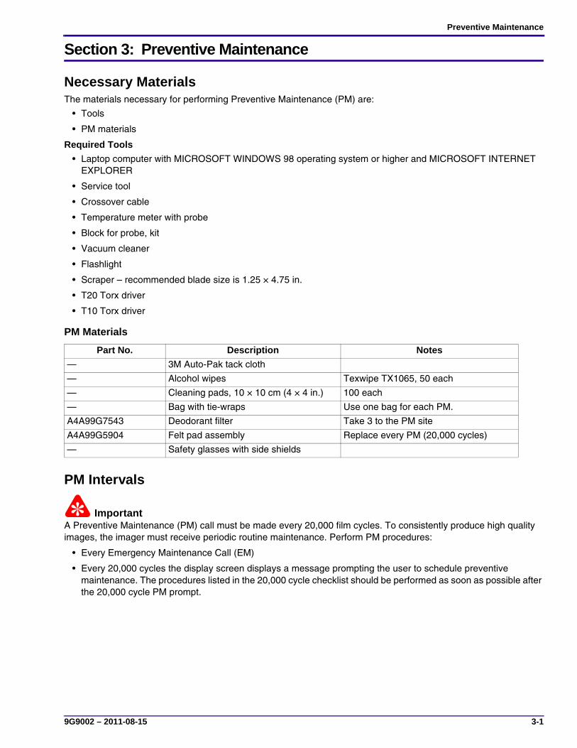
PM Materials
PM Intervals
ImportantA Preventive Maintenance (PM) call must be made every 20,000 film cycles. To consistently produce high quality images, the imager must receive periodic routine maintenance. Perform PM procedures:
• Every Emergency Maintenance Call (EM)
• Every 20,000 cycles the display screen displays a message prompting the user to schedule preventive maintenance. The procedures listed in the 20,000 cycle checklist should be performed as soon as possible after the 20,000 cycle PM prompt.
Part No. Description Notes
— 3M Auto-Pak tack cloth
— Alcohol wipes Texwipe TX1065, 50 each
— Cleaning pads, 10 × 10 cm (4 × 4 in.) 100 each
— Bag with tie-wraps Use one bag for each PM.
A4A99G7543 Deodorant filter Take 3 to the PM site
A4A99G5904 Felt pad assembly Replace every PM (20,000 cycles)
— Safety glasses with side shields
SERVICE MANUAL
3-2 9G9002 – 2011-08-15
Modifications
ImportantCheck the modification status of the imager at each PM call. If any Type 1 modifications are outstanding, install them during the call. It is important to fit modifications promptly at scheduled maintenance times to improve and maintain imager performance to corporate and customer expectations.
EM Call ChecklistIf the number of prints since the last PM is more than 18,500, use the 20,000 Cycle PM Procedure instead of the EM call checklist.
[1] Repair the print problem that caused the EM call.
[2] Touch the Pause icon on the display screen to close the film cartridge.
[3] De-energize the laser imager, and then disconnect the power cord.
[4] Remove the:
• Top cover
• Left cover (see Adjustments and Replacements, “Left cover”).
• Right cover (see Adjustments and Replacements, “Right Cover”).
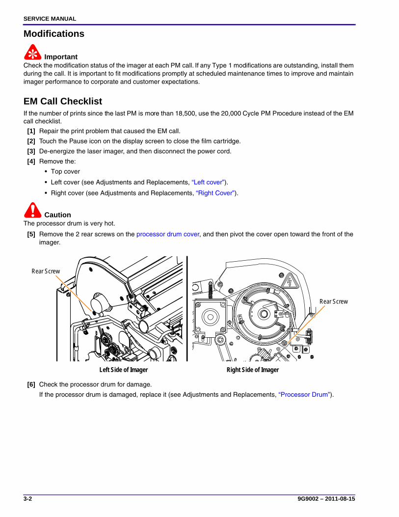
CautionThe processor drum is very hot.
[5] Remove the 2 rear screws on the processor drum cover, and then pivot the cover open toward the front of the imager.
[6] Check the processor drum for damage.
If the processor drum is damaged, replace it (see Adjustments and Replacements, “Processor Drum”).
Rear Screw
Left Side of Imager Right Side of Imager
Rear Screw

Preventive Maintenance
9G9002 – 2011-08-15 3-3
CautionIsopropyl alcohol is highly flammable. Follow the manufacturer’s instructions for safe use and handling.
[7] Use alcohol wipes to clean the processor drum and processor cover rollers.
NoteAfter cleaning, place the used wipes in a bag, close the bag with a tie-wrap, and dispose of it according to local ordinances.
[8] If you installed a new processor drum, calibrate the processor drum temperature (see Adjustments and Replacements, “Processor—Drum Temperature Adjustment”).
Processor Cover Rollers
Processor Drum

SERVICE MANUAL
3-4 9G9002 – 2011-08-15
Performing the PMEvery PM, perform all of the following procedures in the order listed:
[1] Print a flat-field gray film to compare against the film after PM is complete.
(a) In the service tool, select Diagnostics > DRE > Advanced Test Print.
(b) In the Test Profile drop-down list, select Flat1.8.
(c) Click Run.
[2] Touch the Pause icon on the display screen to close the film cartridge.
[3] Open the film supply and remove the film cartridge. Leave the film supply open.
[4] De-energize the imager, and then disconnect the power cord.
[5] Remove the:
• Top cover (see Adjustments and Replacements, “Top Cover”).
• Left cover (see Adjustments and Replacements, “Left cover”).
• Right cover (see Adjustments and Replacements, “Right Cover”).
CautionThe processor drum is very hot. Allow it to cool for 10 minutes before cleaning.
[6] Pivot open the processor drum cover.
Continue with the next steps while the processor drum cools.
[7] Remove the deodorant filter.
[8] Use a vacuum cleaner to clean the:
• Deodorant filter area
• Filter duct
• Exhaust plenum

Preventive Maintenance
9G9002 – 2011-08-15 3-5
[9] On the left side of the imager, vacuum the:
• Processor drum exhaust port
• Filter duct
[10] Vacuum the 2 exhaust holes on the left cover.
H221_6024HC
Deodorant Filter area
Exhaust Plenum Filter Duct
Processor Drum Exhaust Port
Filter Duct
Exhaust Holes

SERVICE MANUAL
3-6 9G9002 – 2011-08-15
[11] Take a sheet of the largest size film available and cut it lengthwise to make a strip 8 cm (3 in.) wide.
NoteThe strip is used to cover and protect the imaging assembly from debris during cleaning.
[12] Fold the film strip lengthwise to form a V.
[13] From the left side of the imager, insert the strip over the imaging roller to cover it.
[14] Clean the processor drum.
• Wipe the processor drum with alcohol wipes in one direction with an even steady pressure. Rotate the processor drum while wiping.
• Check the processor drum for imperfections, gouges, and areas of excessive buildup of debris.
[15] Clean and inspect the processor cover rollers.
[16] Pivot the processor drum cover closed.
[17] Pivot the heat shield open.
[18] Remove the felt pad assembly from the diverter assembly (see Adjustments and Replacements, “Felt Pad Assembly”).
Folded Strip of Film
Preventive Maintenance
9G9002 – 2011-08-15 3-7
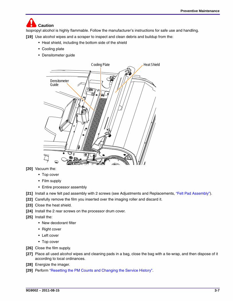
CautionIsopropyl alcohol is highly flammable. Follow the manufacturer’s instructions for safe use and handling.
[19] Use alcohol wipes and a scraper to inspect and clean debris and buildup from the:
• Heat shield, including the bottom side of the shield
• Cooling plate
• Densitometer guide
[20] Vacuum the:
• Top cover
• Film supply
• Entire processor assembly
[21] Install a new felt pad assembly with 2 screws (see Adjustments and Replacements, “Felt Pad Assembly”).
[22] Carefully remove the film you inserted over the imaging roller and discard it.
[23] Close the heat shield.
[24] Install the 2 rear screws on the processor drum cover.
[25] Install the:
• New deodorant filter
• Right cover
• Left cover
• Top cover
[26] Close the film supply.
[27] Place all used alcohol wipes and cleaning pads in a bag, close the bag with a tie-wrap, and then dispose of it according to local ordinances.
[28] Energize the imager.
[29] Perform “Resetting the PM Counts and Changing the Service History”.
Heat ShieldCooling Plate
Densitometer Guide

SERVICE MANUAL
3-8 9G9002 – 2011-08-15
Resetting the PM Counts and Changing the Service History[1] In the service tool, select Monitoring and Control > Imager Monitor.
The Imager Monitor screen displays.
[2] Click:
• Reset Prints To PM
This action also enters the PM record into the service history.
• Reset Prints To Filter Replacement
[3] Perform “Completing the PM”.
Completing the PM[1] Wait while the processor warms to Ready.
[2] Check the temperature of the drum (see Adjustments and Replacements, “Processor—Drum Temperature Adjustment”).
[3] If necessary, adjust the temperature.
[4] Make a flat-field gray test print.
[5] Compare the test print with the test print made before the PM.
[6] Make a print of a customer image.
[7] Check the quality of the print with the customer.
[8] Leave 2 deodorant filters with the customer.

Diagnostics
9G9002 – 2011-08-15 4-1
Section 4: Diagnostics
Using the Service SwitchThe service switch is located behind the right cover at the top right corner of the MCS board.
[1] Touch the Pause icon on the display screen to close the film cartridge.
[2] De-energize the laser imager, and then disconnect the power cord.
[3] Remove the:
• Top cover (see Adjustments and Replacements, “Top Cover”).
• Right cover (see Adjustments and Replacements, “Right Cover”).
[4] To activate the service switch, push the button down to SERV.
[5] To deactivate the service switch, push the button up to NORMAL.
The Service Mode icon disappears from the display screen.
Service Switch

SERVICE MANUAL
4-2 9G9002 – 2011-08-15
Display Screen Symbols
1 Error code. When lit, this code displays an applicable code for the error, such as film jam, restart error condition, or filter change is needed.
2 Film Size/Queue symbol. When lit, this symbol indicates the status of media in the image, such as requested media is not loaded.
3 Restart symbol. Indicates an error condition. It requires that you power the laser imager on/off.
4 Calibration symbol. When lit, this symbol indicates that a calibration is in process.5 Status/Ready symbol. Indicates that the laser imager is ready to print or, if it is blinking, that
the laser imager is warming up.6 Film Size/Count code. This code changes to indicate the film size loaded and the film count
left in the cartridge. If zero, it indicates an empty film cartridge.7 Wrench symbol. Indicates that a filter change or preventive maintenance is needed.8 Film Jam symbol. Indicates that a film jam occurred.9 Pause symbol. When blinking, the film cartridge cover is open.
1 2 3 4
6 7 8 9
5

Diagnostics
9G9002 – 2011-08-15 4-3
Display Screen Symbols—Detailed Descriptions
Symbol Description
Power• When steady green, the laser imager is ready to print.
• When blinking green, the laser imager is processing or printing.
• When steady yellow, attention is needed.
Refer to other symbol descriptions for details.
• When blinking yellow, the laser imager is warming up.
The screen also displays the time-until-ready countdown.
Error or Status Code• A 3-digit code displays when an error or status condition is present.
If the laser imager is on and a 3-digit code does not display, the imager is operating normally.
• A 2-digit code displays the requested film size if the loaded film size does not match the requested size.
The code alternates between the height and width of the requested size.
Film Count and Dimensions• Displays the number of films remaining in the film cartridge or the loaded film size
• Displays the height and width of the loaded film size
Calibrate • When steady blue, press this symbol to initiate calibration.
• When blinking blue, calibration is in process.
• When yellow, calibration failed or a calibration error occurred.
Pause• During normal operation, this symbol is off.
• When the film cartridge cover is open, this symbol is on.
– You can press the symbol to close the film cartridge cover.
– To avoid exposing the film to light, do not open the film supply until the symbol is off.
Film Size• When this symbol is on, the wrong film size is loaded for the requested print job. The
Status Code display shows the requested film size.
• You can press and hold the symbol for five seconds to delete all print requests.
RestartYou must restart the laser imager. An error code also displays to indicate why the restart is required.
Film JamFilm is jammed. An error code also displays to indicate the location of the jam.
MaintenancePreventive maintenance is required. An error code also displays to indicate the required action.
SERVICE MANUAL
4-4 9G9002 – 2011-08-15
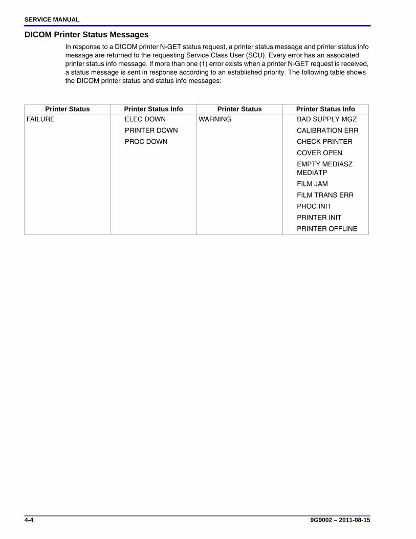
DICOM Printer Status MessagesIn response to a DICOM printer N-GET status request, a printer status message and printer status info message are returned to the requesting Service Class User (SCU). Every error has an associated printer status info message. If more than one (1) error exists when a printer N-GET request is received, a status message is sent in response according to an established priority. The following table shows the DICOM printer status and status info messages:
Printer Status Printer Status Info Printer Status Printer Status Info
FAILURE ELEC DOWN
PRINTER DOWN
PROC DOWN
WARNING BAD SUPPLY MGZ
CALIBRATION ERR
CHECK PRINTER
COVER OPEN
EMPTY MEDIASZ MEDIATP
FILM JAM
FILM TRANS ERR
PROC INIT
PRINTER INIT
PRINTER OFFLINE

Diagnostics
9G9002 – 2011-08-15 4-5
Machine Control System (MCS) Imager Status MessagesThe following table describes how the display screen and Web Portal indicate imager status to the user:
Printer Status Display Screen
Web Portal (remote) Display DICOM Status Description
Service Mode Service Mode WARNING / PRINTER OFFLINE
The service override switch is enabled. The laser imager is not ready.
Offline Printing Disabled
WARNING / PRINTER OFFLINE
Printing/delivery has been disabled.
Failed
(Code will vary)
Failed See error tables An error occurred that prevents printing.
Self-test Self-test WARNING /PRINTER INIT
This occurs when power is first applied to the MCS.
Warming up Warming=xx WARNING / PROC INIT
The processor is currently warming up and will not be ready to print for xx minutes.
Door Open Cover Open WARNING / COVER OPEN
A laser imager cover is open. Laser imager not ready. (A side cover could be off.)
Printing Printing NORMAL The laser imager is printing.
Ready Ready NORMAL The laser imager is online and the processor has reached operating temperature.
Pause (cartridge close requested)
Not Ready WARNING / COVER OPEN
The laser imager is completing prints in progress.
SERVICE MANUAL
4-6 9G9002 – 2011-08-15
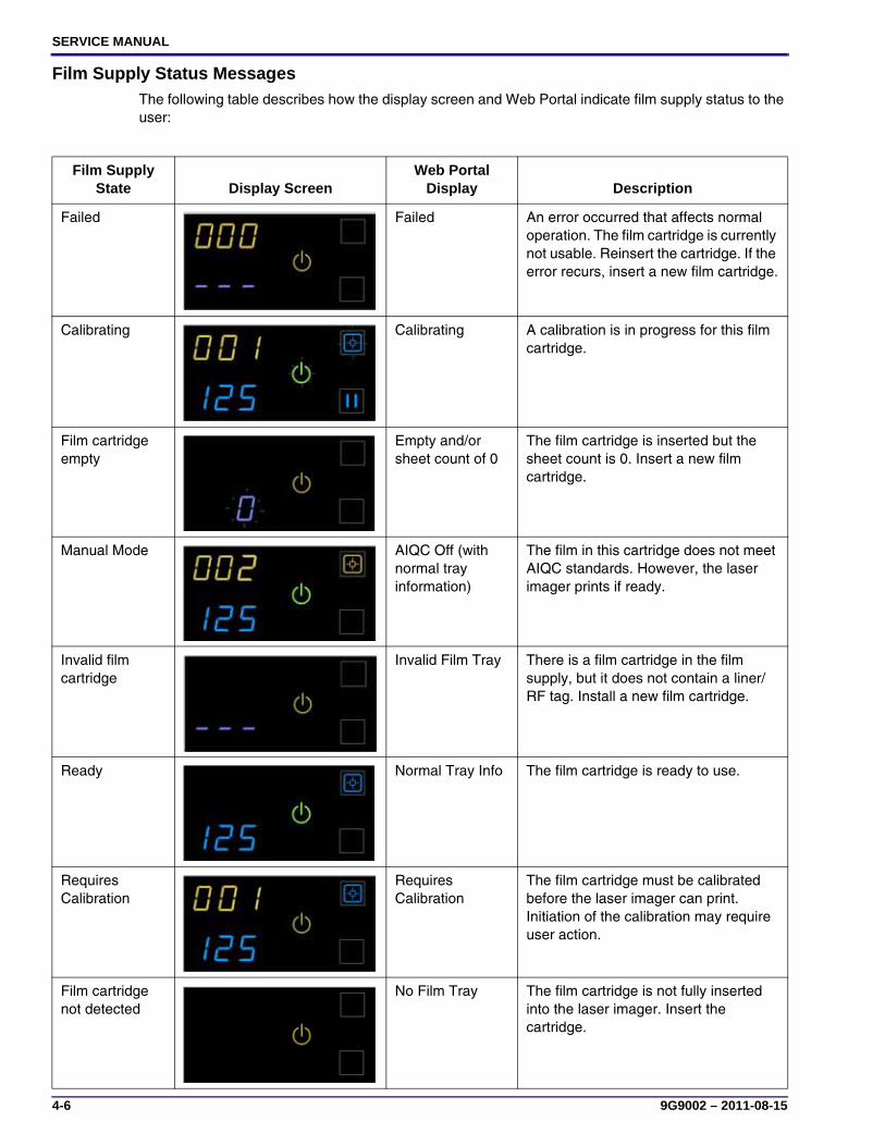
Film Supply Status MessagesThe following table describes how the display screen and Web Portal indicate film supply status to the user:
Film Supply State Display Screen
Web Portal Display Description
Failed Failed An error occurred that affects normal operation. The film cartridge is currently not usable. Reinsert the cartridge. If the error recurs, insert a new film cartridge.
Calibrating Calibrating A calibration is in progress for this film cartridge.
Film cartridge empty
Empty and/or sheet count of 0
The film cartridge is inserted but the sheet count is 0. Insert a new film cartridge.
Manual Mode AIQC Off (with normal tray information)
The film in this cartridge does not meet AIQC standards. However, the laser imager prints if ready.
Invalid film cartridge
Invalid Film Tray There is a film cartridge in the film supply, but it does not contain a liner/RF tag. Install a new film cartridge.
Ready Normal Tray Info The film cartridge is ready to use.
Requires Calibration
Requires Calibration
The film cartridge must be calibrated before the laser imager can print. Initiation of the calibration may require user action.
Film cartridge not detected
No Film Tray The film cartridge is not fully inserted into the laser imager. Insert the cartridge.

Diagnostics
9G9002 – 2011-08-15 4-7
Job Manager Status MessagesThe following table describes how the display screen and Web Portal indicate job status to the user:
Not Ready Varies Not Ready When the conditions are corrected, the laser imager can print.
Cartridge closure pending
Pause Requested
You pressed the Pause button, but the film cartridge has not started to close because films are still moving through the imager. When the cartridge finishes closing, the Pause symbol turns off and you can remove the film cartridge.
Job Manager Status Display Screen Web Portal Display Description
Active Not applicable Shows how many jobs having this status are queued
The laser imager is accepting DICOM job requests and film is available for all current jobs.
No Media
(Status Code shows requested size)
Shows how many jobs having this status are queued
The laser imager is accepting DICOM job requests, but film of the correct size and type is not available for at least one current job.
Offline DICOM Offline The laser imager cannot accept any DICOM job requests. Restart the imager.
Film Supply State Display Screen
Web Portal Display Description

SERVICE MANUAL
4-8 9G9002 – 2011-08-15
Condition Codes
Subsystems in the laser imager
NoteEach subsystem has a range of error numbers. The numbers have two parts, a subsystem ID number and an error ID number. This number system keeps the error ID numbers given to software components in other laser imagers for similar errors. The subsystem ID and error number are only separated by a hyphen on the Web Portal and not on the display screen or in the error log. For example, the Web Portal displays “20-209” while the error log displays “20209.”
Subsystem IDs
Subsystem ID Subsystem/Component Name Error IDMIM Core Components:
01 Configuration and Control Subsystem 01-xxx04 DICOM Input Print Service SCP Subsystem 04-xxx05 Study Reclamation Subsystem 05-xxx06 Delivery Subsystem 06-xxx
DRE:10 Delivery Subsystem (also contains certain system-wide
definitions)10-xxx
13–14 Service tool or Web Portal User Interface 13-xxx, 14-xxx
MCS:20 General MCS System 20-xxx21 Film Supply Drawer 21-xxx25 RF Tag 25-xxx26 Film Transport (jams and film path controller errors) 26-xxx27 Optics (beam power micro and FPGA) 27-xxx28 Processor 28-xxx29 Densitometer 29-xxx36 Display Screen 36-xxx

Diagnostics
9G9002 – 2011-08-15 4-9
Severity Levels
The following table describes the severity levels associated with condition codes for the laser imager:
Severity Description Example
Display Screen Notify
(Notes 1 and 2)
Web Portal Notify
(Notes 1 and 2) Recovery
0=Fatal A failure occurred and the laser imager will have to be restarted.
• System resource failure
• Hardware failures for unique subsystems
• Configuration/registry failure
• Software init failure
• Network unavailable
Yes Yes The laser imager must be restarted.
1=Alert A failure occurred, but it should be temporary and correctable by the user.
Film jam Yes Yes The laser imager should be able to continue after the problem is corrected. If the failure is film supply specific, the laser imager should be able to continue operating using the other film supply.
2=Warning An event occurred that should notify the user.
Connection lost (SCU to SCP) Yes Yes No recovery needed.
3=Notify An event occurred, but was automatically recovered.
• Communication retries
• Film pickup retry
• Approaching warning sidebands or limits of adjustment
No No A notice is written to the log. The laser imager should be able to continue automatically.
4=Auxiliary Status information • Indicate status of a supply cartridge, such as film saver on, or manual mode
• Indicate status of the laser imager, such as cover open, or film cartridge missing
Yes No Does not impact laser imager operation.
Note 1: This table describes general behavior—there are exceptions to these generalizations, predominantly in the MIM Core Conditions Section. See the individual errors for specific information about Web Portal and Display Screen notification and alarms.
Note 2: The display screen is limited to very simple communication scheme (codes and lights), and so it makes use of the auxiliary codes; the Web Portal's more sophisticated user interface does not require auxiliary codes in order to detect and communicate the same conditions.

SERVICE MANUAL
4-10 9G9002 – 2011-08-15
Condition Code: 01-000 – General Configuration and Control Subsystem Error
Condition Code: 01-001 – Maximum Number of Allowed Restarts for a Subsystem or Component Has Been Exceeded
Web Portal Message Log MessageDICOM Printer
StatusInfo Severity
None General Error in Configuration and Control Subsystem
NORMAL 3-Notify
Description A general error occurred in the Configuration and Control Subsystem.
System Impact Unknown. This is an unexpected or unknown error; it is not possible to document specific details.
User Action None
Show at DS False
DICOM Printer Status
NORMAL
Unique Symb. ID ERR_CONFIG_CONTROL
Web Portal Message Log MessageDICOM Printer
StatusInfo Severity
None Maximum Number of Restarts Exceeded for xxxx (where xxxx is the subsystem name)
NORMAL 2-Warning
Description When a subsystem or component generates a non-recoverable, Configuration-and-Control will attempt to shut down and restart it. This error means that Configuration-and-Control has initiated more than the configured number of allowed restarts.
System Impact The system will continue to run normally, unless the subsystem or component in question cannot run any longer.
User Action None
DICOM Printer Status
NORMAL
Unique Symb. ID ERR_EXCEED_MAX_RESTARTS
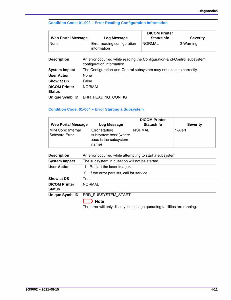
Diagnostics
9G9002 – 2011-08-15 4-11
Condition Code: 01-002 – Error Reading Configuration Information
Condition Code: 01-004 – Error Starting a Subsystem
Web Portal Message Log MessageDICOM Printer
StatusInfo Severity
None Error reading configuration information
NORMAL 2-Warning
Description An error occurred while reading the Configuration-and-Control subsystem configuration information.
System Impact The Configuration-and-Control subsystem may not execute correctly.
User Action None
Show at DS False
DICOM Printer Status
NORMAL
Unique Symb. ID ERR_READING_CONFIG
Web Portal Message Log MessageDICOM Printer
StatusInfo Severity
MIM Core: Internal Software Error
Error starting subsystem xxxx (where xxxx is the subsystem name)
NORMAL 1-Alert
Description An error occurred while attempting to start a subsystem.
System Impact The subsystem in question will not be started.
User Action 1. Restart the laser imager.
2. If the error persists, call for service.
Show at DS True
DICOM Printer Status
NORMAL
Unique Symb. ID ERR_SUBSYSTEM_START
NoteThe error will only display if message queueing facilities are running.

SERVICE MANUAL
4-12 9G9002 – 2011-08-15
Condition Code: 01-005 – Error Stopping a Subsystem
Condition Code: 01-007 – General Subsystem Communication Error
Web Portal Message Log MessageDICOM Printer
StatusInfo Severity
None Error stopping subsystem xxxx (where xxxx is the subsystem name)
NORMAL 1-Alert
Description An error occurred while attempting to stop a subsystem.
System Impact The subsystem in question may still be running, in which case full shutdown will not be possible.
User Action None
Show at DS False
DICOM Printer Status
NORMAL
Unique Symb. ID ERR_SUBSYSTEM_STOP
NoteRationale for not reporting to user: The user requests shutdown of the entire laser imager, not just a subsystem. The OS will eventually shut down regardless of whether all subsystems shut down successfully.
Web Portal Message Log MessageDICOM Printer
StatusInfo Severity
None Configuration and Control Subsystem cannot communicate with subsystem xxxx (where xxxx is the subsystem name)
NORMAL 2-Warning
Description An unknown error occurred while communicating with a subsystem.
System Impact Configuration-and-Control will attempt to re-establish communications with the subsystem in question. If communication is lost, the subsystem will be shut down by force and restarted.
User Action None
Show at DS False
DICOM Printer Status
NORMAL
Unique Symb. ID ERR_SUBSYSTEM_COM

Diagnostics
9G9002 – 2011-08-15 4-13
Condition Code: 01-008 – All Subsystems Have Been Started
Condition Code: 01-009 – Operating System Could Not Be Shut Down
Web Portal Message Log MessageDICOM Printer
StatusInfo Severity
None All subsystems successfully started
NORMAL 3-Notify
Description All subsystems to be started by the Configuration-and-Control subsystem have been started.
NoteThis code will not be sent as a message.
System Impact None. The system will function normally. [SI-0]
User Action None
Show at DS False
DICOM Printer Status
NORMAL
Unique Symb. ID ERR_ALL_START_COM
Web Portal Message Log MessageDICOM Printer
StatusInfo Severity
None OS could not be shut down
NORMAL 3-Notify
Description The operating system did not complete the shutdown in the expected amount of time.
NoteThis code will not be sent as a message.
System Impact None. The system will function normally. [SI-0]
User Action None
Show at DS False
DICOM Printer Status
NORMAL
Unique Symb. ID ERR_NO_OS_SHUTDOWN

SERVICE MANUAL
4-14 9G9002 – 2011-08-15
Condition Code: 01-010 – A Subsystem Terminated Abnormally
Condition Code: 04-000 – General DICOM Input Print SCP Subsystem Error
Web Portal Message Log MessageDICOM Printer
StatusInfo Severity
None Subsystem xxxx terminated (where xxxx is the system name)
NORMAL 3-Notify
Description A subsystem that was started by the Configuration-and-Control subsystem terminated abnormally.
NoteThis code will not be sent as a message.
System Impact The subsystem will be temporarily unavailable until it is restarted by the Configuration-and-Control subsystem. Depending on the subsystem, it may cause associations to be rejected or printing to be delayed.
User Action None
Show at DS False
DICOM Printer Status
NORMAL
Unique Symb. ID ERR_ABNORMAL_TERMINATION
Web Portal Message Log MessageDICOM Printer
StatusInfo Severity
None General Error in DICOM Input Print SCP Subsystem
NORMAL 3-Notify
Description A general error occurred in the DICOM Input Print Service Class Provider (SCP) Subsystem.
System Impact Unknown. This is an unexpected or unknown error; it is not possible to document specific details.
User Action None
Show at DS False
DICOM Printer Status
NORMAL
Unique Symb. ID ERR_GEN_DICOM

Diagnostics
9G9002 – 2011-08-15 4-15
Condition Code: 04-100 – Limit on Number of Simultaneous Associations
Condition Code: 04-101 – The Called AE Title Does Not Correspond to a Recognized Printer
Web Portal Message Log MessageDICOM Printer
StatusInfo Severity
None Maximum Number of Associations Exceeded
NORMAL 1-Alert
Description The maximum number of associations configured has been exceeded. The association is rejected.
System Impact The Service Class User (SCU) will not be able to open an association, and therefore will not be able to deliver a print job.
User Action None
Show at DS False
DICOM Printer Status
NORMAL
Unique Symb. ID ERR_EXCEED_ASSOC
NoteRationale for not reporting to user: This problem is likely transient. If it is not, the user cannot correct this from the imager.
Additional DICOM information: There is a specific result/reason code available for this circumstance: -Rejected transient/3-Local limit exceeded.
Web Portal Message Log MessageDICOM Printer
StatusInfo Severity
None No Destination Matching Called AE Title
NORMAL 1-Alert
Description The AE title did not map to a destination that is currently available at this Service Class Provider (SCP).
System Impact The SCU will not be able to open an association, and therefore will not be able to deliver a print job.
User Action None
Show at DS False
DICOM Printer Status
NORMAL
Unique Symb. ID ERR_AE_NOT_RECOGNIZED
NoteRationale for not reporting to user: This is a DICOM SCU configuration problem, not an operational error. The user cannot correct this from the imager.
Additional DICOM information: There is a specific result/reason code available for this circumstance: 1-Rejected permanent/7-Called AE title not recognized.
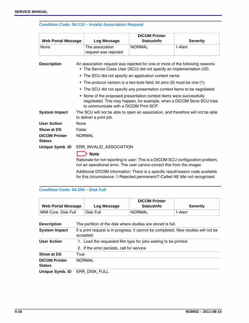
SERVICE MANUAL
4-16 9G9002 – 2011-08-15
Condition Code: 04-110 – Invalid Association Request
Condition Code: 04-200 – Disk Full
Web Portal Message Log MessageDICOM Printer
StatusInfo Severity
None The association request was rejected
NORMAL 1-Alert
Description An association request was rejected for one or more of the following reasons: • The Service Class User (SCU) did not specify an implementation UID.
• The SCU did not specify an application context name.
• The protocol version is a two-byte field; bit zero (0) must be one (1).
• The SCU did not specify any presentation context items to be negotiated.
• None of the proposed presentation context items were successfully negotiated. This may happen, for example, when a DICOM Store SCU tries to communicate with a DICOM Print SCP.
System Impact The SCU will not be able to open an association, and therefore will not be able to deliver a print job.
User Action None
Show at DS False
DICOM Printer Status
NORMAL
Unique Symb. ID ERR_INVALID_ASSOCIATION
NoteRationale for not reporting to user: This is a DICOM SCU configuration problem, not an operational error. The user cannot correct this from the imager.
Additional DICOM information: There is a specific result/reason code available for this circumstance: 1-Rejected permanent/7-Called AE title not recognized.
Web Portal Message Log MessageDICOM Printer
StatusInfo Severity
MIM Core: Disk Full Disk Full NORMAL 1-Alert
Description The partition of the disk where studies are stored is full.
System Impact If a print request is in progress, it cannot be completed. New studies will not be accepted.
User Action 1. Load the requested film type for jobs waiting to be printed.
2. If the error persists, call for service.
Show at DS True
DICOM Printer Status
NORMAL
Unique Symb. ID ERR_DISK_FULL
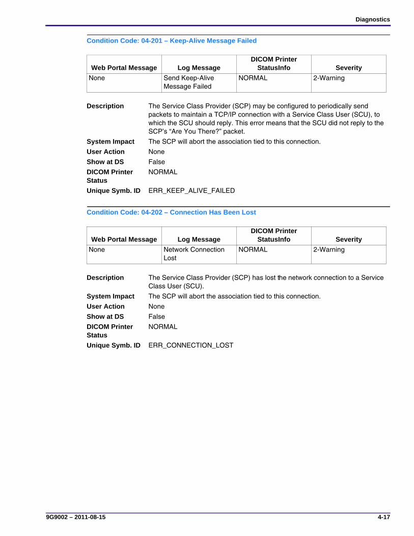
Diagnostics
9G9002 – 2011-08-15 4-17
Condition Code: 04-201 – Keep-Alive Message Failed
Condition Code: 04-202 – Connection Has Been Lost
Web Portal Message Log MessageDICOM Printer
StatusInfo Severity
None Send Keep-Alive Message Failed
NORMAL 2-Warning
Description The Service Class Provider (SCP) may be configured to periodically send packets to maintain a TCP/IP connection with a Service Class User (SCU), to which the SCU should reply. This error means that the SCU did not reply to the SCP’s “Are You There?” packet.
System Impact The SCP will abort the association tied to this connection.
User Action None
Show at DS False
DICOM Printer Status
NORMAL
Unique Symb. ID ERR_KEEP_ALIVE_FAILED
Web Portal Message Log MessageDICOM Printer
StatusInfo Severity
None Network Connection Lost
NORMAL 2-Warning
Description The Service Class Provider (SCP) has lost the network connection to a Service Class User (SCU).
System Impact The SCP will abort the association tied to this connection.
User Action None
Show at DS False
DICOM Printer Status
NORMAL
Unique Symb. ID ERR_CONNECTION_LOST
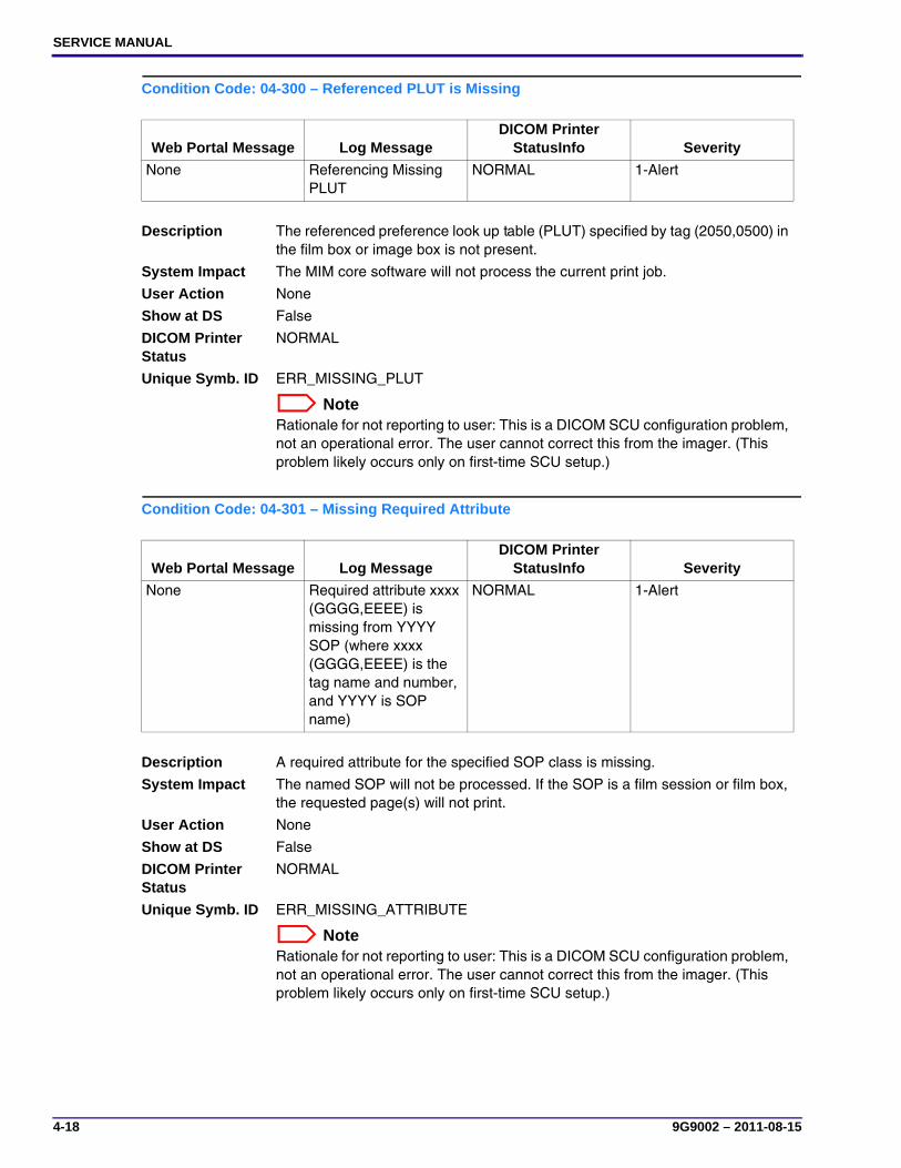
SERVICE MANUAL
4-18 9G9002 – 2011-08-15
Condition Code: 04-300 – Referenced PLUT is Missing
Condition Code: 04-301 – Missing Required Attribute
Web Portal Message Log MessageDICOM Printer
StatusInfo Severity
None Referencing Missing PLUT
NORMAL 1-Alert
Description The referenced preference look up table (PLUT) specified by tag (2050,0500) in the film box or image box is not present.
System Impact The MIM core software will not process the current print job.
User Action None
Show at DS False
DICOM Printer Status
NORMAL
Unique Symb. ID ERR_MISSING_PLUT
NoteRationale for not reporting to user: This is a DICOM SCU configuration problem, not an operational error. The user cannot correct this from the imager. (This problem likely occurs only on first-time SCU setup.)
Web Portal Message Log MessageDICOM Printer
StatusInfo Severity
None Required attribute xxxx (GGGG,EEEE) is missing from YYYY SOP (where xxxx (GGGG,EEEE) is the tag name and number, and YYYY is SOP name)
NORMAL 1-Alert
Description A required attribute for the specified SOP class is missing.
System Impact The named SOP will not be processed. If the SOP is a film session or film box, the requested page(s) will not print.
User Action None
Show at DS False
DICOM Printer Status
NORMAL
Unique Symb. ID ERR_MISSING_ATTRIBUTE
NoteRationale for not reporting to user: This is a DICOM SCU configuration problem, not an operational error. The user cannot correct this from the imager. (This problem likely occurs only on first-time SCU setup.)
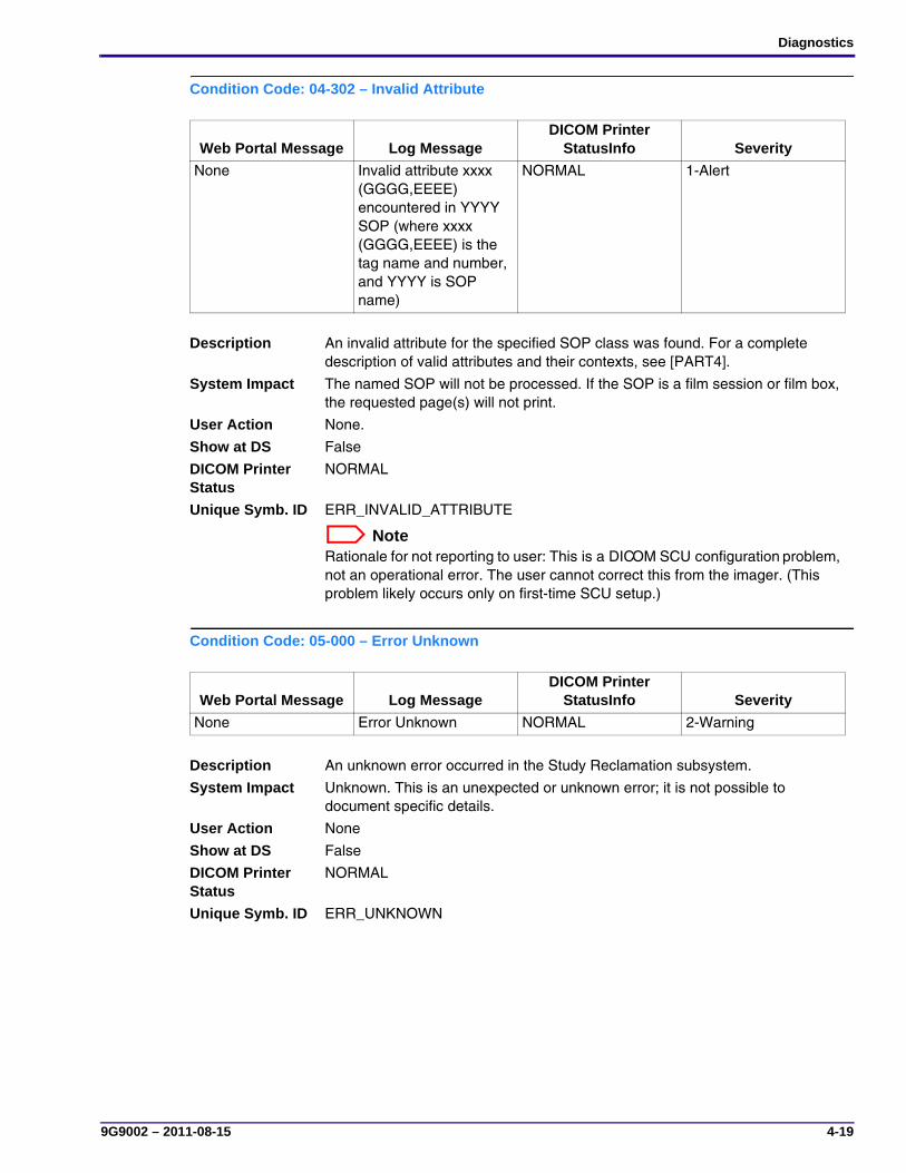
Diagnostics
9G9002 – 2011-08-15 4-19
Condition Code: 04-302 – Invalid Attribute
Condition Code: 05-000 – Error Unknown
Web Portal Message Log MessageDICOM Printer
StatusInfo Severity
None Invalid attribute xxxx (GGGG,EEEE) encountered in YYYY SOP (where xxxx (GGGG,EEEE) is the tag name and number, and YYYY is SOP name)
NORMAL 1-Alert
Description An invalid attribute for the specified SOP class was found. For a complete description of valid attributes and their contexts, see [PART4].
System Impact The named SOP will not be processed. If the SOP is a film session or film box, the requested page(s) will not print.
User Action None.
Show at DS False
DICOM Printer Status
NORMAL
Unique Symb. ID ERR_INVALID_ATTRIBUTE
NoteRationale for not reporting to user: This is a DICOM SCU configuration problem, not an operational error. The user cannot correct this from the imager. (This problem likely occurs only on first-time SCU setup.)
Web Portal Message Log MessageDICOM Printer
StatusInfo Severity
None Error Unknown NORMAL 2-Warning
Description An unknown error occurred in the Study Reclamation subsystem.
System Impact Unknown. This is an unexpected or unknown error; it is not possible to document specific details.
User Action None
Show at DS False
DICOM Printer Status
NORMAL
Unique Symb. ID ERR_UNKNOWN

SERVICE MANUAL
4-20 9G9002 – 2011-08-15
Condition Code: 05-001 – Error Reading Configuration Information
Condition Code: 05-002 – Study Reclamation Initiated
Web Portal Message Log MessageDICOM Printer
StatusInfo Severity
None Error reading configuration information
NORMAL 2-Warning
Description An error occurred while reading the Study Reclamation subsystem configuration information.
System Impact The Study Reclamation subsystem may not execute correctly.
User Action None
Show at DS False
DICOM Printer Status
NORMAL
Unique Symb. ID ERR_CONFIG_READ
Web Portal Message Log MessageDICOM Printer
StatusInfo Severity
None High water-mark reached. Scheduled study reclamation time reached.
NORMAL 3-Notify
Description Study reclamation has been initiated because either the “high-water mark” has been reached or the scheduled time for study reclamation occurred.
NoteThe “high-” and “low-water marks” refer to the boundaries of the storage drive where image data can be stored.
System Impact Completed studies will be systematically removed from the system until the “low-water mark” is reached.
User Action None
Show at DS False
DICOM Printer Status
NORMAL
Unique Symb. ID ERR_STUDY_RECLAM_INITIATED
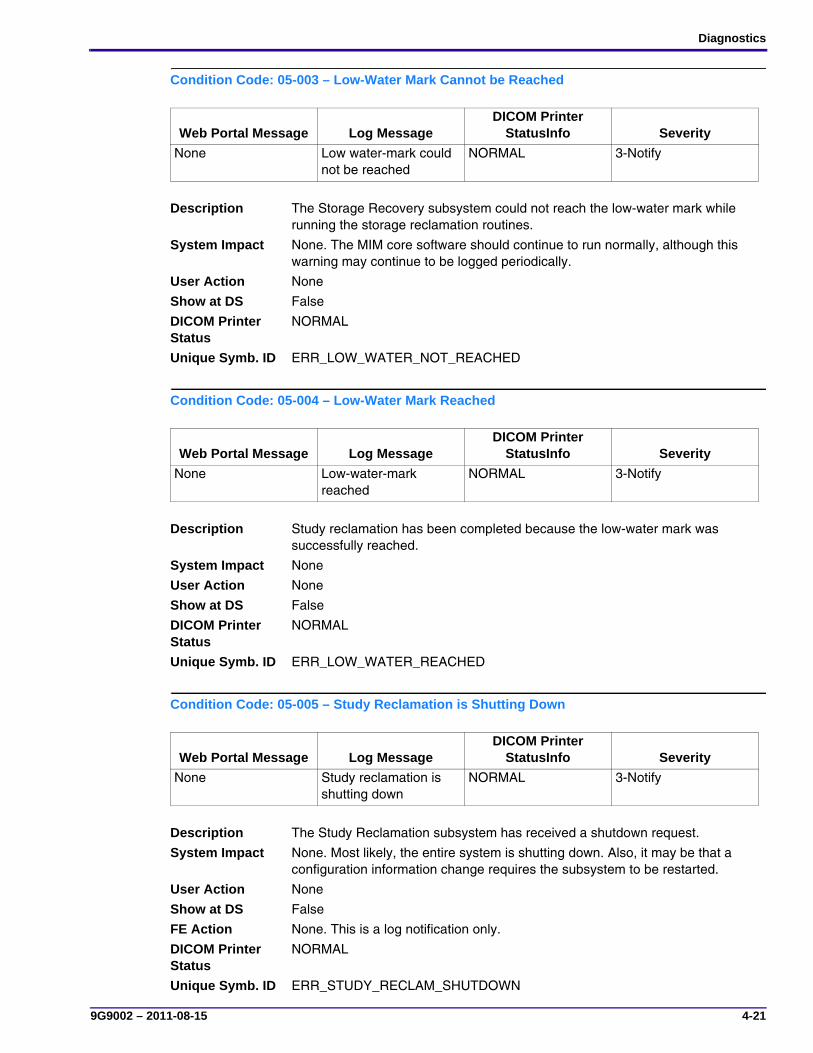
Diagnostics
9G9002 – 2011-08-15 4-21
Condition Code: 05-003 – Low-Water Mark Cannot be Reached
Condition Code: 05-004 – Low-Water Mark Reached
Condition Code: 05-005 – Study Reclamation is Shutting Down
Web Portal Message Log MessageDICOM Printer
StatusInfo Severity
None Low water-mark could not be reached
NORMAL 3-Notify
Description The Storage Recovery subsystem could not reach the low-water mark while running the storage reclamation routines.
System Impact None. The MIM core software should continue to run normally, although this warning may continue to be logged periodically.
User Action None
Show at DS False
DICOM Printer Status
NORMAL
Unique Symb. ID ERR_LOW_WATER_NOT_REACHED
Web Portal Message Log MessageDICOM Printer
StatusInfo Severity
None Low-water-mark reached
NORMAL 3-Notify
Description Study reclamation has been completed because the low-water mark was successfully reached.
System Impact None
User Action None
Show at DS False
DICOM Printer Status
NORMAL
Unique Symb. ID ERR_LOW_WATER_REACHED
Web Portal Message Log MessageDICOM Printer
StatusInfo Severity
None Study reclamation is shutting down
NORMAL 3-Notify
Description The Study Reclamation subsystem has received a shutdown request.
System Impact None. Most likely, the entire system is shutting down. Also, it may be that a configuration information change requires the subsystem to be restarted.
User Action None
Show at DS False
FE Action None. This is a log notification only.
DICOM Printer Status
NORMAL
Unique Symb. ID ERR_STUDY_RECLAM_SHUTDOWN

SERVICE MANUAL
4-22 9G9002 – 2011-08-15
Condition Code: 06-000 – General Delivery Subsystem Error
Condition Code: 06-001 – General Startup Error
Web Portal Message Log MessageDICOM Printer
StatusInfo Severity
None General error in delivery subsystem
NORMAL 3-Notify
Description A general, non-specific error occurred in the Delivery subsystem.
System Impact Unknown. This is an unexpected or unknown error; it is not possible to document specific details.
User Action None
Show at DS False
DICOM Printer Status
NORMAL
Unique Symb. ID ERR_GENERAL_DELIVERY
Web Portal Message Log MessageDICOM Printer
StatusInfo Severity
None General startup error NORMAL 1-Alert
Description A general error occurred while starting the Delivery subsystem.
System Impact Jobs will not be delivered because the software interface for the Delivery subsystem could not be started.
User Action None
Show at DS False
DICOM Printer Status
NORMAL
Unique Symb. ID ERR_STARTUP
NoteRationale for not reporting to user: This error should be recoverable.

Diagnostics
9G9002 – 2011-08-15 4-23
Condition Code: 06-002 – Bad or Missing Configuration Data
Condition Code: 06-101 – Internal Job Processing Error
Web Portal Message Log MessageDICOM Printer
StatusInfo Severity
None Bad or missing configuration information
NORMAL 1-Alert
Description An error occurred while reading the Delivery subsystem configuration information.
System Impact The Delivery subsystem may not execute correctly.
User Action None
Show at DS False
DICOM Printer Status
NORMAL
Unique Symb. ID ERR_BAD_MISSING_CONFIG
NoteLog entry will reflect the specific cause from the listed set of causes.
Web Portal Message Log MessageDICOM Printer
StatusInfo Severity
None General job processing error• Startup error
• Bad or missing configuration data
• Resource allocation error
• Mode switching error
• Multi-threading error
• Message exchange error
• Status callback error
• Inaccessible buffer
• Job is null
• System exception
• Invalid parameter
NORMAL 1-Alert
Description The job delivery component has encountered a general error while processing a job.
System Impact The current job may not be processed to completion due to an internal error.
User Action None
Show at DS False
DICOM Printer Status
NORMAL
Unique Symb. ID ERR_JOB_PROCESS
NoteThe log entry will reflect the specific cause from the listed set of causes.
Rationale for not reporting to user: This error should be recoverable.
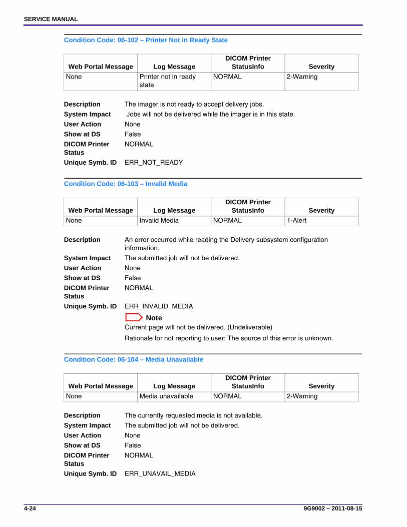
SERVICE MANUAL
4-24 9G9002 – 2011-08-15
Condition Code: 06-102 – Printer Not in Ready State
Condition Code: 06-103 – Invalid Media
Condition Code: 06-104 – Media Unavailable
Web Portal Message Log MessageDICOM Printer
StatusInfo Severity
None Printer not in ready state
NORMAL 2-Warning
Description The imager is not ready to accept delivery jobs.
System Impact Jobs will not be delivered while the imager is in this state.
User Action None
Show at DS False
DICOM Printer Status
NORMAL
Unique Symb. ID ERR_NOT_READY
Web Portal Message Log MessageDICOM Printer
StatusInfo Severity
None Invalid Media NORMAL 1-Alert
Description An error occurred while reading the Delivery subsystem configuration information.
System Impact The submitted job will not be delivered.
User Action None
Show at DS False
DICOM Printer Status
NORMAL
Unique Symb. ID ERR_INVALID_MEDIA
NoteCurrent page will not be delivered. (Undeliverable)
Rationale for not reporting to user: The source of this error is unknown.
Web Portal Message Log MessageDICOM Printer
StatusInfo Severity
None Media unavailable NORMAL 2-Warning
Description The currently requested media is not available.
System Impact The submitted job will not be delivered.
User Action None
Show at DS False
DICOM Printer Status
NORMAL
Unique Symb. ID ERR_UNAVAIL_MEDIA
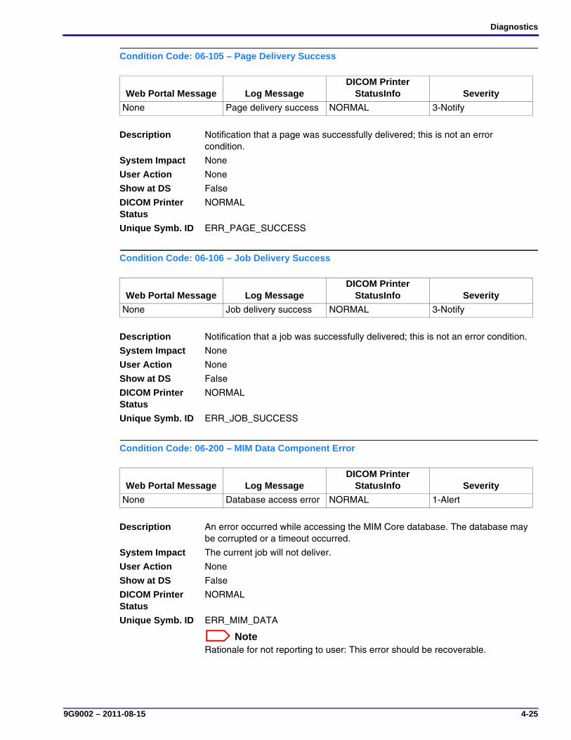
Diagnostics
9G9002 – 2011-08-15 4-25
Condition Code: 06-105 – Page Delivery Success
Condition Code: 06-106 – Job Delivery Success
Condition Code: 06-200 – MIM Data Component Error
Web Portal Message Log MessageDICOM Printer
StatusInfo Severity
None Page delivery success NORMAL 3-Notify
Description Notification that a page was successfully delivered; this is not an error condition.
System Impact None
User Action None
Show at DS False
DICOM Printer Status
NORMAL
Unique Symb. ID ERR_PAGE_SUCCESS
Web Portal Message Log MessageDICOM Printer
StatusInfo Severity
None Job delivery success NORMAL 3-Notify
Description Notification that a job was successfully delivered; this is not an error condition.
System Impact None
User Action None
Show at DS False
DICOM Printer Status
NORMAL
Unique Symb. ID ERR_JOB_SUCCESS
Web Portal Message Log MessageDICOM Printer
StatusInfo Severity
None Database access error NORMAL 1-Alert
Description An error occurred while accessing the MIM Core database. The database may be corrupted or a timeout occurred.
System Impact The current job will not deliver.
User Action None
Show at DS False
DICOM Printer Status
NORMAL
Unique Symb. ID ERR_MIM_DATA
NoteRationale for not reporting to user: This error should be recoverable.

SERVICE MANUAL
4-26 9G9002 – 2011-08-15
Condition Code: 06-300 – Destination Business Logic Error
Condition Code: 06-400 – General Page Builder Error
Web Portal Message Log MessageDICOM Printer
StatusInfo Severity
None Database access error NORMAL 1-Alert
Description An error occurred in the destination business logic component. The database may be corrupted, or a timeout occurred.
System Impact The current job will not deliver.
User Action None
Show at DS False
DICOM Printer Status
NORMAL
Unique Symb. ID ERR_BUS_LOGIC
NoteRationale for not reporting to user: This error should be recoverable.
Web Portal Message Log MessageDICOM Printer
StatusInfo Severity
MIM Core: Image Page Error
General page builder error
NORMAL 1-Alert
Description A general page builder error occurred. Conditions include: • Performance timer errors
• Dumping images at lower level
• Error initializing text, line lists, or member variables
System Impact The current page will not be processed because it could not be rendered due to an internal error.
User Action 1. Resend the print job from the image source.
2. If the error persists, call for service.
Show at DS True
DICOM Printer Status
NORMAL
Unique Symb. ID ERR_PAGE_BUILD
NoteCurrent page will not be delivered. (Undeliverable)
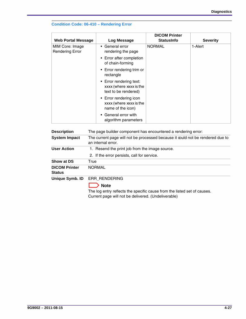
Diagnostics
9G9002 – 2011-08-15 4-27
Condition Code: 06-410 – Rendering Error
Web Portal Message Log MessageDICOM Printer
StatusInfo Severity
MIM Core: Image Rendering Error
• General error rendering the page
• Error after completion of chain-forming
• Error rendering trim or rectangle
• Error rendering text: xxxx (where xxxx is the text to be rendered)
• Error rendering icon xxxx (where xxxx is the name of the icon)
• General error with algorithm parameters
NORMAL 1-Alert
Description The page builder component has encountered a rendering error:
System Impact The current page will not be processed because it could not be rendered due to an internal error.
User Action 1. Resend the print job from the image source.
2. If the error persists, call for service.
Show at DS True
DICOM Printer Status
NORMAL
Unique Symb. ID ERR_RENDERING
NoteThe log entry reflects the specific cause from the listed set of causes.Current page will not be delivered. (Undeliverable)

SERVICE MANUAL
4-28 9G9002 – 2011-08-15
Condition Code: 06-411 – Bad Image Data
Condition Code: 06-412 – Abort Requested
Web Portal Message Log MessageDICOM Printer
StatusInfo Severity
MIM Core: Image Data Error
• Width and/or height less than zero
• Bits beyond pixel depth not zeroed
NORMAL 1-Alert
Description The page builder component has encountered the following image data error: • Width and/or height is less than zero
• Bits beyond the pixel depth are not zeroed
System Impact The current page will not be processed because it could not be rendered due to an internal error.
User Action 1. Resend the print job from the image source.
2. If the error persists, call for service.
Show at DS True
DICOM Printer Status
NORMAL
Unique Symb. ID ERR_IMAGE_DATA
NoteThe log entry reflects the specific cause from the listed set of causes.Current page will not be delivered. (Undeliverable)
Web Portal Message Log MessageDICOM Printer
StatusInfo Severity
None Render abort requested
NORMAL 1-Alert
Description The page builder component has been asked to halt a rendering that is currently in progress.
System Impact The current page will not be processed because rendering was aborted.
User Action None
Show at DS False
DICOM Printer Status
NORMAL
Unique Symb. ID ERR_ABORT_REQ
NoteRationale for not reporting to user: Because the page was canceled via an abort, it may retry successfully.
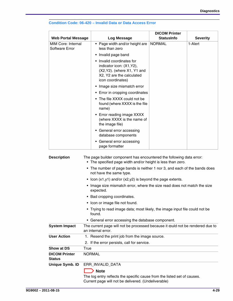
Diagnostics
9G9002 – 2011-08-15 4-29
Condition Code: 06-420 – Invalid Data or Data Access Error
Web Portal Message Log MessageDICOM Printer
StatusInfo Severity
MIM Core: Internal Software Error
• Page width and/or height are less than zero
• Invalid page band
• Invalid coordinates for indicator icon: (X1,Y2), (X2,Y2). (where X1, Y1 and X2, Y2 are the calculated icon coordinates)
• Image size mismatch error
• Error in cropping coordinates
• The file XXXX could not be found (where XXXX is the file name)
• Error reading image XXXX (where XXXX is the name of the image file)
• General error accessing database components
• General error accessing page formatter
NORMAL 1-Alert
Description The page builder component has encountered the following data error: • The specified page width and/or height is less than zero.
• The number of page bands is neither 1 nor 3, and each of the bands does not have the same type.
• Icon (x1,y1) and/or (x2,y2) is beyond the page extents.
• Image size mismatch error, where the size read does not match the size expected.
• Bad cropping coordinates.
• Icon or image file not found.
• Trying to read image data; most likely, the image input file could not be found.
• General error accessing the database component.
System Impact The current page will not be processed because it could not be rendered due to an internal error.
User Action 1. Resend the print job from the image source.
2. If the error persists, call for service.
Show at DS True
DICOM Printer Status
NORMAL
Unique Symb. ID ERR_INVALID_DATA
NoteThe log entry reflects the specific cause from the listed set of causes.Current page will not be delivered. (Undeliverable)

SERVICE MANUAL
4-30 9G9002 – 2011-08-15
Condition Code: 06-430 – Chain-building Error
Web Portal Message Log MessageDICOM Printer
StatusInfo Severity
MIM Core: Internal Software Error
• General error building image processing chain
• Error in tonescaling xxxx (where xxxx is the specific tonescaling problem)
• Error forming the color processing chain
• Error in layout chain
• Error forming the printer processing chain
NORMAL 1-Alert
Description The page builder has encountered one of the following errors while building the image processing chain:
• General chain-building error
• Tonescaling error, usually an error in the transfer function tables (TFT), preference look up table (PLUT), or curve shape
• Error forming the color processing chain, including missing ICC profile files
• Layout chain error, including bad rotation and/or flip parameters
• Error forming the imager processing chain
System Impact Unknown
User Action 1. Resend the print job from the image source.
2. If the error persists, call for service.
Show at DS True
DICOM Printer Status
NORMAL
Unique Symb. ID ERR_CHAIN_BUILDING
NoteThe log entry reflects the specific cause from the listed set of causes.Current page will not be delivered. (Undeliverable)

Diagnostics
9G9002 – 2011-08-15 4-31
Condition Code: 06-440 – Greater Than 12-bit Image Data Encountered
Web Portal Message Log MessageDICOM Printer
StatusInfo Severity
None sendPage(): myMPageBuilder.RenderPage() call has high bits masked out
NORMAL 2-Warning
Description The 12-bit image data had pixels that were greater than 12 bits.
System Impact None. The system will automatically compensate for the problem.
User Action None
Show at DS False
DICOM Printer Status
NORMAL
Unique Symb. ID ERR_OVER_12_BIT_IMAGE

SERVICE MANUAL
4-32 9G9002 – 2011-08-15
Condition Code: 06-500 – Internal Page Delivery Component Error
Web Portal Message Log MessageDICOM Printer
StatusInfo Severity
None • BIND error. Code = YY; Page ID = XXX
• STAGE error. Code = YY; Page ID = XXX
• PRINT error. Code = YY; Page ID = XXX
• EXPOSE error. Code = YY; Page ID = XXX
• Unknown error. Code = YY; Page ID = XXX
NORMAL 1-Alert
Description One of the following internal errors occurred: • Binding error
• Staging error
• Printing error
• Exposure error
• Unknown internal error
System Impact The job may not be delivered due to an internal error communicating with the MCS Interface Server (MIS).
User Action None
Show at DS False
DICOM Printer Status
NORMAL
Unique Symb. ID ERR_PAGE_DELIV_COMP
NoteThe log text will reflect the specific cause from the listed set of causes.
Rationale for not reporting to user: This is an error on an individual job and does not affect imager operation. THe imager will automatically attempt to print the job again.
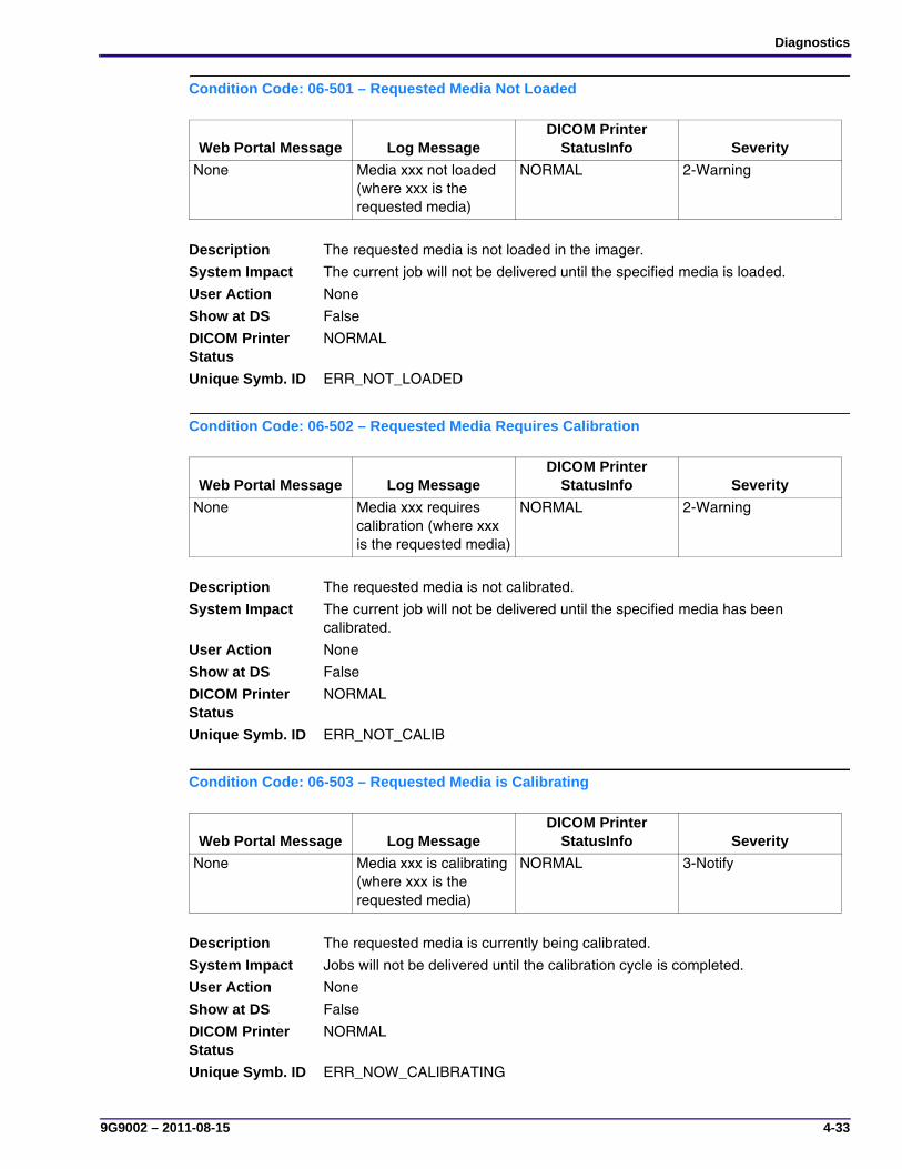
Diagnostics
9G9002 – 2011-08-15 4-33
Condition Code: 06-501 – Requested Media Not Loaded
Condition Code: 06-502 – Requested Media Requires Calibration
Condition Code: 06-503 – Requested Media is Calibrating
Web Portal Message Log MessageDICOM Printer
StatusInfo Severity
None Media xxx not loaded (where xxx is the requested media)
NORMAL 2-Warning
Description The requested media is not loaded in the imager.
System Impact The current job will not be delivered until the specified media is loaded.
User Action None
Show at DS False
DICOM Printer Status
NORMAL
Unique Symb. ID ERR_NOT_LOADED
Web Portal Message Log MessageDICOM Printer
StatusInfo Severity
None Media xxx requires calibration (where xxx is the requested media)
NORMAL 2-Warning
Description The requested media is not calibrated.
System Impact The current job will not be delivered until the specified media has been calibrated.
User Action None
Show at DS False
DICOM Printer Status
NORMAL
Unique Symb. ID ERR_NOT_CALIB
Web Portal Message Log MessageDICOM Printer
StatusInfo Severity
None Media xxx is calibrating (where xxx is the requested media)
NORMAL 3-Notify
Description The requested media is currently being calibrated.
System Impact Jobs will not be delivered until the calibration cycle is completed.
User Action None
Show at DS False
DICOM Printer Status
NORMAL
Unique Symb. ID ERR_NOW_CALIBRATING
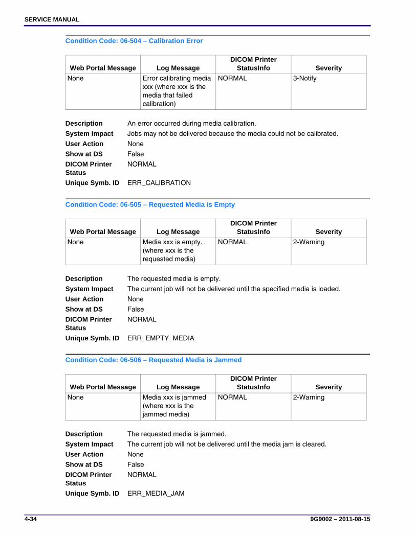
SERVICE MANUAL
4-34 9G9002 – 2011-08-15
Condition Code: 06-504 – Calibration Error
Condition Code: 06-505 – Requested Media is Empty
Condition Code: 06-506 – Requested Media is Jammed
Web Portal Message Log MessageDICOM Printer
StatusInfo Severity
None Error calibrating media xxx (where xxx is the media that failed calibration)
NORMAL 3-Notify
Description An error occurred during media calibration.
System Impact Jobs may not be delivered because the media could not be calibrated.
User Action None
Show at DS False
DICOM Printer Status
NORMAL
Unique Symb. ID ERR_CALIBRATION
Web Portal Message Log MessageDICOM Printer
StatusInfo Severity
None Media xxx is empty. (where xxx is the requested media)
NORMAL 2-Warning
Description The requested media is empty.
System Impact The current job will not be delivered until the specified media is loaded.
User Action None
Show at DS False
DICOM Printer Status
NORMAL
Unique Symb. ID ERR_EMPTY_MEDIA
Web Portal Message Log MessageDICOM Printer
StatusInfo Severity
None Media xxx is jammed (where xxx is the jammed media)
NORMAL 2-Warning
Description The requested media is jammed.
System Impact The current job will not be delivered until the media jam is cleared.
User Action None
Show at DS False
DICOM Printer Status
NORMAL
Unique Symb. ID ERR_MEDIA_JAM
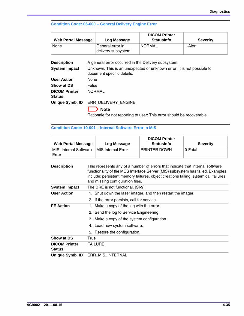
Diagnostics
9G9002 – 2011-08-15 4-35
Condition Code: 06-600 – General Delivery Engine Error
Condition Code: 10-001 – Internal Software Error in MIS
Web Portal Message Log MessageDICOM Printer
StatusInfo Severity
None General error in delivery subsystem
NORMAL 1-Alert
Description A general error occurred in the Delivery subsystem.
System Impact Unknown. This is an unexpected or unknown error; it is not possible to document specific details.
User Action None
Show at DS False
DICOM Printer Status
NORMAL
Unique Symb. ID ERR_DELIVERY_ENGINE
NoteRationale for not reporting to user: This error should be recoverable.
Web Portal Message Log MessageDICOM Printer
StatusInfo Severity
MIS: Internal Software Error
MIS Internal Error PRINTER DOWN 0-Fatal
Description This represents any of a number of errors that indicate that internal software functionality of the MCS Interface Server (MIS) subsystem has failed. Examples include: persistent memory failures, object creations failing, system call failures, and missing configuration files.
System Impact The DRE is not functional. [SI-9]
User Action 1. Shut down the laser imager, and then restart the imager.
2. If the error persists, call for service.
FE Action 1. Make a copy of the log with the error.
2. Send the log to Service Engineering.
3. Make a copy of the system configuration.
4. Load new system software.
5. Restore the configuration.
Show at DS True
DICOM Printer Status
FAILURE
Unique Symb. ID ERR_MIS_INTERNAL
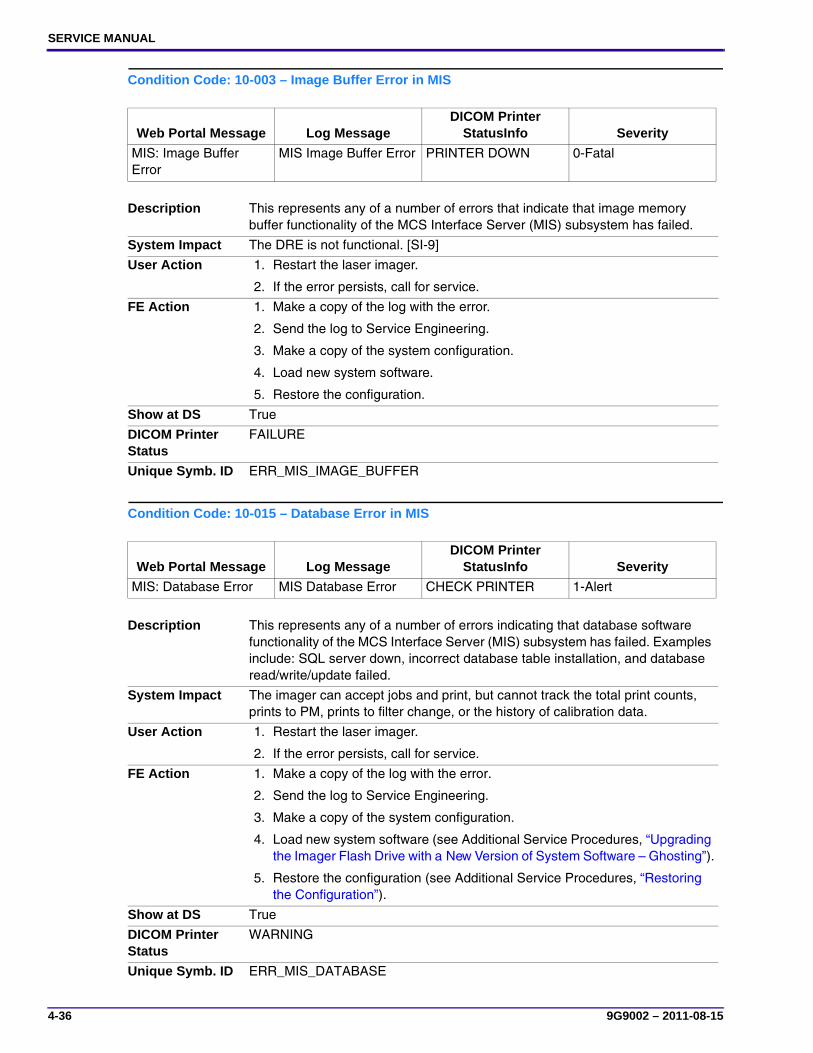
SERVICE MANUAL
4-36 9G9002 – 2011-08-15
Condition Code: 10-003 – Image Buffer Error in MIS
Condition Code: 10-015 – Database Error in MIS
Web Portal Message Log MessageDICOM Printer
StatusInfo Severity
MIS: Image Buffer Error
MIS Image Buffer Error PRINTER DOWN 0-Fatal
Description This represents any of a number of errors that indicate that image memory buffer functionality of the MCS Interface Server (MIS) subsystem has failed.
System Impact The DRE is not functional. [SI-9]
User Action 1. Restart the laser imager.
2. If the error persists, call for service.
FE Action 1. Make a copy of the log with the error.
2. Send the log to Service Engineering.
3. Make a copy of the system configuration.
4. Load new system software.
5. Restore the configuration.
Show at DS True
DICOM Printer Status
FAILURE
Unique Symb. ID ERR_MIS_IMAGE_BUFFER
Web Portal Message Log MessageDICOM Printer
StatusInfo Severity
MIS: Database Error MIS Database Error CHECK PRINTER 1-Alert
Description This represents any of a number of errors indicating that database software functionality of the MCS Interface Server (MIS) subsystem has failed. Examples include: SQL server down, incorrect database table installation, and database read/write/update failed.
System Impact The imager can accept jobs and print, but cannot track the total print counts, prints to PM, prints to filter change, or the history of calibration data.
User Action 1. Restart the laser imager.
2. If the error persists, call for service.
FE Action 1. Make a copy of the log with the error.
2. Send the log to Service Engineering.
3. Make a copy of the system configuration.
4. Load new system software (see Additional Service Procedures, “Upgrading the Imager Flash Drive with a New Version of System Software – Ghosting”).
5. Restore the configuration (see Additional Service Procedures, “Restoring the Configuration”).
Show at DS True
DICOM Printer Status
WARNING
Unique Symb. ID ERR_MIS_DATABASE

Diagnostics
9G9002 – 2011-08-15 4-37
Condition Code: 10-910 – No Communications with the MCS
Condition Code: 13-001 – Service Tool or Web Portal Internal Error
Web Portal Message Log MessageDICOM Printer
StatusInfo Severity
MIS: MCS Communication Failure
MIS to MCS Communications Fail
PRINTER DOWN 0-Fatal
Description This error occurs when the MCS fails to respond to the MIS. The error is declared by the MIS and a log message is generated. This error is a fatal error that will probably result in a service call.
System Impact The imager is unable to print films. The spooler is still able to accept jobs, but new films will not be initiated. Films in progress will not be completed. [SI-3]
User Action 1. Restart the laser imager.
2. If the error persists, call for service.
Show at DS True
DICOM Printer Status
FAILURE
Unique Symb. ID ERR_NO_COMM_MCS
NoteThis error is used to cover all common problems between the MIS and MCS software module. (No hardware connection is involved.)
Web Portal Message Log MessageDICOM Printer
StatusInfo Severity
None General Error in Service Tool Subsystem
NORMAL 3-Notify
Description An internal error occurred that is attributable to software components used by the service tool or Web Portal. (The Web Portal is based on the service tool software, so the source of this error cannot be discerned.) This error code represents any of a number of errors that indicate the internal software functionality of the service tool or Web Portal subsystem has failed. Examples include: persistent memory failures, object creations failing, system call failures, Common Service Platform (CSP) framework errors.
System Impact Service tool operations or Web Portal operations may not be working correctly. The DRE should be functional, but may not respond correctly to the service/portal function being run, or the function may fail.
User Action None
Show at DS False
DICOM Printer Status
NORMAL
Unique Symb. ID ERR_ST_INTERNAL

SERVICE MANUAL
4-38 9G9002 – 2011-08-15
Condition Code: 14-001 – Service Tool or Web Portal Internal Error
Condition Code: 20-154 – MCS Storage Media Failure
Web Portal Message Log MessageDICOM Printer
StatusInfo Severity
None General Error in Web Portal Subsystem
NORMAL 3-Notify
Description An internal error occurred that is attributable to software components used by service tool or Web Portal. (The Web Portal is based on the service tool software, so the source of this error cannot be discerned.) This error code represents any of a number of errors that indicate the internal software functionality of the service tool or Web Portal subsystem failed.
System Impact Service tool operations or Web Portal operations may not be functioning. The DRE should be functional but may not respond correctly to the service/portal function being run, or the function may fail.
Show at DS False
DICOM Printer Status
NORMAL
Unique Symb. ID ERR_WP_INTERNAL
Web Portal Message Log MessageDICOM Printer
StatusInfo Severity
MCS: Internal Communications Failure
MCS failed to read/write to the storage media
ELEC DOWN 0-Fatal
Description This error occurs when the Machine Control System (MCS) detects an error while attempting to read from or write to the storage media. The error clears only when power is cycled.
System Impact The imager is unable to print films. The spooler is still able to accept and queue jobs but new films will not be initiated. Films downstream of the affected subsystem will be completed. All other films will be reprinted. [SI-1]
User Action 1. Shut down the laser imager, then restart the laser imager.
2. If the error persists, call for service
FE Action Perform the actions below in sequence. If an action provides a resolution, do not continue with the other actions.1. De-energize then energize the laser imager.
2. Re-ghost the laser imager (see Additional Service Procedures, “Upgrading the Imager Flash Drive with a New Version of System Software – Ghosting”).
3. Install a new hard drive (see Adjustments and Replacements, “DRE Motherboard and Flash Drive”).
4. Install a new DRE motherboard (see Adjustments and Replacements, “DRE Motherboard Bracket”).
Show at DS True
DICOM Printer Status
FAILURE
Unique Symb. ID ERR_MCS_HARDDRIVE_ACCESS

Diagnostics
9G9002 – 2011-08-15 4-39
Condition Code: 20-155 – MCS Printer Configuration is Incompatible with Hardware
Condition Code: 20-156 – Micro Software Version is Incompatible with MCS Software
Web Portal Message Log MessageDICOM Printer
StatusInfo Severity
Incompatible MCS Printer Configuration for Hardware
MCS printer configuration is incompatible with model hardware
ELEC DOWN 0-Fatal
Description This error occurs when the MCS application reports that the imager configuration is incompatible with the hardware model information. The error clears only when power is cycled.
System Impact The imager is unable to print films. The spooler is still able to accept and queue jobs but new films will not be initiated. Films downstream of the affected subsystem will be completed. All other films will be reprinted. [SI-1]
User Action 1. Shut down the laser imager, then restart the laser imager.
2. If the error persists, call for service.
Show at DS True
DICOM Printer Status
FAILURE
Unique Symb. ID ERR_MCS_INCOMPATIBLE_HARDWARE
Web Portal Message Log MessageDICOM Printer
StatusInfo Severity
Incompatible Software Versions Installed
One or more micros have software versions installed that are incompatible with the MCS version
PRINTER DOWN 0-Fatal
Description This error occurs during MCS diagnostics when the MCS determines that the software version of one or more of the microcontrollers is incompatible with the MCS software version. This error should only happen when the MCS software is being installed or updated. The error is cleared when MCS diagnostics passes.
System Impact The imager is unable to print films. The spooler is still able to accept jobs but new films will not be initiated. Films in progress will not be completed. [SI-3]
User Action 1. Shut down the laser imager, then restart the laser imager.
2. If the error persists, call for service.
FE Action TBD
Show at DS True
DICOM Printer Status
FAILURE
Unique Symb. ID ERR_MCS_INCOMPATIBLE_VERSIONS
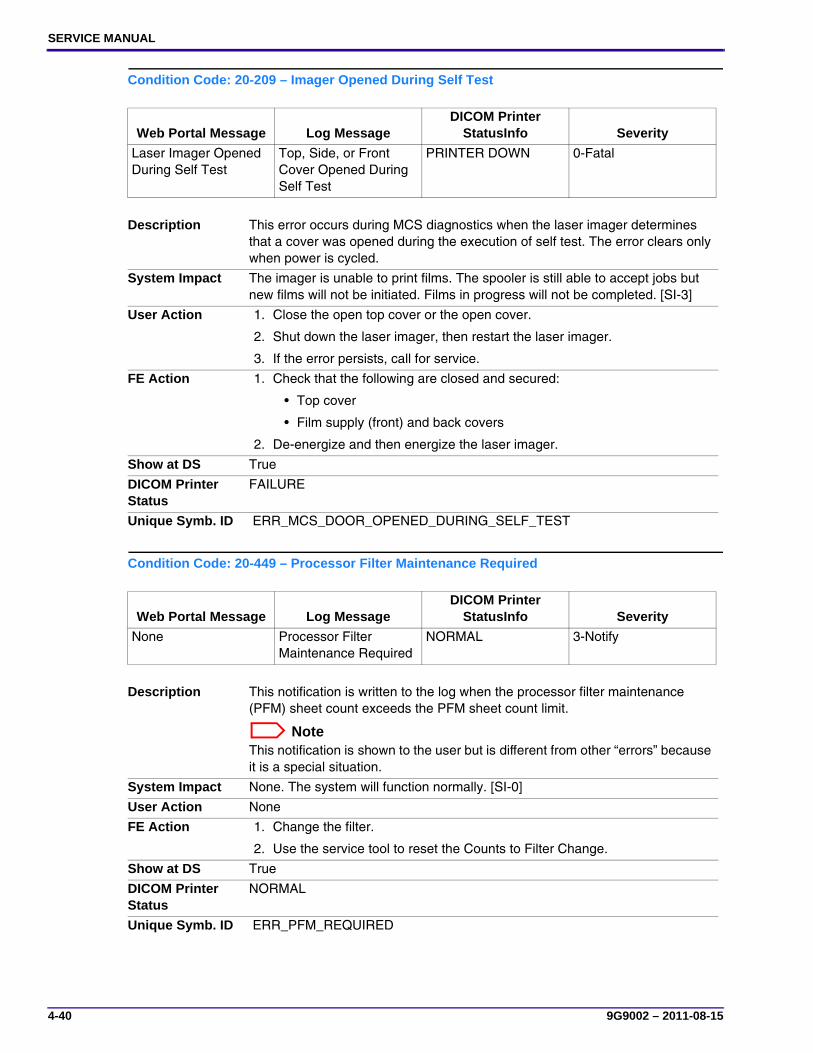
SERVICE MANUAL
4-40 9G9002 – 2011-08-15
Condition Code: 20-209 – Imager Opened During Self Test
Condition Code: 20-449 – Processor Filter Maintenance Required
Web Portal Message Log MessageDICOM Printer
StatusInfo Severity
Laser Imager Opened During Self Test
Top, Side, or Front Cover Opened During Self Test
PRINTER DOWN 0-Fatal
Description This error occurs during MCS diagnostics when the laser imager determines that a cover was opened during the execution of self test. The error clears only when power is cycled.
System Impact The imager is unable to print films. The spooler is still able to accept jobs but new films will not be initiated. Films in progress will not be completed. [SI-3]
User Action 1. Close the open top cover or the open cover.
2. Shut down the laser imager, then restart the laser imager.
3. If the error persists, call for service.
FE Action 1. Check that the following are closed and secured:
• Top cover
• Film supply (front) and back covers
2. De-energize and then energize the laser imager.
Show at DS True
DICOM Printer Status
FAILURE
Unique Symb. ID ERR_MCS_DOOR_OPENED_DURING_SELF_TEST
Web Portal Message Log MessageDICOM Printer
StatusInfo Severity
None Processor Filter Maintenance Required
NORMAL 3-Notify
Description This notification is written to the log when the processor filter maintenance (PFM) sheet count exceeds the PFM sheet count limit.
NoteThis notification is shown to the user but is different from other “errors” because it is a special situation.
System Impact None. The system will function normally. [SI-0]
User Action None
FE Action 1. Change the filter.
2. Use the service tool to reset the Counts to Filter Change.
Show at DS True
DICOM Printer Status
NORMAL
Unique Symb. ID ERR_PFM_REQUIRED
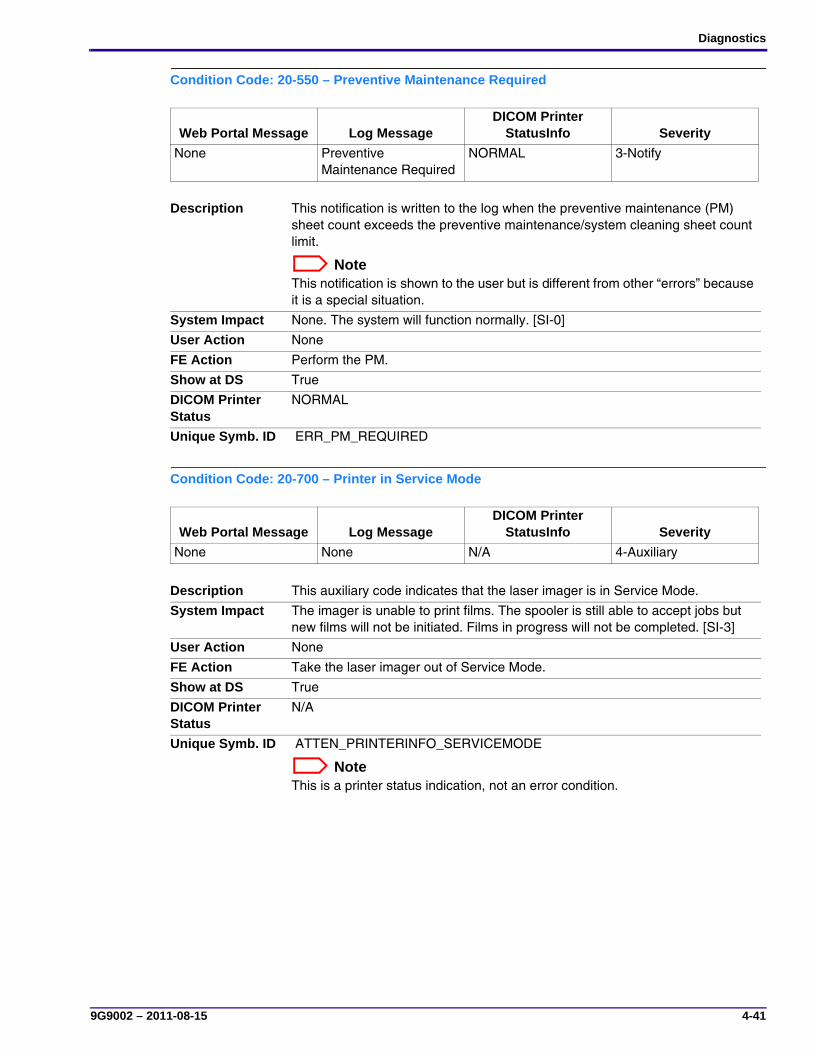
Diagnostics
9G9002 – 2011-08-15 4-41
Condition Code: 20-550 – Preventive Maintenance Required
Condition Code: 20-700 – Printer in Service Mode
Web Portal Message Log MessageDICOM Printer
StatusInfo Severity
None Preventive Maintenance Required
NORMAL 3-Notify
Description This notification is written to the log when the preventive maintenance (PM) sheet count exceeds the preventive maintenance/system cleaning sheet count limit.
NoteThis notification is shown to the user but is different from other “errors” because it is a special situation.
System Impact None. The system will function normally. [SI-0]
User Action None
FE Action Perform the PM.
Show at DS True
DICOM Printer Status
NORMAL
Unique Symb. ID ERR_PM_REQUIRED
Web Portal Message Log MessageDICOM Printer
StatusInfo Severity
None None N/A 4-Auxiliary
Description This auxiliary code indicates that the laser imager is in Service Mode.
System Impact The imager is unable to print films. The spooler is still able to accept jobs but new films will not be initiated. Films in progress will not be completed. [SI-3]
User Action None
FE Action Take the laser imager out of Service Mode.
Show at DS True
DICOM Printer Status
N/A
Unique Symb. ID ATTEN_PRINTERINFO_SERVICEMODE
NoteThis is a printer status indication, not an error condition.
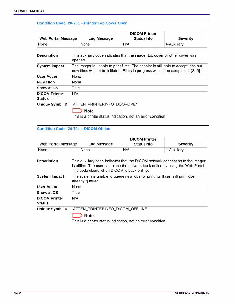
SERVICE MANUAL
4-42 9G9002 – 2011-08-15
Condition Code: 20-701 – Printer Top Cover Open
Condition Code: 20-704 – DICOM Offline
Web Portal Message Log MessageDICOM Printer
StatusInfo Severity
None None N/A 4-Auxiliary
Description This auxiliary code indicates that the imager top cover or other cover was opened.
System Impact The imager is unable to print films. The spooler is still able to accept jobs but new films will not be initiated. Films in progress will not be completed. [SI-3]
User Action None
FE Action None
Show at DS True
DICOM Printer Status
N/A
Unique Symb. ID ATTEN_PRINTERINFO_DOOROPEN
NoteThis is a printer status indication, not an error condition.
Web Portal Message Log MessageDICOM Printer
StatusInfo Severity
None None N/A 4-Auxiliary
Description This auxiliary code indicates that the DICOM network connection to the imager is offline. The user can place the network back online by using the Web Portal. The code clears when DICOM is back online.
System Impact The system is unable to queue new jobs for printing. It can still print jobs already queued.
User Action None
Show at DS True
DICOM Printer Status
N/A
Unique Symb. ID ATTEN_PRINTERINFO_DICOM_OFFLINE
NoteThis is a printer status indication, not an error condition.
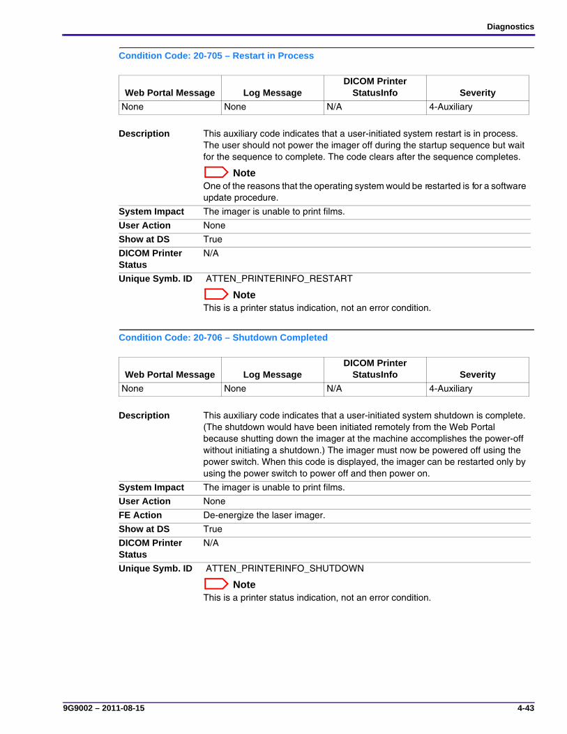
Diagnostics
9G9002 – 2011-08-15 4-43
Condition Code: 20-705 – Restart in Process
Condition Code: 20-706 – Shutdown Completed
Web Portal Message Log MessageDICOM Printer
StatusInfo Severity
None None N/A 4-Auxiliary
Description This auxiliary code indicates that a user-initiated system restart is in process. The user should not power the imager off during the startup sequence but wait for the sequence to complete. The code clears after the sequence completes.
NoteOne of the reasons that the operating system would be restarted is for a software update procedure.
System Impact The imager is unable to print films.
User Action None
Show at DS True
DICOM Printer Status
N/A
Unique Symb. ID ATTEN_PRINTERINFO_RESTART
NoteThis is a printer status indication, not an error condition.
Web Portal Message Log MessageDICOM Printer
StatusInfo Severity
None None N/A 4-Auxiliary
Description This auxiliary code indicates that a user-initiated system shutdown is complete. (The shutdown would have been initiated remotely from the Web Portal because shutting down the imager at the machine accomplishes the power-off without initiating a shutdown.) The imager must now be powered off using the power switch. When this code is displayed, the imager can be restarted only by using the power switch to power off and then power on.
System Impact The imager is unable to print films.
User Action None
FE Action De-energize the laser imager.
Show at DS True
DICOM Printer Status
N/A
Unique Symb. ID ATTEN_PRINTERINFO_SHUTDOWN
NoteThis is a printer status indication, not an error condition.
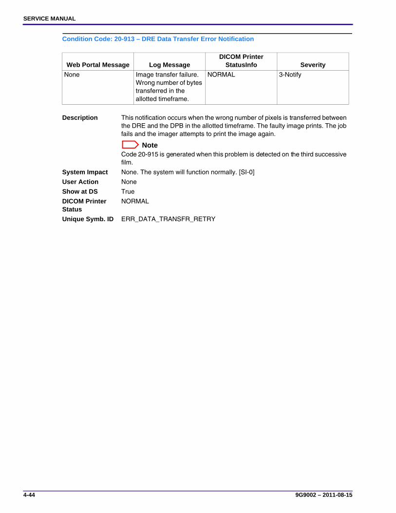
SERVICE MANUAL
4-44 9G9002 – 2011-08-15
Condition Code: 20-913 – DRE Data Transfer Error Notification
Web Portal Message Log MessageDICOM Printer
StatusInfo Severity
None Image transfer failure. Wrong number of bytes transferred in the allotted timeframe.
NORMAL 3-Notify
Description This notification occurs when the wrong number of pixels is transferred between the DRE and the DPB in the allotted timeframe. The faulty image prints. The job fails and the imager attempts to print the image again.
NoteCode 20-915 is generated when this problem is detected on the third successive film.
System Impact None. The system will function normally. [SI-0]
User Action None
Show at DS True
DICOM Printer Status
NORMAL
Unique Symb. ID ERR_DATA_TRANSFR_RETRY
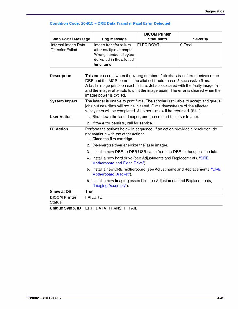
Diagnostics
9G9002 – 2011-08-15 4-45
Condition Code: 20-915 – DRE Data Transfer Fatal Error Detected
Web Portal Message Log MessageDICOM Printer
StatusInfo Severity
Internal Image Data Transfer Failed
Image transfer failure after multiple attempts. Wrong number of bytes delivered in the allotted timeframe.
ELEC DOWN 0-Fatal
Description This error occurs when the wrong number of pixels is transferred between the DRE and the MCS board in the allotted timeframe on 3 successive films. A faulty image prints on each failure. Jobs associated with the faulty image fail, and the imager attempts to print the image again. The error is cleared when the imager power is cycled.
System Impact The imager is unable to print films. The spooler is still able to accept and queue jobs but new films will not be initiated. Films downstream of the affected subsystem will be completed. All other films will be reprinted. [SI-1]
User Action 1. Shut down the laser imager, and then restart the laser imager.
2. If the error persists, call for service.
FE Action Perform the actions below in sequence. If an action provides a resolution, do not continue with the other actions.1. Close the film cartridge.
2. De-energize then energize the laser imager.
3. Install a new DRE-to-DPB USB cable from the DRE to the optics module.
4. Install a new hard drive (see Adjustments and Replacements, “DRE Motherboard and Flash Drive”).
5. Install a new DRE motherboard (see Adjustments and Replacements, “DRE Motherboard Bracket”).
6. Install a new imaging assembly (see Adjustments and Replacements, “Imaging Assembly”).
Show at DS True
DICOM Printer Status
FAILURE
Unique Symb. ID ERR_DATA_TRANSFR_FAIL

SERVICE MANUAL
4-46 9G9002 – 2011-08-15
Condition Code: 20-919 – DRE Image Render Incomplete
Condition Code: 21-002 – Film Supply in Manual Mode
Web Portal Message Log MessageDICOM Printer
StatusInfo Severity
Internal Image Data Render Failed
Image Render did not complete. ELEC DOWN 0-Fatal
Description This error occurs when image data transfer between the DRE and the MCS is interrupted and does not complete within a reasonable time. The error is cleared when the imager power is cycled.
System Impact The imager is unable to print films. The spooler is still able to accept and queue jobs, but new films will not be initiated. Films downstream of the affected subsystem will be completed. All other films will be reprinted. [SI-1]
User Action 1. Shut down the laser imager, and then restart the laser imager.
2. If the error persists, call for service.
FE Action Perform the actions below in sequence. If an action provides a resolution, do not continue with the other actions.1. Close the film cartridge.
2. De-energize then energize the laser imager.
3. Install a new DRE-to-DPB USB cable from the DRE to the optics module.
4. Install a new hard drive (see Adjustments and Replacements, “DRE Motherboard and Flash Drive”).
5. Install a new DRE motherboard (see Adjustments and Replacements, “DRE Motherboard Bracket”).
6. Install a new imaging assembly (see Adjustments and Replacements, “Imaging Assembly”).
Show at DS True
DICOM Printer Status
FAILURE
Unique Symb. ID ERR_DATA_RENDER_FAIL
Web Portal Message Log MessageDICOM Printer
StatusInfo Severity
None None N/A 4-Auxiliary
Description This auxiliary code indicates that the supply is operating in Manual Mode. The image quality is not within the normal range.
System Impact None. The system will function normally. [SI-0]
User Action None
Show at DS True
DICOM Printer Status
N/A
Unique Symb. ID ATTEN_FILMTRAYSTATE_UPPER_MANUAL_MODE
NoteThis is a printer status indication, not an error condition.

Diagnostics
9G9002 – 2011-08-15 4-47
Condition Code: 21-116 – Film Pickup Failed
Web Portal Message Log MessageDICOM Printer
StatusInfo Severity
Film Jam in Area 1 Film Supply: Film Pickup Failure. Film did not lift successfully as indicated by SOP sensor (S6).
FILM TRANS ERR 1-Alert
Description This error occurs if, on the third successive attempt, the imager fails to pick up a sheet of film as indicated by the Exposure Transport SOP sensor (S6). The film has most likely fallen back down onto the cartridge. The error is cleared when a film cartridge is removed and then re-inserted.
System Impact Cannot print from the loaded film cartridge. The spooler is still able to accept and queue jobs. [SI-2]
User Action 1. Close the film cartridge.
2. Remove the film cartridge from the laser imager.
3. Remove any misplaced films from Area 1.
4. If Area 1 did not contain misplaced films, take the cartridge to a dark room and remove the cartridge cover. Remove any misplaced films and reapply the cartridge cover.
5. Re-insert the cartridge.
FE Action Perform the actions below in sequence. If an action provides a resolution, do not continue with the other actions.1. De-energize, and then energize the laser imager.
2. Do the following:
Check: If an existing problem:
the film cartridge Install a new film cartridge.
for a film jam See “Film Jam in Area 1 – Error Code 116 (Web Portal code 21116)”.
for an obstruction Remove the obstruction.
all connectors and cables Seat all connectors.
film separated sensor Install a new sensor (see Adjustments and Replacements, “Film Contact Sensor”).
the pickup home sensor Install a new sensor (see Adjustments and Replacements, “Pickup Home Sensor”).
the film contact sensor Install a new sensor (see Adjustments and Replacements, “Film Contact Sensor”).
the suction cups Install new cups (see Adjustments and Replacements, “Suction Cup”).
the vacuum pump Install a new pump (see Adjustments and Replacements, “Vacuum Pump”).
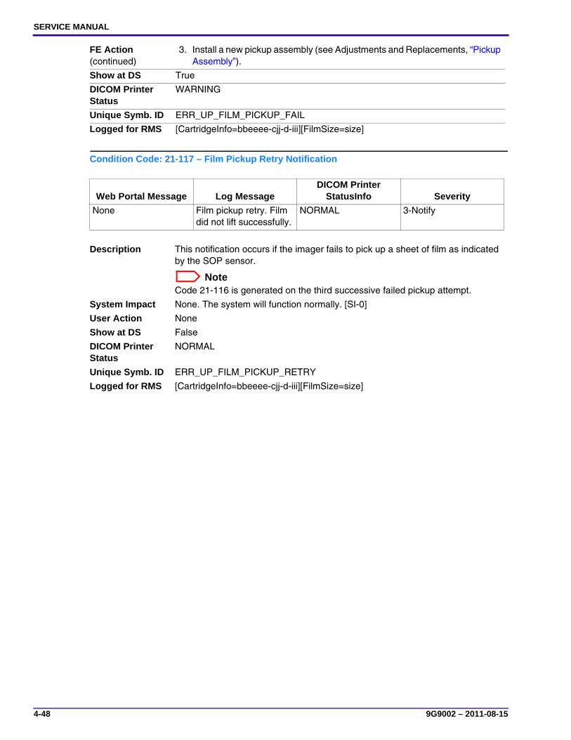
SERVICE MANUAL
4-48 9G9002 – 2011-08-15
Condition Code: 21-117 – Film Pickup Retry Notification
FE Action (continued)
3. Install a new pickup assembly (see Adjustments and Replacements, “Pickup Assembly”).
Show at DS True
DICOM Printer Status
WARNING
Unique Symb. ID ERR_UP_FILM_PICKUP_FAIL
Logged for RMS [CartridgeInfo=bbeeee-cjj-d-iii][FilmSize=size]
Web Portal Message Log MessageDICOM Printer
StatusInfo Severity
None Film pickup retry. Film did not lift successfully.
NORMAL 3-Notify
Description This notification occurs if the imager fails to pick up a sheet of film as indicated by the SOP sensor.
NoteCode 21-116 is generated on the third successive failed pickup attempt.
System Impact None. The system will function normally. [SI-0]
User Action None
Show at DS False
DICOM Printer Status
NORMAL
Unique Symb. ID ERR_UP_FILM_PICKUP_RETRY
Logged for RMS [CartridgeInfo=bbeeee-cjj-d-iii][FilmSize=size]
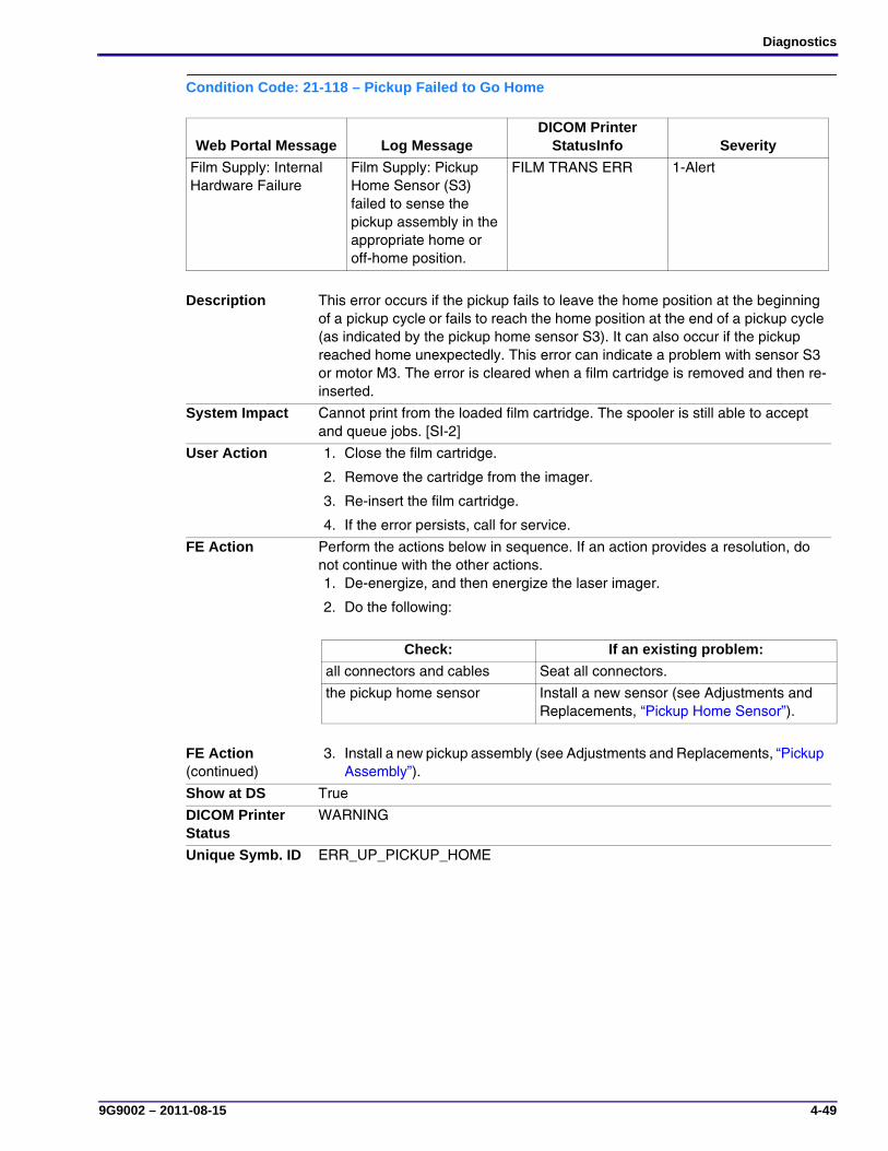
Diagnostics
9G9002 – 2011-08-15 4-49
Condition Code: 21-118 – Pickup Failed to Go Home
Web Portal Message Log MessageDICOM Printer
StatusInfo Severity
Film Supply: Internal Hardware Failure
Film Supply: Pickup Home Sensor (S3) failed to sense the pickup assembly in the appropriate home or off-home position.
FILM TRANS ERR 1-Alert
Description This error occurs if the pickup fails to leave the home position at the beginning of a pickup cycle or fails to reach the home position at the end of a pickup cycle (as indicated by the pickup home sensor S3). It can also occur if the pickup reached home unexpectedly. This error can indicate a problem with sensor S3 or motor M3. The error is cleared when a film cartridge is removed and then re-inserted.
System Impact Cannot print from the loaded film cartridge. The spooler is still able to accept and queue jobs. [SI-2]
User Action 1. Close the film cartridge.
2. Remove the cartridge from the imager.
3. Re-insert the film cartridge.
4. If the error persists, call for service.
FE Action Perform the actions below in sequence. If an action provides a resolution, do not continue with the other actions.1. De-energize, and then energize the laser imager.
2. Do the following:
Check: If an existing problem:
all connectors and cables Seat all connectors.
the pickup home sensor Install a new sensor (see Adjustments and Replacements, “Pickup Home Sensor”).
FE Action (continued)
3. Install a new pickup assembly (see Adjustments and Replacements, “Pickup Assembly”).
Show at DS True
DICOM Printer Status
WARNING
Unique Symb. ID ERR_UP_PICKUP_HOME

SERVICE MANUAL
4-50 9G9002 – 2011-08-15
Condition Code: 21-119 – Film Contact Failure
Web Portal Message Log MessageDICOM Printer
StatusInfo Severity
Film Supply: Internal Hardware Failure
Film Supply: Film contact sensor (S4) failed to confirm that the pickup arm assembly lowered and contacted the film
FILM TRANS ERR 1-Alert
Description This error occurs only while attempting to pick up a film or checking for film in the cartridge. This error can occur when the contact sensor was active when the pickup was at home, or when the contact sensor is stuck on. The most likely cause of the error is a failed contact sensor (S4).The error is cleared when a film cartridge is removed and then re-inserted.
System Impact Cannot print from the loaded film cartridge. The spooler is still able to accept and queue jobs. [SI-2]
User Action 1. Close the film cartridge.
2. Remove the film cartridge from the laser imager.
3. Re-insert the cartridge.
4. If the error persists, call for service.
FE Action Perform the actions below in sequence. If an action provides a resolution, do not continue with the other actions.1. De-energize, and then energize the laser imager.
2. Do the following:
Check: If an existing problem:
the film cartridge Install a new film cartridge.
for a film jam Remove films.
all connectors and cables Seat all connectors.
the pickup home sensor Install a new sensor (see Adjustments and Replacements, “Pickup Home Sensor”).
the film contact sensor Install a new sensor (see Adjustments and Replacements, “Film Contact Sensor”).
FE Action (continued)
3. Install a new pickup assembly (see Adjustments and Replacements, “Pickup Assembly”).
Show at DS True
DICOM Printer Status
WARNING
Unique Symb. ID ERR_UP_FILM_CONTACT
Logged for RMS [CartridgeInfo=bbeeee-cjj-d-iii][FilmSize=size]

Diagnostics
9G9002 – 2011-08-15 4-51
Condition Code: 21-125 – Feed Roller Nip Failure
Web Portal Message Log MessageDICOM Printer
StatusInfo Severity
Film Supply: Internal Hardware Failure
Film Supply: Feed Roller Sensor (S5) failed to detect feed roller open/closed position.
FILM TRANS ERR 1-Alert
Description This error occurs if the feed roller nip sensor (S5) does not change from unblocked to blocked when opening or from blocked to unblocked when closing. The most likely cause is the motor (M1) did not turn or the sensor did not detect the motion.The error is cleared when a film cartridge is removed and then re-inserted.
System Impact Cannot print from the loaded film cartridge. The spooler is still able to accept and queue jobs. [SI-2]
User Action 1. Close the film cartridge.
2. Remove the film cartridge from the laser imager.
3. Re-insert the cartridge.
4. If the error persists, call for service.
FE Action Perform the actions below in sequence. If an action provides a resolution, do not continue with the other actions.1. De-energize then energize the laser imager.
2. Do the following:
Check: If an existing problem:
all connectors and cables Seat all connectors.
the feed roller NIP sensor Install a new sensor.
the feed roller NIP open/close motor
Install a new motor (see Adjustments and Replacements, “Feed Roller Motor”).
FE Action (continued)
3. Install a new pickup assembly (see Adjustments and Replacements, “Pickup Assembly”).
Show at DS True
DICOM Printer Status
WARNING
Unique Symb. ID ERR_UP_FEED_ROLLER
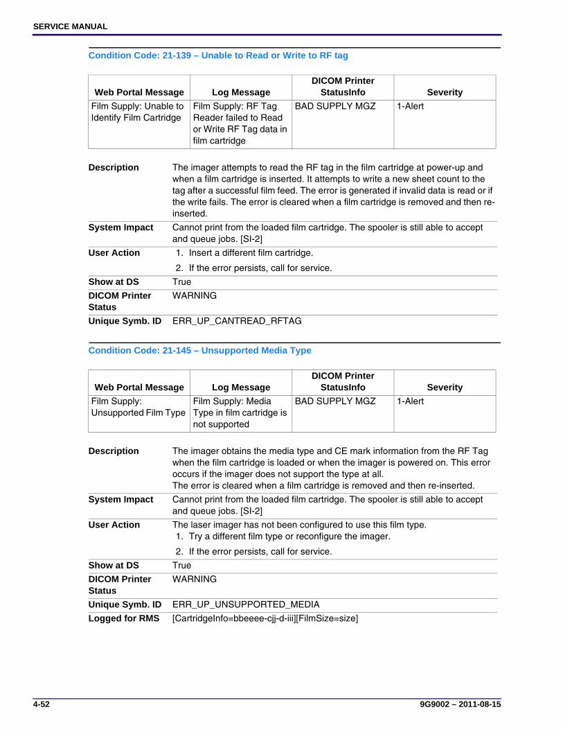
SERVICE MANUAL
4-52 9G9002 – 2011-08-15
Condition Code: 21-139 – Unable to Read or Write to RF tag
Condition Code: 21-145 – Unsupported Media Type
Web Portal Message Log MessageDICOM Printer
StatusInfo Severity
Film Supply: Unable to Identify Film Cartridge
Film Supply: RF Tag Reader failed to Read or Write RF Tag data in film cartridge
BAD SUPPLY MGZ 1-Alert
Description The imager attempts to read the RF tag in the film cartridge at power-up and when a film cartridge is inserted. It attempts to write a new sheet count to the tag after a successful film feed. The error is generated if invalid data is read or if the write fails. The error is cleared when a film cartridge is removed and then re-inserted.
System Impact Cannot print from the loaded film cartridge. The spooler is still able to accept and queue jobs. [SI-2]
User Action 1. Insert a different film cartridge.
2. If the error persists, call for service.
Show at DS True
DICOM Printer Status
WARNING
Unique Symb. ID ERR_UP_CANTREAD_RFTAG
Web Portal Message Log MessageDICOM Printer
StatusInfo Severity
Film Supply: Unsupported Film Type
Film Supply: Media Type in film cartridge is not supported
BAD SUPPLY MGZ 1-Alert
Description The imager obtains the media type and CE mark information from the RF Tag when the film cartridge is loaded or when the imager is powered on. This error occurs if the imager does not support the type at all. The error is cleared when a film cartridge is removed and then re-inserted.
System Impact Cannot print from the loaded film cartridge. The spooler is still able to accept and queue jobs. [SI-2]
User Action The laser imager has not been configured to use this film type.1. Try a different film type or reconfigure the imager.
2. If the error persists, call for service.
Show at DS True
DICOM Printer Status
WARNING
Unique Symb. ID ERR_UP_UNSUPPORTED_MEDIA
Logged for RMS [CartridgeInfo=bbeeee-cjj-d-iii][FilmSize=size]

Diagnostics
9G9002 – 2011-08-15 4-53
Condition Code: 21-146 – Unsupported Media Size
Condition Code: 21-175 – Rollback Failed to Engage Cartridge
Web Portal Message Log MessageDICOM Printer
StatusInfo Severity
Film Supply: Unsupported Film Size
Film Supply: Media Size in film cartridge is not supported
BAD SUPPLY MGZ 1-Alert
Description The imager obtains the media size information from the RF Tag when the film cartridge is loaded or when the imager is powered on. This error occurs if the imager does not support the size.The error is cleared when a film cartridge is removed and then re-inserted.
System Impact Cannot print from the loaded film cartridge. The spooler is still able to accept and queue jobs. [SI-2]
User Action The laser imager has not been configured to use this film size.1. Try a different film size or reconfigure the laser imager.
2. If the error persists, call for service.
Show at DS True
DICOM Printer Status
WARNING
Unique Symb. ID Unique Symb. ID: ERR_UP_WRONG_MEDIA_SIZE
Logged for RMS [CartridgeInfo=bbeeee-cjj-d-iii][FilmSize=size]
Web Portal Message Log MessageDICOM Printer
StatusInfo Severity
Rollback Failed to Engage Cartridge
Rollback failed to engage cartridge
BAD SUPPLY MGZ 1-Alert
Description This error occurs if the rollback mechanism reactivates at the home position (S2x) because the rollback mechanism is rotating in place. The rollback motor is moving (because the home sensor changes state), but it does not travel toward the open sensor. The most likely cause is a mis-inserted cartridge.The error is cleared when the film supply is closed (as indicated by the supply drawer interlock switch i1x).
System Impact Cannot print from the loaded film cartridge. The spooler is still able to accept and queue jobs. [SI-2].
User Action 1. Insert a new film cartridge.
2. If the error persists, call for service.
Show at DS True
DICOM Printer Status
WARNING
Unique Symb. ID ERR_UP_ROLLBACK_ENGAGE
Logged for RMS [CartridgeInfo=bbeeee-cjj-d-iii][FilmSize=size]

SERVICE MANUAL
4-54 9G9002 – 2011-08-15
Condition Code: 21-177 – Film Cartridge Failed to Close
Web Portal Message Log MessageDICOM Printer
StatusInfo Severity
Film Cartridge Failed to Close Rollback Home Sensor (S2U) failed to activate in specified time
BAD SUPPLY MGZ 1-Alert
Description This error occurs only when attempting to close a film cartridge. (Note that an open cartridge operation always closes the cartridge first, before attempting to open the cartridge.) This error occurs for all rollback close failure conditions. Rollback home sensor (S2x) failure is the most likely cause, but the error can also occur from rollback motor (M6x) failure.The error is cleared when the film supply is closed (as indicated by the supply drawer interlock switch i1x), or when power is cycled.
System Impact Cannot print from the loaded film cartridge. The spooler is still able to accept and queue jobs. [SI-2].
User Action 1. Open the film supply.
2. Remove the left cover,
3. Use the blue knob to rotate the cover roller to the home position.
4. Manually close the cartridge to prevent film fogging.
5. Close the film supply.
6. If the error persists, call for service.
Show at DS True
DICOM Printer Status
WARNING
Unique Symb. ID ERR_UP_FILM_CARTRIDGE_NOT_CLOSE
Logged for RMS [CartridgeInfo=bbeeee-cjj-d-iii][FilmSize=size]
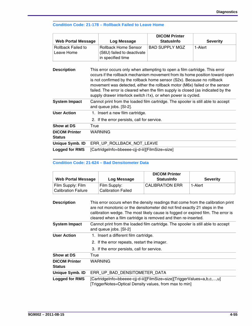
Diagnostics
9G9002 – 2011-08-15 4-55
Condition Code: 21-178 – Rollback Failed to Leave Home
Condition Code: 21-624 – Bad Densitometer Data
Web Portal Message Log MessageDICOM Printer
StatusInfo Severity
Rollback Failed to Leave Home
Rollback Home Sensor (S6U) failed to deactivate in specified time
BAD SUPPLY MGZ 1-Alert
Description This error occurs only when attempting to open a film cartridge. This error occurs if the rollback mechanism movement from its home position toward open is not confirmed by the rollback home sensor (S2x). Because no rollback movement was detected, either the rollback motor (M6x) failed or the sensor failed. The error is cleared when the film supply is closed (as indicated by the supply drawer interlock switch i1x), or when power is cycled.
System Impact Cannot print from the loaded film cartridge. The spooler is still able to accept and queue jobs. [SI-2].
User Action 1. Insert a new film cartridge.
2. If the error persists, call for service.
Show at DS True
DICOM Printer Status
WARNING
Unique Symb. ID ERR_UP_ROLLBACK_NOT_LEAVE
Logged for RMS [CartridgeInfo=bbeeee-cjj-d-iii][FilmSize=size]
Web Portal Message Log MessageDICOM Printer
StatusInfo Severity
Film Supply: Film Calibration Failure
Film Supply: Calibration Failed
CALIBRATION ERR 1-Alert
Description This error occurs when the density readings that come from the calibration print are not monotonic or the densitometer did not find exactly 21 steps in the calibration wedge. The most likely cause is fogged or expired film. The error is cleared when a film cartridge is removed and then re-inserted.
System Impact Cannot print from the loaded film cartridge. The spooler is still able to accept and queue jobs. [SI-2]
User Action 1. Insert a different film cartridge.
2. If the error repeats, restart the imager.
3. If the error persists, call for service.
Show at DS True
DICOM Printer Status
WARNING
Unique Symb. ID ERR_UP_BAD_DENSITOMETER_DATA
Logged for RMS [CartridgeInfo=bbeeee-cjj-d-iii][FilmSize=size][TriggerValues=a,b,c,...,u][TriggerNotes=Optical Density values, from max to min]

SERVICE MANUAL
4-56 9G9002 – 2011-08-15
Condition Code: 21-631 – Dmin Not Met
Web Portal Message Log MessageDICOM Printer
StatusInfo Severity
Film Supply: Film Calibration Failure - Dmin Outside Target
Film Supply: Calibration failed - Dmin Not Met
CALIBRATION ERR 1-Alert
Description The error occurs when the calibration sheet does not have a step density at or below the required Dmin value. The most likely causes are expired film or incorrect processor temperature. The error is cleared when a new calibration is initiated or when the film cartridge is removed. Any cartridge using these calibration results will automatically go into AIQC-Manual Mode and will continue printing but with reduced range in achievable densities. A new calibration will be attempted when this cartridge is re-inserted.
System Impact None. The system will function normally. [SI-0]
User Action The minimum density of the film is too high. Calibration results for this film are outside the normal range but will still be used.
If you do not wish to use these calibration results, perform a new calibration on this film or try another film cartridge.
FE Action 1. Check for “fogged” film. If necessary, replace the film.
2. Use the service tool to check the processor temperature and set point for correct values. If necessary, adjust the temperature (see Adjustments and Replacements, “Processor—Drum Temperature Adjustment”).
Show at DS True
DICOM Printer Status
WARNING
Unique Symb. ID ERR_UP_DMIN_NOT_MET
Logged for RMS [CartridgeInfo=bbeeee-cjj-d-iii][FilmSize=size][TriggerValues=a,b,c,...,u][TriggerNotes=Optical Density values, from max to min]
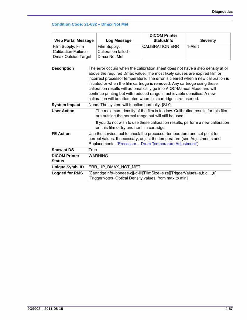
Diagnostics
9G9002 – 2011-08-15 4-57
Condition Code: 21-632 – Dmax Not Met
Web Portal Message Log MessageDICOM Printer
StatusInfo Severity
Film Supply: Film Calibration Failure - Dmax Outside Target
Film Supply: Calibration failed - Dmax Not Met
CALIBRATION ERR 1-Alert
Description The error occurs when the calibration sheet does not have a step density at or above the required Dmax value. The most likely causes are expired film or incorrect processor temperature. The error is cleared when a new calibration is initiated or when the film cartridge is removed. Any cartridge using these calibration results will automatically go into AIQC-Manual Mode and will continue printing but with reduced range in achievable densities. A new calibration will be attempted when this cartridge is re-inserted.
System Impact None. The system will function normally. [SI-0]
User Action The maximum density of the film is too low. Calibration results for this film are outside the normal range but will still be used.
If you do not wish to use these calibration results, perform a new calibration on this film or try another film cartridge.
FE Action Use the service tool to check the processor temperature and set point for correct values. If necessary, adjust the temperature (see Adjustments and Replacements, “Processor—Drum Temperature Adjustment”).
Show at DS True
DICOM Printer Status
WARNING
Unique Symb. ID ERR_UP_DMAX_NOT_MET
Logged for RMS [CartridgeInfo=bbeeee-cjj-d-iii][FilmSize=size][TriggerValues=a,b,c,...,u] [TriggerNotes=Optical Density values, from max to min]
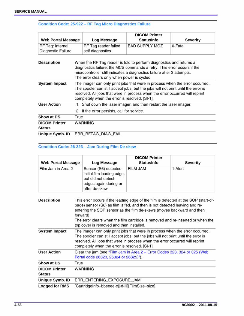
SERVICE MANUAL
4-58 9G9002 – 2011-08-15
Condition Code: 25-922 – RF Tag Micro Diagnostics Failure
Condition Code: 26-323 – Jam During Film De-skew
Web Portal Message Log MessageDICOM Printer
StatusInfo Severity
RF Tag: Internal Diagnostic Failure
RF Tag reader failed self diagnostics
BAD SUPPLY MGZ 0-Fatal
Description When the RF Tag reader is told to perform diagnostics and returns a diagnostics failure, the MCS commands a retry. This error occurs if the microcontroller still indicates a diagnostics failure after 3 attempts.The error clears only when power is cycled.
System Impact The imager can only print jobs that were in process when the error occurred. The spooler can still accept jobs, but the jobs will not print until the error is resolved. All jobs that were in process when the error occurred will reprint completely when the error is resolved. [SI-1]
User Action 1. Shut down the laser imager, and then restart the laser imager.
2. If the error persists, call for service.
Show at DS True
DICOM Printer Status
WARNING
Unique Symb. ID ERR_RFTAG_DIAG_FAIL
Web Portal Message Log MessageDICOM Printer
StatusInfo Severity
Film Jam in Area 2 Sensor (S6) detected initial film leading edge, but did not detect edges again during or after de-skew
FILM JAM 1-Alert
Description This error occurs if the leading edge of the film is detected at the SOP (start-of-page) sensor (S6) as film is fed, and then is not detected leaving and re-entering the SOP sensor as the film de-skews (moves backward and then forward). The error clears when the film cartridge is removed and re-inserted or when the top cover is removed and then installed.
System Impact The imager can only print jobs that were in process when the error occurred. The spooler can still accept jobs, but the jobs will not print until the error is resolved. All jobs that were in process when the error occurred will reprint completely when the error is resolved. [SI-1]
User Action Clear the jam (see “Film Jam in Area 2 – Error Codes 323, 324 or 325 (Web Portal code 26323, 26324 or 26325)”).
Show at DS True
DICOM Printer Status
WARNING
Unique Symb. ID ERR_ENTERING_EXPOSURE_JAM
Logged for RMS [CartridgeInfo=bbeeee-cjj-d-iii][FilmSize=size]

Diagnostics
9G9002 – 2011-08-15 4-59
Condition Code: 26-324 – Jam Leaving Exposure Transport to Accumulator
Web Portal Message Log MessageDICOM Printer
StatusInfo Severity
Film Jam in Area 2 Film Jam Leaving Exposure Transport to accumulator: SOP sensor (S6) failed to detect film trailing edge
FILM JAM 1-Alert
Description This error occurs if the trailing edge (as determined by film direction) is not detected at the SOP (start-of-page) sensor (S6) while it exits toward the accumulator in a timely manner. The error is cleared when either film cartridge is removed and re-inserted or when the top cover is opened and then closed.
System Impact The imager can only print jobs that were in process when the error occurred. The spooler can still accept jobs, but the jobs will not print until the error is resolved. All jobs that were in process when the error occurred will reprint completely when the error is resolved. [SI-1]
User Action Clear the jam (see “Film Jam in Area 2 – Error Codes 323, 324 or 325 (Web Portal code 26323, 26324 or 26325)”).
Show at DS True
DICOM Printer Status
WARNING
Unique Symb. ID ERR_ENTERING_EXPOSURE_JAM
Logged for RMS [CartridgeInfo=bbeeee-cjj-d-iii][FilmSize=size]

SERVICE MANUAL
4-60 9G9002 – 2011-08-15
Condition Code: 26-325 – Jam Entering Exposure Transport from Accumulator
Web Portal Message Log MessageDICOM Printer
StatusInfo Severity
Film Jam in Area 2 Film Jam Entering Exposure Transport from accumulator: SOP sensor (S6) failed to detect film leading edge
FILM JAM 1-Alert
Description This error occurs if the trailing edge (as determined by film direction) is not detected at the SOP (start-of-page) sensor (S6) when coming from the accumulator in a timely manner.The error is cleared when either a film cartridge is removed and re-inserted or when the top cover is opened and then closed.
System Impact The imager can only print jobs that were in process when the error occurred. The spooler can still accept jobs, but the jobs will not print until the error is resolved. All jobs that were in process when the error occurred will reprint completely when the error is resolved. [SI-1]
User Action Clear the jam (see “Film Jam in Area 2 – Error Codes 323, 324 or 325 (Web Portal code 26323, 26324 or 26325)”).
Show at DS True
DICOM Printer Status
WARNING
Unique Symb. ID ERR_ENTERING_EXPOSURE_JAM
Logged for RMS [CartridgeInfo=bbeeee-cjj-d-iii][FilmSize=size]

Diagnostics
9G9002 – 2011-08-15 4-61
Condition Code: 26-326 – Jam Exiting Exposure Transport to Processor
Web Portal Message Log MessageDICOM Printer
StatusInfo Severity
Film Jam in Area 2 or 3 Film Jam Exiting Exposure Transport to Processor: SOP sensor (S6) failed to detect film trailing edge
FILM JAM 1-Alert
Description This error occurs if the trailing edge (as determined by film direction) is not detected at the SOP (start-of-page) sensor (S6) after the film has entered the exposure transport area from the accumulator on its way to the processor. The error is cleared when the film supply is opened then closed. When this error occurs, the processor stops rotating and the heater is turned off. All jobs in the imager will fail and then automatically reprint.
System Impact The imager can only print jobs that were in process when the error occurred. The spooler can still accept jobs, but the jobs will not print until the error is resolved. All jobs that were in process when the error occurred will reprint completely when the error is resolved. [SI-1]
User Action Clear the jam (see “Film Jam in Area 2 or 3 – Error Code 326 (Web Portal code 26326)”).
Show at DS True
DICOM Printer Status
WARNING
Unique Symb. ID ERR_PRE_DENSITOMETER_JAM
Logged for RMS [CartridgeInfo=bbeeee-cjj-d-iii][FilmSize=size]

SERVICE MANUAL
4-62 9G9002 – 2011-08-15
Condition Code: 26-543 – Jam Prior to Densitometer
Web Portal Message Log MessageDICOM Printer
StatusInfo Severity
Film Jam in Area 3 Film Jam Prior to Densitometer: Film at Densitometer sensor (S7) failed to detect film leading edge
FILM JAM 1-Alert
Description This error occurs if the leading edge is not detected at the film-at-densitometer sensor (S7) after the film leaves the exposure area.The error is cleared when the imager top cover is opened then closed. When this error occurs, the processor stops rotating and the heater is turned off. All jobs in the imager will fail and then automatically reprint.
System Impact The imager can only print jobs that were in process when the error occurred. The spooler can still accept jobs, but the jobs will not print until the error is resolved. All jobs that were in process when the error occurred will reprint completely when the error is resolved. [SI-1]
User Action Clear the jam (see “Film Jam in Area 3 – Error Code 543 (Web Portal code 26543)”).
FE Action 1. Clear the jam (see “Film Jam in Area 3 – Error Code 543 (Web Portal code 26543)”).
2. If the above action does not correct the problem or if the problem recurs, it could be caused by a burr or a buildup of film residue on the cooling plate. To check and correct for this:
a. Push the leading edge of a film over the cooling plate.
b. If the film sticks in any way, clean the cooling plate with an alcohol wipe.
c. If necessary, replace the cooling plate.
Show at DS True
DICOM Printer Status
WARNING
Unique Symb. ID ERR_PRE_DENSITOMETER_JAM
Logged for RMS [CartridgeInfo=bbeeee-cjj-d-iii][FilmSize=size]

Diagnostics
9G9002 – 2011-08-15 4-63
Condition Code: 26-544 – Jam at Densitometer
Condition Code: 27-123 – Polygon Motor Error
Web Portal Message Log MessageDICOM Printer
StatusInfo Severity
Film Jam in Area 3 Film Jam at Densitometer: Film at Densitometer sensor (S7) failed to detect film trailing edge
FILM JAM 1-Alert
Description This error occurs if the trailing edge is not detected at the film-at-densitometer sensor (S7) as the film exits the densitometer. The error is cleared when the imager top cover is opened then closed. When this error occurs, the processor stops rotating and the heater is turned off. All jobs in the imager will fail and then automatically reprint.
System Impact The imager can only print jobs that were in process when the error occurred. The spooler can still accept jobs, but the jobs will not print until the error is resolved. All jobs that were in process when the error occurred will reprint completely when the error is resolved. [SI-1]
User Action Clear the jam (see “Film Jam in Area 3 – Error Code 543 (Web Portal code 26543)”).
Show at DS True
DICOM Printer Status
WARNING
Unique Symb. ID ERR_DENSITOMETER_JAM
Logged for RMS [CartridgeInfo=bbeeee-cjj-d-iii][FilmSize=size]
Web Portal Message Log MessageDICOM Printer
StatusInfo Severity
Optics: Internal Hardware Failure
Polygon fails to rotate at desired speed.
ELEC DOWN 0-Fatal
Description This error occurs when the polygon speed measured by the optics module microcontroller is out of range. The error clears only when power is cycled.
System Impact The imager can only print jobs that were in process when the error occurred. The spooler can still accept jobs, but the jobs will not print until the error is resolved. All jobs that were in process when the error occurred will reprint completely when the error is resolved. [SI-1]
User Action 1. Shut down the laser imager, and then restart the imager.
2. If the error persists, call for service.
Show at DS True
DICOM Printer Status
FAILURE
Unique Symb. ID ERR_SPINNER_ERROR
Logged for RMS [TriggerValues=a][TriggerNotes=Polygon Speed]
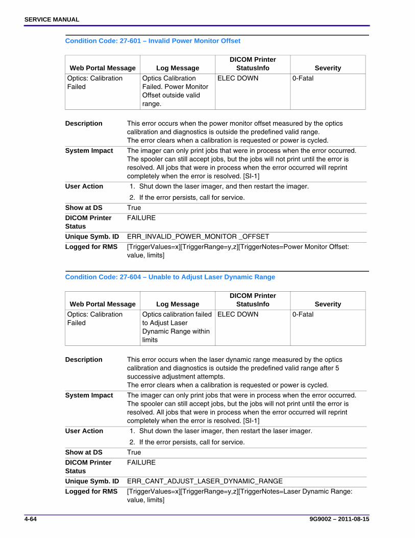
SERVICE MANUAL
4-64 9G9002 – 2011-08-15
Condition Code: 27-601 – Invalid Power Monitor Offset
Condition Code: 27-604 – Unable to Adjust Laser Dynamic Range
Web Portal Message Log MessageDICOM Printer
StatusInfo Severity
Optics: Calibration Failed
Optics Calibration Failed. Power Monitor Offset outside valid range.
ELEC DOWN 0-Fatal
Description This error occurs when the power monitor offset measured by the optics calibration and diagnostics is outside the predefined valid range. The error clears when a calibration is requested or power is cycled.
System Impact The imager can only print jobs that were in process when the error occurred. The spooler can still accept jobs, but the jobs will not print until the error is resolved. All jobs that were in process when the error occurred will reprint completely when the error is resolved. [SI-1]
User Action 1. Shut down the laser imager, and then restart the imager.
2. If the error persists, call for service.
Show at DS True
DICOM Printer Status
FAILURE
Unique Symb. ID ERR_INVALID_POWER_MONITOR _OFFSET
Logged for RMS [TriggerValues=x][TriggerRange=y,z][TriggerNotes=Power Monitor Offset: value, limits]
Web Portal Message Log MessageDICOM Printer
StatusInfo Severity
Optics: Calibration Failed
Optics calibration failed to Adjust Laser Dynamic Range within limits
ELEC DOWN 0-Fatal
Description This error occurs when the laser dynamic range measured by the optics calibration and diagnostics is outside the predefined valid range after 5 successive adjustment attempts. The error clears when a calibration is requested or power is cycled.
System Impact The imager can only print jobs that were in process when the error occurred. The spooler can still accept jobs, but the jobs will not print until the error is resolved. All jobs that were in process when the error occurred will reprint completely when the error is resolved. [SI-1]
User Action 1. Shut down the laser imager, then restart the laser imager.
2. If the error persists, call for service.
Show at DS True
DICOM Printer Status
FAILURE
Unique Symb. ID ERR_CANT_ADJUST_LASER_DYNAMIC_RANGE
Logged for RMS [TriggerValues=x][TriggerRange=y,z][TriggerNotes=Laser Dynamic Range: value, limits]

Diagnostics
9G9002 – 2011-08-15 4-65
Condition Code: 27-607 – Optics Maximum Laser Power Outside Valid Range
Condition Code: 27-608 – Invalid Laser Dynamic Range
Web Portal Message Log MessageDICOM Printer
StatusInfo Severity
Optics: Calibration Failed
Optics calibration detected Optics Maximum Power outside valid range
ELEC DOWN 0-Fatal
Description This error occurs when the maximum laser power measured by the optics calibration and diagnostics is outside the predefined valid range. The error clears when a calibration is requested or power is cycled.
System Impact The imager can only print jobs that were in process when the error occurred. The spooler can still accept jobs, but the jobs will not print until the error is resolved. All jobs that were in process when the error occurred will reprint completely when the error is resolved. [SI-1]
User Action 1. Shut down the laser imager, and then restart the imager.
2. If the error persists, call for service.
Show at DS True
DICOM Printer Status
FAILURE
Unique Symb. ID ERR_OPTICS_MAX_LASER_POWER
Logged for RMS [TriggerValues=x][TriggerRange=y,z][TriggerNotes=Laser Power: value, limits]
Web Portal Message Log MessageDICOM Printer
StatusInfo Severity
None Optics calibration detected laser dynamic range approaching predefined limits
NORMAL 3-Notify
Description This notification occurs when the laser dynamic range has been adjusted and its value is within 10% of the upper or lower limit of the adjustment range.
System Impact None. The system will function normally. [SI-0]
User Action None
FE Action None. This is a log notification only.
Show at DS False
DICOM Printer Status
NORMAL
Unique Symb. ID ERR_OPTICS_LASER_DYNAMIC_RANGE_NEAR_LIMIT
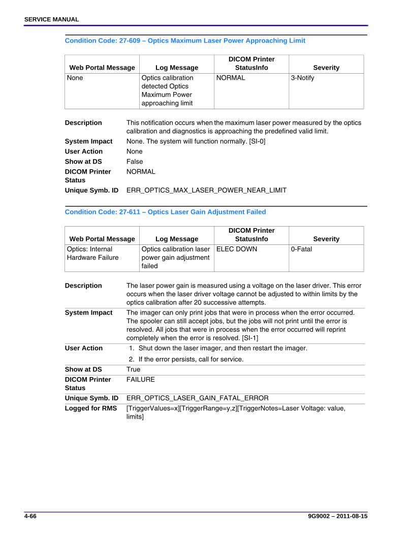
SERVICE MANUAL
4-66 9G9002 – 2011-08-15
Condition Code: 27-609 – Optics Maximum Laser Power Approaching Limit
Condition Code: 27-611 – Optics Laser Gain Adjustment Failed
Web Portal Message Log MessageDICOM Printer
StatusInfo Severity
None Optics calibration detected Optics Maximum Power approaching limit
NORMAL 3-Notify
Description This notification occurs when the maximum laser power measured by the optics calibration and diagnostics is approaching the predefined valid limit.
System Impact None. The system will function normally. [SI-0]
User Action None
Show at DS False
DICOM Printer Status
NORMAL
Unique Symb. ID ERR_OPTICS_MAX_LASER_POWER_NEAR_LIMIT
Web Portal Message Log MessageDICOM Printer
StatusInfo Severity
Optics: Internal Hardware Failure
Optics calibration laser power gain adjustment failed
ELEC DOWN 0-Fatal
Description The laser power gain is measured using a voltage on the laser driver. This error occurs when the laser driver voltage cannot be adjusted to within limits by the optics calibration after 20 successive attempts.
System Impact The imager can only print jobs that were in process when the error occurred. The spooler can still accept jobs, but the jobs will not print until the error is resolved. All jobs that were in process when the error occurred will reprint completely when the error is resolved. [SI-1]
User Action 1. Shut down the laser imager, and then restart the imager.
2. If the error persists, call for service.
Show at DS True
DICOM Printer Status
FAILURE
Unique Symb. ID ERR_OPTICS_LASER_GAIN_FATAL_ERROR
Logged for RMS [TriggerValues=x][TriggerRange=y,z][TriggerNotes=Laser Voltage: value, limits]

Diagnostics
9G9002 – 2011-08-15 4-67
Condition Code: 27-646 – Start of Page Error
Condition Code: 27-650 – Exposure Timeout Error
Web Portal Message Log MessageDICOM Printer
StatusInfo Severity
Optics: Internal Hardware Failure
Optics hardware failed to report start of page although Start of Page sensor (S6) detected film
ELEC DOWN 0-Fatal
Description This error occurs if the optics hardware does not report the start-of-page condition even though the start-of-page (SOP) sensor (S6) did indicate the leading edge of the film has been detected. The image is likely blank, but the film is not jammed and should exit the imager successfully. The error clears only when power is cycled.
System Impact The imager can only print jobs that were in process when the error occurred. The spooler can still accept jobs, but the jobs will not print until the error is resolved. All jobs that were in process when the error occurred will reprint completely when the error is resolved. [SI-1]
User Action 1. Shut down the laser imager, and then restart the imager.
2. If the error persists, call for service.
Show at DS True
DICOM Printer Status
FAILURE
Unique Symb. ID ERR_START_OF_PAGE
Web Portal Message Log MessageDICOM Printer
StatusInfo Severity
Optics: Internal Hardware Failure
Image Exposure time out failure – multiple successive timeouts
ELEC DOWN 0-Fatal
Description This error occurs when the image exposure does not complete in the required time for 3 successive films. The error is cleared when the imager power is cycled.
System Impact The imager can only print jobs that were in process when the error occurred. The spooler can still accept jobs, but the jobs will not print until the error is resolved. All jobs that were in process when the error occurred will reprint completely when the error is resolved. [SI-1]
User Action 1. Shut down the laser imager, and then restart the imager.
2. If the error persists, call for service.
Show at DS True
DICOM Printer Status
FAILURE
Unique Symb. ID ERR_EXPOSE_TMO_FAIL
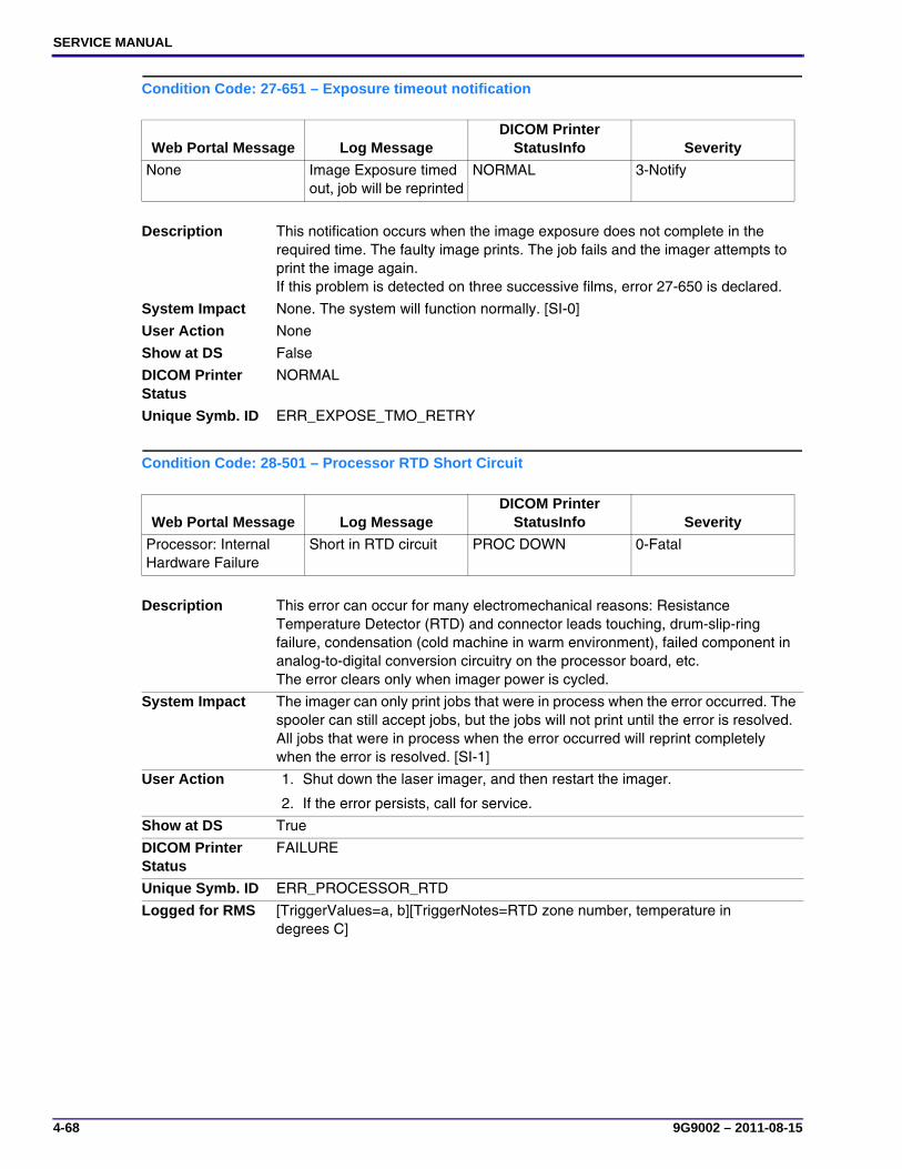
SERVICE MANUAL
4-68 9G9002 – 2011-08-15
Condition Code: 27-651 – Exposure timeout notification
Condition Code: 28-501 – Processor RTD Short Circuit
Web Portal Message Log MessageDICOM Printer
StatusInfo Severity
None Image Exposure timed out, job will be reprinted
NORMAL 3-Notify
Description This notification occurs when the image exposure does not complete in the required time. The faulty image prints. The job fails and the imager attempts to print the image again. If this problem is detected on three successive films, error 27-650 is declared.
System Impact None. The system will function normally. [SI-0]
User Action None
Show at DS False
DICOM Printer Status
NORMAL
Unique Symb. ID ERR_EXPOSE_TMO_RETRY
Web Portal Message Log MessageDICOM Printer
StatusInfo Severity
Processor: Internal Hardware Failure
Short in RTD circuit PROC DOWN 0-Fatal
Description This error can occur for many electromechanical reasons: Resistance Temperature Detector (RTD) and connector leads touching, drum-slip-ring failure, condensation (cold machine in warm environment), failed component in analog-to-digital conversion circuitry on the processor board, etc. The error clears only when imager power is cycled.
System Impact The imager can only print jobs that were in process when the error occurred. The spooler can still accept jobs, but the jobs will not print until the error is resolved. All jobs that were in process when the error occurred will reprint completely when the error is resolved. [SI-1]
User Action 1. Shut down the laser imager, and then restart the imager.
2. If the error persists, call for service.
Show at DS True
DICOM Printer Status
FAILURE
Unique Symb. ID ERR_PROCESSOR_RTD
Logged for RMS [TriggerValues=a, b][TriggerNotes=RTD zone number, temperature in degrees C]

Diagnostics
9G9002 – 2011-08-15 4-69
Condition Code: 28-509 – Processor Failed to Complete Warm-Up
Web Portal Message Log MessageDICOM Printer
StatusInfo Severity
Processor Warm-up Failure
Processor failed to warm up in the specified time
PROC DOWN 0-Fatal
Description There are three primary causes for this error:1. The processor-measured temperature has not locked into ±0.15 °C of the set
point for at least 20 seconds before the end of the warm-up time allotted. The processor electronics have failed. For this case, the allotted time for warm-up will expire. (Resolution: Replace the board.)
2. There was a failure to heat or the warm-up rate was too slow (=/< 3 °C per minute). For this case, the failed SSR status bit should be set. Either the solid-state relay (SSR) or mechanical power relay has failed. (Resolution: Replace the board.)
3. The environment may be too cold or the power source underrated. (Resolution: Repeat the warm-up cycle.)
• The allotted time is calculated from the initial processor drum temperature.
• The error clears only when imager power is cycled.
System Impact The imager can only print jobs that were in process when the error occurred. The spooler can still accept jobs, but the jobs will not print until the error is resolved. All jobs that were in process when the error occurred will reprint completely when the error is resolved. [SI-1]
User Action 1. Shut down the laser imager, then restart the imager.
2. If the error persists, call for service.
Show at DS True
DICOM Printer Status
FAILURE
Unique Symb. ID ERR_PROCESSOR_WARMUP
Logged for RMS [TriggerValues=a, b][TriggerNotes=RTD zone number, temperature in degrees C]

SERVICE MANUAL
4-70 9G9002 – 2011-08-15
Condition Code: 28-510 – Processor RTD Open Circuit
Web Portal Message Log MessageDICOM Printer
StatusInfo Severity
Processor: Internal Hardware Failure
Processor detected a sudden change to infinite resistance in the RTD circuitry
PROC DOWN 0-Fatal
Description This error likely occurred in conjunction with the overheat error. The most likely cause is an opening in the RTD circuit (RTD fractured, drum slip ring failure, wiring harness disconnected, etc.).The error clears only when imager power is cycled.
System Impact The imager can only print jobs that were in process when the error occurred. The spooler can still accept jobs, but the jobs will not print until the error is resolved. All jobs that were in process when the error occurred will reprint completely when the error is resolved. [SI-1]
User Action 1. Shut down the laser imager, then restart the imager.
2. If the error persists, call for service.
Show at DS True
DICOM Printer Status
FAILURE
Unique Symb. ID ERR_PROCESSOR_RTD_OPENLogged for RMS: [TriggerValues=a, b][TriggerNotes=RTD zone number, temperature in degrees C]
Logged for RMS [TriggerValues=a, b][TriggerNotes=RTD zone number, temperature in degrees C]
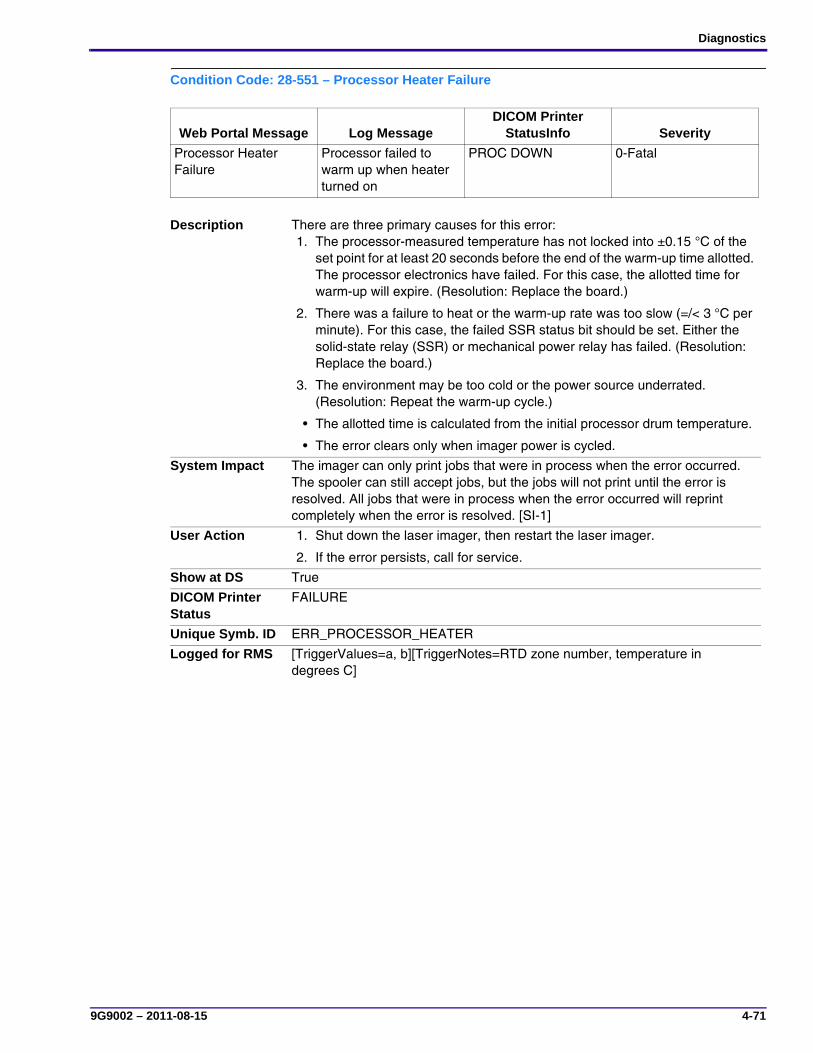
Diagnostics
9G9002 – 2011-08-15 4-71
Condition Code: 28-551 – Processor Heater Failure
Web Portal Message Log MessageDICOM Printer
StatusInfo Severity
Processor Heater Failure
Processor failed to warm up when heater turned on
PROC DOWN 0-Fatal
Description There are three primary causes for this error:1. The processor-measured temperature has not locked into ±0.15 °C of the
set point for at least 20 seconds before the end of the warm-up time allotted. The processor electronics have failed. For this case, the allotted time for warm-up will expire. (Resolution: Replace the board.)
2. There was a failure to heat or the warm-up rate was too slow (=/< 3 °C per minute). For this case, the failed SSR status bit should be set. Either the solid-state relay (SSR) or mechanical power relay has failed. (Resolution: Replace the board.)
3. The environment may be too cold or the power source underrated. (Resolution: Repeat the warm-up cycle.)
• The allotted time is calculated from the initial processor drum temperature.
• The error clears only when imager power is cycled.
System Impact The imager can only print jobs that were in process when the error occurred. The spooler can still accept jobs, but the jobs will not print until the error is resolved. All jobs that were in process when the error occurred will reprint completely when the error is resolved. [SI-1]
User Action 1. Shut down the laser imager, then restart the laser imager.
2. If the error persists, call for service.
Show at DS True
DICOM Printer Status
FAILURE
Unique Symb. ID ERR_PROCESSOR_HEATER
Logged for RMS [TriggerValues=a, b][TriggerNotes=RTD zone number, temperature in degrees C]

SERVICE MANUAL
4-72 9G9002 – 2011-08-15
Condition Code: 28-554 – Over Temperature Errors
Condition Code: 29-924 – Densitometer Failed Offset Reading Diagnostics
Web Portal Message Log MessageDICOM Printer
StatusInfo Severity
Processor Over Temperature
Processor Over Temperature
PROC DOWN 0-Fatal
Description This error occurs if the measured temperature is approximately 148 °C or greater. If there is no corresponding “Processor Open Circuit Error,” then the likely cause is a stuck on solid-state relay (SSR). The software shuts power off to the drum, but the redundant safety feature of the thermal circuit breaker in the drum may also trip (the drum thermal circuit breaker must be manually reset). The error clears only when imager power is cycled.
System Impact The imager can only print jobs that were in process when the error occurred. The spooler can still accept jobs, but the jobs will not print until the error is resolved. All jobs that were in process when the error occurred will reprint completely when the error is resolved. [SI-1]
User Action 1. Shut down the laser imager, then restart the imager.
2. If the error persists, call for service.
Show at DS True
DICOM Printer Status
FAILURE
Unique Symb. ID ERR_OVER_TEMP_ERRORS
Logged for RMS [TriggerValues=a, b][TriggerNotes=RTD zone number, temperature in degrees C]
Web Portal Message Log MessageDICOM Printer
StatusInfo Severity
Densitometer: Internal Diagnostic Failure
Densitometer offset reading out of range with light source off
ELEC DOWN 0-Fatal
Description During a calibration print and during densitometer diagnostics, a reading from the density sensor is taken with the light source turned off. The error occurs if the microcontroller reports the reading out of range.The error clears only when imager power is cycled.
System Impact The imager can only print jobs that were in process when the error occurred. The spooler can still accept jobs, but the jobs will not print until the error is resolved. All jobs that were in process when the error occurred will reprint completely when the error is resolved. [SI-1]
User Action 1. Shut down the laser imager, then restart the imager.
2. If the error persists, call for service.
Show at DS True
DICOM Printer Status
FAILURE
Unique Symb. ID ERR_DENSITOMETER_OFFSET_LIGHT_OFF
Logged for RMS [TriggerValues=a, b, c, d][TriggerNotes=Density Reference, Density Offset, Fiducial Reference, Fiducial Offset]

Diagnostics
9G9002 – 2011-08-15 4-73
Condition Code: 29-925 – Densitometer Reference Reading Failed Diagnostics
Condition Code: 29-945 – Densitometer Reference Reading Diagnostics Warning
Web Portal Message Log MessageDICOM Printer
StatusInfo Severity
Densitometer: Internal Diagnostic Failure
Densitometer reference reading out of range with light source on
ELEC DOWN 0-Fatal
Description During a calibration print and during densitometer diagnostics, a reading from the density sensor is taken with the light source turned on. This error occurs when the reading is out of range.
NoteCode 29-945 is generated when this reading is nearing the range limit.
The error clears only when imager power is cycled.
System Impact The imager can only print jobs that were in process when the error occurred. The spooler can still accept jobs, but the jobs will not print until the error is resolved. All jobs that were in process when the error occurred will reprint completely when the error is resolved. [SI-1]
User Action 1. Shut down the laser imager, and then restart the imager.
2. If the error persists, call for service.
Show at DS True
DICOM Printer Status
FAILURE
Unique Symb. ID ERR_DENSITOMETER_REFERENCE_LIGHT_ON
Logged for RMS [TriggerValues=a, b, c, d][TriggerNotes=Density Reference, Density Offset, Fiducial Reference, Fiducial Offset]
Web Portal Message Log MessageDICOM Printer
StatusInfo Severity
None Densitometer reference reading outside of optimal range with light source on
NORMAL 3-Notify
Description During a calibration print and during densitometer diagnostics, a reading from the density sensor is taken with the light source turned on. This notification occurs when the reading is outside of the optimal range (approaching the range limit).
NoteCode 29-925 is generated when this reading is over the range limit.
System Impact None. The system will function normally. [SI-0]
User Action None
Show at DS False
DICOM Printer Status
NORMAL
Unique Symb. ID ERR_DENSITOMETER_OFFSET_LIGHT_ON_NOTICE
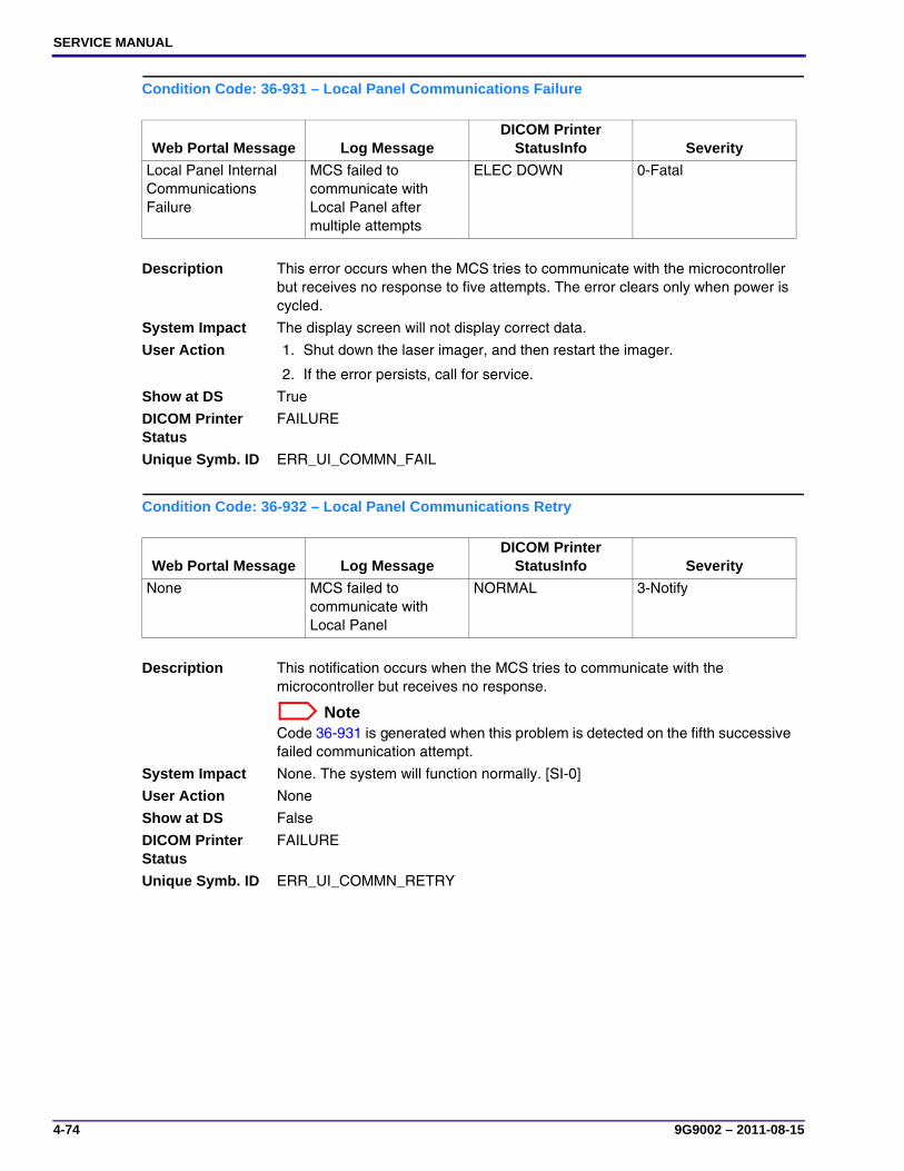
SERVICE MANUAL
4-74 9G9002 – 2011-08-15
Condition Code: 36-931 – Local Panel Communications Failure
Condition Code: 36-932 – Local Panel Communications Retry
Web Portal Message Log MessageDICOM Printer
StatusInfo Severity
Local Panel Internal Communications Failure
MCS failed to communicate with Local Panel after multiple attempts
ELEC DOWN 0-Fatal
Description This error occurs when the MCS tries to communicate with the microcontroller but receives no response to five attempts. The error clears only when power is cycled.
System Impact The display screen will not display correct data.
User Action 1. Shut down the laser imager, and then restart the imager.
2. If the error persists, call for service.
Show at DS True
DICOM Printer Status
FAILURE
Unique Symb. ID ERR_UI_COMMN_FAIL
Web Portal Message Log MessageDICOM Printer
StatusInfo Severity
None MCS failed to communicate with Local Panel
NORMAL 3-Notify
Description This notification occurs when the MCS tries to communicate with the microcontroller but receives no response.
NoteCode 36-931 is generated when this problem is detected on the fifth successive failed communication attempt.
System Impact None. The system will function normally. [SI-0]
User Action None
Show at DS False
DICOM Printer Status
FAILURE
Unique Symb. ID ERR_UI_COMMN_RETRY

Diagnostics
9G9002 – 2011-08-15 4-75
Condition Code: 36-935 – Local Panel Not Receiving Communications
Web Portal Message Log MessageDICOM Printer
StatusInfo Severity
Local Panel: No Communications from MCS
Local Panel not receiving communications from MCS
NORMAL 2-Warning
Description This error occurs when the display screen does not receive communications from the MCS. The display screen waits for 50 seconds, then attempts to invoke communications from the MCS. After an additional 10 seconds, if the display screen has not received MCS communications, this error displays on the display screen. The error clears when the display screen detects MCS communications.
System Impact Unknown. If the MCS is down, the imager will not print films. If the problem is limited to communications, the imager may be able to print films.
User Action 1. Shut down the laser imager, and then restart the imager.
2. If the error persists, call for service.
FE Action None
Show at DS True
DICOM Printer Status
NORMAL
Unique Symb. ID ERR_UI_MCS_COMMN_FAIL
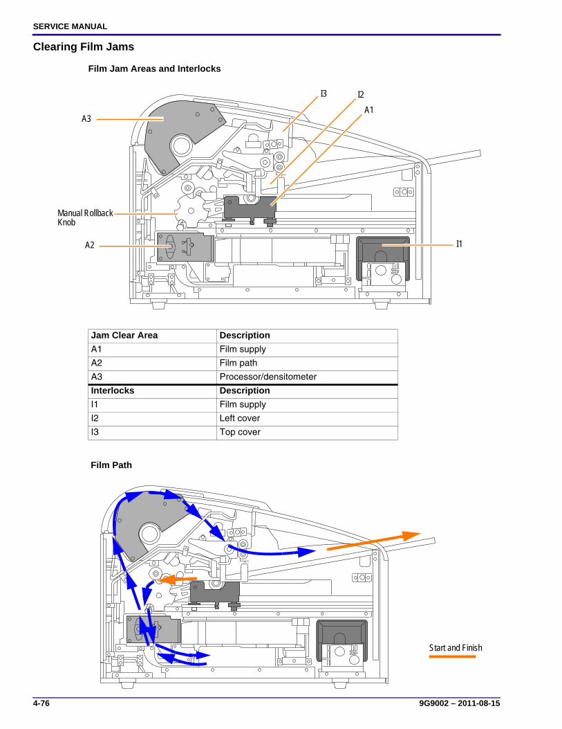
SERVICE MANUAL
4-76 9G9002 – 2011-08-15
Clearing Film Jams
Film Jam Areas and Interlocks
Film Path
Jam Clear Area Description
A1 Film supply
A2 Film path
A3 Processor/densitometer
Interlocks Description
I1 Film supply
I2 Left cover
I3 Top cover
A1
A2
A3
Manual Rollback Knob
I3 I2
I1
Start and Finish

Diagnostics
9G9002 – 2011-08-15 4-77
Sensors
Sensor Description
S1 Film cartridge
S2 Rollback home
S3 Pickup home
S4 Film contact (Pickup)
S5 Feed roller open
S6 Start of Page (SOP - Exposure Transport)
S7 Densitometer
S6
S1
S2
S5S4
S3
S7
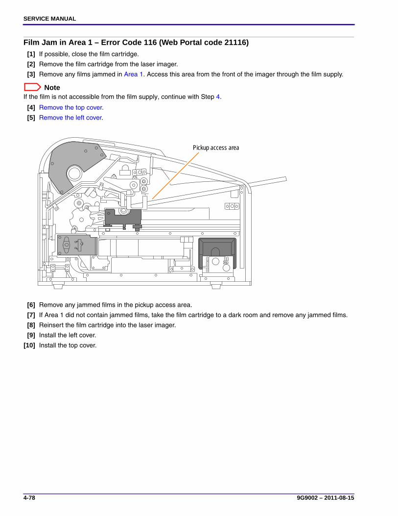
SERVICE MANUAL
4-78 9G9002 – 2011-08-15
Film Jam in Area 1 – Error Code 116 (Web Portal code 21116)[1] If possible, close the film cartridge.
[2] Remove the film cartridge from the laser imager.
[3] Remove any films jammed in Area 1. Access this area from the front of the imager through the film supply.
NoteIf the film is not accessible from the film supply, continue with Step 4.
[4] Remove the top cover.
[5] Remove the left cover.
[6] Remove any jammed films in the pickup access area.
[7] If Area 1 did not contain jammed films, take the film cartridge to a dark room and remove any jammed films.
[8] Reinsert the film cartridge into the laser imager.
[9] Install the left cover.
[10] Install the top cover.
Pickup access area
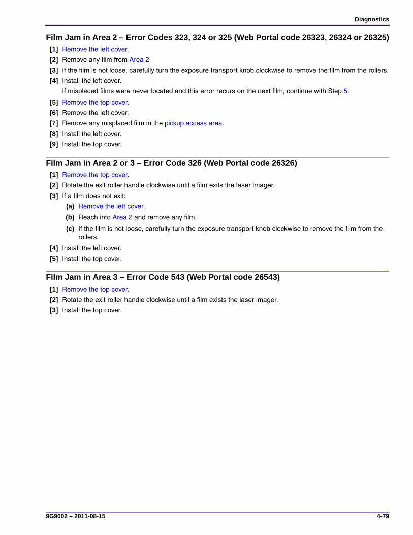
Diagnostics
9G9002 – 2011-08-15 4-79
Film Jam in Area 2 – Error Codes 323, 324 or 325 (Web Portal code 26323, 26324 or 26325)[1] Remove the left cover.
[2] Remove any film from Area 2.
[3] If the film is not loose, carefully turn the exposure transport knob clockwise to remove the film from the rollers.
[4] Install the left cover.
If misplaced films were never located and this error recurs on the next film, continue with Step 5.
[5] Remove the top cover.
[6] Remove the left cover.
[7] Remove any misplaced film in the pickup access area.
[8] Install the left cover.
[9] Install the top cover.
Film Jam in Area 2 or 3 – Error Code 326 (Web Portal code 26326)[1] Remove the top cover.
[2] Rotate the exit roller handle clockwise until a film exits the laser imager.
[3] If a film does not exit:
(a) Remove the left cover.
(b) Reach into Area 2 and remove any film.
(c) If the film is not loose, carefully turn the exposure transport knob clockwise to remove the film from the rollers.
[4] Install the left cover.
[5] Install the top cover.
Film Jam in Area 3 – Error Code 543 (Web Portal code 26543)[1] Remove the top cover.
[2] Rotate the exit roller handle clockwise until a film exists the laser imager.
[3] Install the top cover.

SERVICE MANUAL
4-80 9G9002 – 2011-08-15
Functions of the MCS Board Test Points, Jumpers, and Switches
Machine Control System (MCS) Board
LEDs, Jumpers, and Switches
Item Function Status
LED1 Config Off = normal (On for a short time after reset)
LED2 Heater on Blinking = normal
LED3 CPU “OK” Blinking = normal
LED4 Interlocks satisfied On = all interlocks closed
LED5* Cartridge detect • Off = Cartridge detected
• On = No cartridge
LED6* Pickup home On = pickup at home position
LED7* Film contact • Off = sensor actuated by film (detected)
• On = sensor did not detect any film
LED8* Nip home On = film transport nip roller at home position
LED9* SOP Blinks briefly when film is first detected by SOP sensor.Does not stay in steady state.
LED10* Rollback open Not used
LED11* Rollback closed On = rollback at home position
LED12 Spare 1 Not used
LED13 Spare 2 Not used
LED14* Armed On = hardware is ready to lay down pixels on film when SOP sensor triggers it
LED15* Expose On = laser is on
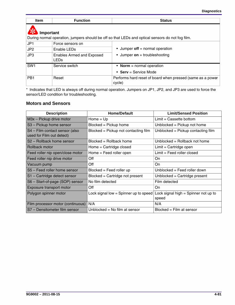
Diagnostics
9G9002 – 2011-08-15 4-81
Motors and Sensors
ImportantDuring normal operation, jumpers should be off so that LEDs and optical sensors do not fog film.
JP1 Force sensors on• Jumper off = normal operation
• Jumper on = troubleshooting
JP2 Enable LEDs
JP3 Enables Armed and Exposed LEDs
SW1 Service switch • Norm = normal operation
• Serv = Service Mode
PB1 Reset Performs hard reset of board when pressed (same as a power cycle)
* Indicates that LED is always off during normal operation. Jumpers on JP1, JP2, and JP3 are used to force the sensor/LED condition for troubleshooting.
Description Home/Default Limit/Sensed Position
M3x – Pickup drive motor Home = Up Limit = Cassette bottom
S3 – Pickup home sensor Blocked = Pickup home Unblocked = Pickup not home
S4 – Film contact sensor (also used for Film out detect)
Blocked = Pickup not contacting film Unblocked = Pickup contacting film
S2 – Rollback home sensor Blocked = Rollback home Unblocked = Rollback not home
Rollback motor Home = Cartridge closed Limit = Cartridge open
Feed roller nip open/close motor Home = Feed roller open Limit = Feed roller closed
Feed roller nip drive motor Off On
Vacuum pump Off On
S5 – Feed roller home sensor Blocked = Feed roller up Unblocked = Feed roller down
S1 – Cartridge detect sensor Blocked = Cartridge not present Unblocked = Cartridge present
S6 – Start-of-page (SOP) sensor No film detected Film detected
Exposure transport motor Off On
Polygon spinner motor Lock signal low = Spinner up to speed Lock signal high = Spinner not up to speed
Film processor motor (continuous) N/A N/A
S7 – Densitometer film sensor Unblocked = No film at sensor Blocked = Film at sensor
Item Function Status
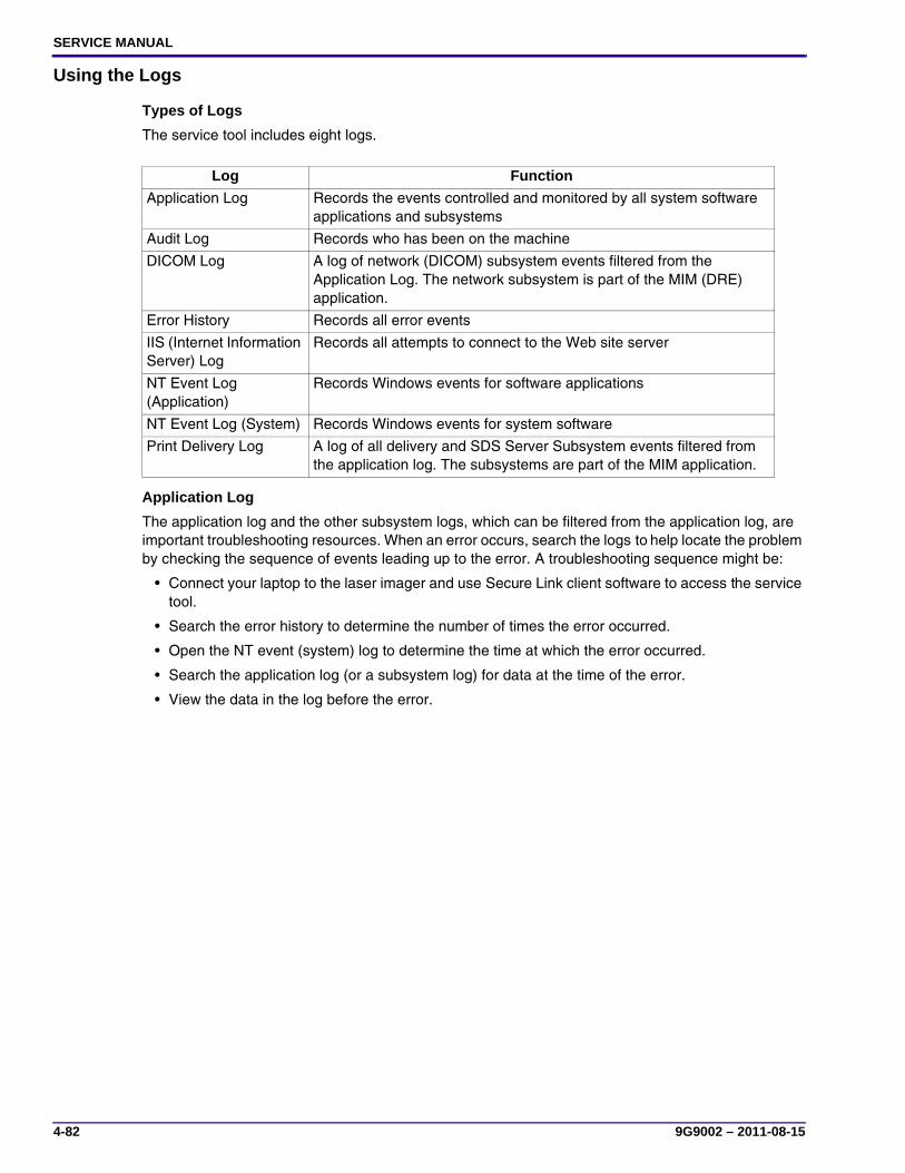
SERVICE MANUAL
4-82 9G9002 – 2011-08-15
Using the Logs
Types of Logs
The service tool includes eight logs.
Application Log
The application log and the other subsystem logs, which can be filtered from the application log, are important troubleshooting resources. When an error occurs, search the logs to help locate the problem by checking the sequence of events leading up to the error. A troubleshooting sequence might be:
• Connect your laptop to the laser imager and use Secure Link client software to access the service tool.
• Search the error history to determine the number of times the error occurred.
• Open the NT event (system) log to determine the time at which the error occurred.
• Search the application log (or a subsystem log) for data at the time of the error.
• View the data in the log before the error.
Log Function
Application Log Records the events controlled and monitored by all system software applications and subsystems
Audit Log Records who has been on the machine
DICOM Log A log of network (DICOM) subsystem events filtered from the Application Log. The network subsystem is part of the MIM (DRE) application.
Error History Records all error events
IIS (Internet Information Server) Log
Records all attempts to connect to the Web site server
NT Event Log (Application)
Records Windows events for software applications
NT Event Log (System) Records Windows events for system software
Print Delivery Log A log of all delivery and SDS Server Subsystem events filtered from the application log. The subsystems are part of the MIM application.

Diagnostics
9G9002 – 2011-08-15 4-83
Accessing the Application Log[1] Select Logs > Application Log from the main menu of the service tool. A blank log screen with a Log Retrieval
window is displayed.
[2] Use the Log Retrieval window to locate the log data to view:
• If you know the approximate time when the event occurred, select View Log With Time Range and enter a Start and End Time.
• To view the log of an event when the event is occurring, select View Active Log.
[3] Click OK. The retrieved log displays.
[4] Click Options to display a screen of the columns of the log.
You can use this screen to choose the data fields you want to view or decrease the width of the log.
[5] To decrease the log to a usable width, clear the check boxes of the columns in the display field that you do not want to view.
NoteYou can also decrease or increase the column width in the log by clicking the lines between the columns and dragging the column left or right.
[6] Click OK.

SERVICE MANUAL
4-84 9G9002 – 2011-08-15
Log Keying Functions
NoteYour computer must have Log Viewer software to view the logs.
Button Function
Start Displays parameters for retrieving a new log. The Log Retrieval screen displays.
• If you know the approximate time when an error occurred:
1. Select View Log With Time Range.
2. Type a Start Time and an End Time.
3. Click OK.
• To view the log during the time an event occurs:
1. Select View Active Log.
2. Click OK.
Stop Stop the loading process while a log is loading
Load Loads a log from a saved .xml or .KFC-log file on your computer
Save Saves a log to a folder to your computer
? Opens the Help screen
Options Displays a screen of the log columns available for viewing1. Select the name of each column you want to view in the log.
2. Click OK to display the log.
Find Searches for a string in the log that you can identify by words or numbers, for example, a condition code
Find Next Locates the next instance of the string that you entered from the Find operation
Display Filter Filters the log to decrease the amount of log data for analytical use. (See “Using Filtering”)
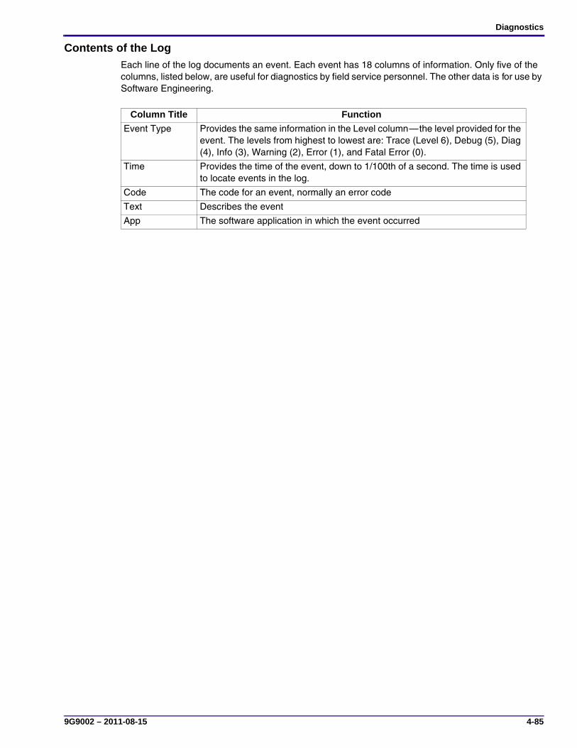
Diagnostics
9G9002 – 2011-08-15 4-85
Contents of the LogEach line of the log documents an event. Each event has 18 columns of information. Only five of the columns, listed below, are useful for diagnostics by field service personnel. The other data is for use by Software Engineering.
Column Title Function
Event Type Provides the same information in the Level column—the level provided for the event. The levels from highest to lowest are: Trace (Level 6), Debug (5), Diag (4), Info (3), Warning (2), Error (1), and Fatal Error (0).
Time Provides the time of the event, down to 1/100th of a second. The time is used to locate events in the log.
Code The code for an event, normally an error code
Text Describes the event
App The software application in which the event occurred
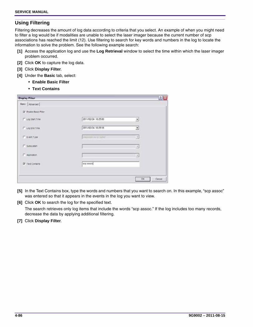
SERVICE MANUAL
4-86 9G9002 – 2011-08-15
Using FilteringFiltering decreases the amount of log data according to criteria that you select. An example of when you might need to filter a log would be if modalities are unable to select the laser imager because the current number of scp associations has reached the limit (12). Use filtering to search for key words and numbers in the log to locate the information to solve the problem. See the following example search:
[1] Access the application log and use the Log Retrieval window to select the time within which the laser imager problem occurred.
[2] Click OK to capture the log data.
[3] Click Display Filter.
[4] Under the Basic tab, select:
• Enable Basic Filter
• Text Contains
[5] In the Text Contains box, type the words and numbers that you want to search on. In this example, “scp assoc” was entered so that it appears in the events in the log you want to view.
[6] Click OK to search the log for the specified text.
The search retrieves only log items that include the words “scp assoc.” If the log includes too many records, decrease the data by applying additional filtering.
[7] Click Display Filter.

Diagnostics
9G9002 – 2011-08-15 4-87
[8] Click the Advanced tab.
[9] Select Enable Advanced Filter. This adds the filter criteria to the original search words “scp assoc”.
(a) Select Time in the Field drop-down list (scroll the list).
(b) Select Text in the As drop-down list.
(c) Narrow the time period by selecting the appropriate parameter in the next drop-down list, and then type the date and time in the box. Use yyyy/mm/dd[space][space]hh:mm format, with hours in 24-hour time.
[10] Click OK to retrieve all the “scp association” events during the time selected.
[11] Open the Advanced filter again and add criteria to show only the events where the Text field contained “down.”
The log is filtered to show scp associations that went down during the specified time period.

SERVICE MANUAL
4-88 9G9002 – 2011-08-15
Changing Log Levels
ImportantLevels higher than the recommended defaults can slow down the system. If you change a level to help diagnose a problem, return the level to the default value after completing troubleshooting.
The level recorded in the logs for each subsystem can be changed, if necessary, for troubleshooting purposes. To change log levels for subsystems:
[1] From the service tool, select Configuration > System > Log Level.
[2] Click Modify.
[3] From the drop-down list for the each subsystem, select the log level you want, and then click Save.
The log levels, from highest to lowest, are:
Fatal Error: Record only fatal errors.
Error: Record all errors.
Warning: Record warnings and all errors.
Information: Record key events.
Diagnostic: Provide a level of information for field troubleshooting.
Debug: Provide a level of information for software debugging.
Trace: Records all communication in use for any subsystems

Illustrated Parts List
9G9002 – 2011-08-15 5-1
Section 5: Illustrated Parts List
Main AssemblyFigure 1 Main Assembly – Front view
H221_6054DCH221_6054DCA
1
5
23
17
4
10
1314
161512
2021
25
2827
3736
18
8 9
76
19
24
3031
32
33
34
11
2 3
35
26
22
29
1 2 3
6
7
8 9
10
12
13
14 15
16
17
18 19
2021
22
2324
25
26
2728
29
3031
32
3335
3637
4 5
11
34

SERVICE MANUAL
5-2 9G9002 – 2011-08-15
Figure 1 Main Assembly – Front view
Item Part No. Part Name 1 Quantity Detailed Description1 A4A99G0893 Screw 1 15 Screw - machine; M3 × 10 mm L, steel, ZPCC2 A4A99G5248 Assembly - Cooling and
densitometer 1
1 Assembly: Processor coolingand densitometer
3 A4A99G5649 Assembly - Heat sink 1 1 Assembly: Heat sink - processor4 A4A99G0093 Manifold - Exhaust 1 1 Assembly: Exhaust - cooling, processor5 A4A99G3970 Gasket - drum cover 1 1 Gasket - drum cover, processor6 A4A99G3271 Gear - drive 1 2 Gear - drive, feed roller7 A4A99G4017 Gear - worm 1 1 Gear - worm, 20 tooth, transport; RoHS compliant8 A4A95F0907 Retaining ring 1 1 Retaining ring - external; 4.0–5.0 mm shaft dia.,
0.6 mm T, carbon steel, Trivalent Zinc Plus sealer9 A4A95F4586 Retaining ring 1 7 Retaining ring - external; 6.0–8.0 mm shaft dia.,
0.7 mm T, carbon steel, Trivalent Zinc Plus sealer; RoHS compliant
10 A4A98F3170 Motor - stepper 1 1 Motor - stepper, DC11 A4A99G4093 Insulation - end plate,
right 1
1 Insulation - end plate, right, processor; RoHS compliant
12 A4A95F1875 Nut 1 2 Nut - machine; Keps, steel class 6/8, plain zinc, M4 × 0.7 mm; RoHS compliant
13 A4A97F2484 Pulley 1 1 Pulley - transport; 3 mm, GT, 16 groove14 A4A99G1676 Belt - timing 1 1 Belt - timing; 6 mm W, 48 tooth, 144 mm L × 3 mm
W pitch15 A4A95F4586 Retaining ring 1 7 Retaining ring- external; 6.0–8.0 mm shaft dia.,
0.7 mm T, carbon steel, Trivalent Zinc Plus sealer; RoHS compliant
16 A4A99G4605 Pulley 1 1 Pulley- transport; 3 mm, 16 tooth, GT, machined; RoHS compliant
17 A4A95F4586 Retaining ring 1 7 Retaining ring - external; 6.0–8.0 mm shaft dia., 0.7 mm T, carbon steel, Trivalent Zinc Plus sealer; RoHS compliant
18 A4A99G5064 Screw 1 2 Screw - machine; SEMS, pan head, Torx T10, M3 × 0.5 × 6, clear zinc
19 A4A92G1630 Motor - stepper 1 1 Motor - stepper, processor drive20 A4A99G1675 Timing belt 1 1 Belt - timing; 6 mm W, double-sided, 232 tooth,
696 mm L × 3 mm W pitch21 A4A97F2485 Pulley 1 1 Pulley - transport; 3 mm, 24 groove, GT; RoHS
compliant22 A4A99G6356 Spring - extension 1 2 Spring - extension; 0.018 in. wire diameter ×
2.750 in. L, stainless steel23 A4A99G0894 Screw 1 2 Screw - machine; SEMS, pan head, Torx T20, M4 ×
0.7 mm × 8.0 mm, clear zinc24 A4A97E8211 Chain 1 1 Chain; MicroTrak 0130 series, cable carrier system,
fiber reinforced nylon, flexible, black, 17 links, 1 set of brackets, 20 mm bend radius
25 A4A99G0895 Screw 1 4 Screw - machine; SEMS, pan head, Torx T20, M4 × 0.7 × 16, clear zinc
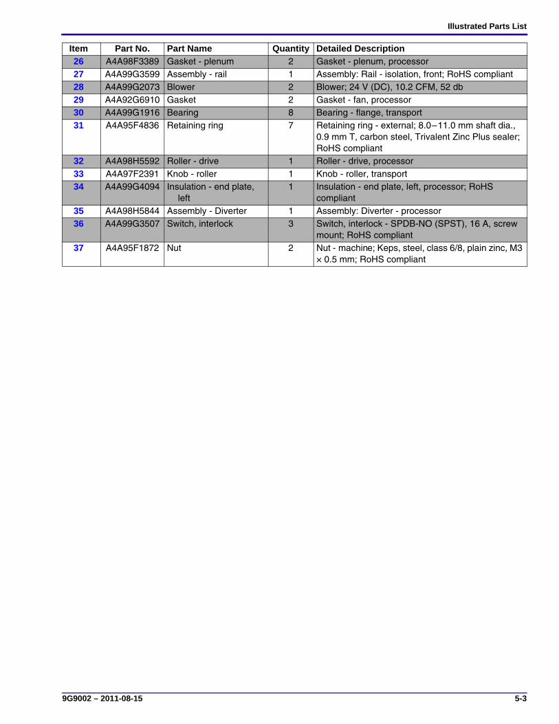
Illustrated Parts List
9G9002 – 2011-08-15 5-3
26 A4A98F3389 Gasket - plenum 1 2 Gasket - plenum, processor27 A4A99G3599 Assembly - rail 1 1 Assembly: Rail - isolation, front; RoHS compliant28 A4A99G2073 Blower 1 2 Blower; 24 V (DC), 10.2 CFM, 52 db29 A4A92G6910 Gasket 1 2 Gasket - fan, processor30 A4A99G1916 Bearing 1 8 Bearing - flange, transport31 A4A95F4836 Retaining ring 1 7 Retaining ring - external; 8.0–11.0 mm shaft dia.,
0.9 mm T, carbon steel, Trivalent Zinc Plus sealer; RoHS compliant
32 A4A98H5592 Roller - drive 1 1 Roller - drive, processor33 A4A97F2391 Knob - roller 1 1 Knob - roller, transport34 A4A99G4094 Insulation - end plate,
left 1
1 Insulation - end plate, left, processor; RoHS compliant
35 A4A98H5844 Assembly - Diverter 1 1 Assembly: Diverter - processor36 A4A99G3507 Switch, interlock 1 3 Switch, interlock - SPDB-NO (SPST), 16 A, screw
mount; RoHS compliant37 A4A95F1872 Nut 1 2 Nut - machine; Keps, steel, class 6/8, plain zinc, M3
× 0.5 mm; RoHS compliant
Item Part No. Part Name 1 Quantity Detailed Description

SERVICE MANUAL
5-4 9G9002 – 2011-08-15
Figure 2 Main Assembly – Rear view
H221_6055DCH221_6055DCA
2
1
34
10
12
9
87
11
56
1
2
34
56
78
1011
12
9

Illustrated Parts List
9G9002 – 2011-08-15 5-5
Figure 2 Main Assembly – Rear view
Item Part No. Part Name 2 Quantity Detailed Description1 A4A98E4053 Switch 2 1 Switch - optical, emitter/sensor, interruptive;
Schmitt Trigger w/flag, 5.0 V (DC), Molex 5102 series connector. 0.2 in. W slot; RoHS compliant
2 A4A99G1143 Lock 2 1 Lock - shipping, rear, right3 A4A95E5849 Switch 2 1 Switch - rocker, mechanical; single unit, alternate
action, non-illuminated, snap-in mounting, panel mount, DPST, 250 V (AC), 20 A, 6.3 in. × 0.8 in.
4 26-1004-3199-3 Circuit breaker 2 2 Circuit breaker; single pole, 15 A @ 32 V (DC)/250 V (AC), black bezel, black button, through-hole
5 A4A99G0777 Power supply 2 1 Power supply - switching, single; 24 V, 65 W; RoHS compliant
6 A4A95F7220 Pump 2 1 Pump - compressor/vacuum; through-hole, 0.125 in. barb, EPDM valves, 24 V (DC), 22.5 psi
7 A4A99G1618 Lock 2 1 Lock - shipping, rear, lt8 A4A99H0680 Screw 2 10 Screw - machine; hex washer head, M4 × 8 mm L,
steel, ZPCC; RoHS compliant9 A4A99G2723 Gasket - horizontal, back
panel 2
1 Gasket - horizontal, back panel; RoHS compliant
10 A4A99G1142 Rail - isolation 2 1 Rail - isolation, floating, rear11 A4A95F9624 Spring 2 2 Spring, compression - 0.97 in. OD × 0.08 wire dia.,
1.00 free length; RoHS compliant12 A4A92G0068 Damper - foam 2 2 Damper - foam, isolation; RoHS compliant

SERVICE MANUAL
5-6 9G9002 – 2011-08-15
Cables and HarnessesFigure 3 Cables and Harnesses
H221_6056DCH221_6056DCA
12
3
4
5
6
7
8
910
11
12
13
14
1516
12
3
4
5
6
7
8
9
10
11
12
13
14
1516

Illustrated Parts List
9G9002 – 2011-08-15 5-7
Figure 3 Cables and Harnesses
Item Part No. Part Name 3 Quantity Detailed Description1 A4A99G3453 Cable 3 1 Cable - MCS to service, ethernet; RoHS compliant2 A4A99G0724 Cable 3 1 Cable - MCS to DRE; RoHS compliant3 A4A99G0716 Cable 3 1 Cable - MCS to DRE, ethernet; RoHS compliant4 A4A99G0721 Harness 3 1 Harness - MCS to slip ring, intermediate; RoHS compliant5 A4A99G2642 Cable 3 1 Cable - DRE to bulkhead, ethernet; RoHS compliant6 A4A99G0718 Harness 3 1 Harness - MCS to transport; RoHS compliant7 A4A99G0727 Harness 3 1 Harness - MCS to rollback; RoHS compliant8 A4A99G0720 Cable 3 1 Cable - MCS to processor motor; RoHS compliant9 A4A99G0728 Harness 3 1 Harness - power switch to MCS/power supply; RoHS compliant
10 A4A99G3397 Harness 3 1 Harness - MCS to pickup, intermediate; RoHS compliant11 A4A99G0725 Cable 3 1 Cable - MCS to power supply; RoHS compliant12 A4A99G3002 Harness 3 1 Harness - MCS to faz fans, intermediate; RoHS compliant13 A4A99G0723 Cable 3 1 Cable - MCS to RF tag, RoHS compliant14 A4A99G0714 Harness 3 1 Harness - MCS to densitometer; RoHS compliant15 A4A99G0726 Harness 3 1 Harness - MCS to interlocks; RoHS compliant16 A4A99G0715 Cable 3 1 Cable - MCS to local panel; RoHS compliant

SERVICE MANUAL
5-8 9G9002 – 2011-08-15
CoversFigure 4 Covers
H221_6053DCH221_6053DCA
6
10
1
3
8
5
4
13
7
16 15
2
14
9
11 12
1
2
3
5
6
7
8
9
10
11 12
13
141516
4
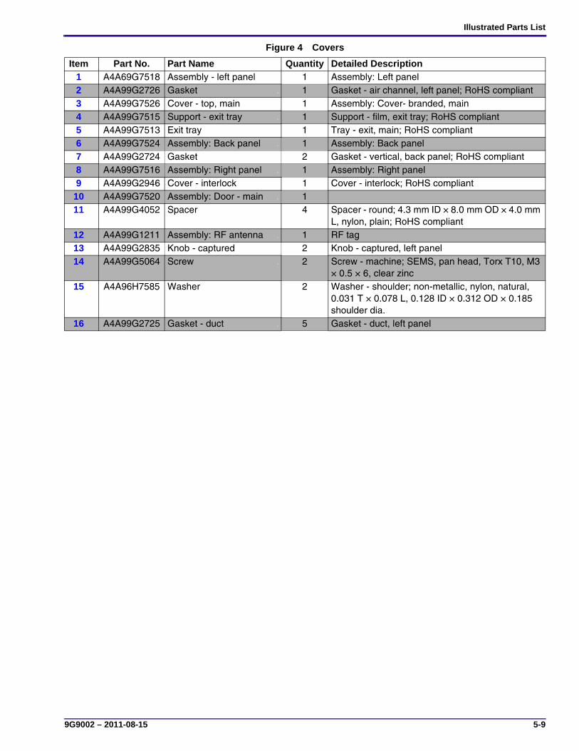
Illustrated Parts List
9G9002 – 2011-08-15 5-9
Figure 4 Covers
Item Part No. Part Name 4 Quantity Detailed Description1 A4A69G7518 Assembly - left panel 4 1 Assembly: Left panel2 A4A99G2726 Gasket 4 1 Gasket - air channel, left panel; RoHS compliant3 A4A99G7526 Cover - top, main 4 1 Assembly: Cover- branded, main4 A4A99G7515 Support - exit tray 4 1 Support - film, exit tray; RoHS compliant5 A4A99G7513 Exit tray 4 1 Tray - exit, main; RoHS compliant6 A4A99G7524 Assembly: Back panel 4 1 Assembly: Back panel7 A4A99G2724 Gasket 4 2 Gasket - vertical, back panel; RoHS compliant8 A4A99G7516 Assembly: Right panel 4 1 Assembly: Right panel9 A4A99G2946 Cover - interlock 4 1 Cover - interlock; RoHS compliant
10 A4A99G7520 Assembly: Door - main 4 111 A4A99G4052 Spacer 4 4 Spacer - round; 4.3 mm ID × 8.0 mm OD × 4.0 mm
L, nylon, plain; RoHS compliant12 A4A99G1211 Assembly: RF antenna 4 1 RF tag13 A4A99G2835 Knob - captured 4 2 Knob - captured, left panel14 A4A99G5064 Screw 4 2 Screw - machine; SEMS, pan head, Torx T10, M3
× 0.5 × 6, clear zinc15 A4A96H7585 Washer 4 2 Washer - shoulder; non-metallic, nylon, natural,
0.031 T × 0.078 L, 0.128 ID × 0.312 OD × 0.185 shoulder dia.
16 A4A99G2725 Gasket - duct 4 5 Gasket - duct, left panel
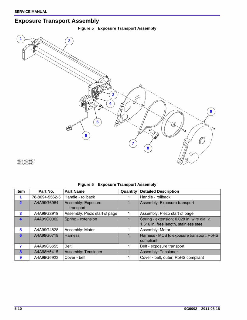
SERVICE MANUAL
5-10 9G9002 – 2011-08-15
Exposure Transport AssemblyFigure 5 Exposure Transport Assembly
Figure 5 Exposure Transport Assembly
Item Part No. Part Name 5 Quantity Detailed Description1 78-8094-5562-5 Handle - rollback 5 1 Handle - rollback2 A4A99G6964 Assembly: Exposure
transport 5
1 Assembly: Exposure transport
3 A4A99G2919 Assembly: Piezo start of page5 1 Assembly: Piezo start of page4 A4A99G0062 Spring - extension 5 1 Spring - extension; 0.028 in. wire dia. ×
1.516 in. free length, stainless steel5 A4A99G4828 Assembly: Motor 5 1 Assembly: Motor6 A4A99G0719 Harness 5 1 Harness - MCS to exposure transport; RoHS
compliant7 A4A99G3655 Belt 5 1 Belt - exposure transport8 A4A98H5415 Assembly: Tensioner 5 1 Assembly: Tensioner9 A4A99G6923 Cover - belt 5 1 Cover - belt, outer; RoHS compliant
H221_6038HC
9
87
6
5
4
3
21
H221_6038HCA
1 2
3
4
5
6
78
9
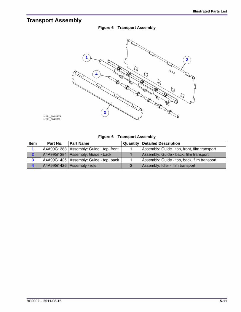
Illustrated Parts List
9G9002 – 2011-08-15 5-11
Transport AssemblyFigure 6 Transport Assembly
Figure 6 Transport Assembly
Item Part No. Part Name 6 Quantity Detailed Description1 A4A99G1383 Assembly: Guide - top, front 6 1 Assembly: Guide - top, front, film transport2 A4A99G1284 Assembly: Guide - back 6 1 Assembly: Guide - back, film transport3 A4A99G1425 Assembly: Guide - top, back 6 1 Assembly: Guide - top, back, film transport4 A4A99G1426 Assembly - idler 6 2 Assembly: Idler - film transport
H221_6041BCH221_6041BCA
21
3
4
1 2
3
4

SERVICE MANUAL
5-12 9G9002 – 2011-08-15
Pickup AssemblyFigure 7 Pickup Assembly
H221_6046DC
16
5
2
H221_6046DCA
3
4
6
7
8
9
1011
12
14
15
17
18
19
20
2122
13
11
2
3
45
6
7
8
9
1011
12
1314
15
16
17
18
19
20
2122
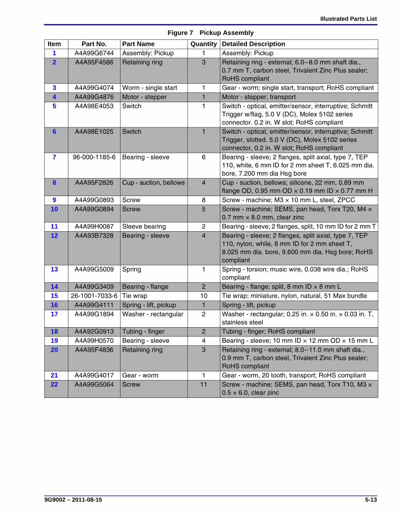
Illustrated Parts List
9G9002 – 2011-08-15 5-13
Figure 7 Pickup Assembly
Item Part No. Part Name 7 Quantity Detailed Description1 A4A99G6744 Assembly: Pickup 7 1 Assembly: Pickup2 A4A95F4586 Retaining ring 7 3 Retaining ring - external; 6.0–8.0 mm shaft dia.,
0.7 mm T, carbon steel, Trivalent Zinc Plus sealer; RoHS compliant
3 A4A99G4074 Worm - single start 7 1 Gear - worm; single start, transport; RoHS compliant4 A4A99G4876 Motor - stepper 7 1 Motor - stepper, transport5 A4A98E4053 Switch 7 1 Switch - optical, emitter/sensor, interruptive; Schmitt
Trigger w/flag, 5.0 V (DC), Molex 5102 series connector. 0.2 in. W slot; RoHS compliant
6 A4A98E1025 Switch 7 1 Switch - optical, emitter/sensor, interruptive; Schmitt Trigger, slotted. 5.0 V (DC), Molex 5102 series connector, 0.2 in. W slot; RoHS compliant
7 96-000-1185-6 Bearing - sleeve 7 6 Bearing - sleeve; 2 flanges, split axial, type 7, TEP 110, white, 6 mm ID for 2 mm sheet T, 6.025 mm dia. bore, 7.200 mm dia Hsg bore
8 A4A95F2826 Cup - suction, bellows7 4 Cup - suction, bellows; silicone, 22 mm, 0.89 mm flange OD, 0.95 mm OD × 0.19 mm ID × 0.77 mm H
9 A4A99G0893 Screw 7 8 Screw - machine; M3 × 10 mm L, steel, ZPCC10 A4A99G0894 Screw 7 5 Screw - machine; SEMS, pan head, Torx T20, M4 ×
0.7 mm × 8.0 mm, clear zinc11 A4A99H0087 Sleeve bearing 7 2 Bearing - sleeve; 2 flanges, split, 10 mm ID for 2 mm T12 A4A93B7328 Bearing - sleeve 7 4 Bearing - sleeve; 2 flanges, split axial, type 7, TEP
110, nylon, while, 8 mm ID for 2 mm sheet T, 8.025 mm dia. bore, 9.600 mm dia. Hsg bore; RoHS compliant
13 A4A99G5009 Spring 7 1 Spring - torsion; music wire, 0.038 wire dia.; RoHS compliant
14 A4A99G3409 Bearing - flange 7 2 Bearing - flange; split, 8 mm ID × 8 mm L15 26-1001-7033-6 Tie wrap 7 10 Tie wrap; miniature, nylon, natural, 51 Max bundle16 A4A99G4111 Spring - lift, pickup 7 1 Spring - lift, pickup17 A4A99G1894 Washer - rectangular 7 2 Washer - rectangular; 0.25 in. × 0.50 in. × 0.03 in. T,
stainless steel18 A4A92G0913 Tubing - finger 7 2 Tubing - finger; RoHS compliant19 A4A99H0570 Bearing - sleeve 7 4 Bearing - sleeve; 10 mm ID × 12 mm OD × 15 mm L20 A4A95F4836 Retaining ring 7 3 Retaining ring - external; 8.0–11.0 mm shaft dia.,
0.9 mm T, carbon steel, Trivalent Zinc Plus sealer; RoHS compliant
21 A4A99G4017 Gear - worm 7 1 Gear - worm, 20 tooth, transport; RoHS compliant22 A4A99G5064 Screw 7 11 Screw - machine; SEMS, pan head, Torx T10, M3 ×
0.5 × 6.0, clear zinc

SERVICE MANUAL
5-14 9G9002 – 2011-08-15
Feed Roller AssemblyFigure 8 Feed Roller Assembly
Figure 8 Feed Roller Assembly
Item Part No. Part Name 8 Quantity Detailed Description1 A4A99G3747 Assembly - link, left 8 1 Assembly: Link, left, feed roller2 A4A95F4586 Retaining ring 8 1 Retaining ring - external; 6.0–8.0 mm shaft dia., 0.7 mm
T, carbon steel, Trivalent Zinc Plus sealer; RoHS compliant
3 A4A99G4074 Worm - single start 8 1 Gear - worm; single start, transport; RoHS compliant4 A4A99G5064 Screw 8 4 Screw - machine; SEMS, pan head, Torx T10, M3 × 0.5
× 6.0, clear zinc5 A4A99G4876 Motor - stepper 8 1 Motor - stepper, transport6 A4A98E1025 Switch 8 2 Switch - optical, emitter/sensor, interruptive; Schmitt
Trigger, slotted. 5.0 V (DC), Molex 5102 series connector, 0.2 in. W slot; RoHS compliant
7 A4A99G3353 Assembly - link, right 8 1 Assembly: Link, right, feed roller8 A4A99G1480 Flag - sensor 8 1 Flag - sensor, feed roller9 A4A99G4017 Gear - worm 8 1 Gear - worm; 20 tooth, transport10 A4A99G3271 Gear - drive 8 1 Gear - drive, feed roller
H221_6047HCH221_6047HCA
5
7
6
4
3
2
1
89
10
10
1
2
3
4
5
6
7
89
10
10

Illustrated Parts List
9G9002 – 2011-08-15 5-15
Processor Drum AssemblyFigure 9 Processor Drum Assembly
Figure 9 Processor Drum Assembly
Item Part No. Part Name 9 Quantity Detailed Description1 A4A99G6749 Assembly - cover 9 1 Assembly: Cover - processor2 A4AA9G6746 Assembly - drum, 120 V9 1 Assembly: Drum - processor; 120 V; RoHS compliant3 A4A99G6748 Assembly - drum, 240 V9 1 Assembly: Drum - processor; 240 V; RoHS compliant4 A4A99G0195 Insulation drum - back 9 1 Insulation - drum, back, processor5 A4A99G4093 Insulation - end plate,
right 9
1 Insulation - end plate, right, processor; RoHS compliant
6 A4A99G0027 Insulation - drum, front 9 1 Insulation - drum, front, processor7 A4A99G4094 Insulation - end plate,
left 9
1 Insulation - end plate, left, processor; RoHS compliant
8 A4A99G5248 Assembly - Cooling and densitometer 9
1 Assembly: Processor coolingand densitometer
9 A4A99G5904 Assembly - pad 9 1 Assembly: Pad - processor10 A4A99G5649 Assembly - heat sink 9 1 Assembly: Heat sink - processor
H221_6057DCH221_6057DCA
1
4
5
6
7
9
2, 3
8
1
8
9
10
46
2 3
5
7

SERVICE MANUAL
5-16 9G9002 – 2011-08-15
Imaging AssemblyFigure 10 Imaging Assembly
Figure 10 Imaging Assembly
Item Part No. Part Name 10 Quantity Detailed Description1 A4A99G6742 Assembly - optics 10 1 Assembly: Optics; RoHS compliant2 A4A99G6964 Assembly: Exposure transport 10 1 Assembly: Exposure transport
H221_6048DCH221_6048DCA
2
11
2

Illustrated Parts List
9G9002 – 2011-08-15 5-17
Local Panel (Display Screen) AssemblyFigure 11 Local Panel (Display Screen) Assembly
Figure 11 Local Panel (Display Screen) Assembly
Item Part No. Part Name 11 Quantity Detailed Description1 A4A99G1217 Assembly - local panel 11 1 Assembly: Local panel; RoHS compliant
H221_6049HC
1
H221_6039HCA
1

SERVICE MANUAL
5-18 9G9002 – 2011-08-15
Electronics AssemblyFigure 12 Electronics Assembly
Figure 12 Electronics Assembly
Item Part No. Part Name 12 Quantity Detailed Description1 A4A99G0249 Assembly: MCS 12 1 Assembly: MCS2 A4A99G4842 Assembly - Compact flash 12 1 Compact flash; CF 4, MLC, 4 GB3 A4A99G4716 Assembly - motherboard 12 1 Assembly: Motherboard - DRE, programmed;
RoHS compliant
H221_6044HCH221_6044HCA
2
13
1
2
3

Illustrated Parts List
9G9002 – 2011-08-15 5-19
Rollback AssemblyFigure 13 Rollback Assembly
H221_6052HCH221_6052HCA
17 10
7
16
56
8
1312
1
3
15
4
14
9
11
2
1
2
3 45
67
8
9
10
11
12
1314
15
16
17

SERVICE MANUAL
5-20 9G9002 – 2011-08-15
Figure 13 Rollback Assembly
Item Part No. Part Name 13 Quantity Detailed Description1 A4A97H5747 Spring 13 2 Spring - extension; close wound, centered full loops, 2 lb./in.
stainless steel, 0.240 in OD × 0.029 in. wire dia. × 1.750 in. free L, 0.33 lb. initial tension, 3.47 extension W-O set
2 A4A98F2668 Knob 13 1 Knob - rollback3 A4A99H0087 Sleeve bearing 13 2 Bearing - sleeve; 2 flanges, split, 10 mm ID for 2 mm T4 A4A95F4836 Retaining ring 13 4 Retaining ring - external; 8.0–11.0 mm shaft dia., 0.9 mm T,
carbon steel, Trivalent Zinc Plus sealer; RoHS compliant5 A4A99G3660 Pulley 13 1 Pulley - reduction; 3 mm, GT, 50:166 A4A99G3576 Belt - timing 13 1 Belt - timing; 3 mm, 219 mm L × 6 mm W pitch, 73 teeth,
GT2; RoHS compliant7 A4A98F3211 Pulley 13 1 Pulley - processor; 3 mm, GT, 18 groove; RoHS compliant8 A4A99G1413 Flag - home 13 1 Flag - home, rollback9 A4A99G5064 Screw 13 6 Screw - machine; SEMS, pan head, Torx T10, M3 × 0.5 ×
6.0, clear zinc10 A4A92G1630 Motor - stepper 13 1 Motor - stepper, transport11 A4A99G0894 Screw 13 2 Screw - machine; SEMS, pan head, Torx T20, M4 × 0.7 mm
× 8.0 mm, clear zinc12 A4A95F4743 Belt - timing 13 1 Belt - timing; 3 mm, 201 mm L × 6 mm W pitch, 67 teeth,
GT2, neoprene, nylon, fiberglass; RoHS compliant13 A4A97F2484 Pulley 13 1 Pulley - transport; 3 mm, GT, 16 groove14 A4A95F4586 Retaining ring 13 3 Retaining ring - external; 6.0–8.0 mm shaft dia., 0.7 mm T,
carbon steel, Trivalent Zinc Plus sealer; RoHS compliant15 A4A93B7328 Bearing - sleeve 13 4 Bearing - sleeve; 2 flanges, split axial, type 7, TEP 110,
nylon, while, 8 mm ID for 2 mm sheet T, 8.025 mm dia. bore, 9.600 mm dia. Hsg bore; RoHS compliant
16 A4A99G2677 Shaft - wheel 13 4 Shaft - wheel, rollback17 A4A99G2014 Wheel - convex 13 4 Wheel - convex, rollback

Additional Service Procedures
9G9002 – 2011-08-15 6-1
Section 6: Additional Service Procedures
Accessing the Service Tool
Logging On to the Service Tool
Important• You must have the Secure Link Client Software, version 2.3 or higher and the Web Service Portal Software,
version 3.1.0.5 or higher installed and configured on your laptop computer.
• You will not be able to log on until 3 or 4 minutes after you have energized the laser imager.
[1] Connect the laptop computer to the laser imager (see Installation Instructions, “Connecting Your Computer to the Laser Imager”).
[2] Energize the laptop computer.
[3] Launch Secure Link from the Start menu.
[4] Type your password.
[5] Click OK.
[6] Type the IP address of the Service Port: 192.168.000.1.
[7] Check that the Port is set to 443.
[8] Click Connect.
[9] Launch the Web Service Portal Software (Web Portal) from the Start menu.
The main menu of the service tool displays.
Logging Off the Service Tool[1] In the right corner of the service tool, click Log Off.
[2] At the Web Portal screen, click Log Off.
[3] Close the Web Portal software.
[4] At the Secure Link screen:
(a) Click Disconnect.
(b) Close the screen.
[5] Disconnect the laptop computer from the laser imager.
[6] If you are finished with the service tool, install the right cover.

SERVICE MANUAL
6-2 9G9002 – 2011-08-15
Configuring the Laser Imager
ImportantYou must restart the laser imager from the service tool to permanently save configuration information.
Setting the Language
ImportantThe language is set by the customer in the Web Portal.
Checking the Values for the DICOM Source Communications[1] Connect the laptop computer to the laser imager (see Installation Instructions, “Connecting Your Computer to
the Laser Imager”).
[2] Select Configuration > DICOM SCP > Communications.
[3] Check:
• Port Number is 5040.
• Association Limit is 2.
[4] Are the values correct?
Yes No
Continue with “Setting the Laser Imager to be a Destination”.
a. Click Modify.
b. Type the correct values.
c. Click Save.
d. Continue with “Setting the Laser Imager to be a Destination”.

Additional Service Procedures
9G9002 – 2011-08-15 6-3
Setting the Laser Imager to be a Destination[1] Select Configuration > DICOM SCP > Destination.
ImportantThe AE Title is the name by which the modalities recognize the laser imager.
[2] Check with the customer to determine the AE Title to use.
[3] Click Modify.
[4] Type the selected AE Title in the window.
[5] Click the Media tab.
[6] In the Available column, select the check box next to the Media Type that will be used with the imager.
NoteUnder normal operations, all media types should be allowed.

SERVICE MANUAL
6-4 9G9002 – 2011-08-15
[7] Click the Page and Image Options tab, and then modify any settings according to customer demand.
ImportantDo not disable any of the page formatting settings of the laser imager except if instructed by the customer.
[8] Click Save.
[9] Continue with “Setting the System Clock”.
Setting the System Clock[1] Select Configuration > System > Clock.
ImportantThe system clock is set in the factory. At installation, the time zone has to be reset if the laser imager is installed in some other time zone. When you reset the time zone value, the time and date should display correctly.
[2] Will the clock be set manually or does the customer use a time server for synchronization?
[3] To correct the Time Zone value:
(a) Click Modify.
(b) If the Enable Time Synchronization check box is selected, clear it.
(c) Select the correct time zone from the Time Zone drop-down list.
(d) Click Save.
[4] Is the time value correct?
Manually Server
Continue with Step 3. a. Obtain the IP address of the server from the customer.
b. Perform Steps 16–23.
Yes No
Continue with Step 5. a. Click Modify.
b. In the Time boxes, type the hour and minute.
c. Click Save.
d. Continue with Step 5.
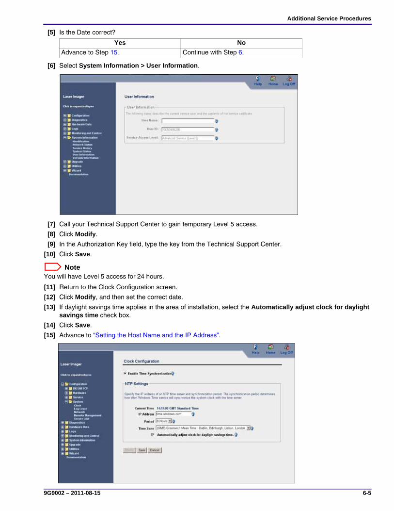
Additional Service Procedures
9G9002 – 2011-08-15 6-5
[5] Is the Date correct?
[6] Select System Information > User Information.
[7] Call your Technical Support Center to gain temporary Level 5 access.
[8] Click Modify.
[9] In the Authorization Key field, type the key from the Technical Support Center.
[10] Click Save.
NoteYou will have Level 5 access for 24 hours.
[11] Return to the Clock Configuration screen.
[12] Click Modify, and then set the correct date.
[13] If daylight savings time applies in the area of installation, select the Automatically adjust clock for daylight savings time check box.
[14] Click Save.
[15] Advance to “Setting the Host Name and the IP Address”.
Yes No
Advance to Step 15. Continue with Step 6.

SERVICE MANUAL
6-6 9G9002 – 2011-08-15
Perform the following steps if the customer uses a time server for synchronization.
[16] Click Modify.
[17] Select the Enable Time Synchronization check box.
[18] In the IP Address field, type the address of the time server to be used for synchronization.
[19] Select the synchronization period (how often the clock is synchronized) from the Period drop-down list.
[20] Select the correct time zone from the Time Zone drop-down list.
[21] If daylight savings time applies in the area of installation, select the Automatically adjust clock for daylight savings time check box.
[22] Click Save.
[23] Continue with “Setting the Host Name and the IP Address”.

Additional Service Procedures
9G9002 – 2011-08-15 6-7
Setting the Host Name and the IP Address[1] Obtain from the customer the host name, IP address, subnet, and gateway for the laser imager.
[2] Select Configuration > System > Network.
[3] Click Modify.
ImportantThe Host Name is the network name for this laser imager. It can be a maximum of 14 characters and a minimum of one. The first character must be a letter. Other characters can be a letter, a number, or a hyphen (-).
[4] Type:
• Host Name
• IP Address
• Subnet Mask
• Default Gateway
[5] Click Save.
[6] Continue with “Setting the Service Tracking”.
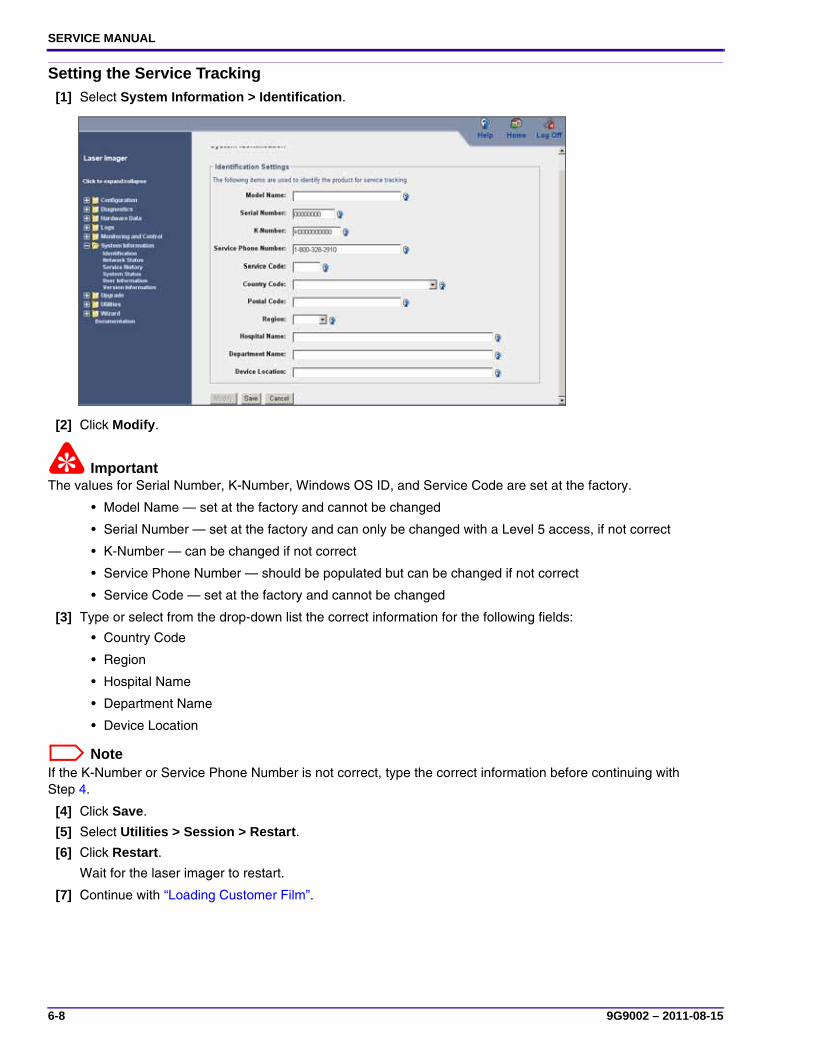
SERVICE MANUAL
6-8 9G9002 – 2011-08-15
Setting the Service Tracking[1] Select System Information > Identification.
[2] Click Modify.
ImportantThe values for Serial Number, K-Number, Windows OS ID, and Service Code are set at the factory.
• Model Name — set at the factory and cannot be changed
• Serial Number — set at the factory and can only be changed with a Level 5 access, if not correct
• K-Number — can be changed if not correct
• Service Phone Number — should be populated but can be changed if not correct
• Service Code — set at the factory and cannot be changed
[3] Type or select from the drop-down list the correct information for the following fields:
• Country Code
• Region
• Hospital Name
• Department Name
• Device Location
NoteIf the K-Number or Service Phone Number is not correct, type the correct information before continuing with Step 4.
[4] Click Save.
[5] Select Utilities > Session > Restart.
[6] Click Restart.
Wait for the laser imager to restart.
[7] Continue with “Loading Customer Film”.
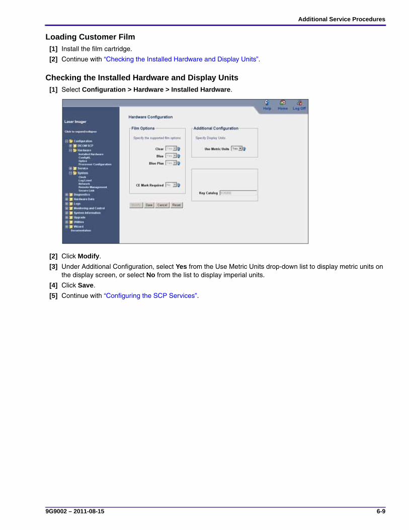
Additional Service Procedures
9G9002 – 2011-08-15 6-9
Loading Customer Film [1] Install the film cartridge.
[2] Continue with “Checking the Installed Hardware and Display Units”.
Checking the Installed Hardware and Display Units[1] Select Configuration > Hardware > Installed Hardware.
[2] Click Modify.
[3] Under Additional Configuration, select Yes from the Use Metric Units drop-down list to display metric units on the display screen, or select No from the list to display imperial units.
[4] Click Save.
[5] Continue with “Configuring the SCP Services”.
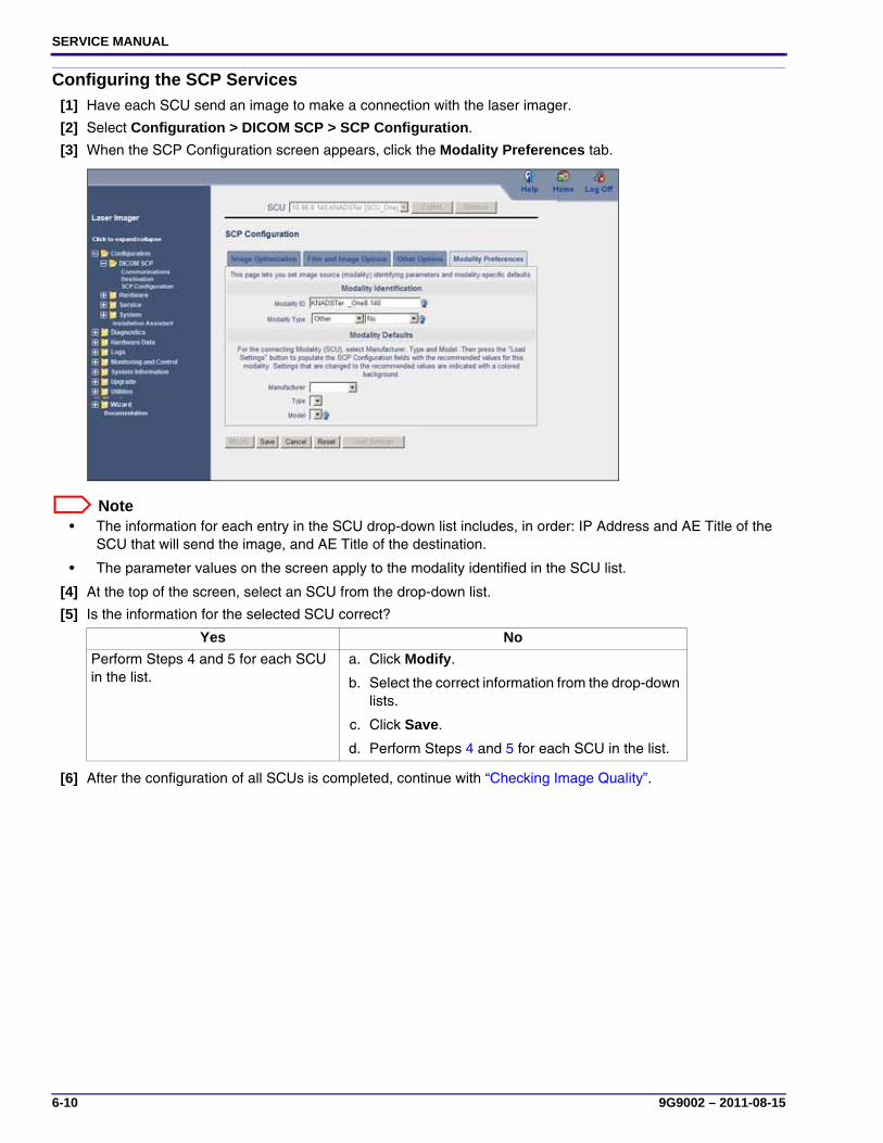
SERVICE MANUAL
6-10 9G9002 – 2011-08-15
Configuring the SCP Services[1] Have each SCU send an image to make a connection with the laser imager.
[2] Select Configuration > DICOM SCP > SCP Configuration.
[3] When the SCP Configuration screen appears, click the Modality Preferences tab.
Note• The information for each entry in the SCU drop-down list includes, in order: IP Address and AE Title of the
SCU that will send the image, and AE Title of the destination.
• The parameter values on the screen apply to the modality identified in the SCU list.
[4] At the top of the screen, select an SCU from the drop-down list.
[5] Is the information for the selected SCU correct?
[6] After the configuration of all SCUs is completed, continue with “Checking Image Quality”.
Yes No
Perform Steps 4 and 5 for each SCU in the list.
a. Click Modify.
b. Select the correct information from the drop-down lists.
c. Click Save.
d. Perform Steps 4 and 5 for each SCU in the list.
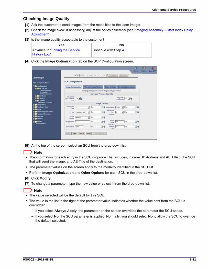
Additional Service Procedures
9G9002 – 2011-08-15 6-11
Checking Image Quality[1] Ask the customer to send images from the modalities to the laser imager.
[2] Check for image skew. If necessary, adjust the optics assembly (see “Imaging Assembly—Start Index Delay Adjustment”).
[3] Is the image quality acceptable to the customer?
[4] Click the Image Optimization tab on the SCP Configuration screen.
[5] At the top of the screen, select an SCU from the drop-down list.
Note• The information for each entry in the SCU drop-down list includes, in order: IP Address and AE Title of the SCU
that will send the image, and AE Title of the destination.
• The parameter values on the screen apply to the modality identified in the SCU list.
• Perform Image Optimization and Other Options for each SCU in the drop-down list.
[6] Click Modify.
[7] To change a parameter, type the new value or select it from the drop-down list.
Note• The value selected will be the default for this SCU.
• The value in the list to the right of the parameter value indicates whether the value sent from the SCU is overridden.
– If you select Always Apply, the parameter on the screen overrides the parameter the SCU sends.
– If you select No, the SCU parameter is applied. Normally, you should select No to allow the SCU to override the default selected.
Yes No
Advance to “Editing the Service History Log”.
Continue with Step 4.

SERVICE MANUAL
6-12 9G9002 – 2011-08-15
[8] Click the Film and Image Options tab.
[9] Select or type the parameter values.
Note• The value selected will be the default for this SCU.
• The value in the list to the right of the parameter value indicates whether the value sent from the SCU is overridden.
– If you select Always Apply, the parameter on the screen overrides the parameter the SCU sends.
– If you select No, the SCU parameter is applied. Normally, you should select No to allow the SCU to override the default selected.
[10] Click the Other Options tab.
[11] Select the parameter values.
[12] After you set the parameters for this SCU, perform the same procedures for each SCU identified in the SCU connection window.
[13] Click Save.
[14] After you complete the configuration of all SCUs, continue with “Editing the Service History Log”.

Additional Service Procedures
9G9002 – 2011-08-15 6-13
Editing the Service History Log[1] Select System Information > Service History.
[2] Click Add.
NoteThe Date Time, Product Service Code, and your User Name and User ID for Secure Tunnel fields are filled in automatically.
[3] Type data about the service performed in the remaining fields.
[4] Click Save.

SERVICE MANUAL
6-14 9G9002 – 2011-08-15
Backing Up and Restoring Configurations
Making a Configuration Backup[1] Log on to the service tool (see “Logging On to the Service Tool”).
[2] Select Utilities > Backup/Restore.
[3] To make a backup of the configuration parameters to the hard drive, click the Backup tab.
[4] To download the backup data to your laptop computer:
(a) Click Download Backup.
(b) Click Save in the File Download window.
(c) Select a destination on your computer to save. If you want to change the name of the saved data file, type a file name.
(d) Click Save to place the backup file in the selected destination.
[5] Log off from the service tool (see “Logging Off the Service Tool”).

Additional Service Procedures
9G9002 – 2011-08-15 6-15
Restoring the Configuration[1] Log on to the service tool (see “Logging On to the Service Tool”).
[2] Select Utilities > Backup/Restore.
[3] Click the Restore tab.
[4] Select the type of information to be restored from the Restore Level drop-down list.
[5] Choose how you want to restore the backup data:
ImportantYou must restart the imager from the service tool.
[6] Select Utilities > Session > Restart.
[7] Click Restart.
Wait for the imager to restart.
[8] If you are finished with the service tool:
(a) Disconnect the laptop computer from the imager.
(b) Install the top cover.
From flash drive Upload stored configuration data from laptop
Click Restore. a. Select the Upload Configuration File check box.
b. Click Select.
c. In the File Upload window, click Browse.
d. When the Choose File window displays, select the .bin file.
e. Click Open, and then click Upload.

SERVICE MANUAL
6-16 9G9002 – 2011-08-15
Upgrading Software and Firmware
Updating a Portable Flash Drive with a New Version of System Software
ImportantEnergize your laptop computer before you insert the flash drive into the USB port.
[1] Energize your laptop computer.
[2] Insert the:
• Portable flash drive into the USB port on your laptop computer.
• Ghost CD into the CD-ROM drive of your laptop computer.
[3] Copy the software from the CD-ROM to the flash drive.
NoteThe new version of system software on the CD-ROM will overwrite the old version on the flash drive.
[4] When the copy is complete, remove the flash drive and CD-ROM from your laptop computer.

Additional Service Procedures
9G9002 – 2011-08-15 6-17
Upgrading the Imager Flash Drive with a New Version of System Software – Ghosting
ImportantSave the backup file to your laptop computer.
[1] Make a backup of the configuration file for the imager (see “Making a Configuration Backup”).
[2] Close the film cartridge.
[3] De-energize the imager.
[4] Remove the back cover (see Adjustments and Replacements, “Back cover”).
[5] Install the portable flash drive that contains the ghost software into one of the USB ports on the DRE board.
NoteThe USB ports are located behind the lower 2 network connections.
[6] Install the back cover, and then attach the power cord.
[7] Energize the imager to begin ghosting.
The imager beeps 3 times when ghosting has completed.
[8] After ghosting has completed, de-energize the imager.
[9] Remove the back cover, and then remove the portable flash drive.
[10] Install the back cover, and then attach the power cord.
[11] Energize the imager.
[12] Do the microcontrollers need to be updated?
[13] Perform “Restoring the Configuration”.
Yes No
a. Perform “Upgrading the Firmware in the Microcontrollers”
b. Continue with Step 13.
Continue with Step 13.
USB Ports (4)

SERVICE MANUAL
6-18 9G9002 – 2011-08-15
Upgrading the Firmware in the Microcontrollers
ImportantYou must perform this procedure when:
• The imager is ghosted and there are changes for the microcontrollers
• Condition code 20-156 is generated
[1] Log on to the service tool (see “Logging On to the Service Tool”).
[2] Select Diagnostics > Scripts.
[3] Select MicroUpdate_WithAutoRestart_ST.vbs from the Script Name drop-down list.
[4] Click Run.
NoteThis procedure updates the microcontrollers as necessary and then restarts the imager. Be patient, as this process could take approximately 10 minutes.

Publication History
A4A9YG220B_111019 I
Publication History
PublicationDate Revision ECO No. Changed Pages File Name Notes
2011/08/15 30 N/A N/A 9G9002-A.pdf New Publication
2011/10/19 - - p. 1-13 A4A9YG220B_111019_Fix.pdf Added a Note to the step [2]. Edited the PDF with Acrobat byKM.

SERVICE MANUAL
II A4A9YG220B_111019
Konica Minolta Medical & Graphic, Inc. 1 Sakura-machi, Hino-shi, Tokyo 191-8511, JAPAN
© Konica Minolta Medical & Graphic, Inc., 2011
KONICA MINOLTA and DRYPRO are trademarks of Konica Minolta Medical & Graphic, Inc.
Pub No. 9G9002
Rev 30
A4A9YG220B_111019_Fix