Service Manual - Eatonpub/@eaton/@hyd/docu… · EATON Duraforce HPR Service Manual E-PUPI-TS019-E...
20
Eaton ® DuraForce™ HPR Service Manual
Transcript of Service Manual - Eatonpub/@eaton/@hyd/docu… · EATON Duraforce HPR Service Manual E-PUPI-TS019-E...
Eaton® DuraForce™ HPR
Service Manual
2 EATON Duraforce HPR Service Manual E-PUPI-TS019-E July 2012
Content Page #
Table of Contents
Load Sense and HP Control Adjustment for HPRTL1 Pump
Set Up 3
Load Sense "Margine Pressure" Adjustment Procedure 4
Horsepower Adjustment by Engine Lug-Down Procedure 5
Load Sense and Horsepower Control Adjustment for HPRTL2 Pump
Set Up 6
Load Sense "Margine Pressure" Adjustment Procedure 7
Horsepower Adjustment by Engine Lug-Down Procedure and Using the Z1 & Z2 Ports 8
Load Sense and Pressure Compensator Control Adjustment for HPR Pump
Set Up 9
Load Sense "Margine Pressure" Adjustment Procedure 10
Pressure Compensator Adjustment Procedure 11
Maximum Displacement Adjustment Procedure for Single HPR Pumps
Set Up & Procedure 12
Minimum Displacement Adjustment Procedure for Single HPR Pumps
Set Up & Procedure 13
Procedure to Measure the Stand-By Pressure on HPR Pumps
Set Up & Procedure 14
E1L Control Adjustment for HPR Pumps
Set Up 15
Load Sense "Margine Pressure" Adjustment Procedure 16
VD3 Performance Valve Adjustment Procedure 17
Environmental Concerns
Protection of the natural fundamentals of life is one of our predominant tasks. We are continuously improving the protection of the environment as far as applications are concerned. We encourage you to contribute your share to comply with this demand. In connection with work to be performed, the environmental regulations of the machine manufacturer must be respected.
In general:
• Greases and oils which cannot be used any more have to be collected. They are normally a threat to water reserves and must be kept away from the environment.
• Adhere to national and local regulations for waste disposal.
Important
You have been provided information on the conversion of DuraForce products. Proper application of the information requires specific training and may require use of specialized tooling and equipment. All requests for training must be coordinated through your Eaton Account Manager. He can also provide you price and availability of any specialized tooling. If you choose to proceed with the conversion of the DuraForce products absent the necessary training and/or these specialized tools, you do so at your risk.
Eaton will accept no claim for warranty resulting from deficiencies in the conversion. Please refer to the Eaton literature web site for warranty information at www.eaton.com/hydraulics/warranty.
3EATON Duraforce HPR Service Manual E-PUPI-TS019-E July 2012
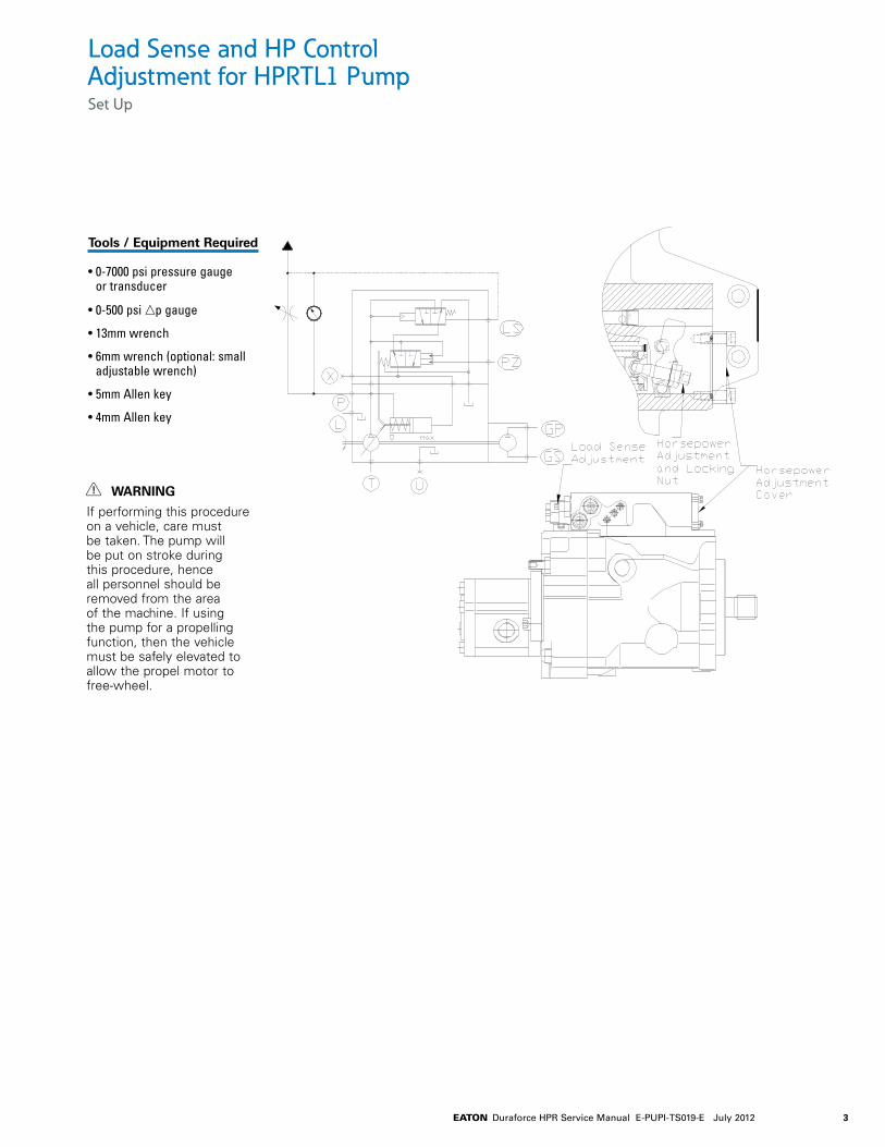
Load Sense and HP Control Adjustment for HPRTL1 PumpSet Up
Tools / Equipment Required
• 0-7000 psi pressure gauge or transducer
• 0-500 psi np gauge
• 13mm wrench
• 6mm wrench (optional: small adjustable wrench)
• 5mm Allen key
• 4mm Allen key
WARNING
If performing this procedure on a vehicle, care must be taken. The pump will be put on stroke during this procedure, hence all personnel should be removed from the area of the machine. If using the pump for a propelling function, then the vehicle must be safely elevated to allow the propel motor to free-wheel.
4 EATON Duraforce HPR Service Manual E-PUPI-TS019-E July 2012
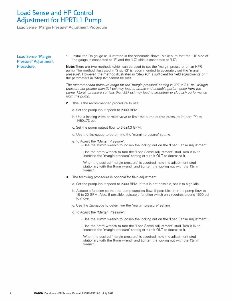
Load Sense and HP Control Adjustment for HPRTL1 PumpLoad Sense "Margin Pressure" Adjustment Procedure
1. Install the Dp-gauge as illustrated in the schematic above. Make sure that the "HI" side of the gauge is connected to "P" and the "LO" side is connected to "LS".
Note: There are two methods which can be used to set the "margin pressure" on an HPR pump. The method illustrated in "Step #2" is recommended to accurately set the "margin pressure". However, the method illustrated in "Step #3" is sufficient for field adjustments or if the parameters in "Step #2" cannot be met.
The recommended pressure range for the "margin pressure" setting is 297 to 311 psi. Margin pressure set greater than 311 psi may lead to erratic and unstable performance from the pump. Margin pressure set less than 297 psi may lead to smoother or sluggish performance from the pump.
2. This is the recommended procedure to use:
a. Set the pump input speed to 2300 RPM.
b. Use a loading valve or relief valve to limit the pump output pressure (at port "P") to 1450±73 psi.
c. Set the pump output flow to 6.6±1.3 GPM.
d. Use the np-gauge to determine the "margin pressure" setting.
e. To Adjust the "Margin Pressure": - Use the 13mm wrench to loosen the locking nut on the "Load Sense Adjustment"
- Use the 6mm wrench to turn the "Load Sense Adjustment" stud. Turn it IN to increase the "margin pressure" setting or turn it OUT to decrease it.
- When the desired "margin pressure" is acquired, hold the adjustment stud stationary with the 6mm wrench and tighten the locking nut with the 13mm wrench.
3. The following procedure is optional for field adjustment:
a. Set the pump input speed to 2300 RPM. If this is not possible, set it to high idle.
b. Actuate a function so that the pump supplies flow. If possible, limit the pump flow to 18 to 20 GPM. Also, if possible, actuate a function which only requires around 1500 psi to move.
c. Use the np-gauge to determine the "margin pressure" setting
d. To Adjust the "Margin Pressure":
- Use the 13mm wrench to loosen the locking nut on the "Load Sense Adjustment".
- Use the 6mm wrench to turn the "Load Sense Adjustment" stud. Turn it IN to increase the "margin pressure" setting or turn it OUT to decrease it.
- When the desired "margin pressure" is acquired, hold the adjustment stud stationary with the 6mm wrench and tighten the locking nut with the 13mm wrench.
Load Sense "Margin Pressure" Adjustment Procedure:
5EATON Duraforce HPR Service Manual E-PUPI-TS019-E July 2012
Load Sense and HP Control Adjustment for HPRTL1 PumpHorsepower Adjustment by Engine Lug-Down Procedure
Note: This is a Field Adustment Procedure, hence it is only intended to help set the horsepower control to prevent the prime mover from stalling.
1. Create the following load condition:
a. Set the prime mover at maximum speed.
b. Actuate enough functions as to demand 30 GPM (or more) flow.
c. Gradually and smoothly increase the load on the pump from zero load to maximum pump output pressure.
DO NOT Stall any cylinder function that have workport relief valves adjusted higher than the main load sense relief valve (if the main load sense relief valve is active, the pump displacement will decrease which will reduce the horsepower demand from the pump)
2. To Adjust the Horsepower control:
a. Stop the function and turn the engine off.
b. Use the 5mm wrench to remove the two bolts that hold the horsepower adjustment cover then remove the cover.
c. While holding the adjustment stud with a 4mm Allen key, use the 13mm wrench to loosen the locking nut on the "horsepower adjustment".
d. Use the 4mm wrench to turn the "horsepower adjustment".
- If the Prime Mover did not stall or lug-down during step one, turn the adjustment stud IN one turn.
- If the Prime Mover stalled during step one, turn the adjustment stud Out one turn
e. While holding the adjustment stud, use the 13mm wrench to thighten the locking nut.
f. Use the 5mm wrench to install the horsepower adjustment cover and tighten the bolts
g. Make sure that the pump’s case is full of oil.
3. Repeat steps #1 and 2 until the Prime Mover lugs down by 100 to 200 RPM, but DOES NOT Stall.
Horsepower Adjustment by Engine Lug-Down:
6 EATON Duraforce HPR Service Manual E-PUPI-TS019-E July 2012
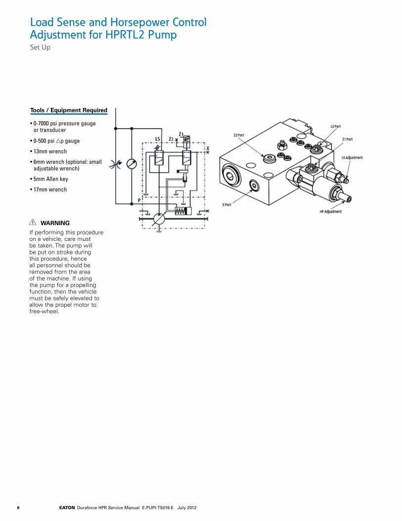
Load Sense and Horsepower Control Adjustment for HPRTL2 PumpSet Up
Tools / Equipment Required
• 0-7000 psi pressure gauge or transducer
• 0-500 psi np gauge
• 13mm wrench
• 6mm wrench (optional: small adjustable wrench)
• 5mm Allen key
• 17mm wrench
WARNING
If performing this procedure on a vehicle, care must be taken. The pump will be put on stroke during this procedure, hence all personnel should be removed from the area of the machine. If using the pump for a propelling function, then the vehicle must be safely elevated to allow the propel motor to free-wheel.
7EATON Duraforce HPR Service Manual E-PUPI-TS019-E July 2012
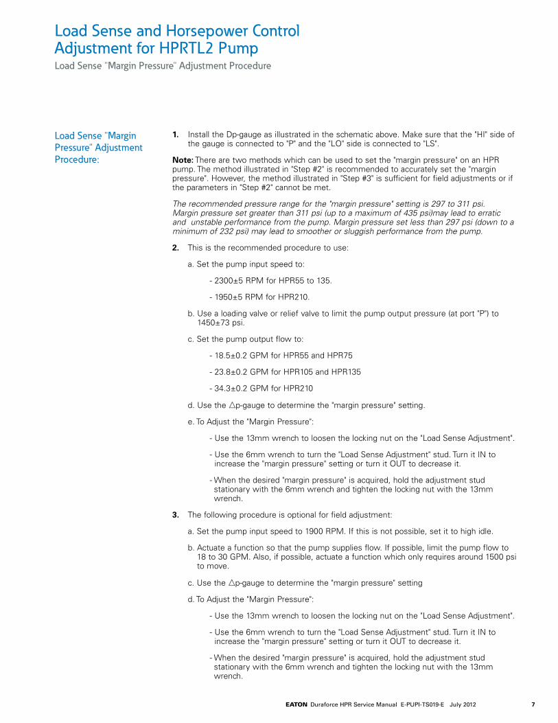
Load Sense and Horsepower Control Adjustment for HPRTL2 PumpLoad Sense "Margin Pressure" Adjustment Procedure
1. Install the Dp-gauge as illustrated in the schematic above. Make sure that the "HI" side of the gauge is connected to "P" and the "LO" side is connected to "LS".
Note: There are two methods which can be used to set the "margin pressure" on an HPR pump. The method illustrated in "Step #2" is recommended to accurately set the "margin pressure". However, the method illustrated in "Step #3" is sufficient for field adjustments or if the parameters in "Step #2" cannot be met.
The recommended pressure range for the "margin pressure" setting is 297 to 311 psi. Margin pressure set greater than 311 psi (up to a maximum of 435 psi)may lead to erratic and unstable performance from the pump. Margin pressure set less than 297 psi (down to a minimum of 232 psi) may lead to smoother or sluggish performance from the pump.
2. This is the recommended procedure to use:
a. Set the pump input speed to:
- 2300±5 RPM for HPR55 to 135.
- 1950±5 RPM for HPR210.
b. Use a loading valve or relief valve to limit the pump output pressure (at port "P") to 1450±73 psi.
c. Set the pump output flow to:
- 18.5±0.2 GPM for HPR55 and HPR75
- 23.8±0.2 GPM for HPR105 and HPR135
- 34.3±0.2 GPM for HPR210
d. Use the np-gauge to determine the "margin pressure" setting.
e. To Adjust the "Margin Pressure":
- Use the 13mm wrench to loosen the locking nut on the "Load Sense Adjustment".
- Use the 6mm wrench to turn the "Load Sense Adjustment" stud. Turn it IN to increase the "margin pressure" setting or turn it OUT to decrease it.
- When the desired "margin pressure" is acquired, hold the adjustment stud stationary with the 6mm wrench and tighten the locking nut with the 13mm wrench.
3. The following procedure is optional for field adjustment:
a. Set the pump input speed to 1900 RPM. If this is not possible, set it to high idle.
b. Actuate a function so that the pump supplies flow. If possible, limit the pump flow to 18 to 30 GPM. Also, if possible, actuate a function which only requires around 1500 psi to move.
c. Use the np-gauge to determine the "margin pressure" setting
d. To Adjust the "Margin Pressure":
- Use the 13mm wrench to loosen the locking nut on the "Load Sense Adjustment".
- Use the 6mm wrench to turn the "Load Sense Adjustment" stud. Turn it IN to increase the "margin pressure" setting or turn it OUT to decrease it.
- When the desired "margin pressure" is acquired, hold the adjustment stud stationary with the 6mm wrench and tighten the locking nut with the 13mm wrench.
Load Sense "Margin Pressure" Adjustment Procedure:
8 EATON Duraforce HPR Service Manual E-PUPI-TS019-E July 2012
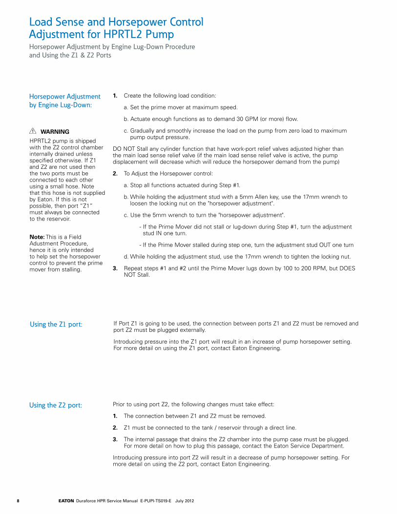
Load Sense and Horsepower Control Adjustment for HPRTL2 PumpHorsepower Adjustment by Engine Lug-Down Procedure and Using the Z1 & Z2 Ports
1. Create the following load condition:
a. Set the prime mover at maximum speed.
b. Actuate enough functions as to demand 30 GPM (or more) flow.
c. Gradually and smoothly increase the load on the pump from zero load to maximum pump output pressure.
DO NOT Stall any cylinder function that have work-port relief valves adjusted higher than the main load sense relief valve (if the main load sense relief valve is active, the pump displacement will decrease which will reduce the horsepower demand from the pump)
2. To Adjust the Horsepower control:
a. Stop all functions actuated during Step #1.
b. While holding the adjustment stud with a 5mm Allen key, use the 17mm wrench to loosen the locking nut on the "horsepower adjustment".
c. Use the 5mm wrench to turn the "horsepower adjustment".
- If the Prime Mover did not stall or lug-down during Step #1, turn the adjustment stud IN one turn.
- If the Prime Mover stalled during step one, turn the adjustment stud OUT one turn
d. While holding the adjustment stud, use the 17mm wrench to tighten the locking nut.
3. Repeat steps #1 and #2 until the Prime Mover lugs down by 100 to 200 RPM, but DOES NOT Stall.
Horsepower Adjustment by Engine Lug-Down:
WARNING
HPRTL2 pump is shipped with the Z2 control chamber internally drained unless specified otherwise. If Z1 and Z2 are not used then the two ports must be connected to each other using a small hose. Note that this hose is not supplied by Eaton. If this is not possible, then port “Z1” must always be connected to the reservoir.
Note: This is a Field Adustment Procedure, hence it is only intended to help set the horsepower control to prevent the prime mover from stalling.
If Port Z1 is going to be used, the connection between ports Z1 and Z2 must be removed and port Z2 must be plugged externally.
Introducing pressure into the Z1 port will result in an increase of pump horsepower setting. For more detail on using the Z1 port, contact Eaton Engineering.
Using the Z1 port:
Prior to using port Z2, the following changes must take effect:
1. The connection between Z1 and Z2 must be removed.
2. Z1 must be connected to the tank / reservoir through a direct line.
3. The internal passage that drains the Z2 chamber into the pump case must be plugged. For more detail on how to plug this passage, contact the Eaton Service Department.
Introducing pressure into port Z2 will result in a decrease of pump horsepower setting. For more detail on using the Z2 port, contact Eaton Engineering.
Using the Z2 port:
9EATON Duraforce HPR Service Manual E-PUPI-TS019-E July 2012
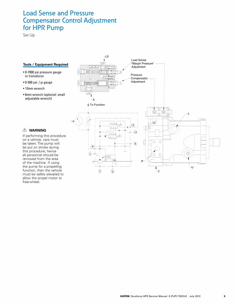
L
UT
P0 max
P
L
T U
LS
LS
X
p
To Function
X
LS
PressureCompensatorAdjustment
Load Sense"Margin Pressure"Adjustment
Load Sense and Pressure Compensator Control Adjustment for HPR PumpSet Up
Tools / Equipment Required
• 0-7000 psi pressure gauge or transducer
• 0-500 psi np gauge
• 13mm wrench
• 6mm wrench (optional: small adjustable wrench)
WARNING
If performing this procedure on a vehicle, care must be taken. The pump will be put on stroke during this procedure; hence all personnel should be removed from the area of the machine. If using the pump for a propelling function, then the vehicle must be safely elevated to allow the propel motor to free-wheel.
10 EATON Duraforce HPR Service Manual E-PUPI-TS019-E July 2012
Load Sense and Pressure Compensator Control Adjustment for HPR PumpLoad Sense "Margin Pressure" Adjustment Procedure
1. Install the np-gauge as illustrated in the schematic above. Make sure that the "HI" side of the gauge is connected to "P" and the "LO" side is connected to "LS".
2. This is the recommended procedure to use:
a. Set the pump input speed to:
HPR55 to 135 HPR210 HPR280 2200±5 RPM 1950±5 RPM 1800±5 RPM
b. Use a loading valve or relief valve to limit the pump output pressure (at port "P") to 1450±73 psi.
c. Set the pump output flow to 18.5±1.3 GPM.
d. Use the Dp-gauge to determine the "margin pressure" setting.
e. To Adjust the "Margin Pressure":
• Use the 13mm wrench to loosen the locking nut on the "Load Sense Adjustment".
• Use the 6mm wrench to turn the "Load Sense Adjustment" stud. Turn it IN to increase the "margin pressure" setting or turn it OUT to decrease it.
• When the desired "margin pressure" is acquired, hold the adjustment stud stationary with the 6mm wrench and tighten the locking nut with the 13mm wrench.
3. The following procedure is optional for field adjustment:
a. Set the pump input speed to high idle.
b. Actuate a function so that the pump supplies flow. If possible, limit the pump flow to 18 to 20 GPM. Also, if possible, actuate a function which only requires around 1500 psi to move.
c. Use the Dp-gauge to determine the "margin pressure" setting.
d. To Adjust the "Margin Pressure":
• Use the 13mm wrench to loosen the locking nut on the "Load Sense Adjustment".
• Use the 6mm wrench to turn the "Load Sense Adjustment" stud. Turn it IN to increase the "margin pressure" setting or turn it OUT to decrease it.
• When the desired "margin pressure" is acquired, hold the adjustment stud stationary with the 6mm wrench and tighten the locking nut with the 13mm wrench.
Load Sense "Margin Pressure" Adjustment Procedure:
Note: There are two methods which can be used to set the "margin pressure" on an HPR pump. The method illustrated in "Step #2" is recommended to accurately set the "margin pressure". However, the method illustrated in "Step #3" is sufficient for field adjustments or if the parameters in "Step #2" cannot be met.
Important
The recommended pressure range for the "margin pressure" setting is 290 to 305 psi. Margin pressure set greater than 305 psi may lead to erratic and unstable performance from the pump. Margin pressure set less than 290 psi may lead to smoother or sluggish performance from the pump.
11EATON Duraforce HPR Service Manual E-PUPI-TS019-E July 2012
Load Sense and Pressure Compensator Control Adjustment for HPR PumpPressure Compensator Adjustment Procedure
1. Install the 0-7000 psi pressure gauge to measure pump outlet pressure (port "P").
2. Block the pump outlet pressure (port "P"). This can be done by:
• Deadheading a cylinder that the HPR supplies flow to
• Pinning the wheel or track motor that the HPR supplies flow to
3. Make sure that all supplemental relief valves in the HPR pump's circuit are adjusted HIGHER than the desired pump pressure compensator setting.
4. Set the prime mover to high idle.
5. Actuate the function from step #2 and read the value on the pressure gauge.
6. To Adjust the Pressure Compensator:
• Use the 13mm wrench to loosen the locking nut on the "Pressure Compensator Adjustment".
• Use the 6mm wrench to turn the "Pressure Compensator Adjustment" stud. Turn it IN to increase the pressure compensation setting or turn it OUT to decrease it.
• When the desired pressure setting is acquired, hold the adjustment stud stationary with the 6mm wrench and tighten the locking nut with the 13mm wrench.
Note: The pressure compensator spring in this control is NOT adjustable for the full pressure range of the pump. There are several pressure compensator springs available and each spring has a limited pressure range. Consult Eaton Engineering for a listing of springs if you cannot adjust the pump control to the desired pressure setting.
Pressure Compensator Adjustment:
12 EATON Duraforce HPR Service Manual E-PUPI-TS019-E July 2012
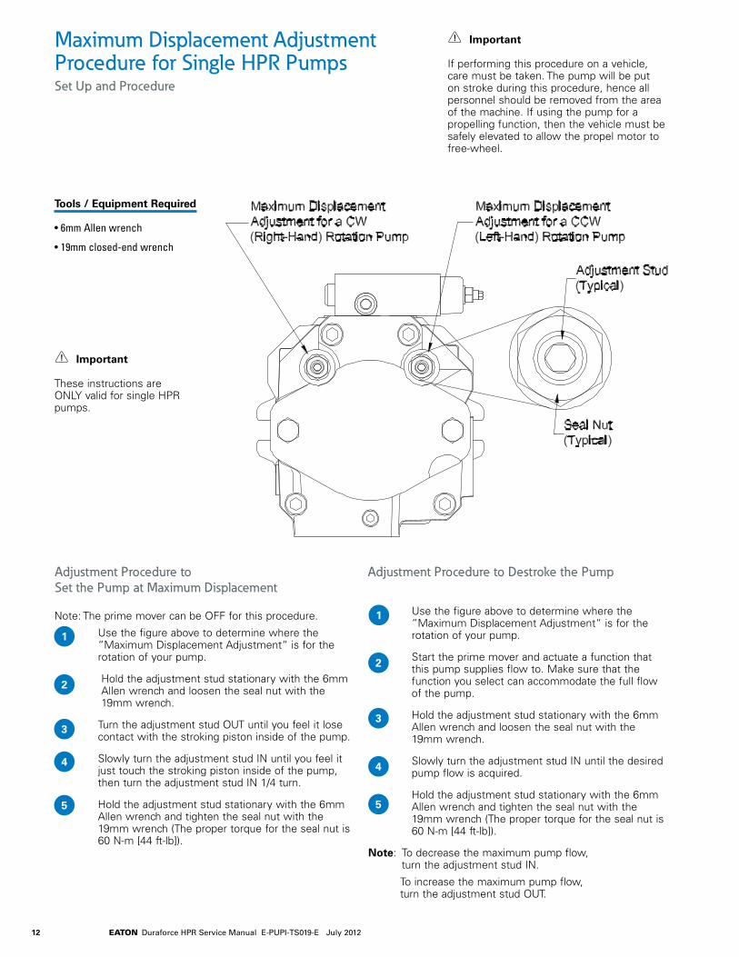
Maximum Displacement Adjustment Procedure for Single HPR PumpsSet Up and Procedure
Note: The prime mover can be OFF for this procedure.
Use the figure above to determine where the “Maximum Displacement Adjustment“ is for the rotation of your pump.
Hold the adjustment stud stationary with the 6mm Allen wrench and loosen the seal nut with the 19mm wrench.
Turn the adjustment stud OUT until you feel it lose contact with the stroking piston inside of the pump.
Slowly turn the adjustment stud IN until you feel it just touch the stroking piston inside of the pump, then turn the adjustment stud IN 1/4 turn.
Hold the adjustment stud stationary with the 6mm Allen wrench and tighten the seal nut with the 19mm wrench (The proper torque for the seal nut is 60 N-m [44 ft-lb]).
1
Use the figure above to determine where the “Maximum Displacement Adjustment“ is for the rotation of your pump.
Start the prime mover and actuate a function that this pump supplies flow to. Make sure that the function you select can accommodate the full flow of the pump.
Hold the adjustment stud stationary with the 6mm Allen wrench and loosen the seal nut with the 19mm wrench.
Slowly turn the adjustment stud IN until the desired pump flow is acquired.
Hold the adjustment stud stationary with the 6mm Allen wrench and tighten the seal nut with the 19mm wrench (The proper torque for the seal nut is 60 N-m [44 ft-lb]).
Note: To decrease the maximum pump flow, turn the adjustment stud IN.
To increase the maximum pump flow, turn the adjustment stud OUT.
1
2
2
33
4 4
5 5
Important
If performing this procedure on a vehicle, care must be taken. The pump will be put on stroke during this procedure, hence all personnel should be removed from the area of the machine. If using the pump for a propelling function, then the vehicle must be safely elevated to allow the propel motor to free-wheel.
Important
These instructions are ONLY valid for single HPR pumps.
Adjustment Procedure to Set the Pump at Maximum Displacement
Adjustment Procedure to Destroke the Pump
Tools / Equipment Required
• 6mm Allen wrench
• 19mm closed-end wrench
13EATON Duraforce HPR Service Manual E-PUPI-TS019-E July 2012
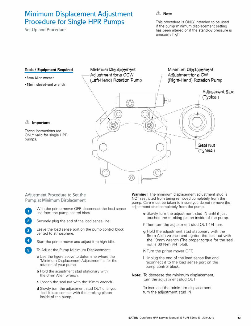
Adjustment Procedure to Set the Pump at Minimum Displacement
With the prime mover OFF, disconnect the load sense line from the pump control block.
Securely plug the end of the load sense line.
Leave the load sense port on the pump control block vented to atmosphere.
Start the prime mover and adjust it to high idle.
To Adjust the Pump Minimum Displacement:
a Use the figure above to determine where the "Minimum Displacement Adjustment" is for the rotation of your pump.
b Hold the adjustment stud stationary with the 6mm Allen wrench.
c Loosen the seal nut with the 19mm wrench.
d Slowly turn the adjustment stud OUT until you feel it lose contact with the stroking piston inside of the pump.
Warning! The minimum displacement adjustment stud is NOT restricted from being removed completely from the pump. Care must be taken to insure you do not remove the adjustment stud completely from the pump.
e Slowly turn the adjustment stud IN until it just touches the stroking piston inside of the pump.
f Then turn the adjustment stud OUT 1/4 turn.
g Hold the adjustment stud stationary with the 6mm Allen wrench and tighten the seal nut with the 19mm wrench (The proper torque for the seal nut is 60 N-m [44 ft-lb]).
h Turn the prime mover OFF.
i Unplug the end of the load sense line and reconnect it to the load sense port on the pump control block.
Note: To decrease the minimum displacement, turn the adjustment stud OUT
To increase the minimum displacement, turn the adjustment stud IN
Minimum Displacement Adjustment Procedure for Single HPR PumpsSet Up and Procedure
1
2
3
4
5
Note
This procedure is ONLY intended to be used if the pump minimum displacement setting has been altered or if the stand-by pressure is unusually high.
Important
These instructions are ONLY valid for single HPR pumps.
Tools / Equipment Required
• 6mm Allen wrench
• 19mm closed-end wrench
14 EATON Duraforce HPR Service Manual E-PUPI-TS019-E July 2012
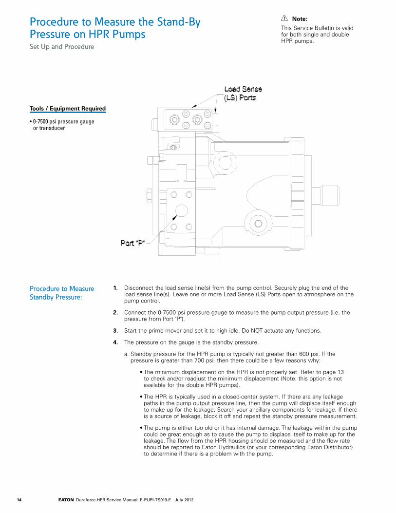
Procedure to Measure the Stand-By Pressure on HPR PumpsSet Up and Procedure
Tools / Equipment Required
• 0-7500 psi pressure gauge or transducer
Note:
This Service Bulletin is valid for both single and double HPR pumps.
1. Disconnect the load sense line(s) from the pump control. Securely plug the end of the load sense line(s). Leave one or more Load Sense (LS) Ports open to atmosphere on the pump control.
2. Connect the 0-7500 psi pressure gauge to measure the pump output pressure (i.e. the pressure from Port "P").
3. Start the prime mover and set it to high idle. Do NOT actuate any functions.
4. The pressure on the gauge is the standby pressure.
a. Standby pressure for the HPR pump is typically not greater than 600 psi. If the pressure is greater than 700 psi, then there could be a few reasons why:
• The minimum displacement on the HPR is not properly set. Refer to page 13 to check and/or readjust the minimum displacement (Note: this option is not available for the double HPR pumps).
• The HPR is typically used in a closed-center system. If there are any leakage paths in the pump output pressure line, then the pump will displace itself enough to make up for the leakage. Search your ancillary components for leakage. If there is a source of leakage, block it off and repeat the standby pressure measurement.
• The pump is either too old or it has internal damage. The leakage within the pump could be great enough as to cause the pump to displace itself to make up for the leakage. The flow from the HPR housing should be measured and the flow rate should be reported to Eaton Hydraulics (or your corresponding Eaton Distributor) to determine if there is a problem with the pump.
Procedure to Measure Standby Pressure:
15EATON Duraforce HPR Service Manual E-PUPI-TS019-E July 2012
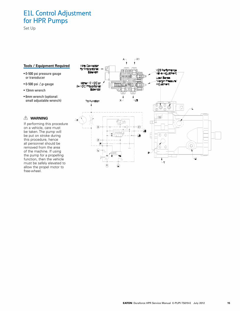
E1L Control Adjustment for HPR PumpsSet Up
Tools / Equipment Required
• 0-500 psi pressure gauge or transducer
• 0-500 psi np-gauge
• 13mm wrench
• 6mm wrench (optional: small adjustable wrench)
WARNING
If performing this procedure on a vehicle, care must be taken. The pump will be put on stroke during this procedure, hence all personnel should be removed from the area of the machine. If using the pump for a propelling function, then the vehicle must be safely elevated to allow the propel motor to free-wheel.
16 EATON Duraforce HPR Service Manual E-PUPI-TS019-E July 2012
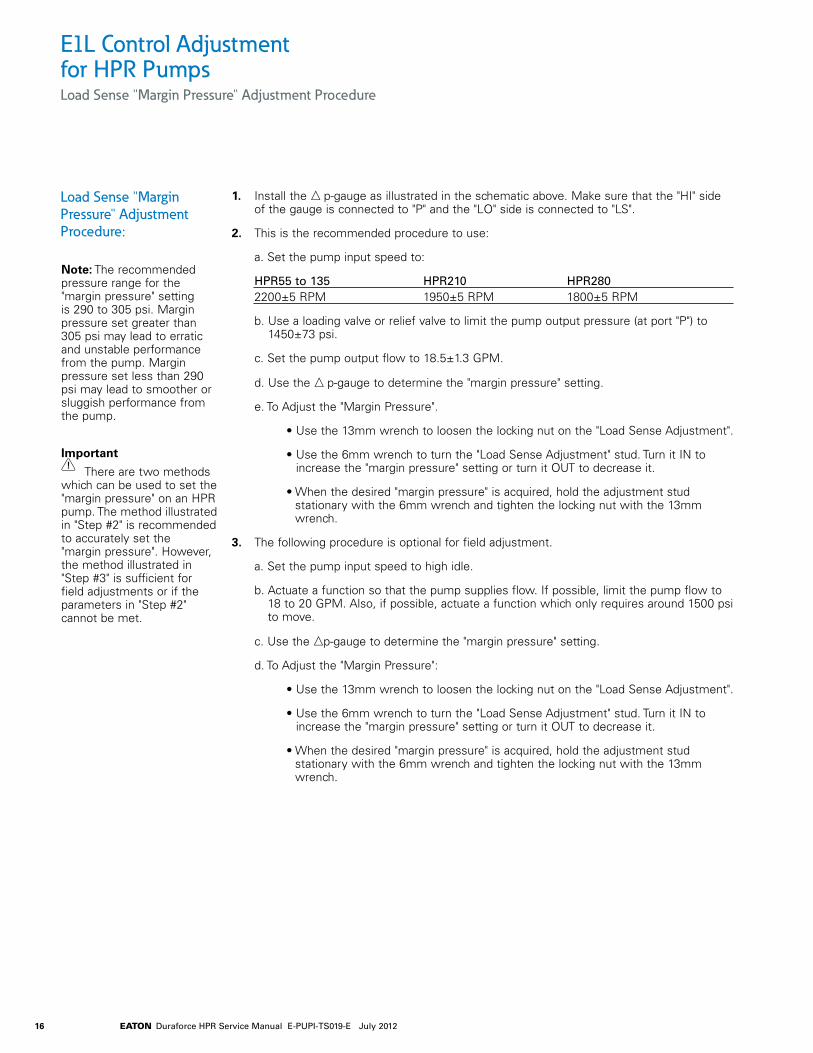
E1L Control Adjustment for HPR PumpsLoad Sense "Margin Pressure" Adjustment Procedure
1. Install the n p-gauge as illustrated in the schematic above. Make sure that the "HI" side of the gauge is connected to "P" and the "LO" side is connected to "LS".
2. This is the recommended procedure to use:
a. Set the pump input speed to:
HPR55 to 135 HPR210 HPR280 2200±5 RPM 1950±5 RPM 1800±5 RPM
b. Use a loading valve or relief valve to limit the pump output pressure (at port "P") to 1450±73 psi.
c. Set the pump output flow to 18.5±1.3 GPM.
d. Use the n p-gauge to determine the "margin pressure" setting.
e. To Adjust the "Margin Pressure".
• Use the 13mm wrench to loosen the locking nut on the "Load Sense Adjustment".
• Use the 6mm wrench to turn the "Load Sense Adjustment" stud. Turn it IN to increase the "margin pressure" setting or turn it OUT to decrease it.
• When the desired "margin pressure" is acquired, hold the adjustment stud stationary with the 6mm wrench and tighten the locking nut with the 13mm wrench.
3. The following procedure is optional for field adjustment.
a. Set the pump input speed to high idle.
b. Actuate a function so that the pump supplies flow. If possible, limit the pump flow to 18 to 20 GPM. Also, if possible, actuate a function which only requires around 1500 psi to move.
c. Use the np-gauge to determine the "margin pressure" setting.
d. To Adjust the "Margin Pressure":
• Use the 13mm wrench to loosen the locking nut on the "Load Sense Adjustment".
• Use the 6mm wrench to turn the "Load Sense Adjustment" stud. Turn it IN to increase the "margin pressure" setting or turn it OUT to decrease it.
• When the desired "margin pressure" is acquired, hold the adjustment stud stationary with the 6mm wrench and tighten the locking nut with the 13mm wrench.
Load Sense "Margin Pressure" Adjustment Procedure:
Note: The recommended pressure range for the "margin pressure" setting is 290 to 305 psi. Margin pressure set greater than 305 psi may lead to erratic and unstable performance from the pump. Margin pressure set less than 290 psi may lead to smoother or sluggish performance from the pump.
Important
There are two methods which can be used to set the "margin pressure" on an HPR pump. The method illustrated in "Step #2" is recommended to accurately set the "margin pressure". However, the method illustrated in "Step #3" is sufficient for field adjustments or if the parameters in "Step #2" cannot be met.
17EATON Duraforce HPR Service Manual E-PUPI-TS019-E July 2012
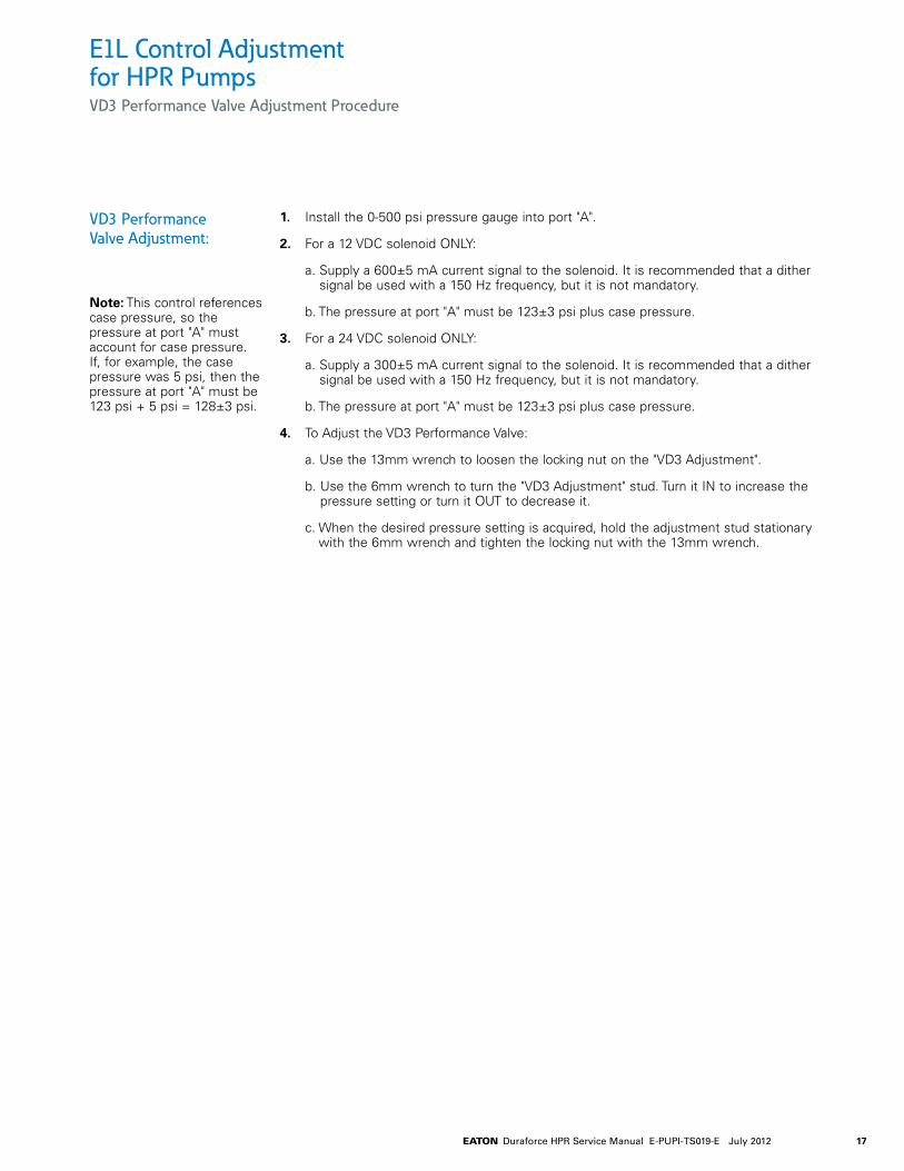
E1L Control Adjustment for HPR PumpsVD3 Performance Valve Adjustment Procedure
1. Install the 0-500 psi pressure gauge into port "A".
2. For a 12 VDC solenoid ONLY:
a. Supply a 600±5 mA current signal to the solenoid. It is recommended that a dither signal be used with a 150 Hz frequency, but it is not mandatory.
b. The pressure at port "A" must be 123±3 psi plus case pressure.
3. For a 24 VDC solenoid ONLY:
a. Supply a 300±5 mA current signal to the solenoid. It is recommended that a dither signal be used with a 150 Hz frequency, but it is not mandatory.
b. The pressure at port "A" must be 123±3 psi plus case pressure.
4. To Adjust the VD3 Performance Valve:
a. Use the 13mm wrench to loosen the locking nut on the "VD3 Adjustment".
b. Use the 6mm wrench to turn the "VD3 Adjustment" stud. Turn it IN to increase the pressure setting or turn it OUT to decrease it.
c. When the desired pressure setting is acquired, hold the adjustment stud stationary with the 6mm wrench and tighten the locking nut with the 13mm wrench.
VD3 Performance Valve Adjustment:
Note: This control references case pressure, so the pressure at port "A" must account for case pressure. If, for example, the case pressure was 5 psi, then the pressure at port "A" must be 123 psi + 5 psi = 128±3 psi.

18 EATON Duraforce HPR Service Manual E-PUPI-TS019-E July 2012

19EATON Duraforce HPR Service Manual E-PUPI-TS019-E July 2012

EatonHydraulics Group USA14615 Lone Oak RoadEden Prairie, MN 55344USATel: 952-937-9800Fax: 952-294-7722www.eaton.com/hydraulics
EatonHydraulics Group EuropeRoute de la Longeraie 71110 MorgesSwitzerlandTel: +41 (0) 21 811 4600Fax: +41 (0) 21 811 4601
Eaton Hydraulics Group Asia PacificEaton BuildingNo.7 Lane 280 Linhong Road Changning District, Shanghai200335 ChinaTel: (+86 21) 5200 0099Fax: (+86 21) 2230 7240
© 2012 Eaton CorporationAll Rights Reserved Printed in USADocument No. E-PUPI-TM019-EJuly 2012