Eaton DuraForce™ HMV Conversion Procedurespub/@eaton/@hyd/documents/content/...EATON Duraforce HMV...
32
Eaton ® DuraForce™ HMV Conversion Procedures
-
Upload
dinhnguyet -
Category
Documents
-
view
224 -
download
3
Transcript of Eaton DuraForce™ HMV Conversion Procedurespub/@eaton/@hyd/documents/content/...EATON Duraforce HMV...

Eaton® DuraForce™ HMV Conversion Procedures
2 EATON Duraforce HMV Conversion Procedures Manual E-MOPI-TM006-E July 2012
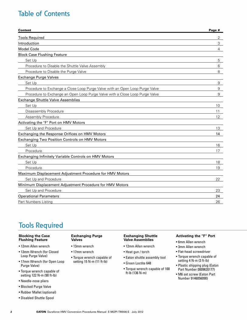
Content Page #
Table of Contents
Tools Required 2
Introduction 3
Model Code 4
Block Case Flushing Feature
Set Up 5
Procedure to Disable the Shuttle Valve Assembly 6
Procedure to Disable the Purge Valve 8
Exchange Purge Valves
Set Up 9
Procedure to Exchange a Close Loop Purge Valve with an Open Loop Purge Valve 9
Procedure to Exchange an Open Loop Purge Valve with a Close Loop Purge Valve 9
Exchange Shuttle Valve Assemblies
Set Up 10
Disassembly Procedure 11
Assembly Procedure 12
Activating the "F" Port on HMV Motors
Set Up and Procedure 13
Exchanging the Response Orifices on HMV Motors 14
Exchanging Two Position Controls on HMV Motors
Set Up 16
Procedure 17
Exchanging Infinitely Variable Controls on HMV Motors
Set Up 18
Procedure 19
Maximum Displacement Adjustment Procedure for HMV Motors
Set Up and Procedure 22
Minimum Displacement Adjustment Procedure for HMV Motors
Set Up and Procedure 23
Operational Parameters 24
Part Numbers Listing 26
Blocking the Case Flushing Feature
• 12mm Allen wrench
• 13mm Wrench (for Closed Loop Purge Valve)
• 17mm Wrench (for Open Loop Purge Valve)
• Torque wrench capable of setting 122 N-m (90 ft-lb)
• Needle-nose pliers
• Blocked Purge Valve
• Rubber Mallet (optional)
• Disabled Shuttle Spool
Exchanging Purge Valves
• 13mm wrench
• 17mm wrench
• Torque wrench capable of setting 15 N-m (11 ft-lb)
Exchanging Shuttle Valve Assemblies
• 12mm Allen wrench
• Heat gun / torch
• Eaton shuttle assembly tool
• Green Loctite 648
• Torque wrench capable of 100 ft-lb (136 N-m)
Activating the "F" Port
• 6mm Allen wrench• 3mm Allen wrench• Flat-head screwdriver• Torque wrench capable of
setting 4 N-m (3 ft-lb)• Plastic shipping plug (Eaton
Part Number 0009620177)• M6 set screw (Eaton Part
Number 9146056090)
Tools Required

3EATON Duraforce HMV Conversion Procedures Manual E-MOPI-TM006-E July 2012
This manual will provide you with information and procedures for general conversions of Eaton® DuraForce™ HMV Variable Displacement Open and Closed Loop Hydraulic Motors. Procedures outlined in this manual will allow you to be more flexible with your inventory and better service your customers. To ensure accuracy of conversion and prevent part loss or damage, certain components or subassemblies are disassembled, inspected, and reassembled when removed from the motor.
Training
You have been provided information on the conversion of DuraForce products. Proper application of the information requires specific training and may require use of specialized tooling and equipment. All requests for training must be coordinated through your Eaton Account Manager. He can also provide you price and availability of any specialized tooling. If you choose to proceed with the conversion of the DuraForce products absent the necessary training and/or these specialized tools, you do so at your risk.
Eaton will accept no claim for warranty resulting from deficiencies in the conversion. Please refer to the Eaton literature web site for warranty information at www.eaton.com/hydraulics/warranty.
Labeling Converted Units
All units that have been converted must retain the original Eaton label and have a second Eaton label placed on the unit. This second label at a minimum must state
Converted Eaton Model Code # (Final Eaton model code of the converted unit)
Conversion done by (Name of your company)
Conversion Parts
All requests for specific conversion part information should be addressed to your Eaton account representative. Additional information can be found through your Eaton customer connect portal. All requests or inquiries must be accompanied by the complete model and serial number of the base unit you want to convert.
Cleanliness
Cleanliness is extremely important when repairing a hydrostatic pump or motor. Before disconnecting the lines, clean foreign material from exterior of unit. Work in a clean area. Clean all metal parts in clean solvent. Blow parts dry with air. Don’t wipe parts with cloth or paper towel, because lint or other matter could cause damage. Check all mating surfaces. Replace any parts that have scratches or burrs that could cause leakage. Don’t use coarse grit paper, files or grinders on parts.
Environmental Concerns
Protection of the natural fundamentals of life is one of our predominant tasks. We are continuously improving the protection of the environment as far as applications are concerned. We encourage you to contribute your share to comply with this demand. In connection with work to be performed, the environmental regulations of the machine manufacturer must be respected.
In general:
• Greases and oils which cannot be used any more have to be collected. They are normally a threat to water reserves and must be kept away from the environment.
• Adhere to national and local regulations for waste disposal.
Seals
A good conversion policy is to replace all old seals with new seals whenever units are disassembled. This avoids potential damage during seal removal. Lubricate seals with petroleum jelly. Use only clean and recommended oil when assembling unit. Information on recommended filters and fluids can be found in the Operational Parameters section.
Torque
All torque specifications are for lubricated threads. Bolts for gasketed surfaces should be checked for proper torque.
Introduction
Exchanging the Response Orifices
• 3mm Allen wrench• 4 mm Allen wrench• T25 Torque style wrench• Torque wrench capable of 32
N-m (24 ft-lb)• Petroleum Jelly or clean
grease
Exchanging Two Position Controls
• 3mm Allen wrench• Torque wrench capable of
setting 3.8 N-m (2.8 ft-lb)• New two position motor
control
Exchanging Infinitely Variable Controls
• 3mm Allen wrench.
• Torque wrench capable of setting 4.6 N-m (3.4 ft-lb)
• New motor control
• Small magnet.
• Small needle-nose pliers.
• Long, thin screw driver.
• Petroleum jelly or grease.
Maximum & Minimum Displacement Adjustments
• 6mm Allen wrench
• 19mm closed-end wrench
Tools Required (continued)

4 EATON Duraforce HMV Conversion Procedures Manual E-MOPI-TM006-E July 2012
55 75 105 135 165 210 280 55 75 105 135 165 210 280
Model CodeHMV Variable Displacement Motors (Open & Closed Loop Operation)
The following 31 digit coding system has been developed to identify preferred feature options for the Eaton Closed or Open Loop Hydraulic Motor. Use this code to specify a motor with the desired features. All 31-digits of the code must be present to release a new product number for ordering. Please contact your local customer service representative for leadtime questions.
1 2 3 ProductHMV– Adjustable Fixed Displacement
Motorsl l l l l l l
4 5 6 Displacement055 – 055 cc l075 – 075 cc l105 – 105 cc l135 – 135 cc l165 – 165 cc l210 – 210 cc l280 – 280 cc l
7 Mounting FlangeA – SAE J744 standard l l l l l l lP – Plug-in (*d) l l l8 Output Shaft
C – Splined ANSI B92.1 12/24 - 14 teeth (SAE J744 C)
l l l
D – Splined ANSI B92.1 8/16 - 13 teeth (SAE J744 D&E)
l l
F – Splined ANSI B92.1 8/16 - 15 teeth (SAE J744 F)
l l
K – Splined ANSI B92.1 16/32 - 21 teeth
l l
L – Splined ANSI B92.1 16/32 - 23 teeth
l
M – Splined ANSI B92.1 16/32 - 27 teeth
l l l
N – Splined ANSI B92.1 16/32 - 33 teeth
l
P – Shaft coupling flange size 4 • •9 Porting
M – ISO 6149 metric • • • l l lD – DIN 3852 l l l l10 Auxiliary Mount and Port Locations
1 – radial ports / without PTO l l l l l l l2 – axial ports / without PTO • • •4 – radial ports / splined PTO shaft ANSI
B92.1 16/32 - 21 teeth•
5 – radial ports / splined PTO shaft ANSI B92.1 16/32 - 22 teeth
•
6 – radial ports / splined PTO shaft ANSI B92.1 16/32 - 24 teeth
•
7 – radial ports / splined PTO shaft ANSI B92.1 16/32 - 27 teeth
•
8 – radial ports / PTO shaft coupling flange size 4
• •
9 – radial ports / PTO speed sensor 35 impulses
• • • • • • •
A – radial ports / tandem unit: attachment of a HMV210 (H1)/ (*s)
• •
B – radial ports / tandem unit: attachment of a HMV280 (H1)/ (*s)
•
11 Attachments to Service Ports0 – without l l l l l l l1 – crossover relief block 250 bar (*p) l l l2 – crossover relief block 300 bar (*p) l l l3 – crossover relief block 380 bar (*p) l l l4 – crossover relief block 420 bar (*p) l l l12 Motor ControlA – H1: hydraulic proportional / standard
mountingl l l l l l l
B – E1: electro-proportional/ standard mounting (*y)
l l l l l l l
C – E2: electric two position/ standard mounting (*y)
• • • • • • •
D – E4: electro-proportional/ Vmin = 0 / standard mounting (*y)
• • • • • • •
E – E6: electro-proportional/ Vmin = 0 / standard mounting (*y)
• • • • •
F – E1F: electro-proportional/ side-mounted (*y)
•
H – E4F: electro-proportional/ Vmin = 0 / side-mounted (*y)
•
J – E6F electro-proportional/ Vmin = 0 / side-mounted (*y)
•
K – EH1P: hydraulic proportional/ PCO (*y)
• • • •
L – H1-CA: hydraulic proportional/ CA operation (*m)
• •
M – EH1P-CA: hydraulic proportional/ PCO / CA operation (*z)
• • • •
13 Control Threshold Pressure0 – not applicable (E1; E2; E4; E6(F)) l l l l l l l1 – 7,0 bar (H1; EH1P; EH1P-CA) l l l l l l l2 – 7,5 bar (H1; EH1P; H1-CA) l l l l l l l3 – 8,0 bar (H1; EH1P) l l l l l l l14 Control Solenoids0 – not applicable (H1; H1-CA; H2) l l l l l l lA – AMP / 12V l l l l l l lB – AMP / 24 V l l l l l l lC – DIN / 12 V • • • • • • •D – DIN / 24 V • • • • • • •E – Deutsch / 12V (E1(F); E2; E4(F); E6(F);
EH1P-CA)• • • • • • •
F – Deutsch / 24V (E1(F); E2; E4(F); E6(F); EH1P-CA)
• • • • • • •
15 Response OrificesA – 0,6 mm • • • • • • •E – 1,0 mm l l l l l l l
16 Purge Relief Valve0 – without purge devices l lA – 10 bar standard purge flow l l l l l l lB – 14 bar standard purge flow l l l l l l lC – 10 bar reduced purge flow • • • • • • •D – 14 bar reduced purge flow • • • • • • •E – 10 bar increased purge flow • • • • • • •F – flow controlled 6 l/min (*o) l l l l l l lG – blank plug instead of relief valve (*v) • • • • • • •17 Purge Shuttle Valve0 – Without purge devices l l1 – Standard shuttle valve l l l l l l l2 – Damped shuttle valve • • • • • • •3 – Shuttle valve blocked • • • • • • •18 19 20 Minimum Displacement Setting000 - value
Catalog Pump Rating l l l l l l lNumeric three digit, setting range see positions 4,5,6
• • • • • • •
21 22 23 Maximum Displacement Setting000 - Catalog Pump Rating l l l l l l l24 25 26 Pressure Override Setting000 - value
not applicable l l l l l l l150 -260 bar (numeric 3 digits / EH1P; EH1P-CA only)
• • • • •
27 28 Special Requirements00 – Without (default) l l l l l l l29 Surface Coating0 – anti-rust conservation oil (default) l l l l l l lA – primer blue l l l l l l l30 Unit IdentificationA – Eaton l l l l l l l31 Type Code ReleaseA – Revision Level l l l l l l l
HMV 210 A F M 1 0 A 1 0 A A 1 000 000 000 00 A A A
1 2 3 4 5 6 9 17118 10 18 19 20 2421 2522 26237 1312 1514 16 27 28 313028
(*d) DIN porting only (see position 9)(*e) Availability depends on controller type
(see position 12)(*m) ISO metric porting only (see position 9)(*o) Open loop operation only(*p) Radial service ports only (see position 10)
(*s) Second motor unit has to be specified separately(*v) With blocked purge shuttle valve only
(see position 17)(*y) Solenoids with square cross section(*z) Solenoids with circular cross section

5EATON Duraforce HMV Conversion Procedures Manual E-MOPI-TM006-E July 2012
Blocking the Case Flushing FeatureSet Up
Important
This procedure must be performed in a clean environment using clean Parts, Tools and Lubricants
6 EATON Duraforce HMV Conversion Procedures Manual E-MOPI-TM006-E July 2012
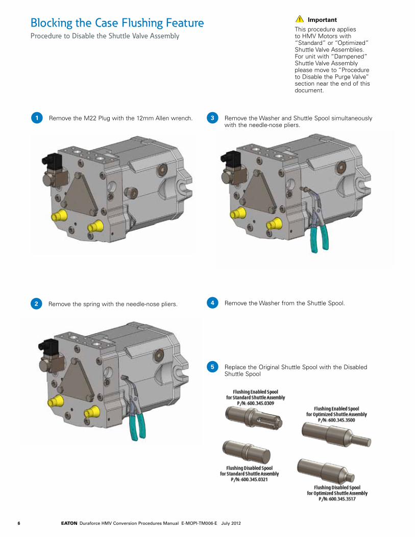
Blocking the Case Flushing FeatureProcedure to Disable the Shuttle Valve Assembly
Remove the M22 Plug with the 12mm Allen wrench.
Important
This procedure applies to HMV Motors with “Standard” or “Optimized” Shuttle Valve Assemblies. For unit with “Dampened” Shuttle Valve Assembly please move to “Procedure to Disable the Purge Valve” section near the end of this document.
1
Remove the spring with the needle-nose pliers.2
Remove the Washer and Shuttle Spool simultaneously with the needle-nose pliers.
3
Remove the Washer from the Shuttle Spool.4
Replace the Original Shuttle Spool with the Disabled Shuttle Spool
5
7EATON Duraforce HMV Conversion Procedures Manual E-MOPI-TM006-E July 2012
Blocking the Case Flushing FeatureProcedure to Disable the Shuttle Valve Assembly
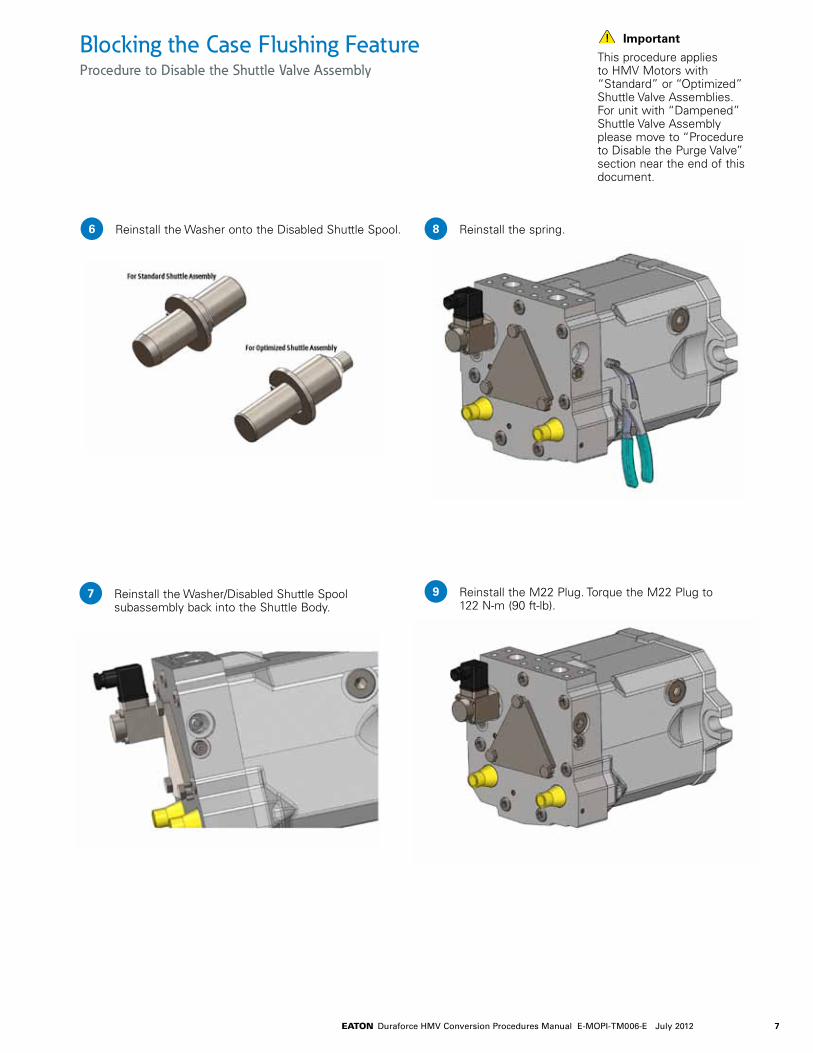
Important
This procedure applies to HMV Motors with “Standard” or “Optimized” Shuttle Valve Assemblies. For unit with “Dampened” Shuttle Valve Assembly please move to “Procedure to Disable the Purge Valve” section near the end of this document.
Reinstall the Washer onto the Disabled Shuttle Spool.6
Reinstall the Washer/Disabled Shuttle Spool subassembly back into the Shuttle Body.
7
Reinstall the spring.8
Reinstall the M22 Plug. Torque the M22 Plug to 122 N-m (90 ft-lb).
9
8 EATON Duraforce HMV Conversion Procedures Manual E-MOPI-TM006-E July 2012
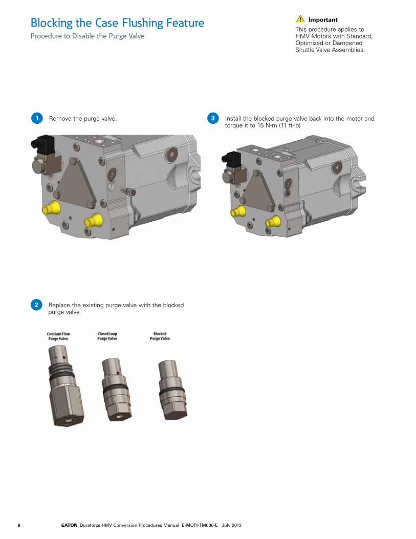
Blocking the Case Flushing FeatureProcedure to Disable the Purge Valve
Remove the purge valve.
Important
This procedure applies to HMV Motors with Standard, Optimized or Dampened Shuttle Valve Assemblies.
1
Replace the existing purge valve with the blocked purge valve
2
Install the blocked purge valve back into the motor and torque it to 15 N-m (11 ft-lb)
3
9EATON Duraforce HMV Conversion Procedures Manual E-MOPI-TM006-E July 2012
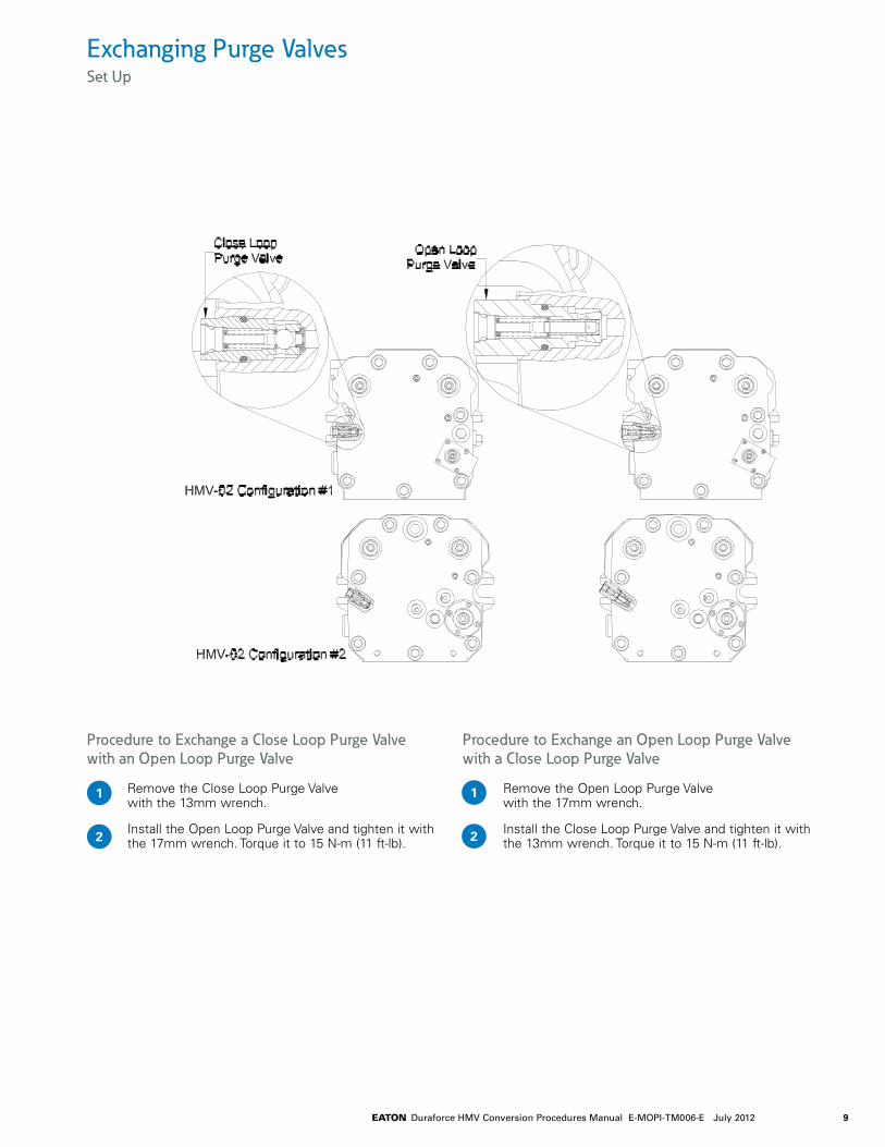
Exchanging Purge Valves Set Up
Procedure to Exchange a Close Loop Purge Valve with an Open Loop Purge Valve
Remove the Close Loop Purge Valve with the 13mm wrench.
Install the Open Loop Purge Valve and tighten it with the 17mm wrench. Torque it to 15 N-m (11 ft-lb).
Procedure to Exchange an Open Loop Purge Valve with a Close Loop Purge Valve
Remove the Open Loop Purge Valve with the 17mm wrench.
Install the Close Loop Purge Valve and tighten it with the 13mm wrench. Torque it to 15 N-m (11 ft-lb).
1
2
1
2

10 EATON Duraforce HMV Conversion Procedures Manual E-MOPI-TM006-E July 2012
Exchanging Shuttle Valve AssembliesSet Up
Important
Although these locations may differ from one unit type to the other, the internal parts are the same.
This procedure must be performed in a clean environment using clean Parts, Tools and Lubricants.
Important
The following image illustrates the different types of shuttle valve assemblies used on Eaton Hydraulics H** motors:
HMF75 HMR75 HMV75
11EATON Duraforce HMV Conversion Procedures Manual E-MOPI-TM006-E July 2012
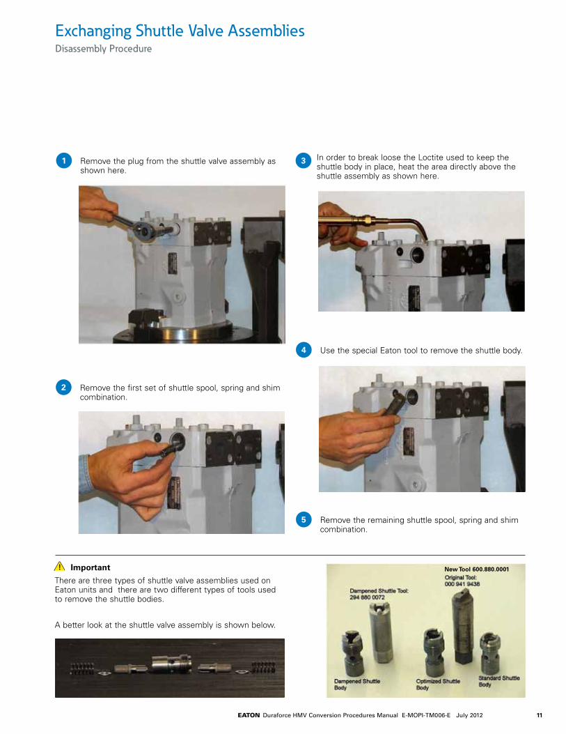
Exchanging Shuttle Valve AssembliesDisassembly Procedure
Remove the plug from the shuttle valve assembly as shown here.
1 In order to break loose the Loctite used to keep the shuttle body in place, heat the area directly above the shuttle assembly as shown here.
3
Remove the first set of shuttle spool, spring and shim combination.
2
Use the special Eaton tool to remove the shuttle body.4
Remove the remaining shuttle spool, spring and shim combination.
5
Important
There are three types of shuttle valve assemblies used on Eaton units and there are two different types of tools used to remove the shuttle bodies.
A better look at the shuttle valve assembly is shown below.
New Tool 600.880.0001

12 EATON Duraforce HMV Conversion Procedures Manual E-MOPI-TM006-E July 2012
Exchanging Shuttle Valve AssembliesAssembly Procedure
Apply Green Loctite 648 on the threads inside the rear head where the shuttle body will be installed.
Assemble the first set of shuttle spool/shim/spring into the shuttle body as shown during the training.
Insert the whole set into the shuttle cavity on the rear head and torque it using the special Eaton tool (refer to the torque chart at the bottom of this page)
1 Install the plug and torque it (refer to the torque chart at the bottom of this page).
5
2
3
Insert the second set of shuttle spool/shim/spring into the shuttle body.
4
Item Description Torque Value ft-lb (N-m)
Standard shuttle body 100+7 (136+9)Dampened shuttle body 44+7 (60+9)Optimized shuttle body 44+7 (60+9)Shuttle cavity plug 90+7 (122+9)
Torque Chart

13EATON Duraforce HMV Conversion Procedures Manual E-MOPI-TM006-E July 2012
Activating the “F” PortSet Up and Procedure
Procedure to Activate the “F” port
Note
The "standard" HMV motors are configured with the "F" Port de-activated. However, if your HMV already has the "F" Port activated, you can still use this document as a check to insure everything is properly set.
Remove the metal plug from Port "F" with the 6mm Allen wrench and discard it.
Referring to "Detail #1", install the M6 set screw (P/N 9146056090) with the 3mm Allen wrench into the designated passage in Port "F". Torque the set screw to 4 N-m (3 ft-lb).
Procedure to Activate the “F” port (continued)
Note
Do NOT use any Loctite on the threads of the M6 set screw (P/N 9146056090).
Install the plastic shipping plug (P/N 0009620177) with the flat-head screwdriver into Port "F".
1
2
3
Detail #1
14 EATON Duraforce HMV Conversion Procedures Manual E-MOPI-TM006-E July 2012
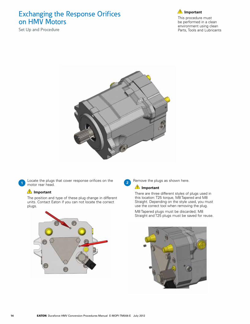
Exchanging the Response Orifices on HMV MotorsSet Up and Procedure
Locate the plugs that cover response orifices on the motor rear head.
Important
This procedure must be performed in a clean environment using clean Parts, Tools and Lubricants
1Remove the plugs as shown here.2
Important
There are three different styles of plugs used in this location: T25 torque, M8 Tapered and M8 Straight. Depending on the style used, you must use the correct tool when removing the plug.
M8 Tapered plugs must be discarded; M8 Straight and T25 plugs must be saved for reuse.
Important
The position and type of these plug change in different units. Contact Eaton if you can not locate the correct plugs.
15EATON Duraforce HMV Conversion Procedures Manual E-MOPI-TM006-E July 2012
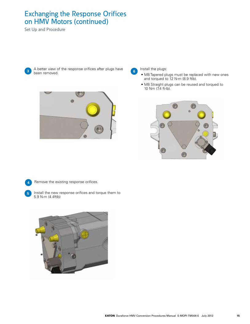
Remove the existing response orifices.4
A better view of the response orifices after plugs have been removed.3 Install the plugs:
• M8 Tapered plugs must be replaced with new ones and torqued to 12 N-m (8.9 ftlb).
• M8 Straight plugs can be reused and torqued to 10 Nm (7.4 ft-lb).
6
Install the new response orifices and torque them to 5.9 N-m (4.4ftlb)
5
Exchanging the Response Orifices on HMV Motors (continued)Set Up and Procedure
16 EATON Duraforce HMV Conversion Procedures Manual E-MOPI-TM006-E July 2012
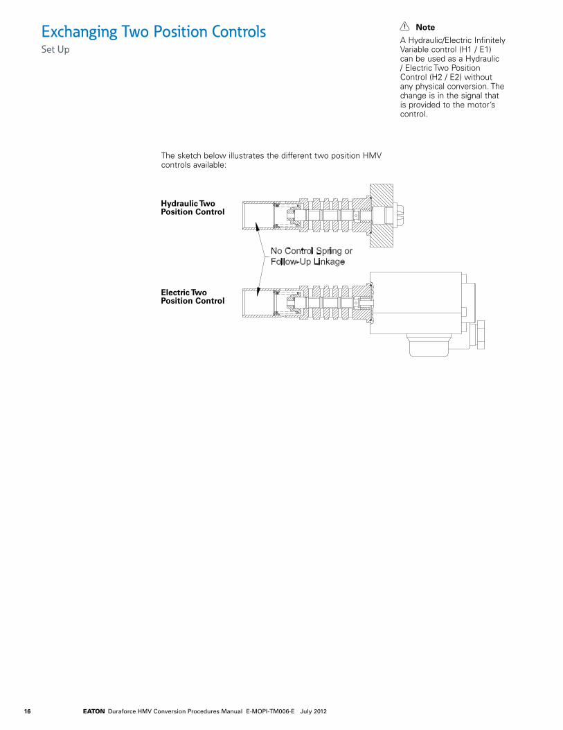
Exchanging Two Position ControlsSet Up
Note
A Hydraulic/Electric Infinitely Variable control (H1 / E1) can be used as a Hydraulic / Electric Two Position Control (H2 / E2) without any physical conversion. The change is in the signal that is provided to the motor’s control.
The sketch below illustrates the different two position HMV controls available:
Hydraulic Two Position Control
Electric Two Position Control

17EATON Duraforce HMV Conversion Procedures Manual E-MOPI-TM006-E July 2012
Exchanging Two Position ControlsProcedure
As illustrated, the Outer Control must be removed from the HMV motor. To do so, remove the four(4) Control Mounting Bolts with the 3mm Allen wrench.
Note
The following procedure includes instructions to convert an HMV motor with an electric two position control to an HMV motor with a hydraulic two position control. This procedure is valid when converting a hydraulic two position control into an electric two position control.
1As illustrated below, install the new HMV two position motor control onto the HMV motor. Make sure that the O-Ring is undamaged and is properly positioned in the o-ring groove prior to installing the new control.
3
As illustrated, remove the ON/OFF solenoid, four (4) control mounting bolts, and the o-ring from the HMV motor.
2 Fasten the new control to the motor with four(4) new control mounting bolts. Torque each mounting bolt to 3.8 N-m (2.8 ft-lb).
4

18 EATON Duraforce HMV Conversion Procedures Manual E-MOPI-TM006-E July 2012
Hydraulic InfinitelyVariable Control
ElectricInfinitelyVariable Control
Hydraulic TwoPosition Control
Electric Two Position Control
Washer Control Spring
Follow-UpLinkage
Follow-Up Linkage
Follow-Up LinkageControl Spring
Control Spring
No Control Spring orFollow-Up Linkage
Exchanging Infinitely Variable ControlsSet Up
Note
This procedure must be performed in a clean environment using clean Parts, Tools and Lubricants.
The sketch below illustrates an HMV motor and some key items which will be referenced throughout this document.
Note
If converting from a Hydraulic/Electric Two Position Control to an Electric/Hydraulic Two Position Control, then refer to pages 14-15 of this document.
A Hydraulic/Electric Infinitely Variable control (H1 / E1) can be used as an Electric/Hydraulic Two Position Control (H2 / E2) without any physical conversion. The change is in the signal that is provided to the motor’s control.
Hydraulic InfinitelyVariable Control
ElectricInfinitelyVariable Control
Hydraulic TwoPosition Control
Electric Two Position Control
Washer Control Spring
Follow-UpLinkage
Follow-Up Linkage
Follow-Up LinkageControl Spring
Control Spring
No Control Spring orFollow-Up Linkage
19EATON Duraforce HMV Conversion Procedures Manual E-MOPI-TM006-E July 2012
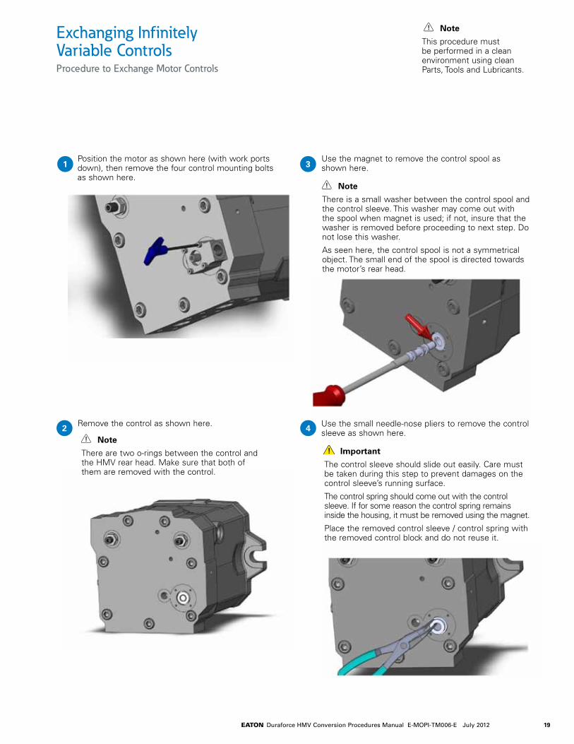
Use the small needle-nose pliers to remove the control sleeve as shown here.
Important
The control sleeve should slide out easily. Care must be taken during this step to prevent damages on the control sleeve’s running surface.
The control spring should come out with the control sleeve. If for some reason the control spring remains inside the housing, it must be removed using the magnet.
Place the removed control sleeve / control spring with the removed control block and do not reuse it.
Exchanging Infinitely Variable ControlsProcedure to Exchange Motor Controls
Position the motor as shown here (with work ports down), then remove the four control mounting bolts as shown here.
Note
This procedure must be performed in a clean environment using clean Parts, Tools and Lubricants.
1Use the magnet to remove the control spool as shown here.3
Remove the control as shown here.2 4Note
There are two o-rings between the control and the HMV rear head. Make sure that both of them are removed with the control.
Note
There is a small washer between the control spool and the control sleeve. This washer may come out with the spool when magnet is used; if not, insure that the washer is removed before proceeding to next step. Do not lose this washer.
As seen here, the control spool is not a symmetrical object. The small end of the spool is directed towards the motor’s rear head.

20 EATON Duraforce HMV Conversion Procedures Manual E-MOPI-TM006-E July 2012
Exchanging Infinitely Variable ControlsProcedure to Exchange Motor Controls
A better view of the control sleeve and control spring after it has been removed.
Note
This procedure must be performed in a clean environment using clean Parts, Tools and Lubricants.
5Use a long screw driver to make sure that follow-up linkage is centered inside the control cavity.7
After the control sleeve / control spring has been removed, the follow-up linkage will be exposed as shown here.
6 Install the new control sleeve / control spring into the control cavity on the motor rear head. The control sleeve should slide into position very easily.
In case of any resistance, remove the control sleeve and reposition the control spring and follow-up linkage.
8
Important
This is a very important step since you will not be able to install the new control sleeve / control spring if the follow-up linkage is not positioned correctly.
Important
Use Petroleum jelly to hold the control spring inside control sleeve as shown here.
Make sure that the o-ring is installed on the control sleeve.

21EATON Duraforce HMV Conversion Procedures Manual E-MOPI-TM006-E July 2012
Install the new control block using the provided M4 bolts and torque them to 4.6 N-m (3.4 ftlb)
Important
At the end of this procedure, the Regulation begin on the HMV motor must be set using the HMV service manual.
Exchanging Infinitely Variable ControlsProcedure to Exchange Motor Controls
Use petroleum jelly to secure the washer on the spool tip as shown here.
Note
This procedure must be performed in a clean environment using clean Parts, Tools and Lubricants.
9Install the control poppet inside the control sleeve as shown here.13
Align the control spool in the position shown here.10
15
Note
The spool end with washer gets installed first.
Important
The spool is not symmetrical. Make sure that the spool and washer are positioned exactly as shown here.
Install the new control spool inside the control sleeve as shown here.11
Align the control poppet as shown here.12
Inspect the o-ring on the mounting surface of the control.14

22 EATON Duraforce HMV Conversion Procedures Manual E-MOPI-TM006-E July 2012
Maximum Displacement Adjustment ProcedureSet Up and Procedure
Note #1
The table at right illustrates the maximum displacements and allowable rotational speeds for those displacements for the HMV motors. The HMV motors should NOT be operated at higher speeds if these maximum displacement settings are used. If higher rotational speeds are required for your application, you must consult Eaton Engineering for the allowable maximum displacement setting.
Note #2
To insure the proper operation of the motor, you must provide supply-pressure into port "E" between 290-580 psi. If the HMV has the configuration where this supply-pressure is provided internally (via the case-flushing shuttle), then ignore this note.
Note #3
The HMV motor automatically defaults to maximum displacement and will remain at maximum displacement unless supplied with an external pressure or power supply to force it to destroke. For a "hydraulically" controlled HMV motor, control pressure is typically supplied to port "X" of the motor to destroke it. For an "electrically" controlled HMV motor, current is typically supplied to the motor solenoid to destroke it. When performing this procedure, make sure that no external pressure or power supply is supplied to the HMV motor to insure that the motor remains at maximum displacement.
Note #4
The HMV motor with “E6” and “H6” controls automatically default to minimum displacement unless:
a. For H6 Infinitely Variable Control, supply a minimum of 205 psi control pressure into port "X".
b. For 12V E6 Electric Infinitely Variable Control, You provide a minimum of 720 mA to the solenoid.
c. For 24V E6 Electric Infinitely Variable Control, You provide a minimum of 360 mA tothe solenoid.
Procedure for Adjusting the HMV Maximum Displacement
Start the prime mover and adjust it to operating speed.
Actuate the HMV per the requirements stated in "Note #3" and “Note #4”.
To Adjust the Motor Maximum Displacement:
a. Hold the adjustment stud stationary with the 6mm Allen Wrench.
b. Loosen the seal nut with the 19mm wrench.
c. Turn the adjustment stud IN to decrease the maximum displacement or turn it OUT to increase the maximum displacement.
d. Once the desired maximum displacement has been acquired, hold the adjustment stud stationary with the 6mm Allen wrench and tighten the seal nut with the 19mm wrench. The proper torque for the seal nut is 60 N-m (44 ft-lb).
1
Maximum Displacement Adjustmentfor "E6" / "H6" controls
AdjustmentStud
(Typical)
SealNut
(Typical)
Maximum DisplacementAdjustment
port "X"port "E"
Maximum DisplacementAdjustment
MotorSolenoid
port "E"
with Electric2-Position Control
Side-Ported HMV-02 Side-Ported HMV-02 withHydraulic InfinitelyVariable Control
Size 55 75 105 135 165 210 280
Max Displacement limit (CC) 54.8 75.9 105.0 135.6 165.0 210 280Speed (RPM) Continuous Max Speed 4100 3800 3500 3200 3100 2700 2400 at Max Displacement Continuous Max Speed 4700 4400 4100 3700 3500 3200 2900 at Min Displacement
2
23EATON Duraforce HMV Conversion Procedures Manual E-MOPI-TM006-E July 2012
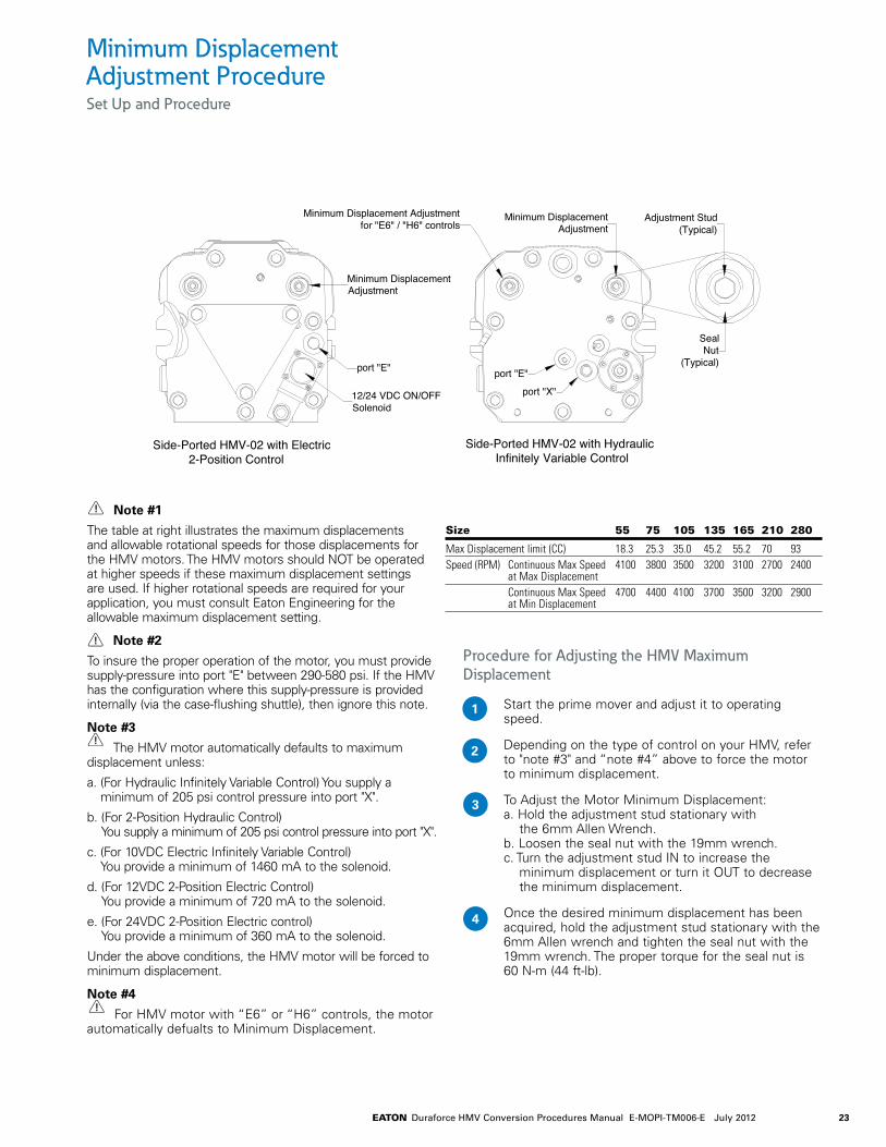
Minimum Displacement Adjustment ProcedureSet Up and Procedure
Note #1
The table at right illustrates the maximum displacements and allowable rotational speeds for those displacements for the HMV motors. The HMV motors should NOT be operated at higher speeds if these maximum displacement settings are used. If higher rotational speeds are required for your application, you must consult Eaton Engineering for the allowable maximum displacement setting.
Note #2
To insure the proper operation of the motor, you must provide supply-pressure into port "E" between 290-580 psi. If the HMV has the configuration where this supply-pressure is provided internally (via the case-flushing shuttle), then ignore this note.
Note #3
The HMV motor automatically defaults to maximum displacement unless:
a. (For Hydraulic Infinitely Variable Control) You supply a minimum of 205 psi control pressure into port "X".
b. (For 2-Position Hydraulic Control) You supply a minimum of 205 psi control pressure into port "X".
c. (For 10VDC Electric Infinitely Variable Control) You provide a minimum of 1460 mA to the solenoid.
d. (For 12VDC 2-Position Electric Control) You provide a minimum of 720 mA to the solenoid.
e. (For 24VDC 2-Position Electric control) You provide a minimum of 360 mA to the solenoid.
Under the above conditions, the HMV motor will be forced to minimum displacement.
Note #4
For HMV motor with “E6” or “H6” controls, the motor automatically defualts to Minimum Displacement.
Procedure for Adjusting the HMV Maximum Displacement
Start the prime mover and adjust it to operating speed.
Depending on the type of control on your HMV, refer to "note #3" and “note #4” above to force the motor to minimum displacement.
To Adjust the Motor Minimum Displacement: a. Hold the adjustment stud stationary with the 6mm Allen Wrench. b. Loosen the seal nut with the 19mm wrench. c. Turn the adjustment stud IN to increase the minimum displacement or turn it OUT to decrease the minimum displacement.
Once the desired minimum displacement has been acquired, hold the adjustment stud stationary with the 6mm Allen wrench and tighten the seal nut with the 19mm wrench. The proper torque for the seal nut is 60 N-m (44 ft-lb).
1
Size 55 75 105 135 165 210 280
Max Displacement limit (CC) 18.3 25.3 35.0 45.2 55.2 70 93Speed (RPM) Continuous Max Speed 4100 3800 3500 3200 3100 2700 2400 at Max Displacement Continuous Max Speed 4700 4400 4100 3700 3500 3200 2900 at Min Displacement
2
3
4
Minimum Displacement Adjustmentfor "E6" / "H6" controls
SealNut
(Typical)
port "X"
Adjustment Stud(Typical)
Minimum DisplacementAdjustment
Side-Ported HMV-02 with Electric2-Position Control
Side-Ported HMV-02 with HydraulicInfinitely Variable Control
port "E"port "E"
12/24 VDC ON/OFFSolenoid
Minimum DisplacementAdjustment
24 EATON Duraforce HMV Conversion Procedures Manual E-MOPI-TM006-E July 2012
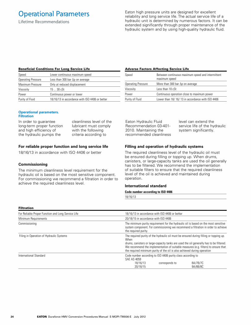
Operational ParametersLifetime Recommendations
Eaton high pressure units are designed for excellent reliability and long service life. The actual service life of a hydraulic unit is determined by numerous factors. It can be extended significantly through proper maintenance of the hydraulic system and by using high-quality hydraulic fluid.
Beneficial Conditions For Long Service Life
Speed Lower continuous maximum speedOperating Pressure Less than 300 bar Δp on averageMaximum Pressure Only at reduced displacementViscosity 15 ... 30 cStPower Continuous power or lowerPurity of Fluid 18/16/13 in accordance with ISO 4406 or better
Adverse Factors Affecting Service Life
Speed Between continuous maximum speed and intermittent maximum speed
Operating Pressure More than 300 bar Δp on average
Viscosity Less than 10 cSt
Power Continuous operation close to maximum power
Purity of Fluid Lower than 18/ 16/ 13 in accordance with ISO 4406
Filtration
For Reliable Proper Function and Long Service Life 18/16/13 in accordance with ISO 4406 or betterMinimum Requirements 20/18/15 in accordance with ISO 4406Commissioning The minimum purity requirement for the hydraulic oil is based on the most sensitive
system component. For commissioning we recommend a filtration in order to achieve the required purity.
Filing in Operation of Hydraulic Systems The required purity of the hydraulic oil must be ensured during filling or topping up. When drums, canisters or large-capacity tanks are used the oil generally has to be filtered. We recommend the implementation of suitable measures (e.g. filters) to ensure that the required minimum purity of the oil is also achieved during operation
International Standard Code number according to ISO 4406 purity class according to SAE AS 4059 18/16/13 corresponds to 8A/7B/7C 20/18/15 9A/8B/8C
Operational parameters. Filtration
In order to guarantee long-term proper function and high efficiency of the hydraulic pumps the
cleanliness level of the lubricant must comply with the following criteria according to
Eaton Hydraulic Fluid Recommendation 03-401-2010. Maintaining the recommended cleanliness
level can extend the service life of the hydraulic system significantly.
For reliable proper function and long service life
18/16/13 in accordance with ISO 4406 or better
Commissioning
The minimum cleanliness level requirement for the hydraulic oil is based on the most sensitive component. For commissioning we recommend a filtration in order to achieve the required cleanliness level.
Filling and operation of hydraulic systems
The required cleanliness level of the hydraulic oil must be ensured during filling or topping up. When drums, canisters, or large-capacity tanks are used the oil generally has to be filtered. We recommend the implementation of suitable filters to ensure that the required cleanliness level of the oil is achieved and maintained during operation.
International standard Code number according to ISO 440618/16/13

25EATON Duraforce HMV Conversion Procedures Manual E-MOPI-TM006-E July 2012
Operational ParametersPressure Fluids
In order to ensure the functional performance and high efficiency of the hydraulic motors the viscosity and purity of the operating fluid should meet the different operational requirements. Eaton recommends using only hydraulic fluids which are confirmed by the manufacturer as suitable for use in high pressure hydraulic installations or approved by the original equipment manufacturer.
• Mineral oil HLP to DIN 51 524-2
• Biodegradable fluids in accordance with ISO 15 380 on request
• Other pressure fluids on request
Eaton offers an oil testing service in accordance with VDMA 24 570 and the test apparatus required for in-house testing. Prices available on request.
Pressure Fluid Temperature Range [°C] -20 to +90
Working viscosity range [mm²/s] = [cSt] 10 to 80Optimum working viscosity [mm²/s] = [cSt] 15 to 30Max. viscosity (short time start up) [mm²/s] = [cSt] 1000
Permitted Pressure Fluids
Recommended Viscosity Ranges
Viscosity Recommendations
In order to be able to select the right hydraulic fluid it is necessary to know the working temperature in the hydraulic circuit. The hydraulic fluid should be selected such that its optimum viscosity is within
the working temperature range (see tables).
The temperature should not exceed 90°C (194°F) in any part of the system. Due to pressure and speed influences the
leakage fluid temperature is always higher than the circuit temperature. Please contact Eaton if the stated conditions cannot be met in special circumstances.
Working Temperature Viscosity Class
Temperature [mm²/s] = [cSt] at 40°C (104°F)
Approx. 30 to 40°C (86 to 104°F) 22Approx. 40 to 60°C (104 to 140°F) 32Approx. 60 to 80°C (140 to 176°F) 46 or 68
Further information regarding installation can be found in the operating instructions.

26 EATON Duraforce HMV Conversion Procedures Manual E-MOPI-TM006-E July 2012
Eaton Part NumbersHMV Variable Displacement Motors (Open & Closed Loop Operation)
Part # Description Qty
6003435526 Plug 10009630107 O-ring 1
Blocking Purge Valves p. 8
Part # Description Qty
0009630107 O-ring 16003451030 Valve Sleeve 16003450352 Valve Piston 10009210910 Compression Spring 19289003013 Shim, 0.5mm as req'd9289003010 Shim, 0.1mm as req'd6003435528 Screw Plug 1
Purge Valves - Open Loop p. 9
Part # Description Qty
0009630107 O-ring 16003451008 Valve Sleeve 19516003252 Ball 10009211007 Spring 19289003006 Shim, 0.5mm as req'd9289003003 Shim, 0.1mm as req'd6003435512 Screw Plug 1
Purge Valves - Closed Loop, 10 bar Standard p. 9
Part # Description Qty
0009630107 O-ring 16003451008 Valve Sleeve 19516003252 Ball 10009211007 Spring 19289003006 Shim, 0.5mm as req'd9289003003 Shim, 0.1mm as req'd6003435512 Screw Plug 16003454000 Orifice 1
Purge Valves - Closed Loop, 10 bar Reduced p. 9
Part # Description Qty
0009630107 O-ring 16003451008 Valve Sleeve 19516003252 Ball 10009211009 Spring 19289003006 Shim, 0.5mm as req'd9289003003 Shim, 0.1mm as req'd6003435512 Screw Plug 1
Purge Valves - Closed Loop, 14 bar Standard p. 9
Part # Description Qty
0009630107 O-ring 16003451008 Valve Sleeve 19516003252 Ball 10009211009 Spring 19289003006 Shim, 0.5mm as req'd9289003003 Shim, 0.1mm as req'd6003435512 Screw Plug 16003454000 Orifice 1
Purge Valves - Closed Loop, 14 bar Reduced p. 9

27EATON Duraforce HMV Conversion Procedures Manual E-MOPI-TM006-E July 2012
Eaton Part NumbersHMV Variable Displacement Motors (Open & Closed Loop Operation)
Part # Description Qty
0009211215 Spring 10009070203 Retaining Ring 12343433802 Spring Plate 12343433806 Spring Plate 12343430901 Bush 19289003014 Washer 12343450204 Pilot 10009211725 Spring 12343450301 Piston 10009210803 Spring 10009632157 O-ring 10009630231 O-ring 10009036848 Threaded Pin 19243281110 Lock Nut 19045341076 Cap Screw 40009620177 Screw Plug 12343412404 Cover, DIN Port 1
Control - Hydraulic Infinitely Variable, DIN Port p. 18 Control - Hydraulic Infinitely Variable, ISO Port p. 18
Part # Description Qty
0009211215 Spring 10009070203 Retaining Ring 12343433802 Spring Plate 12343433806 Spring Plate 12343430901 Bush 19289003014 Washer 12343450204 Pilot 10009211725 Spring 12343450301 Piston 10009210803 Spring 10009632157 O-ring 10009630231 O-ring 10009036848 Threaded Pin 19243281110 Lock Nut 19045341076 Cap Screw 40009620177 Screw Plug 12343412407 Cover, ISO Port 1
Part # Description Qty
Standard6003405642 Standard Shuttle 1Dampened6003405620 Dampened Shuttle 1Optimized6003405651 Optimized Shuttle 1
Shuttle Valves p. 10
28 EATON Duraforce HMV Conversion Procedures Manual E-MOPI-TM006-E July 2012
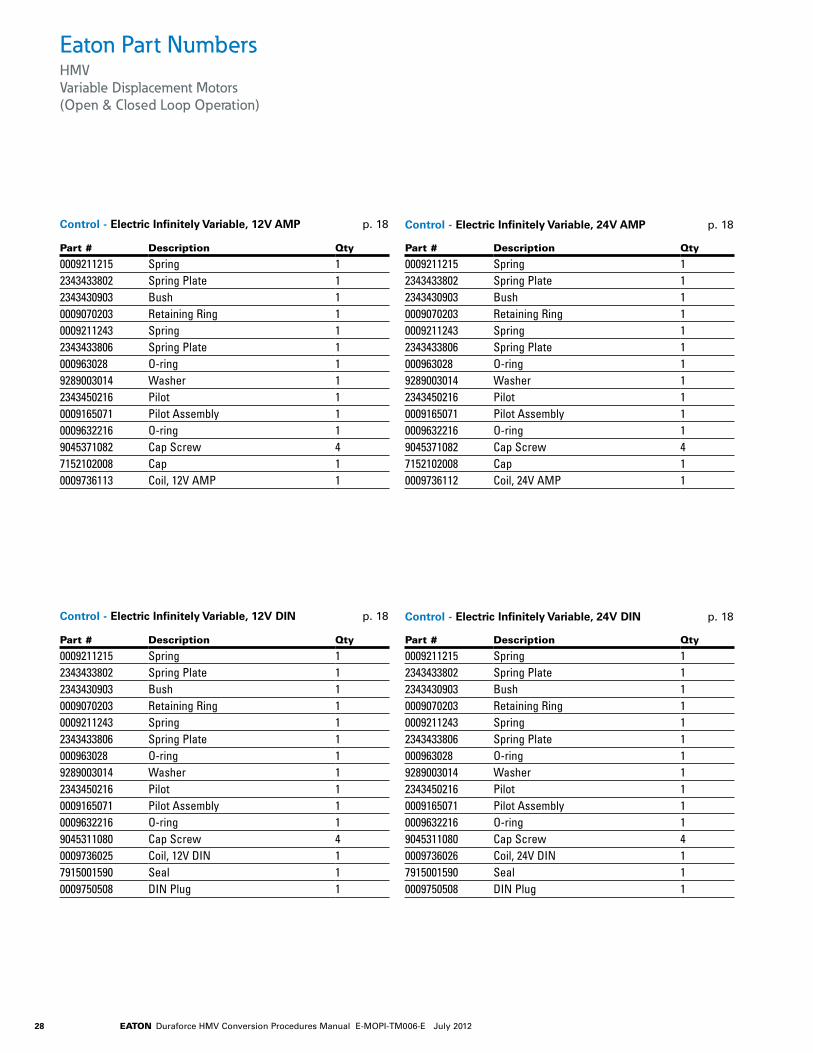
Eaton Part NumbersHMV Variable Displacement Motors (Open & Closed Loop Operation)
Part # Description Qty
0009211215 Spring 12343433802 Spring Plate 12343430903 Bush 10009070203 Retaining Ring 10009211243 Spring 12343433806 Spring Plate 1000963028 O-ring 19289003014 Washer 12343450216 Pilot 10009165071 Pilot Assembly 10009632216 O-ring 19045311080 Cap Screw 40009736025 Coil, 12V DIN 17915001590 Seal 10009750508 DIN Plug 1
Control - Electric Infinitely Variable, 12V DIN p. 18 Control - Electric Infinitely Variable, 24V DIN p. 18
Part # Description Qty
0009211215 Spring 12343433802 Spring Plate 12343430903 Bush 10009070203 Retaining Ring 10009211243 Spring 12343433806 Spring Plate 1000963028 O-ring 19289003014 Washer 12343450216 Pilot 10009165071 Pilot Assembly 10009632216 O-ring 19045311080 Cap Screw 40009736026 Coil, 24V DIN 17915001590 Seal 10009750508 DIN Plug 1
Part # Description Qty
0009211215 Spring 12343433802 Spring Plate 12343430903 Bush 10009070203 Retaining Ring 10009211243 Spring 12343433806 Spring Plate 1000963028 O-ring 19289003014 Washer 12343450216 Pilot 10009165071 Pilot Assembly 10009632216 O-ring 19045371082 Cap Screw 47152102008 Cap 10009736113 Coil, 12V AMP 1
Control - Electric Infinitely Variable, 12V AMP p. 18 Control - Electric Infinitely Variable, 24V AMP p. 18
Part # Description Qty
0009211215 Spring 12343433802 Spring Plate 12343430903 Bush 10009070203 Retaining Ring 10009211243 Spring 12343433806 Spring Plate 1000963028 O-ring 19289003014 Washer 12343450216 Pilot 10009165071 Pilot Assembly 10009632216 O-ring 19045371082 Cap Screw 47152102008 Cap 10009736112 Coil, 24V AMP 1
29EATON Duraforce HMV Conversion Procedures Manual E-MOPI-TM006-E July 2012
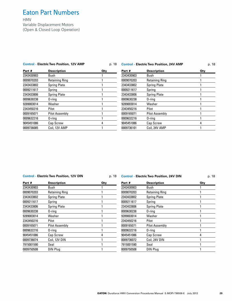
Eaton Part NumbersHMV Variable Displacement Motors (Open & Closed Loop Operation)
Part # Description Qty
2343430903 Bush 10009070203 Retaining Ring 12343433802 Spring Plate 10009211617 Spring 12343433806 Spring Plate 10009630238 O-ring 19289003014 Washer 12343450216 Pilot 10009165071 Pilot Assembly 10009632216 O-ring 19045451086 Cap Screw 40009736074 Coil, 12V DIN 17915001590 Seal 10009750508 DIN Plug 1
Control - Electric Two Position, 12V DIN p. 18 Control - Electric Two Position, 24V DIN p. 18
Part # Description Qty
2343430903 Bush 10009070203 Retaining Ring 12343433802 Spring Plate 10009211617 Spring 12343433806 Spring Plate 10009630238 O-ring 19289003014 Washer 12343450216 Pilot 10009165071 Pilot Assembly 10009632216 O-ring 19045451086 Cap Screw 40009736072 Coil, 24V DIN 17915001590 Seal 10009750508 DIN Plug 1
Part # Description Qty
2343430903 Bush 10009070203 Retaining Ring 12343433802 Spring Plate 10009211617 Spring 12343433806 Spring Plate 10009630238 O-ring 19289003014 Washer 12343450216 Pilot 10009165071 Pilot Assembly 10009632216 O-ring 19045451086 Cap Screw 40009736085 Coil, 12V AMP 1
Control - Electric Two Position, 12V AMP p. 18 Control - Electric Two Position, 24V AMP p. 18
Part # Description Qty
2343430903 Bush 10009070203 Retaining Ring 12343433802 Spring Plate 10009211617 Spring 12343433806 Spring Plate 10009630238 O-ring 19289003014 Washer 12343450216 Pilot 10009165071 Pilot Assembly 10009632216 O-ring 19045451086 Cap Screw 40009736101 Coil, 24V AMP 1

30 EATON Duraforce HMV Conversion Procedures Manual E-MOPI-TM006-E July 2012
Notes

31EATON Duraforce HMV Conversion Procedures Manual E-MOPI-TM006-E July 2012
Notes

EatonHydraulics Group USA14615 Lone Oak RoadEden Prairie, MN 55344USATel: 952-937-9800Fax: 952-294-7722www.eaton.com/hydraulics
EatonHydraulics Group EuropeRoute de la Longeraie 71110 MorgesSwitzerlandTel: +41 (0) 21 811 4600Fax: +41 (0) 21 811 4601
Eaton Hydraulics Group Asia PacificEaton BuildingNo.7 Lane 280 Linhong Road Changning District, Shanghai200335 ChinaTel: (+86 21) 5200 0099Fax: (+86 21) 2230 7240
© 2012 Eaton CorporationAll Rights Reserved Printed in USADocument No. E-MOPI-TM006-EJuly 2012