Service Manual - dms.hvacpartners.comdms.hvacpartners.com/docs/1009/Public/04/40GJQ-01SM.pdf ·...
52
Service Manual 40GJB / 40GJC / 40GJD / 40GJF 619KB / 619KC / 619KD / 619KF High Wall, Ducted, Cassette and Floor Console Multi---Zone Indoor units Sizes 09 to 24 TABLE OF CONTENTS PAGE SAFETY CONSIDERATIONS 1 ......................... INTRODUCTION 1 ................................... MODEL / SERIAL NUMBER NOMENCLATURES 2 ........ STANDARD FEATURES AND ACCESSORIES 3 ........... COMBINATION TABLES 4 ............................ PHYSICALDATA -- INDOOR 5 ......................... DIMENSIONS -- INDOOR 6 ............................ CLEARANCES -- INDOOR 11 .......................... ELECTRICAL DATA 13 ............................... WIRING 14 .......................................... WIRING DIAGRAMS 15 ............................... FAN AND MOTOR SPECIFICATIONS 18 ................. ENVIRONMENTAL SPECIFICATIONS 20 ................ AIRFLOW SPECIFICATIONS 20 ........................ AIRTHROW DATA 20 ................................. MAX STATIC PRESSURE -- DUCTED 20 ................. SYSTEM EVACUATION AND CHARGING 21 ............. MAIN LOGIC 22 ..................................... TROUBLESHOOTING 25 .............................. DIAGNOSIS AND SOLUTION 30 ....................... DISSASSEMBLY INSTRUCTIONS 38 .................... APPENDIX 49 ....................................... SAFETY CONSIDERATIONS Installing, starting up, and servicing air--conditioning equipment can be hazardous due to system pressures, electrical components, and equipment location (roofs, elevated structures, etc.). Only trained, qualified installers and service mechanics should install, start--up, and service this equipment. Untrained personnel can perform basic maintenance functions such as cleaning coils. All other operations should be performed by trained service personnel. When working on the equipment, observe precautions in the literature and on tags, stickers, and labels attached to the equipment. Follow all safety codes. Wear safety glasses and work gloves. Keep quenching cloth and fire extinguisher nearby when brazing. Use care in handling, rigging, and setting bulky equipment. Read this manual thoroughly and follow all warnings or cautions included in literature and attached to the unit. Consult local building codes and National Electrical Code (NEC) for special requirements. Recognize safety information. This is the safety--alert symbol ! ! . When you see this symbol on the unit and in instructions or manuals, be alert to the potential for personal injury. Understand these signal words: DANGER, WARNING, and CAUTION. These words are used with the safety--alert symbol. DANGER identifies the most serious hazards which will result in severe personal injury or death. WARNING signifies hazards which could result in personal injury or death. CAUTION is used to identify unsafe practices which may result in minor personal injury or product and property damage. NOTE is used to highlight suggestions which will result in enhanced installation, reliability, or operation. ! WARNING ELECTRICAL SHOCK HAZARD Failure to follow this warning could result in personal injury or death. Before installing, modifying, or servicing system, main electrical disconnect switch must be in the OFF position. There may be more than 1 disconnect switch. Lock out and tag switch with a suitable warning label. EXPLOSION HAZARD Failure to follow this warning could result in death, serious personal injury, and/or property damage. Never use air or gases containing oxygen for leak testing or operating refrigerant compressors. Pressurized mixtures of air or gases containing oxygen can lead to an explosion. ! WARNING CAUTION ! EQUIPMENT DAMAGE HAZARD Failure to follow this caution may result in equipment damage or improper operation. Do not bury more than 36 in. (914 mm) of refrigerant pipe in the ground. If any section of pipe is buried, there must be a 6 in. (152 mm) vertical rise to the valve connections on the outdoor units. If more than the recommended length is buried, refrigerant may migrate to the cooler buried section during extended periods of system shutdown. This causes refrigerant slugging and could possibly damage the compressor at start--up. INTRODUCTION This Service Manual provides the necessary information to service, repair, and maintain the 40GJ/619K family of heat pumps ; for service of the outdoor 38GJQ/538KR or the indoor 40GRQ/619FB, refer to the 38GJQ/538KR or 40GRQ/619FB service manual. Section 2 of this manual has an appendix with data required to perform troubleshooting. Use the Table of Contents to locate a desired topic.
Transcript of Service Manual - dms.hvacpartners.comdms.hvacpartners.com/docs/1009/Public/04/40GJQ-01SM.pdf ·...

Service Manual
40GJB / 40GJC / 40GJD / 40GJF619KB / 619KC / 619KD / 619KFHigh Wall, Ducted, Cassette and Floor Console Multi---Zone Indoor unitsSizes 09 to 24
TABLE OF CONTENTSPAGE
SAFETY CONSIDERATIONS 1. . . . . . . . . . . . . . . . . . . . . . . . .
INTRODUCTION 1. . . . . . . . . . . . . . . . . . . . . . . . . . . . . . . . . . .
MODEL / SERIAL NUMBER NOMENCLATURES 2. . . . . . . .
STANDARD FEATURES AND ACCESSORIES 3. . . . . . . . . . .
COMBINATION TABLES 4. . . . . . . . . . . . . . . . . . . . . . . . . . . .
PHYSICAL DATA -- INDOOR 5. . . . . . . . . . . . . . . . . . . . . . . . .
DIMENSIONS -- INDOOR 6. . . . . . . . . . . . . . . . . . . . . . . . . . . .
CLEARANCES -- INDOOR 11. . . . . . . . . . . . . . . . . . . . . . . . . .
ELECTRICAL DATA 13. . . . . . . . . . . . . . . . . . . . . . . . . . . . . . .
WIRING 14. . . . . . . . . . . . . . . . . . . . . . . . . . . . . . . . . . . . . . . . . .
WIRING DIAGRAMS 15. . . . . . . . . . . . . . . . . . . . . . . . . . . . . . .
FAN AND MOTOR SPECIFICATIONS 18. . . . . . . . . . . . . . . . .
ENVIRONMENTAL SPECIFICATIONS 20. . . . . . . . . . . . . . . .
AIRFLOW SPECIFICATIONS 20. . . . . . . . . . . . . . . . . . . . . . . .
AIRTHROW DATA 20. . . . . . . . . . . . . . . . . . . . . . . . . . . . . . . . .
MAX STATIC PRESSURE -- DUCTED 20. . . . . . . . . . . . . . . . .
SYSTEM EVACUATION AND CHARGING 21. . . . . . . . . . . . .
MAIN LOGIC 22. . . . . . . . . . . . . . . . . . . . . . . . . . . . . . . . . . . . .
TROUBLESHOOTING 25. . . . . . . . . . . . . . . . . . . . . . . . . . . . . .
DIAGNOSIS AND SOLUTION 30. . . . . . . . . . . . . . . . . . . . . . .
DISSASSEMBLY INSTRUCTIONS 38. . . . . . . . . . . . . . . . . . . .
APPENDIX 49. . . . . . . . . . . . . . . . . . . . . . . . . . . . . . . . . . . . . . .
SAFETY CONSIDERATIONSInstalling, starting up, and servicing air--conditioning equipmentcan be hazardous due to system pressures, electrical components,and equipment location (roofs, elevated structures, etc.).
Only trained, qualified installers and service mechanics shouldinstall, start--up, and service this equipment.
Untrained personnel can perform basic maintenance functions suchas cleaning coils. All other operations should be performed bytrained service personnel.
When working on the equipment, observe precautions in theliterature and on tags, stickers, and labels attached to theequipment.
Follow all safety codes. Wear safety glasses and work gloves. Keepquenching cloth and fire extinguisher nearby when brazing. Usecare in handling, rigging, and setting bulky equipment.
Read this manual thoroughly and follow all warnings or cautionsincluded in literature and attached to the unit. Consult local buildingcodes and National Electrical Code (NEC) for special requirements.
Recognize safety information. This is the safety--alert symbol !! .When you see this symbol on the unit and in instructions or manuals,be alert to the potential for personal injury. Understand these signalwords: DANGER, WARNING, and CAUTION.
These words are used with the safety--alert symbol. DANGERidentifies the most serious hazards which will result in severe
personal injury or death. WARNING signifies hazards which couldresult in personal injury or death. CAUTION is used to identifyunsafe practices which may result in minor personal injury orproduct and property damage.
NOTE is used to highlight suggestions which will result inenhanced installation, reliability, or operation.
! WARNINGELECTRICAL SHOCK HAZARD
Failure to follow this warning could result in personalinjury or death.
Before installing, modifying, or servicing system, mainelectrical disconnect switch must be in the OFFposition. There may be more than 1 disconnect switch.Lock out and tag switch with a suitable warning label.
EXPLOSION HAZARD
Failure to follow this warning couldresult in death, serious personal injury,and/or property damage.
Never use air or gases containingoxygen for leak testing or operatingrefrigerant compressors. Pressurizedmixtures of air or gases containingoxygen can lead to an explosion.
! WARNING
CAUTION!
EQUIPMENT DAMAGE HAZARD
Failure to follow this caution may result in equipmentdamage or improper operation.
Do not bury more than 36 in. (914 mm) of refrigerant pipein the ground. If any section of pipe is buried, there must bea 6 in. (152 mm) vertical rise to the valve connections onthe outdoor units. If more than the recommended length isburied, refrigerant may migrate to the cooler buried sectionduring extended periods of system shutdown. This causesrefrigerant slugging and could possibly damage thecompressor at start--up.
INTRODUCTIONThis Service Manual provides the necessary information to service,repair, and maintain the 40GJ/619K family of heat pumps ; for serviceof the outdoor 38GJQ/538KR or the indoor 40GRQ/619FB, refer tothe 38GJQ/538KR or 40GRQ/619FB service manual. Section 2 ofthis manual has an appendix with data required to performtroubleshooting. Use the Table of Contents to locate a desired topic.

2
MODEL / SERIAL NUMBER NOMENCLATURES
BQ D
B=ALL
SYSTEM TYPEQ = HEAT PUMP
NOT USED
INDOOR UNIT
40 GJ 309
40 = FAN COIL UNIT
GJ = CASSETTE, DUCTED, FLOOR CONSOLE, HIGHWALL VOLTAGE3 = 208/230---1---60
NOMINAL CAPACITY09 --- 3/4TON12 --- 1TON18 --- 1--- 1/2TONS21 --- 1--- 3/4TONS24 --- 2TONS
INDOOR FAN COIL TYPE
B= HIGHWALLH= HIGHWALL (WHITE COLOR 40GRQ)C = CASSETTED = DUCTEDF = FLOOR CONSOLE
--- ---
01 15
Week of Manufacture
Year of Manufacture
10001
Sequential Serial Number
V
V = ALL MODELS
Use of the AHRI CertifiedTM Mark indicates amanufacturer’s participation in the program For verification of certification for individual products, go to www.ahridirectory.org.
QE B
SYSTEM TYPEQ = HEAT PUMP
VOLTAGEE = 208---230/1/60
INDOOR UNIT
619 F GA009
619 = FAN COIL UNIT
F/K = MODELGA = ALL MODELS
NOMINAL CAPACITY009 --- 3/4TON012 --- 1TON018 --- 1---1/2TONS021 --- 1---3/4TONS024 --- 2TONS
INDOOR FAN COIL TYPE
B = HIGHWALLC = CASSETTED = DUCTEDF = FLOOR CONSOLE
B
MAXIMUM NUMBER OF FAN COIL UNITS THATCAN BE CONNECTED TO THE OUTDOOR UNITB=1:1

3
STANDARD FEATURES AND ACCESSORIESTable 1—Standard Features and Accessories
Ease of InstallationMounting Bracket SLow Voltage Controls SComfort FeaturesMicroprocessor Control SWired Remote Control for High Walls, Cassette and Floor Console AWired Remote Control for Ducted SWireless Remote Control SRapid Cooling and Heating SAutomatic Air Sweep SCold Blow Prevention SContinuous Fan SAuto Restart Function SAuto Changeover SFollow Me SEnergy Saving FeaturesInverter Driven Compressor SSleep Mode S24 Hour Stop/Start Timer S46° F Heating Mode (Heating Setback) SSafety And ReliabilityIndoor Coil Freeze Protection S3 Minute Time Delay For Compressor SHigh Compressor Discharge Temperature SLow Voltage Protection SCompressor Overload Protection SCompressor Over Current Protection SIPM Module Protection SEase of ServiceCleanable Filters SDiagnostic SError Messages Displayed On Front Panel SApplication FlexibilityCondensate Pumps For High Walls and Floor Console ACondensate Pump For Cassette and Ducted SCrankcase Heater SBase pan Heater SLegendS StandardA Accessory
INDOOR UNITS
Fig. 1 – Condensate Pump Accessory
On high wall and floor console fan coils, the condensate pumpaccessory is recommended when adequate drain line pitch cannotbe provided, or when the condensate must move up to exit.The pump has a lift capability of 12 ft. (3.6 m) on the dischargeside if the pump is mounted in the fan coil or 6 ft (1.8 m) on thesuction side if the pump is remote mounted.
OUTDOOR UNITSCRANKCASE HEATERStandard on all unit sizes. Heater clamps around compressor oilstump.

4
COMBINATION TABLESTable 2—Combination
Indoor Unit Nominal Unit Btuh Indoor Model Number Indoor Model Number Outdoor Model Number Outdoor Model Number
High Wall(40GRQ/619FB)
9,000 40GRQB09B--3 619FEQ009BBGA
38GJQC18---338GJQD24---3
538KEQ018RCGA538KEQ024RDGA
12,000 40GRQB12B--3 619FEQ012BBGA18,000 40GRQB18B--3 619FEQ018BBGA9,000 40GRQB09H--3 619FEQ009HBGA12,000 40GRQB12H--3 619FEQ012HBGA18,000 40GRQB18H--3 619FEQ018HBGA
High Wall(40GJB/619KB)
9,000 40GJQB09B--3 619KEQ009BBGA12,000 40GJQB12B--3 619KEQ012BBGA18,000 40GJQB18B--3 619KEQ018BBGA
Cassette12,000 40GJQB12C--3 619KEQ012CBGA18,000 40GJQB18C--3 619KEQ018CBGA
Ducted9,000 40GJQB09D--3 619KEQ009DBGA12,000 40GJQB12D--3 619KEQ012DBGA18,000 40GJQB18D--3 619KEQ018DBGA
Floor Console9,000 40GJQB09F--3 619KEQ009FBGA12,000 40GJQB12F--3 619KEQ012FBGA18,000 40GJQB18F--3 619KEQ018FBGA
Table 3—CombinationIndoor Unit Nominal Unit Btuh Indoor Model Number Indoor Model Number Outdoor Model Number Outdoor Model Number
High Wall(40GRQ/619FB)
9,000 40GRQB09B--3 619FEQ009BBGA
38GJQF30---338GJQG36---338GJQG42---3
538KEQ030RFGA538KEQ036RGGA538KEQ042RGGA
12,000 40GRQB12B--3 619FEQ012BBGA
18,000 40GRQB18B--3 619FEQ018BBGA
9,000 40GRQB09H--3 619FEQ009HBGA
12,000 40GRQB12H--3 619FEQ012HBGA
18,000 40GRQB18H--3 619FEQ018HBGA
High Wall(40GJB/619KB)
9,000 40GJQB09B--3 619KEQ009BBGA
12,000 40GJQB12B--3 619KEQ012BBGA
18,000 40GJQB18B--3 619KEQ018BBGA
24,000 40GJQB24B--3 619KEQ024BBGA
Cassette
12,000 40GJQB12C--3 619KEQ012CBGA
18,000 40GJQB18C--3 619KEQ018CBGA
24,000 40GJQB24C--3 619KEQ024CBGA
Ducted
9,000 40GJQB09D--3 619KEQ009DBGA
12,000 40GJQB12D--3 619KEQ012DBGA
18,000 40GJQB18D--3 619KEQ018DBGA
21,000 40GJQB21D--3 619KEQ021DBGA
24,000 40GJQB24D--3 619KEQ024DBGA
Floor Console
9,000 40GJQB09F--3 619KEQ009FBGA
12,000 40GJQB12F--3 619KEQ012FBGA
18,000 40GJQB18F--3 619KEQ018FBGA
Table 4—CombinationIndoor Unit Nominal Unit Btuh Indoor Model Number Indoor Model Number Outdoor Model Number Outdoor Model Number
High Wall(40GRQ/619FB)
9,000 40GRQB09B--3 619FEQ009BBGA
38GJQK48---338GJQL56---3
538KEQ048RKGA538KEQ056RLGA
12,000 40GRQB12B--3 619FEQ012BBGA
18,000 40GRQB18B--3 619FEQ018BBGA
9,000 40GRQB09H--3 619FEQ009HBGA
12,000 40GRQB12H--3 619FEQ012HBGA
18,000 40GRQB18H--3 619FEQ018HBGA
High Wall(40GJB/619KB)
9,000 40GJQB09B--3 619KEQ009BBGA
12,000 40GJQB12B--3 619KEQ012BBGA
18,000 40GJQB18B--3 619KEQ018BBGA
24,000 40GJQB24B--3 619KEQ024BBGA
Cassette
12,000 40GJQB12C--3 619KEQ012CBGA
18,000 40GJQB18C--3 619KEQ018CBGA
24,000 40GJQB24C--3 619KEQ024CBGA
Ducted
9,000 40GJQB09D--3 619KEQ009DBGA
12,000 40GJQB12D--3 619KEQ012DBGA
18,000 40GJQB18D--3 619KEQ018DBGA
21,000 40GJQB21D--3 619KEQ021DBGA
24,000 40GJQB24D--3 619KEQ024DBGA
Floor Console
9,000 40GJQB09F--3 619KEQ009FBGA
12,000 40GJQB12F--3 619KEQ012FBGA
18,000 40GJQB18F--3 619KEQ018FBGA
5
PHYSICAL DATA -- INDOORTable 5—Indoor High Wall (40GRQ/619FB)
IndoorHigh Wall40GRQ/619FB
Size 9 12 18
Model (White)40GRQB09H--3619FEQ009HBGA
40GRQB12H--3619FEQ012HBGA
40GRQB18H--3619FEQ018HBGA
Model (Silver)40GRQB09B--3619FEQ009BBGA
40GRQB12B--3619FEQ012BBGA
40GRQB18B--3619FEQ018BBGA
Unit Width In. 37.8 37.8 37.8
Unit Height In. 12.6 12.6 12.6
Unit Depth In. 8.1 8.1 8.1
Net Weight Lbs. 30.9 30.9 30.9
Pipe Connection Size - Liquid In. 1/4" 1/4" 1/4"
Pipe Connection Size - Suction In. 1/2" 1/2" 5/8"
Number of Fan Speeds 7 7 7
Airflow (lowest to highest) CFM 206/235/294/324/353/383/412 265/294/353/383/412/441/471 324/353/412/441/471/500/530
Sound Pressure (lowest to highest) dB(A) 22/24/26/30/34/38/41 23/25/27/31/35/39/42 26/28/31/35/39/43/48
Wireless Remote Controller (°F/°C Convertible) Standard
Wired Remote Controller (°F/°C Convertible) Not Available
Table 6—Indoor High Wall (40GJB/619KB)
IndoorHigh Wall
40GJB/619KB
Size 9 12 18 24
Model40GJQB09B--3619KEQ009BBGA
40GJQB12B--3619KEQ012BBGA
40GJQB18B--3619KEQ018BBGA
40GJQB24B--3619KEQ024BBGA
Unit Width In. 34.1 34.1 40.1 46.4
Unit Height In. 11.5 11.5 12.6 2.8
Unit Depth In. 8.2 8.2 9.1 10.4
Net Weight Lbs. 24.3 24.3 30.9 38.6
Pipe Connection Size - Liquid In. 1/4" 1/4" 1/4" 1/4"
Pipe Connection Size - Suction In. 1/2" 1/2" 5/8" 5/8"
Number of Fan Speeds 7 7 7 7
Airflow (lowest to highest) CFM 224/241/271/312/359/394/430 224/241/271/312/659/394/453 282/330/371/418/465/512/589 294/353/412/471/530/588/647
Sound Pressure (lowest to highest) dB(A) 23/26/30/34/36/38/42 24/26/30/34/36/38/44 33/36/38/41/44/47/51 38/41/43/45/47/49/52
Wireless Remote Controller (°F/°CConvertible)
Standard
Wired Remote Controller (°F/°C Convertible) Optional
Table 7—Indoor Cassette
IndoorCassette
Size 12 18 24
Model40GJQB12C--3619KEQ012CBGA
40GJQB18C--3619KEQ018CBGA
40GJQB24C--3619KEQ024CBGA
Unit Width In. 22.4 22.4 22.4
Unit Height In. 9.1 9.1 9.4
Unit Depth In. 22.4 22.4 33.1
Net Weight Lbs. 39.7 39.7 61.7
Pipe Connection Size - Liquid In. 1/4" 1/4" 3/8"
Pipe Connection Size - Suction In. 3/8" 1/2" 5/8"
Number of Fan Speeds 3 3 3
Airflow CFM 265/294/353 265/294/353 500/ 559/694
Sound Pressure (lowest to highest) dB(A) 42/44/46 42/44/46 35/37/39
Wireless Remote Controller (°F/°C Convertible) Standard
Wired Remote Controller (°F/°C Convertible) Standard
Table 8—Indoor Ducted
IndoorDucted
Size 9 12 18 21 24
Model40GJQB09D--3619KEQ009DBGA
40GJQB12D--3619KEQ012DBGA
40GJQB18D--3619KEQ018DBGA
40GJQB21D--3619KEQ021DBGA
40GJQB24D--3619KEQ024DBGA
Unit Width In. 24.2 24.2 24.2 24.2 24.2
Unit Height In. 7.9 7.9 7.9 7.9 7.9
Unit Depth In. 27.6 27.6 35.4 43.3 43.3
Net Weight Lbs. 48.5 50.7 59.5 68.3 68.3
Pipe Connection Size - Liquid In. 1/4" 1/4" 1/4" 3/8" 3/8"
Pipe Connection Size - Suction In. 3/8" 3/8" 1/2" 5/8" 5/8"
Number of Fan Speeds 3 3 3 3 3
Airflow (lowest to highest) CFM 147/176/264 176/235/323 294/353/411 323/441/588 323/441/588
Sound Pressure (lowest to highest) dB(A) 31/34/37 32/35/39 33/37/41 34/38/42 34/38/42
Max Static Pressure In.WG. 0.04 0.04 0.04 0.06 0.06
Wireless Remote Controller (°F/°C Convertible) Standard
Wired Remote Controller (°F/°C Convertible) Standard
Table 9—Indoor Floor Console
IndoorFloor
Console
Size 9 12 18
Model40GJQB09F--3619KEQ009FBGA
40GJQB12F--3619KEQ012FBGA
40GJQB18F--3619KEQ018FBGA
Unit Width In. 8.5 8.5 8.5
Unit Height In. 23.6 23.6 23.6
Unit Depth In. 27.6 27.6 27.6
Net Weight Lbs. 33.1 33.1 33.1
Pipe Connection Size - Liquid In. 1/4" 1/4" 1/4"
Pipe Connection Size - Suction In. 3/8" 3/8" 1/2"
Number of Fan Speeds 7 7 7
Airflow (lowest to highest) CFM 188/217/253/282/311/ 329/ 382 205/ 264/294/ 323/353/ 382/441 241/311/ 341/ 382/ 423/470/ 494
Sound Pressure (lowest to highest) dB(A) 25/ 26/ 30/ 33/ 36/ 38/ 40 27/ 32/ 35/ 37/ 38/ 40/43 33/ 35/ 37/ 41/ 44/ 46/ 48
Wireless Remote Controller (°F/°C Convertible) Standard
Wired Remote Controller (°F/°C Convertible) Not Available

6
DIMENSIONS -- INDOOR
Fig. 2 – 40GJB/619KB High Wall Dimensions
Table 10—40GJB/619KB High Wall
Dimensions In. (mm)Operating Weight Lbs.
(kg)Unit Size W D H
9K 34.1 (866) 8.2 (209) 11.5 (292) 24.3 (11)12K 34.1 (866) 8.2 (209) 11.5 (292) 24.3 (11)18K 40.1 (1018) 9.1 (230) 12.6 (320) 30.9 (14)24K 46.4 (1178) 10.4 (264) 12.8 (325) 38.6 (17.5)

7
DIMENSIONS -- INDOOR (CONTINUED)
Fig. 3 – Cassette Grill Dimensions
Fig. 4 – Cassette Side View Dimensions
8
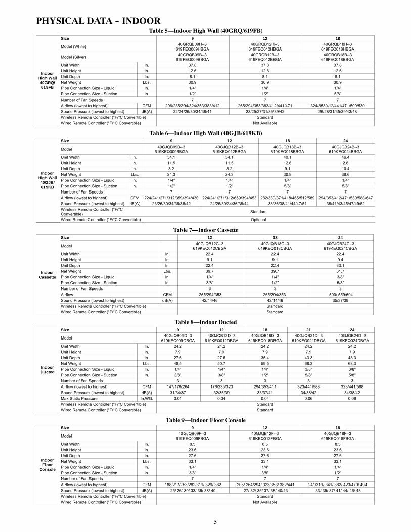
DIMENSIONS -- INDOOR (CONTINUED)
Fig. 5 – Cassette Connection Side View Dimensions
Fig. 6 – Cassette Top View Dimensions

9
DIMENSIONS -- INDOOR (CONTINUED)
Fig. 7 – Ducted Dimensions
Table 11—Dimensions
Dimensions In. (mm) OperatingWeight
Lbs. (kg)Unit Size A B C D E F G H I J
9K29.2(742)
19.3(491)
26.1(662)
24.4(620)
27.6(700)
24.2(615)
30.8(782)
6.1(156)
7.9(200)
25(635)
48.5(22)
12K29.2(742)
19.3(491)
26.1(662)
24.4(620)
27.6(700)
24.2(615)
30.8(782)
6.1(156)
7.9(200)
25(635)
50.7(23)
18K37.1(942)
19.3(491)
33.9(862)
32.3(820)
35.4(900)
24.2(615)
38.7(982)
6.1(156)
7.9(200)
25(635)
59.5(27)
21K45
(1142)19.3(491)
41.8(1062)
40.2(1020)
43.3(1100)
24.2(615)
46.5(1182)
6.1(156)
7.9(200)
25(635)
68.3(31)
24K45
(1142)19.3(491)
41.8(1062)
40.2(1020)
43.3(1100)
24.2(615)
46.5(1182)
6.1(156)
7.9(200)
25(635)
68.3(31)

10
DIMENSIONS -- INDOOR (CONTINUED)
Fig. 8 – Floor Console Dimensions

11
CLEARANCES -- INDOOR
6" (0.15m) min.
5"(0.13m)
min.
6'
5"(0.13m)
min.
(1.8m)
CEILING
FLOOR
Fig. 9 – 40GRQ/619FB and 40GJB/619KB High Wall Clearance
Fig. 10 – Cassette Clearance
12
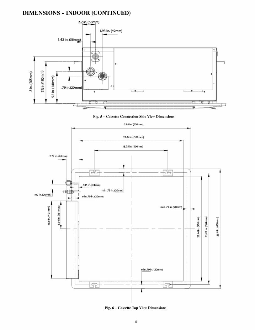
CLEARANCES -- INDOOR (CONTINUED)
Fig. 11 – Ducted Clearance
Fig. 12 – Floor Console Clearance

13
ELECTRICAL DATATable 12—40GRQ/619FB High Wall
UNIT SIZESYSTEM VOLTAGE OPERATING VOLTAGE INDOOR FANVOLT / PHASE / HZ MAX / MIN V-PH-HZ FLA HP W
9208-230/1/60 253 / 187 208-230/1/60
0.1 0.0268 2012 0.1 0.0268 2018 0.1 0.0268 20
Table 13—40GJB/619KB High Wall
UNIT SIZESystem Voltage OPERATING VOLTAGE INDOOR FAN
VOLT / PHASE / HZ MAX / MIN V-PH-HZ FLA HP W9
208-230/1/60 253 / 187 208-230/1/60
0.17 1/72 1012 0.17 1/72 1018 0.3 1/29 2524 0.38 1/10 70
Table 14—Cassette
UNIT SIZESystem Voltage OPERATING VOLTAGE INDOOR FAN
VOLT / PHASE / HZ MAX / MIN V-PH-HZ FLA HP W12
208-230/1/60 253 / 187 208-230/1/600.18 1/72 46
18 0.18 1/72 4624 0.43 1/20 46
Table 15—Ducted
UNIT SIZESystem Voltage OPERATING VOLTAGE INDOOR FAN
VOLT / PHASE / HZ MAX / MIN V-PH-HZ FLA HP W9
208-230/1/60 253 / 187 208-230/1/60
0.28 1/24 8012 0.31 1/18 8018 0.41 1/12 10021 0.5 1/36' 12424 0.5 1/36' 124
Table 16—Floor Console
UNIT SIZESystem Voltage OPERATING VOLTAGE INDOOR FAN
VOLT / PHASE / HZ MAX / MIN V-PH-HZ FLA HP W9
208-230/1/60 253 / 187 208-230/1/600.14 1/24 30
12 0.14 1/24 3018 0.14 1/24 30
*Permissible limits of the voltage range at which the unit will operate satisfactorily.LEGENDFLA --- Full Load AmpsMCA --- Minimum Circuit AmpsRLA --- Rated Load Amps

14
WIRING
CAUTION!EQUIPMENT DAMAGE HAZARD
Failure to follow this caution may result in equipmentdamage or improper operation.
S Wires should be sized based on NEC and local codes.
S Use copper conductors only with a minimum 300 volt .rating and 2/64 inch thick insulation.
CAUTION!
EQUIPMENT DAMAGE HAZARD
Failure to follow this caution may result in equipment damageor improper operation.SBe sure to comply with local codes while running wire fromindoor unit to outdoor unit.
SEvery wire must be connected firmly. Loose wiring maycause terminal to overheat or result in unit malfunction. Afire hazard may also exist. Therefore, be sure all wiring istightly connected.
SNo wire should be allowed to touch refrigerant tubing,compressor or any moving parts.
SDisconnecting means must be provided and shall be locatedwithin sight and readily accessible from the air conditioner.
SConnecting cable with conduit shall be routed through hole inthe conduit panel.
All wires must be sized per NEC (National Electrical Code) orCEC (Canadian Electrical Code) and local codes. Use ElectricalData table MCA (minimum circuit amps) and MOCP (maximumover current protection) to correctly size the wires and thedisconnect fuse or breakers respectively.
Per caution note, only copper conductors with a minimum 300volt rating and 2/64--inch thick insulation must be used. The useof BX cable is not recommended.
SIZES 18--42Recommended Connection Method for Power andCommunication --Wiring -- Power and Communication Wiring:
The main power is supplied to the outdoor unit. The field supplied14/3 power/communication wiring from the outdoor unit to indoorunit consists of four (4) wires and provides the power for theindoor unit. Two wires are high voltage AC power; one iscommunication wiring and the other is a ground wire.
Recommended Connection Method for Power andCommunication Wiring (To minimize communication wiringinterference)
Power Wiring:
The main power is supplied to the outdoor unit. The field suppliedpower wiring from the outdoor unit to indoor unit consists of three (3)wires and provides the power for the indoor unit. Two wires are highvoltage AC power and one is a ground wire. To minimize voltagedrop, the factory recommended wire size is 14/3 stranded with aground.
Communication Wiring:
A separate shielded copper conductor, with a minimum 300 voltrating and 2/64--inch thick insulation, must be used as thecommunication wire from the outdoor unit to the indoor unit.Please use a separate shielded 16GA stranded control wire.
FOR SIZES 48--56Recommended Connection Method for Power andCommunication --Wiring -- Power and Communication Wiring:Power Wiring OUTDOOR UNIT& BRANCH BOXES:
Separate power supplies are required for the outdoor unit and theBranch Boxes. The indoor units are powered from the Branch Boxes.The field supplied 14/3 power wiring from the OUTDOOR UNITconsists of three (3) wires. Two wires are high voltage AC power, oneis a ground wire.The field supplied 14/3 power wiring from the BRANCH BOXESconsists of three (3) wires. Two wires are high voltage AC power, oneis a ground wire.Up to three (3) Branch Boxes can be powered from the same 15 ampbreaker.
Communication Wiring:
A separate shielded copper conductor only, with a minimum 300 voltrating and 2/64--inch thick insulation, must be used as thecommunication wire from the OUTDOOR UNIT to the BRANCHBOX.Please use a separate shielded 16GA stranded control wire.Power and Communication Wiring BRANCH BOXES toINDOOR UNITS:The field supplied 14/3 power/communication wiring from theBRANCH BOX to the INDOOR UNIT consists of four (4) wiresand provides the power for the indoor unit. Two wires are highvoltage AC power, one is communication wiring “2” and the other isa ground wire “N(1)”See diagram below for details on wiring for sizes 48--56.
Fig. 13 – Wiring Connection

15
WIRING DIAGRAMS
Fig. 14 – Wiring Diagrams 40GRQ/619FB High Wall 9k, 12k and 18k
Fig. 15 – Wiring Diagrams 40GJB/619KB High Wall 9k, 12k, 18k and 24k

16
Fig. 16 – Wiring Diagram Cassette 12k, 18k
Fig. 17 – Wiring Diagram Cassette 24k

17
Fig. 18 – Wiring Diagram Ducted 9k, 12k, 18, 21k and 24k
Fig. 19 – Wiring Diagrams Floor Console 9k, 12k and 18k

18
FAN AND MOTOR SPECIFICATIONSTable 17—40GRQ/619FB High Wall
System size 9 12 18Voltage 208/230-1-60 208/230-1-60 208/230-1-60
Indoorfan Type Cross-flow Cross-flow Cross-flow
Diameter in 4 1/5 4 1/5 4 1/5
Height in 27 1/2 27 1/2 27 1/2
Indoorfanmotor
Type DC DC DC
Phase 3 3 3FLA 0.1 0.1 0.1
Insulation class Class E Class E Class E
Safe class IP20 IP20 IP20
Output W 20 20 20Rated current Amps 0.1 0.1 0.1Rated HP HP 0.0268 0.0268 0.0268Speed rev/min
Rated RPM rev/min 1250 1250 1250
Table 18—40GJB/619KB High WallSystem size 9 12 18 24
Voltage 208/230-1-60 208/230-1-60 208/230-1-60 208/230-1-60
Indoorfan Type Cross-Flow Cross-Flow Cross-Flow Cross-Flow
Diameter in 3.85 3.85 3-15/16 4 1/6
Height in 26-1/16 26-1/16 30.12 35
Indoorfanmotor
Type Direct Drive Direct Drive Direct Drive Direct DrivePhase 1 1 1 1FLA 0.17 0.17 0.3 0.38
Insulation class E E E ESafe class IP41 IP41 IP41 IP20Output W 10 10 25 70
Rated current Amps 0.07 0.07 0.1 0.28Rated HP HP 1/72 1/72 1/29 1/10Speed rev/min 1400 1400 1350 1500
Rated RPM rev/min 1400 1400 1350 1500
Table 19—CassetteSystem size 12 18 24
Voltage 208/230-1-60 208/230-1-60 208/230-1-60
Outdoor
Fan
Type Centrifugal Axial-flow Centrifugal
Diameter in 11.1 11.1 17.7
Height in 5.8 5.8 4.4
Indoorfanmotor
ModelType Direct Drive Direct Drive Direct DrivePhase 1 1 1FLA .18 .18 .43
Insulation class B B BSafe class IP20 IP20 IP20Input W 50 50 100Output W 11 11 35
Rated current Amps .23 .23 .43Capacitor µF 1 1 3Rated HP HP 1/72 1/72 1/20Speed rev/min 845 845 620
Rated RPM rev/min 845 845 620

19
FAN AND MOTOR SPECIFICATIONS (CONT)Table 20—Ducted
System size 9 12 18 21 24Voltage 208/230-1-60 208/230-1-60 208/230-1-60 208/230-1-60 208/230-1-60
Indoorfan Type Centrifugal Centrifugal Centrifugal Centrifugal Centrifugal
Diameter in 5.49 5.49 5.49 5.49 5.49
Height in 5.3 5.3 5.3 5.3 5.3
Indoorfanmotor
Type Direct Drive Direct Drive Direct Drive Direct Drive Direct DrivePhase 1 1 1 1 1FLA 0.28 0.31 0.41 0.5 0.5
Insulation class B B B B BSafe class IP20 IP20 IP20 IP20 IP20Input W 80 80 100 124 124Output W 30 40 60 20 20
Rated current Amps 0.35 0.35 0.43 0.54 0.54Capacitor µF 1.5 3 3 3 3Rated HP HP 1/24 1/18 1/12 1/36 1/36Speed rev/min 970 960 920 985 985
Rated RPM rev/min 970 960 950 985 985
Table 21—Floor ConsoleSystem size 9 12 18
Voltage 208/230-1-60 208/230-1-60 208/230-1-60
Indoorfan Type Centrifugal Centrifugal Centrifugal
Diameter in 14.5 14.5 14.5
Height in 3.15 3.15 3.15
Indoorfanmotor
Type Direct Drive Direct Drive Direct DrivePhase 1 1 1FLA .14 .14 .14
Insulation class E E ESafe class IP20 IP20 IP20Output W 30 30 30
Rated current Amps .14 .14 .14Rated HP HP 1/24 1/24 1/24Speed rev/min 650 750 840
Rated RPM rev/min 650 750 840

20
ENVIRONMENTAL SPECIFICATIONSTable 22—Environmental Specifications
Cooling Operating RangeIndoor Min - Max DB °F 64-95
Indoor Min - Max WB °F 55
Heating Operating Range Indoor Min –Max DB °F 32~86
Non-operating environment Temperature range (DB) °F 32~86
Operation Humidity dBa 0~80%
Ambient Humidity % 0~80%
AIRFLOW SPECIFICATIONSTable 23—40GJB/619KB High Wall
System size 9 12 18 24
IndoorAirflow
SS CFM 430 453 589 647H CFM 394 394 512 588MH CFM 359 659 465 530M CFM 312 312 418 471ML CFM 271 271 371 412L CFM 241 241 330 353SL CFM 224 224 282 294
Table 24—CassetteSystem size 12 18 24
IndoorAirflow H CFM 353 353 694
M CFM 294 294 559
L CFM 265 265 500
Table 25—Floor ConsoleSystem size 9 12 18
IndoorAirflow
SS CFM 382 441 494H CFM 329 382 470MH CFM 311 353 423M CFM 282 323 382ML CFM 253 294 341L CFM 217 264 311SL CFM 188 205 241
Table 26—DuctedSystem size 9 12 18 21 24
IndoorAirflow H CFM 264 323 411 588 588
M CFM 176 235 353 441 441
L CFM 147 176 294 323 323
AIR THROW DATATable 27—40GJB/619KB High Wall
System size 9 12 18 24SH Ft. 27.2 28.9 28.9 30.2
Table 28—Floor ConsoleSystem size 9 12 18
SH Ft. 11.2 14.8 16.4
MAX STATIC PRESSURE -- DUCTEDTable 29—Static Pressure Ducted Indoor Units
System size 9 12 18 21 24
Max Static PressurePa 10 10 10 15 15
In.WG 0.04 0.04 0.04 0.06 0.06
21
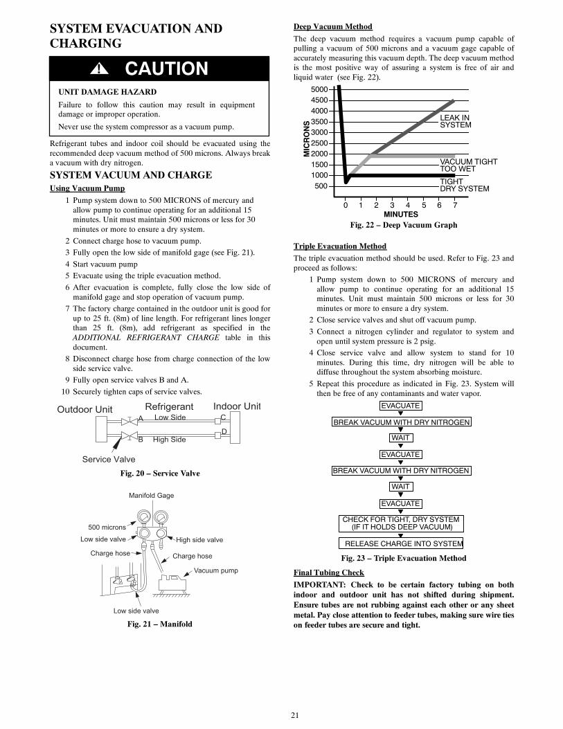
SYSTEM EVACUATION ANDCHARGING
UNIT DAMAGE HAZARD
Failure to follow this caution may result in equipmentdamage or improper operation.
Never use the system compressor as a vacuum pump.
CAUTION!
Refrigerant tubes and indoor coil should be evacuated using therecommended deep vacuum method of 500 microns. Always breaka vacuum with dry nitrogen.
SYSTEM VACUUM AND CHARGEUsing Vacuum Pump
1 Pump system down to 500 MICRONS of mercury andallow pump to continue operating for an additional 15minutes. Unit must maintain 500 microns or less for 30minutes or more to ensure a dry system.
2 Connect charge hose to vacuum pump.
3 Fully open the low side of manifold gage (see Fig. 21).
4 Start vacuum pump
5 Evacuate using the triple evacuation method.
6 After evacuation is complete, fully close the low side ofmanifold gage and stop operation of vacuum pump.
7 The factory charge contained in the outdoor unit is good forup to 25 ft. (8m) of line length. For refrigerant lines longerthan 25 ft. (8m), add refrigerant as specified in theADDITIONAL REFRIGERANT CHARGE table in thisdocument.
8 Disconnect charge hose from charge connection of the lowside service valve.
9 Fully open service valves B and A.
10 Securely tighten caps of service valves.
Outdoor Unit Indoor UnitRefrigerant
Service Valve
Low Side
High Side
A
B
C
D
Fig. 20 – Service Valve
Manifold Gage
500 microns
Low side valve High side valve
Charge hose Charge hose
Vacuum pump
Low side valve
Fig. 21 – Manifold
Deep Vacuum Method
The deep vacuum method requires a vacuum pump capable ofpulling a vacuum of 500 microns and a vacuum gage capable ofaccurately measuring this vacuum depth. The deep vacuum methodis the most positive way of assuring a system is free of air andliquid water (see Fig. 22).
500
MINUTES0 1 2 3 4 5 6 7
10001500
LEAK INSYSTEM
VACUUM TIGHTTOO WET
TIGHTDRY SYSTEM
2000MICRONS
250030003500400045005000
Fig. 22 – Deep Vacuum Graph
Triple Evacuation Method
The triple evacuation method should be used. Refer to Fig. 23 andproceed as follows:
1 Pump system down to 500 MICRONS of mercury andallow pump to continue operating for an additional 15minutes. Unit must maintain 500 microns or less for 30minutes or more to ensure a dry system.
2 Close service valves and shut off vacuum pump.
3 Connect a nitrogen cylinder and regulator to system andopen until system pressure is 2 psig.
4 Close service valve and allow system to stand for 10minutes. During this time, dry nitrogen will be able todiffuse throughout the system absorbing moisture.
5 Repeat this procedure as indicated in Fig. 23. System willthen be free of any contaminants and water vapor.
CHECK FOR TIGHT, DRY SYSTEM(IF IT HOLDS DEEP VACUUM)
EVACUATE
BREAK VACUUM WITH DRY NITROGEN
WAIT
EVACUATE
RELEASE CHARGE INTO SYSTEM
BREAK VACUUM WITH DRY NITROGEN
EVACUATE
WAIT
Fig. 23 – Triple Evacuation Method
Final Tubing Check
IMPORTANT: Check to be certain factory tubing on bothindoor and outdoor unit has not shifted during shipment.Ensure tubes are not rubbing against each other or any sheetmetal. Pay close attention to feeder tubes, making sure wire tieson feeder tubes are secure and tight.

22
MAIN LOGICControl Function of Outdoor UnitCooling Mode
1 Cooling conditions and process: If the compressor is in stopstatus and you start the unit for cooling operation, when one ofthe indoor units reaches the cooling set point, the unit startscooling operation; in this case, the electronic expansion valve,the outdoor fan and the compressor start operation.
2 Stop in cooling operationa. Compressor stops -- The compressor stops gradually, theoutdoor fan stops after 1 min.
b. Some of the indoor units reach the stop condition (thecompressor does not stop). The compressor operatesaccording to the required frequency. For the indoor unitwithno requirement, the corresponding electronic expansionvalve is closed to 0P.
3 Cooling mode transfers to heating mode: When the unittransfers to heating mode, the 4--way valve is energizedafter the compressor runs for 40s.
4 4--way valve: In this mode, the 4--way valve is closed.5 Outdoor fan control in cooling mode: The outdoor fan startsbefore 5s of the starting of compressor. The outdoor fan runsin high speed for 40s after starting and then it will run in setspeed. The fan will run at every speed for at least 80s. (Whenthe quantity of indoor unit changes, the control part adjusts theoutdoor fan according to the quantity of indoor units andoutdoor temperature.); when the compressor stops, the outdoorfan runs at present speed and stops after 1 min.
Dry Mode
1 The dry conditions and process are the same as those incooling mode;
2 The status of 4--way valve: closed;
3 The temperature setting range: 60 -- 86°F;
4 Protection function: the same as those in cooling mode;
5 In Dry mode, the maximum value A of the capacityrequirement percentage of single unit is 90% of that inCooling mode. The open condition of the electronicexpansion valve, outdoor fan and compressor is the same asthose in cooling mode.
Heating Mode
1 Heating conditions and process: When one of the indoorunits reaches the heating operation condition, the unit startsheating operation.
2 Stop in heating operation:a. When all the indoor units reach the stop condition, thecompressor stops and the outdoor fan stops after 1 min;
b. Some of the indoor units reach the stop condition. Thecompressor reduces the frequency immediately and operatesaccording to the required frequency;
c. Heating mode transfers to cooling mode (dry mode), fanmode:
— The compressor stops;
— The outdoor fan stops after 1min;
— The status of 4--way valve: energized;
3 Outdoor fan control in heating mode: The outdoor fan starts5s before the compressor and will run in high speed for 40s;The fan will run at every speed for at least 80s; When thecompressor stops, the outdoor fan stops after 1min.
4 Defrosting function: When the defrosting condition is met,the frequency of the compressor starts to decrease and waitsfor defrosting. The outdoor fan stops after the 4--way valvecloses, meanwhile the 4--way valve reverses the direction;after the 4--way valve reverses the direction.The compressor frequency starts to rise and then begins tocalculate the time of defrosting, the frequency of thecompressor rises to reach the defrosting frequency.
5 Oil--returned control in heating modea. Oil--returned condition: The whole unit is operating in lowfrequency for a long time
b. Oil--returned process in heating mode: The indoor unitdisplays “H1”.
c. Oil--returned finished condition in heating mode: Theduration reaches 5min.
Fan Mode
The compressor, the outdoor fan and the 4--way valve are closed;temperature setting range is 60 -- 86°F.
Protection FunctionMode Conflict Protection of Indoor Unit
When the setting mode is different between the indoor units, theunit runs in below status:
1 The mode of the first operating indoor unit is the prioritymode, when compare the mode of the other indoor units tosee if there is a conflict. Cooling mode (dry mode) is inconflict with heating mode.
2 Fan mode is in conflict with heating mode and the heatingmode is the priority mode. No matter which indoor unitoperates first, the unit will run in heating mode.
Overload Protection Function
When the tube temperature is too low, the compressor raises theoperation frequency; when the tube temperature is too high, thecompressor frequency is restricted or lows down the operationfrequency; when the tube temperature is too high, the compressorprotection stops running. If the discharge temperature protectioncontinuously appears for 6 times, the compressor can resume runningafter cutting off the power and restarting the power. (If the runningtime of the compressor is longer than 7min, the protection timesrecord will be cleared).
Discharge Protection Function
When the discharge temperature is low, the compressor raises theoperation frequency; when the discharge temperature is high, thecompressor frequency is restricted when the discharge temperatureis too high, the compressor protection stops running. If thedischarge temperature protections continuously appears for 6 times,the compressor can not resume running. The compressor canresume running after cutting off the power and then puttingthrough the power. (If the running time of the compressor is longerthan 7min, the protection times record will be cleared).
Communication Malfunction
Detection of the quantity of installed indoor units and BranchBox: After 3min of energizing, if the outdoor unit does not receivethe communication data of certain indoor unit, the outdoor unitwill judge that indoor unit is not installed and will treat it as it isnot installed. If the outdoor unit receives the communication dataof that indoor unit later, the outdoor unit will treat that unit as it isinstalled.

23
Compressor high--pressure protection
1 When the high--pressure switch is detected cut off for 3scontinuously, the compressor will enter high--pressureprotection as it stops when reaching set temperature.Meanwhile, the outdoor unit will send the signal of“high--pressure protection” to the indoor units;
2 After the issue is fixed, the compressor can resume runningonly after performing a power cycle.
3 High pressure protection activates at 638 PSI and allows thesystem to run again at 464 PSI.
Compressor low--pressure protection
1 1) Low Pressure Protection for Shutdown
a. After the compressor stops for five minutes, if it is detectedthat the low pressure protection is active, then a low pressureprotection signal will be send out.
b. If it is detected continuously for three seconds that the lowpressure protection is active after the compressor stops forless than five minutes, then a low pressure protection signalwill be send out. However, if the low pressure protectionoccurs twice in one hour, then it becomes unrecoverable andhas to be recovered by powering the outdoor unit again.
2 Low Pressure Protection during the Operation
a. When it is detected continuously for three seconds that thelow pressure protection is work, then the whole unit shouldbeshutoff and a low pressureprotection signal should besentto the indoor unit.
b. On condition that a low pressure protection error occurs andthe whole unit has stopped for more than three minutes andit is detected continuously for six seconds that the lowpressure protection switch is closed, then this error can beeliminated. However, if the low pressure protection occurstwice in one hour, then it has to eliminate the error bypowering the outdoor unit again.
c. Low pressure protection activates at 20 PSI and allows thesystem to run again at 44 PSI.
Compressor overload protection
If the compressor overload switch is detected, the indoor unit displaysthe corresponding malfunction as it stops when the indoor temperaturereaching set temperature. When the compressor stops for more than3min and the compressor overload switch is reset, the unit will resumeoperation status automatically. If the protection appears for more than6 times (if the running time of the compressor is longer than 30min,the protection times record will be cleared), the unit can not resumeoperation status automatically, but can resume running only aftercutting off the power and then putting through the power.
Control Function of Indoor UnitRunning Mode
1 COOL 2.DRY 3.HEAT 4.AUTO 5 FAN
Basic Functions of the System
1 COOL Mode: Under this mode, the fan and swing functiongoes as the set conditions, and the set temperature range is60 -- 86°F.
2 DRY Mode: Under this mode, the fan runs at the low speedand the Swing function is performed under the setconditions. The set temperature range is 60--86°F.
3 FAN Mode: Under this mode, only the fan of the indoorunit runs. And if the auto speed is set, the fan runs under thesame condition as the COOL mode.
4 HEAT Mode:
a. Under this mode, the set temperature range is 60--86°F.
b. The defrosting symbol “H1” appears when the defrostingsignal is received from the outdoor unit.
5 AUTO Mode
a. When the ambient temperature is higher than 7 °F, the unitwill run in the Cool Mode.
b. For the cooling and heating unit, if the ambient temperatureis or lower than 71 °F, the unit will run in the HEAT mode.
c. When the indoor ambient temperature is higher than 71 °Fhowever lower than 78 °F, the unit starts to work under theAUTO or DRY mode and shifts to the FANmode, while theunit which starts to work under the other mode keeps thecurrent running mode.
Other Control
1 Beeper Control: When the controller is powered on or itreceives a valid either press button signal or remote controlsignal, the beeper will utter a warning tone.
2 Auto Speed Control:
a. Under the HEAT mode:
S If the ambient temperature is equal or higher than the settemperature, the fan runs at the low speed;
S If the ambient temperature minus 37 °F is equal or lowerthan the set temperature, the fan runs at the mediumspeed.
S If the ambient temperature minus 37 °F is lower than theset temperature minus 37 °F the fan runs at the highspeed.
b. Under the COOL mode:
S If the ambient temperature is equal to or lower than theset temperature, the fan runs at the low speed.
S If the ambient temperature is between the set temperatureand the set temperature minus 37 °F, the fan runs at themedium speed.
S If the ambient temperature is higher than the settemperature plus 37 °F, the fan runs at the high speed.
c. Under the FAN mode:
S The fan runs at the medium speed constantly
S Once the fan starts, its speed cannot be changed until ithas run for at least 30 seconds at the currently set speed.
S When the ambient temperature is lower than the settemperature, the indoor unit runs at the high speed.
S When the ambient temperature is higher than the setspeed however lower than the set temperature plus 4°F,the indoor fan runs at the medium speed.
S When the ambient temperature is lower than the settemperature plus 4°F, the fan runs at the low speed.
d. Under the Cool and Fan Modes:
S When the ambient temperature is higher than the settemperature plus 6°F, the indoor unit runs at high speed.
S When the ambient temperature is higher than the settemperature plus 2°F, however lower than the settemperature plus 6°F, the indoor unit fan runs at themedium speed.
S When the ambient temperature is lower that the settemperature plus 2°F, the fan runs at the low speed.
e. Once the fan starts at a certain speed, it keeps running at thisspeed for no less than 30 seconds prior to any changeoverstated above.
3 AUTO Press Button: The unit runs under the AUTO modeby pressing this button when the unit is on. In this state, thefan of the indoor unit runs at the auto speed with the swingfunction activated. When the unit is on, it will be turned offby pressing this button.
NOTE: This button is unavailable on the floor/ceiling unit.

24
4 Sleep: Under this mode, the proper sleep curve is adopted inaccordance with different set temperatures. Under theCOOL mode or the DRY mode, the temperature increasesby 2°F after one hour and by another 2°F after anotherhour, after that, the temperature will be kept on. Under theHEAT mode, the temperature decreases by 2°F after onehour and by another 2°F after another hour. After that thetemperature will remain.
5 Timer:
a. TimerOn:When the unit is powered on however in the idlestate, it is available to setwhen the a user starts the unit.Whenthe unit starts, it runs as in the previously set mode. The setrange of the timer is 0.5~24 hours with a interval of 0.5 hour.
b. Timer Off: When the unit is on, a user can set when to stopthe unit. The set range of the time is 0.5~24 hours with ainterval of 0.5 hour.
6 Memory
a. Memorizing Objects: modes (AUTO, COOL, DRY, FAN,HEAT), swing, set temperature, set fan speed, etc.
b. When the indoor unit works without the wired controller, itresumes the working condition as the power failure occursafter it is powered on again.When the indoor unit is with thewired controller, it is available to set thememory function bypressing the corresponding buttons of the wired controller.
c. When the indoor unit works without the wired controller, ifthe timer is not set for the last remote control instruction, thesystem memorizes this last instruction and works followingit; if the timer is set, it will be canceled as the power failureoccurs and will have to be reset.
d. When the indoor unit works with the wired controller, itworks as the message sent by the wired controller after it ispowered on again.
7 Selection of the Indoor Temperature Sensor
a. For the duct type indoor unit: Under the COOL, HEAT, DRY,orFANmode, the return air temperature sensor is adopted;whileunder the HEAT mode, it is the receiver temperature sensor.For the cassette type, floor ceiling type indoor unit: Under allmodes, the return air temperature sensor is adopted.
b. When the duct type, cassette type, or the floor ceiling typeindoor unit works with the wired controller, the ambienttemperature sensor can be set in the following four ways:
S 01: The indoor temperature sensor is set for the return air.
S 02: The indoor temperature sensor is set for the wiredcontroller.
S 03: The indoor temperature sensor is set for the wiredcontroller under the HEAT mode, and for the return airunder any other mode.
S 04: The indoor temperature sensor is set for the return airunder the HEAT mode, and for the wired controllerunder any other mode
c. Setting of the Ambient Temperature Sensor of the WiredController.
S When the unit is off, it is available to go to thedebugging status by pressing the “Function” and“Timer” buttons for five seconds, and the correspondingcode appears on the temperature area of the wiredcontroller. There are four kinds of codes which can beadjusted through theB/Y button.
S The 03 is the default code. The setting of the ambienttemperature sensor of the wired controller should bememorized.
S Press the Enter/ Cancel button to confirm and exit thesetting. If there is no response to the last button press within20 seconds, the system exits the setting and enters thenormal “Off” status however with the setting still saved.
8 Switchover of the Defrosting Mode: On condition that theunit is off, if “H1” does not appear on the wireless controller,then the unit enters the setting status of the “Defrosting Mode1” as it is turned on through the wired controller. Once theindoor unit receives this signal, it sends it to the outdoor unit.In contract, if “H1” is displayed, the unit enters the settingstatus of the “Defrosting Mode 2”, and the indoor unit alsosends this signal to the outdoor unit as soon as it receives it.On condition that the unit is off, it is available to switch overthe “Defrosting Mode 1” and “Defrosting Mode 2” bypressing the “MODE” and “BLOW” buttons simultaneously.
9 Turbo: As soon as the controller receives the “Turbo”instruction, the indoor unit fan runs at the high speed.
10 Blow Function: This function automatically blows awaymoisture inside the indoor unit exchanger to prevent moldfrom growing after the unit is shut off.
a. On condition that this function is activated, when the“On/Off” press button is operated, the fan of the indoor unitstill runs for ten minutes (with the symbol “BLOW”displayed). At this time, the fan will stop as this function isdeactivated.
b. This function is unavailable under the AUTO, FAN, andHEAT modes.
I FEEL
1 If the indoor PCB receives the signal which results frompressing the I FEEL button on the remote controller, thebuzzer emits a sound and this indicates the I FEEL function isinitiated. However when the indoor PCB receives a signalwhich was sent from the remote controller every 3 minutes, thebuzzer will not respond. When the unit is running with the IFEEL function, the PCB controls the unit according to thetemperature from I FEEL signal, and the temperature collectionfunction of room temperature sensor will be shielded, howeverthe error detective function of room temperature sensor will bestill valid.
2 When the I FEEL function is available, the PCB controls theunit according to the room temperature from the remotecontroller and the setting temperature.
3 The PCB take actions to the mode change information fromremote controller signal, however it will not affected by thesetting temperature.
4 When the unit is running with I FEEL function, if the PCBdoes not receive any signal from remote controller for 7minutes or pressing I FEEL button again, the I FEEL functionwill be turned off automatically, and the temperature controlsthe unit according to the room temperature detected from itsown room temperature sensor and setting temperature.
Louver Position Memory Function (High Wall, Floor Console)
When starting the unit again after shutting down, its louver returnsto the angle originally set by the user, however the precondition isthat the angle must be within the allowable range, if it exceeds, itwill memorize the maximum angle of the louver. During operation,if the power fails the louver will return to the default angle.

25
46_F (8_C) Heating (heating setback) (All Indoor Units)
In heating operation, the preset temperature of the air conditionercan be as low as 46_F, which keeps the room temperature steady at46_F and prevents household pipes from freezing when the houseis unoccupied for a long time in severe cold weather.
Silence Operation (High Wall, Cassette, Floor Console)
Press the “silence” button on remote controller to initiateSILENCE function. When the silent function is active , the fanspeed will run below its rated ” low” fan speed on the remote andsupply a faint breeze to the occupied space, which reduces noiseand creates a comfortable environment.
TROUBLESHOOTINGThis section provides the required flow charts to troubleshootproblems that may arise.
NOTE: Information required in the diagnoses can be foundeither on the wiring diagrams or in the appendix.
Required Tools:
The following tools are needed when diagnosing the units:S Digital multimeterS Screw drivers (Phillips and straight head)S Needle--nose pliersS Refigeration gauges
Recommended Steps
1 Refer to the diagnostic hierarchy charts below anddetermine the problem at hand.
2 Go to the chart listed in the diagnostic hierarchy and followthe steps in the chart for the selected problem.
For the ease of service, the systems are equipped with diagnosticcode display LED’s on both the indoor and outdoor units. Theoutdoor diagnostic display is on the outdoor unit board and islimited to very few errors. The indoor diagnostic display is acombination of flashing LED’s on the display panel on the front ofthe unit. If possible always check the diagnostic codes displayed onthe indoor unit first.
The diagnostic codes for the indoor and outdoor units are listed inthe appendix.
Problems may occur that are not covered by a diagnostic code,however are covered by the diagnostic flow charts. These problemswill be typical air conditioning mechanical or electrical issues thatcan be corrected using standard air conditioning repair techniques.
For problems requiring measurements at the control boards, notethe following:
1 Always disconnect the main power.
2 When possible check the outdoor board first.
3 Start by removing the outdoor unit top cover.
4 Reconnect the main power
5 Probe the outdoor board inputs and outputs with a digitalmulti--meter referring to the wiring diagrams.
6 Connect the red probe to hot signal and the black probe tothe ground or negative.
7 Note that some of the DC voltage signals are pulsatingvoltages for signal. this pulse should be rapidly moving atall times when there is a signal present.
8 If it is necessary to check the indoor unit board you muststart by disconnecting the main power.
9 Next remove the front cover of the unit and then controlbox cover.
10 Carefully remove the indoor board from the control box,place it face up on a plastic surface (not metal).
11 Reconnect the main power and repeat steps 5,6, and 7.
12 Disconnect main power before reinstalling board to avoidshock hazard and board damage.

26
TROUBLESHOOTING (CONT)This unit has on--board diagnostics. Error codes are displayed on the wired remote controller and the outdoor unit microprocessor board withcolored LED lights. The table below explains the error codes on both.
SIZES 18 & 24Table 30—Malfunction Status
Malfunction name Malfunction type Indoordisplay
Zero cross detection circuit malfunction(for indoor unit) Hardware malfunction U8Malfunction protection of jumper cap(for indoor unit) Hardware malfunction C5
Feedback of without I DU motor(for indoor unit) Hardware malfunction H6Indoor ambient temperature sensor is open/short circuited Hardware malfunction F1
Indoor evaporator temperature sensor is open/short circuited Hardware malfunction F2Liquid valve temperature sensor is open/short circuited Hardware malfunction b5
Gas valve temperature sensor is open/short circuited Hardware malfunction b7Modular temperature sensor is open/short circuited Hardware malfunction P7
Outdoor ambient temperature sensor is open/short circuited Hardware malfunction F3Outdoor condenser middle pipe temperature sensor is open/short circuited Hardware malfunction F4
Outdoor discharge temperature sensor is open/short circuited Hardware malfunction F5Communication malfunction Hardware malfunction E6
Malfunction of phase current detection circuit for compressor Hardware malfunction U1
Module high temperature protection Viewing malfunction code through remote controller within 200s;displayed directly on the indoor display after 200s
P8Refrigerant lacking or blockage protection of system (not available for
residential ODU)F0
Charging malfunction of capacitor Hardware malfunction PUHigh pressure protection of system Hardware malfunction E 1
Low pressure protection of system (reserved) Hardware malfunction E3
Compressor overload protection Viewing malfunction code through remote controller within 200s;displayed directly on the indoor display after 200s
H3
Indoor unit and outdoor unit do not match Hardware malfunction LPMalfunction of memory chip Hardware malfunction E E
Wrong connection of communication wire or malfunction ofelectronic expansion valve
Hardware malfunction dn
Malfunction protection of outdoor fan 1 Hardware malfunction L3Detection status of wrong connection of communication wire or
malfunction of electronic expansion valveOperation status dd
Mode conflict Operation status E7Refrigerant recycling mode Operation status Fo
X-fan Operation status ALDefrosting or oil return i n heating mode Operation status H 1
Start failure of compressor
Viewing malfunction code through remote controller within 200s;displayed directly on the indoor display after 200s
LcHigh discharge temperature protection of compressor E4
Overload protection E8Whole unit over-current protection E5
Compressor phase current protection P5Compressor de-synchronizing H7
Compressor phase-lacking/phase-inverse protection LdIPM modular protection H5
DC bus-bar low voltage protection PLDC bus-bar high voltage protection PH
PFC protection HCThe four-way valve is abnormal U7

27
TROUBLESHOOTING (CONT)This unit has on--board diagnostics. Error codes are displayed on the wired remote controller and the outdoor unit microprocessor board withcolored LED lights. The table below explains the error codes on both.
SIZES 30, 36 & 42Table 31—Malfunction Status
Name of malfunctionThe indicator display
Indoor displayYellow light Red light Green light
Compressor runs Flash once
Defrost Flash twice H1
Anti-freezing protection Flash 3 times E2
IPM protection Flash 4 times H5
AC over-current protection Flash 5 times E5
Over-burden protection Flash 6 times H4
Compressor exhaust high temperature protection Flash 7 times E4
Compressor overload protection Flash 8 times H3
Power protection Flash 9 times L9
EEPROM reads and write protection Flash 11 times
Low PN voltage protection Flash 12 times PL
Over voltage protection for PN Flash 13 times PH
PFC protection Flash 14 times HC
PFC module temperature protection Flash 15 times oE
Low pressure protection Flash 17 times E3
High pressure protection Flash 18 times E1
Limit/decline frequency(electric current) Flash 1 times
Frequency limit exhaust) Flash 2 times
Frequency limit(Over-burden) Flash 3 times
Outdoor ambient sensor malfunction Flash 6 times F3
Outdoor tube sensor malfunction Flash 5 times F4
Exhaust sensor malfunction Flash 7 times F5
Attain the temperature of switch on Flash 8 times
Frequency limit(power) Flash 13 times
Outdoor fan malfunction Flash 14 times
Frequency limit(PFC module temperature) Flash 15 times
PFC module sensor malfunction Flash 16 times oE
Liquid pipe temperature sensor malfunction of A Flash 17 times
Gas pipe temperature sensor malfunction of A Flash 18 times
Liquid pipe temperature sensor malfunction of B Flash 19 times
Gas pipe temperature sensor malfunction of B Flash 20 times
Liquid pipe temperature sensor malfunction of C Flash 21 times
Gas pipe temperature sensor malfunction of C Flash 22 times
Liquid pipe temperature sensor malfunction of D Flash 23 times
Gas pipe temperature sensor malfunction of D Flash 24 times
Liquid pipe temperature sensor malfunction of E Flash 25 times
Gas pipe temperature
sensor malfunction of E Flash 26 times
Exit of the condenser tube sensor malfunction Flash 27 times
Correspondence is normal Flash 7 times (n =indoor unit number)
Communication failure between indoor unit and outdoor unit Often bright(indoor unit all Communication failure)
Indoor ambient sensor malfunction F1
Indoor evaporate sensor malfunction F2
Mode conflict E7
Accept fluorine mode Fo
Jumper cap malfunction protection C5

28
TROUBLESHOOTING (CONT)This unit has on--board diagnostics. Error codes are displayed on the wired remote controller and the outdoor unit microprocessor board withcolored LED lights. The table below explains the error codes on both.
SIZES 48 -- 56Table 32—Malfunction Status
Errors of DefinitionMain control display for outdoor unit Indoor unit
codeTesting Board
CodeYellow LED Red LED Green LEDThe compressor is start up Flash 1 time
IPM current protection Flash 3 times H5 H5
IPM temperature protection Flash 5 times P8 P8
PFC current protection Flash 7 times HC HC
PFC temperature protection Flash 8 times P8 P8
Low voltage protection Flash 9 times PL PL
High voltage protection Flash 10 times PH PH
Low pressure protection Flash 11 times E3 E3
High pressure protection Flash 12 times E8 E8
High pressure switch protection Flash 13 times E1 E1
Capacitor charging error Flash 14 times PU PU
Current protection Flash 15 times E5 E5
Memory card error Flash 16 times EE EE
Compressor demagnetizing protection Flash 17 times HE HE
Compressor de-synchronizing Flash 18 times H7 H7
Compressor phase lack Flash 19 times U2 U2
Compressor phase circuit detection error Flash 20 times U1 U1
Compressor current protection Flash 21 times L9 L9
Compressor overload protection Flash 22 times H3 H3
Compressor discharge temperature protection Flash 23 times E4 E4
Lack of refrigerant or jam protection Flash 31 times F0 F0
Normal operation Flash 1 time
Frequency limitation for current protection Flash 2 times F8
Oil returning mode Flash 3 times F7 F7
Defrosting mode Flash 4 times H1 H1
Frequency limitation for IPM temperature protection Flash 5 times EU EU
Frequency limitation for PFC temperature protection Flash 6 times EU EU
Frequency limitation for compressor overload protection Flash 8 times LU
Frequency limitation for discharge temp. protection Flash 9 times F9
Frequency limitation for low pressure protection Flash 10 times Pn
Frequency limitation for high pressure protection Flash 11 times F6 F6
Discharge temperature sensor error Flash 12 times F5 F5
Outside temperature sensor error Flash 13 times F3 F3
Suction temperature sensor error Flash 15 times dc
Condenser temperature sensor error Flash 16 times A7 A7
Sub-cool temperature sensor error Flash 17 times bC
Low pressure sensor error Flash 18 times dL
High pressure sensor error Flash 19 times e1
Fan motor protection Flash 20 times H6 H6
Driving board is connected Flash 1 time
Testing board is connected Flash 2 times
Computer is connected Flash 4 times
Indoor unit 1 is connected Flash 5 times
Indoor unit 2 is connected Flash 6 times

29
TROUBLESHOOTING (CONT)This unit has on--board diagnostics. Error codes are displayed on the wired remote controller and the outdoor unit microprocessor board withcolored LED lights. The table below explains the error codes on both.
SIZES 48 -- 56Table 33—Troubleshooting
Errors of definitionMain control display for outdoor unit
Indoor unit code Testing board
codeYellow LED Red LED Green LED
Indoor unit 3 is connected Flash 7 times
Indoor unit 4 is connected Flash 8 times
Indoor unit 5 is connected Flash 9 times
Indoor unit 6 is connected Flash 10 times
Indoor unit 7 is connected Flash 11 times
Indoor unit 8 is connected Flash 12 times
Indoor unit 9 is connected Flash 13 times
Indoor anti-freeze protection E2 E2
Inside temperature sensor error F1 F1
Evaporator midway temp sensor error F2 F2
Liquid pipe of Branch Box temperature sensor error b5 b5
Gas pipe of Branch Box temperature sensor error b7 b7
Mode conflicts E7 E7
Communication error BU 1 Indoor unit A
Indoor unit B
Indoor unit C
BU 2 Indoor unit A
Indoor unit B
Indoor unit C
BU 3 Indoor unit A
Indoor unit B
Indoor unit C
Communication error between the main board and driving board P6
Communication error between the main board and testing board CE
Indoor unit gas sensor error Fn
Indoor unit humidity sensor error L1
Indoor unit water full protection E9
Jumper terminal error C5 C5
Power supply phase lack dJ
Outdoor unit fan motor error L3
Refrigerant recovery mode Fo Fo
30
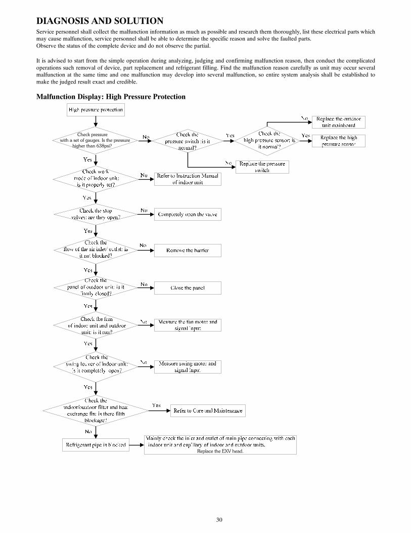
DIAGNOSIS AND SOLUTIONService personnel shall collect the malfunction information as much as possible and research them thoroughly, list these electrical parts whichmay cause malfunction, service personnel shall be able to determine the specific reason and solve the faulted parts.Observe the status of the complete device and do not observe the partial.
It is advised to start from the simple operation during analyzing, judging and confirming malfunction reason, then conduct the complicatedoperations such removal of device, part replacement and refrigerant filling. Find the malfunction reason carefully as unit may occur severalmalfunction at the same time and one malfunction may develop into several malfunction, so entire system analysis shall be established tomake the judged result exact and credible.
Malfunction Display: High Pressure Protection
Replace the EXV head.
Check pressure with a set of gauges. Is the pressure
higher than 638psi?

31
Malfunction Display: Low Pressure Protection
Low pressure protection
Check the low pressure with a set of gauges:
is it lower than 20PSI?
Check work mode of indoor unit:
is it properly set?
Check stopvalves: are they completely
open?
Check the panel of outdoor unit: is it
firmly closed?
Check theflow of the air inlet/outlet: is
it not blocked?
Check thefans of indoor unit and outdoor
unit: is it run?
Check theswing louver of indoor unit:
is it completely open?
Check theindoor/outdoor filter and heat
exchange fin: is there filth blockage?
Refrigerant pipe is blocked
Refer to Care and Maintenance
Measure swing motor and signal input
Measure the fan motor and signal input
Remove the barrier
Close the panel
Completely open the valve
Refer to Instruction Manual of indoor unit
Yes
No
Check refrigerant in the system: is it
sufficient?
Check the inlet and outlet of main pipe connecting with each indoor unit and capillary of indoor and outdoor
units. Replace the parts like filter, capillary and so on
Charge refrigerant according to the amount specified in the nameplate and calculated additional amount
Replace the outdoor unit mainboard
Check thelow pressure sensor: is
it normal?Replace the low pressure sensor
Yes
Yes
Yes
Yes
Yes
Yes
Yes
Yes
Yes
No
No
No
No
No
No
No
No
No

32
Malfunction Display: Discharge Temperature ProtectionDischarge temperature protection
Measure the discharge temperature: does it have
reached 257 ?
Check and repair the leakage of the unit. Charge refrigerant according to the required volume
Replace the oudoor unit mainboard
Measure resistance value of discharge
temperature sensor: is it correct(50K )?
Replace relevant discharge temperature sensor
Are the electronic expansion valves
broken?
When the discharge temperature is higher than
230 , whether the compressor reduces its capacity?
Check thecapacity demand of indoor units:
is it in the range of outdoor unit capacty ?
Yes
Replace relevant electronic expansion valve
Replace the oudoor unit mainboard
Refer to the dial-up of indoor and outdoor unit
No
Yes
Yes
Yes
Yes
No
No
No
No
Malfunction Display: Over Current Protection
Over current protection
Check the wiring of the compressor: is it
properly connected?
Is the currentvalue higher than the preset
value of protector?
Is the high pressure normal?
Is the voltage normal?
Replace the mainboard
Correct the compressor wiring
Replace the overcurrent protector
Refer to high voltage protection
Contact the power supply company
Yes
No
Yes
Yes
Yes
No
No
No
33
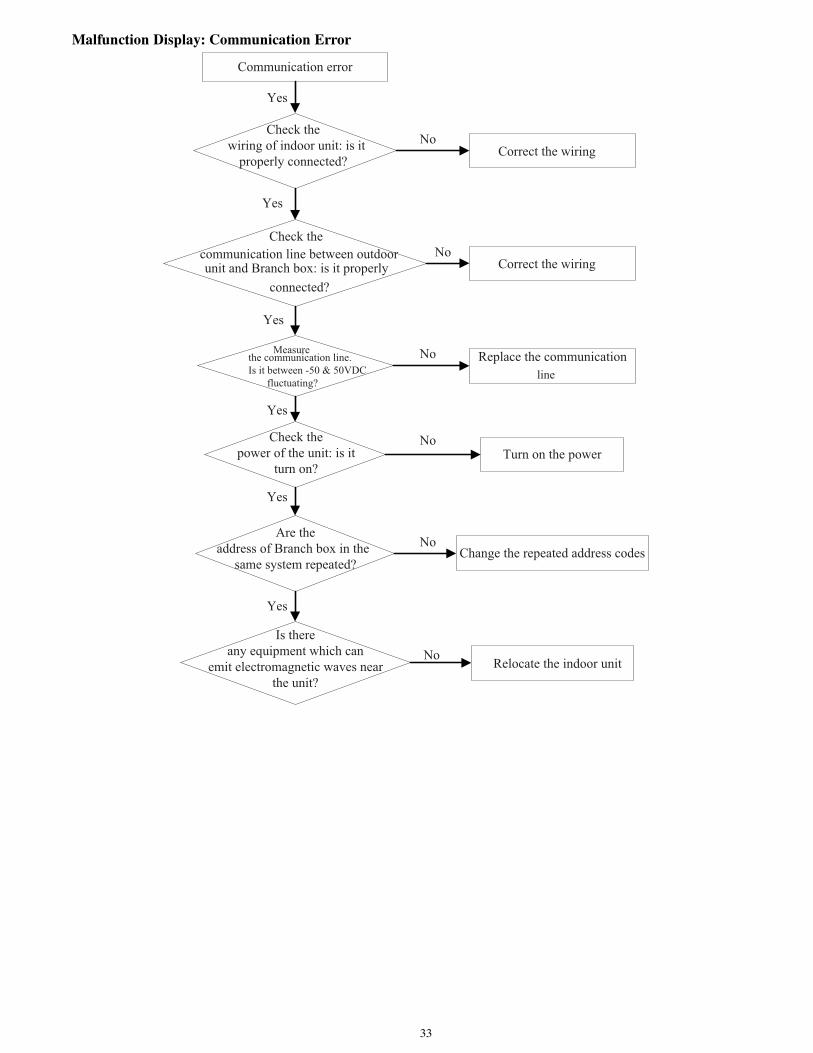
Malfunction Display: Communication Error
Communication error
Check the wiring of indoor unit: is it
properly connected?
Measurethe communication line.Is it between -50 & 50VDC fluctuating?
Check the communication line between outdoorunit and Branch box: is it properly
connected?
Check thepower of the unit: is it
turn on?
Correct the wiring
Replace the communication
Turn on the power
Yes
No
Are theaddress of Branch box in the
same system repeated?
Yes
Correct the wiring
Change the repeated address codes
Is there any equipment which can
emit electromagnetic waves near the unit?
Relocate the indoor unit
Yes
Yes
Yes
Yes
No
No
No
No
No
line
34
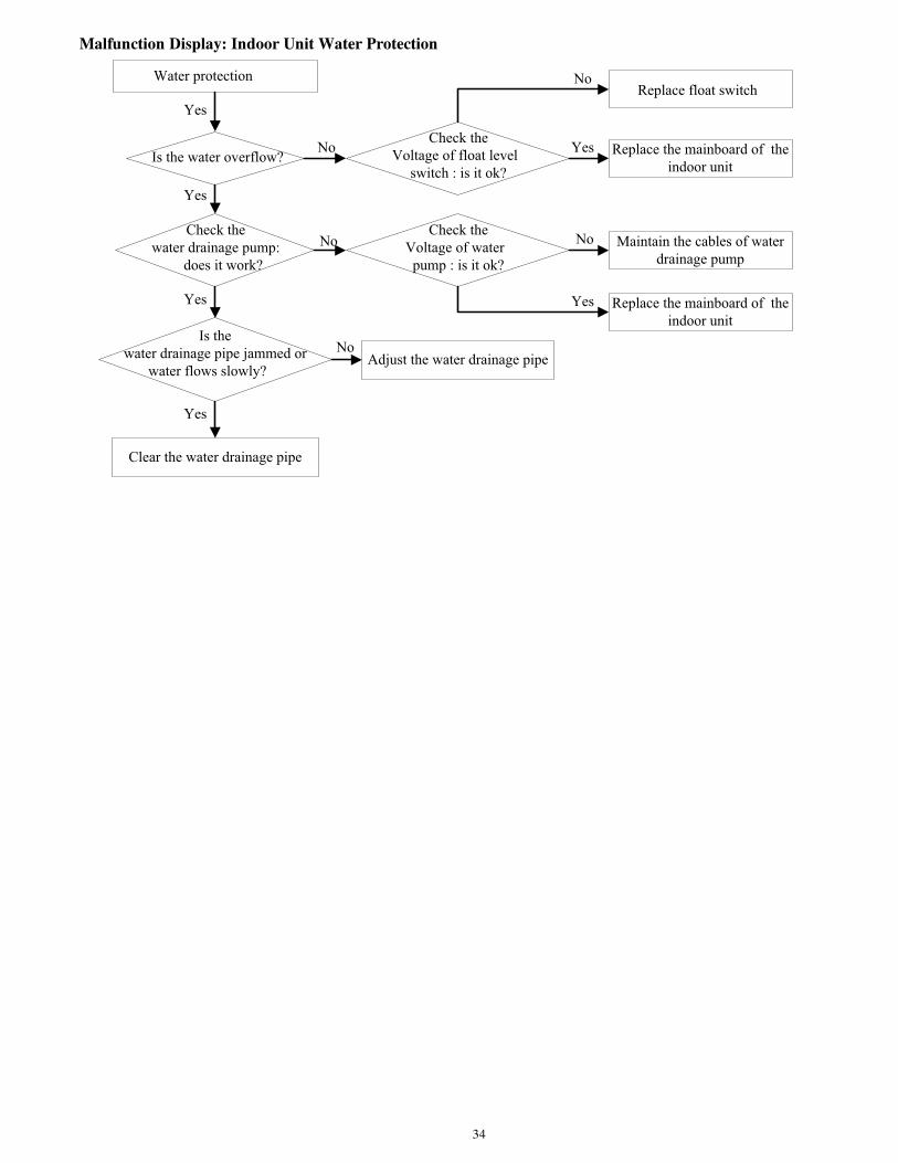
Malfunction Display: Indoor Unit Water Protection
Water protection
Is the water overflow?
Is thewater drainage pipe jammed or
water flows slowly?
Check thewater drainage pump:
does it work?
Replace the mainboard of the indoor unit
Adjust the water drainage pipe
Yes
No
Yes
Maintain the cables of water drainage pump
Clear the water drainage pipe
Yes
Yes
No
No
Check theVoltage of float level
switch : is it ok?
Replace float switch
Check theVoltage of water pump : is it ok?
Replace the mainboard of the indoor unit
Yes
Yes
No
No

35
Malfunction Display: Temperature Sensor ErrorThe resistance value of discharge temperature sensor is 50 KΩ;The resistance value of outside temperature sensor and inside temperature sensor are all 15 KΩ;The others are 20 KΩ.
Temperature sensor error
The plug on temperature sensor is correctly
connected to the socket on mainboard, is it?
Remove the temperature and measure its resistance value: is it within
normal range?
Replace the mainboard of unit
Check the orientation of plug and socket
Replace the temperature sensor
Yes
No
Yes
No
Malfunction Display: High/Low Pressure Sensor Error
Pressure sensor error
The plug on pressure sensor is correctly
connected to the socket on mainboard, is it?
Measure theDC voltage value between black
line and green line of the sensor: is it OK?(0.5~4.5V)
Replace the mainboard of outdoor unit
Check the orientation of plug and socket
Replace the pressuresensor
Yes
No
Yes
No
NOTE: High pressure switch is energized at 638PSI and d--energized at 464PSI Low pressure switch is energized at 20PSI and d--energized at 44PSI.

36
Compressor CheckingMeasure the resistance value of each winding by using the tester.
Fig. 24 – Tester
Terminal Resistance Value
Terminal one Terminal two Terminal three
Blue - Red0.8Ω
(68°F/20°C)
1.77Ω
(68°F/20°C)
0.55Ω
(68°F/20°C)Blue - Black
Red - Blue
Fig. 25 – Compressor Checking
37
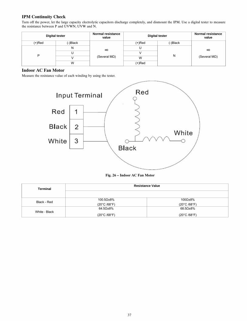
IPM Continuity CheckTurn off the power, let the large capacity electrolytic capacitors discharge completely, and dismount the IPM. Use a digital tester to measurethe resistance between P and UVWN; UVW and N.
Digital testerNormal resistance
value Digital testerNormal resistance
value
(+)Red (-)Black
∞(Several MΩ)
(+)Red (-)Black
∞(Several MΩ)P
N U
NU V
V W
W (+)Red
Indoor AC Fan MotorMeasure the resistance value of each winding by using the tester.
Fig. 26 – Indoor AC Fan Motor
TerminalResistance Value
Black - Red100.5Ω±8%
(20°C /68°F)
100Ω±8%
(20°C /68°F)
White ‐ Black64.5Ω±8%
(20°C /68°F)
68.5Ω±8%
(20°C /68°F)

38
DISSASSEMBLY INSTRUCTIONSHigh Wall UnitRemoval and Assembly of the Fan MotorIMPORTANT: Prior to assembly of the motor, ensure the power supply is cut off.
snoitcurtsnI noitarepO snoitartsullI spetS
1.Remove the front panel, front case and electric box
a) Loosen the screwsb) Unplug the motor
terminals in the electric box. Loosen the earth screws and lift up
2.Remove the evaporator
Unscrew the fixed screws of the evaporator, and then remove it
3.Remove the motor and cross flow fan
a) Unscrew the fixed screws of the motor press plate and cross flow fan
b) Separate the motor from the cross flow fan.

39
DISSASSEMBLY INSTRUCTIONS (CONT)CassetteRemoval and Assembly of the Fan MotorIMPORTANT: Prior to assembly of the motor, ensure the power supply is cut off.
snoitcurtsnI noitarepO snoitartsullI spetS
1.Unscrew the fixed screws of the water tray
Unscrew the fixed screws of the water tray
2.Remove the water tray
Remove the water tray
3.Unscrew the fixed bolts of the fan
Unscrew the fixed bolts of the fan with the spanner
40
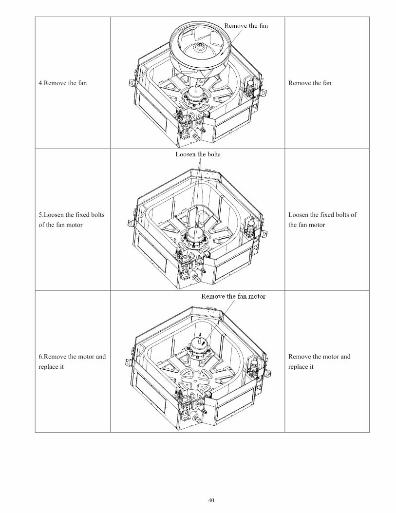
4.Remove the fan
Remove the fan
5.Loosen the fixed bolts of the fan motor
Loosen the fixed bolts of the fan motor
6.Remove the motor and replace it
Remove the motor and replace it

41
7.Screw the fixed bolts of the motor
Screw the fixed bolts of the motor
8.Mount the fan and screw the fixing bolts
Mount the fan and screw the fixing bolts
9.Mount the water tray and screw the screws
Mount the water tray and screw the screws

42
DISSASSEMBLY INSTRUCTIONS (CONT)Removal and Assembly of the Drainage Pump
IMPORTANT: Prior to assembly of the motor, ensure the power supply is cut off.
snoitcurtsnI noitarepO snoitartsullI spetS
1.Unscrew the fixed screws of the water tray
Unscrew the fixed screws of the water tray
2.Remove the water tray
Remove the water tray
3. Pull out the drainage pipe and unscrew the fixed screws the water pump.
Pull out the drainage pipe and unscrew the fixed screws the water pump.
4.Take out the pump and replace it
Take out the pump and replace it

43
5. Connect the drainage pipe and screw the fixed screws the water pump.
Connect the drainage pipe and screw the fixed screws the water pump.
6.Mount the water tray and tighten the screws
Mount the water tray and tighten the screws
44
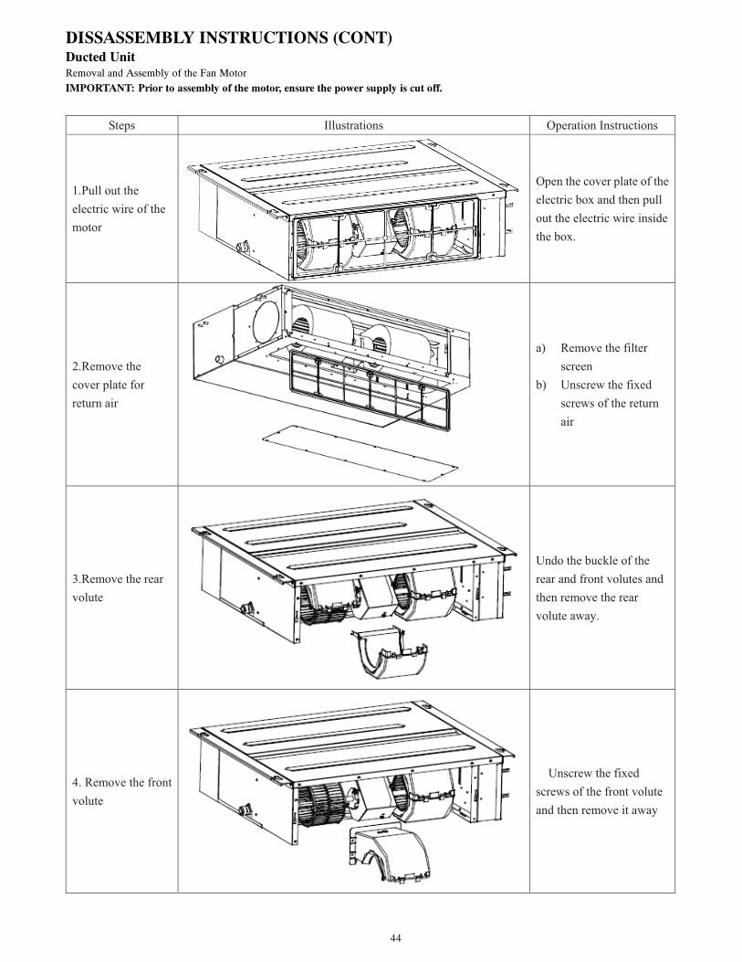
DISSASSEMBLY INSTRUCTIONS (CONT)Ducted UnitRemoval and Assembly of the Fan Motor
IMPORTANT: Prior to assembly of the motor, ensure the power supply is cut off.
snoitcurtsnI noitarepO snoitartsullI spetS
1.Pull out the electric wire of the motor
Open the cover plate of the electric box and then pull out the electric wire inside the box.
2.Remove the cover plate for return air
a) Remove the filter screen
b) Unscrew the fixed screws of the return air
3.Remove the rear volute
Undo the buckle of the rear and front volutes and then remove the rear volute away.
4. Remove the front volute
Unscrew the fixed screws of the front volute and then remove it away

45
5.Loosen the fan blade and fan motor
Unscrew the fixed screws of the fan blades and then undo the buckle of the motor
6. Remove the motor away.
a) Separate the motor away from the motor support.
b) Remove the fan blade
c) Take the motor out from the return air frame
Note: the motor support shall be removed in advance and then changed to the unit.
7.Replace with a new motor
Assemble the fan as the reverse disassembly order and then take a power-on test.
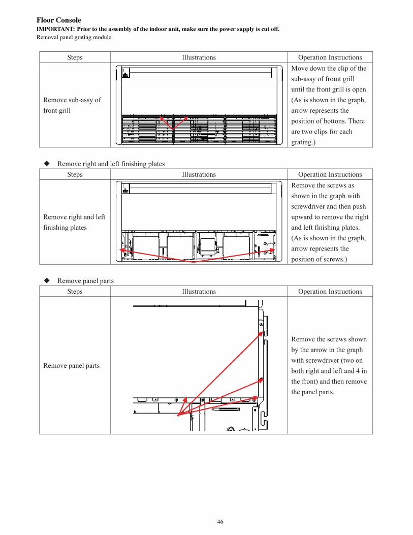
46
Floor ConsoleIMPORTANT: Prior to the assembly of the indoor unit, make sure the power supply is cut off.Removal panel grating module.
snoitcurtsnI noitarepO snoitartsullI spetS
Remove sub-assy of front grill
Move down the clip of the sub-assy of fromt grill until the front grill is open. (As is shown in the graph, arrow represents the position of bottons. There are two clips for each grating.)
Remove right and left finishing plates
snoitcurtsnI noitarepO snoitartsullI spetS
Remove right and left finishing plates
Remove the screws as shown in the graph with screwdriver and then push upward to remove the right and left finishing plates. (As is shown in the graph, arrow represents the position of screws.)
Remove panel parts
snoitcurtsnI noitarepO snoitartsullI spetS
Remove panel parts
Remove the screws shown by the arrow in the graph with screwdriver (two on both right and left and 4 in the front) and then remove the panel parts.
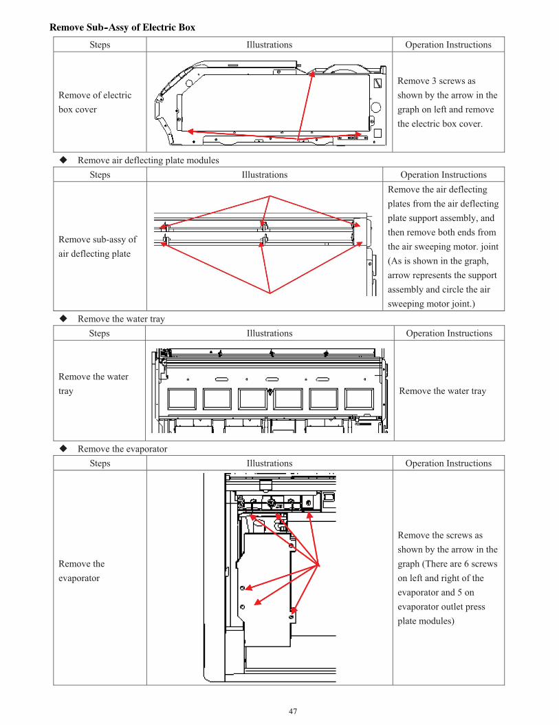
47
Remove Sub--Assy of Electric Box
snoitcurtsnI noitarepO snoitartsullI spetS
Remove of electric box cover
Remove 3 screws as shown by the arrow in the graph on left and remove the electric box cover.
Remove air deflecting plate modules snoitcurtsnI noitarepO snoitartsullI spetS
Remove sub-assy of air deflecting plate
Remove the air deflecting plates from the air deflecting plate support assembly, and then remove both ends from the air sweeping motor. joint (As is shown in the graph, arrow represents the support assembly and circle the air sweeping motor joint.)
Remove the water tray snoitcurtsnI noitarepO snoitartsullI spetS
Remove the water tray
Remove the water tray
Remove the evaporator snoitcurtsnI noitarepO snoitartsullI spetS
Remove the evaporator
Remove the screws as shown by the arrow in the graph (There are 6 screws on left and right of the evaporator and 5 on evaporator outlet press plate modules)

48
snoitcurtsnI noitarepO snoitartsullI spetS
Remove fixing plate sub-assy for air sweeping fans
Remove the screws shown in the graph
Remove fan and motor components snoitcurtsnI noitarepO snoitartsullI spetS
1. Remove front and back scroll cases
Press the buckle at the joints of front and back scroll cases with hands and pull upward to remove the front scroll case. Then remove the screws on the back scroll case. Lift the buckle of back scroll case with hands and remove it.(As is shown in the graph, circle represents 2 screws on left and right.)
2.Remove fans
Remove the fixed screws of fan wheel with inner hexagonal and remove the wheel. The inner hexagonal and its direction of effect are shown by the arrow in the graph.
3. Remove bearing fixing plates
Remove 4 screws on the bearing fixing plates with screwdriver. (As shown in the box in the graph)

49
APPENDIX 1Temperature Sensor Resistance Value Table for T1, T2, T3, T4 (°C--K)
°C °F K Ohm °C °F K Ohm °C °F K Ohm °C °F K Ohm
‐20 -4 115.266 20 68 12.6431 60 140 2.35774 100 212 0.62973
‐19 -2 108.146 21 70 12.0561 61 142 2.27249 101 214 0.61148
‐18 0 101.517 22 72 11.5 62 144 2.19073 102 216 0.59386
‐17 1 96.3423 23 73 10.9731 63 145 2.11241 103 217 0.57683
‐16 3 89.5865 24 75 10.4736 64 147 2.03732 104 219 0.56038
‐15 5 84.219 25 77 10 65 149 1.96532 105 221 0.54448
‐14 7 79.311 26 79 9.55074 66 151 1.89627 106 223 0.52912
‐13 9 74.536 27 81 9.12445 67 153 1.83003 107 225 0.51426
‐12 10 70.1698 28 82 8.71983 68 154 1.76647 108 226 0.49989
‐11 12 66.0898 29 84 8.33566 69 156 1.70547 109 228 0.486
‐10 14 62.2756 30 86 7.97078 70 158 1.64691 110 230 0.47256
-9 16 58.7079 31 88 7.62411 71 160 1.59068 111 232 0.45957
-8 18 56.3694 32 90 7.29464 72 162 1.53668 112 234 0.44699
-7 19 52.2438 33 91 6.98142 73 163 1.48481 113 235 0.43482
-6 21 49.3161 34 93 6.68355 74 165 1.43498 114 237 0.42304
-5 23 46.5725 35 95 6.40021 75 167 1.38703 115 239 0.41164
-4 25 44 36 97 6.13059 76 169 1.34105 116 241 0.4006
-3 27 41.5878 37 99 5.87359 77 171 1.29078 117 243 0.38991
-2 28 39.8239 38 100 5.62961 78 172 1.25423 118 244 0.37956
-1 30 37.1988 39 102 5.39689 79 174 1.2133 119 246 0.36954
0 32 35.2024 40 104 5.17519 80 176 1.17393 120 248 0.35982
1 34 33.3269 41 106 4.96392 81 178 1.13604 121 250 0.35042
2 36 31.5635 42 108 4.76253 82 180 1.09958 122 252 0.3413
3 37 29.9058 43 109 4.5705 83 181 1.06448 123 253 0.33246
4 39 28.3459 44 111 4.38736 84 183 1.03069 124 255 0.3239
5 41 26.8778 45 113 4.21263 85 185 0.99815 125 257 0.31559
6 43 25.4954 46 115 4.04589 86 187 0.96681 126 259 0.30754
7 45 24.1932 47 117 3.88673 87 189 0.93662 127 261 0.29974
8 46 22.5662 48 118 3.73476 88 190 0.90753 128 262 0.29216
9 48 21.8094 49 120 3.58962 89 192 0.8795 129 264 0.28482
10 50 20.7184 50 122 3.45097 90 194 0.85248 130 266 0.2777
11 52 19.6891 51 124 3.31847 91 196 0.82643 131 268 0.27078
12 54 18.7177 52 126 3.19183 92 198 0.80132 132 270 0.26408
13 55 17.8005 53 127 3.07075 93 199 0.77709 133 271 0.25757
14 57 16.9341 54 129 2.95896 94 201 0.75373 134 273 0.25125
15 59 16.1156 55 131 2.84421 95 203 0.73119 135 275 0.24512
16 61 15.3418 56 133 2.73823 96 205 0.70944 136 277 0.23916
17 63 14.6181 57 135 2.63682 97 207 0.68844 137 279 0.23338
18 64 13.918 58 136 2.53973 98 208 0.66818 138 280 0.22776
19 66 13.2631 59 138 2.44677 99 210 0.64862 139 282 0.22231

50
APPENDIX 2Temperature Sensor Resistance Value Table for T5 (°C--K)
°C °F K Ohm °C °F K Ohm °C °F K Ohm °C °F K Ohm
-20 -4 542.7 20 68 68.66 60 140 13.59 100 212 3.702
-19 -2 511.9 21 70 65.62 61 142 13.11 101 214 3.595
-18 0 483 22 72 62.73 62 144 12.65 102 216 3.492
-17 1 455.9 23 73 59.98 63 145 12.21 103 217 3.392
-16 3 430.5 24 75 57.37 64 147 11.79 104 219 3.296
-15 5 406.7 25 77 54.89 65 149 11.38 105 221 3.203
-14 7 384.3 26 79 52.53 66 151 10.99 106 223 3.113
-13 9 363.3 27 81 50.28 67 153 10.61 107 225 3.025
-12 10 343.6 28 82 48.14 68 154 10.25 108 226 2.941
-11 12 325.1 29 84 46.11 69 156 9.902 109 228 2.86
-10 14 307.7 30 86 44.17 70 158 9.569 110 230 2.781
-9 16 291.3 31 88 42.33 71 160 9.248 111 232 2.704
-8 18 275.9 32 90 40.57 72 162 8.94 112 234 2.63
-7 19 261.4 33 91 38.89 73 163 8.643 113 235 2.559
-6 21 247.8 34 93 37.3 74 165 8.358 114 237 2.489
-5 23 234.9 35 95 35.78 75 167 8.084 115 239 2.422
-4 25 222.8 36 97 34.32 76 169 7.82 116 241 2.357
-3 27 211.4 37 99 32.94 77 171 7.566 117 243 2.294
-2 28 200.7 38 100 31.62 78 172 7.321 118 244 2.233
-1 30 190.5 39 102 30.36 79 174 7.086 119 246 2.174
0 32 180.9 40 104 29.15 80 176 6.859 120 248 2.117
1 34 171.9 41 106 28 81 178 6.641 121 250 2.061
2 36 163.3 42 108 26.9 82 180 6.43 122 252 2.007
3 37 155.2 43 109 25.86 83 181 6.228 123 253 1.955
4 39 147.6 44 111 24.85 84 183 6.033 124 255 1.905
5 41 140.4 45 113 23.89 85 185 5.844 125 257 1.856
6 43 133.5 46 115 22.89 86 187 5.663 126 259 1.808
7 45 127.1 47 117 22.1 87 189 5.488 127 261 1.762
8 46 121 48 118 21.26 88 190 5.32 128 262 1.717
9 48 115.2 49 120 20.46 89 192 5.157 129 264 1.674
10 50 109.8 50 122 19.69 90 194 5 130 266 1.632
11 52 104.6 51 124 18.96 91 196 4.849
12 54 99.69 52 126 18.26 92 198 4.703
13 55 95.05 53 127 17.58 93 199 4.562
14 57 90.66 54 129 16.94 94 201 4.426
15 59 86.49 55 131 16.32 95 203 4.294
16 61 82.54 56 133 15.73 96 205 4.167
17 63 78.79 57 135 15.16 97 207 4.045
18 64 75.24 58 136 14.62 98 208 3.927
19 66 71.86 59 138 14.09 99 210 3.812

51
APPENDIX 3°C °F °C °F °C °F °C °F °C °F
-5 23 21 69.8 51 123.8 82 179.6 113 235.4
-4 24.8 22 71.6 52 125.6 83 181.4 114 237.2
-3 26.6 23 73.4 53 127.4 84 183.2 115 239
-2 28.4 24 75.2 54 129.2 85 185 116 240.8
-1 30.2 25 77 55 131 86 186.8 117 242.6
0 32 25.5 77.9 56 132.8 87 188.6 118 244.4
0.5 32.9 26 78.8 57 134.6 88 190.4 119 246.2
1 33.8 27 80.6 58 136.4 89 192.2 120 248
1.5 34.7 28 82.4 59 138.2 90 194 121 249.8
2 35.6 29 84.2 60 140 91 195.8 122 251.6
2.5 36.5 30 86 61 141.8 92 197.6 123 253.4
3 37.4 31 87.8 62 143.6 93 199.4 124 255.2
3.5 38.3 32 89.6 63 145.4 94 201.2 125 257
4 39.2 33 91.4 64 147.2 95 203 126 258.8
4.5 40.1 34 93.2 65 149 96 204.8 127 260.6
5 41 35 95 66 150.8 97 206.6 128 262.4
6 42.8 36 96.8 67 152.6 98 208.4 129 264.2
7 44.6 37 98.6 68 154.4 99 210.2 130 266
8 46.4 38 100.4 69 156.2 100 212 131 267.8
9 48.2 39 102.2 70 158 101 213.8 132 269.6
10 50 40 104 71 159.8 102 215.6 133 271.4
11 51.8 41 105.8 72 161.6 103 217.4 134 273.2
12 53.6 42 107.6 73 163.4 104 219.2 135 275
13 55.4 43 109.4 74 165.2 105 221 136 276.8
14 57.2 44 111.2 75 167 106 222.8 137 278.6
15 59 45 113 76 168.8 107 224.6 138 280.4
16 60.8 46 114.8 77 170.6 108 226.4 139 282.2
17 62.6 47 116.6 78 172.4 109 228.2 140 284
18 64.4 48 118.4 79 174.2 110 230 141 285.8
19 66.2 49 120.2 80 176 111 231.8 142 287.6
20 68 50 122 81 177.8 112 233.6 143 289.4

52
Copyright 2015 CAC/BDP. S 7310 W. Morris St. S Indianapolis, IN 46231
Manufacturer reserves the right to change, at any time, specifications and designs without notice and without obligations.
Catalog No.40GJQ---01SM
Replaces: NEW
Edition Date: 09/15