SERVICE MANUAL - Clinton Industries, emblem sewers, industrial sewing machine...
22
40-0231-02 SERVICE MANUAL ML890-4C CLINTON MODEL AS-890 VARIABLE SPEED DC SERVO MOTOR NEEDLE POSITIONER THREAD TRIMMER AUTOMATIC BACKTACKING
Transcript of SERVICE MANUAL - Clinton Industries, emblem sewers, industrial sewing machine...

40-0231-02
SERVICE MANUAL
ML890-4C
CLINTONMODEL AS-890
VARIABLE SPEEDDC SERVO MOTOR
NEEDLE POSITIONER THREAD TRIMMER
AUTOMATIC BACKTACKING

TABLE OF CONTENTS
SECTION I - INTRODUCTION . . . . . . . . . . . . . . . . . . . . . . . . . . . . . . . . . . . . 1-1
SECTION II - INSTALLATION . . . . . . . . . . . . . . . . . . . . . . . . . . . . . . . . . . . . . 2-1
A.B.C.D.E.F.G.
CONTROL BOX TO MOTOR . . . . . . . . . . . . . . . . . . . . . . . . .MOTOR . . . . . . . . . . . . . . . . . . . . . . . . . . . . . . . . . . . . . . . .SYNCHRONIZER . . . . . . . . . . . . . . . . . . . . . . . . . . . . . . . . .LCD DISPLAY . . . . . . . . . . . . . . . . . . . . . . . . . . . . .. . . . . . .SWITCH BOX . . . . . . . . . . . . . . . . . . . . . . . . . . . . . . . . . . . .POWER AND CABLE CONNECTIONS . . . . . . . . . . . . . . . . . .MOTOR ROTATION . . . . . . . . . . . . . . . . . . . . . . . . . . . . . . .
2-12-12-22-22-22-32-3
SECTION III - SYNCHRONIZER TIMING . . . . . . . . . . . . . . . . . . . . . . . . . . . . . . . 3-1
A. UNDERTRIMMER . . . . . . . . . . . . . . . . . . . . . . . . . . . . . . . . 3-1
SECTION IV - CONTROL BOX ADJUSTMENTS . . . . . . . . . . . . . . . . . . . . . . . . . 4-1
A. MAXIMUM SEWING SPEED. . . . . . . . . . . . . . . . . . . . . . . . . . 4-1
SECTION V - PROGRAMMABLE LCD DISPLAY . . . . . . . . . . . . . . . . . . . . . . . . . 5-1
A.B.C.D.E.
DIRECT ACCESS PARAMETERS . . . . . . . . . . . . . . . . . . . .HIDDEN PARAMETERS . . . . . . . . . . . . . . . . . . . . . . . . . . . .MASTER RESET . . . . . . . . . . . . . . . . . . . . . . . . . . . . . . . . .PULLEY RATIO . . . . . . . . . . . . . . . . . . . . . . . . . . . . . . . . . .TEST PROGRAM . . . . . . . . . . . . . . . . . . . . . . . . . . . . . . . . .1. TREADLE TEST. . . . . . . . . . . . . . . . . . . . . . . . . . . . . . . . .2. SYNCHRONIZER TEST. . . . . . . . . . . . . . . . . . . . . . . . . . .3. ENCODER TEST. . . . . . . . . . . . . . . . . . . . . . . . . . . . . . . .4. DIVIDER TEST . . . . . . . . . . . . . . . . . . . . . . . . . . . . . . . . . .
5-15-35-45-45-45-45-55-55-5
SECTION VI - CONNECTOR DIAGRAMS . . . . . . . . . . . . . . . . . . . . . . . . . . . . . . . 6-1
SECTION VII - DRAWINGS AND PARTS LIST . . . . . . . . . . . . . . . . . . . . . . . . . . . 7-1
A.B.C.D.E.F.G.H.
MAJOR ASSEMBLIES . . . . . . . . . . . . . . . . . . . . . . . . . . . . . .MOTOR ASSEMBLY, DC SERVO . . . . . . . . . . . . . . . . . . . .CONTROL BOX ASSEMBLY . . . . . . . . . . . . . . . . . . . . . . . . .POWER SUPPLY . . . . . . . . . . . . . . . . . . . . . . . . . . . . . . . . .SYNCHRONIZER . . . . . . . . . . . . . . . . . . . . . . . . . . . . . . . . . .PROGRAMMABLE DISPLAY . . . . . . . . . . . . . . . . . . . . . . . . .MISCELLANEOUS PARTS . . . . . . . . . . . . . . . . . . . . . . . . . . .E-PROM . . . . . . . . . . . . . . . . . . . . . . . . . . . . . . . . . . . . . . .
7-17-27-47-57-67-77-77-8
ML890-5B
®

INTRODUCTION
Clinton's Model 890 is an electronically controlled variable speed drive for industrial sewingmachines. The system consists of a brushless DC Servo motor, a microprocessor poweredcontroller, a synchronizer, speed control, and programmable LCD display. No clutches or brakesare used. All components interact to give a fast accurate and reliable sewing machine drive. Thecomponents of the system are shown in figure below.
The model 890 has outputs for a trimmer, foot lift, wiper, and automatic backtack. It can be used tooperate all Clinton trimmers, as well as the Singer, Union Special, Pfaff, Juki, and Brotherundertrimmers.
The backtack can be set up to operate in two (2) different modes. They are (1) NORMAL and (2)EQUALIZED. In normal mode, the reverse feed cylinder is operated when the machine is running.This can cause the stitch length to vary while the cylinder is moving. In many cases this isacceptable. If not, the EQUALIZED mode will have to be used. In this mode the machine isstopped whenever the cylinder moves. This insures a constant stitch length throughout the tack.
The programmable LCD display is used to select the desired mode. In addition, the display box isused to select or change other parameters such as number of stitches in the tack, backtack speed,trimmer type, etc. See Section V.
1-1
ML890-6BSECTION I
®

MOTOR INSTALLATIONFIG. 2-1
INSTALLATION
A. CONTROL BOX TO MOTOR
Refer to the control box assembly parts drawing in figure 7-3. Attach the mounting brackets tothe control box then, mount the control box to the motor with the hardwareprovided.
B. MOTOR
1. Drill three holes in the sewing machine table as shown in figure 2-1.
2. Mount the motor to the table using the spacers, carriage bolts, nuts, washers, and flangedspacers supplied (See Figure 7-2). Install pulley and belt then check the following:
a. The motor is mounted so that the motor drive pulley and sewing machine drive pulley areproperly aligned.
b. The V-belt connecting the motor to the sewing machine should be tensioned properly. Itshould be possible to pull a correctly tensioned belt together between two fingers withinapproximately 2 cm (3/4"). Excessive tension may not onlyshorten the life of the bear-ings, but could also affect the operation of the sewing machine. A loose belt will affectpositioning accuracy.
c. Install the belt guard.
2-1
ML890-7ASECTION II
®

C. SYNCHRONIZER
Two methods are used to attach the synchronizer to the handwheel. They are (1) handwheel turned down toaccept synchronizer and (2) an adapter that is mounted to a machined handwheel.
Refer to figure 2-2 and install the synchronizer as follows:
SYNCHRONIZER INSTALLATIONUNIVERSAL MOUNT
FIG. 2-2
1. Install adapter if used.2. Mount and secure synchronizer to handwheel or adapter.3. Position the synchronizer retaining rod and clamp as shown in figure 2-2. Make sure that the rod
clears the sewing machine belt.4. Using the mounting clamp hole as a guide, drill and tap a 10-32 hole in the machine casting. Secure
clamp and rod with a 10-32 X 1/2 B.H.M.S.5. Drill a 1-1/4" Dia. hole in table to route synchronizer cable to logic box. Check that cable has adequate
slack when tilting machine for service.
D. LCD DISPLAY
Mount the LCD display console at aconvenient location on the table topas shown in figure 2-3. Route cablethrough same hole that synchronizercable passes through.
E. SWITCH BOX
Install switch box at a convenientlocation under the table.See figure 2-4.
2-2
ML890-8A
®
FIG. 2-3
FIG. 2-4

F. POWER AND CABLE CONNECTIONS
Refer to figure 2-5 and connect all cables as shown. The system can be operated from 230V, 3phase or 230V, single phase power. See figure 2-5.
Caution: It is important that the ground wire be connected between the motor and sewing machine to prevent a static charge buildup at the sewhead.
2-3
G. MOTOR ROTATION
Temporarily remove the "V" belt. Turn power on then move the pedal forward and notethe direction of motor pulley rotation. If incorrect, do the following:
1. Turn power off.
2. Refer to section V-B, Hidden Parameters, and follow the instructions to changemotor rotation. The parameter is in the "**** Toggle Switches" group.
3. Install the "V" belt.
FIG. 2-5
ML890-9B
®

SYNCHRONIZER TIMING
Turn the power off before making synchronizer adjustments. Refer to figure below for all adjust-ments and perform the steps below to time the synchronizer.
1. Remove cover from synchronizer, then loosen the disc locking screw.
2. Rotate the handwheel so that the take up during the rising portion of its cycle isapproxiamately 1/16" below its highest position.
3. Rotate the UP sensor disc until the notch is centered in the photo interrupter module.
4. Turn the handwheel until the needle is positioned down.
5. Rotate the down sensor disc until the notch is centered in the photo interrupter module.
6. Rotate the handwheel until the needle thread is positioned between 6 and 7 o'clock aroundthe bobbin case. Rotate the trim disc until the notch is centered in the photo interruptermodule.
7. Tighten the disc locking screw and replace the cover.
NOTE: After power is turned on a fine adjustment may be necessary and can be made bypositioning the needle under power and noting the actual needle UP and needle DOWNand 6 o'clock stopping positions. If any of the positions are not correct, readjust theappropriate disc.
3-1
SECTION III
®
ML890-10A

CONTROL BOX ADJUSTMENTS
A. MAXIMUM SEWING SPEED
Maximum sewing speed can be adjusted by changing the "MAXIMUM SPEED" parameter inthe "LCD" display (see Section V).
4-1
SECTION IV
®
ML890-11B

PROGRAMMABLE LCD DISPLAY
The LCD display, shown below is used to program and set the various parameters of the 890 series,such as; SPEEDS, TIMERS, COUNTERS, and TOGGLE SWITCHES.
Two (2) different modes of operation are available.They are:
1. Operating Mode2. Programming Mode
When power is turned on, the display reads"Operating Mode".
There are two (2) groups of parameters that are accessed in different ways. They are : (1) parameterswith direct access and (2) hidden parameters with indirect access. In addition a master reset is avail-able to reset all parameters to their default values.
A. DIRECT ACCESS PARAMETERS
The direct access parameters are divided into four (4) groups. They are (1) SPEEDS, (2) TIMERS,(3) COUNTERS, and (4) TOGGLE SWITCHES. Table 5-1 describes each parameter, showsthe default value and range of adjustment for each parameter.
5-1
To change a parameter, follow the sequence described below.
1. Press the key to enter the programming mode. Continue pressing this key until the para-meter group that is to be changed is displayed. As an alternative; press the key to enterthe programming mode and display the last changed parameter.
2. Press the key to step to the next parameter in the selected group.
3. Press the key to increase or the key to decrease the contents of the displayed para-meter. Both keys are used to toggle parameters between states in the Toggle Switches group.Hold the key closed to make the display step automatically.
4. Press the key to return to the operating mode and save the changed parameters.
SECTION V
®
ML890-12B

5-2
®
ML890-13B
PARAMETER DESCRIPTION DEFAULT RANGE
SPEED GROUP RPM RPM
MINIMUMSLOW STRT
BACKTACK
First speed when pedal is moved forward.Initial speed at start of cycle (after trim).This speed is maintained for No. of stitches set by softstart count parameter.Speed during backtacking.
180
500
1500
80-250
150-1000
100-3500
TIMER GROUP MS MS
STRT DELTRM TIME
WIPER TIMEBT TIME
Delays machine start to allow presser foot to drop.Clinton Lockstitch- Time machine stops at 6 o'clock position to pick up threads.Chain Stitch - Trim time at needle up.Wiper Pulse time.Compensates for reaction time of rev. feed cyl. asfollows:1. 1st tack - Makes sure rev. feed cyl. is deenergized before machine accelerates to high speed.2. 2nd tack (single tack only) - Makes sure rev. feed cyl. is deenergized before trimming.3. Equalized mode - Machine stops for this time whenever rev. feed cyl. is energized or deenergized.
12080
8030
0-50010-1000
0-250010-1200
COUNTER GROUP STITCHES STITCHES
SOFTST
SBT FORWSBT REVEBT REVEBT FORW
Number of stitches sewn at soft start speed after trim(EOC).Forward stitch count, start backtack.Reverse stitch count, start backtack.Reverse stitch count, end backtack.Forward stitch count, end backtack.
3
4444
1-50
1-2001-2001-2001-200
TOGGLE SWITCHES
PF/SEAMPF/EOCSOFT STRTHEEL 2TURNBAK
POSITIONBACKTACK
FRONT BT
Pr. Ft. up or down in seam, treadle neutral.Pr. Ft. up or down after trim, treadle neutral.Used to turn soft strt "on" or "off".If on, trims with heel 2. If off no trim wit heel 2.If on, machine rotates in reverse direction after trim, tomove needle to its highest position.Selects the needle position in the seam to UP or DOWN.In "NORMAL" mode, rev. feed cyl. is operated whilemachine is running. In "EQUALIZED" mode machine isstopped when rev. feed cyl. is operated. A constantstitch length is maintained in this mode.In the "MANUAL" mode the backtack speed is determinedby the treadle. In the "AUTOMATIC" mode the backtackspeed is a fixed amount.
DOWNDOWN
OFFENABLED
OFF
DOWNNORMAL
MANUAL
UP/DOWNUP/DOWNON/OFF
ENABLE/DISABLEON/OFF
UP/DOWNNORMAL/
EQUALIZED
MANUAL/AUTOMATIC
TABLE 5-1

5-3
®
PARAMETER DESCRIPTION DEFAULT RANGE
****SPEEDS RPM RPM
TRIM/POS
MAXIMUM
Machine speed during the position trim cycle.If *** Tgl switch "position" is set to w/ramp the "trm/pos"speed affects the slope of the ramp. If "no ramp" isselected, position speed is constant and can be changedby the "trim/pos" parameter.Maximum sewing machine speed. The speed cannot gohigher than 3500 times the pulley ratio.
220
4200
100-400
8000
****MISCELLANEOUS
HYSTERESIS
PF DUTY
T.BK.DEL
BR FORCE
The amount the pedal has to be moved when going fromone direction to the other before the speed changes.Average voltage applied to Pr. Ft. solenoid. The voltageshould be high enough to keep the solenoid energizedwithout overheating.Delays reversing of motor until the trim cycle is finsished.See "TURNBAK" parameter.Amount of brake force applied during stop mode.
3
3
50
2
1-10
2-10
200
1-8
SELECT TRIM SYSTEM
Press then keys first, then use or keysto select one of the following trimmers, NO TRIM SYS, CLINTON LOCKST,JUKI/DURKOPP, PFAFF MECH, BROTH/PFAFF PN, SINGER/UNION, CLINTON T& B TRIM or CHAIN ST.
CLINTONLOCKSTITCH
****TOGGLE SWITCHES
DIRECTIONPOSITION
SAFETY SW
SAFETY SW SEW
Direction of motor rotation viewed from pulley.Select position with ramp or position at constant speed.
Set to enable only on machine with trimmer safety sw. Ifenabled, machine will not run unless safety switch isproperly connected.Defines operation of safety switch. If "CLS" machinestarts only when the switch is closed. If "OPN" machinestarts only when the switch is open.
CCWW/ RAMP
DISABLE
CLS
CCW/CWW/ RAMP
OR NO RAMPENABLE/DISABLE
CLS/OPN
ML890-14-1C
B. HIDDEN PARAMETERSThe parameters in this section are separated from the Direct Access parameters because they areinfrequently changed and should not be changed by the operator. The parameters are listed in the
table belowTABLE 5-2
To enable access to Hidden Parameters, follow the sequence described below.
1. Turn power off, if it is on, then wait until the display goes blank.
2. Press the key and the key simultaneously. Keep pressed then,
3. Turn power on. A series of "***" will appear on the display. They will slowly dissapear.
4. Release the keys then press the key before all the stars dissapear.
5. Press the key repeatedly, until the first hidden parameter group (****SPEEDS) is displayedthat 4 stars (*) as described in section "A".
6. Parameters may then be changed by following the procedure described underDIRECT ACCESS PARAMETERS (Page 5-1).

5-4
®
ML890-14-2C
C. MASTER RESET
In some cases it may be necessary to reset all parameters to their default values. This is done asfollows:
1. Turn power off, if it is on, then wait until the display goes blank.
2. Press the key, key and key simultaneously. Keep pressed then,
3. Turn power on. The display alternates between "Push Set" and "For Reset".
4. Push the key within 10 cycles.
5. The word "Programming" is displayed. The parameters will be reset to their default values aftera few seconds.
D. PULLEY RATIO (RATIO BETWEEN MOTOR AND MACHINE PULLEYS)
During the initial setup and after power is first turned on. The pulley ratio must be calculated. Thepedal must be moved forward to do this. While the ratio is being taken, the machine speed islimited for several stitches. After the ratio is taken, the machine will then accelerate to maximum speed.Each time power is turned off then back on, the ratio is checked when the pedal is moved forwardthe first time. If the ratio has changed, because of a pulley change, then the ratio will be recalcu-lated. The ratio can be displayed by pressing the and keys simultaneously. If the ratio iscorrect, a star (*) will be displayed after the ratio number.
E. TEST PROGRAM
A test program is available to test the treadle, synchronizer, encoder, and divider for properoperation. To select the program, press the and keys simultaneously. The display willshow "SYSTEM TEST". Press the key to toggle between each test, i.e. Treadle,Synchronizer, Encoder, or Divider. Press the key to activate whichever test is selected.
1. Treadle Test
Press the button until "TEST TREADLE" is displayed. Press the button once. Thedisplay should show "NEUTRAL".
a. Move the pedal from neutral to heel 1 then to heel 2. The display should show each positon.

5-5
TEST PROGRAM (Continues....)
b. Move the pedal forward slowly. As the pedal is moved, a number (0 to 255, see NOTE#4)will be displayed.This number is proportional to how far the pedal is moved. The lowest number should be nomore than "8" and the highest number greater than "250".(NOTE: the maximum speed pot should be in the full cw position.)
c. Press the pedal full forward. Turn the maximum speed pot ccw. The displayed count shoulddecrease as the pot is turned. Return the pot to its maximum cw position.
2. Synchronizer Test
Press the button. The display will read "TEST SYNCHRONIZER". Press the button.Rotate the machine pulley by hand. The display will show the position. The positions are asfollows: "UP", "DOWN", and "TRIM".
3. Encoder Test
CAUTION: Remove the sewing machine belt. The belt has to be removed because the motor may not develop suffient torque to turn the machine.
Press the button. The display will read "TEST ENCODER". Press the button. Thedisplay will read "PUSH TREADLE". Press the pedal fully forward for approximately threeseconds then release the treadle. Do not heel. The result will be displayed, either "OK" or"NOT OK".Heel the pedal. The display shows the number of counts. The number should be between 795and 800 pls.
4. Divider Test
NOTE: This test will not function properly if the encoder test fails. Also, remove the sewing machine belt.
Press the button, the display will read "TEST DIVIDER". Press the button. Thedisplay reads "PUSH TREADLE". Press the treadle fully forward for 3 seconds, then release the
treadle. If the test works the display will read "DIVIDER OK". If the test fails the display willshow the test which failed, ie. "PASS 1", "PASS 2", "PASS 3", "PASS 4", "PASS 5", or "PASS6".
®
ML890-15A

6-1
NO. TOTAL PINS CONNECTOR PIN NO. FUNCTION
1 6 SYNCHRONIZER 123456
+5DOWN SENSORUP SENSORTRIM SENSORGNDLED
2 6 AUX INPUTS 123456
+5GNDCHASSIS GNDI 1I 2I 3
3 4 AUX OUTPUTS 1234
+48 VR1+48 VR2
4 2 FOOTLIFT 12
FOOTLIFT SOL.+48V
5 9 TRIM, WIPER,BACKTACKSOLENOIDS, ANDMANUAL BACKTACKSW.
142536789
WIPER SOL. -WIPER SOL. +(48V)TRIMMER SOL. -TRIMMER SOL. +(48V)BACKTACK SOL. -BACKTACK SOL. +(48V)+ MANUAL BACK- TACK SWITCHNOT USED
®
CONNECTOR DIAGRAMS
Listed below are the pinouts for the Model 890 control box connectors.
ML890-16BSECTION VI

6-2
®
ML890-17A
NO. TOTAL PINS CONNECTOR PIN NO. FUNCTION
8 8 COMMUTATOR 12345678
+5VENCODER (S1)ENCODER (S2)SIG. GNDPHASE CPHASE BPHASE A-5V
9 16 LCD DISPLAY 123456789
10111213141516
EXT1CHASSIS GND+5VGNDD0D1D2D3D4D5D6D7CA1EERDCA0
10 4 AC POWER 220V 3 1234
PHASE APHASE BPHASE CCHASSIS GND
1 1 4 MOTOR VOLTAGE 1234
PHASE APHASE BPHASE CCHASSIS GND

DRAWINGS AND PARTS LIST
MODEL 89081-0744-02
7-1
A. MAJOR ASSEMBLIES
®
ML890-18ASECTION VII

ITEM DESCRIPTION PART NO. QUANTITY
123456789
101112131415
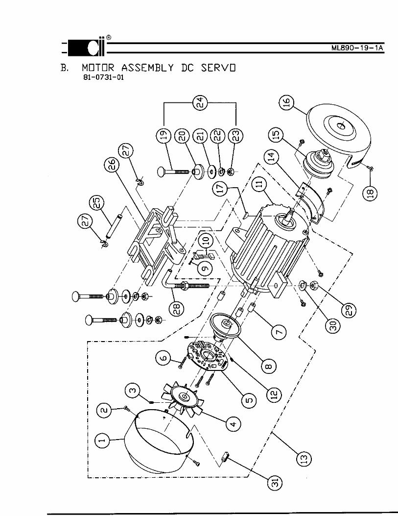
16171819202122232425262728293031
COVERSCREWSCREW, S.S.S.FANPC BOARD, ENCODERSCREWSPACERENCODER DISCSCREWENCODER SENSORMOTOR, DCSCREW, S.S.S.MOTOR/ENCODER ASSEMBLYBELT GUARD, FIXEDPULLEY - 50MMPULLEY - 60MMPULLEY - 65MMPULLEY - 70MMPULLEY - 75MMPULLEY - 80MMPULLEY - 85MMPULLEY - 90MMPULLEY - 95MMPULLEY - 100MMPULLEY - 105MMPULLEY - 110MMPULLEY - 115MMPULLEY - 120MMPULLEY - 125MMPULLEY - 130MMPULLEY - 140MMPULLEY - 150MMBELT GUARD, ADJUSTABLEKEY, PULLEYSCREW M5 X 10 HEX HD.BOLT, CARRAIGESPACERWASHER, FLATWASHER, SPLIT LOCKNUT, HEXHARDWARE KIT, MOTOR MOUNTPINBRACKET, MOTOR MOUNTSNAP RINGBOLT, ADJUSTINGNUT, HEXWASHER, SPLIT LOCKGROMMET
30-4433-0130-4434-0130-4435-0130-4436-0130-4437-0130-4438-0130-4439-0130-4440-0230-4441-0130-4442-0130-4443-0130-4444-0181-0732-0130-4445-0130-4204-5030-4204-6030-4204-6530-4204-7030-4204-7530-4204-8030-4204-8530-4204-9030-4204-95
30-4204-100 30-4204-105 30-4204-110 30-4204-115 30-4204-120 30-4204-125 30-4204-130 30-4204-140 30-4204-15030-4203-0130-4227-0130-4206-0130-4298-0130-4332-0130-4300-0130-4301-0130-4229-0130-4337-0130-4219-0130-4446-0130-4220-0130-4205-0130-4210-0130-4218-0130-4472-01
132113311112111111111111111111111123333311111111
MOTOR ASSEMBLY PARTS LIST, DC SERVO81-0731-01
7-3
®
ML890-19-2C


E. SYNCHRONIZER
7-6
ITEM DESCRIPTION PART NO. QUANTITY
123456789
101112131415161718192021
SYNCHRONIZERCOVER, SYNCHRONIZERSCREW M5 X 12 F.H.M.S.SPACER DISC RETAININGLEDDISC POSITIONERSPACER, DISCDISC, TRIMSCREW M3.5 X SELF TAPSPACERHOUSINGSCREW M4 X 10SHAFT, SYNCHRONIZERSCREW M6 X 8 S.S.S.PC BOARD, SYNCHRONIZERSCREW, PC BOARD MOUNTWASHER, SPLIT LOCKBASESCREW M3 X SELF TAPSCREW M3 X 10BEARING
81-0733-0130-4262-0230-4263-0130-4264-0130-4428-0130-4266-0130-4267-0130-4268-0130-4270-0130-4271-0130-4272-0230-4273-0130-4429-0130-4275-0130-4430-0130-4209-0130-4277-0130-4278-0230-4279-0130-4280-0130-4281-01
111112313112121441221
®
ML890-20A

F. PROGRAMMABLE DISPLAY
G. MISCELLANEOUS PARTS
7-7
ITEM DESCRIPTION PART NO. QUANTITY
1
234
PROGRAMMABLE DISPLAYPROGRAMMABLE DISPLAYBRACKET, MOUNTINGSCREW M4 X 12SCREW
30-4321-01 (890)30-4317-01 (870LCD)30-4286-0130-4287-0130-4288-01
11112
®
ML890-21A