Microwave Oven · Microwave Oven User Manual MOF20110X 01M-8854283200-1117-04 EN

SERVICEMICROWAVE OVEN CONTENTS
MICROWAVE OVEN
1. Precaution
2. Specifications
3. Operating Instructions
4. Disassembly and Reassembly
5. Alignment and Adjustments
6. Troubleshooting
7. Exploded Views and Parts List
8. Schematic Diagrams
9. Wiring Diagram &
Operating Sequence
Manual
CM-1002T
TRANSIMPEX

PRECAUTIONS TO BE OBSERVED BEFORE ANDDURING SERVICING TO AVOID POSSIBLEEXPOSURE TO EXCESSIVE MICROWAVE ENERGY(a) Do not operate or allow the oven to be
operated with the door open.(b) Make the following safety checks on
all ovens to be serviced before activatingthe magnetron or other microwavesource, and make repairs as necessary:(1) Interlock operation,(2) proper door closing,(3) seal and sealing surfaces (arcing,
wear, and other damage),(4) damage to or loosening of hinges
and latches,(5) evidence of dropping or abuse.
(c) Before turning on microwave powerfor any service test or inspection withinthe microwave generatingcompartments, check the magnetron,wave guide or transmission line, andcavity for proper alignment, integrity,and connections.
(d) Any defective or misadjustedcomponents in the interlock, monitor,door seal, and microwave generationand transmission systems shall berepaired, replaced, or adjusted byprocedures described in this manualbefore the oven is released to theowner.
(e) A Microwave leakage check to verifycompliance with the Federalperformance standard should beperformed on each oven prior torelease to the owner.
�����
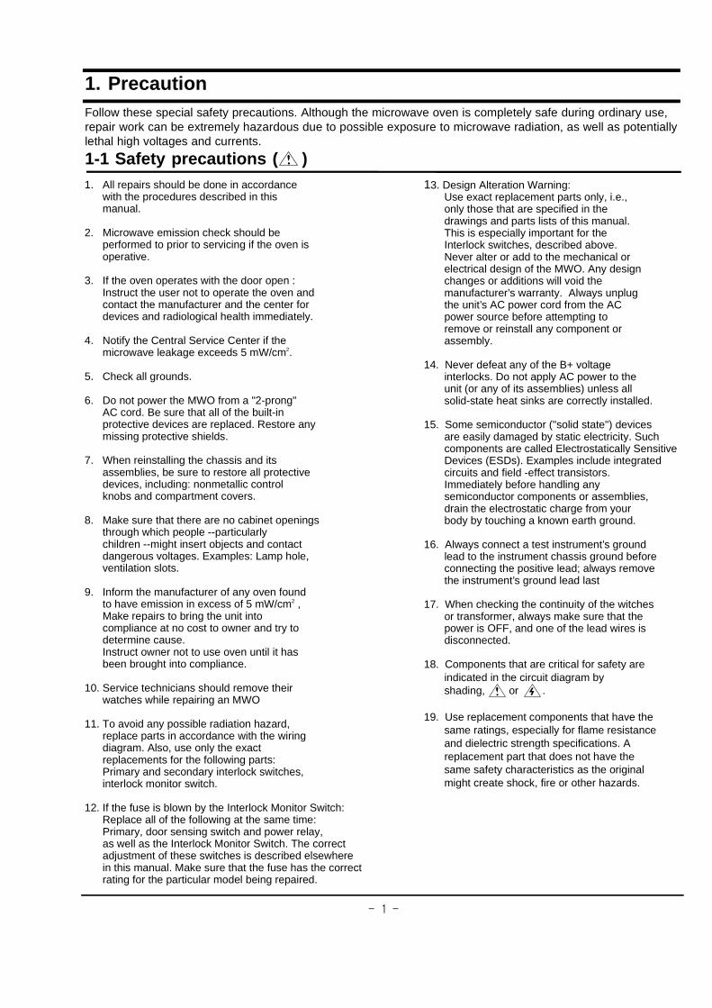
1. PrecautionFollow these special safety precautions. Although the microwave oven is completely safe during ordinary use,repair work can be extremely hazardous due to possible exposure to microwave radiation, as well as potentiallylethal high voltages and currents.
1-1 Safety precautions ( )1. All repairs should be done in accordance
with the procedures described in thismanual.
2. Microwave emission check should beperformed to prior to servicing if the oven isoperative.
3. If the oven operates with the door open :Instruct the user not to operate the oven andcontact the manufacturer and the center fordevices and radiological health immediately.
4. Notify the Central Service Center if themicrowave leakage exceeds 5 mW/cm2.
5. Check all grounds.
6. Do not power the MWO from a "2-prong"AC cord. Be sure that all of the built-inprotective devices are replaced. Restore anymissing protective shields.
7. When reinstalling the chassis and itsassemblies, be sure to restore all protectivedevices, including: nonmetallic controlknobs and compartment covers.
8. Make sure that there are no cabinet openingsthrough which people --particularlychildren --might insert objects and contactdangerous voltages. Examples: Lamp hole,ventilation slots.
9. Inform the manufacturer of any oven foundto have emission in excess of 5 mW/cm2 ,Make repairs to bring the unit intocompliance at no cost to owner and try todetermine cause.Instruct owner not to use oven until it hasbeen brought into compliance.
10. Service technicians should remove theirwatches while repairing an MWO
11. To avoid any possible radiation hazard,replace parts in accordance with the wiringdiagram. Also, use only the exactreplacements for the following parts:Primary and secondary interlock switches,interlock monitor switch.
12. If the fuse is blown by the Interlock Monitor Switch:Replace all of the following at the same time:Primary, door sensing switch and power relay,as well as the Interlock Monitor Switch. The correctadjustment of these switches is described elsewherein this manual. Make sure that the fuse has the correctrating for the particular model being repaired.
13. Design Alteration Warning:Use exact replacement parts only, i.e.,only those that are specified in thedrawings and parts lists of this manual.This is especially important for theInterlock switches, described above.Never alter or add to the mechanical orelectrical design of the MWO. Any designchanges or additions will void themanufacturer’s warranty. Always unplugthe unit’s AC power cord from the ACpower source before attempting toremove or reinstall any component orassembly.
14. Never defeat any of the B+ voltageinterlocks. Do not apply AC power to theunit (or any of its assemblies) unless allsolid-state heat sinks are correctly installed.
15. Some semiconductor ("solid state") devicesare easily damaged by static electricity. Suchcomponents are called Electrostatically SensitiveDevices (ESDs). Examples include integratedcircuits and field -effect transistors.Immediately before handling anysemiconductor components or assemblies,drain the electrostatic charge from yourbody by touching a known earth ground.
16. Always connect a test instrument’s groundlead to the instrument chassis ground beforeconnecting the positive lead; always removethe instrument’s ground lead last
17. When checking the continuity of the witchesor transformer, always make sure that thepower is OFF, and one of the lead wires isdisconnected.
18. Components that are critical for safety areindicated in the circuit diagram byshading, or .
19. Use replacement components that have thesame ratings, especially for flame resistanceand dielectric strength specifications. Areplacement part that does not have thesame safety characteristics as the originalmight create shock, fire or other hazards.

�����
1-2 Special High Voltage Precautions1. High Voltage Warning
Do not attempt to measure any of the highvoltages --this includes the filament voltageof the magnetron. High voltage is presentduring any cook cycle.
Before touching any components or wiring,always unplug the oven and discharge thehigh voltage capacitor (See Figure 1-1)
2. The high-voltage capacitor remains chargedabout 30 seconds after disconnection. Shortthe negative terminal of the high-voltagecapacitor to to the oven chassis. (Use ascrewdriver.)
3. High voltage is maintained within specifiedlimits by close-tolerance, safety-relatedcomponents and adjustments. If the highvoltage exceeds the specified limits, checkeach of the special components.
PRECAUTION
There exists HIGH VOLTAGE ELECTRICITYwith high current capabilities in the circuits ofthe HIGH VOLTAGE TRANSFORMERsecondary and filament terminals. It isextremely dangerous to work on or nearthese circuits with the oven energized.DO NOT measure the voltage in the high voltagecircuit including filament voltage of magnetron.
PRECAUTIONServicemen should remove their watcheswhenever working close to or replacing themagnetron.
PRECAUTIONNever touch any circuit wiring with your hand norwith uninsulated tool during operation.
H.V.Capacitor
Negative Terminal
Screwdriver
Discharge the High Voltage Capacitors
before servicing
Note : Touch chassis side first then short
to the high voltage capacitor terminal by
using a screwdriver.
�����
2. Specifications
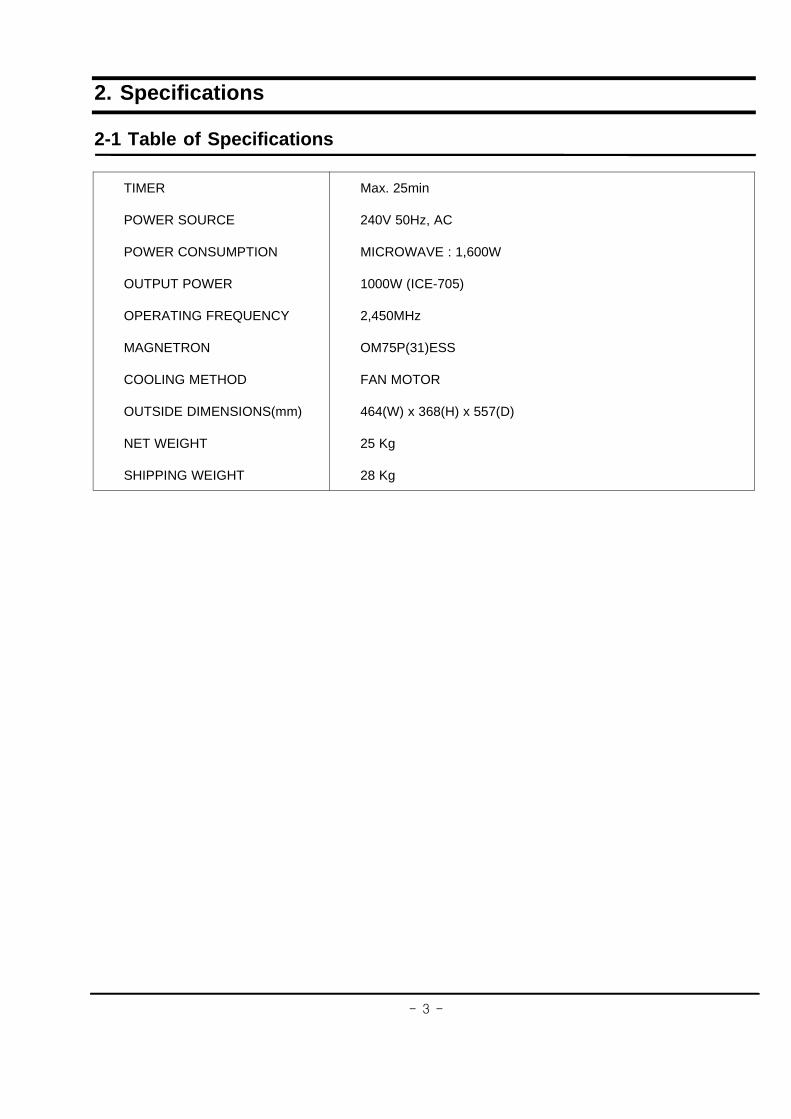
2-1 Table of Specifications
TIMER
POWER SOURCE
POWER CONSUMPTION
OUTPUT POWER
OPERATING FREQUENCY
MAGNETRON
COOLING METHOD
OUTSIDE DIMENSIONS(mm)
NET WEIGHT
SHIPPING WEIGHT
Max. 25min
240V 50Hz, AC
MICROWAVE : 1,600W
1000W (ICE-705)
2,450MHz
OM75P(31)ESS
FAN MOTOR
464(W) x 368(H) x 557(D)
25 Kg
28 Kg
�����
3. Operating Instructions
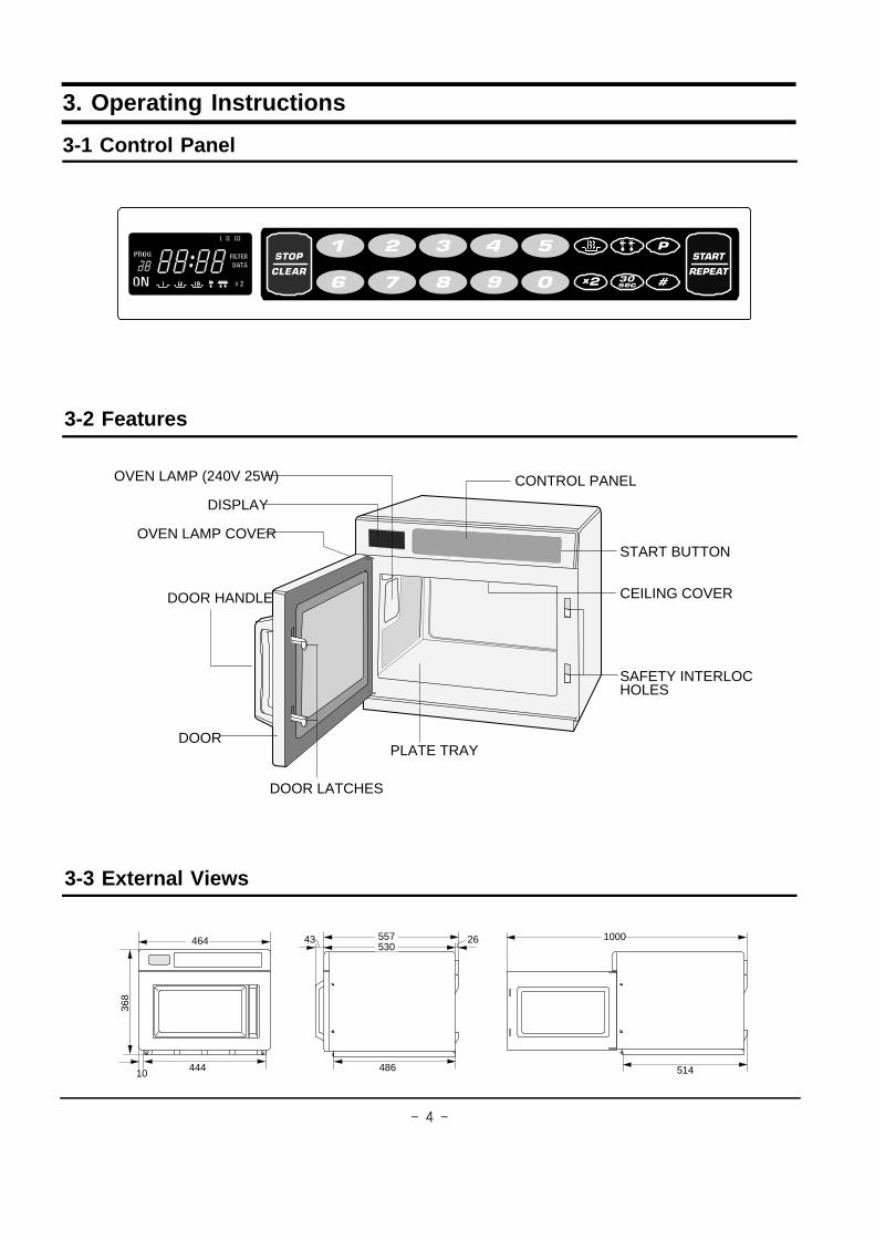
3-1 Control Panel
3-3 External Views
3-2 Features
OVEN LAMP (240V 25W)
DISPLAY
OVEN LAMP COVER
DOOR HANDLE
DOOR
START BUTTON
CONTROL PANEL
CEILING COVER
SAFETY INTERLOCKHOLES
DOOR LATCHES
PLATE TRAY
514
1000
368
44410
464
486
53043 26557
�����
3-4 Operation Guide
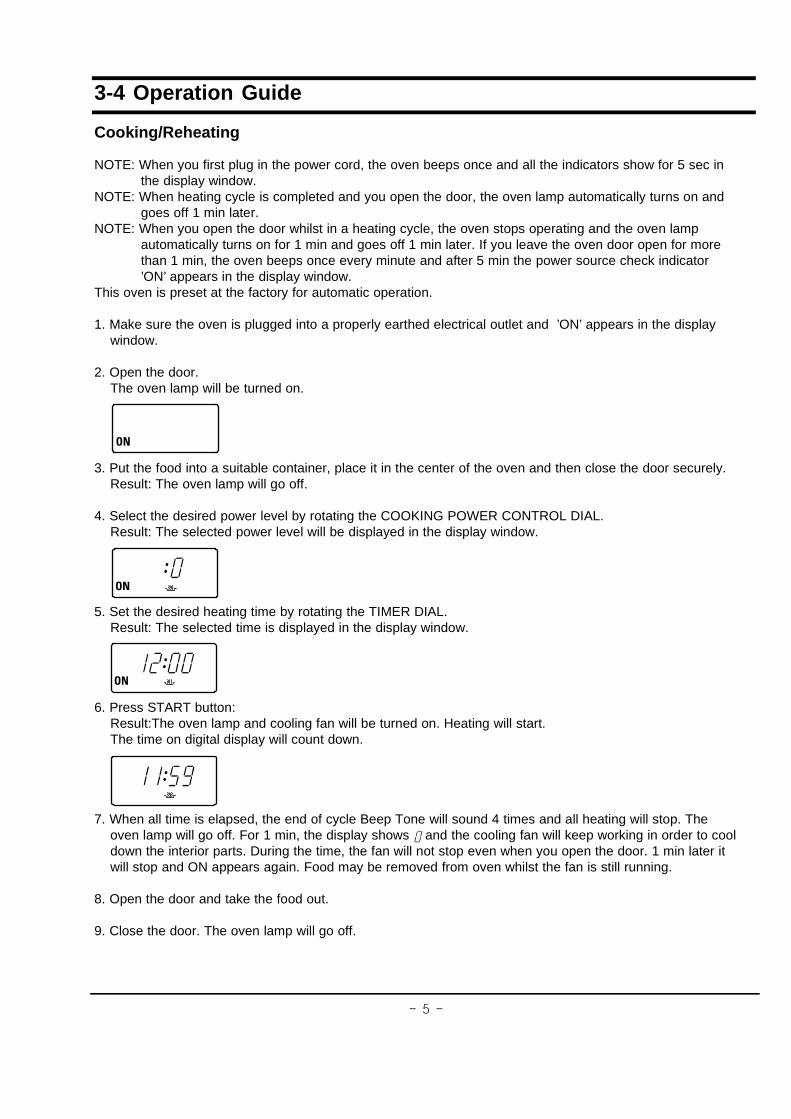
Cooking/Reheating
NOTE: When you first plug in the power cord, the oven beeps once and all the indicators show for 5 sec inthe display window.
NOTE: When heating cycle is completed and you open the door, the oven lamp automatically turns on andgoes off 1 min later.
NOTE: When you open the door whilst in a heating cycle, the oven stops operating and the oven lampautomatically turns on for 1 min and goes off 1 min later. If you leave the oven door open for morethan 1 min, the oven beeps once every minute and after 5 min the power source check indicator’ON’ appears in the display window.
This oven is preset at the factory for automatic operation.
1. Make sure the oven is plugged into a properly earthed electrical outlet and ’ON’ appears in the displaywindow.
2. Open the door.The oven lamp will be turned on.
3. Put the food into a suitable container, place it in the center of the oven and then close the door securely.Result: The oven lamp will go off.
4. Select the desired power level by rotating the COOKING POWER CONTROL DIAL.Result: The selected power level will be displayed in the display window.
5. Set the desired heating time by rotating the TIMER DIAL.Result: The selected time is displayed in the display window.
6. Press START button:Result:The oven lamp and cooling fan will be turned on. Heating will start.The time on digital display will count down.
7. When all time is elapsed, the end of cycle Beep Tone will sound 4 times and all heating will stop. Theoven lamp will go off. For 1 min, the display shows and the cooling fan will keep working in order to cooldown the interior parts. During the time, the fan will not stop even when you open the door. 1 min later itwill stop and ON appears again. Food may be removed from oven whilst the fan is still running.
8. Open the door and take the food out.
9. Close the door. The oven lamp will go off.

�����
3-4 Operation Guide (continued)
Using the Defrost Feature
NOTE: When the oven was operating for longer than 25 min under Defrosting cycle, you can NOT changethe power level from Defrosting to Heating(Cooking/Reheating) mode.
*Only use containers that are microwave-safe.
1. Open the door.
2. Place the frozen food in the centre of the plate tray.
3. Close the door.
4. Press the Defrost selector pad to set DEFROST HIGH ( ) or DEFROST LOW ( ) as you wish.Result: The selected DEFROST indicator appears in the display.
5. Press the Number pads to set the defrosting time. (Max. 50 min)
6. Press button.Result: Defrosting begins.
NOTE: It is not possible to set a defrosting time for longer than 50min. The defrost indicator will flash and itis advisable to press CANCEL and enter a new defrost level and time.
Repeat Feature
You can repeat the previous cooking setting (regardless of manual or automatic memory heating) bypressing the START button. The oven starts with exactly the same heating time and power level that wereused in the last operation.NOTE: The repeat feature will be cancelled once the power source is cut off.
Using +30sec Pad
This is a ONE TOUCH COOK pad.By touching the +30sec pad once, you can start heating instantly.You can increase the cooking time by pressing the +30sec pad while heating is being done.A cooking time increases by 30 seconds at each press on +30sec pad. But it can not exceed the maximumtime. Like traditional cooking, you may find that, depending on the food’s characteristics or your tastes, youhave to adjust the cooking times slightly.Before operating the oven, times can be increased/decreased using either the time pads or +30sec button.During the operating, time may only be added by using the +30sec button.

����
3-4 Operation Guide (continued)
Memory Pads Programming
1. Hold down PROGRAM LOCK pad and then press PROGRAM pad. Hold together for 2 sec.Be sure to press the pads firmly.Result: PROG indicator appears in the digital display.
2. Press appropriate NUMBER pad for the desired memory number.Result: Selected memory program code appears below the PROGRAM indicator.
3. Select power level by pressing the POWER LEVEL pad.Result:Default power level HIGH appears in the display at first press of the POWER LEVEL pad.Press the POWER LEVEL pad one or more times until you get the desired power level.
4. Press NUMBER pads to set the cooking time.Result: The maximum time according to each cooking power level can be referred to in the title ’PowerLevels and Time Variations’on page 8. The NUMBER pads will not operate or respond when you press acooking time exceeding the maximum value.
NOTE: It is not possible to set a cooking time for longer than the maximum time allowed on the chosenprogram. The power level indicator will flash and it is advisable to press CANCEL and to enter a newpower level and cooking time.
5. Hold down PROGRAM LOCK pad and then press PROGRAM pad. Hold together for 2 sec once again.Result: PROG indicator and memory number indicator blink 3 times in the digital display with a beepsound. And then the display goes blank.Caution: Be sure to press the pads firmly in the right position.
6. When you want to program more, repeat the procedures above again.Memory programs are available up to 20 items. Make sure the unit is properly programmed.After programming is finished, all you have to do for memory cooking is to press the NUMBER pad. Thenthe selected memory program automatically starts cooking.

����
3-4 Operation Guide (continued)
How to Operate Memory Cooking
After having finished memory programming, just press the NUMBER pad of the memory number you want toselect. The oven will automatically start heating according to the pre-programmed cooking time and powerlevel after a short delay (5 sec).
1. Make sure the oven is plugged into a properly earthed electrical outlet and ?N?appears in the displaywindow.
2. Open the door.The oven lamp will be turned on.
3. Put the food into a suitable container, place it in the centre of the oven and then close the door securely.Result: The oven lamp will go off.
4. Press NUMBER pad.Result: After 2 seconds, the selected memory program automatically starts heating.
Stopping the Cooking
You can stop cooking at any time so that you can:� Check the food� Turn the food over or stir it� Leave it to stand
To stop the cooking;
* Temporarily: Open the door or press pad once.Result: Cooking stops. To resume cooking, close the door and press again.
* Completely: Press the pad twice.Result: The cooking settings are cancelled.
If you want to cancel any cooking settings before starting cooking, simply press CANCEL pad once.

�����
3-4 Operation Guide(continued)
Power Levels and Time Variations
The power level function enables you to adapt the amount of energy dissipated and thus the time required tocook or reheat your food, according to its type and quantity. You can choose between the power levelsbelow.
Power Level Percentage CM-1001T
HIGH( ) 100% 1000W
MEDIUM( ) 70% 700W
LOW( ) 50% 500W
HIGH DEFROST( ) 30% 300W
LOW DEFROST( ) 18% 180W
You cannot set the cooking time longer than maximum value allowed to each specific power level.(see below.)
Power Level Max. Time
HIGH 25 min
MEDIUM 40 min
LOW 40 min
HIGH DEFROST 50 min
LOW DEFROST 50 min

������
H. V. Trans
4 Mounting Bolts
LVT
4. Disassembly and Reassembly4-1 Replacement of Magnetron
Remove the magnetron including the shield case,permanent magnet, choke coils and capacitor (allof which are contained in one assembly).
1. Remove the outer panel.NOTE: Before servicing, make sure to discharge
electric charge remaining on the highvoltage capacitors or wait for more than5 min.
2. Remove the back cover.3. Disconnect all lead wires from the magnetron.4. Remove screws securing the duct-MGT and
duct-fan.5. Remove the nut-flanges securing the
magnetron by using a box wrench.6. Take out the magnetron very carefully.NOTE1: When removing the magnetron, make
sure that its antenna does not hit anyadjacent parts, or it may be damaged.
NOTE2: When replacing the magnetron, besure to remount the magnetron gasketin the correct position and make surethe gasket is in good condition.(See page 19 for adjustmentinstructions.)
4-2 Replacement of High Voltage Transformer
1. Discharge the high voltage capacitor.2. Disconnect all the leads.3. Remove the mounting bolts securing the HVT.4. Reconnect the leads correctly and firmly.
Magnetron
Duct-Fan
Nut-Flange
Duct-MGT-L

������
Upper Hinge
Lower HingeSpring-Key
2 screws securingDoor Handle
Key-DoorPin-Key
Screen B
Door C
Door E Ass’y
Decoration Door
Decoration Door Cover
Door HandleDoor Handle Cover
4-3 Replacement of Door Assembly4-3-1 Removal of Door Assembly
NOTE: Be sure to wear gloves when you disassemble or assemble the parts.
1. Remove hex bolts securing the upper hinge and lower hinge. Then remove the door assembly.2. Insert the flat screwdriver or thin metal plate into the gap between the door E and door C to remove
Door C from the door assembly.3. Remove 2 screws securing the Door Handle.4. Unbend the 6 metal tabs around the trim of Decoration Door Cover.5. Remove 3 screws securing the Door E Ass?.6. Remove upper hinge and lower hinge.7. Remove Decoration Door, Screen B, Key-Door, Spring-Key, Pin-Key as needed.
4-3-2 Removal of Door Handle
1. Remove hex bolts securing the upper hinge and lower hinge. Then remove the door assembly.2. Insert the flat screwdriver or thin metal plate into the gap between the door E and door C to
remove Door C from the door assembly.NOTE: Be careful when handling Door C as is fragile.NOTE: The thickness of the flat screwdriver or thin metal plate inserted into the gap should be
0.5mm or less.3. Remove 2 screws securing the Door Handle to the Door E Assy.4. Unbend the 2 metal tabs at both ends of the Door Handle to remove the Door Handle Cover
from the Door Handle.
4-3-3 Reassembly Test
1. When mounting the door to the oven, be sure to adjust the door parallel to the bottom line ofthe oven face plate by moving the upper hinge and lower hinge in the direction necessaryfor proper alignment.
2. Adjust so that the door has no play between the inner door surface and oven front surface.If the door assembly is not mounted properly, microwave energy may leak from the spacebetween the door and oven.
3. Do the microwave leakage test.
After replacement of the defective component parts of the door, reassemble it and follow theinstructions below for proper installation and adjustment so as to prevent an excessive microwaveleakage.

������
4-4 Replacement of Fuse and H.V.Fuse1. Disconnect the oven from the power source.2. Remove defective fuse from Noise filter.3. When replacing the fuse, be sure to use an
exact replacement part. If new fuse blows outagain after replacement, check the primaryinterlock switch, door sensing switch andinterlock monitor switch.
4. When the above three switches operateproperly, check if any other part such as thecontrol circuit board, fan motor or high voltagetransformer is defective.
4-5 Replacement of Drive Motor & Ass’y Stirrer
4-5-1 Replacement of Drive Motor
1. Remove outer panel and back-cover.2. Disconnect all the lead wires from the drive motor.3. Remove a screw securing the drive motor.4. When replacing the drive motor, be sure to
remount it in the correct position with the coupler.5. Connect all the leads to the drive motor.6. Screw the drive motor to the bracket motor with
a screw driver.
4-5-2 Replacement of Ass? Stirrer
1. Remove a screw securing the drive motor.2. Open the door.3. Hold side stoppers of ceiling cover (Ass’y Stirrer
Cover) with both hands and pull them in and down.4. Take the ceiling cover out of the oven cavity.5. Remove plastic clips securing the Ass’y Stirrer.
Caution: When removing the Ass? Stirrer Cover,be sure to be extremely careful about theexposed inside components on the top ofthe oven cavity. If any of them aredeformed, abnormal symptom can happensuch as arcing or sparks during operation.
H.V.Fuse
10A Fuse
1.6A Fuse
Screw
Drive Motor
Ass’y Stirrer
Ass’y Stirrer CoverPlastic Clips
To remove Ass’y Stirrer Cover: Holdside stoppers of ceiling cover with bothhands and pull them in and down.
������
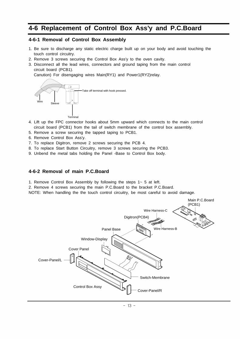
4-6 Replacement of Control Box Ass’y and P.C.Board
4-6-1 Removal of Control Box Assembly
1. Be sure to discharge any static electric charge built up on your body and avoid touching thetouch control circuitry.
2. Remove 3 screws securing the Control Box Ass’y to the oven cavity.3. Disconnect all the lead wires, connectors and ground taping from the main control
circuit board (PCB1).Canution) For disengaging wires Main(RY1) and Power1(RY2)relay.
4. Lift up the FPC connector hooks about 5mm upward which connects to the main controlcircuit board (PCB1) from the tail of switch membrane of the control box assembly.
5. Remove a screw securing the tapped taping to PCB1.6. Remove Control Box Ass’y.7. To replace Digitron, remove 2 screws securing the PCB 4.8. To replace Start Button Circuitry, remove 3 screws securing the PCB3.9. Unbend the metal tabs holding the Panel -Base to Control Box body.
4-6-2 Removal of main P.C.Board
1. Remove Control Box Assembly by following the steps 1~ 5 at left.2. Remove 4 screws securing the main P.C.Board to the bracket P.C.Board.NOTE: When handling the the touch control circuitry, be most careful to avoid damage.
Take off terminal with hook pressed.
Wire
Terminal
Sleeve
Control Box Assy
Switch-Membrane
Digitron(PCB4)
Window-Display
Cover-Panel/L
Cover-Panel/R
Main P.C.Board(PCB1)
Panel Base
Cover Panel
Wire Harness-B
Wire Harness-C

������
4-7 Replacement of Fan Motor
1. Remove the outer panel and back-cover.2. Discharge the high voltage capacitor.3. Remove all the lead wires from Magnetron
and High Voltage Capacitor.4. Remove 2 screws securing the duct fan.5. Remove 2 screws securing the Supporter-
Fan Mount.6. Lift the Fan Motor Ass’y slightly left and pull
it out.7. Remove lead wires and connectors.8. Turn the fan motor ass’y over so that the
bracket side is up.9. Remove 2 screws securing the Fan Motor.
4-8 Replacement of Tray
1. Open the door.2. Remove the tray by inserting a thin metal tool into
the gap between the oven wall and the tray siliconcover.
3. Insert the new tray by tilting it across the ovencavity.
4. Firstly fix the front part (refers to the place wherethe silicon cover is thinner than the other 3 edges)and then place the backward part carefully andfirmly.
NOTE: Be careful when you handle the tray since itis fragile.
4-9 Replacement of Lamp
NOTE: You don’t need to remove the outer panelor other parts in order to replace a lamp.
1. Remove a screw securing the lamp cover.2. Remove the lamp by rotating it clockwise.3. Replace with a new lamp by rotating it counter-
clockwise.
NOTE : If it is necessary to replace the lampholder, you can disconnect lead wires bypushing down on the hole of lead wiresusing a long pointed tool.
Supporter-Fan-Mount
Duct-Fan
Fan Motor
Lamp HolderLamp Cover
Outer Panel
Tray
������
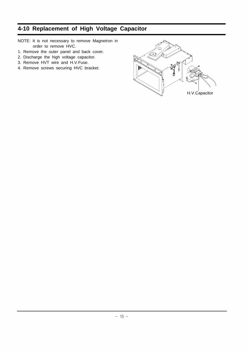
4-10 Replacement of High Voltage Capacitor
NOTE: It is not necessary to remove Magnetron inorder to remove HVC.
1. Remove the outer panel and back cover.2. Discharge the high voltage capacitor.3. Remove HVT wire and H.V.Fuse.4. Remove screws securing HVC bracket.
H.V.Capacitor

������
5. Alignment and Adjustments
5-1 High Voltage Transformer1. Remove connectors from the transformer terminals
and check continuity.2. Normal resistance readings are as follows:
Filament Terminals
(Room temperature = 20�)
5-2 Low Voltage Transformer1. The low voltage transformer is located on the
base plate.2. Remove the low voltage transformer from the
base plate and check continuity.3. Normal resistor reading is shown in the table.
5-3 MagnetronContinuity checks can indicate only an openfilament or a short magnetron. To diagnose anopen filament or short magnetron :
1. Isolate the magnetron from the circuit bydisconnecting its leads.
2. A continuity check across the magnetron filamentterminals should indicate one ohm or less.
3. A continuity check between each filament terminaland magnetron case should read open.
5-4 High Voltage Capacitor1. Check continuity of the capacitor with the meter set at the highest resistance scale.2. Once the capacitor is charged, a normal capacitor shows continuity for a short time, and then
indicates 9M�.3. A shorted capacitor will show continuous continuity.4. An open capacitor will show constant 9M�.5. Resistance between each terminal and chassis should read infinite.
PRECAUTION1. High voltage is present at the high voltage terminals during any cook cycle.2. It is neither necessary nor advisable to attempt measurement of the high voltage.3. Before touching any oven components or wiring, always unplug the oven from its power source and
discharge the high voltage capacitor.
Terminal Resistance
Secondary
Filament
Primary
Approx. 75�
Approx. 0�
Approx. 1.2�
Terminal Resistance Wire
1~2(input)
3~4(output 20V)
5~6(output 3.2V)
Approx. 296�
Approx. 5.1�
Approx. 1.1�
WHT
RED
YEL
Filament Terminals
PrimaryTerminals
SecondaryTerminal
Magnetron Antenna
GasketPlate
Cooling Fins
�����
5-5 High Voltage Diode1. Isolate the diode from the circuit by disconnecting its leads.2. With the ohm-meter set at the highest resistance scale, measure across the diode terminals.
Reverse the meter leads and read the resistance. A meter with 6V, 9V or higher voltagebatteries should be used to check the front-to back resistance of the diode (otherwise an infiniteresistance may be read in both directions). The resistance of a normal diode will be infinite in onedirection and several hundred K� in the other direction.
5-6 Main Relay and Power Control Relay1. The relays are located on the PCB Ass’y. Isolate them from the main circuit by disconnecting
the leads.2. Operate the microwave oven with a water load in the oven. Set the power level to high.3. Check continuity between terminals of the relays after Start pad is pressed.
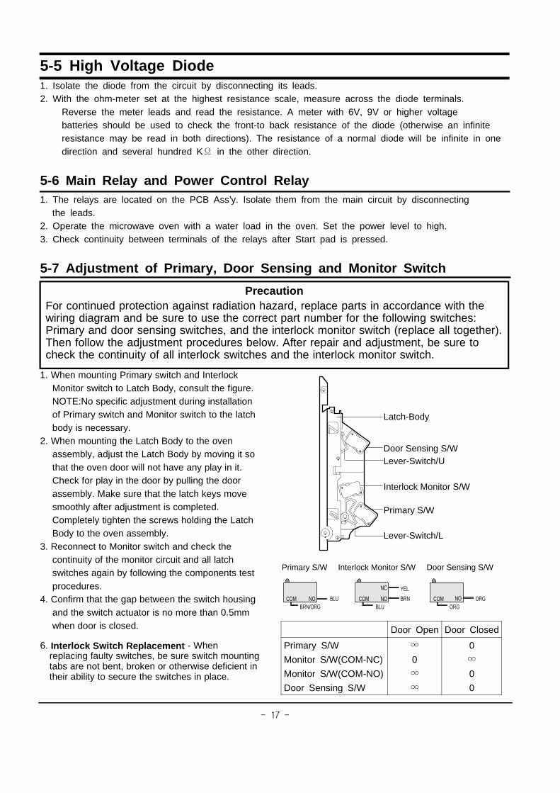
5-7 Adjustment of Primary, Door Sensing and Monitor Switch
1. When mounting Primary switch and InterlockMonitor switch to Latch Body, consult the figure.NOTE:No specific adjustment during installationof Primary switch and Monitor switch to the latchbody is necessary.
2. When mounting the Latch Body to the ovenassembly, adjust the Latch Body by moving it sothat the oven door will not have any play in it.Check for play in the door by pulling the doorassembly. Make sure that the latch keys movesmoothly after adjustment is completed.Completely tighten the screws holding the LatchBody to the oven assembly.
3. Reconnect to Monitor switch and check thecontinuity of the monitor circuit and all latchswitches again by following the components testprocedures.
4. Confirm that the gap between the switch housingand the switch actuator is no more than 0.5mmwhen door is closed.
6. Interlock Switch Replacement - Whenreplacing faulty switches, be sure switch mountingtabs are not bent, broken or otherwise deficient intheir ability to secure the switches in place.
PrecautionFor continued protection against radiation hazard, replace parts in accordance with thewiring diagram and be sure to use the correct part number for the following switches:Primary and door sensing switches, and the interlock monitor switch (replace all together).Then follow the adjustment procedures below. After repair and adjustment, be sure tocheck the continuity of all interlock switches and the interlock monitor switch.
Door Open Door Closed
Primary S/W
Monitor S/W(COM-NC)
Monitor S/W(COM-NO)
Door Sensing S/W
�
0
�
�
0
�
0
0
COM NO NO
NC
NOCOM COM
Primary S/W Interlock Monitor S/W Door Sensing S/W
YEL
BLU BRN ORGBRN/ORG BLU ORG
Latch-Body
Door Sensing S/WLever-Switch/U
Interlock Monitor S/W
Primary S/W
Lever-Switch/L
�����
5-8 Output Power of Magnetron
The output power of the magnetron can be measured by performing a water temperature rise test.
Equipment needed :* Two 1-liter cylindrical borosilicate glass vessel (Outside diameter 190 mm)* One glass thermometer with mercury columnNOTE: Check line voltage under load. Low voltage will lower the magnetron output. Make all temperature andtime tests with accurate equipment.1. Fill the one liter glass vessel with water.2. Stir water in glass vessel with thermometer, and record glass vessel’s temperature ("T1", 10�1�).3. After moving the water into another glass vessel, place it in the center of the cooking tray. Set the oven to
high power and operate for 45 seconds. (3 seconds included as a holding time of magnetron oscillation)4. When heating is finished, stir the water again with the thermometer and measure the temperature ("T2").
5. Subtract T1 from T2. This will give you the water temperature rise. (�T)6. The output power is obtained by the following formula;
Output Power = 4.187 x 1000 x �T x 0.88 x MC x (T2-T0) 45 : Heating Time(sec)42 4.187 : Coefficient for Water
1000 : Water (cc)� T : Temperature Rise (T2-T1)MC : Cylindrical borosilicate glass weightT0 : Room temperature
7. Normal temperature rise for this model is 9� to 11� at ’HIGH’.NOTE 1: Variations or errors in the test procedure will cause a variance in the temperature rise. Additionalpower test should be made if temperature rise is marginal.NOTE 2: Output power in watts is computed by multiplying the temperature rise (step 5) by a factor of 90times of centigrade temperature.
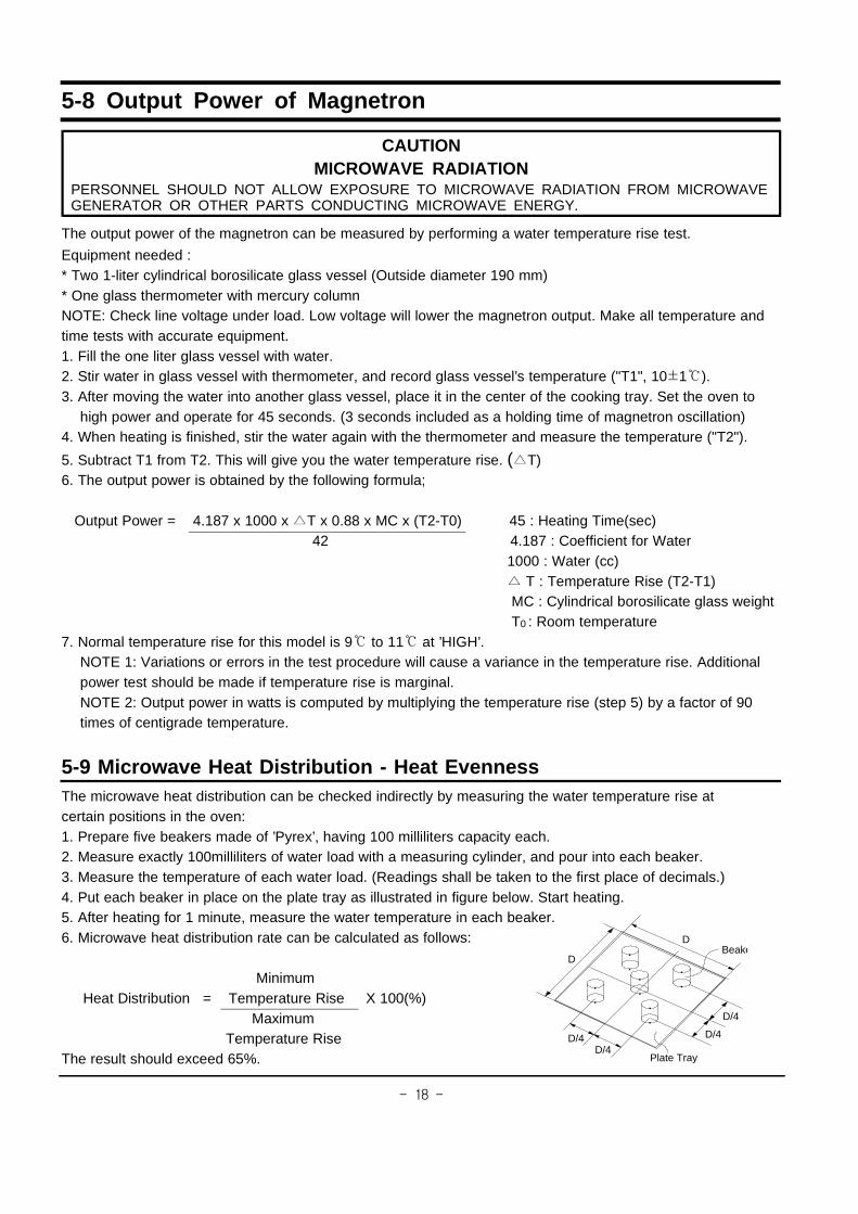
5-9 Microwave Heat Distribution - Heat EvennessThe microwave heat distribution can be checked indirectly by measuring the water temperature rise atcertain positions in the oven:1. Prepare five beakers made of ’Pyrex’, having 100 milliliters capacity each.2. Measure exactly 100milliliters of water load with a measuring cylinder, and pour into each beaker.3. Measure the temperature of each water load. (Readings shall be taken to the first place of decimals.)4. Put each beaker in place on the plate tray as illustrated in figure below. Start heating.5. After heating for 1 minute, measure the water temperature in each beaker.6. Microwave heat distribution rate can be calculated as follows:
MinimumHeat Distribution = Temperature Rise X 100(%)
MaximumTemperature Rise
The result should exceed 65%.
CAUTIONMICROWAVE RADIATION
PERSONNEL SHOULD NOT ALLOW EXPOSURE TO MICROWAVE RADIATION FROM MICROWAVEGENERATOR OR OTHER PARTS CONDUCTING MICROWAVE ENERGY.
D
D
D/4
D/4
D/4D/4
Plate Tray
Beake
������
Probe
Spacer Cone
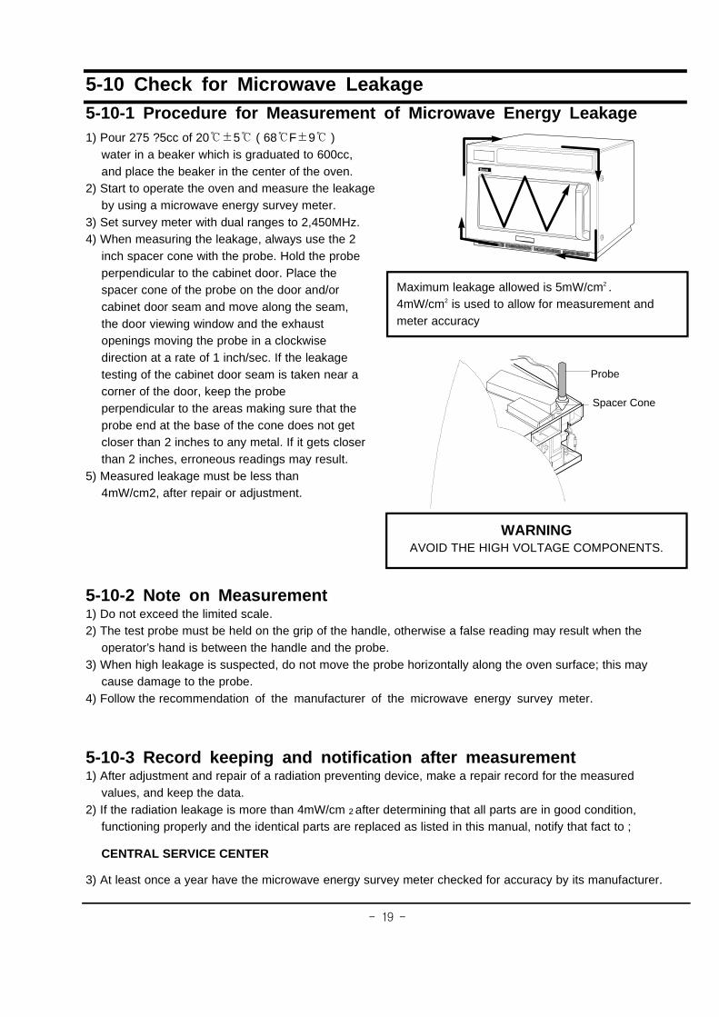
5-10 Check for Microwave Leakage5-10-1 Procedure for Measurement of Microwave Energy Leakage1) Pour 275 ?5cc of 20��5� ( 68�F�9� )
water in a beaker which is graduated to 600cc,and place the beaker in the center of the oven.
2) Start to operate the oven and measure the leakageby using a microwave energy survey meter.
3) Set survey meter with dual ranges to 2,450MHz.4) When measuring the leakage, always use the 2
inch spacer cone with the probe. Hold the probeperpendicular to the cabinet door. Place thespacer cone of the probe on the door and/orcabinet door seam and move along the seam,the door viewing window and the exhaustopenings moving the probe in a clockwisedirection at a rate of 1 inch/sec. If the leakagetesting of the cabinet door seam is taken near acorner of the door, keep the probeperpendicular to the areas making sure that theprobe end at the base of the cone does not getcloser than 2 inches to any metal. If it gets closerthan 2 inches, erroneous readings may result.
5) Measured leakage must be less than4mW/cm2, after repair or adjustment.
5-10-2 Note on Measurement1) Do not exceed the limited scale.2) The test probe must be held on the grip of the handle, otherwise a false reading may result when the
operator’s hand is between the handle and the probe.3) When high leakage is suspected, do not move the probe horizontally along the oven surface; this may
cause damage to the probe.4) Follow the recommendation of the manufacturer of the microwave energy survey meter.
5-10-3 Record keeping and notification after measurement1) After adjustment and repair of a radiation preventing device, make a repair record for the measured
values, and keep the data.2) If the radiation leakage is more than 4mW/cm 2 after determining that all parts are in good condition,
functioning properly and the identical parts are replaced as listed in this manual, notify that fact to ;
CENTRAL SERVICE CENTER
3) At least once a year have the microwave energy survey meter checked for accuracy by its manufacturer.
Maximum leakage allowed is 5mW/cm2 .4mW/cm2 is used to allow for measurement andmeter accuracy
WARNINGAVOID THE HIGH VOLTAGE COMPONENTS.
������
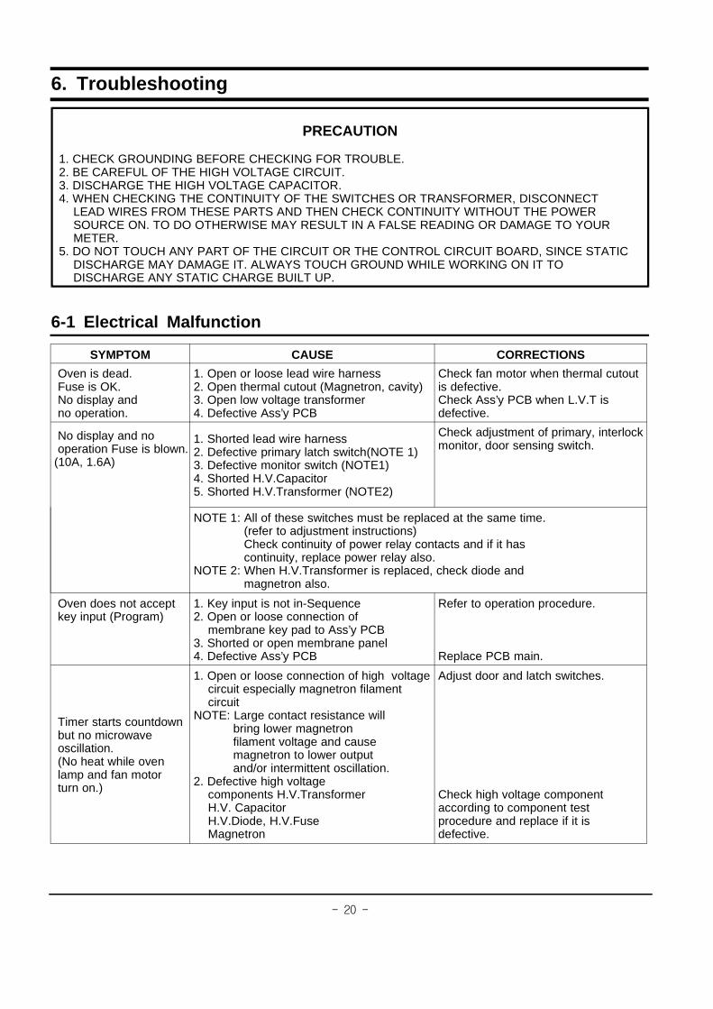
6. Troubleshooting
6-1 Electrical Malfunction
SYMPTOM CAUSE CORRECTIONS
Oven is dead.Fuse is OK.No display andno operation.
1. Open or loose lead wire harness2. Open thermal cutout (Magnetron, cavity)3. Open low voltage transformer4. Defective Ass’y PCB
Check fan motor when thermal cutoutis defective.Check Ass’y PCB when L.V.T isdefective.
No display and nooperation Fuse is blown.
(10A, 1.6A)
1. Shorted lead wire harness2. Defective primary latch switch(NOTE 1)3. Defective monitor switch (NOTE1)4. Shorted H.V.Capacitor5. Shorted H.V.Transformer (NOTE2)
Check adjustment of primary, interlockmonitor, door sensing switch.
NOTE 1: All of these switches must be replaced at the same time.(refer to adjustment instructions)Check continuity of power relay contacts and if it hascontinuity, replace power relay also.
NOTE 2: When H.V.Transformer is replaced, check diode andmagnetron also.
Oven does not acceptkey input (Program)
1. Key input is not in-Sequence2. Open or loose connection of
membrane key pad to Ass’y PCB3. Shorted or open membrane panel4. Defective Ass’y PCB
Refer to operation procedure.
Replace PCB main.
Timer starts countdownbut no microwaveoscillation.(No heat while ovenlamp and fan motorturn on.)
1. Open or loose connection of high voltagecircuit especially magnetron filamentcircuit
NOTE: Large contact resistance willbring lower magnetronfilament voltage and causemagnetron to lower outputand/or intermittent oscillation.
2. Defective high voltagecomponents H.V.TransformerH.V. CapacitorH.V.Diode, H.V.FuseMagnetron
Adjust door and latch switches.
Check high voltage componentaccording to component testprocedure and replace if it isdefective.
PRECAUTION
1. CHECK GROUNDING BEFORE CHECKING FOR TROUBLE.2. BE CAREFUL OF THE HIGH VOLTAGE CIRCUIT.3. DISCHARGE THE HIGH VOLTAGE CAPACITOR.4. WHEN CHECKING THE CONTINUITY OF THE SWITCHES OR TRANSFORMER, DISCONNECT
LEAD WIRES FROM THESE PARTS AND THEN CHECK CONTINUITY WITHOUT THE POWERSOURCE ON. TO DO OTHERWISE MAY RESULT IN A FALSE READING OR DAMAGE TO YOURMETER.
5. DO NOT TOUCH ANY PART OF THE CIRCUIT OR THE CONTROL CIRCUIT BOARD, SINCE STATICDISCHARGE MAY DAMAGE IT. ALWAYS TOUCH GROUND WHILE WORKING ON IT TODISCHARGE ANY STATIC CHARGE BUILT UP.

������
6-1 Electrical Malfunction(continued)
SYMPTOM CAUSE CORRECTIONS
Oven lamp goes off 1. Loose lead wire or open lampfilament
1. Misadjustment of latch switch2. Defective primary latch switch
Tighten lamp lead wire or replacewith a new lamp
Microwave output is low;.Oven takes longer time tocook food.(No heat while oven lampand ventilation)
1. Decrease in power source voltage.2. Open or loose wiring of magnetron
filament circuit.(Intermittent oscillation)3. Aging of magnetron4. Defective high voltage components
H.V.TransformerH.V. CapacitorH.V.Diode, H.V.FuseMagnetron
Consult electrician.
Check high voltage componentaccording to component testprocedure and replace if defective.
Oven does not operate andreturn to the plugged in mode.
Defective Ass’y PCB Replace PCB main.
Loud buzzing noise can beheard.
1. Loose fan and Fan motor2. Loose screws on H.V.Transformer3. Shorted H.V.Diode4. Loose or missing screws on
Cover-Back.
Tighten screws of Fan motor.Tighten screws of H.V.Transformer.Replace H.V.Diode.Tighten screws of Cover-Back
Drive motor not work.(Ass’y stirrer does notrotate.)
1. Open or loose wiring of turntable motor.2. Defective turntable motor.3. Defective ass’y stirrer
Check the wire of drive motorReplace drive motor.Replace ass’y stirrer
Oven stops operation duringcooking
1. Operation of thermal cutout(Magnetron or Cavity)
2. Fan motor does not rotate.
Adjust door and latch switches.
Replace Fan motor.
Sparks 1. Metallic ware or cooking dishestouching on the oven wall.
2. Ceramic ware trimmed with gold orsilver powder also causes sparks.
Inform the customer of proper use..Do not use any type of cookwarewith metallic trimming.
Uneven cooking Uneven intensity of microwave due to itscharacteristics.
Wrap thinner parts of the food withaluminum foil.Use plastic wrap or cover with a lid.Stir once or twice while cookingfoods such as soup, cocoa, or milk.
Noise from the turntablemotor when it starts tooperate.
Noise may result from the motor. Replace turntable motor.
Oven can program buttimer does not start.
Defective circuitry of Start functionof Main P.C.B Ass’y.
Loose lead wires.
Check circuitry of Start functionof Main P.C.B Ass’y and replace ifdefective.Adjust or repair loose wires.

������
6-2 Error Codes & Corrections
Code Cause Corrections
E11. Improper input power freqency.
2. Defective Ass’y Main P.C.B
Check if power frequency is 50Hz.
Replace Ass’y Main P.C.B or MICOM
E5 1. Memory IC(EEPROM IC) failure
2. MICOM failure
Check Memory (IC3) and replace if defective.
Replace Ass’y Main P.C.B or MICOM.
������
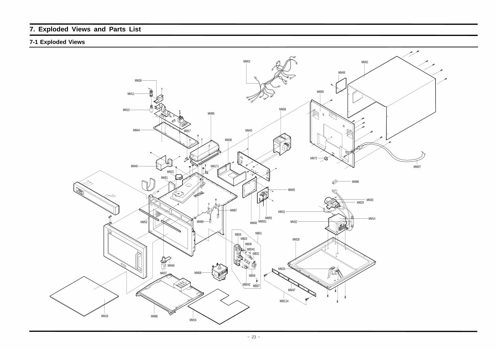
7. Exploded Views and Parts List
7-1 Exploded Views
MM87
MB06
MM01
MM07
MM49
MM08
MM14
MM29
MM32
MM31
MM33
MM89 MM48
MM05
MM46
MM37
MM86MM16
MM18
MB03
MB08
MM30
MM88
MB042
MM55MM551
MM72
MM59
MM06
MM43
MM38
MM171MM40
MM53
MM44
MM22
MM51
MM10
MM11
MM36
MM85
MM17
MM03
MB05
MB041MB02
MB01
MM28
MB07
MM47
MM114

������
7-2 Main Parts List
No. Code No. Description Specification Q’ty RemarkMB01 DE93-20097F ASSY BODY LATCH CM1019/1029,EUROPE 1MB02 3405-000175 SWITCH-MICRO 250V,15A,200gf,SPST-NO 1MB03 3405-000178 SWITCH-MICRO 250V,15A,200gf,SPST-NO 1
MB041 DE66-90107A LEVER-SWITCH/U PBT,CM-1819,-,-,-,-,- 1MB042 DE66-90108A LEVER-SWITCH/L PBT,CM-1819,-,-,-,-,- 1MB05 DE66-40062A LATCH-BODY PP,CM-1819,-,-,-,- 1MB06 DE72-60106A GUIDE-S/W -,ABS,BLK,-,-,- 2 LATCHMB07 DE61-00066A SPRING-Q MSWR,PI0.8,-,-,-,-,CM1819/1829,- 1MB08 3405-001055 SWITCH-MICRO 125/250VAC,16A,200GF,SPST-NO 1MM01 DE70-30123A PANEL-OUTER -,STS430,T0.6,CM-1819,-,-,-,- 1MM03 DE39-00051A WIRE HARNESS-A -,230V50HZ,SEMI-COMMERCIAL,-,CM1019/1029 1MM05 DE96-00003B ASSY NOISE FILTER SN-1830,250V15A,-,-,-,-,- 1MM06 DE91-50093J ASSY-MOTOR FAN -,230V50HZ,2300RPM,CM-1001T,- 1MM07 DE39-00296A ASSY POWER CORD CM-1001T,-,1.0MM,-,-,-,KOCE-3,-,-,-,-,-,-,- 1MM08 OM75P(20)ESS ASSY-MAGNETRON OM75P(20)ESS 1MM10 4713-000168 LAMP-INCANDESCENT 230V,-,25W,ORG,-,-,- 1MM11 DE47-40029A SOCKET-LAMP 250V2A,22.23,E14,BJB,-,-,- 1
MM114 6011-001140 BOLT-STUD M4,L8,Ni PLT,BSW 2MM14 DE26-00016A TRANS-H.V SHV-1830EC,230V50HZ,2375V/3.20V,-,DY 1MM16 DE71-60424A COVER-CEILING -,MICA_SHEET,T0.5,W348,L319,-,CM-1819,- 2MM17 DE47-20009A THERMOSTAT PW2N-520PB,160/60,250V/7.5A,H, 1
MM171 DE47-20169A THERMOSTAT PW-2N(100/60,H,23.8,250V/7.5A, 1MM18 DE92-90488A ASSY-TRAY CERAMIC CM-1819,-,-,-,-,- 1MM22 DE31-10164C MOTOR-SYNCHRONOUS M2LJ29A702,220/240V50/60HZ,-,29.1/34.9RPM,FREE 1MM28 DE80-10113C BASE-PLATE CM1819,SECC1,-,-,-,-,- 1MM29 2501-001014 C-OIL 1.05uF,2100V,BK,35X54X85,20mm 1MM30 DE61-50120A BRACKET-HVC -,SECC,T0.6,W62,L72,-,- 1MM31 DE91-70063A ASSY-HVD V2M6,PI9.0,0.05MT,-,- 1MM32 DE91-70061A ASSY-H.V.FUSE THV060T-0800-H,5KV/0.80A,WHT 1MM33 DE26-20162A TRANS-L.V SLV-1829E,230,19.7/3.1V,50Hz,4 1MM36 DE61-90318A HOLDER-LAMP SECC,T0.8,W134,L40.5,-,-,-,-,- 1MM37 DE69-90054A CLIP-STIRRER PFA,5mm,CM1819/29,-,-,- 3MM38 DE72-00025A DUCT-FAN CM1019,S/COMMERCIAL,SECC,T0.6,-,- 1MM40 DE72-50090A DUCT-MGT/L CM-1819,SECC,T0.5,-,-,-,- 1MM43 DE61-30189A SUPPORTER-FAN-MOUNT SECC,T1.0,CM-1819,-,-,-,- 1MM44 DE61-50520A BRACKET-PCB -,SECC,T0.8,CM-1819,-,-,- 1MM46 DE92-90515A ASSY-STIRRER CM-1819,CM-1829,-,-,-,- 1MM47 DE92-90516B ASSY-BRACKET FILTER CM1819,-,-,-,-,- 1MM48 DE61-50568A BRACKET-SUPPORT -,SECC/ALCOAT,T0.6,W100,L100,-,- 1MM49 DE71-60422A COVER-LAMP -,STS430,T0.6,CM-1819,-,-,-,- 1MM51 DE63-90190B CUSHION-LAMP CM1819/29,PUT-FOAM,T7.0,W100,L120,-,- 1MM53 DE01-00095A FILM-LAMP 1MM55 3601-000448 FUSE-CARTRIDGE 250V,10A,SLOW-BLOW,CERAMIC,6.35x31.8mm 1
MM551 3601-001126 FUSE-CARTRIDGE 250V,1.6A,FAST-ACTING,CERAMIC,5x20mm 1MM59 DE71-60421A COVER-BACK -,SECC,T0.6,W481.8,L363.9,-,CM-1819,- 1MM72 DE61-50541A BRACKET-EARTH -,SGCC2,T1.0,W15,L8,-,- 1MM85 DE72-50091A DUCT-OVEN -,STS430,T0.4,CM-1819,-,-,- 1MM86 DE71-60423A COVER-STIRRER -,PP,CM-1819,-,-,-,-,- 1MM87 DE93-90112B ASSY-B/RESISTOR 10W LB-TYPE 15OHM,187 TAB-TERMINAL 1MM88 DE73-90027A FERRITE-CORE NI-ZN,T13.8,W21.0,L28.0,BNF-14 1 H.V.TMM89 DE39-00032A WIRE LEAD-R CEMENT -,-,-,-,CM1819/29,47J30W,EUROPE-COMMERCIAL,- 1
������
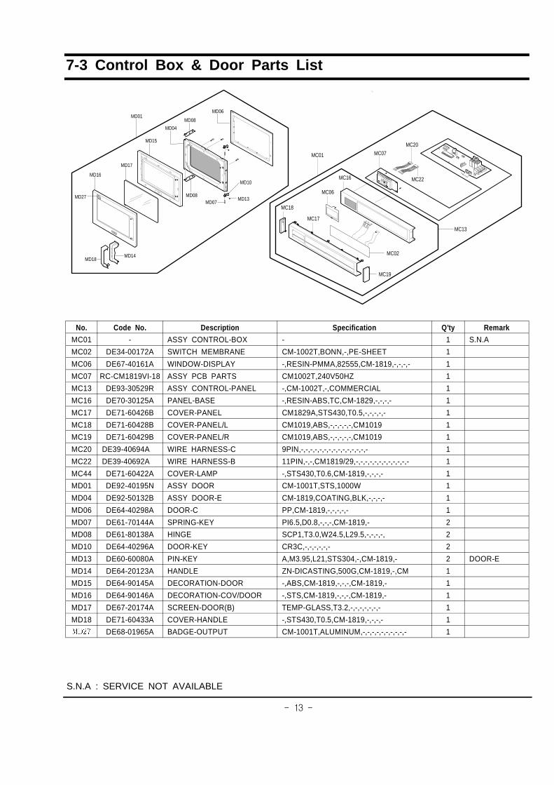
7-3 Control Box & Door Parts List
No. Code No. Description Specification Q’ty Remark
MC01 - ASSY CONTROL-BOX - 1 S.N.A
MC02 DE34-00172A SWITCH MEMBRANE CM-1002T,BONN,-,PE-SHEET 1
MC06 DE67-40161A WINDOW-DISPLAY -,RESIN-PMMA,82555,CM-1819,-,-,-,- 1
MC07 RC-CM1819VI-18 ASSY PCB PARTS CM1002T,240V50HZ 1
MC13 DE93-30529R ASSY CONTROL-PANEL -,CM-1002T,-,COMMERCIAL 1
MC16 DE70-30125A PANEL-BASE -,RESIN-ABS,TC,CM-1829,-,-,-,- 1
MC17 DE71-60426B COVER-PANEL CM1829A,STS430,T0.5,-,-,-,-,- 1
MC18 DE71-60428B COVER-PANEL/L CM1019,ABS,-,-,-,-,-,CM1019 1
MC19 DE71-60429B COVER-PANEL/R CM1019,ABS,-,-,-,-,-,CM1019 1
MC20 DE39-40694A WIRE HARNESS-C 9PIN,-,-,-,-,-,-,-,-,-,-,-,-,-,-,- 1
MC22 DE39-40692A WIRE HARNESS-B 11PIN,-,-,CM1819/29,-,-,-,-,-,-,-,-,-,-,-,- 1
MC44 DE71-60422A COVER-LAMP -,STS430,T0.6,CM-1819,-,-,-,- 1
MD01 DE92-40195N ASSY DOOR CM-1001T,STS,1000W 1
MD04 DE92-50132B ASSY DOOR-E CM-1819,COATING,BLK,-,-,-,- 1
MD06 DE64-40298A DOOR-C PP,CM-1819,-,-,-,-,- 1
MD07 DE61-70144A SPRING-KEY PI6.5,D0.8,-,-,-,CM-1819,- 2
MD08 DE61-80138A HINGE SCP1,T3.0,W24.5,L29.5,-,-,-,-, 2
MD10 DE64-40296A DOOR-KEY CR3C,-,-,-,-,-,- 2
MD13 DE60-60080A PIN-KEY A,M3.95,L21,STS304,-,CM-1819,- 2 DOOR-E
MD14 DE64-20123A HANDLE ZN-DICASTING,500G,CM-1819,-,CM 1
MD15 DE64-90145A DECORATION-DOOR -,ABS,CM-1819,-,-,-,CM-1819,- 1
MD16 DE64-90146A DECORATION-COV/DOOR -,STS,CM-1819,-,-,-,CM-1819,- 1
MD17 DE67-20174A SCREEN-DOOR(B) TEMP-GLASS,T3.2,-,-,-,-,-,-,- 1
MD18 DE71-60433A COVER-HANDLE -,STS430,T0.5,CM-1819,-,-,-,- 1
���� DE68-01965A BADGE-OUTPUT CM-1001T,ALUMINUM,-,-,-,-,-,-,-,-,-,- 1
S.N.A : SERVICE NOT AVAILABLE
MD15
MD04
MD08
MD17
MD16
MD27
MD01
MD08
MD14MD18
MD10
MD13MD07
MD06
MC07
MC20
MC22MC16
MC06
MC19
MC13
MC17
MC18
MC02
MC01
������
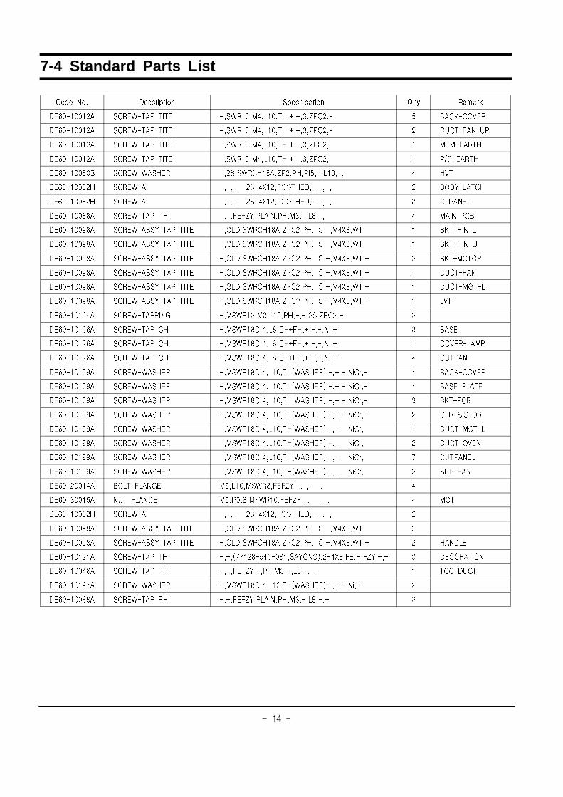
7-4 Standard Parts List
���� ��� ����� ��� ������� ��� �� � �����
����������� ���� �� � � �������������� ������������� � ��������
����������� ���� �� � � �������������� ������������� � �� ��� ��
����������� ���� �� � � �������������� ������������� � ��� ��� �
����������� ���� �� � � �������������� ������������� � � ��� �
��������!�� ��������� ��������!���������������������� � ��
��������!�� ����� �����������"��� �� ����������� � ���#��� �
��������!�� ����� �����������"��� �� ����������� � ������
��������!!� ���� �� �� ��������#����������������!���� � ���� ��
��������$!� �����# �� � � ��%�������!��������� �����"!�� �� � �� ������
��������$!� �����# �� � � ��%�������!��������� �����"!�� �� � �� ������
��������$!� �����# �� � � ��%�������!��������� �����"!�� �� � �� ��� ��
��������$!� �����# �� � � ��%�������!��������� �����"!�� �� � �� ����
��������$!� �����# �� � � ��%�������!��������� �����"!�� �� � �� ��% ��
��������$!� �����# �� � � ��%�������!��������� �����"!�� �� � ��
��������$�� ���� �����% ����������������������������� �
��������$�� ���� �� �� ������!����!��������������&�� � ���
��������$�� ���� �� �� ������!����!��������������&�� � ���������
��������$�� ���� �� �� ������!����!��������������&�� � �� �����
��������$$� ��������� ������!������� �'�����(��������&)�� � ��������
��������$$� ��������� ������!������� �'�����(��������&)�� � ��� ��� �
��������$$� ��������� ������!������� �'�����(��������&)�� � �� ���
��������$$� ��������� ������!������� �'�����(��������&)�� � ���� ��
��������$$� ��������� ������!������� �'�����(��������&)�� � �� ��% ��
��������$$� ��������� ������!������� �'�����(��������&)�� � �� �����
��������$$� ��������� ������!������� �'�����(��������&)�� * �� �����
��������$$� ��������� ������!������� �'�����(��������&)�� � ������
����������� ��� �����%� ����������������#���������� �
����������� �� �����%� �����+!�����������#���������� � �%
��������!�� ����� �����������"��� �� ����������� �
��������$!� �����# �� � � ��%�������!��������� �����"!�� �� �
��������$!� �����# �� � � ��%�������!��������� �����"!�� �� � ������
����������� ���� �� � ����'**��!������!���#��%(����"!��������#���� � ����� ���
����������� ���� �� �� ��������#������������!���� � ����
��������$*� ��������� ������!������� �'�����(��������&�� �
��������!!� ���� �� �� ��������#����������������!���� �

������
8. P.C.B Diagrams
8-1 P.C.B Diagrams

������
8-2 P.C.B Parts List
Code No. Description Specification Q’ty Remark
3501-001155 RELAY-MINIATURE 24VDC,200MW,3000MA,1FORMA,10MS,10MS 3 RY3,RY4,RY6
3501-001209 RELAY-POWER 24V DC,0.53W,-,1FORMA,9.3MS,10MS 2 RY1,RY2
3708-000525 CONNECTOR-FPC/FFC/PIC 10P,2.54mm,STRAIGHT,SN 1 CN5
3711-000616 CONNECTOR-HEADER BOX,11P,1R,2.5mm,STRAIGHT,SN 2 CN10,CN12
3711-001154 CONNECTOR-HEADER BOX,9P,1R,2.5mm,STRAIGHT,SN 2 CN9,CN11
DE07-10088A VF DISPLAY SVM-06MM29,REDDISHORG/GRN,6G,5, 1 DSP1
DE09-00108A IC MICOM TMP87PM14F,OTP-32K,QFP,8BIT-64PIN,- 1 IC1
DE13-20016A IC-VOLT REGU KA7805A,TO-220AB,1A,0/125C,-,- 1 RG1
DE39-40692A WIRE HARNESS-B 11PIN,-,-,CM1819/29,-,-,-,-,-,-,-,-,-,-,-,- 1 WIRE1
DE39-40694A WIRE HARNESS-C 9PIN,-,-,-,-,-,-,-,-,-,-,-,-,-,-,- 1 WIRE2
DE61-90178A HOLDER-DIGITRON -,NY66,-,-,-,-,- 1 DSP1
0401-001083 DIODE-SWITCHING MM4148,100V,150MA,LL-34,TP 15 D04~D08,D13~D23
0402-001080 DIODE-RECTIFIER GF1G,400V,1A,DO-214BA,TP 4 D01~D03,D10
0403-000537 DIODE-ZENER 1N4749A,24V,5%,1W,DO-41,TP 2 ZD2,ZD3
0403-001288 DIODE-ZENER ZMM55C5V1,4.8-5.4V,500MW,LL-34,TP 2 ZD1,ZD4
0501-000465 TR-SMALL SIGNAL MMBT3904,NPN,350MW,SOT-23,TP,30-300 1 TR1
0504-001080 TR-DIGITAL KRC246S,NPN,200mW,2.2K/10K,SOT-23,TP 9 TR2,TR5,TR7~TR13
1103-001096 IC-EEPROM 24LC04B,2x256Kx8BIT,SOP,8P,150 1 IC3
1202-000141 IC-VOLTAGE COMP. 7033,SOT-89,3P,-,SINGLE,0V,-,P 1 IC2
2001-001077 R-CARBON(S) 150OHM,5%,1/2W,AA,TP,2.4X6.4MM 2 R06,R07
2003-000236 R-METAL OXIDE 270ohm,5%,2W,AA,TP,6x16mm 1 R05
2004-000729 R-METAL 3.9Kohm,1%,1/8W,AA,TP,1.8x3.2m 1 R14
2007-000277 R-CHIP 100KOHM,1%,1/10W,DA,TP,2012 1 R15
2007-000300 R-CHIP 10KOHM,5%,1/10W,DA,TP,2012 5 R10,R17~R20
2007-000300 R-CHIP 10KOHM,5%,1/10W,DA,TP,2012 5 R48~R50,R54,R55
2007-000451 R-CHIP 180OHM,5%,1/8W,DA,TP,3216 1 R43
2007-000468 R-CHIP 1KOHM,5%,1/10W,DA,TP,2012 7 R09,R12,R51~R53,R56,R57
2007-000496 R-CHIP 2.2KOHM,5%,1/8W,DA,TP,3216 2 R03,R04
2007-000671 R-CHIP 2KOHM,5%,1/10W,DA,TP,2012 4 R08,R22,R24,R58
2007-000710 R-CHIP 3.9KOHM,5%,1/10W,DA,TP,2012 6 R13,R16,R44~R47
2007-000766 R-CHIP 330OHM,5%,1/10W,DA,TP,2012 7 R41,R42,R60~R65
2007-000931 R-CHIP 470OHM,5%,1/10W,DA,TP,2012 3 R01,R02,R11
2007-000941 R-CHIP 47KOHM,5%,1/10W,DA,TP,2012 7 R21,R23,R25~R28,R59
2203-000260 C-CERAMIC,CHIP 10nF,10%,50V,X7R,TP,2012 2 C21,C22
2203-000444 C-CERAMIC,CHIP 1nF,10%,50V,X7R,TP,2012,- 4 C15~C18
2203-000555 C-CERAMIC,CHIP 0.02NF,5%,50V,C0G,TP,2012 2 C04,C05
2203-001608 C-CERAMIC,CHIP 22nF,+80-20%,50V,Y5V,TP,2012 6 C03,C07,C08,C10,C14,C23
2401-000037 C-AL 470uF,20%,16V,GP,TP,8x11.5,5 1 C06
2401-000173 C-AL 1000uF,20%,35V,GP,TP,13x25,5 1 C01
2401-000466 C-AL 10uF,20%,35V,GP,TP,5x7,5 2 C09,C24
2401-000598 C-AL 1uF,20%,50V,GP,TP,4x7,5 1 C13
2401-000911 C-AL 22uF,20%,16V,GP,TP,5x7,5 1 C12
2401-001415 C-AL 470uF,20%,35V,GP,TP,10x20,5 1 C02
2401-002075 C-AL 4.7uF,20%,50V,GP,TP,5x11,5 1 C11
2801-003933 CRYSTAL-UNIT 8MHz,50ppm,28-AAA,12pF,70ohm,TP 1 XTL1
3002-000198 BUZZER-PIEZO 85DB,24,-,4KHZ,ST 1 BUZ1
3711-000203 CONNECTOR-HEADER 1WALL,2P,1R,7.92MM,STRAIGHT,SN,WHT 1 CN4
3711-000315 CONNECTOR-HEADER 1WALL,4P,1R,7.92MM,STRAIGHT,SN,WHT 2 CN3,CN6
3711-000940 CONNECTOR-HEADER BOX,4P,1R,2.5mm,STRAIGHT,SN 1 CN1
3711-000999 CONNECTOR-HEADER BOX,5P,1R,2.5mm,STRAIGHT,SN 1 CN2
DE39-60001A WIRE-SO COPPER ,PI0.6,SN,T,52MM TAPING_WIRE, 42 J03,J05~J44

������
9. Wiring Diagram & Operating Sequence
9-1 Wiring Diagram

9-2 Description of Operating Sequence
When the oven is set to power level of 100%, 70% or 50% and Def. level 30% or 18%
When the oven is operating under the power level of 100%, 70% or 50% and Def. level 30% or 18% the coilof power relay are energized intermittently by ON and OFF cycle of 30 seconds in order to supply powersource to the High Voltage Transformer and thus to oscillate the magnetron.
The relation between indications on the display window and the output power of the microwave oven is asshown in figure below.
Note : One second inclued as a time for starttng the magnetron oscillation.
CM1019
A : DOOR OPEN, B : DOOR CLOSE, C : START, D : STOPa(b) : 50%-16sec(14sec), 70%-22sec(8sec)
100%
LAMP
B C D A BA
VENT
MAIN
PWR
PWR ab
1MIN
dcPWR
50%, 70%
DEF(30%,18%)
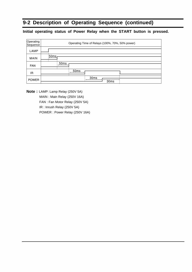
9-2 Description of Operating Sequence (continued)
Initial operating status of Power Relay when the START button is pressed.
Note : LAMP: Lamp Relay (250V 5A)
MAIN : Main Relay (250V 16A)
FAN : Fan Motor Relay (250V 5A)
IR : Inrush Relay (250V 5A)
POWER : Power Relay (250V 16A)
Operating Operating Time of Relays (100%, 70%, 50% power)Sequence

January 2003
Printed in Korea
Code No. :