Microwave Oven · Microwave Oven User Manual MOF20110X 01M-8854283200-1117-04 EN
MICROWAVE OVENSERVICE MANUALMODEL: LMVM2055SB
LMVM2055STLMVM2055SW
CAUTIONBEFORE SERVICING THE UNIT, READ THE SAFETY PRECAUTIONS IN THIS MANUAL.
Website: http://us.lgservice.com
P/NO : 3828W5S6190July, 2005
Printed in Korea
CAUTIONWARNING TO SERVICE TECHNICIANS
PRECAUTIONS TO BE OBSERVED BEFORE ANDDURING SERVICING TO AVOID POSSIBLE EXPOSURE
TO EXCESSIVE MICROWAVE ENERGY
a. Do not operate or allow the oven to be operated with the door open.
b. Make the following safety checks on all ovens to be serviced before activating themagnetron or other microwave source, and make repairs as necessary; (1) Interlockoperation, (2) proper door closing, (3) seal and sealing surfaces (arcing, wear, andother damage), (4) damage to or loosening of hinges and latches, (5) evidence ofdropping or abuse.
c. Before turning on microwave power for any service test or inspection within themicrowave generating compartments, check the magnetron, wave guide ortransmission line, and cavity for proper alignment, integrity, and connections.
d. Any defective or misadjusted components in the interlock, monitor, door seal, andmicrowave generation and transmission systems shall be repaired, replaced, oradjusted by procedures described in this manual before the oven is released to theowner.
e. A Microwave leakage check to verify compliance with the Federal performancestandard should be performed on each oven prior to release to the owner.
• Proper operation of the microwave ovens requires that the magnetron be assembled to the wave guide and cavity.Never operate the magnetron unless it is properly installed.
• Be sure that the magnetron gasket is properly installed around the dome of the tube whenever installing themagnetron.
• Routine service safety procedures should be exercised at all times.
• Untrained personnel should not attempt service without a thorough review of the test procedures and safetyinformation contained in this manual.
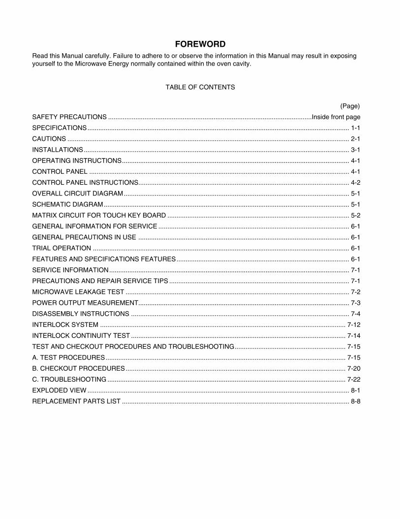
FOREWORDRead this Manual carefully. Failure to adhere to or observe the information in this Manual may result in exposingyourself to the Microwave Energy normally contained within the oven cavity.
TABLE OF CONTENTS
(Page)
SAFETY PRECAUTIONS ................................................................................................................Inside front page
SPECIFICATIONS................................................................................................................................................ 1-1
CAUTIONS ........................................................................................................................................................... 2-1
INSTALLATIONS.................................................................................................................................................. 3-1
OPERATING INSTRUCTIONS............................................................................................................................. 4-1
CONTROL PANEL ............................................................................................................................................... 4-1
CONTROL PANEL INSTRUCTIONS.................................................................................................................... 4-2
OVERALL CIRCUIT DIAGRAM............................................................................................................................ 5-1
SCHEMATIC DIAGRAM....................................................................................................................................... 5-1
MATRIX CIRCUIT FOR TOUCH KEY BOARD .................................................................................................... 5-2
GENERAL INFORMATION FOR SERVICE ......................................................................................................... 6-1
GENERAL PRECAUTIONS IN USE .................................................................................................................... 6-1
TRIAL OPERATION ............................................................................................................................................. 6-1
FEATURES AND SPECIFICATIONS FEATURES............................................................................................... 6-1
SERVICE INFORMATION.................................................................................................................................... 7-1
PRECAUTIONS AND REPAIR SERVICE TIPS ................................................................................................... 7-1
MICROWAVE LEAKAGE TEST ........................................................................................................................... 7-2
POWER OUTPUT MEASUREMENT.................................................................................................................... 7-3
DISASSEMBLY INSTRUCTIONS ........................................................................................................................ 7-4
INTERLOCK SYSTEM ....................................................................................................................................... 7-12
INTERLOCK CONTINUITY TEST ...................................................................................................................... 7-14
TEST AND CHECKOUT PROCEDURES AND TROUBLESHOOTING............................................................. 7-15
A. TEST PROCEDURES.................................................................................................................................... 7-15
B. CHECKOUT PROCEDURES......................................................................................................................... 7-20
C. TROUBLESHOOTING ................................................................................................................................... 7-22
EXPLODED VIEW ................................................................................................................................................ 8-1
REPLACEMENT PARTS LIST ............................................................................................................................. 8-8
1-1
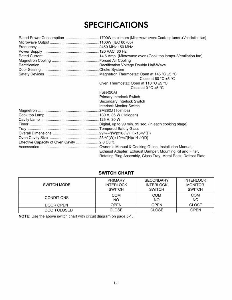
SPECIFICATIONSRated Power Consumption ................................1700W maximum (Microwave oven+Cook top lamps+Ventilation fan)Microwave Output ...............................................1100W (IEC 60705)Frequency ..........................................................2450 MHz ±50 MHzPower Supply .....................................................120 VAC, 60 HzRated Current ....................................................14.5 Amp. (Microwave oven+Cook top lamps+Ventilation fan)Magnetron Cooling .............................................Forced Air CoolingRectification .......................................................Rectification Voltage Double Half-WaveDoor Sealing ......................................................Choke SystemSafety Devices ...................................................Magnetron Thermostat: Open at 145 °C ±5 °C
Close at 60 °C ±5 °C............................................................................Oven Thermostat: Open at 110 °C ±5 °C
Close at 0 °C ±5 °C............................................................................Fuse(20A)............................................................................Primary Interlock Switch............................................................................Secondary Interlock Switch............................................................................Interlock Monitor SwitchMagnetron ..........................................................2M282J (Toshiba)Cook top Lamp ...................................................130 V, 35 W (Halogen)Cavity Lamp .......................................................125 V, 30 WTimer ..................................................................Digital, up to 99 min. 99 sec. (in each cooking stage)Tray ....................................................................Tempered Safety GlassOverall Dimensions ............................................2915/16”(W)x167/16”(H)x153/8”(D)Oven Cavity Size ...............................................231/2”(W)x103/16”(H)x141/2”(D)Effective Capacity of Oven Cavity ......................2.0 Cu.ft.Accessories ........................................................Owner ’s Manual & Cooking Guide, Installation Manual, ............................................................................Exhaust Adapter, Exhaust Damper, Mounting Kit and Filter,............................................................................Rotating Ring Assembly, Glass Tray, Metal Rack, Defrost Plate .
SWITCH CHART
SWITCH MODE
CONDITIONS
DOOR OPEN OPEN OPEN CLOSECLOSE CLOSE OPENDOOR CLOSED
PRIMARYINTERLOCK
SWITCH
SECONDARYINTERLOCK
SWITCH
INTERLOCKMONITORSWITCH
COMNO
COMNO
COMNC
NOTE: Use the above switch chart with circuit diagram on page 5-1.
2-1
CAUTIONSUnlike other appliances, the microwave oven ishigh-voltage and high-current equipment.Though it is free from danger in ordinary use,extreme care should be taken during repair.
MICROWAVE RADIATIONPersonnel should not be exposed to themicrowave energy which may radiate from themagnetron or other microwave generatingdevice if it is improperly used or connection.All input and output microwave connections,waveguide, flange, and gasket must be securenever operate the device without a microwaveenergy absorbing load attached.Never look into an open waveguide or antennawhile the device is energized.
• DO NOT operate on a 2-wire extension cord during repairand use.
• NEVER TOUCH any oven components or wiring duringoperation.
• BEFORE TOUCHING any parts of the oven, alwaysremove the power plug from the outlet.
• Remove your watches whenever working close to orreplacing the Magnetron.
• DO NOT touch any parts of the control panel circuit. Aresulting static electric discharge may damage this P.C.B.
• NEVER operate the oven with no load.• NEVER injure the door seal and front plate of the oven
cavity.• NEVER put iron tools on the magnetron.• NEVER put anything into the latch hole and the interlock
switches area.
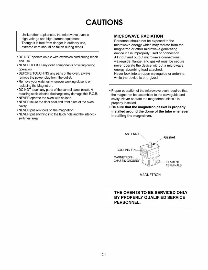
• Proper operation of the microwave oven requires thatthe magnetron be assembled to the waveguide andcavity. Never operate the magnetron unless it is properly installed.
• Be sure that the magnetron gasket is properly installed around the dome of the tube wheneverinstalling the magnetron.
THE OVEN IS TO BE SERVICED ONLYBY PROPERLY QUALIFIED SERVICEPERSONNEL.
GasketANTENNA
COOLING FIN
MAGNETRONCHASSIS GROUND FILAMENT
TERMINALS
MAGNETRON
3-1
INSTALLATIONS
BEFORE YOU BEGIN, READ THE FOLLOWING INSTRUCTIONS COMPLETELY AND CAREFULLY.
PRECAUTIONS ON INSTALLATIONA. Plug the power supply cord into a 120V AC, 60Hz,
single-phase power source with a capacity of atleast 20 amperes.
B. Avoid placing the unit in a location where there isdirect heat or splashing water.
C. Install the unit on the mounting plate firmly.D. Place the unit as far away as possible from TV,
radio, etc.to prevent interference.
GROUNDING INSTRUCTIONSFor personal safety, this appliance must be fullygrounded at all times.
In the event of an electrical short circuit, groundingreduces the risk of electrical shock.The plug must be plugged into an outlet that isproperly installed and grounded.
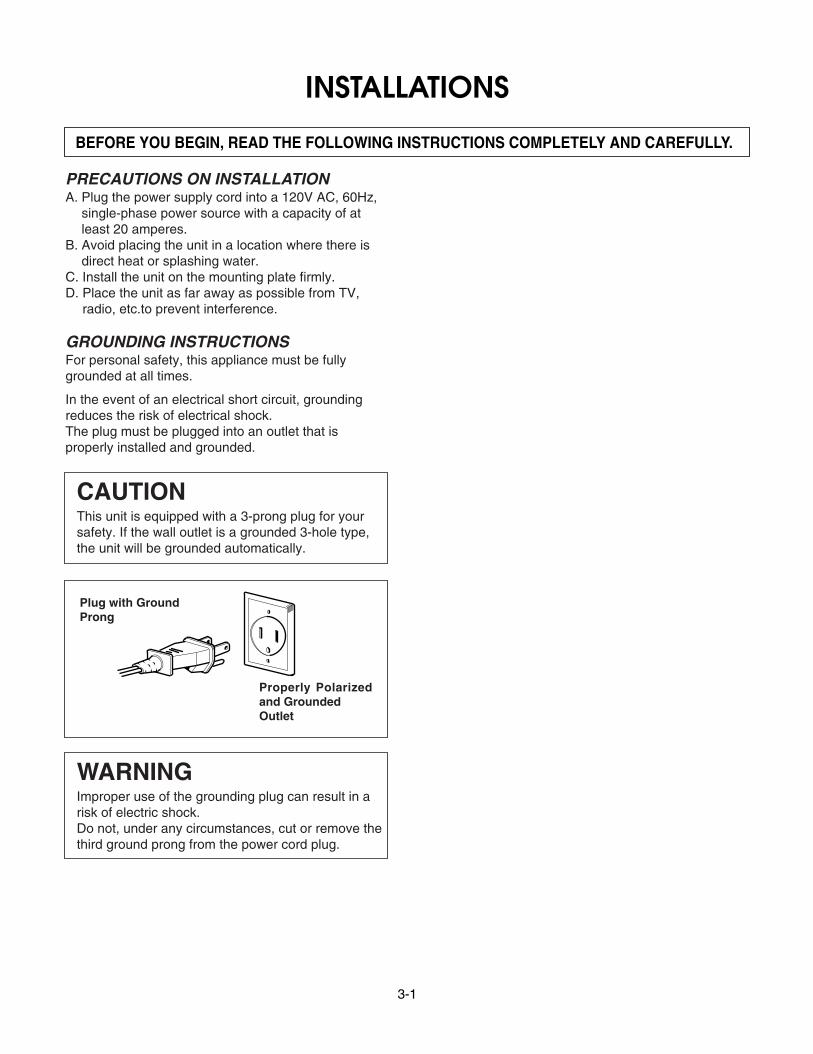
CAUTIONThis unit is equipped with a 3-prong plug for yoursafety. If the wall outlet is a grounded 3-hole type,the unit will be grounded automatically.
WARNINGImproper use of the grounding plug can result in arisk of electric shock.Do not, under any circumstances, cut or remove thethird ground prong from the power cord plug.
Plug with GroundProng
Properly Polarizedand GroundedOutlet
4-1
OPERATING INSTRUCTIONSCONTROL PANEL
14
2623211816
12
15
17 19 20 22 2524
1311
10 16
9873
542
4-2
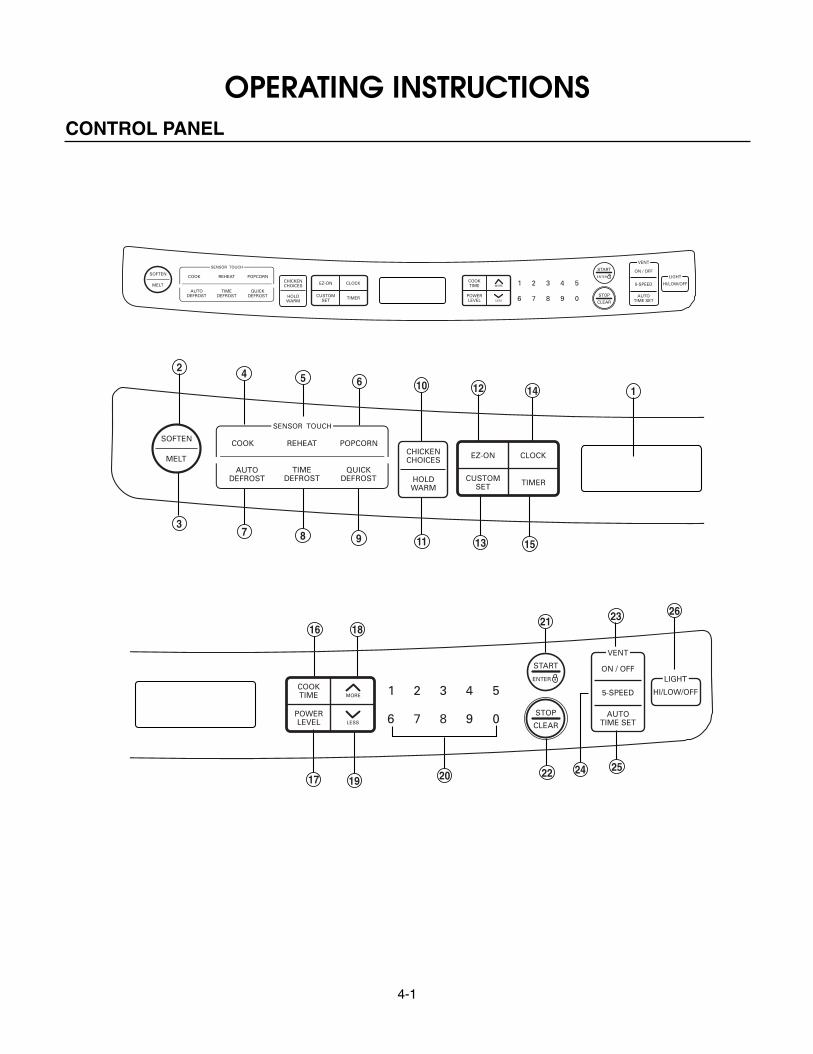
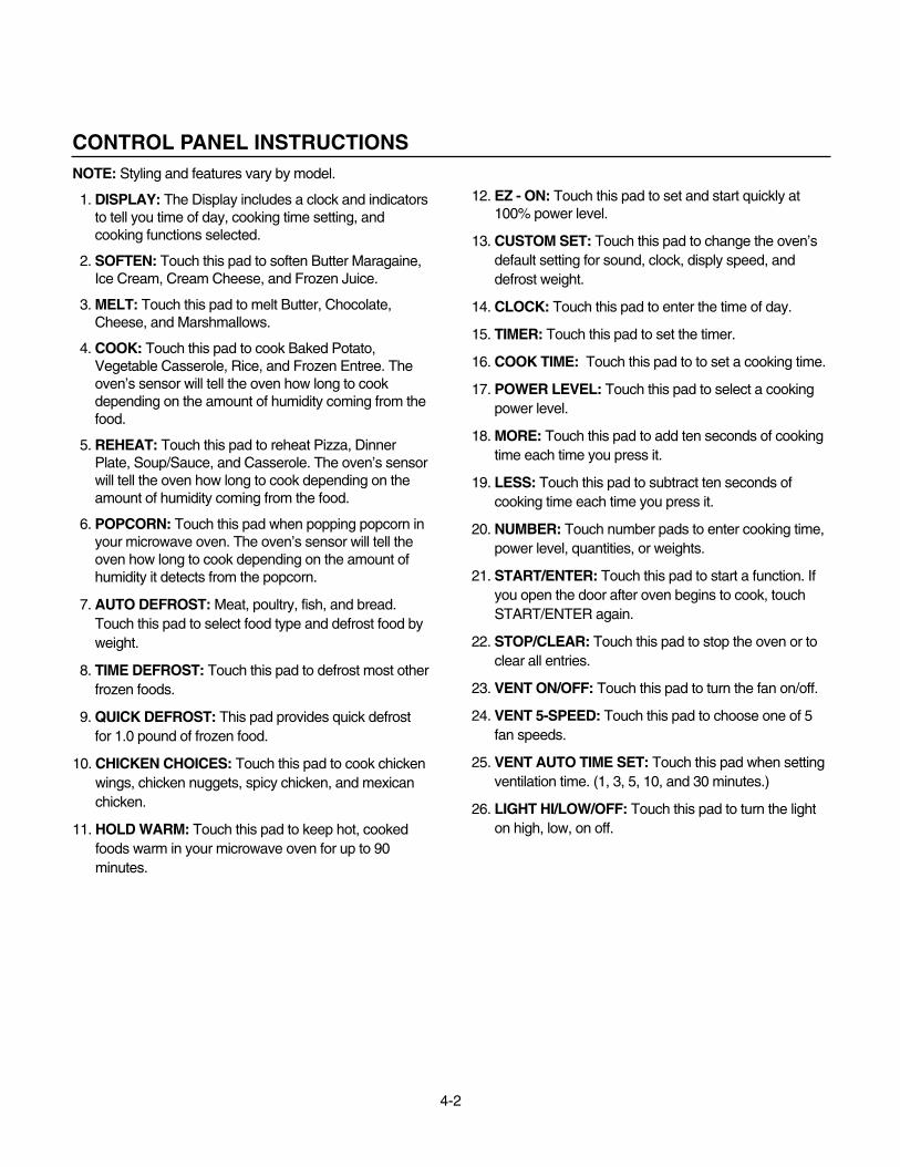
CONTROL PANEL INSTRUCTIONSNOTE: Styling and features vary by model.
1. DISPLAY: The Display includes a clock and indicatorsto tell you time of day, cooking time setting, andcooking functions selected.
2. SOFTEN: Touch this pad to soften Butter Maragaine,Ice Cream, Cream Cheese, and Frozen Juice.
3. MELT: Touch this pad to melt Butter, Chocolate,Cheese, and Marshmallows.
4. COOK: Touch this pad to cook Baked Potato,Vegetable Casserole, Rice, and Frozen Entree. Theoven’s sensor will tell the oven how long to cookdepending on the amount of humidity coming from thefood.
5. REHEAT: Touch this pad to reheat Pizza, DinnerPlate, Soup/Sauce, and Casserole. The oven’s sensorwill tell the oven how long to cook depending on theamount of humidity coming from the food.
6. POPCORN: Touch this pad when popping popcorn inyour microwave oven. The oven’s sensor will tell theoven how long to cook depending on the amount ofhumidity it detects from the popcorn.
7. AUTO DEFROST: Meat, poultry, fish, and bread.Touch this pad to select food type and defrost food byweight.
8. TIME DEFROST: Touch this pad to defrost most otherfrozen foods.
9. QUICK DEFROST: This pad provides quick defrostfor 1.0 pound of frozen food.
10. CHICKEN CHOICES: Touch this pad to cook chickenwings, chicken nuggets, spicy chicken, and mexicanchicken.
11. HOLD WARM: Touch this pad to keep hot, cookedfoods warm in your microwave oven for up to 90minutes.
12. EZ - ON: Touch this pad to set and start quickly at100% power level.
13. CUSTOM SET: Touch this pad to change the oven’sdefault setting for sound, clock, disply speed, anddefrost weight.
14. CLOCK: Touch this pad to enter the time of day.
15. TIMER: Touch this pad to set the timer.
16. COOK TIME: Touch this pad to to set a cooking time.
17. POWER LEVEL: Touch this pad to select a cookingpower level.
18. MORE: Touch this pad to add ten seconds of cookingtime each time you press it.
19. LESS: Touch this pad to subtract ten seconds ofcooking time each time you press it.
20. NUMBER: Touch number pads to enter cooking time,power level, quantities, or weights.
21. START/ENTER: Touch this pad to start a function. Ifyou open the door after oven begins to cook, touchSTART/ENTER again.
22. STOP/CLEAR: Touch this pad to stop the oven or toclear all entries.
23. VENT ON/OFF: Touch this pad to turn the fan on/off.
24. VENT 5-SPEED: Touch this pad to choose one of 5fan speeds.
25. VENT AUTO TIME SET: Touch this pad when settingventilation time. (1, 3, 5, 10, and 30 minutes.)
26. LIGHT HI/LOW/OFF: Touch this pad to turn the lighton high, low, on off.
5-1
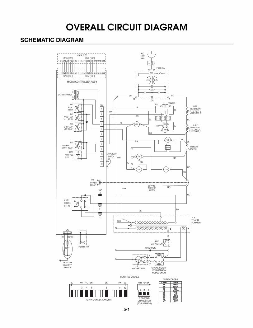
OVERALL CIRCUIT DIAGRAMSCHEMATIC DIAGRAM
5-2
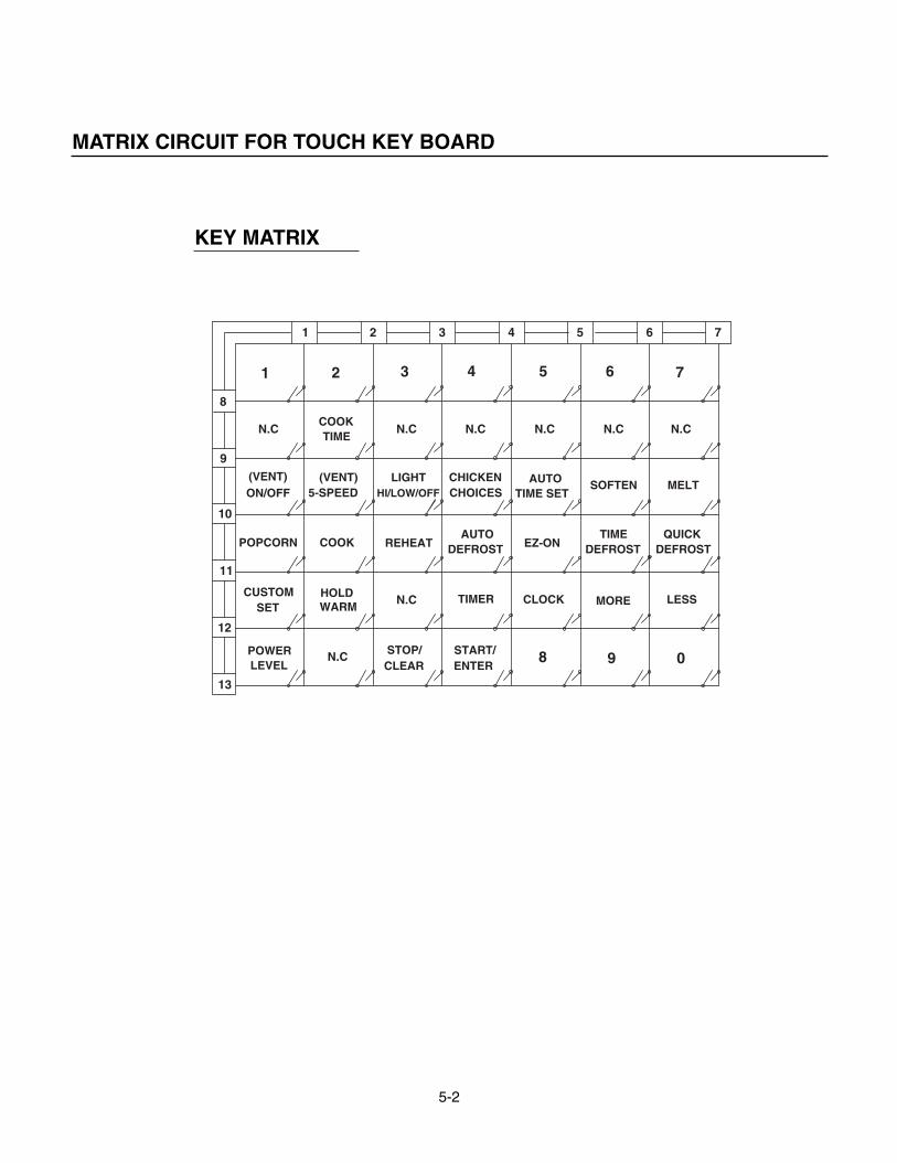
MATRIX CIRCUIT FOR TOUCH KEY BOARD
N.C
SOFTEN
MORE
DEFROSTTIME
CUSTOM HOLD
LEVELPOWER
SET
N.C
WARM
ON/OFF(VENT)
POPCORN COOK
5-SPEED
N.C
(VENT)
TIMECOOK
CLOCK
CLEARSTOP/
N.C
START/ENTER
TIMER
8 9
CHOICESCHICKEN
DEFROST
HI/LOW/OFF
REHEATAUTO
LIGHT
N.C N.C
TIME SETAUTO
N.C
1 2 3 4 5 6
LESS
0
DEFROSTQUICK
N.C
MELT
7
EZ-ON
8
13
12
11
10
9
1 2 3 4 5 6 7
KEY MATRIX
6-1
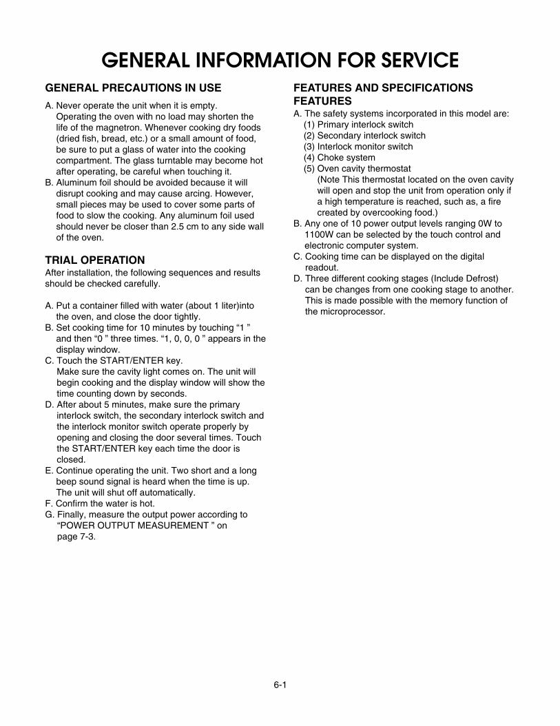
GENERAL INFORMATION FOR SERVICEGENERAL PRECAUTIONS IN USE
A. Never operate the unit when it is empty. Operating the oven with no load may shorten thelife of the magnetron. Whenever cooking dry foods(dried fish, bread, etc.) or a small amount of food, be sure to put a glass of water into the cookingcompartment. The glass turntable may become hotafter operating, be careful when touching it.
B. Aluminum foil should be avoided because it willdisrupt cooking and may cause arcing. However,small pieces may be used to cover some parts offood to slow the cooking. Any aluminum foil usedshould never be closer than 2.5 cm to any side wallof the oven.
TRIAL OPERATIONAfter installation, the following sequences and resultsshould be checked carefully.
A. Put a container filled with water (about 1 liter)intothe oven, and close the door tightly.
B. Set cooking time for 10 minutes by touching “1 ”and then “0 ” three times. “1, 0, 0, 0 ” appears in thedisplay window.
C. Touch the START/ENTER key. Make sure the cavity light comes on. The unit willbegin cooking and the display window will show thetime counting down by seconds.
D. After about 5 minutes, make sure the primaryinterlock switch, the secondary interlock switch andthe interlock monitor switch operate properly byopening and closing the door several times. Touchthe START/ENTER key each time the door isclosed.
E. Continue operating the unit. Two short and a longbeep sound signal is heard when the time is up.The unit will shut off automatically.
F. Confirm the water is hot.G. Finally, measure the output power according to
“POWER OUTPUT MEASUREMENT ” on page 7-3.
FEATURES AND SPECIFICATIONSFEATURESA. The safety systems incorporated in this model are:
(1) Primary interlock switch(2) Secondary interlock switch(3) Interlock monitor switch(4) Choke system(5) Oven cavity thermostat
(Note This thermostat located on the oven cavitywill open and stop the unit from operation only ifa high temperature is reached, such as, a firecreated by overcooking food.)
B. Any one of 10 power output levels ranging 0W to1100W can be selected by the touch control andelectronic computer system.
C. Cooking time can be displayed on the digitalreadout.
D. Three different cooking stages (Include Defrost)can be changes from one cooking stage to another.This is made possible with the memory function ofthe microprocessor.
7-1
SERVICE INFORMATION
PRELIMINARY
A. SINCE NEARLY 4000 VOLTS EXISTS IN SOMECIRCUITS OF THIS UNIT REPAIRS SHOULD BECARRIED OUT WITH GREAT CARE.The filament leads of magnetron carry HighVoltage with respect to ground. Extreme cautionmust be exercised. Never plug the unit into apower source to determine which component isdefective in high voltage section.
B. TO AVOID POSSIBLE EXPOSURE TOMICROWAVE ENERGY LEAKAGE, THEFOLLOWING PRECAUTIONS MUST BE TAKENBEFORE SERVICING.
(1) Before the power is applied:(a) Make sure the primary interlock switch, the
secondary interlock switch and the interlockmonitor switch operate properly by openingand closing the door several by opening andclosing the door several times.
(b) Make sure the perforated screen and thedielectric choke of the door are correctly andfirmly mounted.
(2) After power is applied:(a) Make sure the interlock switch mechanism
is operating properly by opening and closingthe door.
(b) Check microwave energy leakage must be belowthe limit of 5 mW/cm2 .(All service adjustments should be made forminimum microwave energy leakagereadings).
(3) Do not operate the unit until it is completelyrepaired, if any of the following conditions exist.The unit must not be operated.
(a) The door does not close firmly.(b) The hinge is broken.(c) The door seal is damaged.(d) The door is bent or warped, or there is any
other visible damage on the unit that maycause microwave energy leakage.
NOTE: Always keep the seal clean.(e) Make sure that there are no defective parts
in the interlock mechanism.(f) Make sure that there are no detective parts
in the microwave generating and transmissionassembly (especially waveguide).
(4) The following items should be checked after theunit is repaired:
(a) The interlock monitor switch is connectedcorrectly and firmly.
(b) The magnetron gasket is properly positionedand mounted.
(c) The waveguide and the oven cavity are intact.(no microwave energy leakage)
(d) The door can be properly closed and thesafety switches work properly.
(e) The unit must stop when the door is opened orthe time is up.
The unit must not be operated with any of the abovecomponents removed or by-passed.
PRECAUTIONS AND REPAIR SERVICE TIPS
7-2
MICROWAVE LEAKAGE TEST
CAUTIONS
• Be sure to check microwave leakage prior toservicing the oven if the oven is operative prior toservicing.
• The service personnel should inform themanufacture importer, or assembler of any certifiedoven unit found to have a microwave emission levelin excess of 5 mW/cm2 and should repair any unitfound to have excessive emission levels at no cost tothe owner and should ascertain the cause of theexcessive leakage. The service personnel shouldinstruct the owner not to use the unit until the oven hasbeen brought into compliance.
• If the oven operates with the door open, the servicepersonnel should;
- Tell the user not to operate the oven- Contact the manufacturer and CDRH (Center for
Devices and Radiological Health)immediately.NOTE: Address on CDRH
Office of Compliance (HFZ-312)Center for Devices and Radiological Health1390 Piccard Drive Rockville, Maryland 20850
• The service personnel should check all surface andvent openings for microwave emission testing.
• Check for microwave energy leakage after everyservicing. The power density of the microwaveradiation leakage emitted by the microwave ovenshould not exceed 1mW/cm2.sq. And always startmeasuring of an unknown field to assure safety foroperating personnel from radiation leakage.NOTE: The standard is 5mW/cm2.sq. while in thecustomer ’s home. 1mW/cm2.sq. stated here ismanufacturer ’s own voluntary standard for units incustomer ’s home.
EQUIPMENT-
• TESTER ((VOLTS-DC, AC, Ohmmeter)• Microwave survey meter- Holaday HI-1500
HI-1501- Narda 8100
8200• 600 cc non conductive material beaker ((glass or
plastic), inside diameter:approx.8.5 cm (3 1 /2 in.)• Glass thermometer::100 °C or 212 °F (1 deg scale)
MEASURING MICROWAVE ENERGYLEAKAGE
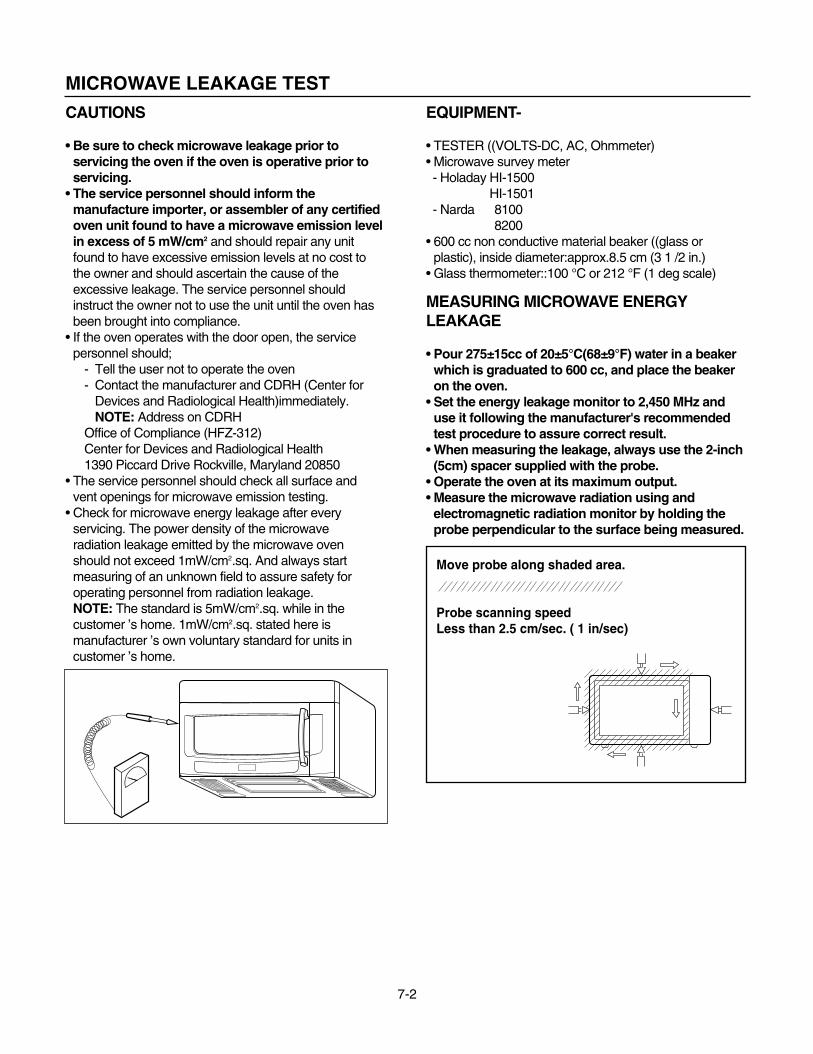
• Pour 275±15cc of 20±5°C(68±9°F) water in a beakerwhich is graduated to 600 cc, and place the beakeron the oven.
• Set the energy leakage monitor to 2,450 MHz anduse it following the manufacturer's recommendedtest procedure to assure correct result.
• When measuring the leakage, always use the 2-inch(5cm) spacer supplied with the probe.
• Operate the oven at its maximum output.• Measure the microwave radiation using and
electromagnetic radiation monitor by holding theprobe perpendicular to the surface being measured.
Move probe along shaded area.
Probe scanning speedLess than 2.5 cm/sec. ( 1 in/sec)
7-3
MEASUREMENT WITH THE OUTSIDEREMOVED(1) When you replace the magnetron, measure for
microwave energy leakage before the outer caseis installed and after all necessary componentsare replaced or adjusted. Special care should betaken in measuring the following parts.-Around the magnetron-The waveguide
WARNING: AVOID CONTACTING ANY HIGHVOLTAGE PARTS.
MEASUREMENT WITH A FULLYASSEMBLED OVEN(1) After all components, including the outer
panels, are fully assembled, measure formicrowave energy leakage around the doorviewing window, the exhaust opening and airinlet openings.
(2) Microwave energy leakage must not exceed thevalues prescribed below.NOTES:Leakage with the outer panels removed -lessthan 5 mW/cm2.Leakage for a fully assembled oven (“Before thelatch switch (primary)is interrupted ”)with the doorin a slightly opened position -less than 1 mW/cm2
NOTE WHEN MEASURING(1) Do not exceed meter full scale deflection.(2) The test probe must be removed no faster than
1 inch/sec (2.5cm/sec)along the shaded area,otherwise a false reading may result.
(3) The test probe must be held with the grip portionof the handle. A false reading may result if theoperator ’s hand is between the handle and theprobe.
(4) When testing near a corner of the door, keepthe probe perpendicular to the surface makingsure the probe is moved horizontally along theoven surface.
RECORD KEEPING AND NOTIFICATIONAFTER MEASUREMENT(1) After adjustment and repair of any microwave
energy interruption or microwave energy blockingdevice, record the measured values for futurereference. Also enter the information on theservice invoice.
(2) Should the microwave energy leakage not bemore than 1 mW/cm2 after determining that allparts are in good condition, functioning properlyand genuine replacement parts which are listed inthis manual have been used.
(3) At least once a year, have the electromagneticenergy leakage monitor checked for calibrationby its manufacturer.
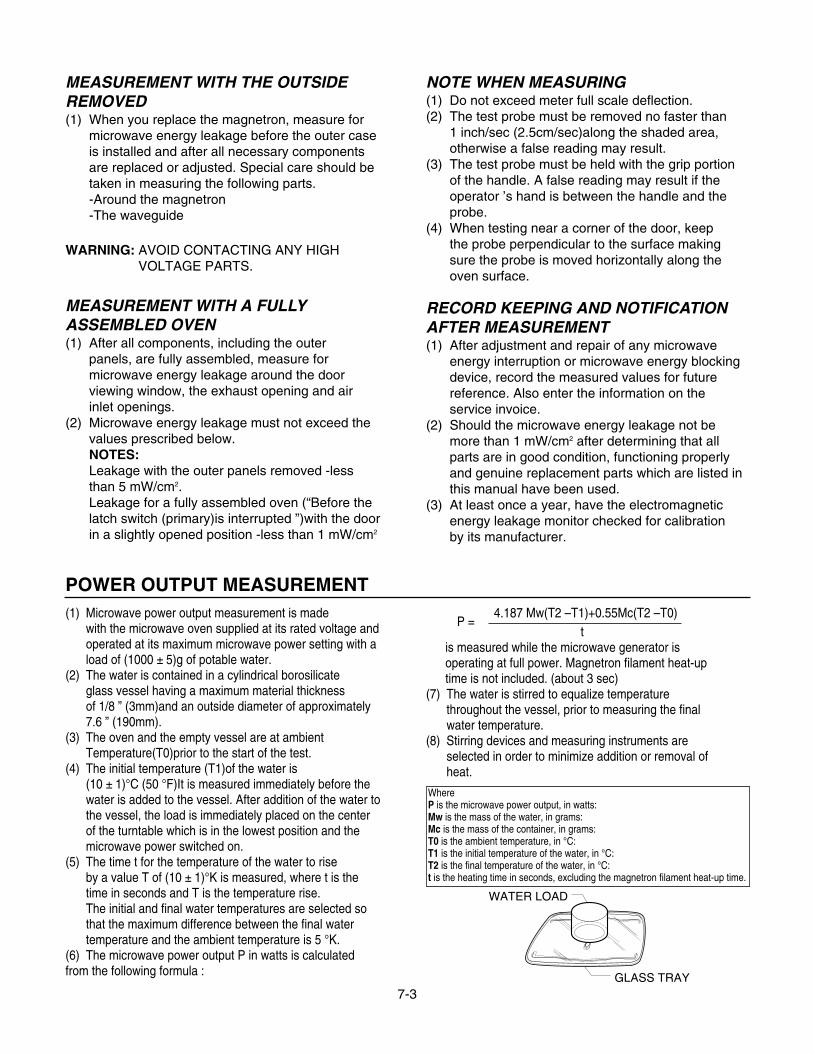
POWER OUTPUT MEASUREMENT(1) Microwave power output measurement is made
with the microwave oven supplied at its rated voltage andoperated at its maximum microwave power setting with aload of (1000 ± 5)g of potable water.
(2) The water is contained in a cylindrical borosilicateglass vessel having a maximum material thicknessof 1/8 ” (3mm)and an outside diameter of approximately7.6 ” (190mm).
(3) The oven and the empty vessel are at ambientTemperature(T0)prior to the start of the test.
(4) The initial temperature (T1)of the water is(10 ± 1)°C (50 °F)It is measured immediately before thewater is added to the vessel. After addition of the water tothe vessel, the load is immediately placed on the centerof the turntable which is in the lowest position and themicrowave power switched on.
(5) The time t for the temperature of the water to riseby a value T of (10 ± 1)°K is measured, where t is thetime in seconds and T is the temperature rise.The initial and final water temperatures are selected sothat the maximum difference between the final watertemperature and the ambient temperature is 5 °K.
(6) The microwave power output P in watts is calculatedfrom the following formula :
4.187 Mw(T2 –T1)+0.55Mc(T2 –T0)t
is measured while the microwave generator isoperating at full power. Magnetron filament heat-uptime is not included. (about 3 sec)
(7) The water is stirred to equalize temperaturethroughout the vessel, prior to measuring the finalwater temperature.
(8) Stirring devices and measuring instruments areselected in order to minimize addition or removal ofheat.
P =
WhereP is the microwave power output, in watts:Mw is the mass of the water, in grams:Mc is the mass of the container, in grams:T0 is the ambient temperature, in °C:T1 is the initial temperature of the water, in °C:T2 is the final temperature of the water, in °C:t is the heating time in seconds, excluding the magnetron filament heat-up time.
WATER LOAD
GLASS TRAY
7-4
DISASSEMBLY INSTRUCTIONS
IMPORTANT NOTES:
UNIT MUST BE DISCONNECTED FROM ELEC-TRICAL OUTLET WHEN MAKING REPAIRS, RE-PLACEMENTS, ADJUSTMENTS AND CONTIN-UITY CHECKS.WHEN RECONNECTING THE WIRE LEADS TOANY PART, MAKE SURE THE WIRING CONNE-CTIONS AND LEAD COLORS ARE CORRECTLYMATCHED ACCORDING TO THE OVERALL CIR-CUIT DIAGRAM. (ESPECIALLY SWITCHES ANDHIGH VOLTAGE CIRCUIT.)
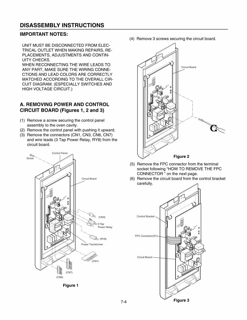
A. REMOVING POWER AND CONTROLCIRCUIT BOARD (Figures 1, 2 and 3)
(1) Remove a screw securing the control panelassembly to the oven cavity.
(2) Remove the control panel with pushing it upward.(3) Remove the connectors (CN1, CN3, CN6, CN7)
and wire leads (3 Tap Power Relay, RY8) from thecircuit board.
(4) Remove 3 screws securing the circuit board.
Power Transformer
Control Panel
Screw
Circuit Board
(CN3)
(RY8)
3 Tap Power Relay
(CN1)
(CN7)
(CN6)
Circuit Board
Control Bracket
Circuit Board
FPC Connector(S1)
(5) Remove the FPC connector from the terminalsocket following “HOW TO REMOVE THE FPCCONNECTOR ” on the next page.
(6) Remove the circuit board from the control bracketcarefully.
Figure 1
Figure 2
Figure 3
7-5
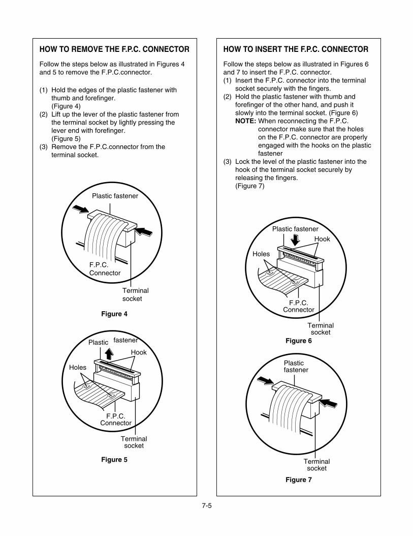
HOW TO REMOVE THE F.P.C. CONNECTOR
Follow the steps below as illustrated in Figures 4and 5 to remove the F.P.C.connector.
(1) Hold the edges of the plastic fastener withthumb and forefinger.(Figure 4)
(2) Lift up the lever of the plastic fastener fromthe terminal socket by lightly pressing thelever end with forefinger.(Figure 5)
(3) Remove the F.P.C.connector from theterminal socket.
HOW TO INSERT THE F.P.C. CONNECTOR
Follow the steps below as illustrated in Figures 6and 7 to insert the F.P.C. connector.(1) Insert the F.P.C. connector into the terminal
socket securely with the fingers.(2) Hold the plastic fastener with thumb and
forefinger of the other hand, and push itslowly into the terminal socket. (Figure 6)NOTE: When reconnecting the F.P.C.
connector make sure that the holeson the F.P.C. connector are properlyengaged with the hooks on the plasticfastener
(3) Lock the level of the plastic fastener into thehook of the terminal socket securely byreleasing the fingers.(Figure 7)
Figure 4
Figure 6
Figure 7
Figure 5
F.P.C.Connector
Terminalsocket
Plastic fastener
Holes
Hook
Plastic fastener
Terminalsocket
F.P.C.Connector
Plasticfastener
Terminalsocket
F.P.C.Connector
Terminalsocket
Plastic fastener
Holes
Hook
7-6
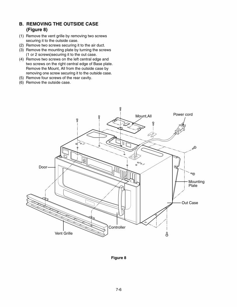
B. REMOVING THE OUTSIDE CASE(Figure 8)
(1) Remove the vent grille by removing two screwssecuring it to the outside case.
(2) Remove two screws securing it to the air duct.(3) Remove the mounting plate by turning the screws
(1 or 2 screws)securing it to the out case.(4) Remove two screws on the left central edge and
two screws on the right central edge of Base plate.Remove the Mount, All from the outside case byremoving one screw securing it to the outside case.
(5) Remove four screws of the rear cavity.(6) Remove the outside case.
Mount,All
Vent Grille
Out Case
MountingPlate
Power cord
Door
Controller
Figure 8
7-7
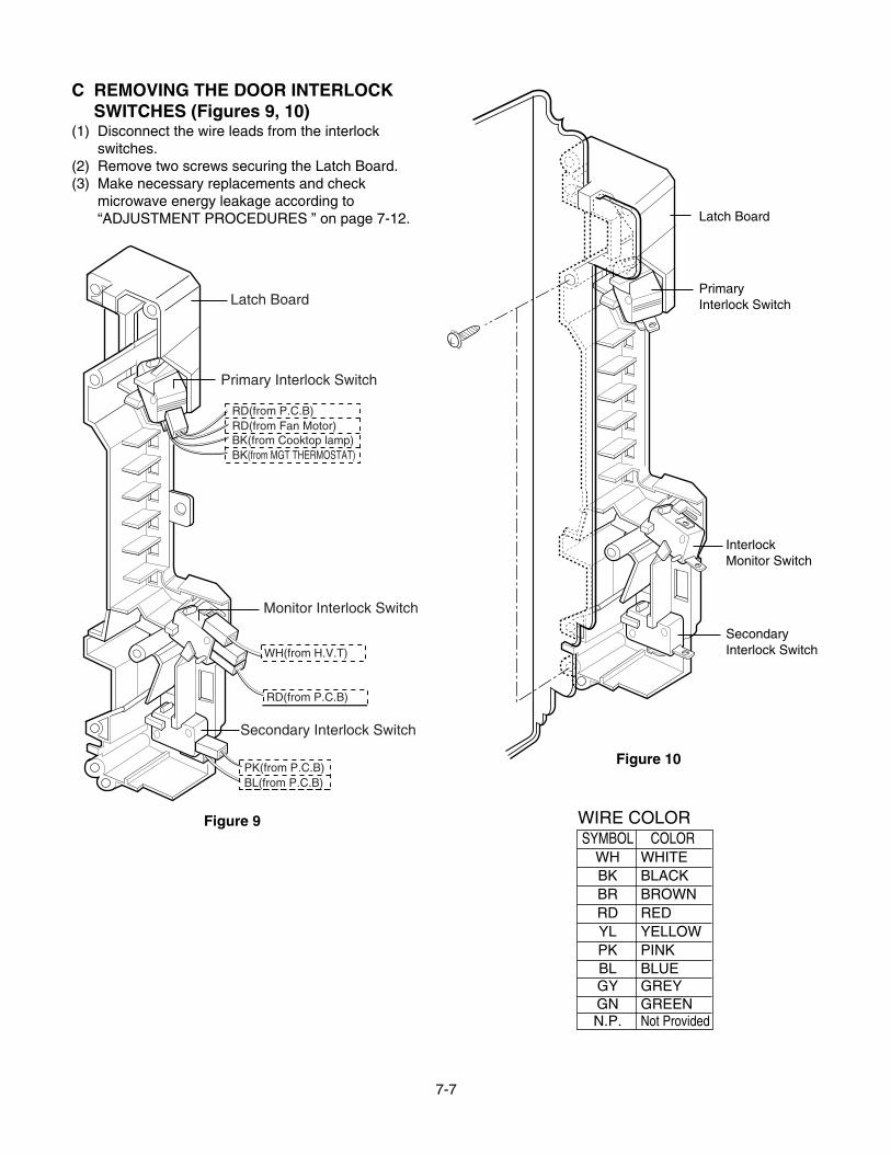
C REMOVING THE DOOR INTERLOCKSWITCHES (Figures 9, 10)
(1) Disconnect the wire leads from the interlockswitches.
(2) Remove two screws securing the Latch Board.(3) Make necessary replacements and check
microwave energy leakage according to“ADJUSTMENT PROCEDURES ” on page 7-12.
Latch Board
Primary Interlock Switch
RD(from P.C.B)RD(from Fan Motor)BK(from Cooktop lamp)
WH(from H.V.T)
PK(from P.C.B)BL(from P.C.B)
RD(from P.C.B)
BK(from MGT THERMOSTAT)
Monitor Interlock Switch
Secondary Interlock Switch
Latch Board
PrimaryInterlock Switch
InterlockMonitor Switch
SecondaryInterlock Switch
Figure 9
Figure 10
WIRE COLORSYMBOL COLOR
WH WHITEBK BLACKBR BROWNRD REDYL YELLOWPK PINKBL BLUEGY GREYGN GREENN.P. Not Provided
7-8
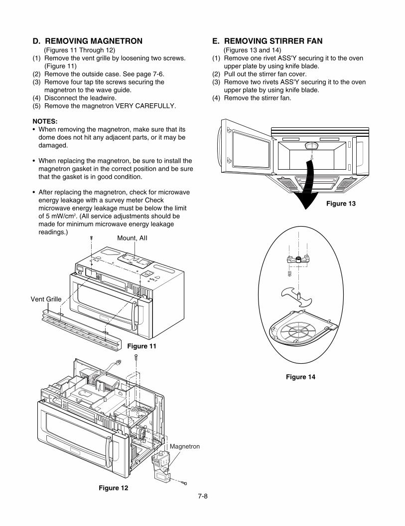
D. REMOVING MAGNETRON(Figures 11 Through 12)
(1) Remove the vent grille by loosening two screws.(Figure 11)
(2) Remove the outside case. See page 7-6.(3) Remove four tap tite screws securing the
magnetron to the wave guide.(4) Disconnect the leadwire.(5) Remove the magnetron VERY CAREFULLY.
NOTES:• When removing the magnetron, make sure that its
dome does not hit any adjacent parts, or it may bedamaged.
• When replacing the magnetron, be sure to install themagnetron gasket in the correct position and be surethat the gasket is in good condition.
• After replacing the magnetron, check for microwaveenergy leakage with a survey meter Checkmicrowave energy leakage must be below the limitof 5 mW/cm2. (All service adjustments should bemade for minimum microwave energy leakagereadings.)
E. REMOVING STIRRER FAN(Figures 13 and 14)
(1) Remove one rivet ASS'Y securing it to the ovenupper plate by using knife blade.
(2) Pull out the stirrer fan cover.(3) Remove two rivets ASS'Y securing it to the oven
upper plate by using knife blade.(4) Remove the stirrer fan.
Mount, AII
Vent Grille
Magnetron
Figure 12
Figure 11
Figure 13
Figure 14
7-9
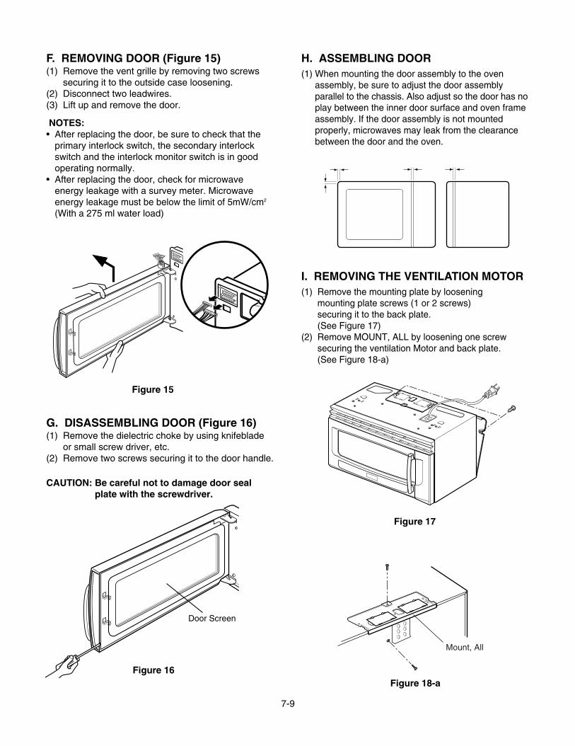
F. REMOVING DOOR (Figure 15)(1) Remove the vent grille by removing two screws
securing it to the outside case loosening.(2) Disconnect two leadwires.(3) Lift up and remove the door.
NOTES:• After replacing the door, be sure to check that the
primary interlock switch, the secondary interlockswitch and the interlock monitor switch is in goodoperating normally.
• After replacing the door, check for microwaveenergy leakage with a survey meter. Microwaveenergy leakage must be below the limit of 5mW/cm2
(With a 275 ml water load)
G. DISASSEMBLING DOOR (Figure 16)(1) Remove the dielectric choke by using knifeblade
or small screw driver, etc.(2) Remove two screws securing it to the door handle.
CAUTION: Be careful not to damage door sealplate with the screwdriver.
H. ASSEMBLING DOOR(1) When mounting the door assembly to the oven
assembly, be sure to adjust the door assemblyparallel to the chassis. Also adjust so the door has noplay between the inner door surface and oven frameassembly. If the door assembly is not mountedproperly, microwaves may leak from the clearancebetween the door and the oven.
I. REMOVING THE VENTILATION MOTOR(1) Remove the mounting plate by loosening
mounting plate screws (1 or 2 screws)securing it to the back plate.(See Figure 17)
(2) Remove MOUNT, ALL by loosening one screwsecuring the ventilation Motor and back plate.(See Figure 18-a)
Figure 15
Door Screen
Figure 16
Figure 17
Figure 18-a
Mount, All
7-10
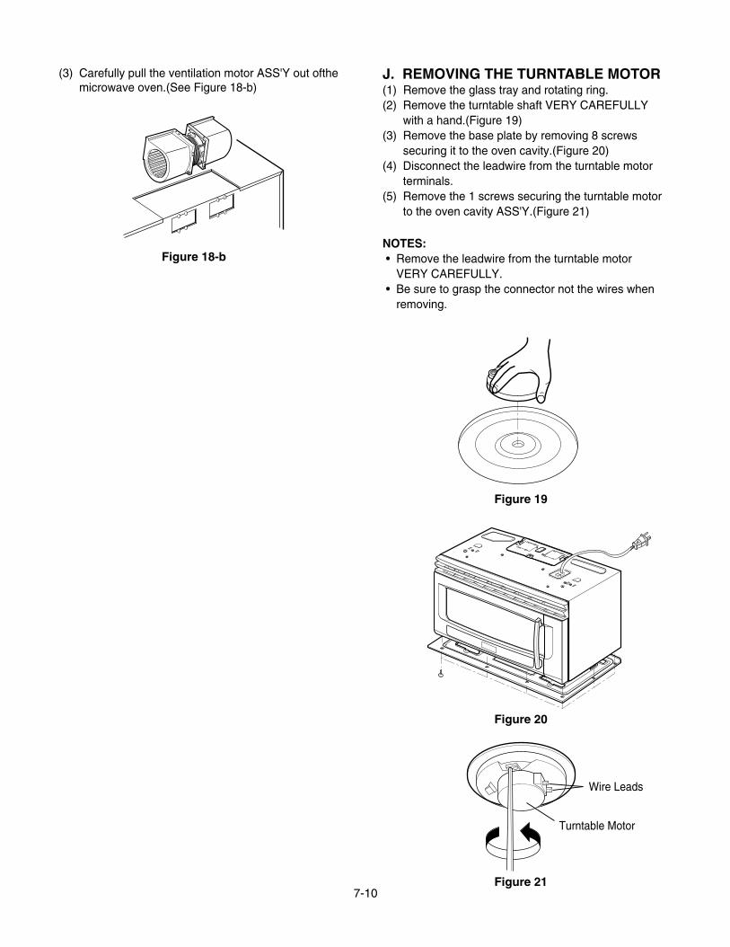
(3) Carefully pull the ventilation motor ASS'Y out ofthemicrowave oven.(See Figure 18-b)
J. REMOVING THE TURNTABLE MOTOR(1) Remove the glass tray and rotating ring.(2) Remove the turntable shaft VERY CAREFULLY
with a hand.(Figure 19)(3) Remove the base plate by removing 8 screws
securing it to the oven cavity.(Figure 20)(4) Disconnect the leadwire from the turntable motor
terminals.(5) Remove the 1 screws securing the turntable motor
to the oven cavity ASS'Y.(Figure 21)
NOTES:• Remove the leadwire from the turntable motor
VERY CAREFULLY.• Be sure to grasp the connector not the wires when
removing.
Figure 18-b
Figure 19
Figure 20
Figure 21
Wire Leads
Turntable Motor
7-11
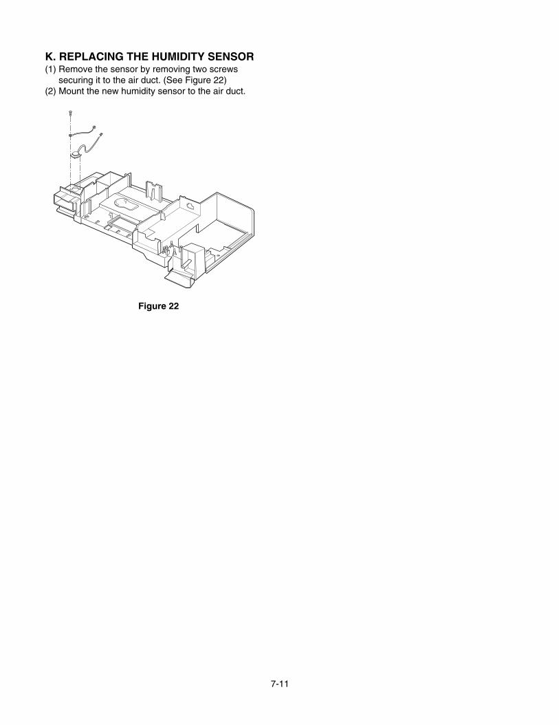
K. REPLACING THE HUMIDITY SENSOR(1) Remove the sensor by removing two screws
securing it to the air duct. (See Figure 22)(2) Mount the new humidity sensor to the air duct.
Figure 22
7-12
INTERLOCK MECHANISMThe door lock mechanism is a device which has been specially designed to eliminate microwave activity when thedoor is opened during cooking and thus to prevent the danger resulting from the microwave leakage.
ADJUSTMENT PROCEDURESTo avoid possible exposure to microwave energy
leakage, adjust the door latches and interlockswitches, using the following procedure.
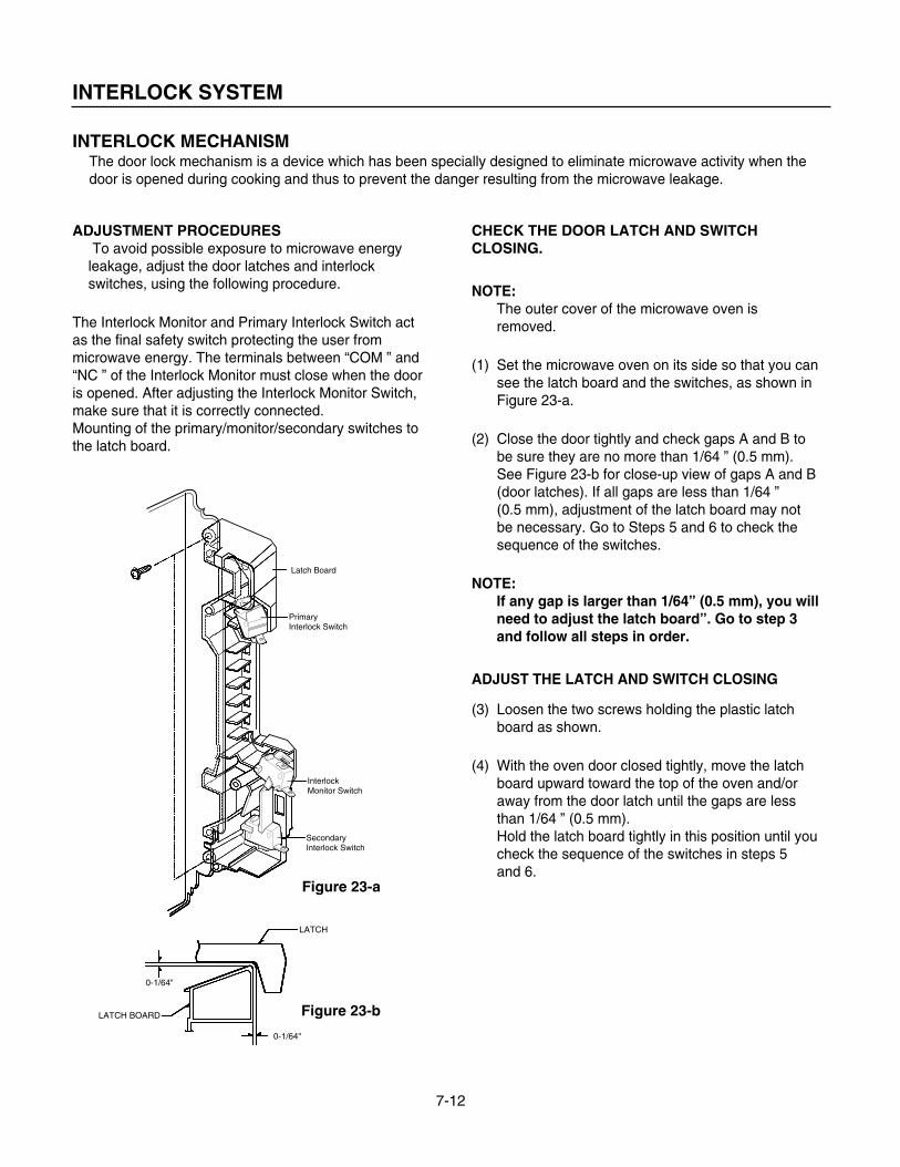
The Interlock Monitor and Primary Interlock Switch actas the final safety switch protecting the user frommicrowave energy. The terminals between “COM ” and“NC ” of the Interlock Monitor must close when the dooris opened. After adjusting the Interlock Monitor Switch, make sure that it is correctly connected.Mounting of the primary/monitor/secondary switches tothe latch board.
CHECK THE DOOR LATCH AND SWITCHCLOSING.
NOTE:The outer cover of the microwave oven isremoved.
(1) Set the microwave oven on its side so that you cansee the latch board and the switches, as shown inFigure 23-a.
(2) Close the door tightly and check gaps A and B tobe sure they are no more than 1/64 ” (0.5 mm).See Figure 23-b for close-up view of gaps A and B(door latches). If all gaps are less than 1/64 ”(0.5 mm), adjustment of the latch board may notbe necessary. Go to Steps 5 and 6 to check thesequence of the switches.
NOTE:If any gap is larger than 1/64” (0.5 mm), you willneed to adjust the latch board”. Go to step 3and follow all steps in order.
ADJUST THE LATCH AND SWITCH CLOSING
(3) Loosen the two screws holding the plastic latchboard as shown.
(4) With the oven door closed tightly, move the latchboard upward toward the top of the oven and/oraway from the door latch until the gaps are lessthan 1/64 ” (0.5 mm).Hold the latch board tightly in this position until youcheck the sequence of the switches in steps 5and 6.
INTERLOCK SYSTEM
InterlockMonitor Switch
LATCH
LATCH BOARD
0-1/64"
0-1/64"
Latch Board
PrimaryInterlock Switch
SecondaryInterlock Switch
Figure 23-a
Figure 23-b
7-13
TEST THE LATCH AND SWITCH SEQUENCE
(5) Open the oven door slowly. Watch the door latch,the Secondary Switch. Release Rod and Leveron the switches to make sure they are zero to thebody of the switches in the following sequence:
-Primary Interlock Switch-Secondary Interlock Switch-Interlock Monitor Switch
Adjust the latch board until the switches operate inthis sequence. See Steps 3 and 4.
(6) Close the oven door slowly and be sure it is tightlyclosed. Watch the three switches to make surethey are zero to the body of the switches in thefollowing sequence:
-Interlock Monitor Switch-Primary Interlock Switch-Secondary Interlock Switch
NOTE: The Interlock Monitor Switch is an addedsafety check on the Primary andSecondary Interlock Switches. If thePrimary and Secondary Interlock Switchesallow the oven to operate with the dooropen, the Monitor Switch will blow thefuse.
(7) When you achieve the proper sequence ofswitches in Steps 5 and 6, tighten the latch boardscrews at that point.
TEST THE MICROWAVE ENERGY LEAKAGE
Make sure the microwave energy leakage is below thelimit of 1mW/cm2 (with a 275 ml water load)and5mW/cm2 (with a 275 ml water load without thecabinet)when measured with a survey meter.
7-14
A. PRIMARY INTERLOCK SWITCH TEST
When the door is opened slowly, an audible clickshould be heard at the same time or successivelyat intervals and the latches should activate theswitches with an audible clickIf the latches do not activate the switches when thedoor is closed, the switches should be a adjustedin accordance with the adjustment procedure.Disconnect the wire lead from the primary switch.Connect the ohmmeter leads to the common(COM)and normally open (NO)terminal of theswitch. The meter should indicate an open circuitin the door open condition.When the door is closed, the meter should indicatea closed circuit.When the primary switch operation is abnormal,make the necessary adjustment or replace theswitch only with the same type of switch.
B. SECONDARY INTERLOCK SWITCH TEST
Disconnect the wire lead from the secondaryswitch.Connect the ohmmeter leads to the common(COM)and normally open (NO)terminals of theswitch. The meter should indicate a open circuit inthe door open condition. When the door is closed,meter should indicate an closed circuit. When thesecondary switch operation is abnormal, make thenecessary adjustment or replace the switch onlywith the same type of switch.
C. MONITOR SWITCH TESTDisconnect the wire lead from the monitor switch.Connect the ohmmeter leads to the common(COM)and normally closed (NC)terminals of theswitch. The meter should indicate closed circuit inthe door open condition. When the door is closed,meter should indicate an open circuit. When themonitor switch operation is abnormal, replace withthe same type of switch.NOTE: After repairing the door or the interlocksystem, it is necessary to do this continuitytest before operating the oven.
INTERLOCK CONTINUITY TEST
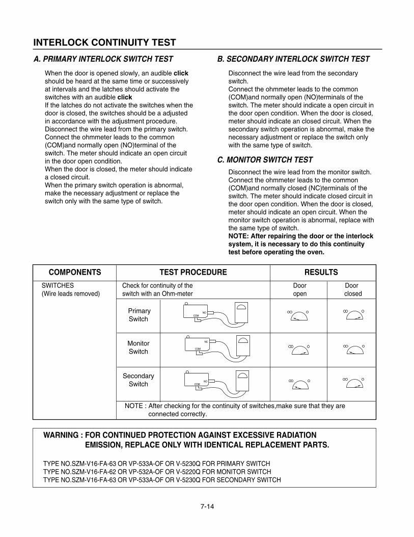
COMPONENTS TEST PROCEDURE RESULTS
SWITCHES Check for continuity of the Door Door(Wire leads removed) switch with an Ohm-meter open closed
PrimarySwitch
MonitorSwitch
SecondarySwitch
NOTE : After checking for the continuity of switches,make sure that they areconnected correctly.
WARNING : FOR CONTINUED PROTECTION AGAINST EXCESSIVE RADIATIONEMISSION, REPLACE ONLY WITH IDENTICAL REPLACEMENT PARTS.
TYPE NO.SZM-V16-FA-63 OR VP-533A-OF OR V-5230Q FOR PRIMARY SWITCHTYPE NO.SZM-V16-FA-62 OR VP-532A-OF OR V-5220Q FOR MONITOR SWITCHTYPE NO.SZM-V16-FA-63 OR VP-533A-OF OR V-5230Q FOR SECONDARY SWITCH
NOCOM
NC
COM
NOCOM
7-15
TEST AND CHECKOUT PRECEDURES AND TROUBLESHOOTING
CAUTIONS1. DISCONNECT THE POWER SUPPLY CORD FROM THE OUTLET WHENEVER REMOVING THE OUTER CASE
FROM THE UNIT. PROCEED WITH THE TEST ONLY AFTER DISCHARGING THE HIGH VOLTAGE CAPACITORAND REMOVING THE LEAD WIRES FROM THE PRIMARY WINDING OF THE HIGH VOLTAGE TRANSFORMER.
2. ALL OPERATIONAL CHECKS WITH MICROWAVE ENERGY MUST BE DONE WITH A LOAD (1 LITER OFWATER IN CONTAINER)IN THE OVEN.
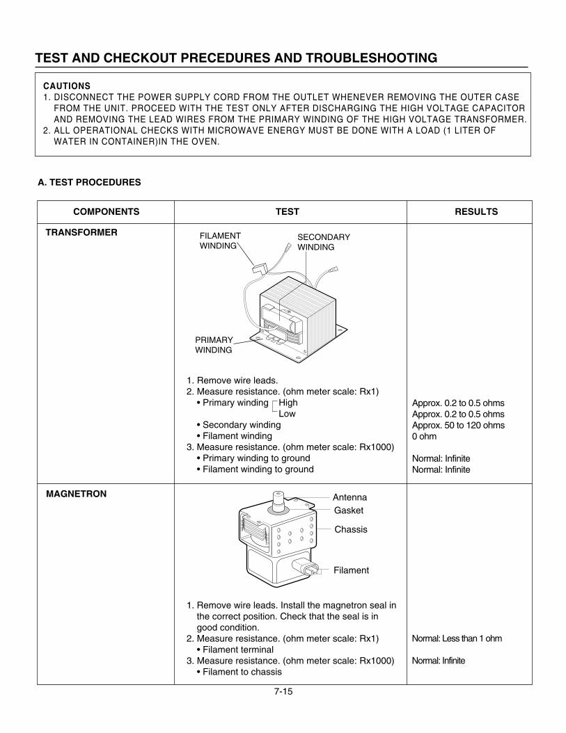
A. TEST PROCEDURES
TRANSFORMER
MAGNETRON
1. Remove wire leads.2. Measure resistance. (ohm meter scale: Rx1)
• Primary winding HighLow
• Secondary winding• Filament winding
3. Measure resistance. (ohm meter scale: Rx1000)• Primary winding to ground• Filament winding to ground
1. Remove wire leads. Install the magnetron seal inthe correct position. Check that the seal is ingood condition.
2. Measure resistance. (ohm meter scale: Rx1)• Filament terminal
3. Measure resistance. (ohm meter scale: Rx1000)• Filament to chassis
Normal: Less than 1 ohm
Normal: Infinite
COMPONENTS TEST RESULTS
SECONDARYWINDING
PRIMARYWINDING
FILAMENTWINDING
Approx. 0.2 to 0.5 ohms Approx. 0.2 to 0.5 ohms Approx. 50 to 120 ohms 0 ohm
Normal: Infinite Normal: Infinite
Filament
AntennaGasket
Chassis
7-16
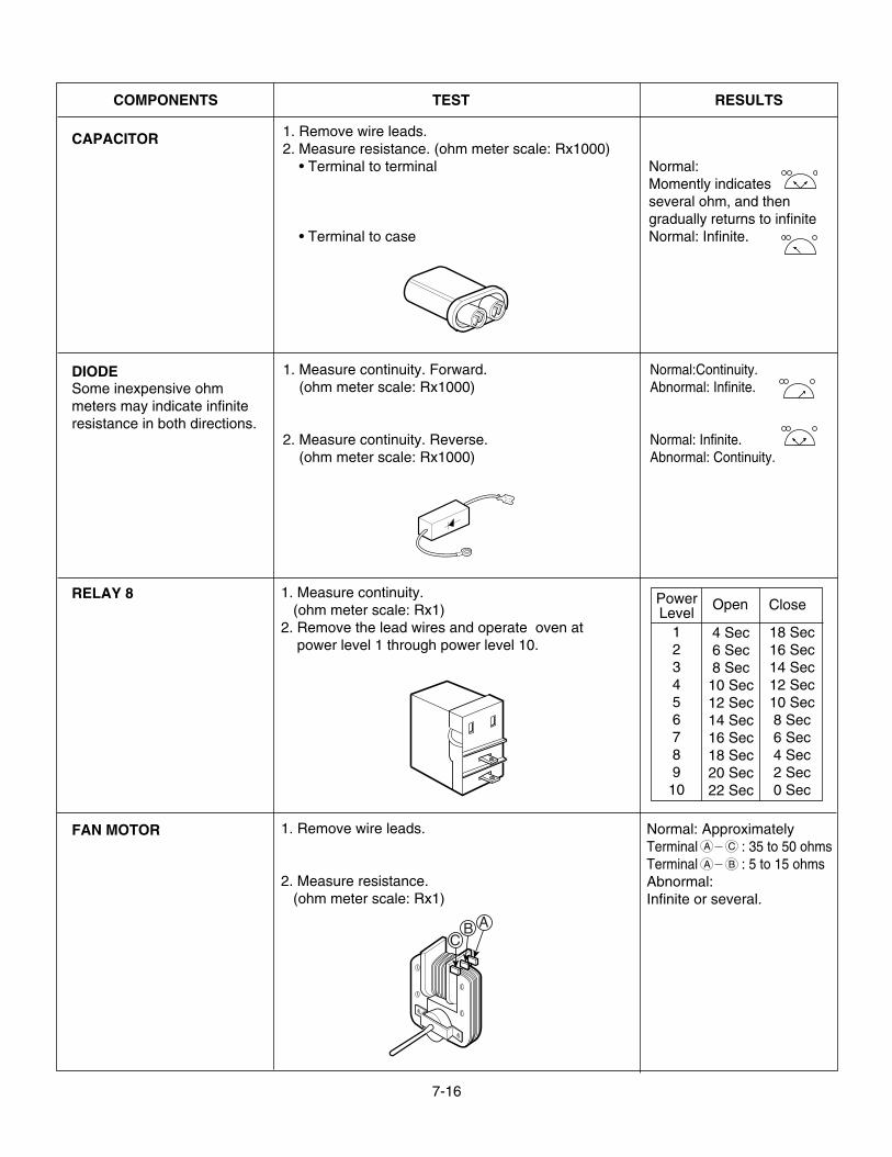
COMPONENTS TEST RESULTS
Normal:Momently indicatesseveral ohm, and thengradually returns to infiniteNormal: Infinite.
Normal:Continuity.Abnormal: Infinite.
Normal: Infinite.Abnormal: Continuity.
1. Remove wire leads.2. Measure resistance. (ohm meter scale: Rx1000)
• Terminal to terminal
• Terminal to case
1. Measure continuity. Forward.(ohm meter scale: Rx1000)
2. Measure continuity. Reverse.(ohm meter scale: Rx1000)
CAPACITOR
DIODESome inexpensive ohmmeters may indicate infiniteresistance in both directions.
1. Measure continuity.(ohm meter scale: Rx1)
2. Remove the lead wires and operate oven atpower level 1 through power level 10.
RELAY 8
1. Remove wire leads.
2. Measure resistance.(ohm meter scale: Rx1)
Normal: ApproximatelyTerminal : 35 to 50 ohmsTerminal : 5 to 15 ohmsAbnormal:Infinite or several.
ABC
FAN MOTORA C
A B
PowerLevel
Open Close
12345678910
4 Sec6 Sec8 Sec10 Sec12 Sec14 Sec16 Sec18 Sec20 Sec22 Sec
18 Sec16 Sec14 Sec12 Sec10 Sec8 Sec6 Sec4 Sec2 Sec0 Sec
7-17
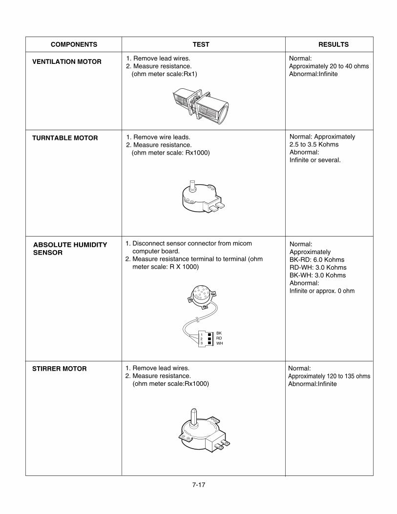
COMPONENTS TEST RESULTS
Normal:Approximately 20 to 40 ohmsAbnormal:Infinite
Normal: Approximately2.5 to 3.5 KohmsAbnormal:Infinite or several.
Normal:ApproximatelyBK-RD: 6.0 KohmsRD-WH: 3.0 KohmsBK-WH: 3.0 KohmsAbnormal:Infinite or approx. 0 ohm
1. Remove lead wires.2. Measure resistance.
(ohm meter scale:Rx1)
1. Remove wire leads.2. Measure resistance.
(ohm meter scale: Rx1000)
VENTILATION MOTOR
TURNTABLE MOTOR
1. Disconnect sensor connector from micomcomputer board.
2. Measure resistance terminal to terminal (ohmmeter scale: R X 1000)
RDBK
WH
123
ABSOLUTE HUMIDITYSENSOR
1. Remove lead wires.2. Measure resistance.
(ohm meter scale:Rx1000)
Normal:Approximately 120 to 135 ohmsAbnormal:Infinite
STIRRER MOTOR
7-18
COMPONENTS TEST RESULTS
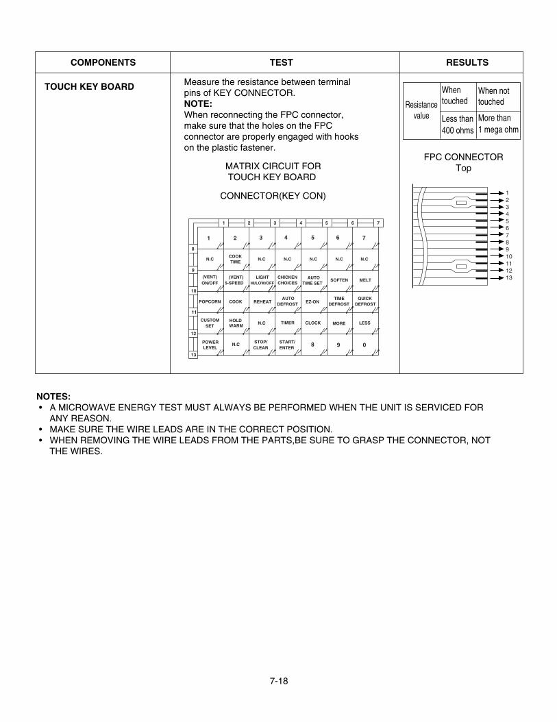
Measure the resistance between terminalpins of KEY CONNECTOR.NOTE:When reconnecting the FPC connector,make sure that the holes on the FPCconnector are properly engaged with hookson the plastic fastener.
MATRIX CIRCUIT FORTOUCH KEY BOARD
CONNECTOR(KEY CON)
TOUCH KEY BOARD
Resistancevalue
Whentouched
Less than400 ohms
When nottouched
More than1 mega ohm
FPC CONNECTORTop
1 2345678910111213
NOTES:• A MICROWAVE ENERGY TEST MUST ALWAYS BE PERFORMED WHEN THE UNIT IS SERVICED FOR
ANY REASON.• MAKE SURE THE WIRE LEADS ARE IN THE CORRECT POSITION.• WHEN REMOVING THE WIRE LEADS FROM THE PARTS,BE SURE TO GRASP THE CONNECTOR, NOT
THE WIRES.
N.C
SOFTEN
MORE
DEFROSTTIME
CUSTOM HOLD
LEVELPOWER
SET
N.C
WARM
ON/OFF(VENT)
POPCORN COOK
5-SPEED
N.C
(VENT)
TIMECOOK
CLOCK
CLEARSTOP/
N.C
START/ENTER
TIMER
8 9
CHOICESCHICKEN
DEFROST
HI/LOW/OFF
REHEATAUTO
LIGHT
N.C N.C
TIME SETAUTO
N.C
1 2 3 4 5 6
LESS
0
DEFROSTQUICK
N.C
MELT
7
EZ-ON
8
13
12
11
10
9
1 2 3 4 5 6 7
7-19
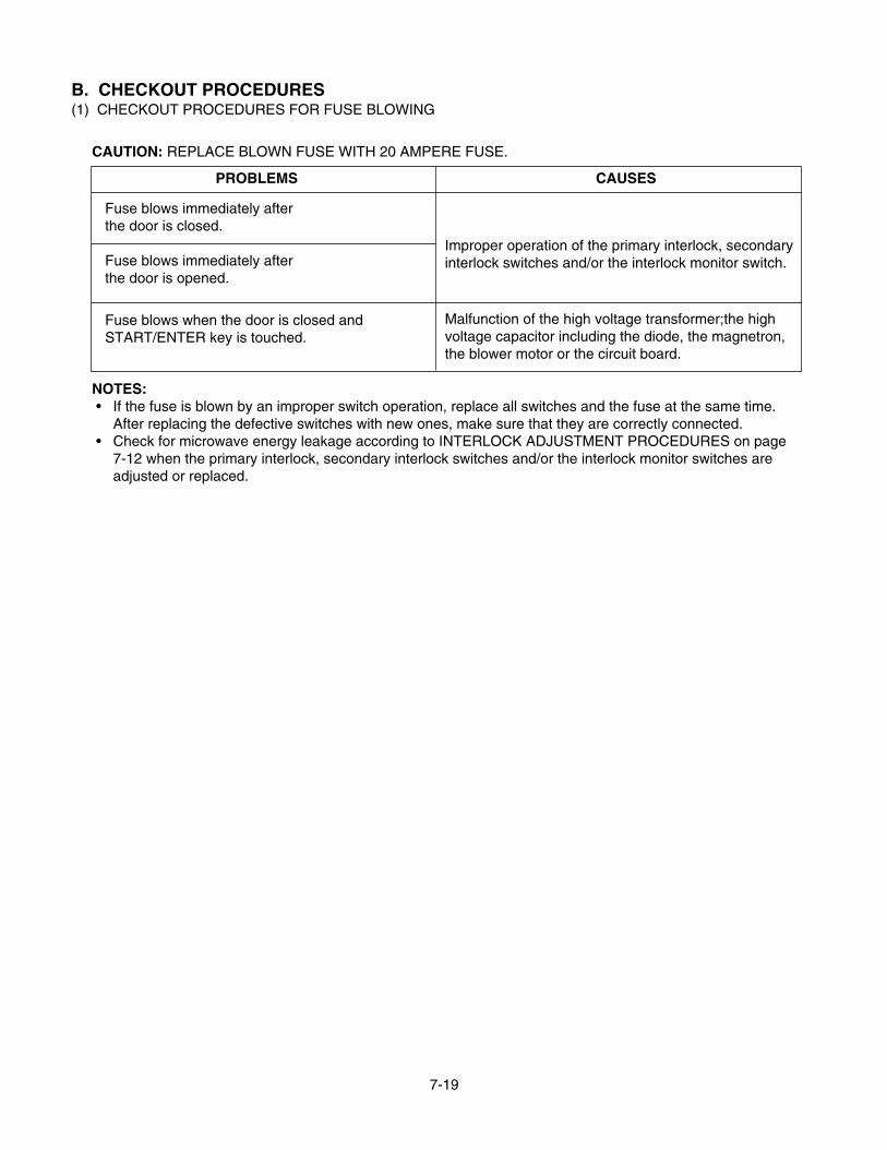
B. CHECKOUT PROCEDURES(1) CHECKOUT PROCEDURES FOR FUSE BLOWING
CAUTION: REPLACE BLOWN FUSE WITH 20 AMPERE FUSE.
NOTES:• If the fuse is blown by an improper switch operation, replace all switches and the fuse at the same time.
After replacing the defective switches with new ones, make sure that they are correctly connected.• Check for microwave energy leakage according to INTERLOCK ADJUSTMENT PROCEDURES on page
7-12 when the primary interlock, secondary interlock switches and/or the interlock monitor switches areadjusted or replaced.
Fuse blows immediately afterthe door is closed.
Fuse blows immediately afterthe door is opened.
Fuse blows when the door is closed andSTART/ENTER key is touched.
Improper operation of the primary interlock, secondaryinterlock switches and/or the interlock monitor switch.
Malfunction of the high voltage transformer;the highvoltage capacitor including the diode, the magnetron,the blower motor or the circuit board.
PROBLEMS CAUSES
7-20
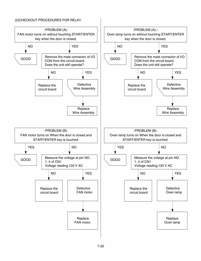
(2)CHECKOUT PROCEDURES FOR RELAY.
-PROBLEM (A)-FAN motor turns on without touching START/ENTER
key when the door is closed.
-PROBLEM (B)-FAN motor turns on When the door is closed and
START/ENTER key is touched.
GOODRemove the mate connector of I/OCON from the circuit board.Does the unit still operate?
DefectiveWire Assembly
Replace thecircuit board
ReplaceWire Assembly
NO
NO
YES
YES
-PROBLEM (A)--Oven lamp turns on without touching START/ENTER
key when the door is closed.
GOODRemove the mate connector of I/OCON from the circuit board.Does the unit still operate?
DefectiveWire Assembly
Replace thecircuit board
ReplaceWire Assembly
NO
NO
YES
YES
GOODMeasure the voltage at pin NO.1, 4 of CN1Voltage reading:120 V AC
Replace thecircuit board
DefectiveFAN motor
YES
NO
NO
YES
ReplaceFAN motor.
-PROBLEM (B)-Oven lamp turns on When the door is closed and
START/ENTER key is touched.
GOODMeasure the voltage at pin NO.1, 4 of CN1Voltage reading:120 V AC
Replace thecircuit board
DefectiveOven lamp
YES
NO
NO
YES
ReplaceOven lamp
7-21
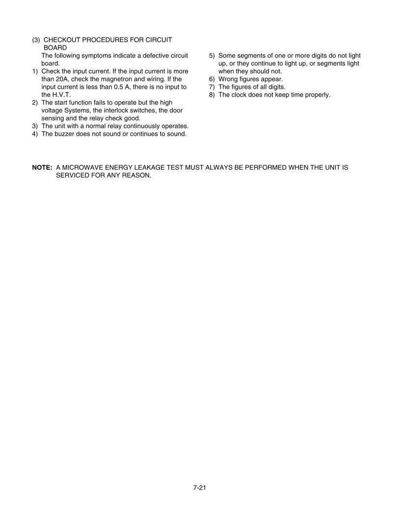
(3) CHECKOUT PROCEDURES FOR CIRCUITBOARD
The following symptoms indicate a defective circuitboard.
1) Check the input current. If the input current is morethan 20A, check the magnetron and wiring. If theinput current is less than 0.5 A, there is no input tothe H.V.T.
2) The start function fails to operate but the highvoltage Systems, the interlock switches, the doorsensing and the relay check good.
3) The unit with a normal relay continuously operates.4) The buzzer does not sound or continues to sound.
5) Some segments of one or more digits do not lightup, or they continue to light up, or segments lightwhen they should not.
6) Wrong figures appear.7) The figures of all digits.8) The clock does not keep time properly.
NOTE: A MICROWAVE ENERGY LEAKAGE TEST MUST ALWAYS BE PERFORMED WHEN THE UNIT ISSERVICED FOR ANY REASON.
7-22
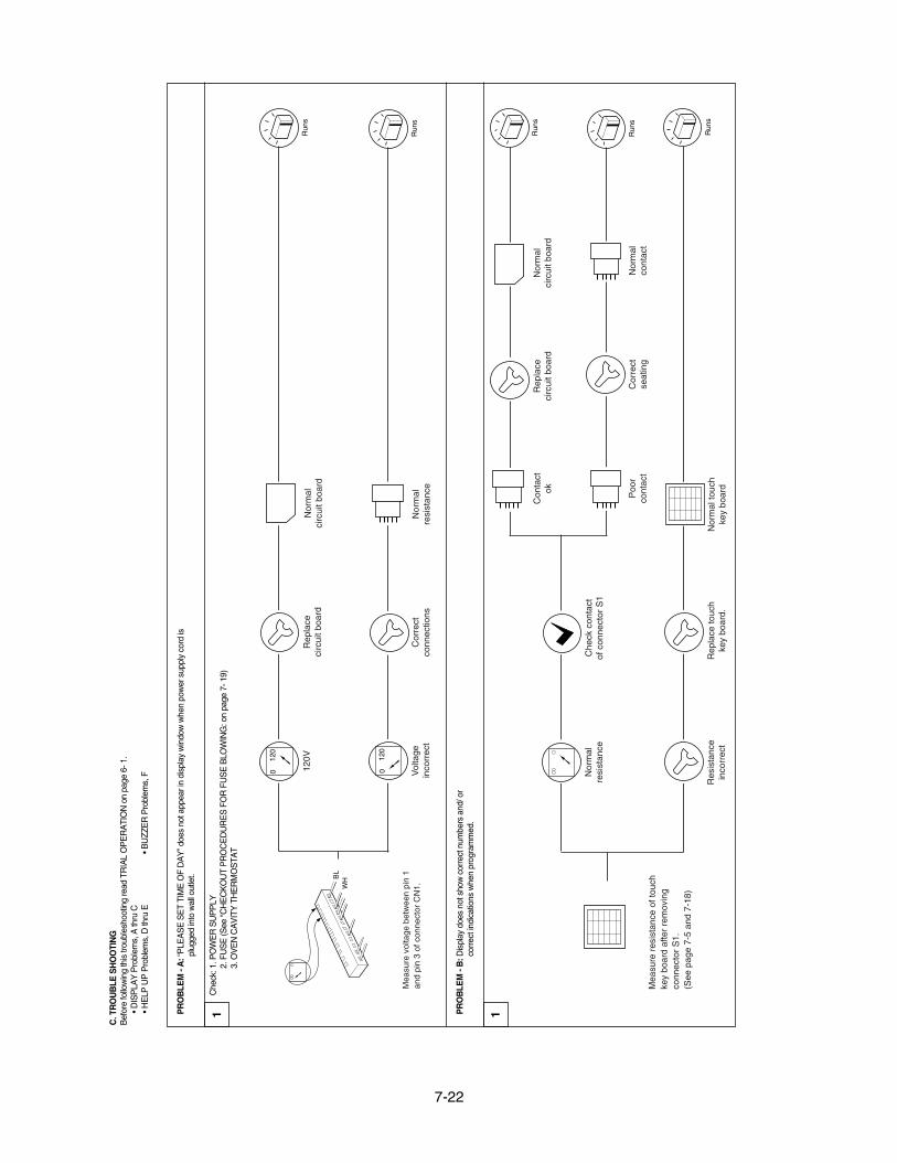
C. T
RO
UB
LE S
HO
OTI
NG
Bef
ore
follo
win
g th
is tr
oubl
esho
otin
g re
ad T
RIA
L O
PE
RA
TIO
N o
n pa
ge 6
- 1.
• DIS
PLA
Y P
robl
ems,
A th
ru C
• HE
LP U
P P
robl
ems,
D th
ru E
• BU
ZZE
R P
robl
ems,
F
PR
OB
LEM
- A
: “P
LEA
SE
SE
T TI
ME
OF
DA
Y” d
oes
not a
ppea
r in
disp
lay
win
dow
whe
n po
wer
sup
ply
cord
ispl
ugge
d in
to w
all o
utle
t.
PR
OB
LEM
- B
: Dis
play
doe
s no
t sho
w c
orre
ct n
umbe
rs a
nd/ o
rco
rrec
t ind
icat
ions
whe
n pr
ogra
mm
ed.
Che
ck: 1
. PO
WE
R S
UP
PLY
2. F
US
E (S
ee “C
HE
CK
OU
T P
RO
CE
DU
RE
S F
OR
FU
SE
BLO
WIN
G: o
n pa
ge 7
- 19)
3. O
VE
N C
AV
ITY
TH
ER
MO
STA
T
1 1
Mea
sure
vol
tage
bet
wee
n pi
n 1
and
pin
3 of
con
nect
or C
N1.
BL
WH
Run
s
Run
s
012
0
012
0
120V
Rep
lace
circ
uit b
oard
Nor
mal
circ
uit b
oard
Nor
mal
resi
stan
ceV
olta
gein
corr
ect
Cor
rect
conn
ectio
ns
Run
s
Run
s
Run
s
Mea
sure
res
ista
nce
of to
uch
key
boar
d af
ter
rem
ovin
gco
nnec
tor
S1.
(See
pag
e 7-
5 an
d 7-
18)
Nor
mal
resi
stan
ce
Res
ista
nce
inco
rrec
tR
epla
ce to
uch
key
boar
d.N
orm
al to
uch
key
boar
d
Poo
rco
ntac
tC
orre
ctse
atin
g
Con
tact
okR
epla
ceci
rcui
t boa
rdN
orm
alci
rcui
t boa
rd
Nor
mal
co
ntac
t
Che
ck c
onta
ctof
con
nect
or S
1
7-23
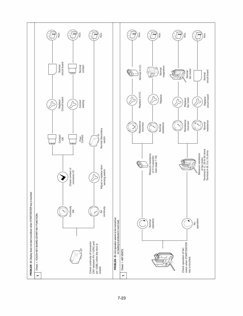
PR
OB
LEM
- E
: Dis
play
doe
s no
t sta
rt co
untd
own
whe
n S
TAR
T/E
NTE
R k
ey is
touc
hed.
Che
ck: 1
. TO
UC
H K
EY
BO
AR
D (S
TAR
T K
EY
FU
NC
TIO
N)
Che
ck: 1
. AIR
VE
NTS
PR
OB
LEM
- D
: Uni
t ope
ratio
n se
ems
to b
e no
rmal
but
no h
eatin
g is
pro
duce
d in
ove
n lo
ad.
1 1
Che
ck c
ontin
uity
of c
onne
ctor
CN
1 be
twee
n P
in 1
1(P
K)
and
pin
12(B
L) w
hen
the
door
iscl
osed
Con
tinui
tyO
KC
heck
con
tact
of
conn
ecto
r S
1
Con
tact
OK
Rep
lace
C
ircui
t boa
rd
Cor
rect
Cor
rect
seat
ing
Nor
mal
circ
uit b
oard
Nor
mal
cont
act
Poo
r
Nor
mal
Sec
onda
rysw
itch
No
cont
inui
tyA
djus
t or
repl
ace
door
sens
ing
switc
h.
Run
s
Run
s
Run
s
Che
ck o
pera
tion
of fa
nm
otor
whe
n S
TAR
T/E
NT
ER
key
is to
uche
d.
Mea
sure
res
ista
nce
of H
.V.c
apac
itor
(see
pag
e 7-
16)
Res
ista
nce
inco
rrec
t
Mea
sure
res
ista
nce
of fa
n m
otor
Term
inal
A~
C: 3
5 to
50
ohm
sTe
rmin
al A
~B
: 5 to
15
ohm
s
Res
ista
nce
inco
rrec
tR
epla
ce
fan
mot
or
Nor
mal
ci
rcui
t boa
rdR
epla
ce
Nor
mal
fan
mot
or
circ
uit b
oard
Nor
mal
resi
stan
ce
Rep
lace
H.V
.C.
Nor
mal
H.V
.C.
Nor
mal
mag
netr
onR
epla
ce
Nor
mal
oper
atio
n
No
oper
atio
n
Run
s
Run
s
Run
s
Run
s
33
Nor
mal
resi
stan
ce
33
7-24
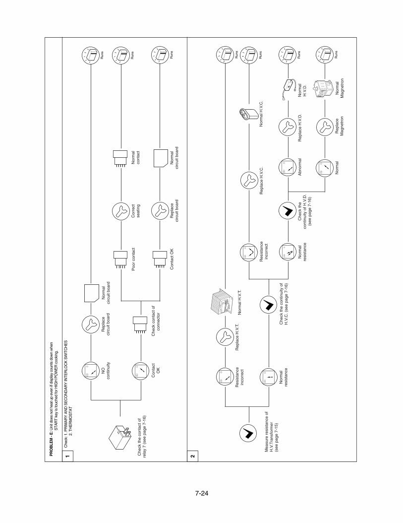
PR
OB
LEM
- E
: Uni
t doe
s no
t hea
t up
even
if d
ispl
ay c
ount
s do
wn
whe
nS
TAR
T ke
y is
touc
hed
for H
IGH
PO
WE
R c
ooki
ng.
Che
ck: 1
. PR
IMA
RY
AN
D S
EC
ON
DA
RY
INTE
RLO
CK
SW
ITC
HE
S2.
TH
ER
MO
STA
T1 2
Run
s
Run
s
Run
s
Con
tact
OK
NO
cont
inui
tyR
epla
ceci
rcui
t boa
rdN
orm
alci
rcui
t boa
rd
Poo
r co
ntac
t
Rep
lace
circ
uit b
oard
Nor
mal
circ
uit b
oard
Con
tact
OK
Nor
mal
cont
act
Cor
rect
seat
ing
Che
ck c
onta
ct o
fco
nnec
tor
Che
ck th
e co
ntac
t of
rela
y 7
(see
pag
e 7-
16)
Res
ista
nce
inco
rrec
t
Che
ck th
e co
ntin
uity
of
H.V
.C. (
see
page
7-1
6)
Nor
mal
H.V
.T.
Res
ista
nce
inco
rrec
tN
orm
al H
.V.C
.
Abn
orm
alR
epla
ce H
.V.D
.
Nor
mal
Mag
netr
onR
epla
ceM
agne
tron
Nor
mal
Nor
mal
H.V
.D.
Che
ck th
eco
ntin
uity
of H
.V.D
.(s
ee p
age
7-16
)
Rep
lace
H.V
.C.
Nor
mal
resi
stan
ce
Rep
lace
H.V
.T.
Nor
mal
resi
stan
ce
Run
s
Run
s
Run
s
Run
s
Mea
sure
res
ista
nce
ofH
.V.T
rans
form
er(s
ee p
age
7-15
)
7-25
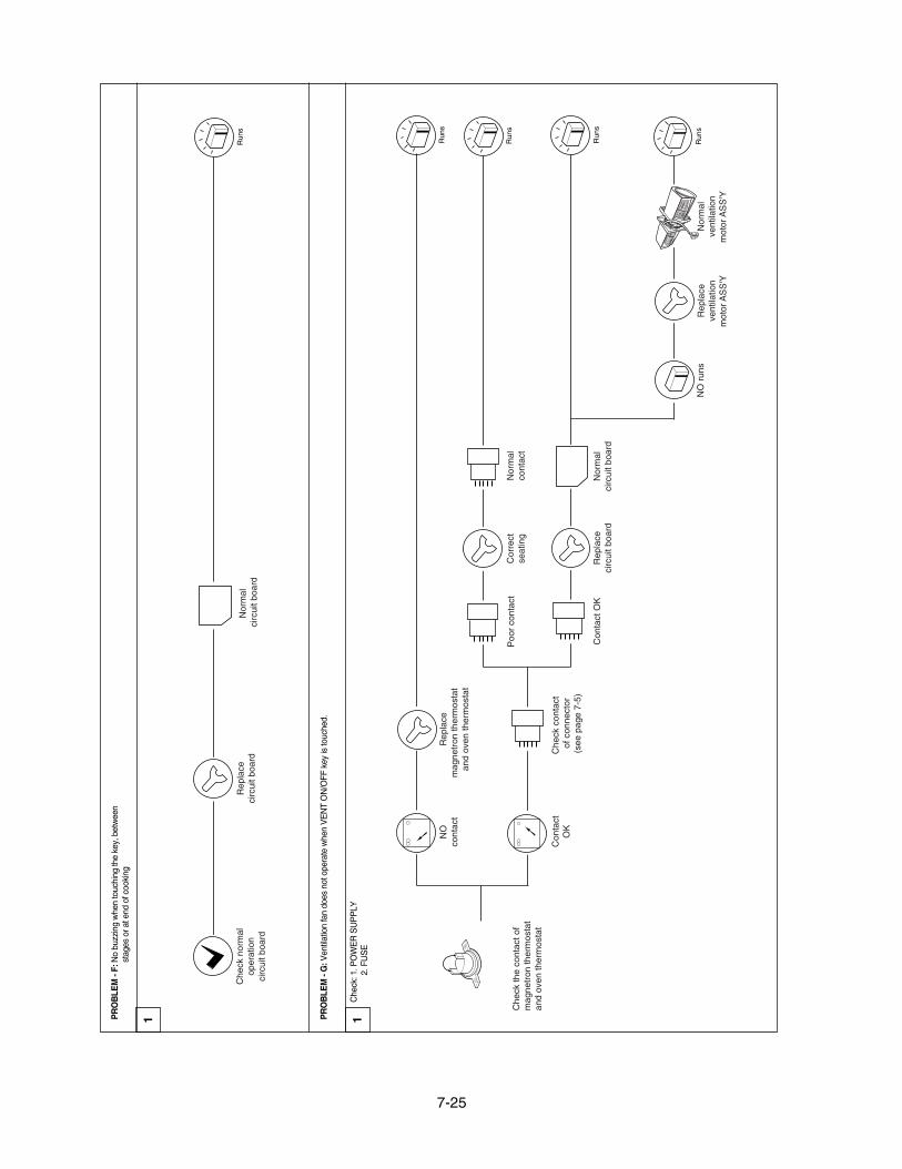
PR
OB
LEM
- F:
No
buzz
ing
whe
n to
uchi
ng th
e ke
y, b
etw
een
stag
es o
r at e
nd o
f coo
king
1
Nor
mal
circ
uit b
oard
Che
ck n
orm
alop
erat
ion
circ
uit b
oard
Rep
lace
ci
rcui
t boa
rdR
uns
PR
OB
LEM
- G
: Ven
tilat
ion
fan
does
not
ope
rate
whe
n V
EN
T O
N/O
FF k
ey is
touc
hed.
1
Run
s
Run
s
Run
s
Con
tact
OK
NO
cont
act
Rep
lace
mag
netr
on th
erm
osta
tan
d ov
en th
erm
osta
t
Poo
r co
ntac
t
Rep
lace
circ
uit b
oard
Nor
mal
circ
uit b
oard
Con
tact
OK
Nor
mal
cont
act
Cor
rect
seat
ing
Che
ck c
onta
ctof
con
nect
or
(see
pag
e 7-
5)
Run
sR
epla
ceve
ntila
tion
NO
run
sN
orm
alve
ntila
tion
Che
ck th
e co
ntac
t of
mag
netr
on th
erm
osta
tan
d ov
en th
erm
osta
t
Che
ck: 1
. PO
WE
R S
UP
PLY
2. F
US
E
8-1
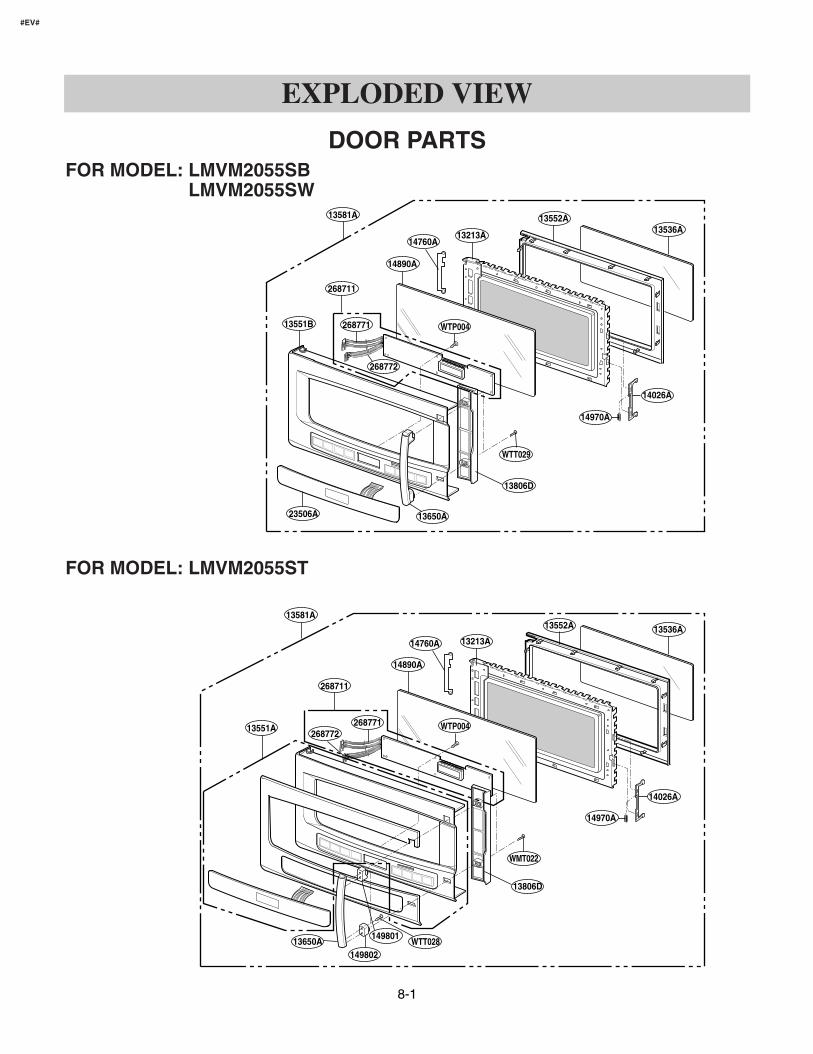
EXPLODED VIEW
DOOR PARTS
13536A
14890A
14890A
13551B
13581A
13581A
14760A
14760A
13213A
13213A
13552A
13552A
13536A
14026A
14026A
14970A
14970A
268771268772
13806D
13806D
13650A
13650A149802
149801
23506A
WTT029
WMT022
WTT028
WTP004
WTP00413551A
268771
268772
268711
268711
#EV#
FOR MODEL: LMVM2055SBLMVM2055SW
FOR MODEL: LMVM2055ST
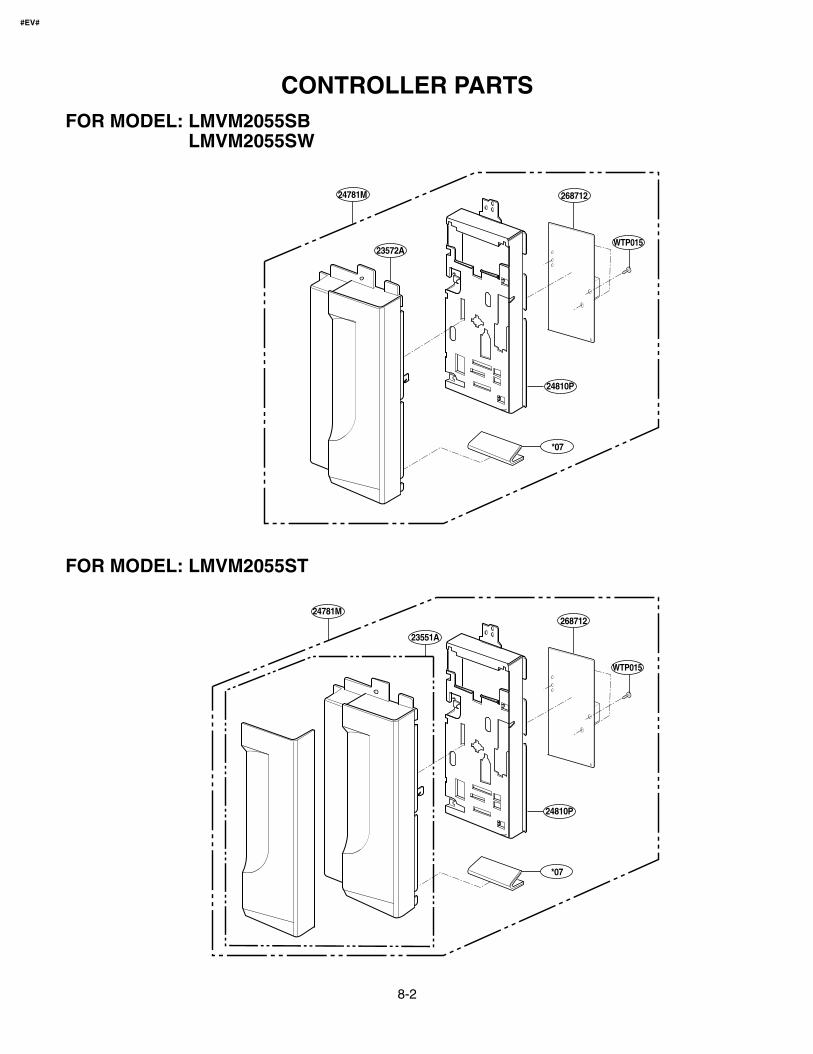
8-2
CONTROLLER PARTS
24781M
24781M
23572A
23551A
24810P
*07
*07
268712
WTP015
24810P
268712
WTP015
#EV#
FOR MODEL: LMVM2055SBLMVM2055SW
FOR MODEL: LMVM2055ST
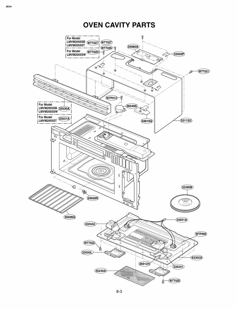
8-3
OVEN CAVITY PARTS
For ModelLMVM2055SBLMVM2055ST
For ModelLMVM2055SW
For ModelLMVM2055ST
For ModelLMVM2055SBLMVM2055SW
WTT027
WTT029
WTP013
WTT029
WTT027
WTT021
34960A
33550P
33112U34810Q
36549S33530A
34930R
33390M
35026G
33034234931A
WTP005
63302A
330341
WTT025
36912H
35230A
33550L
WTT022
33531A
#EV#
8-4
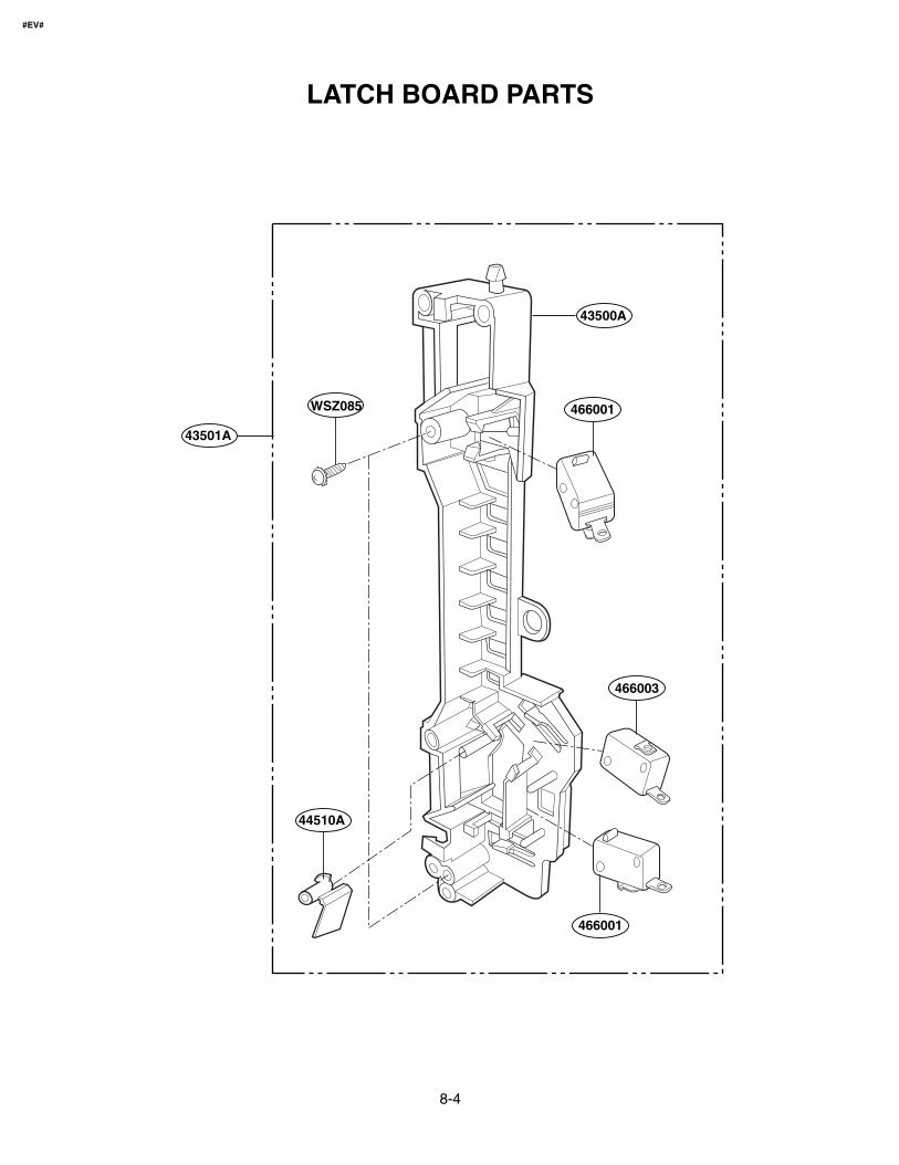
LATCH BOARD PARTS
WSZ085
44510A
466003
466001
466001
43501A
43500A
#EV#
8-5
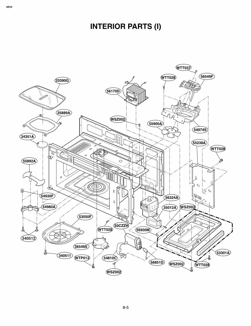
INTERIOR PARTS (I)
54980A
53550F
340511
WTT028
56851D
33390G
35889A
34351A
55892A
54930F
56549F
56170D
WTT037
WTT028
55900A
54974S
55238A
WTT028
WTT028WSZ002
WSZ002
36549S
WTP013
50CZZH
54810C
56324A
35012A WSZ002
WSZ002
53301A
56930M
340512
#EV#
8-6
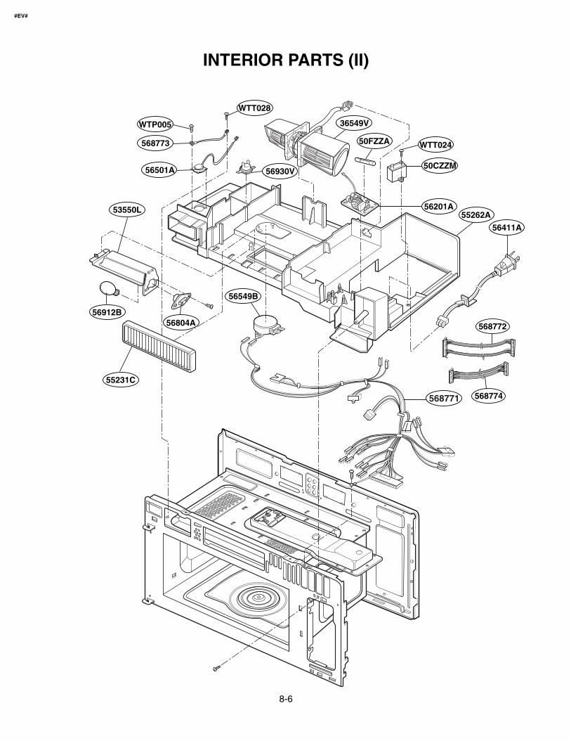
INTERIOR PARTS (II)
36549V
WTT024
WTT028
WTP005
568773
56501A
56549B
56201A
50CZZM
568771
56411A
50FZZA
55262A
55231C
56804A56912B
53550L
56930V
568772
568774
#EV#
8-7
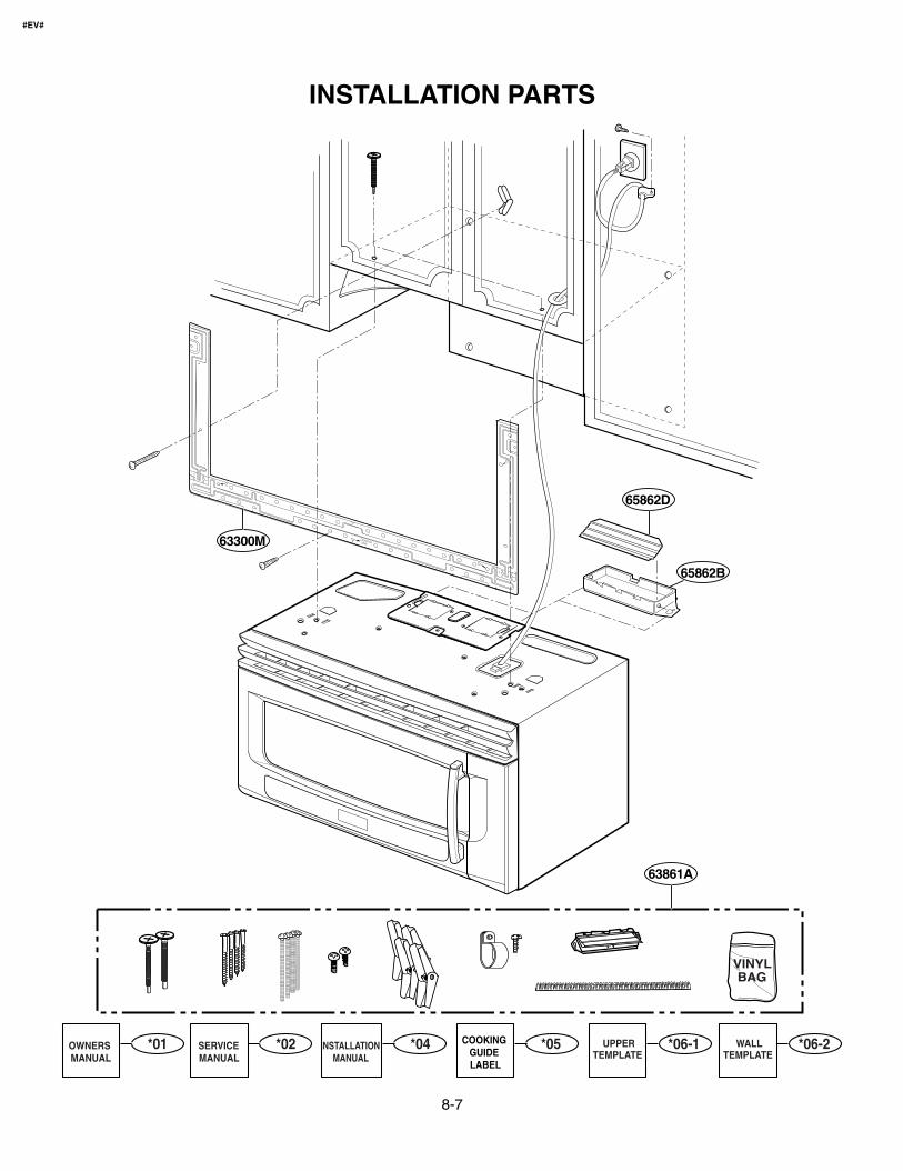
INSTALLATION PARTS
VINYLBAG
65862D
63861A
65862B
63300M
*01OWNERS MANUAL
*02SERVICEMANUAL
*06-1UPPERTEMPLATE
*06-2WALLTEMPLATE
*04INSTALLATIONMANUAL
*05COOKING GUIDE LABEL
#EV#