Server Appliance Network Operating System Technical Overview Copyright (C) 2003-2004 Michael...
67
Server Appliance Server Appliance Network Operating System Network Operating System Technical Overview Copyright (C) 2003-2004 Michael Ringgaard, jbox.dk, All rights reserved. sanos
-
date post
19-Dec-2015 -
Category
Documents
-
view
215 -
download
0
Transcript of Server Appliance Network Operating System Technical Overview Copyright (C) 2003-2004 Michael...

Server Appliance Server Appliance Network Operating SystemNetwork Operating System
Technical Overview
Copyright (C) 2003-2004 Michael Ringgaard, jbox.dk, All rights reserved.
sanos

SanOS Features 1
• Minimalistic application server operating system kernel.
• Open Source (BSD style license).
• Runs on standard PC hardware.
• 32-bit protected mode.• Interrupt driven.• Priority-based preemptive
multitasking.• Single address space.
• Kernel protection.• Virtual memory.• PE dynamically loadable
modules (standard EXE/DLL format).
• Both kernel and user modules.
• Low memory footprint (less than 512 KB RAM)
• Lightweight• Embedding support with
PC104 and Flash devices

SanOS Features 2
• Self configuring (PCI,PnP & DHCP support)
• TCP/IP networking stack
• Very efficient multithreading
• High performance and stability through simplicity.
• Written in C (98%) and x86 assembler (2%)
• Development using Microsoft Visual C.
• Remote source level debugging support (windbg)

Hardware
• Standard PC architecture
• IA-32 processor (486, Pentium)
• RAM (min. 4 MB)• IDE disk (UDMA)• IDE cdrom• Standard floppy• Serial ports• Keyboard• Video controller
• NIC support: – Novell NE2000– AMD PCNET32– 3Com 3C905– SiS900– RealTek 8129/8139– Intel EtherExpress Pro100

Core Operating System Services
• System booting and application loading• Memory Management
– Virtual memory mapping– Physical memory allocation and paging– Heap allocation and module loading and linking
• Thread Control– Thread scheduling and trap handling– Thread context– Thread synchronization and timers
• I/O Management– I/O bus and unit enumeration– Block devices and filesystems– Stream devices– Packet devices (NIC) and networking (TCP/IP)

Overview
Part 1: Architecture
Part 2: Boot Process
Part 3: Memory Management
Part 4: Thread Control
Part 5: I/O Management

Part 1
Architecture

System Components
application modules
os.dll
kernel modules and drivers
krnl.dll
osldr.dll
boot
User mode
Kernel mode
Bootstrap

Kernel Architecture
io memory thread boot
hw
api
cpu fpu iop pitpic
buf
sched
dbg
start
pframe pdir
ldr
kmem
vmm
kmalloc
vfs socket
udpsocktcpsockdfs
devfs
trap
dev
ether
netif
loopif
udptcp
ip
arp
icmp
dhcp
syscall
pcipnp
ide
fd serialconsole
kbdvideo pcnet32
ne2000
3c905c
blockblock
streamstream
packetpacket
busbus
smbfsqueue
ramdisk
null nvram
(...)
(nic...)
timer
procfs
pipefs
hndlobject
cdfs
iomux
apm

User Mode Components
os
applications/modules
sntp
kernel
sysapi
netdb
resolv thread
critsect
heap init
netnet
threadthread
memorymemory
bootboot
sh jinit ...
Ring 3 (user mode)
Ring 0 (kernel mode)
SYSENTER/SYSTRAP
jvm
tls
mod
signal
libc

Virtual Address Space Layout
• Virtual address space divided into kernel region and user region.
• Ring 0 code (kernel) can access all 4 GB.
• Ring 3 code (user) can only access low 2 GB addess space.
• Kernel and user segment selectors controls access to address space.
kernel
user
0x80000000
0x00010000
0xFFFFFFFF
0x00000000 invalid
user space(2 GB)
kernel space(2 GB)

Kernel Address Space Layout
kernel heap
handle table
page frame database
kernel modules
syspages
0x90800000
0x90400000
0x90000000
0xFFFFFFFF
0x80000000krnl.dll
page tables
0x91000000
0x92000000
syspage
page directory
video buffer
kmodmap
osvmap
initial tcb
dma buffers
biosdata
bootparams
idt
gdt
tss
datacode
devtabdevicetabbindtabintrtabready_queue
bucketskmods...
boot ram disk

User Address Space Layout
peb
os.dll
invalid
initial tib
user space
0x7FFDF000
0x7FF00000
0x00010000
0x80000000
0x00000000
heap

Segment selectors
Name GDT index Base Limit Access
NULL 0 0x00000000 0x00000000 None
KTEXT 1 0x00000000 0xFFFFFFFF Ring 0 CODE
KDATA 2 0x00000000 0xFFFFFFFF Ring 0 DATA
UTEXT 3 0x00000000 0x7FFFFFFF Ring 3 CODE
UDATA 4 0x00000000 0x7FFFFFFF Ring 3 DATA
TSS 5 Ring 0 TSS
TIB 6 Ring 3 DATA
Mode CS DS ES SS FS
kernel KTEXT KDATA KDATA KDATA TIB
user UTEXT UDATA UDATA UDATA TIB

Part 2
Boot Process

Boot process
1. BIOS initialization and loading of boot sector.2. Boot sector loads bootstrap loader (boot.asm).3. Real-mode initialization (ldrinit)4. Bootstrap loader sets up memory and loads kernel
(osldr.dll).5. Kernel initializes subsystems and starts main task
(krnl.dll).6. Main kernel task loads device drivers, mounts
filesystems and loads os.dll into user space.7. User mode component (os.dll) initializes user
module database, memory heap, and loads and executes the init application (e.g. sh.exe or jinit.exe).
8. All systems are GO. We are up and running.

Step 1: BIOS
• CPU reset starts executing ROM BIOS.
• BIOS initializes and configures computer and devices.
• BIOS loads the boot sector from sector 0 of the boot device (512 bytes) at 0x7C00.
• The BIOS jumps to 0:7C00 in 16 bit real-mode.
• Partitioned boot devices first loads the master boot record (mbr), which then loads and starts the boot sector in the active boot partition.
• When booting from CD or network the whole initial boot disk image is loaded by BIOS at 7C00. Because the boot sector is the first sector of the boot disk the bootstrap is executed.
osldr
0x000A0000
memend
0x00000000
BIOS ROM area
0x00007C00
boot stack
0x00090000
0x00100000heap
boot disk image
boot sectorBIOS data area

Step 2: Boot sector (boot)
• Depending on the boot device:– If booting from floppy or harddisk, loads the
osldr from boot device using BIOS INT 13 services
– If booting from CD or network, copies the osldr from the boot RAM disk image
• Calls real-mode entry point in osldr. The ”DOS-stub” in osldr.dll is used for real mode code in the loader.

Step 3: Real-mode initialization (ldrinit)
• Try to get system memory map from BIOS• Check for APM BIOS• Disables interrupts. Interrupts are reenabled
when the kernel has been initialized.• Enables A20. • Loads boot descriptors (GDT, IDT).• Initialize segment registers using boot
descriptors.• Switches the processor to protected mode
and calls 32-bit entry point

Step 4: Bootstrap loader (osldr.dll)
• Determines memory size.• Heap allocation starts at 1MB.• Allocate page for page directory.• Make recursive entry for access to page tables.• Allocate system page.• Allocate initial thread control block (TCB).• Allocate system page directory page.• Map system page, page directory, video buffer, and initial TCB.• Temporarily map first 4MB to physical memory.• If initial ram boot disk present copy it to high memory.• Load kernel from boot disk.• Set page directory (CR3) and enable paging (PG bit in CR0).• Setup descriptors in syspage (GDT, LDT, IDT and TSS).• Copy boot parameters to syspage.• Reload segment registers.• Switch to initial kernel stack and jump to kernel.

Step 5: Kernel startup (krnl.dll)
• Initialize memory management subsystem– Initialize page frame database.– Initialize page directory.– Initialize kernel heap.– Initialize kernel allocator.– Initialize virtual memory manager.
• Initialize thread control subsystem– Initialize interrupts, floating-point, and real-time clock.– Initialize scheduler.– Enable interrupts.
• Start main task• Process idle tasks

Step 6: Main kernel task (krnl.dll)
• Enumerate root host buses and units• Initialize boot devices (floppy and harddisk).• Initialize built-in filesystems (dfs, devfs, procfs, and pipefs).• Mount root device.• Load kernel configuration (/etc/krnl.ini).• Initialize kernel module loader.• Load kernel modules.• Bind, load and initialize device drivers.• Initialize networking.• Allocate handles for stdin, stdout and stderr.• Allocate and initialize process environment block (PEB).• Load /bin/os.dll into user space• Initialize initial user thread (stack and tib)• Call entry point in os.dll

Step 7: User mode startup (os.dll)
• Load user mode selectors into segment registers
• Load os configuration (/etc/os.ini). • Initialize heap allocator.• Initialize network interfaces, resolver and NTP
daemon• Initialize user module database.• Mount additional filesystems.• Load, bind and execute initial application.
Step 8: Execute application
• All systems are now up and running.
• The application uses the OS API, exported from os.dll to call system services.
• Examples: sh.exe and jinit.exe
OS API categories: • system• file• network• resolver• virtual memory• heap• modules• time• threads• synchronization• critical sections• thread local storage

OS API functions
canonicalizechdirchsizeclosedupflushformatfstatfstatfsfutimegetcwdgetfsstatioctllinklseekmkdirmountopenopendirreadreaddirreadvrenamermdirstatstatfstellumountunlinkutimewritewritev
fileacceptbindconnectgetpeernamegetsocknamegetsockoptlistenrecvrecvfromsendsendtosetsockoptshutdownsocket
socketbeginthreadendthreadepulseeresetesetgetcontextgetpriogettibgettidmkeventmksemraiseresumeselfsemrelsetcontextsetpriosignalsleepsuspendwaitwaitallwaitany
threadcsfreeenterleavemkcs
critsect
tlsalloctlsfreetlsgettlsset
tls
callocfreemallinfomallocrealloc
heap
dn_compdn_expandres_mkqueryres_queryres_querydomainres_searchres_send
resolver
gethostbyaddrgethostbynamegethostnamegetprotobynamegetprotobynumbergetservbynamegetservbyportinet_addrinet_ntoa
netdb
execgetmodpathgetmoduleloadresolveunload
module
clockgettimeofdaysettimeofdaytime
time
mlockmmapmprotectmremapmunlockmunmap
memory configdbgbreakexitloglevelpanicpebsyscallsyslog
system

Win32 subsystem
• Partial implementation of the following Win32 modules:– KERNEL32– USER32– ADVAPI32– MSVCRT– WINMM– WSOCK32

Java VM
• SanOS supports any standard pure Java server applications.
• Uses Sun Microsystems HotSpot Java VM for Win32.
• Supports standard JNI for native interface.
• jinit.exe loads the Java VM and starts the main method of the startup class.krnl.dll
os.dll
win32 subsysjinit
jvm
Java server application(e.g. tomcat, jboss)
(jni)
Java 2 SDK
hpi

Booting from CD-ROM
• BOOTIMG.BIN contains a small (512K) dfs boot filesystem image with cdboot as boot sector.
• The CD-ROM boot loader in the BIOS loads the 512K boot image into memory at 0x7C00.
• The cdboot bootsector in the first sector of BOOTIMG.BIN copies the osldr to 0x90000 and executes it.
• The kernel is copied from the boot image to high memory. The boot image is also copied to high memory.
• When the kernel is started a RAM disk (initrd) is created from the boot image and mounted on root. The rest of the CD-ROM is mounted on /usr.
System(unused)
Bootable CD-ROM imagesector 0
sector 16 Primary volume
Boot volumesector 17
…
Set terminator volume
BOOTCAT.BIN
BOOTIMG.BIN
File data for /usr
CD-ROM root dir

boot.jbox.dksanos01.jbox.dk
Booting from network
• PXE BIOS boot ROM sends DHCP request to obtain network and boot parameters.
• PXE BIOS retrieves 512K boot image (sanos.0) from TFTP server.
• The sanos.0 image is a boot image with a dfs filesystem. The first sector of the image contains the netboot boot sector.
• The netboot boot sector copies the osldr to 0x90000 and executes it.
• The kernel is copied from the boot image to high memory. The boot image is also copied to high memory.
• When the kernel is started a RAM disk (initrd) is created from the boot image and mounted on root. Then /usr is mounted on a remote SMB file share.
dhcpd
tftpd
smbd
PXE BIOSboot ROM
DHCPrequest
TFTPsanos.0
sanos kernel
mount /usr
host sanos01 { hardware ethernet 00:30:1b:ab:95:54; fixed-address sanos01.jbox.dk; filename "sanos/sanos.0"; next-server boot.jbox.dk;}
From /etc/dhcpd.conf on boot.jbox.dk:
Part 3
Memory Management

Memory management
• pdir.c controls the virtual memory mapping (pdir and ptab).
• pframe.c controls the allocation of physical memory (pfdb).
• kmem.c tracks the use of the kernel module and heap areas and allocation and mapping of physical pages to virtual addresses (osvmap and kmodmap).
• kmalloc.c allocates and deallocates small blocks (<4K) from the kernel heap (buckets). Larger blocks are delegated to kmem.
• vmm.c reserves virtual addresses in user space and commits and maps these to physical memory (vmap).
• heap.c is a standard C heap allocator (malloc, free, realloc) (Doug Lea) on top of the vmm.
pframe.c pdir.c
kmem.c
kmalloc.c
vmm.c
heap.c

Module Loader
• Both kernel and user mode DLL modules• Loading module
– Allocate module memory and load image from file– Resolve dependencies– Relocate module(s)– Bind imports– Protect module(s)– Initialize module(s)– Notify debugger– Update reference counts

Part 4
Thread Control

Thread control blocks
espthread object kernel stack
• Each thread has an 8K thread control block (tcb).• Each tcb is aligned on 8K boundary• tcbs are allocated on the kernel heap. • Initial kernel thread is allocated in syspage block.• esp0 in tss points to stack top in current tcb
tss
esp0

Thread information block (tib)
espthread object kernel stack
• Each user mode thread has a 4K thread information block (tib) allocated in user space.
• The format of the tib is compatible with win32.• The fs segment register always references the tib for the current
thread.• The tib contains the thread local storage array for the thread.• The tcb contains a reference to the tib for user mode threads.
tib
tls array
fs

User stacks
espthread object kernel stack
• Each user thread has a user mode stack• The first page of the stack is committed when it is created.• The rest of the pages in the stack are reserved with guard pages.• When the stack grows the guard page handler expands down the
stack and commits pages.
tib
reserved
stacktopstacklimitstackbase
committed
user stack

Enter kernel (1)
• trap/fault occurs (int, exception, interrupt)
espeip
eflags
eax ebxecx edxebp
esi edi
tcb
esp0
user stackuser code
kernel code

Enter kernel (2)
• trap/fault occurs (int, exception, interrupt)– push user esp on to kernel stack, load kernel esp
espeip
eflags
eax ebxecx edxebp
esi edi
tcb
esp0
user stackuser code
kernel code
essesp

Enter kernel (3)
• trap/fault occurs (int, exception, interrupt)– push user esp on to kernel stack, load kernel esp
– push user eflags, reset flags (IF=0, TF=0)
espeip
eflags
eax ebxecx edxebp
esi edi
tcb
esp0
user stackuser code
kernel code
essespflg

Enter kernel (4)
• trap/fault occurs (int, exception, interrupt)– push user esp on to kernel stack, load kernel esp
– push user eflags, reset flags (IF=0, TF=0)
– push user eip, load kernel entry eip
espeip
eflags
eax ebxecx edxebp
esi edi
tcb
esp0
user stackuser code
kernel code
ssespflg
Hardware programmedsingle instrution
cseip

Enter kernel (5)
• trap/fault occurs (int, exception, interrupt)– push user esp on to kernel stack, load kernel esp
– push user eflags, reset flags (IF=0, TF=0)
– push user eip, load kernel entry eip
• push error code
espeip
eflags
eax ebxecx edxebp
esi edi
tcb
esp0
user stackuser code
kernel code
ssespflgcseiperr
Hardware programmedsingle instrution

Enter kernel (6)
• trap/fault occurs (int, exception, interrupt)– push user esp on to kernel stack, load kernel esp
– push user eflags, reset flags (IF=0, TF=0)
– push user eip, load kernel entry eip
• push error code• push trap number, registers and set thread context pointer
espeip
eflags
eax ebxecx edxebp
esi edi
tcb
esp0
user stackuser code
kernel code
ssespflgcseiperrregs num
Hardware programmedsingle instrution

Context record
• Context record is a pointer into the kernel stack
• This record can be modified while in kernel mode
• Context record will be restored when the thread leaves the kernel
tcb
esp0
ssespflgcseiperrregs num
context record
struct context{ unsigned long es, ds; unsigned long edi, esi, ebp, ebx, edx, ecx, eax; unsigned long traptype; unsigned long errcode;
unsigned long eip, ecs; unsigned long eflags; unsigned long esp, ess;};

Current thread
• tcbs are aligned on 8K boundary• The current thread can be obtained from the value of the stack pointer
in kernel mode.
tcb
esp0
kernel stack
espeip
eflags
eax ebxecx edxebp
esi edimov ebx, espand ebx, -sizeof tcb

Context switch (1)
• Dispatcher calls context_switch to change context to another thread.• Caller pushes new tcb and return address on stack.
tcb
esp0
...
espeip
eflags
eax ebxecx edxebp
esi edi
esp
tcb
kernel code
esp
tcbeip

Context switch (2)
• Dispatcher calls context_switch to change context to another thread.• Caller pushes new tcb and return address on stack.• Registers are saved on current kernel stack.• Store kernel stack pointer in tcb.
tcb
esp0
...
espeip
eflags
eax ebxecx edxebp
esi edi
esp
tcb
kernel code
esp
eipebpesi edi ebx tcb

Context switch (3)
• Dispatcher calls context_switch to change context to another thread.• Caller pushes new tcb and return address on stack.• Registers are saved on current kernel stack.• Store kernel stack pointer in tcb.• Fetch stack pointer for new thread and store in esp0.
tcb
esp0
...
espeip
eflags
eax ebxecx edxebp
esi edi
esp
tcb
kernel code
esp
eipebpesi edi ebx
...eipebpesi edi ebx
tcb
tcb

Context switch (4)
• Dispatcher calls context_switch to change context to another thread.• Caller pushes new tcb and return address on stack.• Registers are saved on current kernel stack.• Store kernel stack pointer in tcb.• Fetch stack pointer for new thread and store in esp0.• Restore registers from new kernel stack.
tcb
esp0
...
espeip
eflags
eax ebxecx edxebp
esi edi
esp
tcb
kernel code
esp
eipebpesi edi ebx
...eip
tcb
tcb

Context switch (5)
• Dispatcher calls context_switch to change context to another thread.• Caller pushes new tcb and return address on stack.• Registers are saved on current kernel stack.• Store kernel stack pointer in tcb.• Fetch stack pointer for new thread and store in esp0.• Restore registers from new kernel stack.• Return from context_switch restores eip.
tcb
esp0
...
espeip
eflags
eax ebxecx edxebp
esi edi
esp
tcb
kernel code
esp
eipebpesi edi ebx
...
tcb

System calls (1)
• System calls are exported from os.dll. • All kernel system calls are handled by the syscall() function.• When a kernel system call is invoked a privilege transition from user
mode to kernel mode takes place, and the stack is switched from user stack to kernel stack.
• When the function returns these actions are reversed, the thread switches back to the user stack and returns to user mode privileges.
• Consider the system call function(param1, param2). Prior to this function being called, two parameters are pushed onto the user stack in reverse order.
• When function() is invoked, the return address is first pushed onto the user stack and then the old base pointer for the previous stack frame is pushed. The call stack after the call looks like: param2
param1ret addr
ebp

System calls (2)
• The implementation for function() is as follows: int function(param1, param2) { return syscall(SYSCALL_FUNCTION, ¶m1); }
• syscall() takes two parameters, a system call number, syscallno, and a pointer to the first parameter supplied to the function that calls syscall(). When syscall() is invoked, these two parameters are pushed onto the user stack in reverse order. The return address is pushed onto the stack when the call is made and the first action of the syscall() function is to push the base pointer onto the user stack.
• syscall() is an assembly language routine that causes a trap to the kernel through INT 48.
• Before doing this, it stores the system call number and pointer to the first parameter of the specific system call in the eax and edx registers, respectively.
syscall: push ebp mov ebp, esp mov eax, 8[ebp] mov edx, 12[ebp] int 48 leave ret
param2param1ret addr
ebp
syscallnoret addr
ebp
System calls (3)
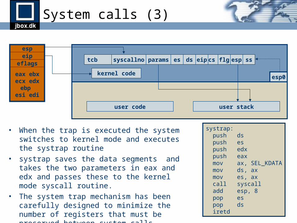
• When the trap is executed the system switches to kernel mode and executes the systrap routine
• systrap saves the data segments and takes the two parameters in eax and edx and passes these to the kernel mode syscall routine.
• The system trap mechanism has been carefully designed to minimize the number of registers that must be preserved between system calls.
• Support for sysenter/sysexit for Pentium processors.
espeip
eflags
eax ebxecx edxebp
esi edi
tcb
esp0
user stackuser code
kernel code
ssespflgcseipdsparams essyscallno
systrap: push ds push es push edx push eax mov ax, SEL_KDATA mov ds, ax mov es, ax call syscall add esp, 8 pop es pop ds iretd

Trap Frames
ssespflgcseiperrnumring 3 interrupt eaxecxedxebxebpesiedidses
ring 0 interrupt flgcseiperrnumeaxecxedxebxebpesiedidses
ssespflgcseiperrnumdsesint 48 syscall
sysenter syscall esp eipnumdses
paramssyscallno
paramssyscallno

Thread states
• Threads are created in INITIALIZED state.• When mark_thread_ready() is called the thread
moves to the READY state and is inserted into one of the wait queues.
• When the scheduler selects the thread for execution it moves to the RUNNING state and the dispatcher swicthes the processor to the threads context.
• The thread continues running until it must wait on an object to become signaled (blocked) or its quantum expires (preempted).
• If the quantum expires the thread is marked as READY and the next ready thread is moved to the RUNNING state.
• If the thread is blocked the thread is added to the waitlist for the object and enters the WAITING state.
• When the object is signaled the thread is scheduled for execution by inserting it into the ready queue for the threads priority. The thread enters the READY state.
• When the thread terminates it enters the TERMINATED state. The thread object is not removed until all handles to it has been closed.
INITIALIZED
READY
TERMINATED
WAITINGRUNNING

31
30
29
...
Scheduling
• Each thread has a dynamic and a base priority.
• Threads that are ready to run are scheduled in a round-robin manner based on priority.
• A thread is not scheduled until no higher priority threads are ready to run.
• The scheduler has one ready queue for each priority level.
• Time slice is 36 quantum units• Three quantum units charged per tick (10
ms)• One quantum unit charged each time a
thread is restarted after a wait.• Running thread preempted when higher
priority thread gets ready to run.• Priority boosting is applied to thread when
started after an I/O wait.• Boosting never moves threads to the real-
time range.• Boosting is applied to the base priority.• Dynamic priority is decreased (decayed) at
each quantum expiry until it reaches base priority.
16
highest priority
lowest priority
15
14
...
3
2
1
0
threadthread
thread
thread
thread
real
-tim
e ra
nge
dyna
mic
ran
ge

Synchronization objects
• Object types– THREAD– EVENT– TIMER– MUTEX– SEMAPHORE– FILE– SOCKET– IOMUX

Thread synchronization
• The object header contains the object type, signaled state, and a list of the threads waiting on the object.
• The waitblock represents a thread waiting on an object.
• Each thread has a list of the objects it is waiting on.
thread 1
wait list
thread 2
wait list
object a
waitlist
object b
waitlist
waitblock
next
threadobject
waiter links
waitblock
next
threadobject
waiter links
waitblock
next
threadobject
waiter links

Signal handling
• Signal handlers are registered with signal().• When a trap occurs send_signal() is called by the kernel trap handler.• The context record is pushed into the user stack.• Parameters to global signal handler are pushed onto the stack. • The EIP register in the context record is change to the address of the
global signal handler.• This causes the global signal handler in signal.c to be invoked when the
thread leaves the kernel.• The global signal handler uses the signal handler table to dispatch the
signal to the signal handler.• When the signal handler returns the global signal handler uses int 49 to
call the sigexit handler in the kernel.• The sigexit handler in the kernel restores the context and resumes
execution of the thread.• The signal handler can change the context record or use longjmp() to
alter the execution of the thread.

Part 5
I/O Management

I/O Components
• Device Drivers
• Device Manager
• Virtual File System layer and filesystems
• Socket interface and networking
• I/O multiplexing

Device types
• Bus device (enumerate)– pci– isapnp
• Block device (read, write)– fd– hd– cd
• Stream device (read, write)– console– serial
• Packet device (receive, transmit)– 3c905c– ne2000– pcnet32– eepro100– sis900– rtl8139

File systems
• Virtual File System (vfs)• File systems
– dfsNative sanos disk file system
– devfs Device file system (/dev)
– procfs Kernel information file system (/proc)
– pipefs Pipe file system (for pipe())
– smbfs Remote SMB file system (Windows file shares)
– cdfs CD-ROM file system (ISO-9660)
• Buffer Cache Manager

Disk file system layout
block 0 block 1 block 2 block 3 ... block n
boot sector
super block
reservedblocks(osldr)
groupdescriptor
table
inodebitmap
inodetable
blockbitmap
datablocks
inodebitmap
inodetable
blockbitmap
datablocks
sector 0 sector 1 sector 2 sector 3 ... sector n
group 0 group 1 group 2 group 3 ... group n
Group 0:
Group n:
Block:
Group:
Device:

Cache buffer states
FREE
READING
WRITINGCLEAN DIRTY
LOCKED UPDATE
INVALID

Networking
• Socket interface (tcp and udp sockets)• Network interface (netif)• Protocols
– TCP– UDP– IP– ICMP– DHCP– DNS– ARP– IEEE 802.3 (Ethernet)

Design Principles
Performance Flexibility
Simplicity
sanos

Logo