Separation Process 1
86
FKK DISTILLATION • 2 methods of distillation: • eg. Ethanol-water: vapour phase = higher conc. of ethanol liquid phase = higher conc. of water • separation of different components in a liquid solution • involved producing a vapour from a liquid by heating the liquid in a vessel rectification/fractional/distillation with reflux – part of the vapour is condensed & returned as liquid back to the vessel all of the vapour is removed or is condensed as product
description
Distillation Process
Transcript of Separation Process 1

FKK
DISTILLATION
• 2 methods of distillation:
• eg. Ethanol-water:
vapour phase = higher conc. of ethanol
liquid phase = higher conc. of water
• separation of different components in a liquid solution
• involved producing a vapour from a liquid by heating the liquid in a vessel
rectification/fractional/distillation with reflux – part of the vapour is condensed & returned as
liquid back to the vessel
all of the vapour is removed or is condensed as product

FKK
DISTILLATION

FKK
DISTILLATION
• steam
• fractional
• extractive
Types of distillation:
• simple
immiscible solvent
azeotropic
vacuum
molecular
entrainer sublimation Distillation tower at an oil refinery.

FKK
VAPOUR-LIQUID EQUILIBRIUM RELATIONS
• ideal solution (substances very similar to each other)
RAOULT’S LAW
pA = partial pressure of component A in the vapour
• vapour & liquid in intimate contact for a long time, equilibrium is attained
pA = PAxA or yA =(pA/P)=(PA/P)xA
where
PA = vapour pressure of pure A
xA = mole fraction of A in the liquid
yA = mole fraction of A in the gas
P= total pressure

FKK
Vapour-liquid equilibrium for A-B mixture eg. benzene(A)-toluene (B)
BOILING-POINT DIAGRAMS & x-y PLOTS (VLE diagrams)
heat a mixture of benzene-toluene at xA1 = 0.318( boil at 98oC), first vapour in equilibrium is yA1 = 0.532
distance bet. equilibrium & 45o line = diff. bet. xA & yA ( 〉 diff., easier separation)

FKK
VLE diagrams
non-ideal systems which will present more difficult separation
An azeotrope is a liquid mixture which when vaporised, produces the same composition as the liquid.

FKK
RELATIVE VOLATILITY OF VAPOUR-LIQUID SYSTEMS
yA = mole fraction of A in the gas phase
Relative volatility, α - numerical measure of ease of separation
αAB - relative volatility of component A with respect to component B
where
xA = mole fraction of A in the liquid which is in equilibrium with yA phase
For an ideal system (obeys Raoult’s law):
€
αAB =
yAxAyBxB
=y
A/x
A
1−yA
/ 1−x
A
€
yA = αxA1+ α−1
xA
where
€
αAB = PAPB
= vapour pressure of pure Avapour pressure of pure B
when α 〉 1 , separation is possible

SINGLE-STAGE EQUILIBRIUM CONTACTOR
Binary distillation - components A & B
xA1 xA0
yA1 yA2
Total material balance: L0 + V2 = L1 + V1
Balance on A: L0xA0 + V2yA2 = L1xA1 + V1yA1
Unknown : x1 & y1 – solve simultaneously (graphically) between equilibrium line & overall material balance
FKK
Constant molal overflow: V1 = V2
L0 = L1

Example 11.2-1
• A vapor at the dew point and 101.32 kPa containing a mole fraction of 0.4 benzene (A) and 0.6 toluene (B) and 100 kg mol total is brought into contact with 110 kg mol of a liquid at the boiling point containing a mole fraction of 0.30 benzene and 0.70 toluene. The two streams are contacted in a single stage, and the outlet streams leave in equilibrium with each other. Assume constant molar overflow. Calculate the amounts and compositions of the exit streams.

SINGLE-STAGE EQUILIBRIUM CONTACTOR
Example 11.2-1
Balance on A: L0xA0 + V2yA2 = L1xA1 + V1yA1
FKK
Constant molal overflow: V1 = V2= 100 kmol
L0 = L1 = 110 kmol
xA1 xA0 =0.3
yA1 yA2 =0.4
=100 kmol
=110 kmol
110(0.3) + 100(0.4) = 110xA1 + 100yA1
lets xA1 = 0.2, yA1 = 0.51 lets xA1 = 0.4, yA1 = 0.29
lets xA1 = 0.3, yA1 = 0.4 At intersection, xA1 = 0.25, yA1 = 0.455

SIMPLE DISTILLATION METHODS
• Single stage binary distillation
• vapour & liquid then separated
Balance on A: FxF = Lx + Vy or FxF = (F-V)x + Vy Unknown : x & y – solve simultaneously (graphically) between equilibrium
line & overall material balance similar to eg. 11.2-1
FKK
• liquid mixture partially vapourized
• vapour allowed to come to equilibrium with liquid
Separator F,xF
Heater
V,y
L,x
EQUILIBRIUM OR FLASH DISTILLATION

SIMPLE DISTILLATION METHODS
• liquid mixture charged to a still (heated kettle)
• first portion of vapour = richest in component A
unknown: x2
L1x1 = L2x2 + (L1-L2)yav
Average composition of total material distilled, yav:
FKK
• slowly boiled & vapourized part of the liquid • vapour withdrawn rapidly to condenser
SIMPLE BATCH OR DIFFERENTIAL DISTILLATION
• vapourized product gets learner in comp. A
V, y
L, x
L1 = original moles charge
x1 = original composition
L2 = moles left in the still
x2 = final composition of liquid
∫ −= 1
2
xx
2
1xy
dxLLln
Graphical solution:
area under the curve 1/(y-x) vs x plot = 2
1LLln

Example 11.3-2
• A mixture of 100 mol containing 50 mol% n-pentane and 50mol% n-heptane is distilled under differential conditions at 101.3 kPa until 40 mol is distilled. What is the average composition of the total vapor distilled and the composition of the liquid left? The equilibrium data are as follows, where x and y are mole fractions of n-pentane:

The equilibrium data are as follows, where x and y are mole fractions of n-pentane:
x y x y x y
1.000 1.000 0.398 0.836 0.059 0.271
0.867 0.984 0.254 0.701 0 0
0.594 0.925 0.145 0.521

Example 11.3-2
Total balance : L1 = V + L2
FKK
Equilibrium data:
100 = 40 + L2
L2 = 60 mol
L1 = 100 mol
x1 = 0.5 mol /mol
V = 40 mol
x2 = ? , yav = ?
x 1.0 0.867 0.594 0.398 0.254 0.145 0.059 0 y 1.0 0.984 0.925 0.836 0.701 0.521 0.271 0
∫ −= 1
2
xx
2
1xy
dxLLln
0.51xydx
60100ln 0.5
x2=∫ −=
By trial-&-error, x2 = 0.277
L1x1 = L2x2 + (L1-L2)yav
100(0.5) = 60(0.277)+ (100-60)yav
yav = 0.835

FKK
McCABE-THIELE METHOD
• assume equimolar overflow/constant molal overflow between
feed inlet & top tray
feed inlet & bottom tray
• graphical method for determining the number of theoretical stages,N
• binary mixture A-B

q line
• Effect of feed condition (q line)
• q=heat needed to vaporize 1 mol of feed at entering conditions per molar latent heat of vaporization of feed.
• q-line equation:

McCabe-Thiele Method
• Graphical method requires: • i.Top Operating Line • ii.Feed Operating Line (q-line) • Iii.Bottom Operating Line

Feed Operating Line (q-line) • q-line equation: • Lm=Ln + qF • Vn=Vm + (1-q)F • Vny=Lnx+DxD (Top) ---(1) • Vmy=Lmx – WxW (Bottom)-----(2) • (2)-(1): • (Vm-Vn)y=(Lm-Ln)x-(DxD-FxF) • (Vm-Vn)y=(Lm-Ln)x – FxF
• Lm-Ln=qF • Vm-Vn=(q-1)F

q-line cont’
• (q-1)Fy = qFx – FxF
• y = [(q)/(q-1)]x – xF/(q-1)

q-line cont’
• q value depends on feed conditions: • If feed is liquid at boiling pt: q=1 • If feed is saturated vapor:q=0 • If feed is liquid below its boiling pt:q>1 • If feed is a mix bet. Liq & vap: 0<q<1

Example 11.4-1 • A liquid mixture of benzene-toluene is to be distilled in a
fractionating tower at 101.3 kPa pressure. The feed of 100 kg mol/h is liquid, containing 45 mol% benzene and 55 mol% toluene, and enters at 327.6 K(130oF). A distillate containing 95 mol% benzene and 5 mol% toluene and a bottoms containing 10 mol% benzene and 90 mol% toluene are to be obtained.The reflux ratio is 4:1. The average heat capacity of the feed is 159 kJ/kg mol.K (38 btu/lb mol.oF) and the average latent heat 32099 kJ/kg mol (13800 btu/lbmol). Equilibrium data for this system are given in Table 11.1-1.Calculate the kg moles per hour distillate, kg mole per hour bottoms, and the number of theoretical trays needed.

FKK
Example 11.4-1 Binary mixture A-B (benzene-toluene) at 101.3kPa. Reflux ratio (R) = 4. Average heat capacity of feed = 159 kJ/kmol.K & average latent heat = 32099 kJ/kmol. Determine D kmol/h, W kmol/h & N theoretical trays needed.
D kmol/h
xD = 0.95
W kmol/h
xW = 0.1
F =100 kmol/h
xF = 0.45
TF = 327.6K
Total material balance: F =100 =D + W
Balance on benzene (A): FxF = DxD + WxW
100(0.45) = D(0.95) + W(0.1)
45 = (100-W)(0.95) + W(0.1)
D =100 - W
Substituting D = 100-W
45 = 95 +(W)(0.95) + W(0.1)
W = 58.8 kmol/h D = 100-58.8 = 41.2 kmol/h

FKK
Example 11.4-1
2. Draw enriching operating line
R = 4 = L/D
D kmol/h
xD = 0.95
W kmol/h
xW = 0.1
F =100 kmol/h
xF = 0.45
TF = 327.6K
L
1Rxx1R
Ry D+
++
=
0.190.8x140.95x14
4y +=+
++
=
1. Plot equilibrium & 45o lines on x-y graph

FKK
Example 11.4-1
3. Calculate q (fraction of feed that is liquid)
LV
FBPLV
LV
FVHH
)T(TcHHHHHHq
−−+−
=−−
=
32099327.6)(159)(T32099
q B −+=
Average heat capacity of feed =159 kJ/kmol.K
Average latent heat 32099 kJ/kmol
From Fig. 11.1-1, at xF = 0.45, TB = 93.5oC (366.7K)
1.19532099327.6)7(159)(366.32099
q =−+
=

FKK
Example 11.4-1
q = 1 (liquid at its boiling point) , q = 0 (saturated vapour) , q 〉 1 (cold liquid feed)
q 〈 0 (superheated vapour) , 0 〈 q 〉 1 (mixture of liquid & vapour)

FKK
Example 11.4-1
Slope = 6.12 = Δy/Δx = (0.45 – y)/(0.45-x)
q = 1.195
€
y= qq−1
x− xF
q−1
€
y= 1.1951.195−1x− 0.45
1.195−1= 6.12x−2.31
4. Draw q-line
0.05y0.45
0.40.45y-0.45
x0.45y-0.456.12 −=
−=
−=
Lets x = 0.40
y = 0.144 5. Draw stripping operating line
Connect xW(on 45o line) with the point of intersection of the q-line & the enriching operating line
q-line

FKK
Example 11.4-1
Starting from xD, make steps bet. equilibrium line & enriching line to q-line
6. Stepping off from xD
7. Shift to stripping line after passing q-line
8. Feed location = tray on the shift
9. Ntheo. stages = number of steps
10. Ntheo. trays = theo. stages - reboiler
Feed tray = tray 5 from the top
Ntheo. trays = 8 – 1= 7 trays plus a reboiler
Ntheo. stages = 8 stages
Feed tray
12
3
4
5
6
7
8

FKK
TOTAL REFLUX, R = ∞ • minimum number of stages, Nmin
• stepping off from xD to xW on the 45o line
• operating lines coincide with 45o line • infinite sizes of condenser, reboiler & tower diameter
• or using Fenske equation (total condenser)
€
Nmin =log xD
1−xD
1−xWxW
log αav
αav = average value of relative volatility = (α1αW)½
α1= relative volatility of the overhead vapour
αW= relative volatility of the bottom liquid

Example 11.4-2
For the rectification in Example 11.4-1, where a benzene-toluene feed is being distilled to give a distillate composition of xD=0.95 and a bottoms composition of xW=0.10, calculate the following:
(a) Minimum reflux ratio Rmin
(b) Minimum number of theoretical plates at total reflux.

41.2 kmol/h
xD = 0.95
58.8 kmol/h
xW = 0.1
F =100 kmol/h
xF = 0.45
FKK
Example 11.4-2
At R = ∞, Nmin = ?
Nmin = 5.8 stages or 4.8 trays plus a reboiler
Steps are drawn from xD to xW.

FKK
MINIMUM REFLUX, Rmin
• infinite number of stages/trays
• Rmin at pinch point (x’,y’)
• minimum vapour flow • minimum condenser & reboiler
• or when equilibrium line has an inflection, operating line tangent to the equilibrium line
1Rxx1R
Ry D+
++
=
Enriching op. line:
y-intercept: intercepty
1R0.95
1Rx
minmin
D −=+
=+

Minimum Reflux Ratio
• The top operating line intercepts q-line at equilibrium line.
• The line passes through the points (x’,y’) and (xD,xD):

OPERATING AND OPTIMUM REFLUX RATIO
Two limits of tower operation exist: At total reflux -minimum number of plates with infinite tower diameter -cost of tower, steam & cooling tower increases.
At minimum reflux -infinite number of tray -infinite cost of tower. So, actual operating reflux ratio lies between total reflux and
minimum reflux (Rmin).
Normally, Ractual=1.2 -1.5 of Rmin

EXAMPLE 11.4-2
• For the rectification in Example 11.4-1, where a benzene-toluene feed is being distilled to give a distillate composition of xD=0.95 and a bottoms composition of xW=0.10, deretmine the following:
• (a) Minimum reflux ratio Rmin. • (b) Minimum number of theoretical plates at
total reflux (Nmin).

41.2 kmol/h
xD = 0.95
58.8 kmol/h
xW = 0.1
F =100 kmol/h
xF = 0.45
FKK
Example 11.4-2
Given R = 4, Rmin = ?
Rmin = 1.21
The enriching op. line from xD is drawn through the intersection of the q-line & the equilibrium line to intersect the y-axis
1Rxx1R
Ry D+
++
=
Enriching op. line:
y-intercept: 0.43
1R0.95
1Rx
minmin
D =+
=+

SPECIAL CASE DISTILLATION
• 1.Stripping column distillation • 2.Enriching column distillation • 3.Rectification with direct steam injection • 4.Rectification tower with side streams • 5.Partial condensers

FKK
STRIPPING-COLUMN DISTILLATION • feed is saturated liquid at boiling point (q=1)
• added to the top of the column • overhead product is not returned back to the tower
• operating line: 1m
Wm
1m
m
VWx
xVLy
++
−=
• Ntheo. stages - starting from xW(on 45o line) draw a straight line to the intersection of yD with the q-line

FKK
ENRICHING-COLUMN DISTILLATION • feed is saturated vapour (q=0)
• added to the bottom of the column • overhead product is refluxed back to the tower
• operating line: 1R
xx1R
Ry D
++
+=
• N theo. stages - starting from xD(on 45o line) draw a straight line to the y-intercept, xD/(R+1)
F
D
W
xD xF

FKK
DIRECT STEAM INJECTION
• steam injected as small bubbles into liquid
• stripping operating line: WxSWxS
Wy −=
• heat provided by open steam injected directly at bottom of tower
• draw a straight line from (xW,0) through WxW/(W-S) on the 45o line
• use of open steam requires an extra fraction of a stage

FKK
SIDE STREAM
• side stream above feed inlet:
intermediate operating line: 1S
DO
1S
S
VDxOx
xVLy
++
++=
• stream removed from sections of tower
liquid side stream: Ln = LS+O
VS+1 = Vn+1=V1=Ln+D
• from the intersection of enriching op. line & xO, draw a straight line to y-intercept of intermediate op. line

FKK
PARTIAL CONDENSERS
• liquid condensate returned to tower as reflux
• overhead product = vapour
• one extra theoretical stage for partial condenser (both liquid & vapour in condenser is in equilibrium)

FKK
TRAY EFFICIENCY
• Overall tray efficiency, Eo 3 types of tray efficiency:
• Murphree tray efficiency, EM
• Point/local tray efficiency, EMP
trays actual of no.trays ideal of no.EO =
1nn
1nnMP -y'*y
-y'y'E+
+=
1nn
1nnM -y*y
y-yE+
+=
FKK
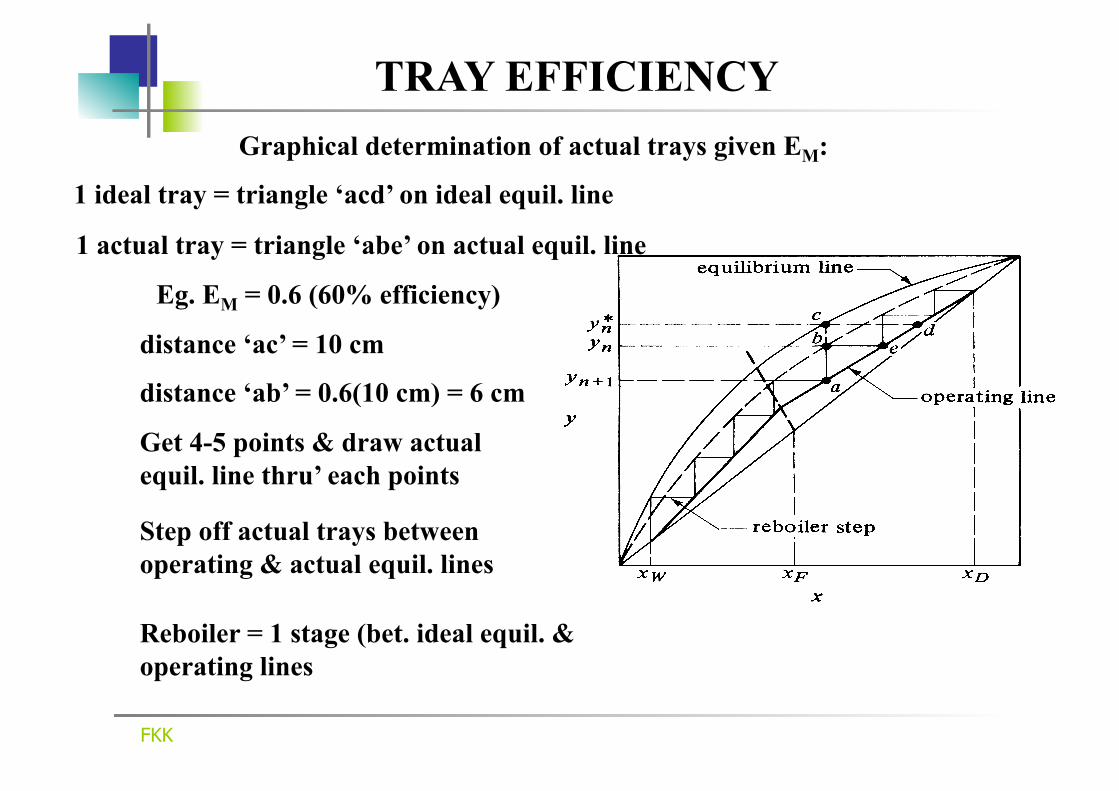
TRAY EFFICIENCY
1 actual tray = triangle ‘abe’ on actual equil. line
1 ideal tray = triangle ‘acd’ on ideal equil. line
Eg. EM = 0.6 (60% efficiency) distance ‘ac’ = 10 cm
Graphical determination of actual trays given EM:
Reboiler = 1 stage (bet. ideal equil. & operating lines
distance ‘ab’ = 0.6(10 cm) = 6 cm
Get 4-5 points & draw actual equil. line thru’ each points
Step off actual trays between operating & actual equil. lines

Problem (Tray efficiency)
• No 11.5-1 (pg 755): • For the distillation of heptane and ethyl
benzene in problem 11.4-2, the Murphree tray efficiency is estimated as 0.55. Determine the actual number of trays needed by stepping off the trays using the tray efficiency of 0.55. Also, calculate the overall tray efficiency Eo.

Condenser Duty (qc) • Enthalpy Balance Around the Condenser: • V1(H1) =L(hD) + D(hD) + qc
• qc=VHD – (LhD+DhD)
• For total condenser: • V1=VD, HD=H1 • H1=the saturated vapor enthalpy (equation 11.6-2):
• H1 can also be determined from the enthalpy-concentration diagram

Reboiler Duty (qR) • Overall Enthalpy Balance :
• Enthalpy in = Enthalpy out
• qR +Fhf = qc + DhD + WhW
• qR =qc + DhD + WhW – Fhf
• hD and hf from equation (11.6-1) or from the enthalpy-concentration diagram.

Example • Binary mixture A-B (benzene-toluene) is to be distilled in a
fractionation column 101.3kPa. The feed of 100 kgmol/h is liquid, containing 45 mol% benzene and 55 mol% toluene, and enters at 327.6 K. A distillate containing 95 mol% benzene and 5 mol% toluene and a bottoms containing 10 mol% benzene and 90 mol% toluene are to be obtained. A Reflux ratio (R) = 1.5Rm. Given that Rm=1.17. Determine the condenser duty and the reboiler duty required by the distillation column by assuming constant molar overflow. Physical property for benzene and toluene and enthalpy-concentration diagram are given in Table 11.6-1(pg 733) and Table 11.6-2 (pg 734), respectively.

FKK
ENTHALPY-CONCENTRATION METHOD
• no assumption of molal overflow rates
• takes into account latent heats, heats of solution & sensible heats
• Ponchon-Savarit method
• graphical procedure combining enthalpy & material balances
• provides information on condenser & reboiler duties

FKKKSA
• calculation shown in eg. 11.6-1
• data Table 11.6-2 pg. 734 (Geankoplis 4th Ed.)
Enthalpy-concentration for benzene-toluene

FKKKSA
ENTHALPY-CONCENTRATION METHOD
Drawing isotherms (tie lines) on the enthalpy-concentration diagram from
(a) temperature-concentration diagram (b) x-y diagram

41.2 kmol/h
xD = 0.95
58.8 kmol/h
xW = 0.1
F =100 kmol/h
xF = 0.45
TF = 327.6K
L
FKKKSA
Example 11.6-2
Given : R = 1.5 Rm = 1.5(1.17) = 1.755
1. Plot enthalpy-concentration diagram and x-y diagram on the same sheet of paper. Locate points D, W and F at xD, xW and xF, respectively.
hF = xFcpA(TF-T0) + (1-xF)cpB(TF-T0)
where cpA = cp of liquid benzene = 138.2 kJ/kmol.K
cpB = cp of liquid toluene = 167.5 kJ/kmol.K
T0 = Tref. = Tb.p. of liquid benzene = 80.1oC
hF= 0.45(138.2)(327.6-353.1) + (1-0.45)167.5(327.6-353.1) = -3938.1 kJ

FKKKSA
Example 11.6-2
-140.0
-120.0
-100.0
-80.0
-60.0
-40.0
-20.0
0.0
20.0
40.0
60.0
80.0
100.0
120.0
140.0
0.0 0.2 0.4 0.6 0.8 1.0
0
0.2
0.4
0.6
0.8
1
0 0.2 0.4 0.6 0.8 1
W
DF

FKKKSA
Sat. vapour
Sat. liquid hD
H1
ΔR hD+QC/D
V1
1RHÄ
1DHh
Locating ΔR
2. Locate rectifying-section difference point,ΔR
D1
1R
D1
1C
D
hHHÄ
hH
HDQh
R =−
−+=

-140.0
-120.0
-100.0
-80.0
-60.0
-40.0
-20.0
0.0
20.0
40.0
60.0
80.0
100.0
120.0
140.0
0.0 0.2 0.4 0.6 0.8 1.0
0
0.2
0.4
0.6
0.8
1
0 0.2 0.4 0.6 0.8 1
W
DF
FKKKSA
Example 11.6-2
1cmHÄ
1.755hHHÄ
hH
HDQh
R 1R
D1
1R
D1
1C
D===
−
−+=
1.755cm1cm1.755HÄ 1R ==
∆R ΔR =85x 103kJ/kmol
hW=5x 10³kJ/kmol
H1=31x 103kJ/kmol V1
D1
1R
D1
1C
D
hHHÄ
hH
HDQh
R =−
−+=

FKKKSA
3. Locate stripping-section difference point, ΔS
4. Step off trays for rectifying section using ΔR. 5. Step off trays for stripping section using ΔS
D1
1C
D
hH
HDQh
R−
−+=
Example 11.6-2
6. Theoretical stages = numbers of tie lines
7. Theoretical trays = theoretical stages - reboiler
8. Feed tray = tie line that crosses the line SRFÄÄ
9. Condenser duty, QC = (ΔR –hD)D or
10. Reboiler duty, QR = (hW-ΔS)W
Theoretical trays = 11.9 – 1 = 10.9 trays
Feed trays = tray no. 7 from the top
QC = (85x103-0)41.2 = 3 460 800 kJ/h
QR = (hW-ΔS)W = (5 x 10³ –[-64x103])58.8 = 4 057 200 kJ.h

FKKKSA
Locating ΔS
Draw a straight line from ΔR through F to intersect the vertical line at xW

FKKKSA
Example 11.6-2
-140.0
-120.0
-100.0
-80.0
-60.0
-40.0
-20.0
0.0
20.0
40.0
60.0
80.0
100.0
120.0
140.0
0.0 0.2 0.4 0.6 0.8 1.0
0
0.2
0.4
0.6
0.8
1
0 0.2 0.4 0.6 0.8 1
W
DF
∆R
∆S -64 x103kJ/kmol
FKKKSA
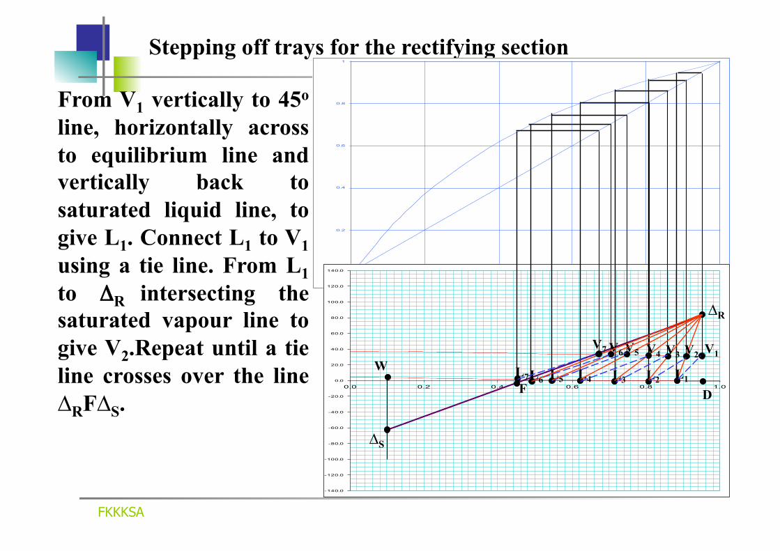
Stepping off trays for the rectifying section
From V1 vertically to 45o line, horizontally across to equilibrium line and vertically back to saturated liquid line, to give L1. Connect L1 to V1 using a tie line. From L1 to ΔR intersecting the saturated vapour line to give V2.Repeat until a tie line crosses over the line ∆RF∆S.
0
0.2
0.4
0.6
0.8
1
0 0.2 0.4 0.6 0.8 1
-140.0
-120.0
-100.0
-80.0
-60.0
-40.0
-20.0
0.0
20.0
40.0
60.0
80.0
100.0
120.0
140.0
0.0 0.2 0.4 0.6 0.8 1.0
∆S
∆R
D
V1 W
F
V2
L1 L2
V3
L3
V4
L4
V5
L5
V6
L6
V7
L7

FKKKSA
Stepping off trays for the stripping section
Draw a line from ∆S through L7 up to the saturated vapour line to give V8. From V8 vertically to 45o line, horizontally to equilibrium line and vertically back to saturated liquid line to give L8. Connect L8 and V8 using a tie line..Repeat until a tie line touches W or exceed W.
0
0.2
0.4
0.6
0.8
1
0 0.2 0.4 0.6 0.8 1
-140.0
-120.0
-100.0
-80.0
-60.0
-40.0
-20.0
0.0
20.0
40.0
60.0
80.0
100.0
120.0
140.0
0.0 0.2 0.4 0.6 0.8 1.0
∆S
∆R
D
V1 W
F
V2
L1 L2
V3
L3
V4
L4
V5 V6 V7
L7 L5 L6
V8
L8
V9
L9
V10
L10
V11
L11
V12
L12
No. of theoretical stages = no. of tie lines = 11.9 stages

FKKKSA
MINIMUM REFLUX RATIO, Rmin
-140.0
-120.0
-100.0
-80.0
-60.0
-40.0
-20.0
0.0
20.0
40.0
60.0
80.0
100.0
120.0
140.0
0.0 0.2 0.4 0.6 0.8 1.0
0
0.2
0.4
0.6
0.8
1
0 0.2 0.4 0.6 0.8 1
W
DF
Rmin occur when the line ∆RF∆S coincides with the tie line that passes through F
Get a tie line that passes through F and extend that line to intersect the vertical line xD to get ∆Rmin
∆Rmin
D1
1Rmin
D1
1min
CD
min hHHÄ
hH
HDQh
R =−
−+=

FKKKSA
MINIMUM STAGES, Nmin
-140.0
-120.0
-100.0
-80.0
-60.0
-40.0
-20.0
0.0
20.0
40.0
60.0
80.0
100.0
120.0
140.0
0.0 0.2 0.4 0.6 0.8 1.0
0
0.2
0.4
0.6
0.8
1
0 0.2 0.4 0.6 0.8 1
W
DF
Nmin is obtained when the operating lines are vertical since ΔR and ΔS are at infinity.
Nmin = 5.9 stages

FKKKSA
PARTIAL CONDENSER
Partial condenser = 1 stage
0
0.2
0.4
0.6
0.8
1
0 0.2 0.4 0.6 0.8 1
-140.0
-120.0
-100.0
-80.0
-60.0
-40.0
-20.0
0.0
20.0
40.0
60.0
80.0
100.0
120.0
140.0
0.0 0.2 0.4 0.6 0.8 1.0
∆S
∆R
VD W
F
V1
L0 L1
V2
L2
V3
L3
V4
L4
V5
L5
V6
L6
Distillate product, VD – vapour with the composition yD Condensed liquid/reflux, L0, have the composition xo which is in equilibrium with yD
yD
x0

FKKKSA
PARTIALLY VAPOURISED FEED,zF
-140.0
-120.0
-100.0
-80.0
-60.0
-40.0
-20.0
0.0
20.0
40.0
60.0
80.0
100.0
120.0
140.0
0.0 0.2 0.4 0.6 0.8 1.0
0
0.2
0.4
0.6
0.8
1
0 0.2 0.4 0.6 0.8 1
W
F with the composition zF lies on the tie line LF (composition = xF) and VF (composition = yF)
F
F
F
FFVFL
LV
=
F LF
VF
F LF
VF
By trial-and-error, locate the point F so as to satisfy the inverse lever rule: zF

FKKKSA
MULTICOMPONENT DISTILLATION
• more than 2 components
• shortcut calculation methods – an approximation
Equilibrium data • Raoult’s law – for ideal mixture
• hydrocarbon system:
AAA
A xPP
Ppy == B
BBB xP
PPpy == C
CCC xP
PPpy == D
DDD xP
PPpy ==
AAA xKy = BBB xKy = CCC xKy = DDD xKy =
where KA = vapour-liquid equilibrium constant or distribution coefficient
• relative volatility, αi :
€
αA = KAKref.
€
αB = KBKref.
€
αC = KCKref.
€
αD = KDKref.
• only allow separation between two components, heavy key and light key

FKKKSA
Example 11.7-2
F = 100 mol/h at boiling point at 405.3 kPa. xFA = 0.4, xFB = 0.25, xFC = 0.20 and xFD = 0.15 where components A = n-butane, B = n-pentane, C = n-hexane and D = n-heptane. 90% of B is recovered in the distillate and 90% of C in the bottoms. Calculate: (a) D and W moles/h (b) dew point of distillate and boiling point of bottoms (c) minimum stages for total reflux and distribution of other components in the distillate and bottoms. Solution:
1st trial: Assume all of component A will be in the distillate and all of component D will be in the bottom product
Components xF xFF yD yDD xW xWW A
B(L) C(H)
D
0.40 0.25 0.20 0.15
40.0 25.0 20.0 15.0
F=100
0.62 0.349 0.031
0 ∑yD=1.00
40.0 22.5 2.0 0
D=64.5
0 0.070 0.507 0.423
∑xW=1.00
0 2.5 18.0 15.0
W=35.5

Assume all A go to distillate and all D go to the bottoms. yAD(D)=xAF(F)=0.4(100)=40 mol/h xDW(W)=xDF(F)=0.15(100)=15 mol/h N-pentane(B): Light Key Overall Balance: F =D+W Comp Balance: xBF(F)=0.25(100)=25 mol/h=yBD(D) + xBW(W) Since 90% of B is in distillate: yBD(D) = (0.90)(25) = 22.5, xBW(W)=2.5 N-hexane (C): Heavy Key xCF(F)=0.20(100) =20 mol/h Since 90% of C is in the bottoms: xCW(W)=0.90(20)=18 mol/h, yCDD=2.0 mol/h

FKKKSA
DEW POINT For a vapour mixture of A, B, C and D:
Liquid composition which is in equilibrium with the vapour mixture:
€
xi =
yi
αi
yi
αi
∑
€
xi =yiKi
∑ = yi
Kref.
yiαi
∑ =1
1. By trial-&-error, assume Td.p.
2. Get corresponding values of Ki and αi
3. Calculate yi/αi
4. From Kref. = ∑(yi/αi) , get the corresponding T
5. Compare latest T with assumed T. If differ, use latest T for next iteration by repeating steps 2-4
6. Once Td.p. is obtained, calculate liquid composition

FKKKSA
Example 11.7-2
Dew point: Assume Td.p. = 67oC (Kref. = KC = ∑(yi/αi) = 0.26)
Components xF xFF yD yDD xW xWW A
B(L) C(H)
D
0.40 0.25 0.20 0.15
40.0 25.0 20.0 15.0
F=100
0.62 0.349 0.031
0 ∑yD=1.00
40.0 22.5 2.0 0
D=64.5
0 0.070 0.507 0.423
∑xW=1.00
0 2.5 18.0 15.0
W=35.5
Components yiD Ki αi yi /αi xi
A B(L) C(H)
D
0.62 0.349 0.031
0 ∑yiD=1.00
1.75 0.65 0.26 0.10
6.73 2.50 1.00
0.385
0.0921 0.1396 0.0310
0 ∑yi /αi=0.2627
0.351 0.531 0.118
0 ∑xi=1.00

FKKKSA
Example 11.7-2
1.75
0.65
0.26
0.10

FKKKSA
BOILING POINT
For a liquid mixture of A, B, C and D:
∑yi = ∑Kixi = K ref. ∑αixi = 1
Vapour composition which is in equilibrium with the liquid mixture:
€
yi =α
ix
i
αix
i
∑
1. By trial-&-error, assume Tb.p.
2. Get corresponding values of Ki and αi
3. Calculate αixi
4. From Kref. = 1/(αixi) , get the corresponding T
5. Compare latest T with assumed T. If differ, use latest T for next iteration by repeating steps 2-4
6. Once Tb.p. is obtained, calculate vapour composition

FKKKSA
Example 11.7-2
Boiling point: Assume Tb.p. = 132oC (Kref. = KC = 1/∑αixi = 1.144)
Components xF xFF yD yDD xW xWW A
B(L) C(H)
D
0.40 0.25 0.20 0.15
40.0 25.0 20.0 15.0
F=100
0.62 0.349 0.031
0 ∑yD=1.00
40.0 22.5 2.0 0
D=64.5
0 0.070 0.507 0.423
∑xW=1.00
0 2.5 18.0 15.0
W=35.5
Components xiw Ki αi xi αi yi A
B(L) C(H)
D
0 0.070 0.507 0.423
∑xW=1.00
4.95 2.34 1.10 0.61
5.00 2.043 1.000 0.530
0 0.1430 0.5070 0.2242
∑xi αi=0.8742 1/∑αixi = 1.144
0 0.164 0.580 0.256 ∑xi=1.00

FKKKSA
Example 11.7-2
5.00
2.35
1.15
0.61

FKKKSA
MINIMUM STAGES,NMIN AT R = ∞ Minimum stages, Nmin, using Fenske equation:
where:
α=
av, log
WxWx
DxDx
log
NL
LW
HW
HD
LD
min
xLD = mole fraction of LK in distillate
xLW = mole fraction of LK in bottom product xHD = mole fraction of HK in distillate
xHW = mole fraction of HK in bottom product
αLD = relative volatility of LK at dew point. αLW = relative volatility of LK at boiling point.
αL,av =
€
αLDαLW
Distribution of other components:
€
xiDDxiWW = (αi,av
)Nm xHDDxHWW

FKKKSA
Example 11.7-2
stages ltheoretica 5.4042.258 log
0.0700.507
0.031(0.349)log
av, log
WxWx
DxDx
log
NL
LW
HW
HD
LD
min ==α
=
αL,av =
€
αLDαLW = (2.50)(2.043) = 2.258
Components yiD=xiD yDD αi xiw xWW αi A
B(L) C(H)
D
0.62 0.349 0.031
0 ∑yD=1.00
40.0 22.5 2.0 0
D=64.5
6.73 2.50 1.00 0.385
0 0.070 0.507 0.423
∑xW=1.00
0 2.5
18.0 15.0
W=35.5
4.348 2.043 1.000 0.530
Distribution of other components:
€
xiDDxiWW = (αi,av
)Nm xHDDxHWW
Distribution of component A & D:
€
xADDxAWW = (αA,av
)Nm xHDDxHWW = (αA,av
)5.404 (0.031)64.5(0.507)35.5 = (αA,av
)5.4040.1111
€
xDDDxDWW = (αD,av
)Nm xHDDxHWW = (αD,av
)5.404 (0.031)64.5(0.507)35.5 = (αD,av
)5.4040.1111

FKKKSA
Example 11.7-2
αA,av =
€
αADαAW = (6.73)(4.348) = 5.409
αD,av =
€
αDDαDW = 0.385(0.530) = 0.452
€
xADDxAWW = (αA,av
)Nm xHDDxHWW = (αA,av
)5.404 (0.031)64.5(0.507)35.5 = (5.409)5.4040.1111=1017
€
xDDDxDWW = (αD,av
)Nm xHDDxHWW = (αD,av
)5.404 (0.031)64.5(0.507)35.5 = (0.452)5.4040.1111= 0.001521
Material balance of component A & D:
Components yiD=xiD yDD αi xiw xWW αi A
B(L) C(H)
D
0.62 0.349 0.031
0 ∑yD=1.00
40.0 22.5 2.0 0
D=64.5
6.73 2.50 1.00 0.385
0 0.070 0.507 0.423
∑xW=1.00
0 2.5
18.0 15.0
W=35.5
4.348 2.043 1.000 0.530
40 Wx Dx AWAD =+ 15 Wx Dx DWDD =+
Solving : 0.039Wx39.961 Dx
AW
AD==
14.977Wx0.023 Dx
DW
DD==

FKKKSA
Example 11.7-2
Revised distillate and bottoms compositions:
Components xF xFF yD yDD xW xWW A
B(L) C(H)
D
0.40 0.25 0.20 0.15
40.0 25.0 20.0 15.0
F=100
0.62 0.349 0.031
0 ∑yD=1.00
40.0 22.5 2.0 0
D=64.5
0 0.070 0.507 0.423
∑xW=1.00
0 2.5 18.0 15.0
W=35.5
Components xF xFF yD yDD xW xWW A
B(L) C(H)
D
0.40 0.25 0.20 0.15
40.0 25.0 20.0 15.0
F=100
0.6197 0.3489 0.0310 0.0004 ∑yD=1.00
39.961 22.5 2.0
0.023 D=64.484
0.0011 0.0704 0.5068 0.4217 ∑xW=1.00
0.039 2.500 18.00 14.977
W=35.516

FKKKSA
MINIMUM REFLUX RATIO,RMIN Underwood’s shortcut method for calculating Rmin:
where: xiD = mole fraction of component i in distillate taken at R = ∞
xiF = mole fraction of component i in the feed
αi = relative volatility of the top and the bottom of the tower
To determine Rmin: 1. By trial-and-error, assume θ ( αLK 〈 θ 〉 αHK )
€
1−q= αixiFαi−θ
∑
€
Rm +1= αixiDαi−θ
∑
2. Calculate 1-q for various θ
3. Use θ obtained to calculate Rmin
Assumes constant flows in both sections of tower
Uses constant average α (at Tave. = [Ttop + Tbottom ]/2)

Example 11.7-3
Using the conditions and results given in Example 11.7-2, calculate the following:
(a) Minimum reflux ratio using the Underwood method.
(b) Number of theoretical stages at an operating reflux ratio R of 1.5Rm using the Erbar-Maddox correlation.
(c) Location of feed tray using the method of Kirkbride.

FKKKSA
Example 11.7-3
Tb.p. = 132oC & Tdp = 67oC Tave. = (132 + 67)oC/2 = 99.5oC
Components xF xFF xiD xiDD xW xWW A
B(L) C(H)
D
0.40 0.25 0.20 0.15
40.0 25.0 20.0 15.0
F=100
0.6197 0.3489 0.0310 0.0004 ∑yD=1.00
39.961 22.5 2.0
0.023 D=64.484
0.0011 0.0704 0.5068 0.4217 ∑xW=1.00
0.039 2.500 18.00 14.977
W=35.516
Components xiF xiD Ki αi xiW A
B(L) C(H)
D
0.40 0.25 0.20 0.15
∑xiF=1.00
0.6197 0.3489 0.0310 0.0004 ∑yD=1.00
3.12 1.38 0.60 0.28
5.20 2.30 1.00 0.467
0.0011 0.0704 0.5068 0.4217
∑xiW=1.00

FKKKSA
Example 11.7-3
3.12
1.38
o.60
0.28

FKKKSA
Example 11.7-3
Components xiF xiD Ki (99.5oC) αi (99.5oC) xiW
A B(L) C(H)
D
0.40 0.25 0.20 0.15
∑xiF=1.00
0.6197 0.3489 0.0310 0.0004 ∑yD=1.00
3.12 1.38 0.60 0.28
5.20 2.30 1.00 0.467
0.0011 0.0704 0.5068 0.4217
∑xiW=1.00
€
1−q= αixiFαi−θ
∑ = 1−0=1= 5.2(0.4)5.20−θ
+ 2.3(0.25)
2.3−θ
+ 1.0(0.2)
1.0−θ
+ 0.467(0.15)
0.467−θ
1. By trial-and-error, assume θ ( αLK 〈 θ 〉 αHK )
θ (assumed)
∑(sum)
1.210 1.200
1.2096
0.5213 0.5200 0.5213
0.5275 0.5227 0.5273
-0.9524 -1.0000 -0.9542
-0.0942 -0.0955 -0.0943
+0.0022 -0.0528 +0.0001
€
0.467(0.15)0.467−θ
€
1.0(0.2)1.0−θ
€
2.3(0.25)2.3−θ
€
5.2(0.4)5.20−θ
2. Calculate 1-q for various θ

FKKKSA
Example 11.7-3
Components xiF xiD Ki (99.5oC) αi (99.5oC) xiW
A B(L) C(H)
D
0.40 0.25 0.20 0.15
∑xiF=1.00
0.6197 0.3489 0.0310 0.0004 ∑yD=1.00
3.12 1.38 0.60 0.28
5.20 2.30 1.00 0.467
0.0011 0.0704 0.5068 0.4217
∑xiW=1.00
θ = 1.2096
€
Rm +1= αixiDαi−θ
∑ = 5.20(0.6197)5.20−1.2096+ 2.30(0.3489)
2.30−1.2096+1.00(0.0310)1.00−1.2096+ 0.467(0.15)
0.467−1.2096
3. Use θ obtained to calculate Rmin
€
Rm +1= αixiDαi−θ
∑ =1.395
Rmin = 0.395

FKKKSA
SHORTCUT METHOD NUMBER OF STAGES
Correlation of Erbar & Maddox:
Feed plate location using Kirkbride method:
where:
Ne = number of theoretical stages above the feed plate
NS = number of theoretical stages below the feed plate
=
2
HD
LW
LF
HF
xx
DW
xx
log 0.206sNeN
log

FKKKSA
Example 11.7-3
R = 1.5Rmin = 1.5(0.395) = 0.593
R/(R+1) = 0.593/(0.593+1) = 0.3723
Rmin/(Rmin+1) = 0.395/(0.395+1)
0.37
0.49
Nmin/N = 0.49 = 5.404/N
N = 11.0 theoretical stages or 10 theoretical trays plus a reboiler
Rmin/(Rmin+1) = 0.2832

FKKKSA
Example 11.7-3
N = 11.0 theoretical stages Ne + NS = 11.0 theoretical stages
=
2
HD
LW
LF
HF
xx
DW
xx
log 0.206sNeN
log
0.073440.03100.0704
64.48435.516
0.250.2 log 0.206
sNeN
log2
==
Components xiF (F=100 mol/h) xiD (D=64.484 mol/h) xiW (W=35.516 mol/h)
A B(L) C(H)
D
0.40 0.25 0.20 0.15
∑xiF=1.00
0.6197 0.3489 0.0310 0.0004 ∑yD=1.00
0.0011 0.0704 0.5068 0.4217
∑xiW=1.00
1.184 sNeN= s1.184N eN = 1.184NS + NS = 11.0
NS = 5.0 Ne = 6.0 Feed tray = 6.0 trays from the top