Senior Design Summer 2008 Presentation
89
EGR 400: Senior Design I Final Report Presentation Summer 2008 2009 Frame Front Rev B.
-
Upload
nickpartenope -
Category
Documents
-
view
1.353 -
download
0
Transcript of Senior Design Summer 2008 Presentation
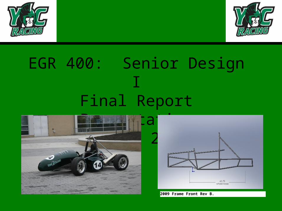
EGR 400: Senior Design IFinal Report Presentation
Summer 2008
2009 Frame Front Rev B.

Introduction
• Objective– Design, build, and compete with a
small, formula style, race car.
• Plan– Divide into four teams:
• Frame and Suspension• Brakes and Controls• Engine and Drive Train• Body and Miscellaneous
– Work in sub-groups as well as collectively with the entire class.
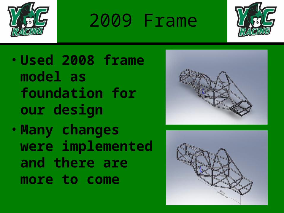
2009 Frame
• Used 2008 frame model as foundation for our design
• Many changes were implemented and there are more to come
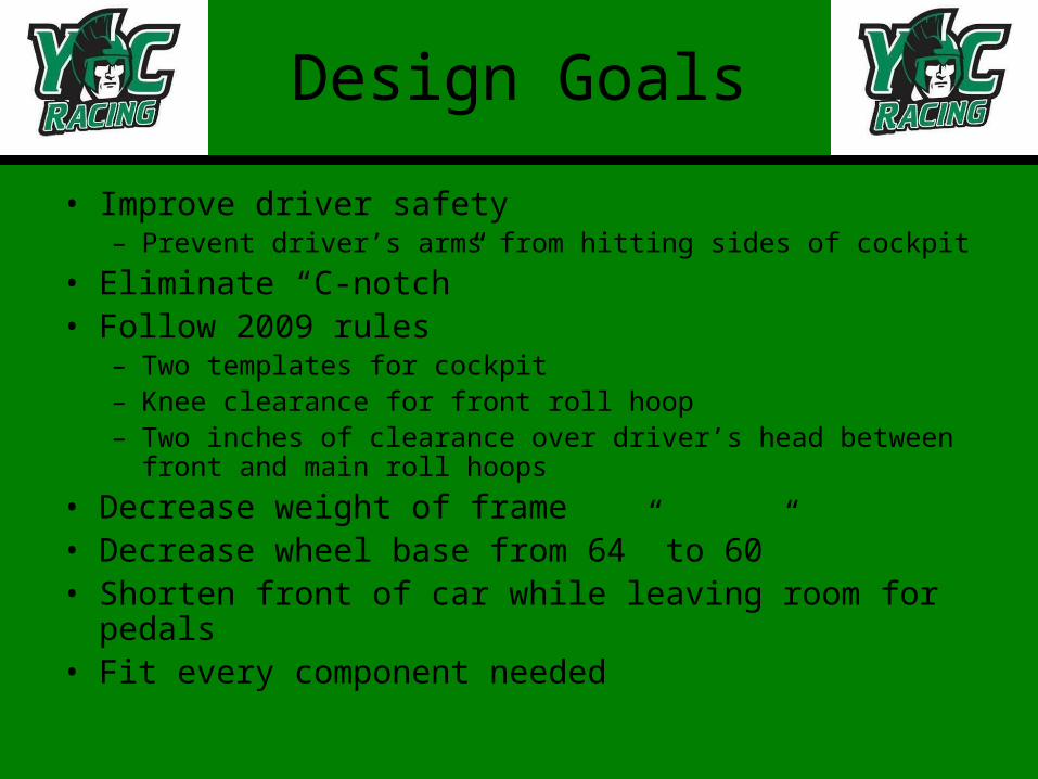
Design Goals
• Improve driver safety– Prevent driver’s arms from hitting sides of cockpit
• Eliminate “C-notch”• Follow 2009 rules
– Two templates for cockpit– Knee clearance for front roll hoop– Two inches of clearance over driver’s head between front and
main roll hoops
• Decrease weight of frame• Decrease wheel base from 64” to 60”• Shorten front of car while leaving room for pedals• Fit every component needed

Benchmarks in the road we’ve traveled
• June 22: build prototype frame out of MDF
• Week of June 23: learn how to manipulate 2008 frame model
• Week of July 24: make 2 different revisions of the model to compare concepts
• Week of July 28: receive final front and rear suspension points from suspension team
• August 6: selection revision B as design
Prototype Goals
• Elbow clearance
• Foot pedal positions
• Height of roll hoops
• Line of sight
• Angle of drivers seat
• Adjustable for changes
• Steering wheel mounting
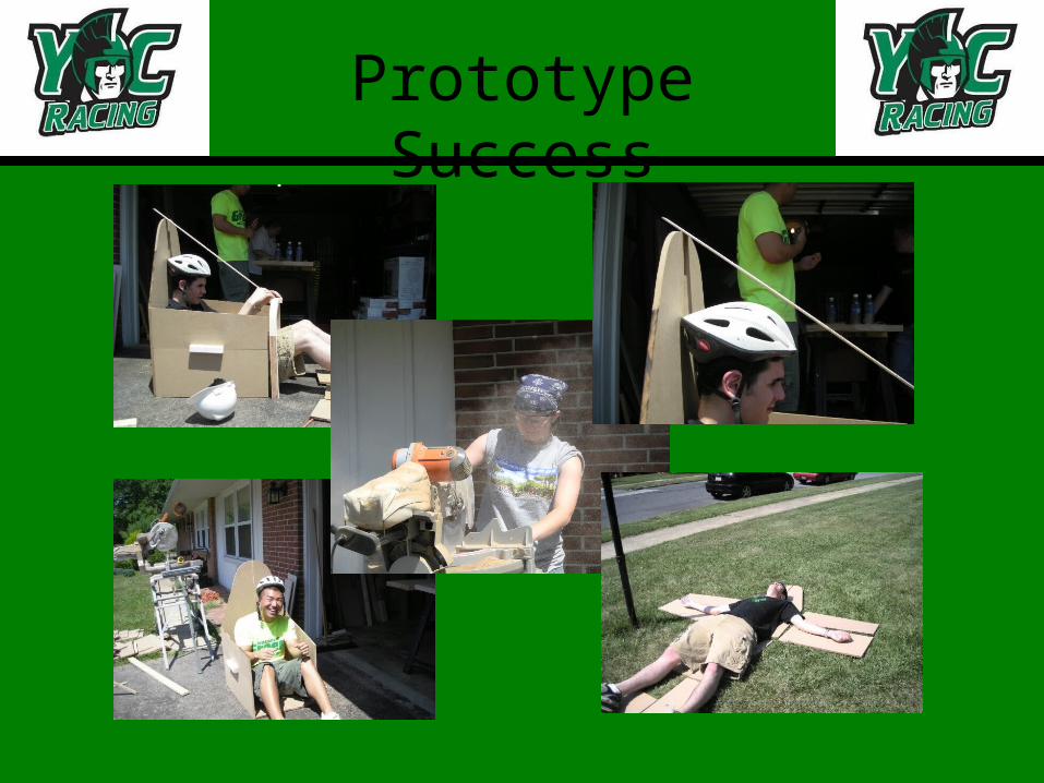
Prototype Success
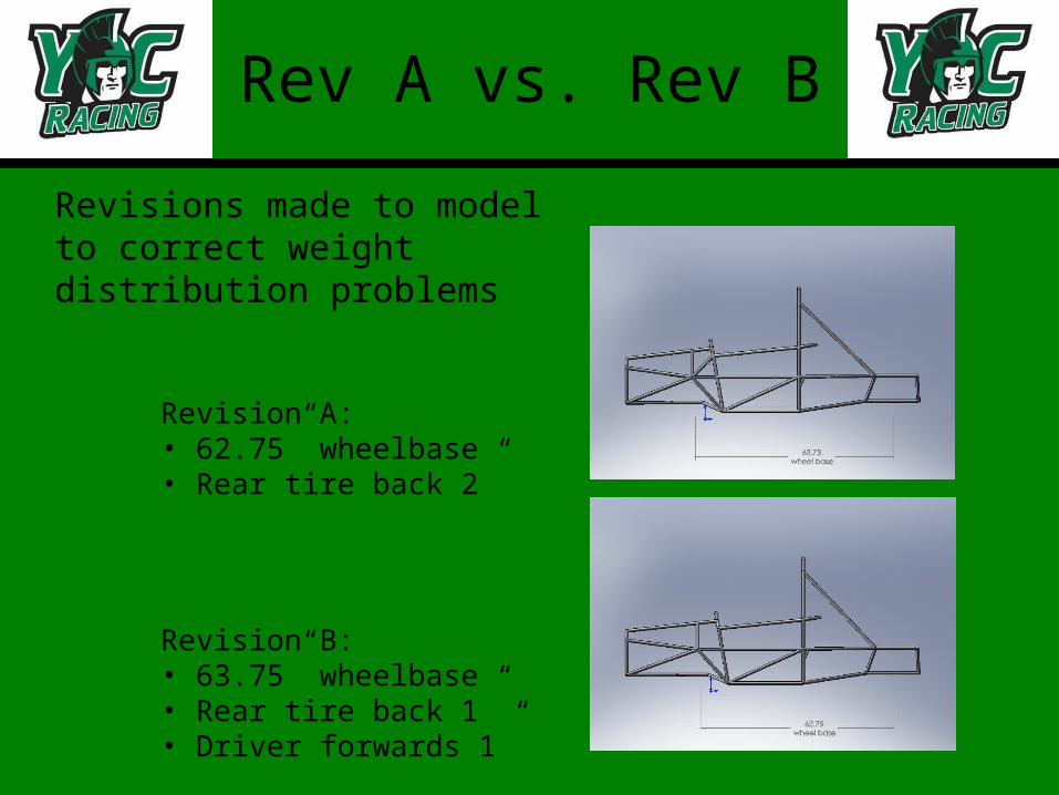
Rev A vs. Rev B
Revisions made to model to correct weight distribution problems
Revision A: • 62.75” wheelbase• Rear tire back 2”
Revision B:• 63.75” wheelbase• Rear tire back 1”• Driver forwards 1”
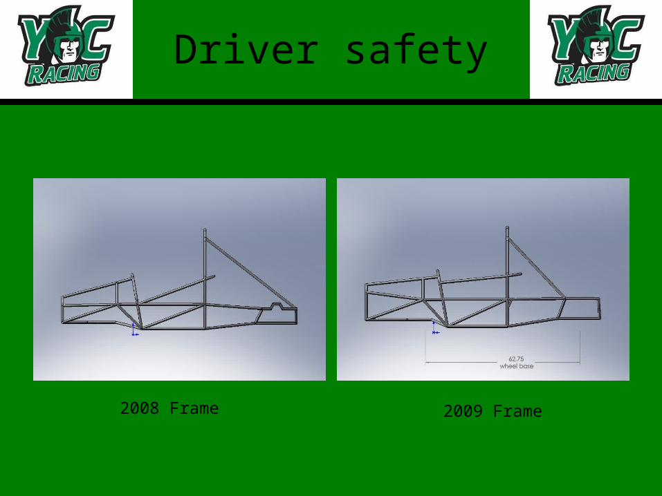
Driver safety
2008 Frame 2009 Frame
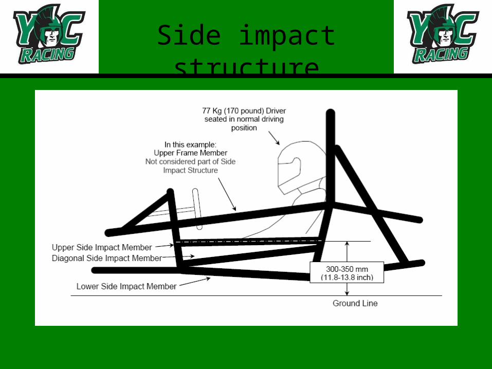
Side impact structure
C-notch
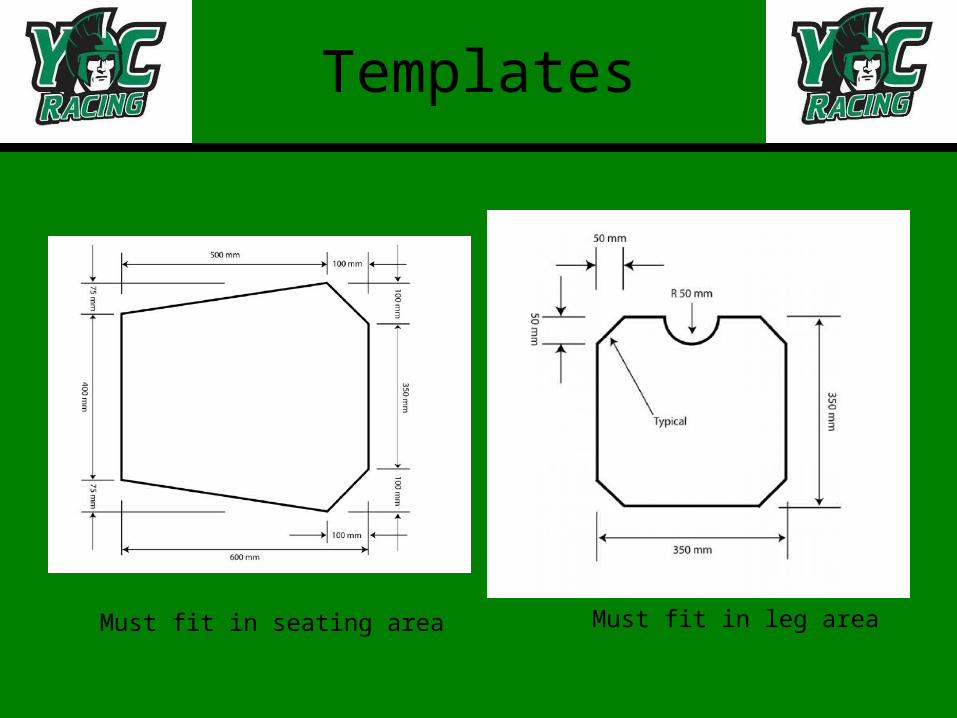
Templates
Must fit in seating area Must fit in leg area
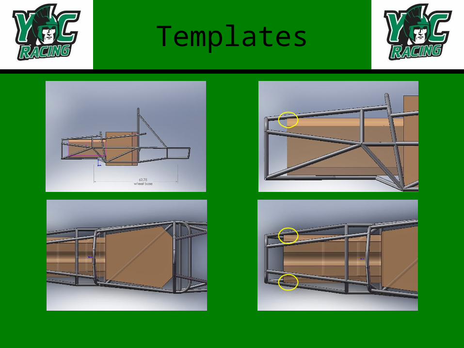
Templates
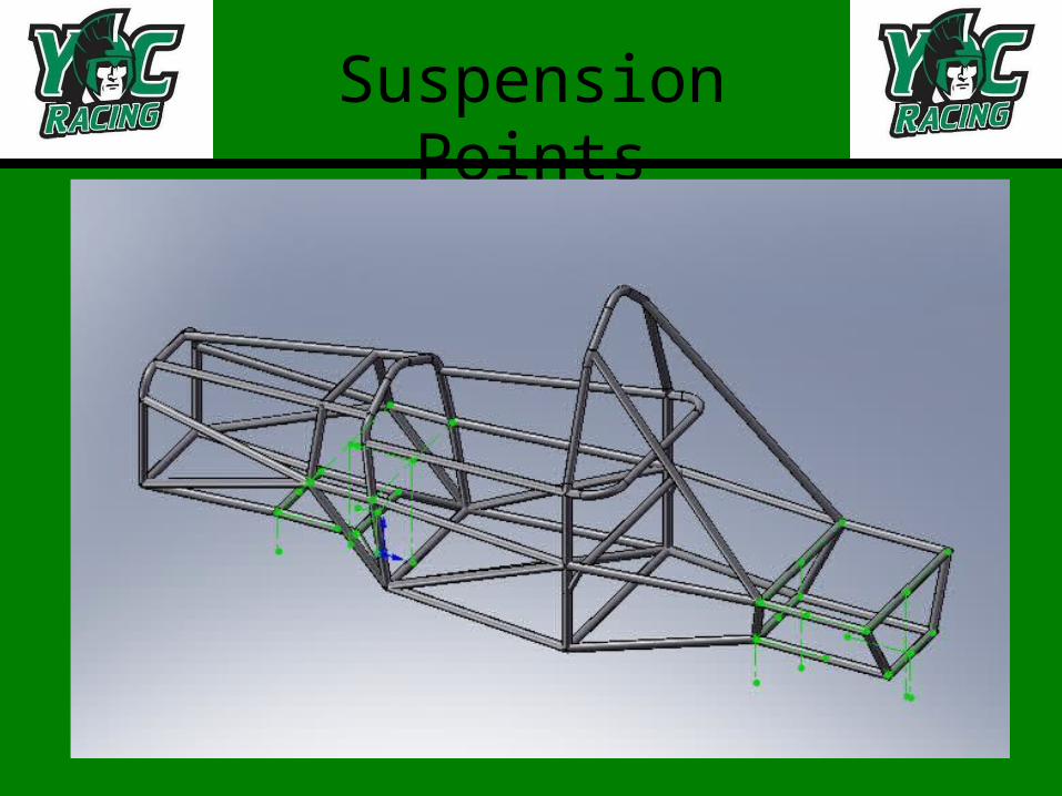
Suspension Points

Interaction withengine team
• Met with engine team • Engine compartment
has approximately equal room to 2008 car, space won’t be an issue
• Engine mounts will be added to the model after they are designed

FEA withCosmosWorks
Material Properties
• Material properties obtained from MatWeb.
• Custom material created in SolidWorks.
• Material Properties:– Sut = 128 ksi
– Sy = 113 ksi
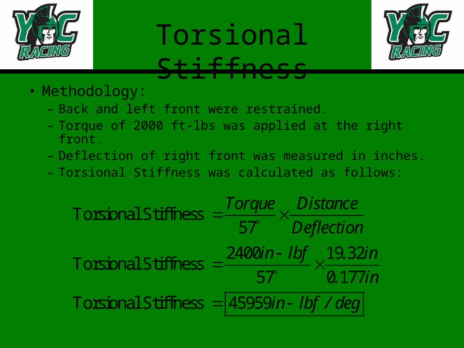
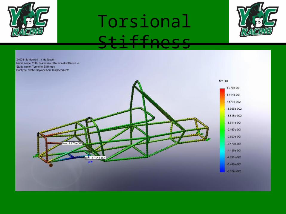
Torsional Stiffness
• Methodology:– Back and left front were restrained.– Torque of 2000 ft-lbs was applied at the right front.– Deflection of right front was measured in inches.– Torsional Stiffness was calculated as follows:
Torsional Stiffness 57
2400 19 32Torsional Stiffness
57 0 177
Torsional Stiffness 45959
Torque Distance
Deflection
in lbf . in
. in
in lbf / deg
Torsional Stiffness
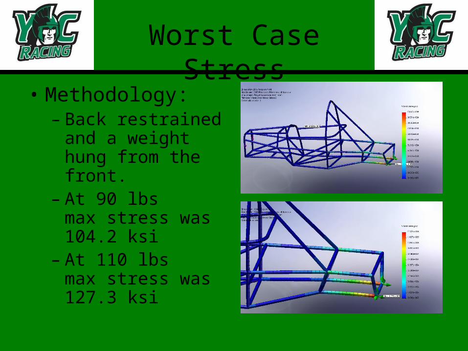
Worst Case Stress
• Methodology:– Back restrained
and a weight hung from the front.
– At 90 lbs max stress was 104.2 ksi
– At 110 lbs max stress was 127.3 ksi
Case 1 Suspension
• Methodology– Force vectors for the three main scenarios
were obtained from the suspension team.– Force vectors were applied to each of the 16
suspension points.– The rear was restrained.
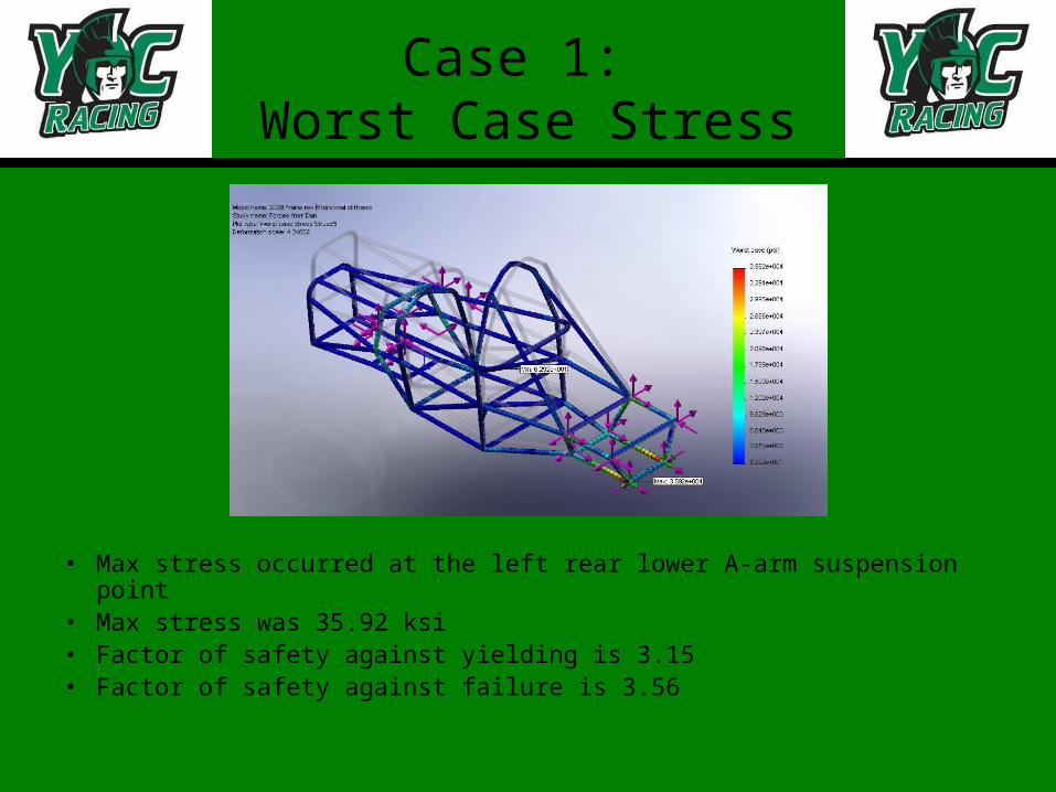
Case 1: Worst Case Stress
• Max stress occurred at the left rear lower A-arm suspension point• Max stress was 35.92 ksi• Factor of safety against yielding is 3.15• Factor of safety against failure is 3.56
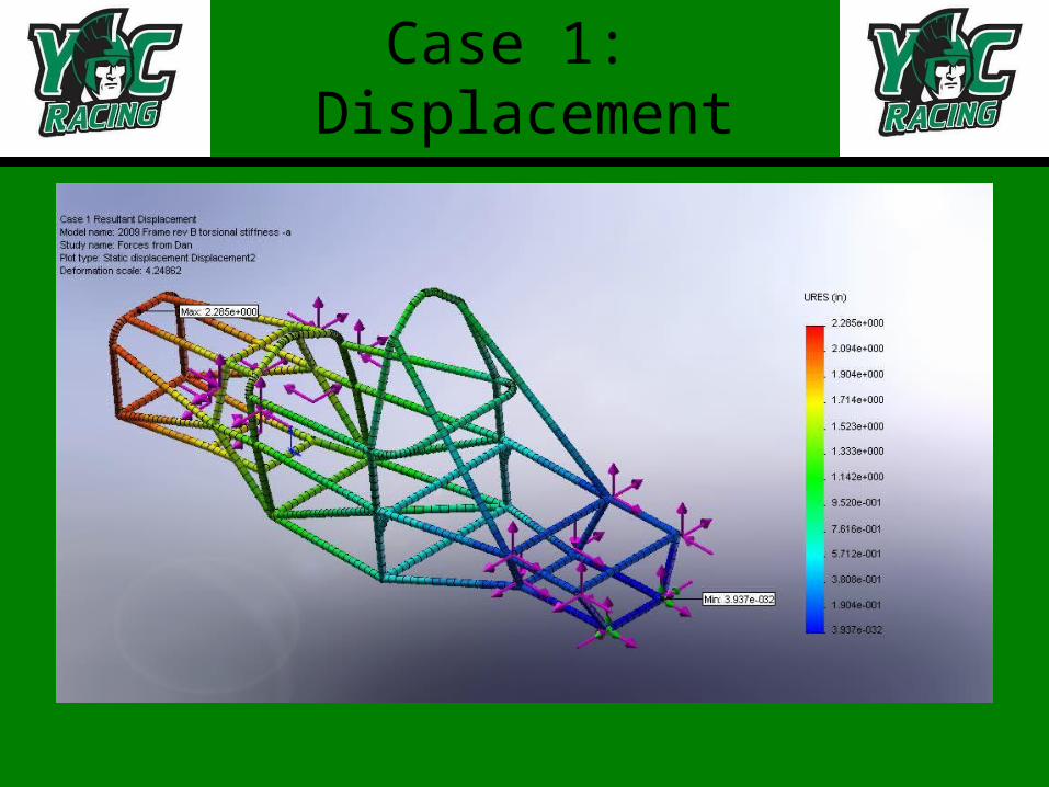
Case 1: Displacement

Case 1: Bending Stress
• Max stress occurred at the right rear A-arm front suspension point• Max stress was 14.37 ksi• Factor of safety against yielding is 7.86• Factor of safety against failure is 8.91

FEA w/ ANSYS

Prepping the model

Creating the Mesh
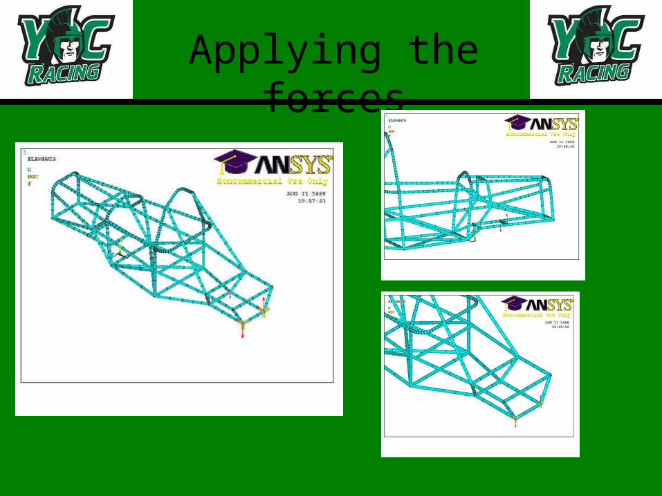
Applying the forces

Results
What’s Next?
• Analysis needs to be completed for case 2 and case 3.
• Results from ANSYS analysis need to be compared.
• Anticipate similar results.
Conclusions from FEA
We have a frame that will meet or exceed all the physical requirements.

Changes Planned
• Main roll hoop – Radii of bends– Height
• Front roll hoop– Radii of bends– Number of bends
• Main roll hoop bracing• Front suspension point member• Shoulder harness and back brace• Add gussets for shoulder harness and back brace • Engine mounts
Engine Sensors
• Sensors– Throttle Position– Air Temperature– Water Temperature– Crank Position
• Each sensor delivers feedback to the ECU
• Plan to add a Manifold Absolute Pressure sensor.

Engine Tuning
• Goals– Began with acquiring a FSAE 4cly. Engine
map from Performance Electronics.– Read the tuning manual for the ECU to
understand the different parameters of the engine
– Engine started– Tune engine
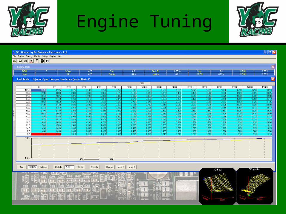
Engine Tuning

Engine Tuning
• We tuned the engine– Real World– Stand testing
• The fuel map is tuned to be the correct ratio
• Spark map was left alone because that has more chance of damaging the engine
Engine Goals
• Acceleration and Deceleration compensations need more tuning
• Re-tune the fuel and spark maps once the MAP sensor is installed
• Also, need re-tune for our intake and exhaust designs
• Swap engines with 2008 FSAE car
Drive Train: Goals
• Improve upon current design– Lighter/smaller
differential
• Account for torque steer and misaligned sprocket
• Improve acceleration– Gear ratio– Larger rear sprocket
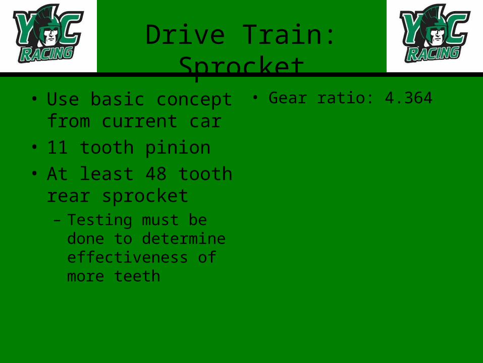
Drive Train: Sprocket
• Use basic concept from current car
• 11 tooth pinion• At least 48 tooth rear
sprocket– Testing must be done
to determine effectiveness of more teeth
• Gear ratio: 4.364

Drive Train: Differential
• Design choices:
– Honda ATV diff.
– Audi diff. (2007 FSAE)
– Miata diff. (2008 FSAE)
– New diff.
• Considerations:
– Ease of adaptation
– Weight
– Simplicity

Drive Train- Axles
Sprocket misalignment
• Solution/Alternatives– Center the differential
• Multi-stage gear• Larger differential housing
– Use different diameter axles– Provide calculations to prove design choices
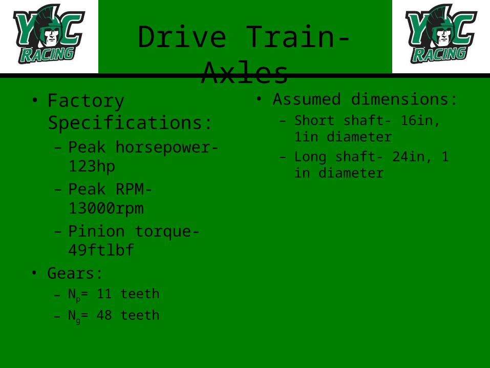
Drive Train- Axles
• Factory Specifications:– Peak horsepower-
123hp– Peak RPM- 13000rpm– Pinion torque- 49ftlbf
• Gears:– Np= 11 teeth
– Ng= 48 teeth
• Assumed dimensions:– Short shaft- 16in, 1in
diameter– Long shaft- 24in, 1 in
diameter
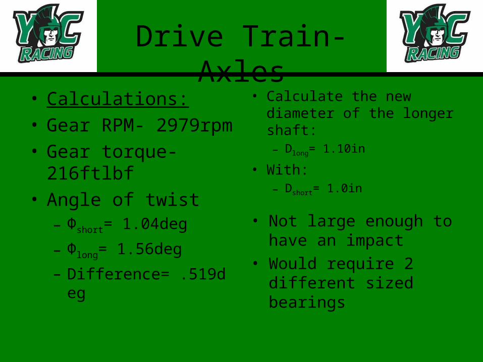
Drive Train- Axles
• Calculations:• Gear RPM- 2979rpm• Gear torque- 216ftlbf• Angle of twist
– Φshort= 1.04deg
– Φlong= 1.56deg
– Difference= .519deg
• Calculate the new diameter of the longer shaft:– Dlong= 1.10in
• With:– Dshort= 1.0in
• Not large enough to have an impact
• Would require 2 different sized bearings

Intake
• Philosophy
• Components of Intake
• Calculations
• Preliminary Design
• Future Plans
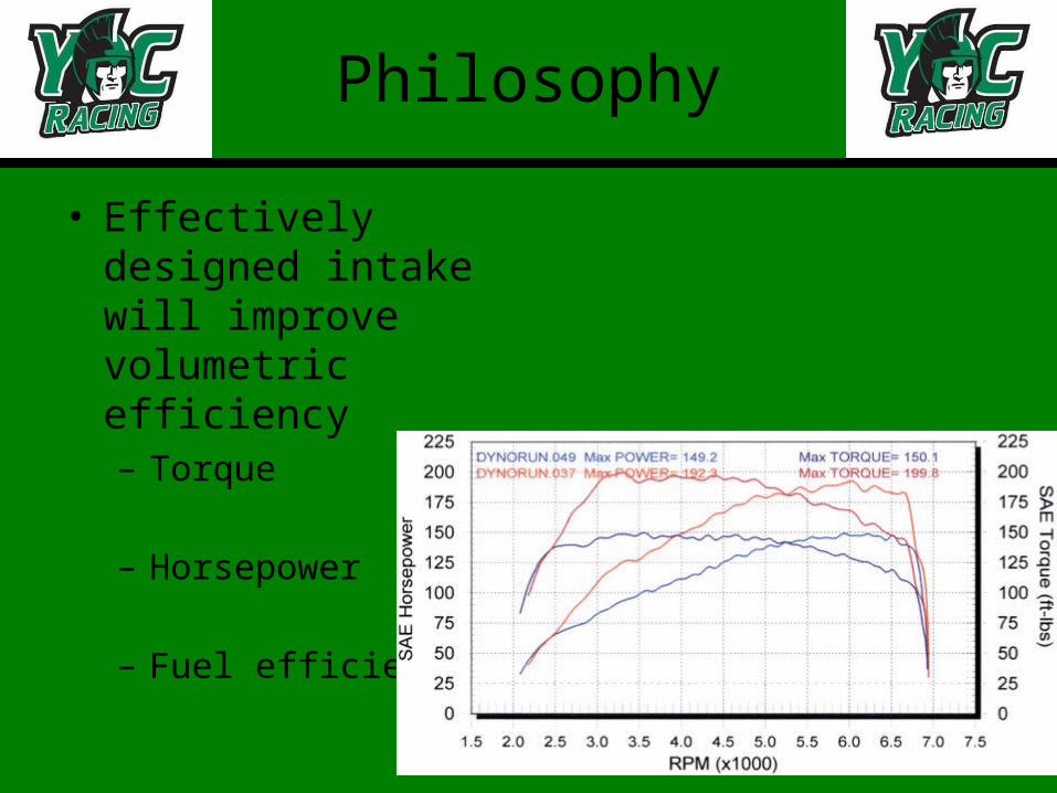
Philosophy
• Effectively designed intake will improve volumetric efficiency– Torque
– Horsepower
– Fuel efficiency
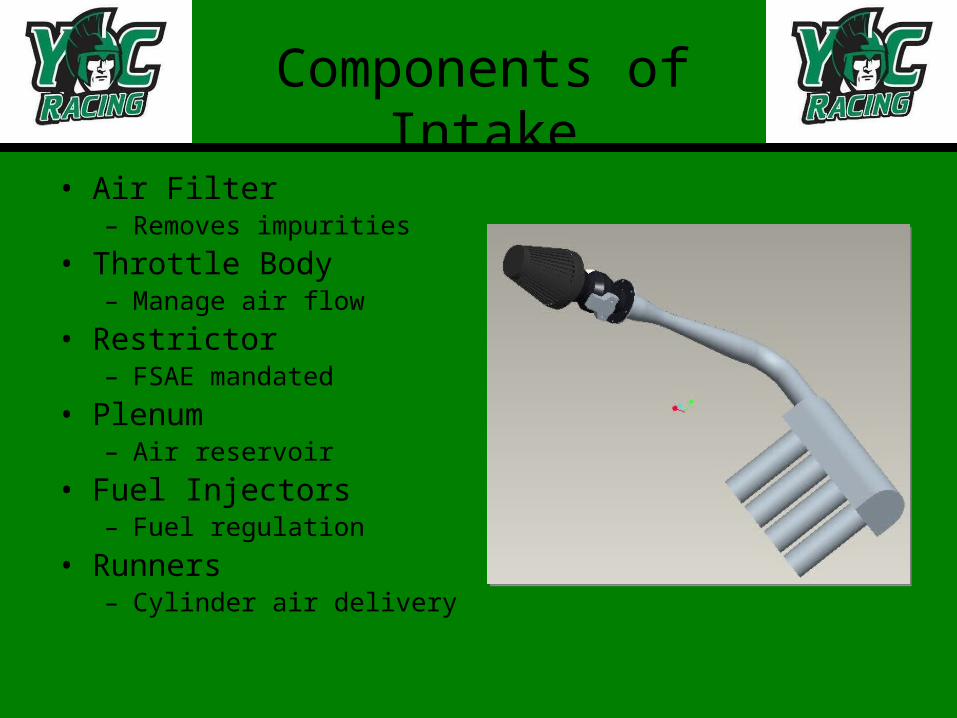
Components of Intake
• Air Filter– Removes impurities
• Throttle Body– Manage air flow
• Restrictor– FSAE mandated
• Plenum– Air reservoir
• Fuel Injectors– Fuel regulation
• Runners– Cylinder air delivery

Restrictor
• 20mm Venturi Restrictor
• Placed after throttle body
• Severely limits air flow

Restrictor
D 35 mm
L1 35 mm
R1 48.125 mm
α1 21 Degrees
R2 72.5 mm
Dt 20 mm
L3 6.67 mm
R3 100 mm
α2 7 Degrees
R4 100 mm
L5 35 mm

Plenum
• Smooth out turbulence
• Even flow distribution
• 4-6X engine displacement– 3000cc
• Shape not yet determined

Runners
• Employed resonance equations– Ltotal=18”
• Primary tuning peak=5000 RPM– Helmholtz peak=7500 RPM– Helmholtz peak=11250 RPM

Preliminary Design
• Overhead Entrance– Straight delivery=Minimal flow loss– Easier construction
• Side Entrance– More bends=More flow loss– More difficult construction
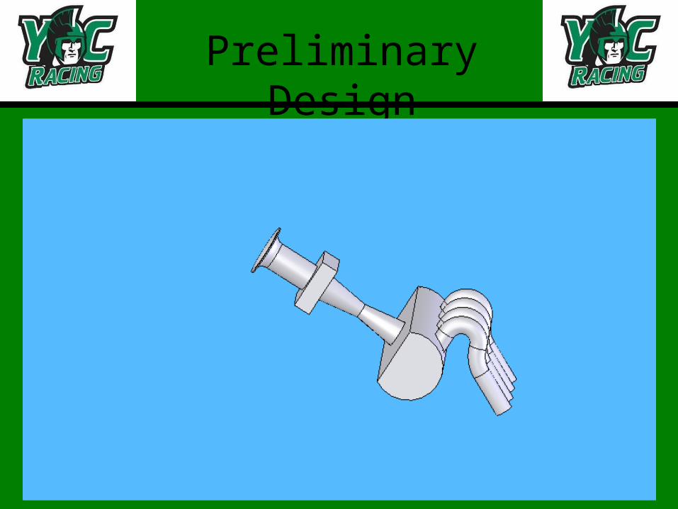
Preliminary Design
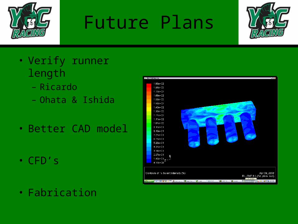
Future Plans
• Verify runner length– Ricardo – Ohata & Ishida
• Better CAD model
• CFD’s
• Fabrication

Exhaust Design Overview
• Components
• Header Design Considerations
• Selected design
• Muffler design Considerations
• Selected Muffler
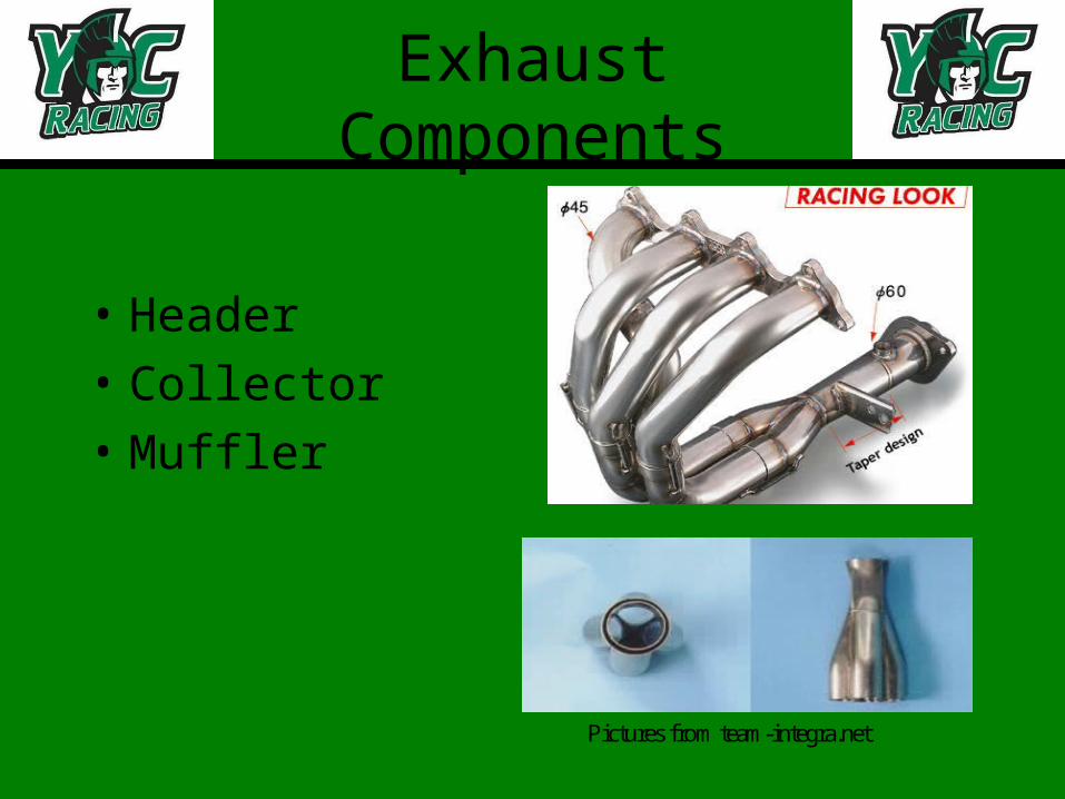
Exhaust Components
• Header
• Collector
• Muffler
Pictures from team-integra.net
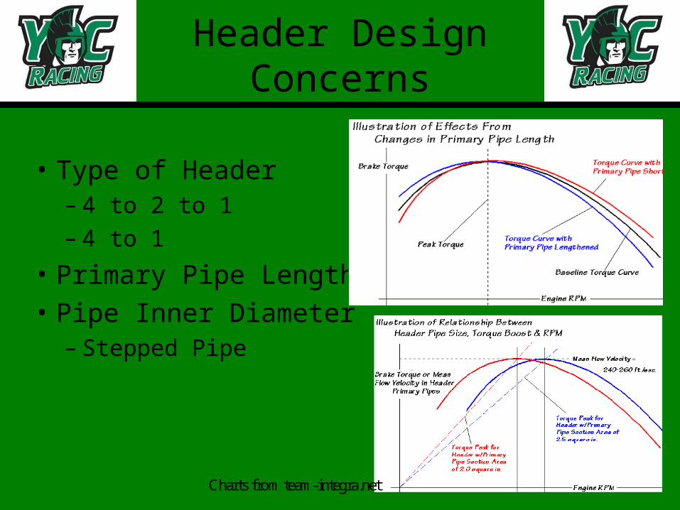
Header Design Concerns
• Type of Header– 4 to 2 to 1– 4 to 1
• Primary Pipe Length
• Pipe Inner Diameter– Stepped Pipe
Charts from team-integra.net
Header Design
• Competition Requirements
• Final Design – Primary Pipe Length– Pipe Diameter – Collector

Muffler Design Concerns
• Muffler Types– Resonance– Absorptive– Back Pressure
• Materials– Titanium– Stainless Steel– Carbon Fiber
Picture from Motor cycle superstore .com
Pictures from starcycle-usa.com
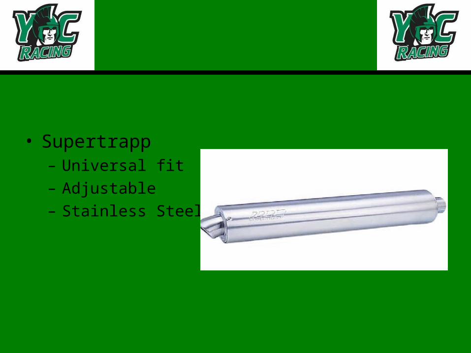
• Supertrapp– Universal fit– Adjustable– Stainless Steel
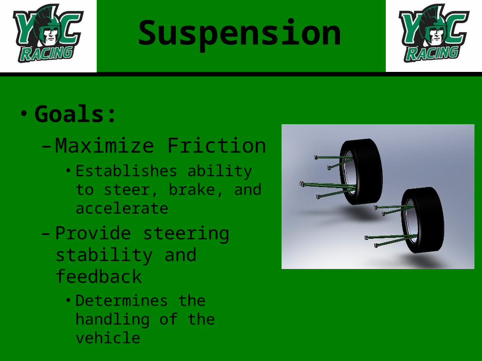
Suspension
• Goals: – Maximize Friction
• Establishes ability to steer, brake, and accelerate
– Provide steering stability and feedback
• Determines the handling of the vehicle

SuspensionGeometry
• King Pin Inclination– 2.5°
• Helps with packaging• Provides steering
feedback• Increases steering
effort
• Scrub Radius– .75”
• Similar effects as KPI

Suspension Geometry
• Static Camber– Front: -1°, Rear: -.5°
• Negative camber maximizes the size of the tire patch
• Caster– 4°
• Provides beneficial camber gain during steering
• Increases steering effort

Front View Geometry
• Solidworks/Excel– Parameters set in
Excel and imported into Solidworks
• Solidworks used to cycle suspension through range of motion
– Results graphed in Excel

Camber Curves

Stress Analysis
• Excel sheet used to find wheel loads
• MathCAD file used to find forces in each member
• Excel sheet used to calculate safety factors in tension, compression, and buckling

Suspension Dynamics: Tire Behavior
• Slip angle• Cornering force
curve• Pneumatic trail• Aligning torque• Steering torque
Cornering Force vs. Slip Angle: Avon 1.0/20.0-13, 1 deg Camber
-5
-4
-3
-2
-10
1
2
3
4
5
Slip Angle (deg)
Cor
neri
ng F
orce
(kN
)
'
350 kg
250 kg
150 kg
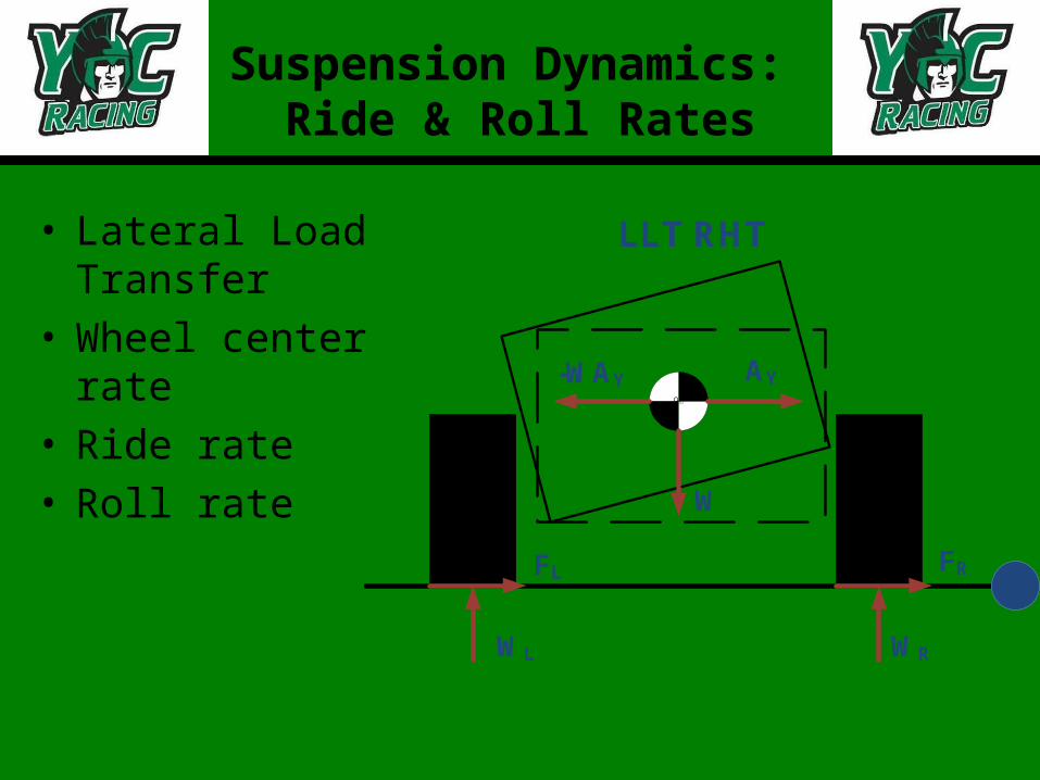
Suspension Dynamics: Ride & Roll Rates
• Lateral Load Transfer
• Wheel center rate• Ride rate• Roll rate
90909090
LLT RHT
WRWL
FL FR
W
-WAY AY
• Worst case scenario:– Critical speed at tightest turn
• Weight & CG Assumptions
• Iterative design process
• Preliminary results– Roll gradient & body roll angle– Wheel, spring & anti-roll bar rates– Slip angle, aligning torque & steering torque
Suspension Dynamics: Ride & Roll Rate Calculations

• Pull rod vs. push rod– Lower CG & reduce weight
• Rocker arm– Installation ratio of 1: increased sensitivity
• Anti-roll bar– Blades: increased adjustability
• Shocks– 1’’ jounce, 1’’ rebound
Suspension Linkage Design Overview

Suspension Linkage Design Overview II

Suspension Linkage Design Overview III
Pull Rod
Rocker ArmAnti-Roll Bar
Blade
Shock/Spring
Suspension Linkage Motion Visualization
Upward Motion due to Vertical Wheel Displacement
RotationJounce/Compression
Bending
Torsion
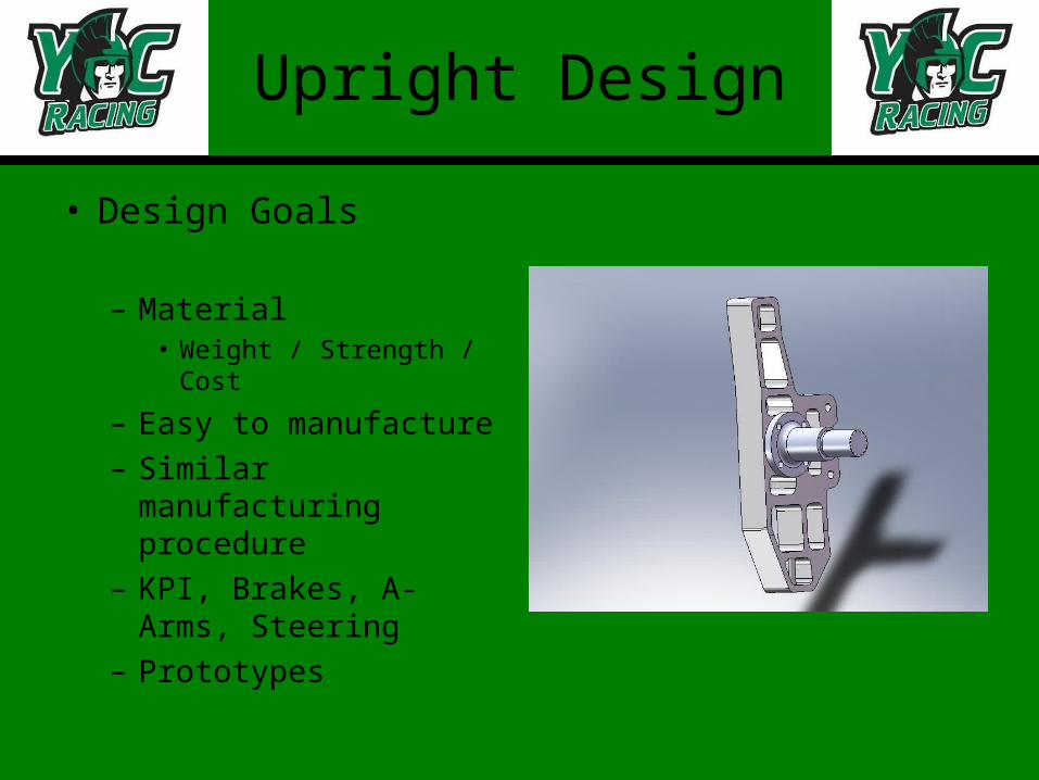
Upright Design
• Design Goals
– Material• Weight / Strength / Cost
– Easy to manufacture– Similar manufacturing
procedure– KPI, Brakes, A-Arms,
Steering– Prototypes
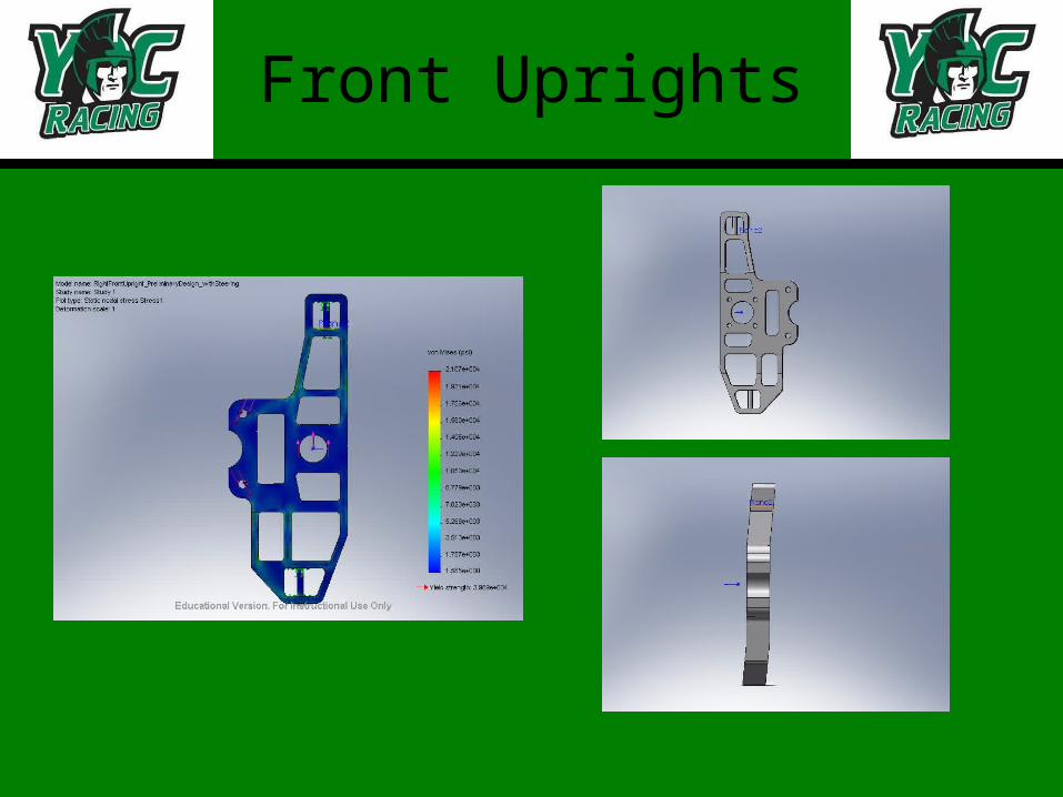
Front Uprights
Rear Uprights
• Design Goals
– Interchangeable– Lightweight– Design Considerations
• A-arms• Tie-Rod• Bearing

Steering
• Design Goals
– No > 180º for any turn– 60º - 80º steer = 9.5m turn– Ratio for manageable steer– Rack total travel ≤ stock
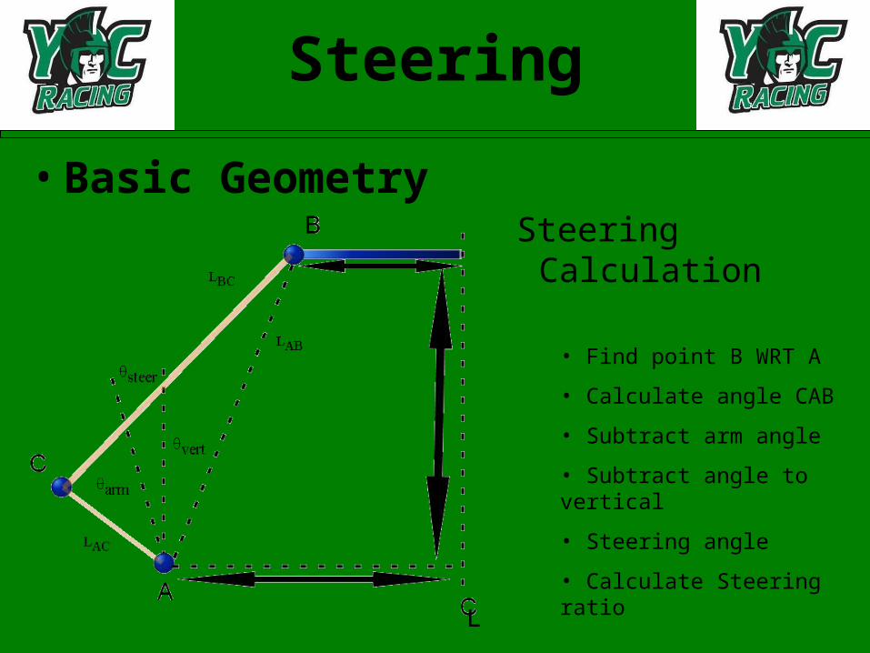
Steering
• Basic GeometrySteering Calculation
• Find point B WRT A
• Calculate angle CAB
• Subtract arm angle
• Subtract angle to vertical
• Steering angle
• Calculate Steering ratio
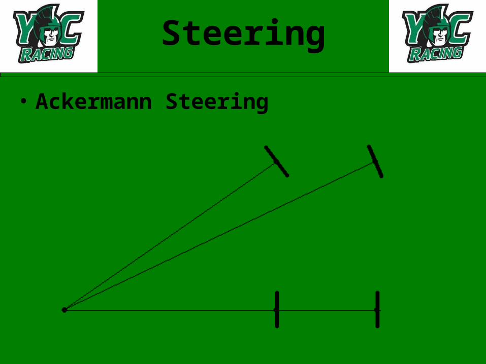
Steering
• Ackermann Steering
Brakes
• Design Goals
– Max pedal force < 100lbf – No lock < 60lbf pedal force– Lock front wheels first– Built-in Bias– Light, Compact, Inexpensive

Brakes
• System Layout
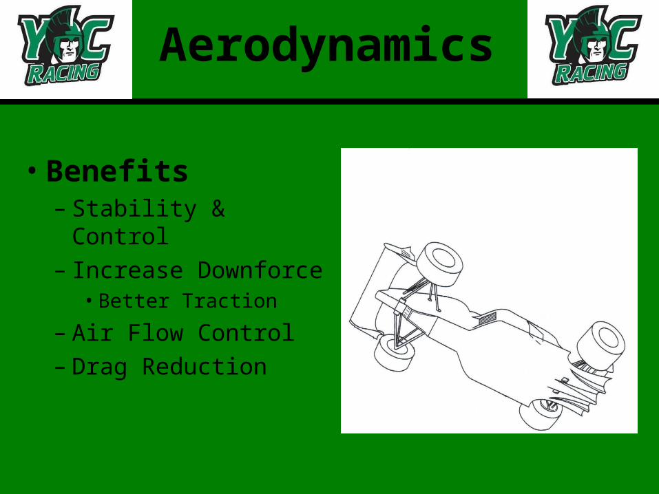
Aerodynamics
• Benefits– Stability & Control– Increase Downforce
• Better Traction
– Air Flow Control– Drag Reduction
Aerodynamics
• Drag Components– Basic External Shape
• Less than Perfect Shape• Interference
– Internal Flow Devices– External Flow Devices
• Wheels & Wheel Wells
Aerodynamics
• Internal Flow Devices– Goal: Optimize Cooling Efficiency
• Types– Ram Air Ducts
• Nose• Side
– Scoops (High-Mounted Units)– Flush Duct (NACA Submerged Inlet)

Aerodynamics
• Side Ram Air Duct– Benefit: Easy Input &
Output Adjustments
• Scoop– Benefit: Low Speed
Operations– Coverts Air Velocity to
Pressure
Aerodynamics
• External Flow Devices
• Surface Roughness– Permissible Grain Diameter = 0.0021in
• Same as for Unpainted Sheet Metal
• Vortex Generators– Control & Delay Flow Separation

Aerodynamics
• Rear Wings– Rear Downforce & Increased Deceleration
• Rear Spoilers– Separate Air Flow & Rear Downforce
• Slotted Front Wings– Frontal Downforce & Very Little Drag
• Rear Wheel Curved Guide Vanes– Decrease Drag & Increase Downforce on Tires

Aerodynamics
• Ground Effects– “Sucker Car”
• Increased Downforce from 1.3 to 1.7g’s• Low Speeds
– Nose Angle• Horizontal to 10° Down
– Lift Coefficient from -0.95 to -2.3

Aerodynamics
• Venturi Upsweep– Controls strength of
two vortices• Height of Side Skirts
– Drawback• Open Wheeled
Vehicles Diminish Effects
Aerodynamics
• Testing– Wind Tunnel
• Employ Correction Factors
– CAD Program• Know Programs Limitations
– Calculate Frontal Area• Guess Overall Drag Coefficient
– Estimate Drag Components• Guess Interference Effects
Aerodynamics
• Conclusion– Explored Variety of Aerodynamic Designs
• Promising Low Speed Design Options– Side Ram Air Duct– Slotted Front Wings– Venturi Upsweeps
• Will Effect Handling– Ability to “Grip” the Road
» Skid Pad» Autocross