Senior Design Project Handicapped Parking Final · PDF file5 Introduction Handicapped parking...
38
Senior Design Project Handicapped Parking Final Report Coordinator: Dr. Ahmad Khayyat Supervisor: Dr. Kamal Chenaoua By: Yazan Hlayel 200991670 Rami Rustom 200928490 Mohammad Makkawi 200924510 13 May 2014
Transcript of Senior Design Project Handicapped Parking Final · PDF file5 Introduction Handicapped parking...

Senior Design Project
Handicapped Parking
Final Report
Coordinator: Dr. Ahmad Khayyat
Supervisor: Dr. Kamal Chenaoua
By:
Yazan Hlayel 200991670
Rami Rustom 200928490
Mohammad Makkawi 200924510
13 May 2014
2
Table of Contents Table of Contents ...................................................................................................................... 2
List of Tables .............................................................................................................................. 3
Table of Figures ......................................................................................................................... 3
Glossary ..................................................................................................................................... 4
Introduction ............................................................................................................................... 5
Problem Statement ................................................................................................................... 5
Project Specifications ................................................................................................................ 5
User Requirements ................................................................................................................ 5
Technical Requirements ........................................................................................................ 5
Teamwork .................................................................................................................................. 5
Engineering Design .................................................................................................................... 6
Architecture ........................................................................................................................... 6
Sub-function identification ................................................................................................ 6
Functions of each component ........................................................................................... 7
Interfaces between components ...................................................................................... 7
Design Decisions .................................................................................................................... 7
Examined design options and Tradeoffs ........................................................................... 7
Component Design and Implementation .............................................................................. 9
Off-the-shelf hardware and software components .......................................................... 9
Custom hardware and software components ................................................................. 11
Design and implementation ............................................................................................ 12
System integration .............................................................................................................. 20
Issues ....................................................................................................................................... 20
Problems and challenges ..................................................................................................... 20
Limitations and constraints of the design. .......................................................................... 21
Limitations and constraints of the implementation. ........................................................... 21
Engineering Tools and Standards ............................................................................................ 21
Conclusion ............................................................................................................................... 22
APPENDIX ................................................................................................................................ 22
RFID reader Java Code ......................................................................................................... 22
RSA Code ............................................................................................................................. 29
Arduino Code ....................................................................................................................... 34

3
List of Tables
Table 1: Analysis Phase: 1 Week (Leader: Rami) ....................................................................... 5
Table 2: Design Phase: 3 Weeks (Leader: Mohammad) ............................................................ 6
Table 3: Implementation Phase: 5 Weeks (Leader: Yazan) ....................................................... 6
Table 4: Identification Designing Options ................................................................................. 8
Table 5: Blocking Designing Options ......................................................................................... 9
Table 6: Controller Designing Options....................................................................................... 9
Table 7: Arduino Mega specs .................................................................................................. 10
Table 8: Identification system components ............................................................................ 13
Table 9: Tag storage block ....................................................................................................... 17
Table 10: Digital pins description ............................................................................................ 18
Table 11: List of issues ............................................................................................................. 21
Table of Figures
Figure 1: Arduino Mega ........................................................................................................... 10
Figure 2: TFT Screen ................................................................................................................ 10
Figure 3: Relay ......................................................................................................................... 11
Figure 4: Architicture of RFID system ...................................................................................... 12
Figure 5: System architecture.................................................................................................. 13
Figure 6: UHF RFID antenna .................................................................................................... 13
Figure 7: UHF RFID reader ....................................................................................................... 13
Figure 8: Some of the tested tags............................................................................................ 14
Figure 9: A medium level RSSI tag ........................................................................................... 15
Figure 10: Low level RSSI tag ................................................................................................... 15
Figure 11: A high level RSSI tag ............................................................................................... 15
Figure 13: Values of RSSI on Different Orientations ............................................................... 16
Figure 14: Values of RSSI on Different Orientations ............................................................... 16
Figure 14: Tag A ....................................................................................................................... 17
Figure 15: Tag B ....................................................................................................................... 17
Figure 16: Controlling connections.......................................................................................... 19
4
Glossary
RFID: Radio Frequency Identification.
UHF: Ultra High Frequency
RAPID: RFID Application Programming Interface for Developers.
TFT: Thin Film Transistor
RSSI: Received Signal Strength Indicator

5
Introduction Handicapped parking abuse is a major issue affecting the lives of
approximately 72% of those who rely on private automobile for their transportation.
Researches have shown that inappropriate use of handicapped parking spots occur
frequently, with consistent reports indicating that most of these parked cars in the
reserved spaces are parked there illegally (Tierney, 2002).
Problem Statement
The purpose of this project is to prevent the abuse of handicapped parking by
checking the eligibility of the vehicle and allowing those who only deserve this parking
to use the reserved spots. Also, the system is also expected to inform users at the
parking entrance of the availability of handicapped parking lots.
Project Specifications
User Requirements Allow only eligible people to use the parking spot.
Show the number of empty handicapped spots at the entrance of the parking.
Ability to issue temporary permits to use handicapped spots.
Technical Requirements MAX 1KB Passive RFID tags issued for handicapped people.
The tag contains information about the user and expiration date.
RFID antenna with a range of 4-6 meters.
Blocking arm to secure the spot.
Teamwork
Task ID Task Name Owner Status Duration\ Week
1.1 Collect information about the current methods. Mohammad Done
1
1.2 Study all possible blocking techniques. Rami Done
1.3 Study all possible identification/ authorization
techniques.
Yazan Done
1.4 Choosing the suitable parts. Order required
parts.
Group Done
Table 1: Analysis Phase: 1 Week (Leader: Rami)

6
Task ID Task Name Owner Status Duration\ Week
2.1 Design identification sub-system.
Yazan
Done
2
2.1.A User-related parts. Done
2.1.B Parking-related parts. Done
2.2 Design the blocking sub-system. Rami Done
2.3 Design empty-spots-counting sub-system. Mohammad Done
2.4 Testing compatibility. Group Done 1 Table 2: Design Phase: 3 Weeks (Leader: Mohammad)
Task ID Task Name Owner Status Duration\ Week
3.1 Implement identification sub-system. Yazan Done
2 3.2 Implement blocking sub-system. Rami Done
3.3 Implement counting sub-system. Mohammad Done
3.4 Integration and testing. Group Done 3
3.5 Fixing issues and retesting. Group Done Table 3: Implementation Phase: 5 Weeks (Leader: Yazan)
Engineering Design Completely document the project design. Use graphical illustrations as much as you
can.
Architecture
Sub-function identification
The project was divided into three sub-functions:
Identification
This function is the heart of the project, it’s the one responsible for detecting tags and
then identifying and authenticating the detected tags.
Blocking
It is a device that open or close the gate by a coming signal form a controller. The main
function of the blocking sub-system is to prevent any unauthorized individual from parking in
the handicapped parking spots unless he is authorized. It uses the coming signal from the
identification sub system to know when to open and close the gate.
Counting
The main function of the counting sub-system is to count the number of empty
handicapped parking spots and present them at entrance of the parking area.

7
Functions of each component
UHF RFID Reader: The reader has two functionalities; the first is analyzing the received
signals from the antenna and transforming them to clear data. The other function is
to run the main application. The selected reader has a dedicated Java Virtual machine
(JVM) that allows us to develop java applications and run them on the reader.
UHF RFID Antenna: Sending the RF signals to energize the tags and receive data from
the tags again.
UHF RFID Tag
Arduino Mega 2560: a programmable microcontroller that read a coming signal from
the reader and based on that signal decide whether to open the gate or not and
whether to increment or decrement the counter on the screen.
TFT Display Screen: represent the number of empty handicapped parking spots at the
parking entrance.
Grove Relay: a mechanical switch controls high voltage (up to 250v) using a digital
signal (5v).
The car radio antenna: represent an open or closed gate.
Interfaces between components
The system has four interfaces:
Reader to tag: This application utilizes Ultra High Frequency (UHF) RFID tags using RF
signals with frequencies ranging from (865-868) MHz and (902-928) MHz –depending
on the geographical location- which are defined in ISO18000-6.
Reader to Arduino: High or low 5v signal represent the existing of a car in front of the
gate or not where high represent an existing of a car and low showing that the parking
spot is not occupied.
Arduino to TFT Display: 8 digital signals connected on the standards of TFT Display
Arduino libraries.
Arduino to Relay: 1 digital signal to switch it on or off to control the car antenna (the
gate).
Design Decisions
Examined design options and Tradeoffs
Identification sub-system
The study of all identification/ authorization techniques was done by researching for
all the available identification techniques in the market. The research resulted in finding four
different types of identification techniques that differ in security, range, complexity,
implementation, compatibility and cost. Based on a comparison between the four available
possible solutions, one solution was decided to be used due to its cheapness, proper range
and decent security. The comparison process is shown in Table4.
The candidate for the identification system is the passive RFID due to its compatibility
with the system requirements.

8
Identification System Pros Cons
License Plate Recognition (LPR)
Hard to forge (secure). Hard to implement.
Line of sight is needed.
One sensor per parking spot.
Passive RFID Cheap.
Easy to use.
Has security (challenge and response).
Detection problems.
Range and interference issues.
Active RFID Better detection than passive RFID
Longer range
Higher security
Long range (not used, and can cause interference).
Costly
Battery dependent.
QR code Extremely cheap.
Easy to forge.
No security
Line of sight is needed.
Table 4: Identification Designing Options
Blocking method
The study of all possible blocking design options was done by researching for all the
available blocking techniques in the market. The research resulted in finding four different
types of blocking techniques that differ in method, cost, implementation and compatibility.
Based on a comparison between the four available possible solutions, one solution was
decided to be used due to its compatibility with the system and its ease of use. The
comparison process is shown in Table 5.
The chosen for the blocking method is the Parking space guard due to its ease of
implantation from marketing perspective.
Blocking Method Pros Cons
Parking space guard
Integrated radio receiver
Handheld radio transmitter
solar technology (outdoor)
one way blocking (with
sensors)
solar technology (indoor)
ii. Easy to break.
Electro-Hydraulic Spike Barrier /Tire Killer
One way blocking
ii. Fast in blocking and unblocking
Cause crucial damage to the car in case not working
ii. Not cheap.
Electro-hydraulically Blocking Bollards
Durable
ii. High impact resistance
Cause crucial damage
to the car is the system
fails

9
Costly
Parking Post Cheap
Automatic Remote Control
Works on batteries
Need to be charged in
(3-6) months
Table 5: Blocking Designing Options
Controller
The study of all possible controllers design options was done by researching for all
the available controllers in the market. The research resulted in finding three different types
of controllers that differ in language, cost, implementation and complexity. Based on a
comparison between the three available possible solutions, one solution was decided to be
used due to its compatibility with the system and its ease of use. The comparison process is
shown in Table 6.
The selected controller for the project is the Arduino because its disadvantages the
project and the advantages are good enough for the project.
Controller Pros Cons
Arduino Use C
Developer friendly
Plenty of digital pins
Availability in the market
Accessories
Need of shields
Low processing power
Memory limitation
Relatively expensive
Raspberry pi Full OS
Many types of ports
High processing power
Few number of pins
OS drawbacks
Need of system calls
Atmel Cheap
Small
Reliable
Many types and shapes with different specification
Need of bootloader
Hard to test and debug
No output voltage
Table 6: Controller Designing Options
Component Design and Implementation
Off-the-shelf hardware and software components
Reader
The SIRIT INFINITY 610 is a UHF RFID reader that supports Java, Python and .Net
technologies with a built in JVM and 8 digital I/O ports.
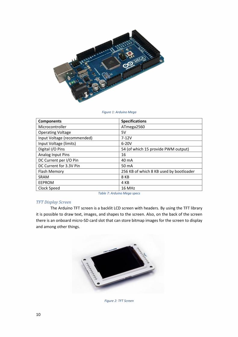
Arduino Mega 2560
The Arduino Mega 2560 is a microcontroller board based on the ATmega2560. It has
54 digital input/output pins (of which 15 can be used as PWM outputs), 16 analog inputs, 4
UARTs (hardware serial ports), a 16 MHz crystal oscillator, a USB connection, a power jack, an
ICSP header, and a reset button.
10
Figure 1: Arduino Mega
Components Specifications
Microcontroller ATmega2560
Operating Voltage 5V
Input Voltage (recommended) 7-12V
Input Voltage (limits) 6-20V
Digital I/O Pins 54 (of which 15 provide PWM output)
Analog Input Pins 16
DC Current per I/O Pin 40 mA
DC Current for 3.3V Pin 50 mA
Flash Memory 256 KB of which 8 KB used by bootloader
SRAM 8 KB
EEPROM 4 KB
Clock Speed 16 MHz Table 7: Arduino Mega specs
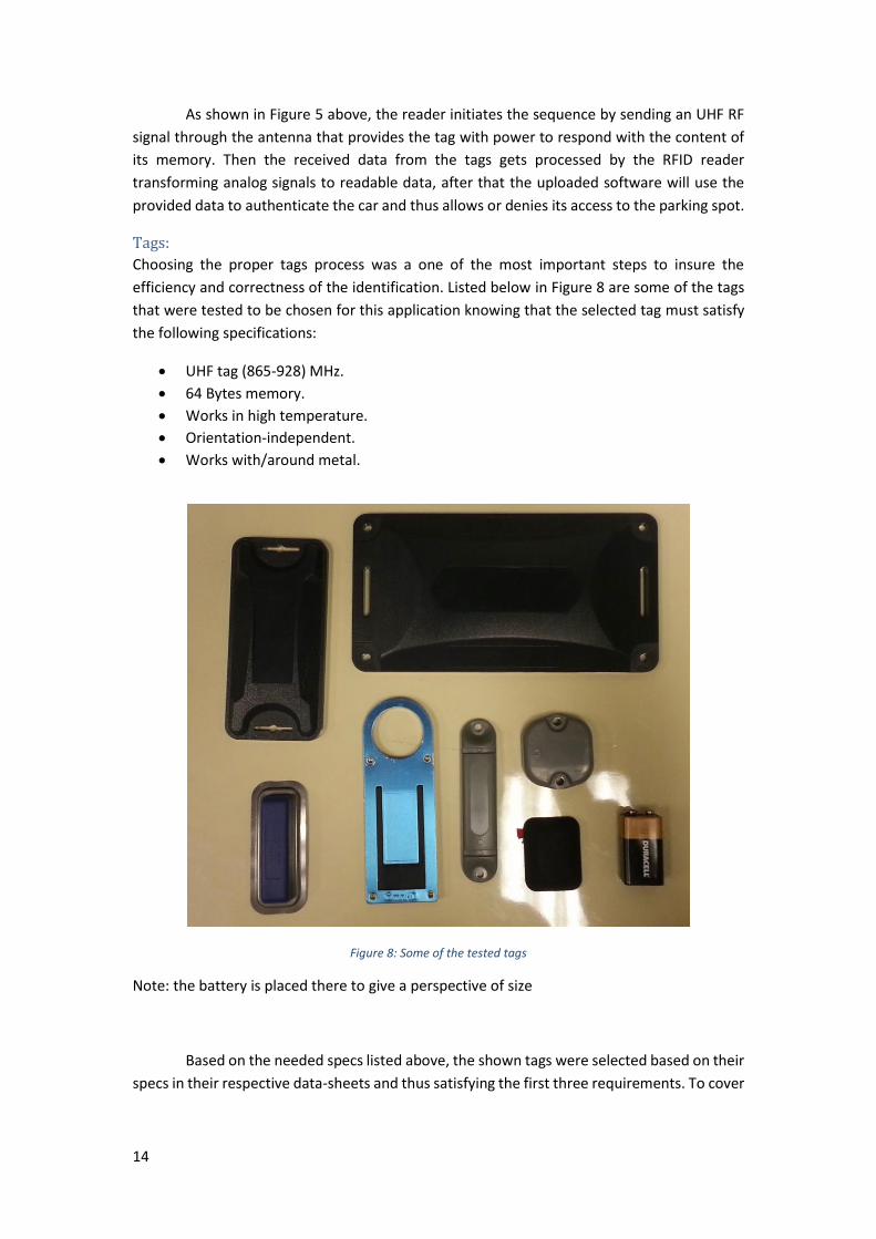
TFT Display Screen
The Arduino TFT screen is a backlit LCD screen with headers. By using the TFT library
it is possible to draw text, images, and shapes to the screen. Also, on the back of the screen
there is an onboard micro-SD card slot that can store bitmap images for the screen to display
and among other things.
Figure 2: TFT Screen

11
TFT Library
This library allows an Arduino board to communicate with the Arduino TFT LCD screen.
It simplifies the process for drawing shapes, lines, images, and text to the screen.
Grove - Relay
The Grove - Relay is a digital, normally-open switch that controls a relay capable of
switching much higher voltages and currents than the normal Arduino boards can support.
When set to HIGH, the LED will light up and the relay will close allowing current to flow. The
peak voltage capability is 250V at 10 amps.
Figure 3: Relay
Parking Space Guard
The parking space guard is a mechanical device that used in parking spaces to prevent
unauthorized individual from parking using a digital signal (remote control, RFID reader,
microcontroller, etc.). By using an arm that rise to achieve the purpose of the parking space
guard. It is powered using high voltage (battery, solar, direct AC connection). For the purpose
of this project we didn’t use any of the blocking devices instead we used a radio car antenna
as a symbol of blocking device.
Custom hardware and software components
Hardware components (the blocking device)
Instead of using a big and costly blocking device that exist in the market, we used a
simple car antenna to represent the blocking and a relay to control it using a digital signal.
Software components
RSA encryption/decryption library.
Due to the need to a functioning and safe security method to ensure the eligibility and
validity of the tags, a secure method of encryption and decryption was needed, that’s why a
stand-alone RSA encryption tool was developed using java security library and an open-source
library with optimization and customization to meet the needs of this project. Full code of the
library is provided in the Appendix.
Arduino code
Our system has very specific task and finding a software code that satisfy the
requirements of this system is almost impossible. Because of that we had to write our own
code to fulfil the requirements.

12
Design and implementation
Identification system
In order to understand the next part, you must have a basic understanding of the RFID
technology, the next part explains briefly the RFID technology. If you are comfortable with this
technology you can skip the coming part.
RFID (Radio Frequency Identification) is a wireless technology that utilizes the radio
frequency for data transmission. The data is stored on tags, these tags can be either passive,
active or battery-assisted-passive (BAP). The active and BAP tags both contain batteries that
allows them to communicate in a wider range that can go up to 1 km for enterprise uses and
over 2 km in military applications. Unlike battery powered tags, passive tags uses the RF signal
provided by the reader to generate power and transmit/receive data. Shown in Figure 4 a
schematic of a passive RFID tag that is powered by the reader’s RF signal using a coil. This
property of passive tags allows it to be very cheap and gives it a long life time, but it also
introduces a bigger issue which is the orientation dependence. Based on the architecture of
the passive tags, the positioning of the coil/s that power the tag is crucial and can cause it
work in limited range of angles.
Figure 4: Architicture of RFID system
This part of the system is composed of three hardware parts and two other software
parts. Table 8 and Figure 5, 6 and 7 show the components of this subsystem and a flowchart
that describes how it works.

13
Figure 5: System architecture
Figure 6: UHF RFID antenna
Figure 7: UHF RFID reader
Component Function
Antenna Transceiving the RF signal
RFID reader Signals modulation. Code execution (JVM) Control signals (digital I/O)
Encryption Tool Validation of the tag Table 8: Identification system components
14
As shown in Figure 5 above, the reader initiates the sequence by sending an UHF RF
signal through the antenna that provides the tag with power to respond with the content of
its memory. Then the received data from the tags gets processed by the RFID reader
transforming analog signals to readable data, after that the uploaded software will use the
provided data to authenticate the car and thus allows or denies its access to the parking spot.
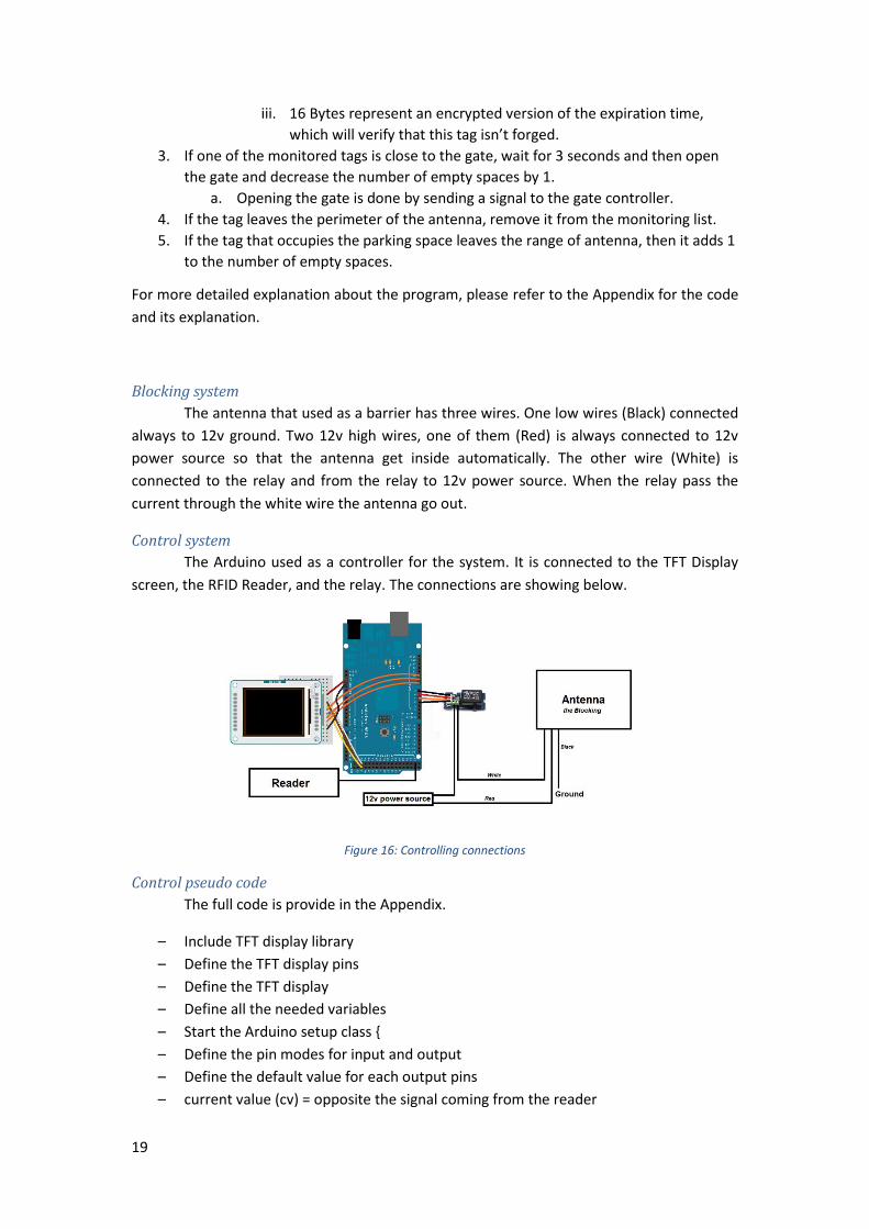
Tags:
Choosing the proper tags process was a one of the most important steps to insure the
efficiency and correctness of the identification. Listed below in Figure 8 are some of the tags
that were tested to be chosen for this application knowing that the selected tag must satisfy
the following specifications:
UHF tag (865-928) MHz.
64 Bytes memory.
Works in high temperature.
Orientation-independent.
Works with/around metal.
Figure 8: Some of the tested tags
Note: the battery is placed there to give a perspective of size
Based on the needed specs listed above, the shown tags were selected based on their
specs in their respective data-sheets and thus satisfying the first three requirements. To cover

15
the other required specifications multiple test were conducted on the tags shown below to
choose the appropriate tag for this application.
The first test was the Orientation-Dependence test, this test was conducted to verify
how every tag reacts to different angles and orientations with respect to the antenna. That’s
why three RFID readers were used to measure the power received from the tag (RSSI) in
various orientations. Shown in the figures 9, 10 and 11 below some of the results acquired for
RSSI using a handheld RFID reader, and the following graphs show the RSSI received by the
tags using the stationary RFID reader. These graphs were generated by recording 300 RSSI
values of a tag while moving it in different directions and orientations, then these values
where averaged (every 10 values averaged to a single value) and thus reducing the domain to
30 values instead of 300 to overcome the normal RSSI misreads.
Figure 9: A medium level RSSI tag
Figure 10: Low level RSSI tag
Figure 11: A high level RSSI tag

16
Figure 12: Values of RSSI on Different Orientations
Figure 13: Values of RSSI on Different Orientations (The selected Tag)
Since the system will be placed inside a car parking lot, then it’s expected to have a
metal-rich environment and thus it can cause inaccurate readings or even destroy the signals
causing it to be blocked completely. That’s why this issue must be considered in the early
stages of the implementation. This test was conducted to validate the accuracy and validity of
the readings in an environment with a lot of metallic objects. The test is very similar to the
previous one except it only consider the metallic environment and concentrates on receiving
the best readings around metallic objects.
As a result of the previous tests, two types of tags that are shown in the figures 14
and 15 below have shown to be to be most appropriate and suitable for this application, the
tag on the right (Tag B) was selected due to its smaller size and cheaper price. A comparison
between the two tags by the manufacturer and a full specifications of the selected tag are
provided in the Appendix.
-600
-550
-500
-450
-400
-350
-300
0 5 10 15 20 25 30 35
Values of RSSI on Different Orientations
-600
-550
-500
-450
-400
-350
-300
0 5 10 15 20 25 30 35
Values of RSSI on Different Orientations

17
Figure 14: Tag A
Figure 15: Tag B
Tag Storage
The used tag has a 64 Byte of storage. This space is used to authenticate the tag by
the reader. Table 9 below shows how this 64 Bytes are divided and used. The use of the second
and third fields (Owner ID, Owner Mobile Number) are used for checking the tag manually.
For example, it can be used by the security guards. The use of the other fields will be explained
in the next section.
1 2 3 4 5 6 7 8
1 Tag Signature (0x0000FFFF) Tag is Local or Public (0000FFFF OR FFFF0000)
2 Owner ID Owner mobile number
3
4
5 Long Value (Issue Time)
6 Expiration Time (Signed)
7
8 Long Value for (Expiration Time) Table 9: Tag storage block
RFID Reader
The RFID reader is the main component of this project. It’s the one responsible for
identifying and authenticating cars (Tags). That’s why choosing the right reader is an
important part of the design and implementation. In our case there were only two available
options to be used that were provided by the RFID Lab at KFUPM which are Motorola and
SIRIT readers. These two readers could work perfectly with this application, but each one of
them would have a slightly different implementation than the other and that’s due the extra
features in the SIRIT reader.
The SIRIT reader which is the one chosen for this project has a feature that
extinguished it from the other readers which is the JVM. SIRIT reader has a built in Java Virtual
Machine that can run java applications using the RAPID (RFID Application Programming
Interface for Developers) library, which is the standard libraries for developing RFID

18
applications. This extra feature allows us to use the SIRIT reader as a stand-alone system since
it’s the one doing the processing and due to using the RAPID library, we can re-use the code
on another reader that supports RAPID.
In addition to the local JVM, SIRIT reader has an extra feature that makes it a perfect
choice for our solution which is the digital I/O ports. The SIRIT reader is equipped with a
general purpose DIO ports that provides four optically isolated 5-24 Vdc input signals and four
open-collector output signals. The inputs can be used as general purpose inputs or to trigger
the reader for tag reading. These inputs can be configured for external read trigger from
proximity sensors, switches, or other devices. The outputs can be used as general purpose
outputs, to indicate tag reading activity, or to indicate the reader is transmitting (RF On). The
outputs can also be configured to trigger any other digitally controlled device. The table 9
below shows the specifications of the digital I/O ports as provided by the manufacturer.
Connector Phoenix Contact PN 1881422
Input 5 to 24 Vdc, 1 to 5 mA, Optically Isolated
Output Open Collector (3 to 40 V, 100 mA Max)
Signals Pin 1 Digital Common Voltage Reference for DIN1/DIN2
Pin 2 DIN1 (Digital Input 1)
Pin 3 DIN2 (Digital Input 2)
Pin 4 Digital Common Voltage Reference for DIN2/DIN4
Pin 5 DIN3 (Digital Input 3)
Pin 6 DIN4 (Digital Input 4)
Pin 7 Digital Common Ground
Pin 8 DOUT1 (Digital Output 1)
Pin 9 DOUT2 (Digital Output 2)
Pin 10 DOUT3 (Digital Output 3)
Pin 11 DOUT4 (Digital Output 4)
Pin 12 Digital Common Ground
Note Pins 7 and 12 can be used for both inputs and outputs.
Pin 1 is on the left when facing the end of the reader
Table 10: Digital pins description
Developing Software for the Reader
As mentioned earlier, the RAPID libraries were used to develop the Java program for the
reader. Shown below the algorithm used to detect/authenticate and process the detected
tags.
1. Detect newly arriving tags.
2. Check if the tags are valid (official and non-expired tag) and add them to a list to be
monitored.
a. The validation occurs on three stages
i. Validate the tag signature, which indicates that this tag is one of the
issued tags for the handicapped.
ii. Validate the expiration time, which are represented in the last 8
bytes in the memory as a Long number (milliseconds since
1/1/1970).
19
iii. 16 Bytes represent an encrypted version of the expiration time,
which will verify that this tag isn’t forged.
3. If one of the monitored tags is close to the gate, wait for 3 seconds and then open
the gate and decrease the number of empty spaces by 1.
a. Opening the gate is done by sending a signal to the gate controller.
4. If the tag leaves the perimeter of the antenna, remove it from the monitoring list.
5. If the tag that occupies the parking space leaves the range of antenna, then it adds 1
to the number of empty spaces.
For more detailed explanation about the program, please refer to the Appendix for the code
and its explanation.
Blocking system
The antenna that used as a barrier has three wires. One low wires (Black) connected
always to 12v ground. Two 12v high wires, one of them (Red) is always connected to 12v
power source so that the antenna get inside automatically. The other wire (White) is
connected to the relay and from the relay to 12v power source. When the relay pass the
current through the white wire the antenna go out.
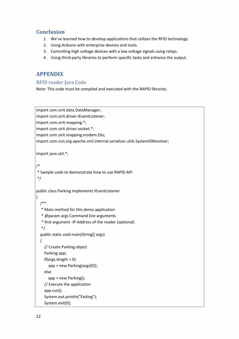
Control system
The Arduino used as a controller for the system. It is connected to the TFT Display
screen, the RFID Reader, and the relay. The connections are showing below.
Figure 16: Controlling connections
Control pseudo code
The full code is provide in the Appendix.
– Include TFT display library
– Define the TFT display pins
– Define the TFT display
– Define all the needed variables
– Start the Arduino setup class {
– Define the pin modes for input and output
– Define the default value for each output pins
– current value (cv) = opposite the signal coming from the reader

20
– Write the initial value on the screen
– } Exit the setup class
– Start the Arduino loop class {
– Write the new value on the screen
– New value (nv) = signal coming from the reader
– If cv != nv (
– Check the coming signal twice with a 5s delay in between
– Close or open the gate based on the signal
– Refresh the counter
– Write the new value on the screen
– Cv = nv
– ) exit if statement
– } exit the loop class
System integration The first step was testing every sub-system individually and prove its functionality.
After that, the identification sub-system was connected to the blocking and counting sub-
systems. At this point the first issue appeared which was in the signal sent from the reader to
the controller (more on this issue is in the next section). After fixing the past issue and insuring
a correct signal transmission between the reader and the controller, another problem
appeared in the code of the controller which was due a mistake in the code of the controller
when the received signal goes from HIGH to LOW multiple times. After testing and debugging
for multiple times and ensuring functionality, some extra tests were conducted on the tags
with different antenna to test the extendibility of the system.
Issues
Problems and challenges All the project problems are listed in the following tables, including the unsuccessful
attempts and final solution:
The issue Unsuccessful Attempts
Cause of failure Final resolution
Running the code on the reader.
Adding the RAPID library in the same directory
Not specifying the classpath on execution
Define the class path of the RAPID library on executing the program.
Digital I/O not working
Changing the connections of the ground cable.
Unclear understanding of the open-collector output.
Providing the voltage on the digital output, which causes it to work as a switch.
Buying the blocking device
Buying online Too expensive and too heavy to ship
Building our own blocking device
Buying from a local sellers
few number of seller and high price

21
Building the blocking device
Building from the scratch
To complex, need a lot of equipment and components
Buying a representative device
Choosing the representative device
An led light Doesn’t represent the blocking in a right way
Buying a car antenna and use it as a blocking device with a relay to control it
Refreshing the text on the tft screen
Filling the screen and un fill it
text appear on top pf each other
Over write the same text on above the old text with the same color as the background and then write the new text with a different color using the stroke method
Resetting the screen
Same problem as before
Table 11: List of issues
Limitations and constraints of the design. The project is a standalone system with no interface to communicate with other
systems. So, any additional communication with this system need an extra effort to make it
work. For example, if the system need to store the data in a log file it will need an extra
storage, extra interface, and extra programming.
The design depends heavily on the RSSI where it differs from one manufacturer to
another. This might introduce an issues related to the distances estimations.
Limitations and constraints of the implementation. The TFT screen library designed for only this type of screens. So if we need to change
the screen for any other display, the Arduino code must be modified to take care of the new
display. For example, if the TFT screen changed to a monitor and connected through VGA or
HDMI its need an extra Arduino shield and modify the code. Even if it is changed to a seven
segment display the connection and the code will be changed.
There are some limitations caused by the specifications of the RFID reader. For
example, the maximum length of the coaxial cable between the antenna and the reader is 15
meters. Also, this constrain apply to the length of the Ethernet cable.
One extra limitation in the implementation is the number of digital I/O ports in the
RFID reader, where it only supports 4 digital output ports, and thus it covers only 4 parking
spaces.
Engineering Tools and Standards 1. IntelliJ idea (JAVA IDE)
2. Arduino IDE
3. Sketch Up Pro
4. RAPID Library
5. RSA Encryption library
6. TFT Library
22
Conclusion 1. We’ve learned how to develop applications that utilizes the RFID technology.
2. Using Arduino with enterprise devices and tools.
3. Controlling high voltage devices with a low voltage signals using relays.
4. Using third-party libraries to perform specific tasks and enhance the output.
APPENDIX
RFID reader Java Code Note: This code must be compiled and executed with the RAPID libraries.
import com.sirit.data.DataManager;
import com.sirit.driver.IEventListener;
import com.sirit.mapping.*;
import com.sirit.driver.socket.*;
import com.sirit.mapping.modem.Dio;
import com.sun.org.apache.xml.internal.serializer.utils.SystemIDResolver;
import java.util.*;
/*
* Sample code to demonstrate how to use RAPID API
*/
public class Parking implements IEventListener
{
/**
* Main method for this demo application
* @param args Command line arguments
* first argument -IP Address of the reader (optional)
*/
public static void main(String[] args)
{
// Create Parking object
Parking app;
if(args.length > 0)
app = new Parking(args[0]);
else
app = new Parking();
// Execute the application
app.run();
System.out.println("Exiting");
System.exit(0);

23
}
/*
* IP Address of the reader, default is local host
*/
private static final String officialTagSignature = "0000FFFF";
private String ipAddress = "127.0.0.1";
DataManager dataManager = null;
DioManager dioManager = null;
boolean isFreeSpace = true;
String parkedCarTagId = "";
ArrayList<String> monitor = new ArrayList<String>();
/**
* Constructor
*/
public Parking()
{
}
/**
* Constructor - with IP Address
* @param ipAddr IP Address for the reader
*/
public Parking(String ipAddr)
{
ipAddress = ipAddr;
}
/**
* Executes the application
*/
public void run()
{
try
{
long startTime = System.currentTimeMillis();
// Open a connection to the reader
dataManager = new DataManager(DataManager.ConnectionTypes.SOCKET, ipAddress,
0);
dataManager.open();
System.out.println("Connection Opened");
// Get the reader's name
24
InfoManager infoManager = new InfoManager(dataManager);
String v = infoManager.getName();
System.out.println("Name: " + v);
infoManager = null;
// Login as administrator
ReaderManager readerManager = new ReaderManager(dataManager);
if(!readerManager.login("admin", "readeradmin"))
throw new Exception("Login attempt failed: " +
readerManager.getLastErrorMessage());
v = readerManager.whoAmI();
System.out.println("Login: " + v);
// Open an event channel and get it's ID
String id = dataManager.getEventChannel(this);
System.out.println("Event Channel ID: " + id);
//Initialize a TagManager Object
TagManager tagManager = new TagManager(dataManager);
tagManager.setReportingArriveFields("tag_id user_data rssi");
tagManager.setReportingDepartFields("tag_id time");
tagManager.setReportingReportFields("tag_id rssi");
//Initialize a Digital I/O manager
dioManager = new DioManager(dataManager);
// Register for event.tag.arrive
if(!readerManager.eventsRegister(id, "event.tag.arrive"))
throw new Exception("Failure to register for event: " +
readerManager.getLastErrorMessage());
System.out.println("Registered for event.tag.arrive");
// Register for event.tag.depart
if(!readerManager.eventsRegister(id, "event.tag.depart"))
throw new Exception("Failure to register for event: " +
readerManager.getLastErrorMessage());
System.out.println("Registered for event.tag.depart");
// Register for event.tag.report
if(!readerManager.eventsRegister(id, "event.tag.report"))
throw new Exception("Failure to register for event: " +
readerManager.getLastErrorMessage());
System.out.println("Registered for event.tag.report");

25
// Set operating mode to active
SetupManager setupManager = new SetupManager(dataManager);
setupManager.setOperatingMode(SetupManager.OPERATING_MODE_TYPES.ACTIVE);
System.out.println("Operating Mode: Active");
// Sleep while handling tag events
Thread.sleep(36000000);
// Unregister for event.tag.report
if(!readerManager.eventsUnregister(id, "event.tag.arrive"))
throw new Exception("Failure to unregister for event: " +
readerManager.getLastErrorMessage());
System.out.println("Unregistered for event.tag.arrive");
// Unregister for event.tag.depart
if(!readerManager.eventsUnregister(id, "event.tag.depart"))
throw new Exception("Failure to unregister for event: " +
readerManager.getLastErrorMessage());
System.out.println("Unregistered for event.tag.depart");
// Unregister for event.tag.report
if(!readerManager.eventsUnregister(id, "event.tag.report"))
throw new Exception("Failure to unregister for event: " +
readerManager.getLastErrorMessage());
System.out.println("Unregistered for event.tag.report");
// Set operating mode to standby
setupManager.setOperatingMode(SetupManager.OPERATING_MODE_TYPES.STANDBY);
System.out.println("Operating Mode: Standby");
// Close the connection
setupManager = null;
readerManager = null;
dataManager.close();
System.out.println("Connection Closed");
// Output the time to execute application
long endTime = System.currentTimeMillis();
long t = endTime - startTime - 500;
System.out.println("Estimated Time: " + t + "(ms)");
}
catch(Exception e)

26
{
System.out.println("Error: " + e.getMessage());
}
}
/**
* Common Event Handler for all of the triggered (registered) events
*/
public void EventFound(Object sender, EventInfo eventInfo)
{
String eventName = eventInfo.getName();
if(eventName.equalsIgnoreCase("event_tag_arrive"))
tagArrivedEventHandler(sender, eventInfo);
else if(eventName.equalsIgnoreCase("event_tag_depart"))
tagDepartEventHandler(sender, eventInfo);
else if(eventName.equalsIgnoreCase("event_tag_report"))
tagReportEventHandler(sender, eventInfo);
}
//Validates the tag based on its ID.
//Every user can implement their own criteria.
public boolean isOfficialTagID(String tagId)
{
return true;
}
//Validating the tag based on the content.
//In this case, the signature for any official tag is (0000FFFF)HEX
public boolean isOfficialTagData(String tagUserData)
{
if(tagUserData != null)
if(tagUserData.substring(2,10).equalsIgnoreCase(officialTagSignature))
return true;
return false;
}
//Event handler for newly arrived tag in the field of the antenna.
public void tagArrivedEventHandler(Object sender, EventInfo eventInfo)
{
if(isFreeSpace)
{
String tagID =
eventInfo.getParameter(EventInfo.EVENT_TAG_ARRIVE_PARAMS.TAG_ID);
String data =
eventInfo.getParameter(EventInfo.EVENT_TAG_ARRIVE_PARAMS.USER_DATA);
String rssi = eventInfo.getParameter(EventInfo.EVENT_TAG_ARRIVE_PARAMS.RSSI);

27
long arriveTime = System.currentTimeMillis();
//Checking the validity of the tag based on the ID
if(tagID!= null) //This is done to avoid the issue of miss-read tag ID.
if(isOfficialTagID(tagID))
{
//Checking the validity of the tag based on the data
if(data != null) //This is done to avoid the issue of miss-read tag user-data.
if(isOfficialTagData(data))
{
if(isAllowedToPark(data))
{
System.out.println(tagID + " is Allowed to park !!");
addToMonitorList(tagID);
}
}
}
}
}
//This is a continuous scan for all the tags in the range of the antenna/s.
public void tagReportEventHandler(Object sender, EventInfo eventInfo)
{
String tagID =
eventInfo.getParameter(EventInfo.EVENT_TAG_ARRIVE_PARAMS.TAG_ID);
String data =
eventInfo.getParameter(EventInfo.EVENT_TAG_ARRIVE_PARAMS.USER_DATA);
String rssi = eventInfo.getParameter(EventInfo.EVENT_TAG_ARRIVE_PARAMS.RSSI);
if(isFreeSpace & monitor.contains(tagID))
{
int RSSI = Integer.parseInt(rssi);
if(RSSI < -400 && RSSI > -500 ) //Range of RSSI for a close tag.
{
openGate();
parkedCarTagId = tagID;
isFreeSpace = false;
}
}
28
}
//This event is triggered if a tag isn't detected within n milliseconds.
//The number of seconds can be configured. In this case, it's 3000 milliseconds
public void tagDepartEventHandler(Object sender, EventInfo eventInfo)
{
String tagID =
eventInfo.getParameter(EventInfo.EVENT_TAG_ARRIVE_PARAMS.TAG_ID);
String data =
eventInfo.getParameter(EventInfo.EVENT_TAG_ARRIVE_PARAMS.USER_DATA);
String rssi = eventInfo.getParameter(EventInfo.EVENT_TAG_ARRIVE_PARAMS.RSSI);
if(tagID.equalsIgnoreCase(parkedCarTagId))
{
parkedCarTagId = "";
isFreeSpace = true;
closeGate();
}
if(monitor.contains(tagID))
monitor.remove(tagID);
}
private void openGate()
{
//Open the gate
try
{
dioManager.setOut4("1");
System.out.println("Gate Opened");
}
catch (Exception e)
{
System.out.println("Error: " + e.getMessage());
}
}
private void closeGate()
{
//Close the gate
try
{
dioManager.setOut4("0");
System.out.println("Gate Closed");

29
}
catch (Exception e)
{
System.out.println("Error: " + e.getMessage());
}
}
//Adding a tag-id to the monitor list keeps allows the program to keep checking it to
see if it's in the right position.
private void addToMonitorList(String tagId)
{
System.out.println(tagId + " added to monitor");
monitor.add(tagId);
}
//Checks if the tag owner is allowed to use this space based on the expiration time in
the tag.
private boolean isAllowedToPark(String data)
{
String timeFromTag = data.substring(114);
long time = Long.parseLong(timeFromTag, 16);
if(time > System.currentTimeMillis())
return true;
return false;
}
}
RSA Code
import java.io.File;
import java.io.FileInputStream;
import java.io.FileNotFoundException;
import java.io.FileOutputStream;
import java.io.IOException;
import java.io.ObjectInputStream;
import java.io.ObjectOutputStream;
import java.security.KeyPair;
import java.security.KeyPairGenerator;
import java.security.NoSuchAlgorithmException;
import java.security.PrivateKey;
import java.security.PublicKey;
import javax.crypto.Cipher;

30
/**
* @author JavaDigest
*
*/
public class EncryptionUtil {
/**
* String to hold name of the encryption algorithm.
*/
public static final String ALGORITHM = "RSA";
/**
* String to hold the name of the private key file.
*/
public static final String PRIVATE_KEY_FILE = "C:/keys/private.key";
/**
* String to hold name of the public key file.
*/
public static final String PUBLIC_KEY_FILE = "C:/keys/public.key";
/**
* Generate key which contains a pair of private and public key using 1024
* bytes. Store the set of keys in Prvate.key and Public.key files.
*
* @throws NoSuchAlgorithmException
* @throws IOException
* @throws FileNotFoundException
*/
public static void generateKey() {
try {
final KeyPairGenerator keyGen = KeyPairGenerator.getInstance(ALGORITHM);
keyGen.initialize(512);
final KeyPair key = keyGen.generateKeyPair();
File privateKeyFile = new File(PRIVATE_KEY_FILE);
File publicKeyFile = new File(PUBLIC_KEY_FILE);
// Create files to store public and private key
if (privateKeyFile.getParentFile() != null) {
privateKeyFile.getParentFile().mkdirs();
}
privateKeyFile.createNewFile();

31
if (publicKeyFile.getParentFile() != null) {
publicKeyFile.getParentFile().mkdirs();
}
publicKeyFile.createNewFile();
// Saving the Public key in a file
ObjectOutputStream publicKeyOS = new ObjectOutputStream(
new FileOutputStream(publicKeyFile));
publicKeyOS.writeObject(key.getPublic());
publicKeyOS.close();
// Saving the Private key in a file
ObjectOutputStream privateKeyOS = new ObjectOutputStream(
new FileOutputStream(privateKeyFile));
privateKeyOS.writeObject(key.getPrivate());
privateKeyOS.close();
} catch (Exception e) {
e.printStackTrace();
}
}
/**
* The method checks if the pair of public and private key has been generated.
*
* @return flag indicating if the pair of keys were generated.
*/
public static boolean areKeysPresent() {
File privateKey = new File(PRIVATE_KEY_FILE);
File publicKey = new File(PUBLIC_KEY_FILE);
if (privateKey.exists() && publicKey.exists()) {
return true;
}
return false;
}
/**
* Encrypt the plain text using public key.
*
* @param text
* : original plain text
* @param key
* :The public key

32
* @return Encrypted text
* @throws java.lang.Exception
*/
public static byte[] encrypt(String text, PublicKey key) {
byte[] cipherText = null;
try {
// get an RSA cipher object and print the provider
final Cipher cipher = Cipher.getInstance(ALGORITHM);
// encrypt the plain text using the public key
cipher.init(Cipher.ENCRYPT_MODE, key);
cipherText = cipher.doFinal(text.getBytes());
} catch (Exception e) {
e.printStackTrace();
}
return cipherText;
}
public static byte[] encryptHex(String text, PublicKey key) {
byte[] cipherText = null;
try {
// get an RSA cipher object and print the provider
final Cipher cipher = Cipher.getInstance(ALGORITHM);
// encrypt the plain text using the public key
cipher.init(Cipher.ENCRYPT_MODE, key);
cipherText = cipher.doFinal(text.getBytes());
} catch (Exception e) {
e.printStackTrace();
}
return cipherText;
}
/**
* Decrypt text using private key.
*
* @param text
* :encrypted text
* @param key
* :The private key
* @return plain text
* @throws java.lang.Exception
*/
public static String decrypt(byte[] text, PrivateKey key) {
byte[] dectyptedText = null;
try {

33
// get an RSA cipher object and print the provider
final Cipher cipher = Cipher.getInstance(ALGORITHM);
// decrypt the text using the private key
cipher.init(Cipher.DECRYPT_MODE, key);
dectyptedText = cipher.doFinal(text);
} catch (Exception ex) {
ex.printStackTrace();
}
return new String(dectyptedText);
}
/**
* Test the EncryptionUtil
*/
public static void main(String[] args) {
try {
// Check if the pair of keys are present else generate those.
if (!areKeysPresent()) {
// Method generates a pair of keys using the RSA algorithm and stores it
// in their respective files
generateKey();
}
final String originalText = "Text to be encrypted ";
ObjectInputStream inputStream = null;
// Encrypt the string using the public key
inputStream = new ObjectInputStream(new FileInputStream(PUBLIC_KEY_FILE));
final PublicKey publicKey = (PublicKey) inputStream.readObject();
final byte[] cipherText = encrypt(originalText, publicKey);
// Decrypt the cipher text using the private key.
inputStream = new ObjectInputStream(new FileInputStream(PRIVATE_KEY_FILE));
final PrivateKey privateKey = (PrivateKey) inputStream.readObject();
final String plainText = decrypt(cipherText, privateKey);
// Printing the Original, Encrypted and Decrypted Text
System.out.println("Original Text: " + originalText);
System.out.println("Encrypted Text: " +cipherText.toString());
System.out.println("Decrypted Text: " + plainText);

34
} catch (Exception e) {
e.printStackTrace();
}
}
}
Arduino Code
#include <SPI.h>
#include <TFT.h>
#define cs 10
#define dc 9
#define rst 8
TFT TFTscreen = TFT(cs, dc, rst);
int w = TFTscreen.width();
int h = TFTscreen.height();
int cv = 1;
int count = 1;
char sensorPrintout[4];
void setup() {
pinMode(2, OUTPUT);
pinMode(3, OUTPUT);
pinMode(4, OUTPUT);
pinMode(5, OUTPUT);
pinMode(6, OUTPUT);
pinMode(7, OUTPUT);
digitalWrite(2, LOW);
digitalWrite(3, HIGH);
digitalWrite(4, LOW);
digitalWrite(6, HIGH);
digitalWrite(7, LOW);
pinMode(22,INPUT);
pinMode(23,INPUT);
pinMode(24,INPUT);
pinMode(25,INPUT);
35
pinMode(26,INPUT);
digitalWrite(5, HIGH);
cv=digitalRead(22)^1;
TFTscreen.begin();
TFTscreen.background(0, 0, 0);
TFTscreen.stroke(255,255,255);
TFTscreen.setTextSize(1.5);
TFTscreen.text("Empty Parking # :\n ",0,0);
TFTscreen.setTextSize(5);
}
void loop() {
String countVal = String(count);
countVal.toCharArray(sensorPrintout, 4);
TFTscreen.stroke(255,255,255);
TFTscreen.text(sensorPrintout, w/2, h/2-5);
int nv = digitalRead(22);
if(cv!=nv){
if(digitalRead(22)==1){
delay(5000);
if(digitalRead(22)==1){
digitalWrite(5,LOW);
count = 0;
}
}
if(digitalRead(22)==0){
delay(5000);
if(digitalRead(22)==0){
digitalWrite(5,HIGH);
count = 1;
}
}
cv=nv;
TFTscreen.stroke(0,0,0);
TFTscreen.text(sensorPrintout, w/2, h/2-5);
}
}

Visit www.omni-id.com to learn more about
the complete line of Omni-ID RFID products.
Building Intelligent Supply ChainsWith an excellent read range across all geographic regions and a durable, high heat resistant encasement, the Dura 1500 is best suited to outdoor applications, including:
�Container tracking for yard management.
�Cargo tracking.
�Defense asset management.
DS0021-C PAGE 1 OF 2
Omni-ID® Dura 1500 Omni-ID Dura 1500 is the most durable and long range tag
product offering long read ranges across all geographies.
Designed with heavy industry in mind, the Omni-ID Dura 1500
features extreme impact resistance and high temperature
ratings, enabling it to be deployed in outdoor heavy industry
environments anywhere in the world.
mm14 mm
Dimensions stated in mm
Radiation PatternsLarge Metal
Sheet
Physical Specifications
Encasement ABS or Polycarbonate
Size (mm)(tolerance)
140 x 66 x 14.0( +/–1.0 )
Size (in)(tolerance)
5.51 x 2.6 x 0.55( +/–0.04 )
Weight (g) 79.0 (ABS) 82.0 (PC)
RF Specifications
Protocol EPC Class 1 Gen2
Frequency Range (MHz) 860–960 (global)
Read Range (Fixed reader)1 Up to 15.0 (global)
Read Range (Handheld reader)1 Up to 7.5 (global)
Material Compatibility Optimized for metal
IC Type (chip) Alien H3
Memory 2 EPC - 96bitsUser - 512bitsTID - 64bits
1. Quoted performance achieved using standard testing methodology. Read range will vary with reader hardware and output power.
2. EPC and User memory are reprogrammable, TID is locked at point of manufacture.
Visit www.omni-id.com to learn more about
the complete line of Omni-ID RFID products.
©2013 Omni-ID Cayman, Ltd. All rights reserved.
DS0021-C PAGE 2 OF 2 042013
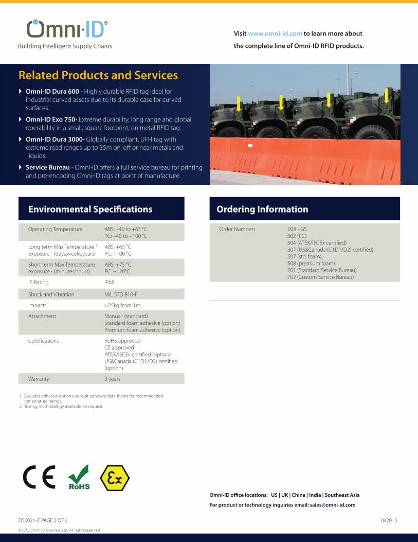
Related Products and Services�Omni-ID Dura 600 - Highly durable RFID tag ideal for
industrial curved assets due to its durable case for curved surfaces.
�Omni-ID Exo 750- Extreme durability, long range and global operability in a small, square footprint, on metal RFID tag.
�Omni-ID Dura 3000- Globally compliant, UFH tag with extreme read ranges up to 35m on, off or near metals and liquids.
�Service Bureau - Omni-ID offers a full service bureau for printing and pre-encoding Omni-ID tags at point of manufacture.
Ordering Information
Order Numbers 008 - GS:302 (PC):304 (ATEX/IECEx certified):307 (US&Canada (C1D1/D2) certified):507 (std. foam),:508 (premium foam) :701 (Standard Service Bureau):702 (Custom Service Bureau)
Environmental Specifications
Operating Temperature ABS: –40 to +65 °CPC: –40 to +100 °C
Long term Max Temperature 1
exposure - (days,weeks,years) ABS: +65 °CPC: +100 °C
Short term Max Temperature 1
exposure - (minutes,hours) ABS: +75 °CPC: +120°C
IP Rating IP68
Shock and Vibration MIL STD 810-F
Impact2 >25kg from 1m
Attachment Manual (standard)Standard foam adhesive (option)Premium foam adhesive (option)
Certifications RoHS approvedCE approvedATEX/IECEx certified (option)US&Canada (C1D1/D2) certified (option)
Warranty 3 years
Omni-ID office locations: US | UK | China | India | Southeast Asia
For product or technology inquiries email: [email protected]
1. Excludes adhesive options, consult adhesive data sheets for recommended temperature ratings.
2. Testing methodology available on request

DS0002-23H
Visit the Omni-ID Store at www.omni-id.com to learn more about the complete line of Omni-ID RFID products.
Dura Range - Heavy Duty
Product Name Dura 600 Dura 1500 Dura 3000
Typical Applications
Maintenance for deployed field equipment.
Chemical drum tracking.
Beverage keg tracking.
Container tracking for yard management.
Cargo tracking.
Defense asset management.
Cargo and container tracking.
Heavy equipment tracking and maintenance.
Location identification in lay down zones.
RF S
peci
ficat
ions
Frequency Range (MHz)
902–928 (US)865–868 (EU)952–954 (JPN)
860–960 (global) 860–960 (global)
Read Range (m)- Fixed reader
Up to 6.0m (US)Up to 5.0m (EU)Up to 3.0m (JPN)
Up to 15.0 Up to 35.0
Material Compatibility Optimized for Metal substrates Optimized for Metal substrates Metal and non-metallic substrates
IC Type Alien Higgs 3 Alien Higgs 3 Alien Higgs 3
Phys
ical
and
Env
ironm
enta
l Sp
ecifi
catio
ns
Encasement Durable Thermoplastic Material ABS or Polycarbonate ABS or Polycarbonate
Size (mm) 48.5 x 38.0 x 9.5 140 x 66 x 14.0 210 x 110 x 21.0
Weight (g) 11.2 82.0 292
Operating Temperature Max Exposure Temp (°C)
-40 to +85 °C+105 °C
Polycarbonate : -40 to +100 °C
+120 °C
Polycarbonate : -40 to +100 °C
+120 °C
Ingress Protection IP68 IP68 IP68
Shock and Vibration MIL STD 810-F MIL STD 810-F MIL STD 810-F
Attachment Industrial Foam Tape Manual (standard)Standard foam adhesive (option)Premium foam adhesive (option)
Manual (standard)Standard foam adhesive (option)Premium foam adhesive (option)
Order Codes 025 - US, EU, JPN 008 - GS 009 - GS
+ Order Option Codes are listed on the datasheets.
Values for Comparison only, please refer to Product Datasheets for full specifications. ©2013 Omni-ID All rights reserved. DS0079-A 052013