Self Study Program 895803 - angelico.ca · iii Contents This Self-Study Program provides...
56
Service Training Self Study Program 895803 Volkswagen CC Overview
Transcript of Self Study Program 895803 - angelico.ca · iii Contents This Self-Study Program provides...

Service Training
Self Study Program 895803
Volkswagen CC Overview

Volkswagen of America, Inc.Volkswagen AcademyPrinted in U.S.A.Printed 10/2008
Course Number 859803
©2008 Volkswagen of America, Inc.
All rights reserved. All information contained in this manual is based on the latest information available at the time of printing and is subject to the copyright and other intellectual property rights of Volkswagen of America, Inc., its affi liated companies and its licensors. All rights are reserved to make changes at any time without notice. No part of this document may be reproduced, stored in a retrieval system, or transmitted in any form or by any means, electronic, mechanical, photocopying, recording or otherwise, nor may these materials be modifi ed or reposted to other sites without the prior expressed written permission of the publisher.
All requests for permission to copy and redistribute information should be referred to Volkswagen of America, Inc.
Always check Technical Bulletins and the latest electronic repair information for information that may supersede any information included in this booklet.
Trademarks: All brand names and product names used in this manual are trade names, service marks, trademarks, or registered trademarks; and are the property of their respective owners.

iii
Contents
This Self-Study Program provides information regarding the design and function of new models.This Self-Study Program is not a Repair Manual.
This information will not be updated.For maintenance and repair procedures, always refer to the latest electronic service information.
Note Important!
Introduction . . . . . . . . . . . . . . . . . . . . . . . . . . . . . . . . . . . . . . . . . . . . . . . . 1
Body . . . . . . . . . . . . . . . . . . . . . . . . . . . . . . . . . . . . . . . . . . . . . . . . . . . . . . 6
Occupant Protection . . . . . . . . . . . . . . . . . . . . . . . . . . . . . . . . . . . . . . . . 18
Engines . . . . . . . . . . . . . . . . . . . . . . . . . . . . . . . . . . . . . . . . . . . . . . . . . . . 20
Chassis . . . . . . . . . . . . . . . . . . . . . . . . . . . . . . . . . . . . . . . . . . . . . . . . . . . 22
Electronics . . . . . . . . . . . . . . . . . . . . . . . . . . . . . . . . . . . . . . . . . . . . . . . . 25
Radio and Telephone . . . . . . . . . . . . . . . . . . . . . . . . . . . . . . . . . . . . . . . . 33
Heating and Air Conditioning . . . . . . . . . . . . . . . . . . . . . . . . . . . . . . . . . 40
Electronic Systems . . . . . . . . . . . . . . . . . . . . . . . . . . . . . . . . . . . . . . . . . 44
Glossary . . . . . . . . . . . . . . . . . . . . . . . . . . . . . . . . . . . . . . . . . . . . . . . . . . 48
Knowledge Assessment . . . . . . . . . . . . . . . . . . . . . . . . . . . . . . . . . . . . . 51

Page intentionally left blank
1
Introduction
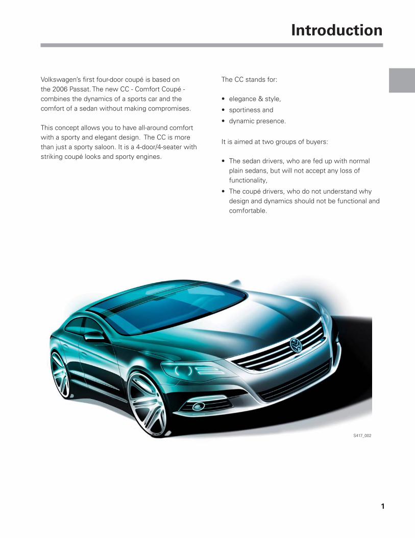
S417_002
Volkswagen’s fi rst four-door coupé is based on the 2006 Passat. The new CC - Comfort Coupé - combines the dynamics of a sports car and the comfort of a sedan without making compromises.
This concept allows you to have all-around comfort with a sporty and elegant design. The CC is more than just a sporty saloon. It is a 4-door/4-seater with striking coupé looks and sporty engines.
The CC stands for:
elegance & style,•
sportiness and•
dynamic presence.•
It is aimed at two groups of buyers:
The sedan drivers, who are fed up with normal • plain sedans, but will not accept any loss of functionality,
The coupé drivers, who do not understand why • design and dynamics should not be functional and comfortable.

2
Introduction
Volkswagen CC Features
Multi-function steering wheel•
Media Device Interface box • (MDI)

3
Introduction
Tilting panorama sunroof•
Optical park assistant•
Frameless doors and windows•
Pivoted badge with mounting • for reversing camera

4
Introduction
S417_066
981 2710
Technical Data
Exterior Dimensions and Weight
1105
4796
1422
1553
1856
S417_068
1557
S417_070
Length 4799 mm (188.9 inches)
Width 1855 mm (73 inches)
Height 1418 mm (55.8 inches)
Wheelbase 2711 mm (106.7 inches)
Track width at front 1553 mm (61.1 inches)
Track width at rear 1559 mm (61.4 inches)
Exterior dimensions
Curb weight without driver 1530 kg (3374 lb)
Tank capacity 70 liters (18.5 gallons)
Drag coeffi cient 0.297 cw
5
Introduction
375
949 930
514 522
S417_090
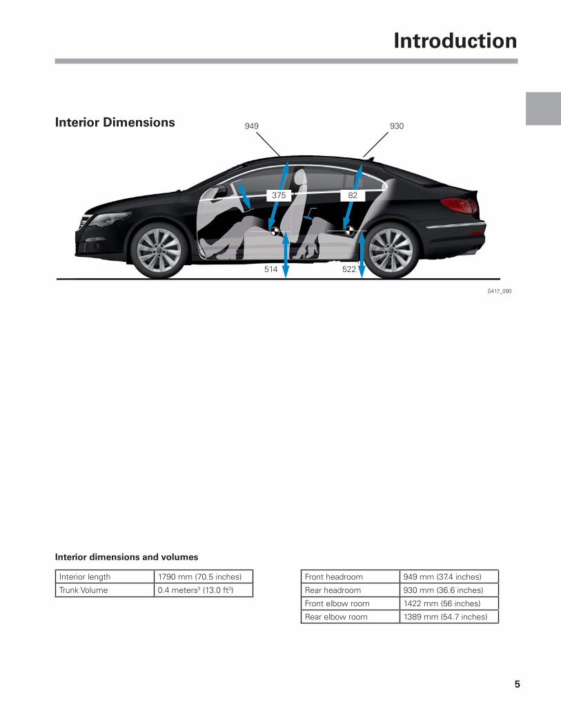
Interior Dimensions
Interior length 1790 mm (70.5 inches)
Trunk Volume 0.4 meters3 (13.0 ft3)
Front headroom 949 mm (37.4 inches)
Rear headroom 930 mm (36.6 inches)
Front elbow room 1422 mm (56 inches)
Rear elbow room 1389 mm (54.7 inches)
Interior dimensions and volumes
82
6
Body
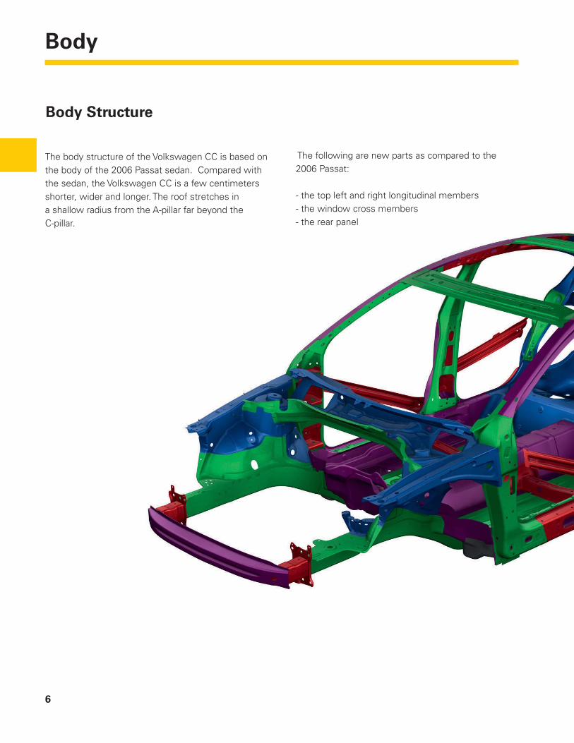
The following are new parts as compared to the 2006 Passat:
- the top left and right longitudinal members- the window cross members- the rear panel- the A-pillar reinforcement
Body Structure
The body structure of the Volkswagen CC is based on the body of the 2006 Passat sedan. Compared with the sedan, the Volkswagen CC is a few centimeters shorter, wider and longer. The roof stretches in a shallow radius from the A-pillar far beyond the C-pillar.

7
Body
S417_058
Sheet quality distribution
16%19%
27%
25%
13%
S417_108Legend
Steel Panels up to 140 MPa
High strength steel panels from 180 to 240 MPa
Higher - strength steel panels from 360 to 320 MPa
Ultra - high strength steel panels from 340 to 700 MPa
Ultra-high-strength, thermoformed steel panels over 1000 MPa
The types of steel sheet used in the Volkswagen CC are the same as the 2006 Passat. However, the Volkswagen CC uses more high to ultra-high strength thermoformed steel panels, allowing the body weight to be reduced without losing strength.
The pie chart shows the substantial proportion of higher strength and ultra-high-strength thermoformed steel panels as percentages.

8
Body
S417_062
S417_060
New Body Features
Tilting Panorama Sunroof
The optional tilting panorama sunroof consists of a large glass roof that is controlled by a roof control unit. The large glass roof is a single-piece glass lid driven by an electric motor. The roof controls are in a module mounted in the car headliner. Tinted glass and a fabric blind ensure a pleasant climate and good protection from the sun.
Module Construction
The tilting panorama sunroof is assembled as a top-load system. This means a roof module is fi tted or cemented to the body-in-white from above. This allows the glass areas to span a large section of the roof creating a fully glazed look.
This fully pre-assembled module with glass lid, blind system, guide rails, mechanism, mounting frame, electric motor drive and sealing system makes assembly easier and reduces the manufacturing costs. The mounting frame, which holds the whole system and guarantees vehicle stiffness, is made from fi berglass-reinforced plastic.
The front area of the roof between the front windscreen and the glass lid of the tilting panorama roof is integrated in the module and is gloss black. This color seems to extend the front window visually to behind the B-pillar and also contributes to the coupé-like looks of the Volkswagen CC.
Adhesive Bead Roof Module
The sealing system of the module guarantees water drainage to the outside. A separate water drainage system with drainage hoses is not required.

9
Body
S417_126
S417_150
Operation
The tilting panorama sunroof can be raised up to four centimeters (1.6 inches). The tilting panorama sunroof is operated using the two tilt position buttons that are operated by pulling or pushing the roof control. The buttons are connected directly to the tilting panorama sunroof control unit.
Tap Mode
When tapping the switch, the tilting panorama roof is automatically moved to either the tilt position or zero position. The automatic run can be cancelled by pressing or pulling the button during operation.
Hold Mode
The tilting panorama sunroof is opened or closed manually for the duration that the button is operated.
Sun Blind
The manual sunshade system on the tilting panorama sunroof is a complete and complex development compared to conventional sunshade systems:
An opaque blind fabric is used to increase the • level of shade.
The blind system is infi nitely variable regardless • of the opening position and has an additional front blind latch.
The blind system has steel tape guides at the • side to ensure that the fabric is tensioned.
The blind roller has been carefully adapted, i.e. • it is arched crossways to ensure the necessary headroom

10
Body
S417_102
Frameless Doors
The four doors are frameless. This allowed the roof to be lowered to create the coupé-like silhouette of the Volkswagen CC.
The door window fi ts into a 3-lip door-frame seal. The door window fi rst needs to be lowered out of the seal before the door can be opened. Therefore, whenever the door handle is actuated, the glass is lowered slightly.
This function in the Volkswagen CC window regulator system is extremely fast. This is partially achieved with a microswitch in the outside door handle. The lowering is started as soon as the door handle is pulled.
Cross-section through the roof frame seal
Roof Frame Seal
Door Window
S417_114
S417_114
S417_151
Microswitch
Door Handle Mounting
11
Body
Adjustment of the Door Windows
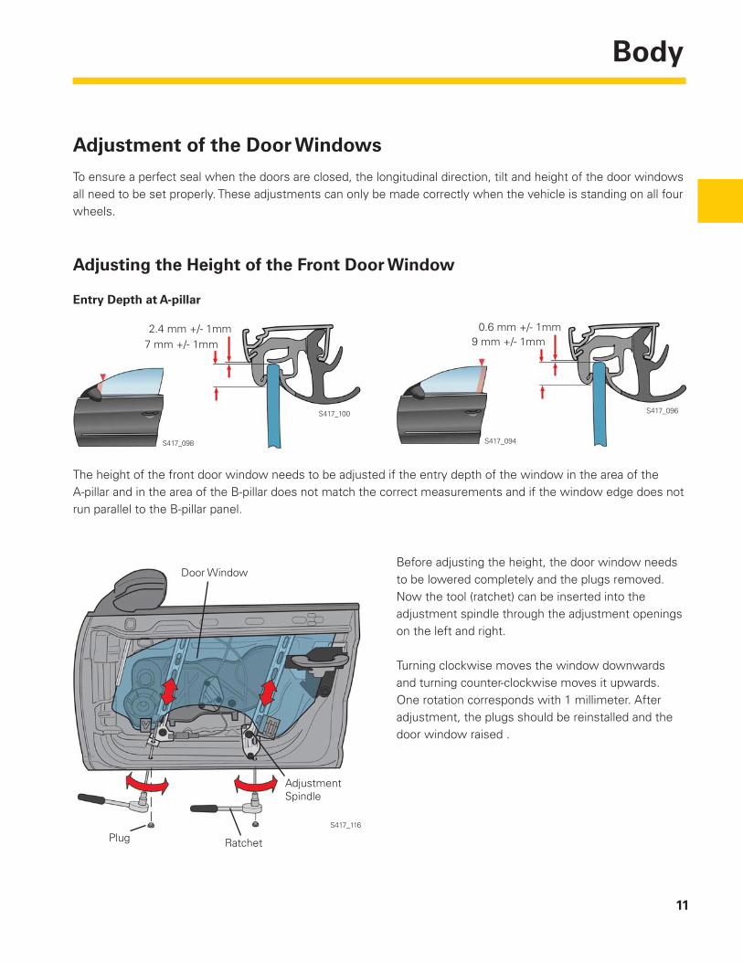
To ensure a perfect seal when the doors are closed, the longitudinal direction, tilt and height of the door windows all need to be set properly. These adjustments can only be made correctly when the vehicle is standing on all four wheels.
Adjusting the Height of the Front Door Window
S417_098
S417_100
S417_094
S417_096
2.4 mm +/- 1mm7 mm +/- 1mm
Entry Depth at A-pillar
The height of the front door window needs to be adjusted if the entry depth of the window in the area of the A-pillar and in the area of the B-pillar does not match the correct measurements and if the window edge does not run parallel to the B-pillar panel.
Door Window
Adjustment Spindle
Plug Ratchet
S417_116
Before adjusting the height, the door window needs to be lowered completely and the plugs removed. Now the tool (ratchet) can be inserted into the adjustment spindle through the adjustment openings on the left and right.
Turning clockwise moves the window downwards and turning counter-clockwise moves it upwards. One rotation corresponds with 1 millimeter. After adjustment, the plugs should be reinstalled and the door window raised .
0.6 mm +/- 1mm9 mm +/- 1mm
12
Body
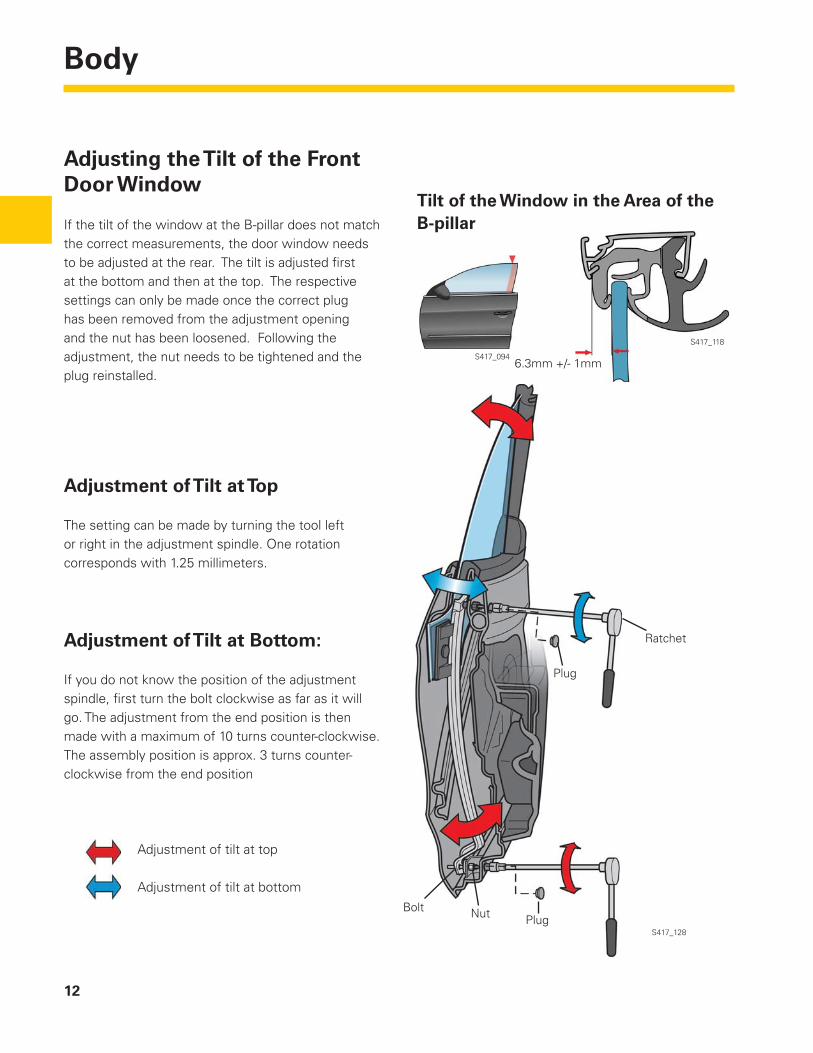
Adjusting the Tilt of the Front Door Window
If the tilt of the window at the B-pillar does not match the correct measurements, the door window needs to be adjusted at the rear. The tilt is adjusted fi rst at the bottom and then at the top. The respective settings can only be made once the correct plug has been removed from the adjustment opening and the nut has been loosened. Following the adjustment, the nut needs to be tightened and the plug reinstalled.
Tilt of the Window in the Area of the B-pillar
Adjustment of Tilt at Top
The setting can be made by turning the tool left or right in the adjustment spindle. One rotation corresponds with 1.25 millimeters.
Adjustment of Tilt at Bottom:
If you do not know the position of the adjustment spindle, fi rst turn the bolt clockwise as far as it will go. The adjustment from the end position is then made with a maximum of 10 turns counter-clockwise. The assembly position is approx. 3 turns counter-clockwise from the end position
Adjustment of tilt at top
Adjustment of tilt at bottom
S417_094
S417_118
6.3mm +/- 1mm
NutBoltPlug
Plug
Ratchet
S417_128
13
Body
Adjusting the Tilt of the Rear Door Window
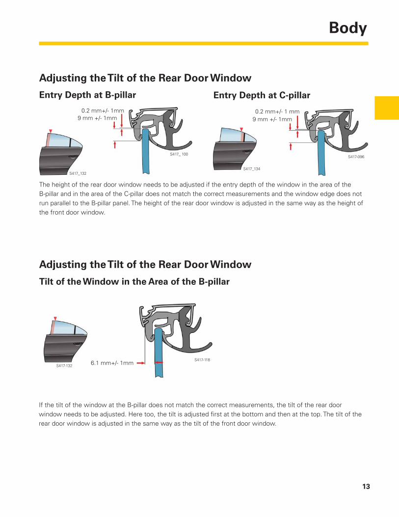
The height of the rear door window needs to be adjusted if the entry depth of the window in the area of the B-pillar and in the area of the C-pillar does not match the correct measurements and the window edge does not run parallel to the B-pillar panel. The height of the rear door window is adjusted in the same way as the height of the front door window.
S417_132
0.2 mm+/- 1mm9 mm +/- 1mm
0.2 mm+/- 1 mm9 mm +/- 1mm
S417_134
S417-096S417_ 100
Entry Depth at B-pillar Entry Depth at C-pillar
If the tilt of the window at the B-pillar does not match the correct measurements, the tilt of the rear door window needs to be adjusted. Here too, the tilt is adjusted fi rst at the bottom and then at the top. The tilt of the rear door window is adjusted in the same way as the tilt of the front door window.
Tilt of the Window in the Area of the B-pillar
Adjusting the Tilt of the Rear Door Window
6.1 mm+/- 1mmS417-132S417-118

14
Body
Adjusting the Height and Tilt of the Rear Window Pillar
Position of the Window Pillar
S417_140
S417_136
S417_142
S417_138
If the position of the window pillar does not match the correct measurements, the height and tilt needs to be adjusted. Before an adjustment is made, the plug and the panelling cap need to be removed and the bolts loosened. The height is adjusted by raising or lowering the window pillar. The tilt is adjusted by pivoting the window pillar.
Following the adjustment, the bolts need to be tightened and the plug or panelling cap reinstalled..
Loosening and Tightening the Bolts
Window Pillar
Adjusting the tilt
Adjusting the height
Bolt
S417_154
4 mm +/- 1mm
6 mm +/- 1mm
6 mm +/- 1mm
4 mm +/- 1mm
15
Body
Acoustically Enhanced Front Windscreen
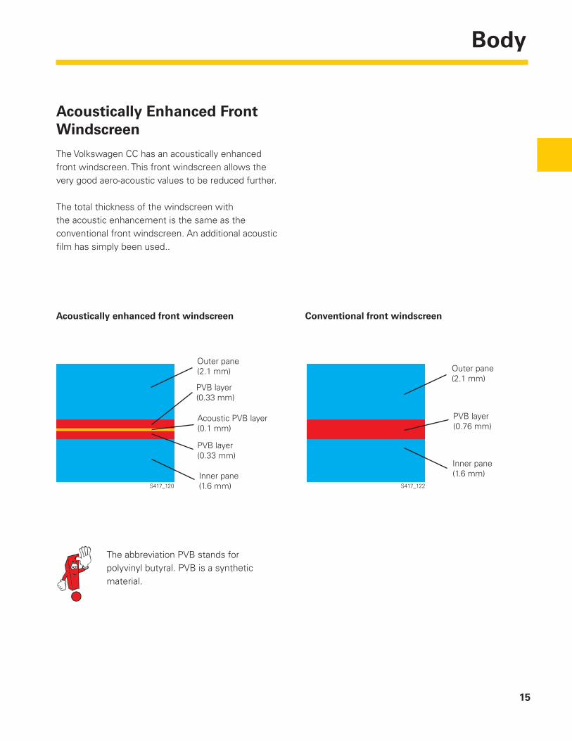
The Volkswagen CC has an acoustically enhanced front windscreen. This front windscreen allows the very good aero-acoustic values to be reduced further.
The total thickness of the windscreen with the acoustic enhancement is the same as the conventional front windscreen. An additional acoustic fi lm has simply been used..
Acoustically enhanced front windscreen Conventional front windscreen
Outer pane(2.1 mm)
PVB layer(0.33 mm)
Acoustic PVB layer(0.1 mm)
PVB layer(0.33 mm)
Inner pane(1.6 mm)
Outer pane(2.1 mm)
PVB layer(0.76 mm)
Inner pane(1.6 mm)
S417_120 S417_122
The abbreviation PVB stands for polyvinyl butyral. PVB is a synthetic material.

16
BodyControls
Rear Seats
The rear seats in the CC are a fi xed full seat bench with two seats. A storage compartment has been integrated in the area between the seating surfaces.
The armrest also has a storage compartment.
A lockable through-load opening is available as an option
S417_124
S417_130

Page intentionally left blank
18
Occupant Protection
Safety Equipment
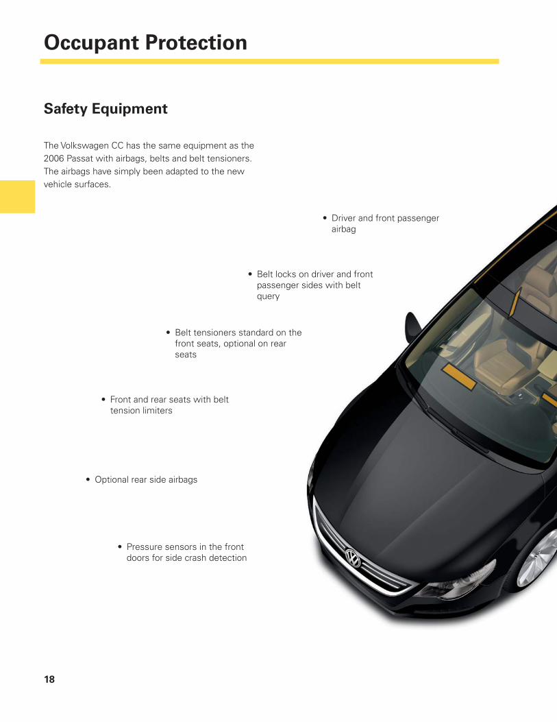
The Volkswagen CC has the same equipment as the 2006 Passat with airbags, belts and belt tensioners. The airbags have simply been adapted to the new vehicle surfaces.
Driver and front passenger • airbag
Belt locks on driver and front • passenger sides with belt query
Belt tensioners standard on the • front seats, optional on rear seats
Front and rear seats with belt • tension limiters
Optional rear side airbags•
Pressure sensors in the front • doors for side crash detection

19
Occupant Protection
Top Tether
The CC is equipped with a standard Top-Tether system. The Top-Tether system is used for additional child seat anchoring on the rear seat bench and is located in the rear parcel shelf.
S417_166
S417_168
S417_112
Side curtain airbags•
Two acceleration sensors in the vehicle • longitudinal direction of the airbag control module, one acceleration sensor in vehicle crossways direction in airbag control module
Two acceleration sensors for side crash detection • in the C-Pillar area
20
Engines
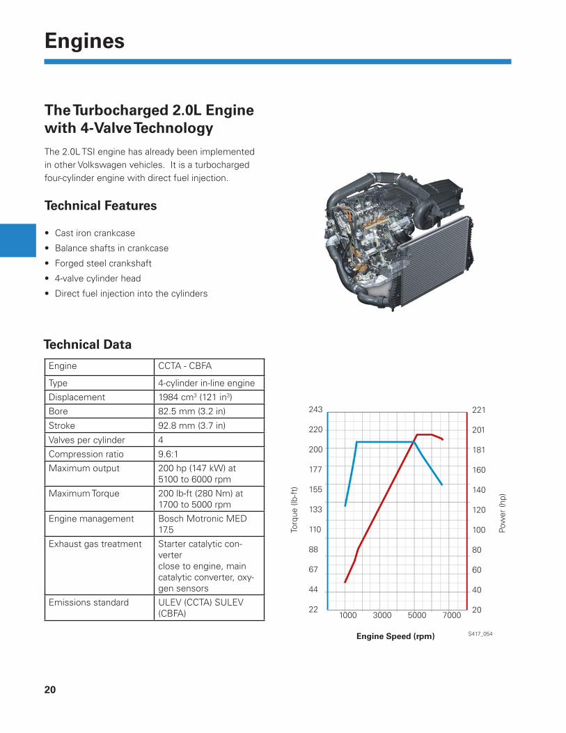
The Turbocharged 2.0L Engine with 4-Valve TechnologyThe 2.0L TSI engine has already been implemented in other Volkswagen vehicles. It is a turbocharged four-cylinder engine with direct fuel injection.
Technical Features
Cast iron crankcase•
Balance shafts in crankcase •
Forged steel crankshaft•
4-valve cylinder head•
Direct fuel injection into the cylinders •
243
220
200
177
155
133
110
88
67
44
22
221
201
181
160
140
120
100
80
60
40
20 1000 3000 5000 7000
S417_054Engine Speed (rpm)
Torq
ue (l
b-ft
)
Pow
er (h
p)
Engine CCTA - CBFA
Type 4-cylinder in-line engine
Displacement 1984 cm3 (121 in3)
Bore 82.5 mm (3.2 in)
Stroke 92.8 mm (3.7 in)
Valves per cylinder 4
Compression ratio 9.6:1
Maximum output 200 hp (147 kW) at5100 to 6000 rpm
Maximum Torque 200 lb-ft (280 Nm) at1700 to 5000 rpm
Engine management Bosch Motronic MED 17.5
Exhaust gas treatment Starter catalytic con-verterclose to engine, main catalytic converter, oxy-gen sensors
Emissions standard ULEV (CCTA) SULEV (CBFA)
Technical Data
21
Engines
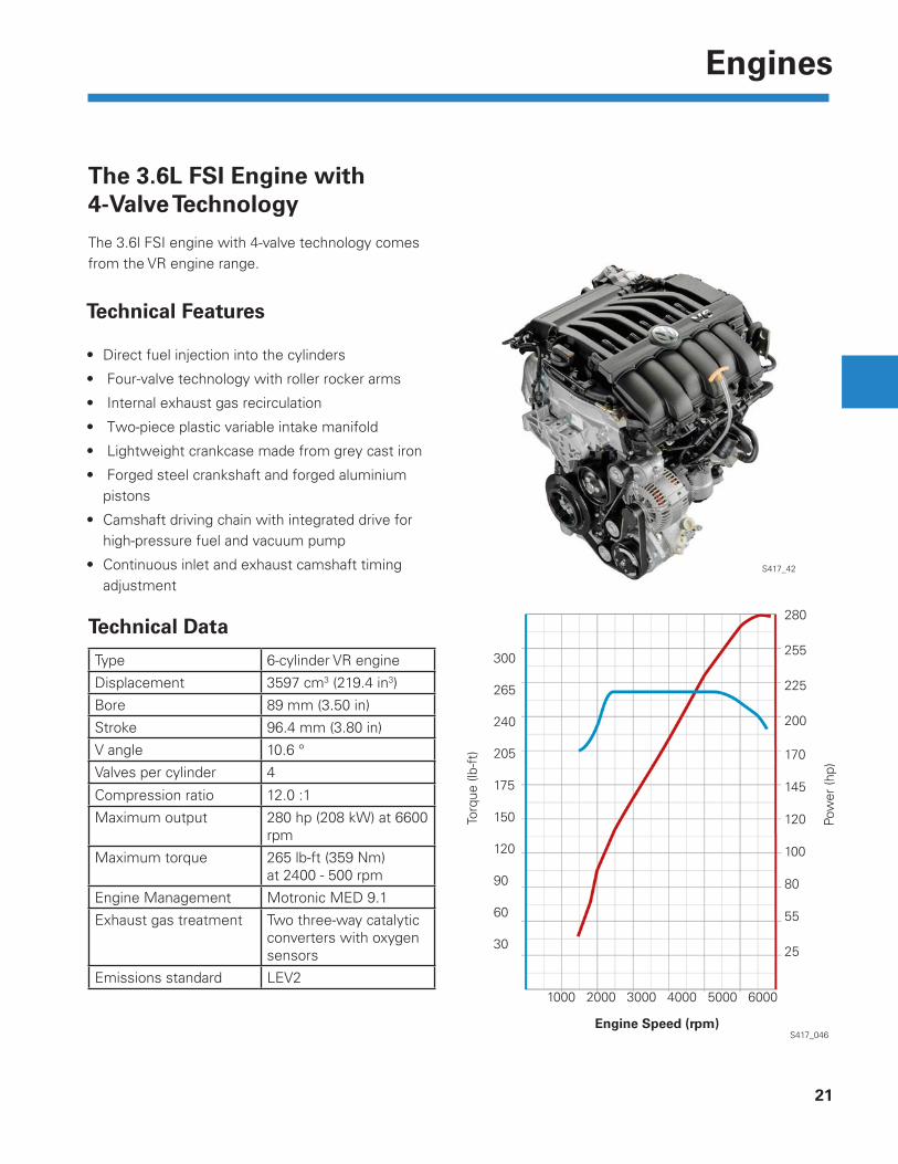
The 3.6L FSI Engine with 4-Valve Technology
The 3.6l FSI engine with 4-valve technology comes from the VR engine range.
Technical Features
Direct fuel injection into the cylinders •
Four-valve technology with roller rocker arms•
Internal exhaust gas recirculation•
Two-piece plastic variable intake manifold•
Lightweight crankcase made from grey cast iron•
Forged steel crankshaft and forged aluminium • pistons
Camshaft driving chain with integrated drive for • high-pressure fuel and vacuum pump
Continuous inlet and exhaust camshaft timing • adjustment
S417_42
Torq
ue (l
b-ft
)
300
265
240
205
175
150
120
90
60
30
280
255
225
200
170
145
120
100
80
55
25
1000 2000 3000 4000 5000 6000
S417_046
Pow
er (h
p)
Technical Data
Type 6-cylinder VR engine
Displacement 3597 cm3 (219.4 in3)
Bore 89 mm (3.50 in)
Stroke 96.4 mm (3.80 in)
V angle 10.6 °
Valves per cylinder 4
Compression ratio 12.0 :1
Maximum output 280 hp (208 kW) at 6600 rpm
Maximum torque 265 lb-ft (359 Nm)at 2400 - 500 rpm
Engine Management Motronic MED 9.1
Exhaust gas treatment Two three-way catalytic converters with oxygen sensors
Emissions standard LEV2
Engine Speed (rpm)

22
Chassis
Overview of ChassisThe chassis of the Volkswagen CC is essentially based on the chassis of the 2006 Passat. By using the modern McPherson strut front suspension, the four-link rear axle, the electromechanical steering with parallel-axis drive from the Tiguan and the electromechanical parking brake, this vehicle has thoroughly tested technology.
Safety steering column with electrical steering • column lock
Lightweight strut front axle•
ABS/ESP from TRW, EBC 440•
Electromechanical power • steering with parallel axis drive

23
Chassis
Four-link rear axle•
AUTO HOLD function•
S417_144
Electromechanical parking • brake with planetary gear

Page intentionally left blank
25
Electronics
S417_092
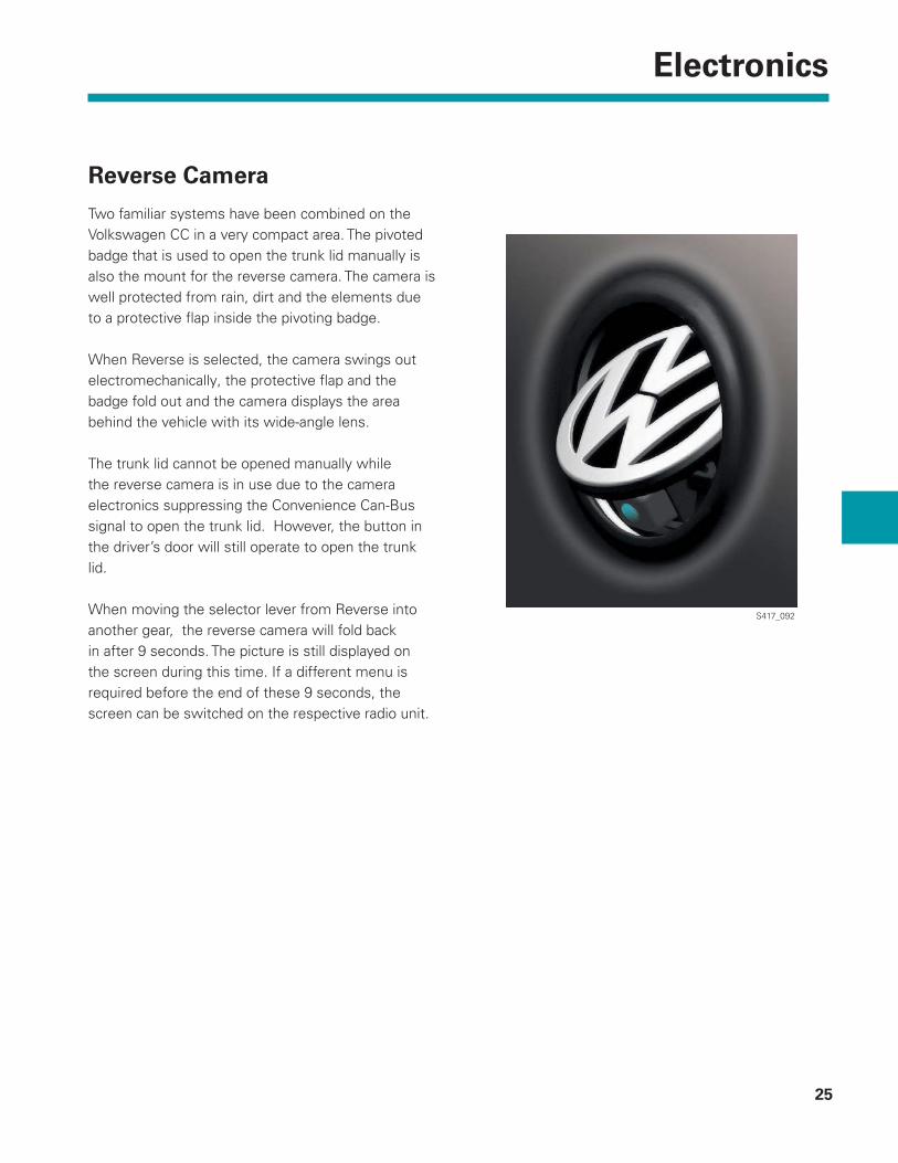
Reverse Camera
Two familiar systems have been combined on the Volkswagen CC in a very compact area. The pivoted badge that is used to open the trunk lid manually is also the mount for the reverse camera. The camera is well protected from rain, dirt and the elements due to a protective fl ap inside the pivoting badge.
When Reverse is selected, the camera swings out electromechanically, the protective fl ap and the badge fold out and the camera displays the area behind the vehicle with its wide-angle lens.
The trunk lid cannot be opened manually while the reverse camera is in use due to the camera electronics suppressing the Convenience Can-Bus signal to open the trunk lid. However, the button in the driver’s door will still operate to open the trunk lid.
When moving the selector lever from Reverse into another gear, the reverse camera will fold back in after 9 seconds. The picture is still displayed on the screen during this time. If a different menu is required before the end of these 9 seconds, the screen can be switched on the respective radio unit.

26
Electronics
Reverse Camera System Control Unit
The reverse camera system control unit has the task of processing the images supplied by the camera and preparing them for output on the display screen of the radio or radio/navigation system. This includes rectifying the supplied image and adding the static and dynamic helper lines that depict the vehicle with and without steering wheel turn. Two parking modes are available for the Volkswagen CC:
- reverse parking in “parking” mode and - parallel parking in “parallel” mode.
The mode should be selected using the buttons on the corresponding radio or radio/navigation system before the parking procedure is started.
“Parking” Mode
S417_242
“Parallel Mode
S417_244

27
Electronics
Reverse Camera System
The reverse camera system supports the driver while in Reverse by showing the driver the traffi c situation behind the vehicle on a screen.
The reverse camera system consists of the following components:
reverse camera,•
reverse camera system control unit and•
display screen (e.g. radio or radio/navigation • system with reverse camera input).
G85 Steering angle sensorJ519 Vehicle electrical system control moduleJ527 Steering column electronical systems control ModuleJ533 Data bus on board diagnostic interfaceJ772 Rear view camera system control moduleR189 Rear view camera
S417_193
Legend
Design
R189
J533
J527
J519
J772
G85
Video Signal Video Signal
Display on respective radio or radio/navigation system
Infotainment CAN Data Bus
Convenience CAN Data Bus

28
Electronics
Multifunction Steering Wheel
A new multifunction steering wheel is being used in the Volkswagen CC. The familiar horn button and the integrated driver airbag unit are located in the center of the multifunction steering wheel. There are now six instead of four multifunction buttons on each side to increase user-friendliness. Also, the back function can be accessed at any time with a new button.
The 12 multi-function buttons are used to operate:
- the radio or navigation unit, - the cruise control system
E439 E438
E440 E441
J453
LIN
LIN
J527F350
Convenience CAN Data Bus S417_252
S417_146
There are two more controls on the back of the multi-function steering wheel in the form of paddles. If the car has an automatic or DSG gearbox, these buttons can be used to select the gear.
The electrical connection between the steering wheel electronics and the onboard supply is formed by a coil connector in the steering wheel. Data is transferred between the two components via the LIN data bus.
Legend
E438 - Tiptronic upshift button (on steering wheel)E439 - Tiptronic downshift button(on steering wheel)E440 - Left multi-function button (on steering wheel)E441 - Right multi-function button (on steering wheel)F350 - Spiral spring J453 - Multi-function steering wheel control module J527 - Steering column electronic system control module

29
Electronics
Button Assignment
Left Buttons
Right Buttons
Shift Down Gear
Telephone
Increase Volume
Decrease Volume
Switch Back through Stations
Switch Forward through Stations
Speech Control/ Mute
Shift Up Gear and Return to Automatic Mode
Back
Main Menu Forward
Confi rm
Menu Down
Main Menu Backwards
Menu Up
S417_248
S417_250

30
Electronics
Optical Parking System
The optical parking system (OPS) is available for the Volkswagen CC. It is a software expansion for the parking aid system.
The park distance control system uses ultrasound sensors and an acoustic warning to help the driver determine the distance from other parked cars or obstacles. Only the warning from the sensor closest to the obstacle is supplied.
The optical parking system does not just detect obstacles in front of or behind the vehicle, but also detects its position in the scanning area. Now the driver is supported not only acoustically, but also optically. During the parking maneuver, OPS displays a diagram of the vehicle surrounded by colored areas on the radio or navigation system screen. These colored areas show the exact position and distance of obstacles for the driver. The OPS allows a low-cost graphic display to be provided without discrete display elements (e.g. LED bar). The driver can quickly detect the position of the obstacles and navigate more precisely. The picture is switched off above 15km/h (10 mph).
S417_181
S417_179
31
Electronics
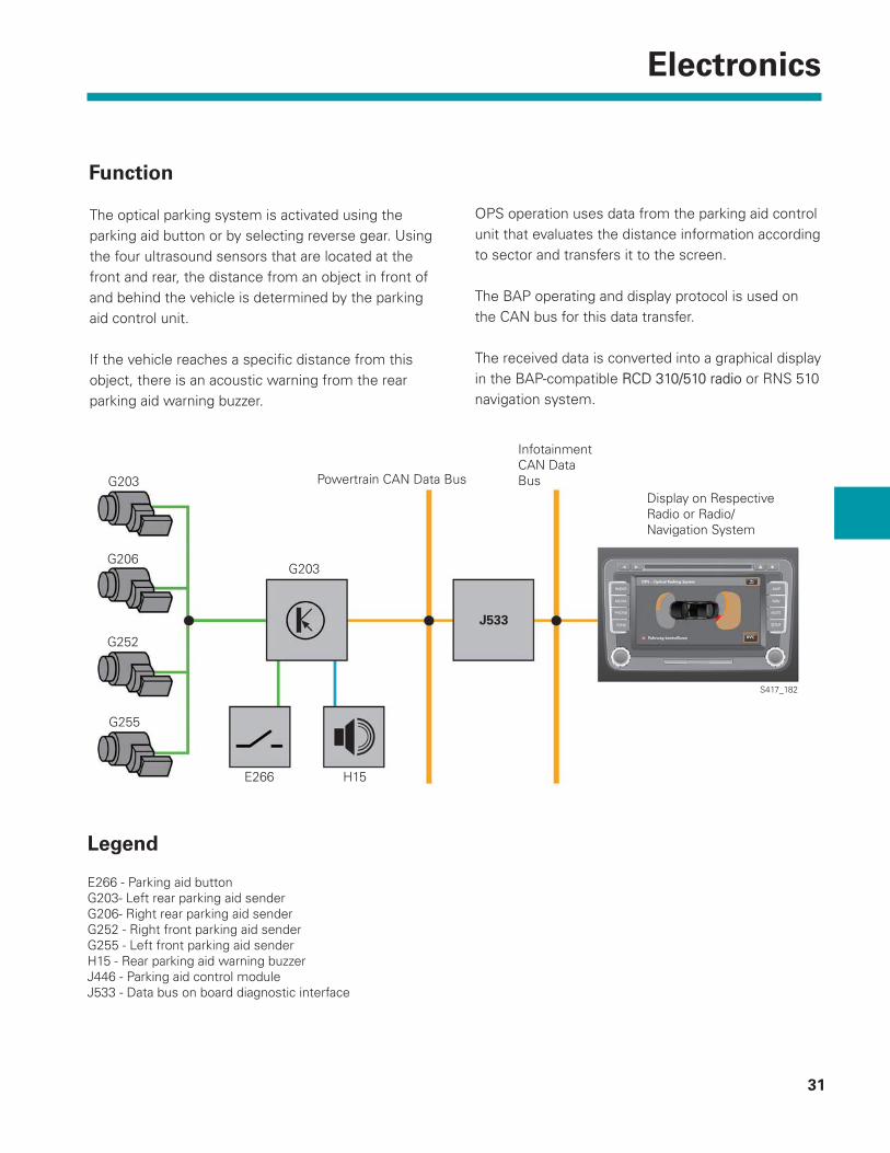
The optical parking system is activated using the parking aid button or by selecting reverse gear. Using the four ultrasound sensors that are located at the front and rear, the distance from an object in front of and behind the vehicle is determined by the parking aid control unit.
If the vehicle reaches a specifi c distance from this object, there is an acoustic warning from the rear parking aid warning buzzer.
OPS operation uses data from the parking aid control unit that evaluates the distance information according to sector and transfers it to the screen.
The BAP operating and display protocol is used on the CAN bus for this data transfer.
The received data is converted into a graphical display in the BAP-compatible RCD 310/510 radioRCD 310/510 radio or RNS 510 navigation system.
Function
Legend
E266 - Parking aid button G203- Left rear parking aid sender G206- Right rear parking aid sender G252 - Right front parking aid sender G255 - Left front parking aid sender H15 - Rear parking aid warning buzzer J446 - Parking aid control moduleJ533 - Data bus on board diagnostic interface
G203
J533
G203
H15E266
G255
G252
G206
S417_182
Powertrain CAN Data Bus
Infotainment CAN Data Bus
Display on Respective Radio or Radio/Navigation System

Page intentionally left blank

33
Radio and Navigation
The ID3 tag is additional information that can be contained in MP3 audio fi les. ID3 stands for “Identify an MP3”. “Tag” is simply a label attached to the fi le. MP3 fi les can, but do not have to contain ID3 tags. The ID3 tag is part of the MP3 fi le. The most important content of the ID3 tag is the artist, the name of the album and the name of the music track.
The Radio Systems in the Volkswagen CC
RCD 310 radio
FSTN monochrome display, (FSTN=Film-Super-• Twisted-Nematic, i.e. liquid crystal display)
Twin tuner with phase diversity•
Integrated DAB tuner (digital radio) (depending on • equipment)
Integrated CD drive•
Media support for MP3 and WMA audio data (with • ID3-Tag)
Optical parking system (OPS)•
Climate control information•
GALA speed-dependent volume control•
S417_184
S417_218
34
Radio and Navigation
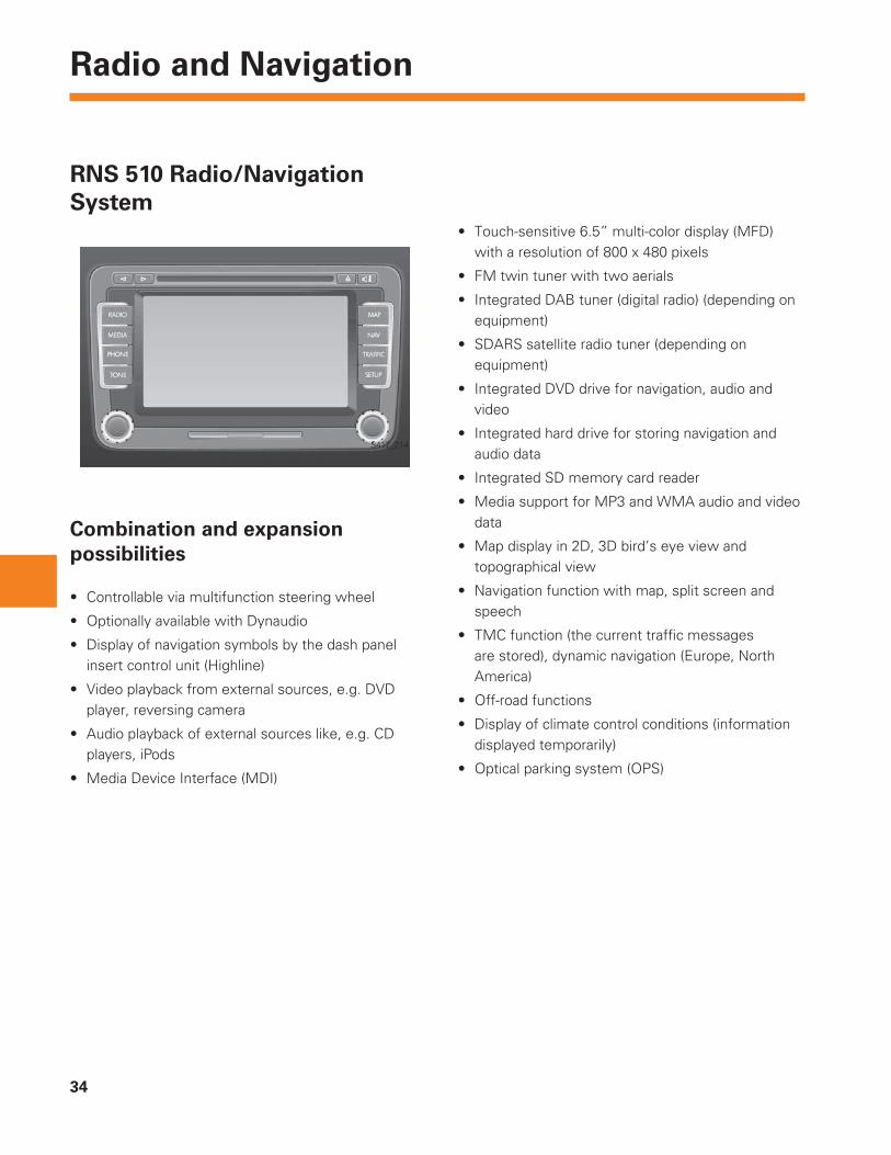
RNS 510 Radio/Navigation System
S417_214
Touch-sensitive 6.5” multi-color display (MFD) • with a resolution of 800 x 480 pixels
FM twin tuner with two aerials•
Integrated DAB tuner (digital radio) (depending on • equipment)
SDARS satellite radio tuner (depending on • equipment)
Integrated DVD drive for navigation, audio and • video
Integrated hard drive for storing navigation and • audio data
Integrated SD memory card reader•
Media support for MP3 and WMA audio and video • data
Map display in 2D, 3D bird’s eye view and • topographical view
Navigation function with map, split screen and • speech
TMC function (the current traffi c messages • are stored), dynamic navigation (Europe, North America)
Off-road functions•
Display of climate control conditions (information • displayed temporarily)
Optical parking system (OPS)•
Combination and expansion possibilities
Controllable via multifunction steering wheel•
Optionally available with Dynaudio•
Display of navigation symbols by the dash panel • insert control unit (Highline)
Video playback from external sources, e.g. DVD • player, reversing camera
Audio playback of external sources like, e.g. CD • players, iPods
Media Device Interface (MDI)•

35
Radio and Navigation
Aerial Concept in Volkswagen CC
Several aerials are integrated in the rear window of the Volkswagen CC. The aerial for navigation (GPS) are integrated in a roof aerial.
The negative blocking circuit is connected directly to the negative connection of the rear windscreen heating (right). The positive blocking circuit is in the supply cable of the rear windscreen heating connection (left). As the aerial structure for AM does not have a connection to the heating structure, an AM blocking circuit is not required.
+ Blocking Circuit is Incorporated in the Supply Line to the Rear Windscreen Heating
S417_172
DAB/FM2 Impedance Transformer
Rear Windscreen Heating Voltage Supply
DAB AerialsFM1 AerialAM Aerial
FM2 Aerial
Diagnosis Jumper Diagnosis Jumper
AM/FM1 Impedance Transformer
- Blocking Circuit on Heating Connection

36
Radio and Navigation
Media Device Interface Box
The media device interface, or MDI for short, allows passengers in the Volkswagen CC to connect their mobile audio or multimedia devices (e.g. iPod, MP3 players or USB sticks) to the infotainment system and display, select and play the audio content over the vehicle speaker system or the infotainment monitors.
Location
The MDI control unit is accommodated in a plastic case of the MDI box. The MDI box is DIN sized and has a safe anti-slip area to place the mobile multimedia device. The MDI box is fi tted in space for the CD changer. .
S417_226
S417_224
MDI Control Unit
MDI Control UnitMDI Box
MDI Box
Storage Compartment
Adapter Connection

37
Radio and Navigation
S417_228
S417_230
S417_222
Connection Possibilities
The mobile device is connected depending on the type with a special adapter cable that is connected to the central interface, the adapter connection. The following audio formats are currently supported and can be played back: MP3, WMA and OGG Vorbis (license-free audio data compression Codec). The AAC format that is also supported is a licensed format from Apple.
Connection possibilities with USB adapter cable
Connection possibilities with mini USB adapter cable
Connection possibilities with adapter cable for iPod
USB sticks, MP3 player and USB hard drives can be connected via the USB adapter cable.
MP3 players, telephone/communicators and Mini-USB hard drives can be connected via the mini USB adapter cable.
Different iPods can be connected via the adapter cable for iPod.
On the display unit, which has to support the operating and display protocol (BAP), the same audio playback lists are shown as on the iPod.

38
Radio and Navigation
The Media Device Interface (MDI) is an interface control unit for connecting a wide range of media devices to the vehicle’s infotainment network.
As an interface control unit, the MDI has to ensure that the media unit is adapted to the vehicle infotainment system both on the physical side (connector compatibility) and also by the software. Furthermore the infotainment system has to be informed by the MDI that a new data memory is available from which music can be read and played back.
Finally the MDI should allow the recognized unit to be controlled via the radio or radio/navigation system.
Task
+12V, Ground
RCD/RNS
LF
MDI Box
If only the AUX-IN socket is fi tted in the vehicle, it is connected directly to the AUX input of the fi tted RCD/RNS radio or navigation system. If the vehicle also has a Media-Device-Interface, the optional AUX-IN socket is connected to the MDI box as the AUX input of the radio is already occupied by the MDI.
39
Radio and Navigation
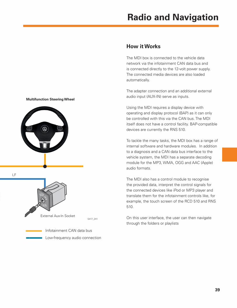
How it Works
The MDI box is connected to the vehicle data network via the infotainment CAN data bus and is connected directly to the 12-volt power supply. The connected media devices are also loaded automatically.
The adapter connection and an additional external audio input (AUX-IN) serve as inputs.
Using the MDI requires a display device with operating and display protocol (BAP) as it can only be controlled with this via the CAN bus. The MDI itself does not have a control facility. BAP-compatible devices are currently the RNS 510.
To tackle the many tasks, the MDI box has a range of internal software and hardware modules. In addition to a diagnosis and a CAN data bus interface to the vehicle system, the MDI has a separate decoding module for the MP3, WMA, OGG and AAC (Apple) audio formats.
The MDI also has a control module to recognise the provided data, interpret the control signals for the connected devices like iPod or MP3 player and translate them for the infotainment controls like, for example, the touch screen of the RCD 510 and RNS 510.
On this user interface, the user can then navigate through the folders or playlists
LF
External Aux-In Socket
Multifunction Steering Wheel
S417_241
Infotainment CAN data bus
Low-frequency audio connection

40
Heating and Air Conditioning
Air Conditioning
S417_159
Two different types of air-conditioning system are available in the Volkswagen CC that have also already been used in the 2006 Passat:
The semi-automatic heater and air conditioner “Climatic”•
The fully automatic “2C-Climatronic” heating and air-conditioning system•
Operation
New controls are being used depending on the equipment fi tted:
with and without button for seat heating•
with or without button for heated rear window•

41
Heating and Air Conditioning
Climatic
Controls
Rear Window HeatingRecirculate Button
Feedback LED
AC Button
Electronic Rotary Knob for Air Distribution
Button for Seat Heating, Right
S417_161
Button for Seat Heating, Left
Electronic Temperature Rotary Knob
Air-Conditioning Unit
The fl aps for air distribution are no longer adjusted via a fl exible shaft, but via an electrically operated control motor.
Curve Disc Left
Air Distribution Flaps
Control Motor
Curve Disc Right
S417_163
42
Heating and Air Conditioning
Climatronic
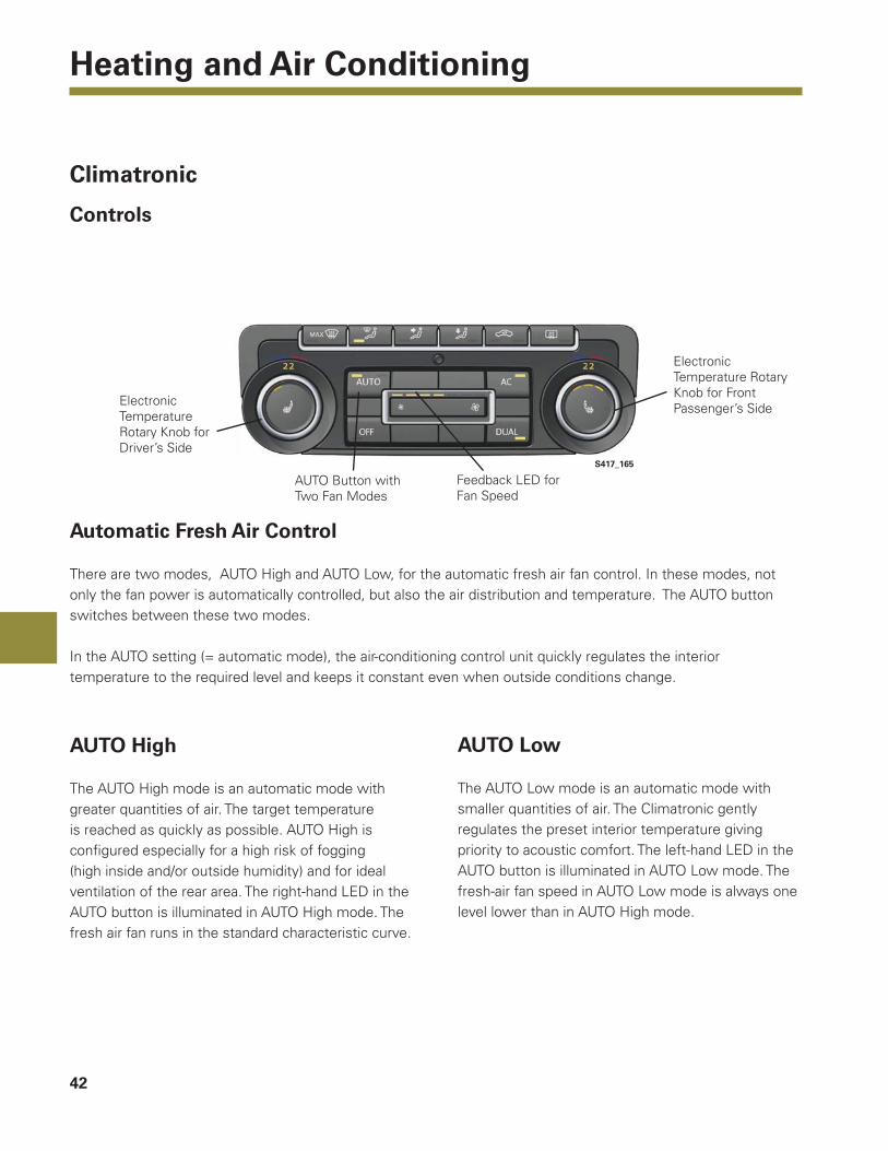
Controls
S417_165
Automatic Fresh Air Control
There are two modes, AUTO High and AUTO Low, for the automatic fresh air fan control. In these modes, not only the fan power is automatically controlled, but also the air distribution and temperature. The AUTO button switches between these two modes.
In the AUTO setting (= automatic mode), the air-conditioning control unit quickly regulates the interior temperature to the required level and keeps it constant even when outside conditions change.
AUTO High
The AUTO High mode is an automatic mode with greater quantities of air. The target temperature is reached as quickly as possible. AUTO High is confi gured especially for a high risk of fogging (high inside and/or outside humidity) and for ideal ventilation of the rear area. The right-hand LED in the AUTO button is illuminated in AUTO High mode. The fresh air fan runs in the standard characteristic curve.
AUTO Low
The AUTO Low mode is an automatic mode with smaller quantities of air. The Climatronic gently regulates the preset interior temperature giving priority to acoustic comfort. The left-hand LED in the AUTO button is illuminated in AUTO Low mode. The fresh-air fan speed in AUTO Low mode is always one level lower than in AUTO High mode.
Electronic Temperature Rotary Knob for Driver’s Side
AUTO Button with Two Fan Modes
Feedback LED for Fan Speed
Electronic Temperature Rotary Knob for Front Passenger’s Side
43
Heating and Air Conditioning
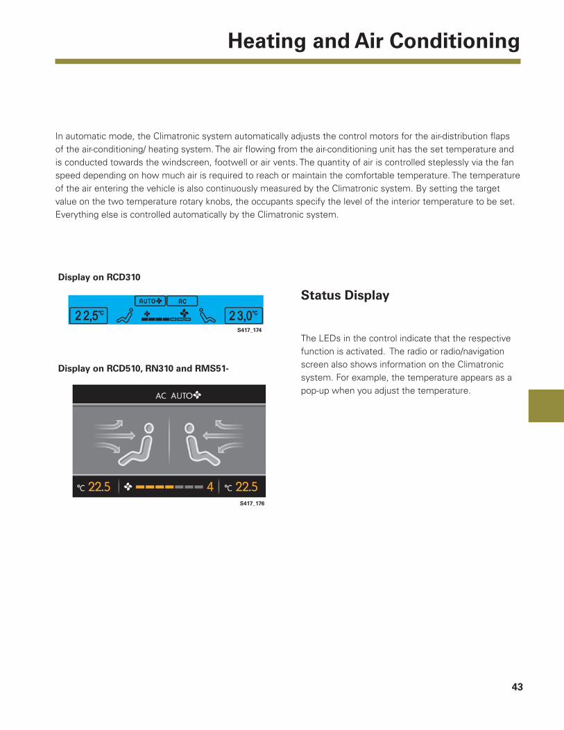
In automatic mode, the Climatronic system automatically adjusts the control motors for the air-distribution fl aps of the air-conditioning/ heating system. The air fl owing from the air-conditioning unit has the set temperature and is conducted towards the windscreen, footwell or air vents. The quantity of air is controlled steplessly via the fan speed depending on how much air is required to reach or maintain the comfortable temperature. The temperature of the air entering the vehicle is also continuously measured by the Climatronic system. By setting the target value on the two temperature rotary knobs, the occupants specify the level of the interior temperature to be set. Everything else is controlled automatically by the Climatronic system.
S417_174
S417_176
Display on RCD310
Display on RCD510, RN310 and RMS51-
Status Display
The LEDs in the control indicate that the respective function is activated. The radio or radio/navigation screen also shows information on the Climatronic system. For example, the temperature appears as a pop-up when you adjust the temperature.

44
Electrical
Fuse Boxes and Relay Locations in the Onboard Supply
Locations
The battery is located on the left of the engine compartment or on the left of the luggage compartment depending on the equipment version.
Fuse and relay box, left of engine compartment
Additional relay carrier under the fuse and relay box
Back-up fuse box on left of engine compartment
45
Electrical
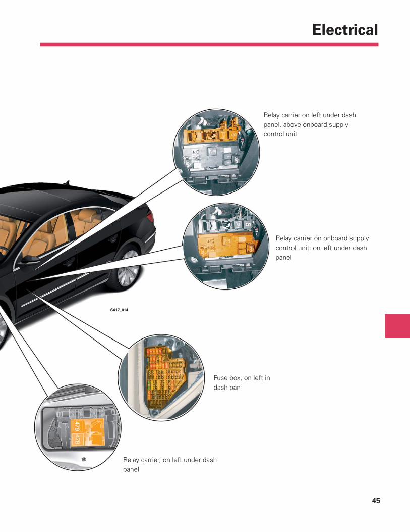
Relay carrier on onboard supply control unit, on left under dash panel
Fuse box, on left in dash pan
Relay carrier, on left under dash panel
Relay carrier on left under dash panel, above onboard supply control unit
S417_014

46
Electrical
J428
G197
J772
R215
R190**
J387 J389
J386 J388
J519J525
J354J503, R
J533 J245
J668J667
J285
T16
J788
J745
J623
J769
J770
B
A
C
The data bus on board diagnostic interface J533 forms the interface for communication between the following data bus systems:
- Powertrain CAN data bus- Convenience CAN data bus- Infotainment CAN data bus- Cluster CAN data bus- Diagnostics CAN data bus
The following data bus systems are connected downstream of a CAN data bus system as sub-bus systems:
- LIN data buses- Sensor CAN data bus - Cornering light CAN data bus - Lane change assist CAN data bus- Serial data bus
Networking Concept
Powertrain CAN data busConvenience CAN data busInfotainment CAN data busSensor CAN data busCluster CAN data busDiagnostics CAN data busLane change assist CAN data busCornering light CAN data busLIN data busCAN data bus lineLIN data bus lineCommunications lineSerial data bus cable
Legend
ABC
-----
47
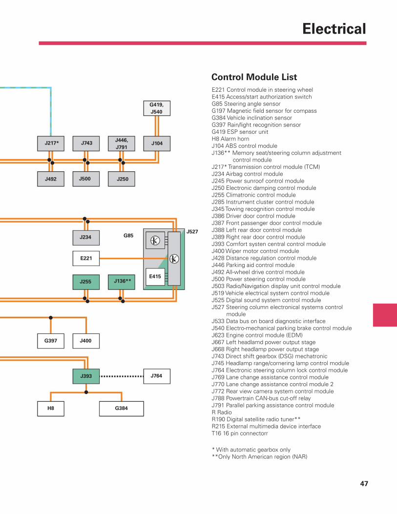
Electrical
J217* J104
G419, J540
J250
J446, J791
J743
J500J492
J527G85J234
E221
E415J136**J255
J400
J764J393
G384
G397
H8
Control Module ListE221 Control module in steering wheelE415 Access/start authorization switchG85 Steering angle sensorG197 Magnetic fi eld sensor for compassG384 Vehicle inclination sensorG397 Rain/light recognition sensorG419 ESP sensor unitH8 Alarm hornJ104 ABS control moduleJ136** Memory seat/steering column adjustment control moduleJ217* Transmission control module (TCM)J234 Airbag control moduleJ245 Power sunroof control moduleJ250 Electronic damping control moduleJ255 Climatronic control moduleJ285 Instrument cluster control moduleJ345 Towing recognition control moduleJ386 Driver door control moduleJ387 Front passenger door control moduleJ388 Left rear door control moduleJ389 Right rear door control moduleJ393 Comfort systen central control moduleJ400 Wiper motor control moduleJ428 Distance regulation control moduleJ446 Parking aid control moduleJ492 All-wheel drive control moduleJ500 Power steering control moduleJ503 Radio/Navigation display unit control moduleJ519 Vehicle electrical system control moduleJ525 Digital sound system control moduleJ527 Steering column electronical systems control moduleJ533 Data bus on board diagnostic interfaceJ540 Electro-mechanical parking brake control moduleJ623 Engine control module (EDM)J667 Left headlamd power output stageJ668 Right headlamp power output stageJ743 Direct shift gearbox (DSG) mechatronicJ745 Headlamp range/cornering lamp control moduleJ764 Electronic steering column lock control moduleJ769 Lane change assistance control moduleJ770 Lane change assistance control module 2J772 Rear view camera system control moduleJ788 Powertrain CAN-bus cut-off relayJ791 Parallel parking assistance control moduleR RadioR190 Digital satellite radio tuner**R215 External multimedia device interfaceT16 16 pin connectorr
* With automatic gearbox only**Only North American region (NAR)

48
Glossary
AM
Amplitude modulation, electromagnetic wave used to transmit messages. In amplitude modulation, the amplitude of the high frequency is varied.
BAP
The BAP operating and display protocol is used for communication between function control units and operating and display control units. BAP specifi cally separates the function from the display and the control.
FM
Frequency modulation, electromagnetic wave used to transmit messages. In frequency modulation, the frequency of the carrier wave varies in step with the information signal. The amplitude remains constant.
GPS
Global Positioning System, a satellite system set up by the US Department of Defense that aids navigation.
GSM
Global System for Mobile communications Standard for digital mobile telecommunications networks that is also used for data transfer as well as text messages (SMS).
MP3
Motion Pictures expert group layer 3 (MPEG Layer 3) Compression standards for video, audio and image formats.
NAR
North American Region
LF
Low frequency
RDS
Radio Data SystemStandardised system for transferring non-audio additional information for radio e.g. station names, audio titles etc.
SD
Secure Digital cardSmall and robust memory cards, e.g. for digital photo, MP3 players etc.
SDARS
Satellite Digital Audio Radio ServicesA digital radio standard for commercial satellite radio in North America.
TFT
Thin Film Transistor Display(TFT display = fl at screen).
TMC
Traffi c Message ChannelA digital service in radio for transmission of traffi c messages

49
Glossary
USB
Universal Serial Bus.Universal serial interface between different computers and peripheral devices.
WMA
Windows Media AudioSpecial audio format under Microsoft Windows.

Page intentionally left blank
51
Knowledge Assessment
An on-line Knowledge Assessment (exam) is available for this Self-Study Program.
The Knowledge Assessment may or may not be required for Certifi cation.
You can fi nd this Knowledge Assessment at:
www.vwwebsource.com
For Assistance, please call:
Volkswagen Academy
Certifi cation Program Headquarters
1-877-491-4838
(8:00 a.m. to 8:00 p.m. EST)
Or, E-Mail:
Volkswagen Group of America2200 Ferdinand Porsche DriveHerndon, VA 20171October, 2008