Self-Study Program 894803
56
Service Training Self-Study Program 894803 The 2008 Touareg 2
Transcript of Self-Study Program 894803

Service Training
Self-Study Program 894803
The 2008 Touareg 2
Volkswagen Group of America, Inc.Volkswagen AcademyPrinted in U.S.A.Printed 10/2008Course Number 894803
©2008 Volkswagen Group of America, Inc.
All rights reserved. All information contained in this manual is based on the latest information available at the time of printing and is subject to the copyright and other intellectual property rights of Volkswagen Group of America, Inc., its affi liated companies and its licensors. All rights are reserved to make changes at any time without notice. No part of this document may be reproduced,stored in a retrieval system, or transmitted in any form or by any means, electronic, mechanical, photocopying, recording or otherwise, nor may these materials be modified or reposted to other sites without the prior expressed written permission ofthe publisher.
All requests for permission to copy and redistribute information should be referred to Volkswagen Group of America, Inc.
Always check Technical Bulletins and the latest electronic repair information for information that may supersede any information included in this booklet.
Trademarks: All brand names and product names used in this manual are trade names, service marks, trademarks, or registered trademarks; and are the property of their respective owners.
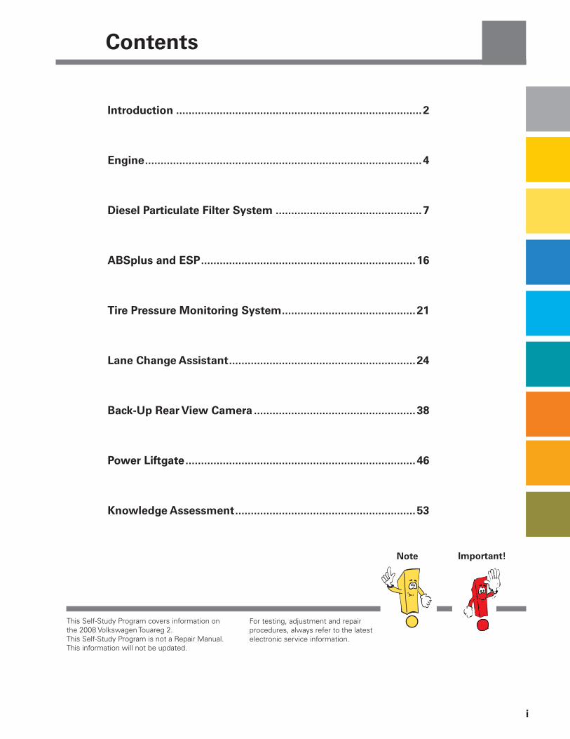
Introduction ...............................................................................2
Engine .........................................................................................4
Diesel Particulate Filter System ...............................................7
ABSplus and ESP .....................................................................16
Tire Pressure Monitoring System ...........................................21
Lane Change Assistant ............................................................24
Back-Up Rear View Camera ....................................................38
Power Liftgate ..........................................................................46
Knowledge Assessment ..........................................................53
This Self-Study Program covers information on the 2008 Volkswagen Touareg 2.This Self-Study Program is not a Repair Manual. This information will not be updated.
For testing, adjustment and repair procedures, always refer to the latest electronic service information.
Contents
i
Note Important!

2
Introduction
Volkswagen Bratislava, s.r.o. was founded in 1991 as a joint project of Bratislavaer Automobilwerken, a.s. and Volkswagen AG. The factory employs approximately 8,400 people. The grounds extend to almost 450 acres. In addition to producing the Touareg, the Bratislava plant also produces the Audi Q7 and the VW Polo. Its output in 2006 totaled more than 238,000 vehicles.
The Volkswagen Touareg is produced at Volkswagen Bratislava, s.r.o. in Bratislava, Slovakia. Over 250,000 Touaregs have been produced since its introduction.
3
Introduction
3
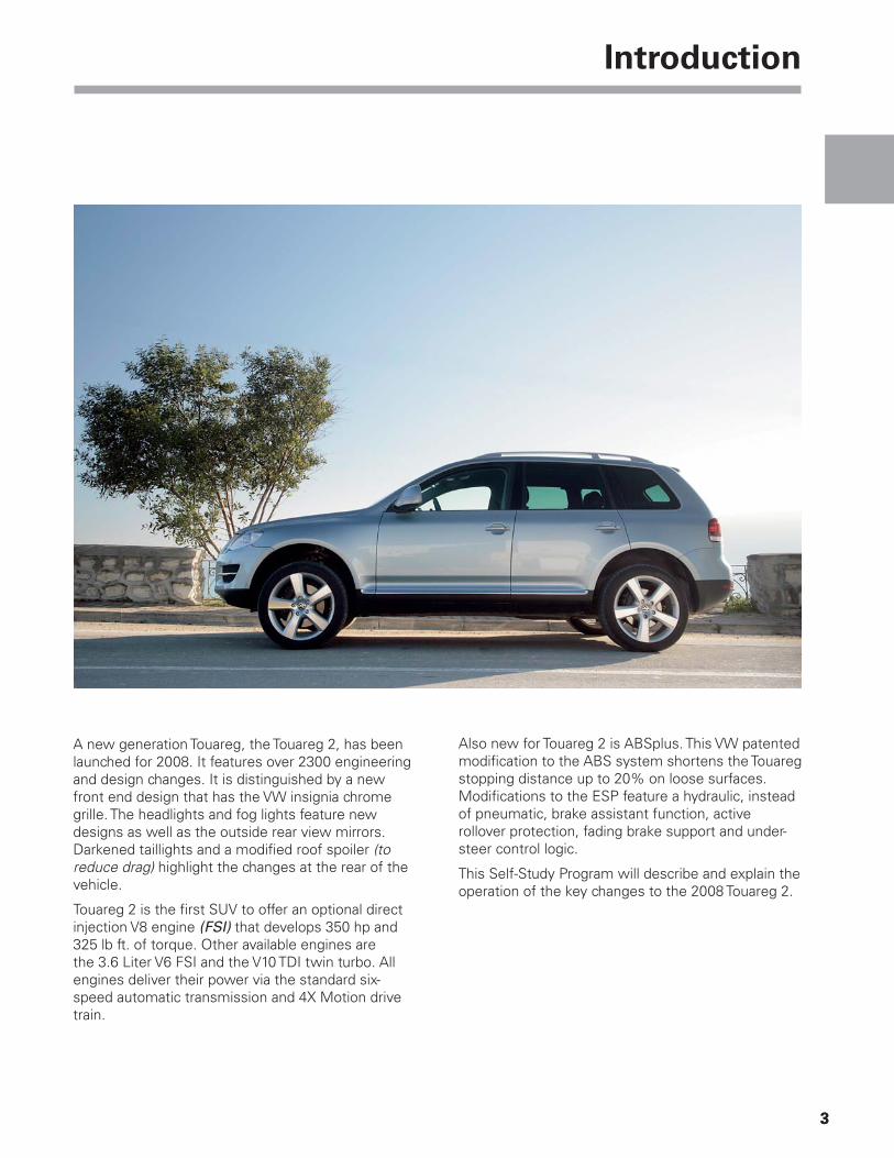
A new generation Touareg, the Touareg 2, has been launched for 2008. It features over 2300 engineering and design changes. It is distinguished by a new front end design that has the VW insignia chrome grille. The headlights and fog lights feature new designs as well as the outside rear view mirrors. Darkened taillights and a modifi ed roof spoiler (to reduce drag) highlight the changes at the rear of the vehicle.
Touareg 2 is the fi rst SUV to offer an optional direct injection V8 engine (FSI) that develops 350 hp and 325 lb ft. of torque. Other available engines are the 3.6 Liter V6 FSI and the V10 TDI twin turbo. All engines deliver their power via the standard six-speed automatic transmission and 4X Motion drive train.
Also new for Touareg 2 is ABSplus. This VW patented modifi cation to the ABS system shortens the Touareg stopping distance up to 20% on loose surfaces. Modifi cations to the ESP feature a hydraulic, instead of pneumatic, brake assistant function, active rollover protection, fading brake support and under-steer control logic.
This Self-Study Program will describe and explain the operation of the key changes to the 2008 Touareg 2.

Engine
4
3.6 L V6 FSI Engine
Horsepower: 280 hp (208 kW) @ 6200 rpm
Torque: 265 lb ft (360 Nm) @ 2500 – 5000 rpm
1.9 DEM cinortoM :tnemeganam enignE
Recommended fuel: RON 98
Exhaust gas treatment: Internal EGR, 3-way catalysts, Secondary air injection
4-2-6-3-5-1 :redro gniriF
1:21 :oitar noisserpmoC
4 :rednilyc rep sevlaV
Engine code: BHK
lanidutignol ,elgna V °6.01 ,6RV ,L 6.3 :ngiseD
Displacement: 219.5 cu in (3597 cc)
Bore: 3.50 in (89 mm)
Stroke: 3.79 in (96.4 mm)
II VEL :level snoissimE
Power in hp
Torque in lb ft
250
200
150
100
50
250
225
200
175
150
125
2000 4000 6000
torque hp
0 0
Engine
5
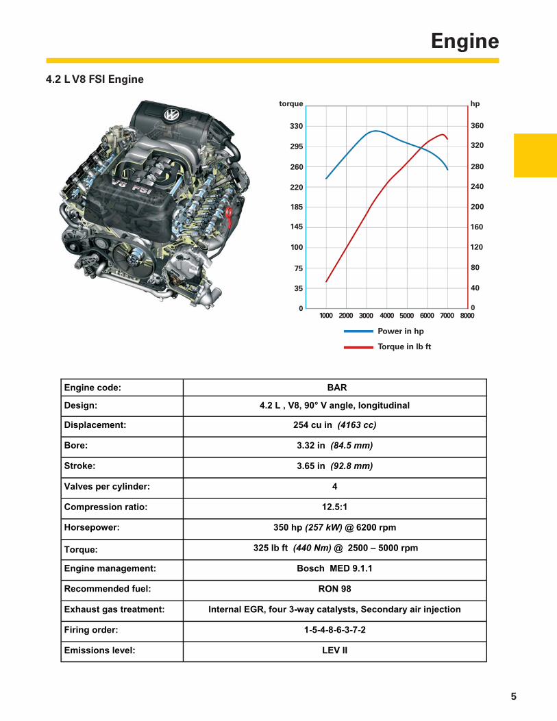
4.2 L V8 FSI Engine
Horsepower: 350 hp (257 kW) @ 6200 rpm
Torque: 325 lb ft (440 Nm) @ 2500 – 5000 rpm
1.1.9 DEM hcsoB :tnemeganam enignE
Recommended fuel: RON 98
Exhaust gas treatment: Internal EGR, four 3-way catalysts, Secondary air injection
2-7-3-6-8-4-5-1 :redro gniriF
1:5.21 :oitar noisserpmoC
4 :rednilyc rep sevlaV
Engine code: BAR
lanidutignol ,elgna V °09 ,8V ,L 2.4 :ngiseD
Displacement: 254 cu in (4163 cc)
Bore: 3.32 in (84.5 mm)
Stroke: 3.65 in (92.8 mm)
II VEL :level snoissimE
360
280
240
160
80
330
260
220
145
100
35
3000 5000 7000
torque hp
295
185
75
320
200
120
40
1000 2000 4000 6000 80000 0
Power in hp
Torque in lb ft
Engine
6
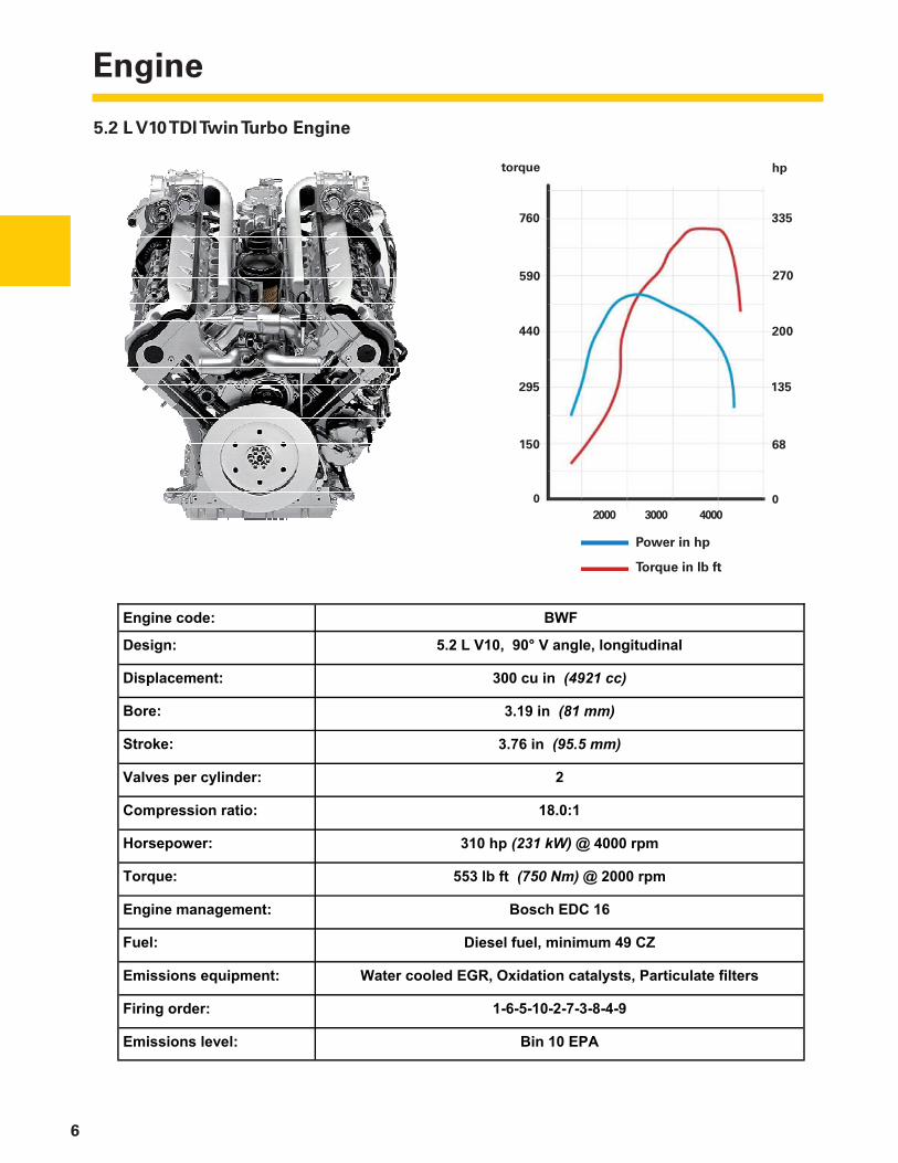
5.2 L V10 TDI Twin Turbo Engine
Horsepower: 310 hp (231 kW) @ 4000 rpm
Torque: 553 lb ft (750 Nm) @ 2000 rpm
61 CDE hcsoB :tnemeganam enignE
Fuel: Diesel fuel, minimum 49 CZ
Emissions equipment: Water cooled EGR, Oxidation catalysts, Particulate filters
9-4-8-3-7-2-01-5-6-1 :redro gniriF
1:0.81 :oitar noisserpmoC
2 :rednilyc rep sevlaV
Engine code: BWF
lanidutignol ,elgna V °09 ,01V L 2.5 :ngiseD
Displacement: 300 cu in (4921 cc)
Bore: 3.19 in (81 mm)
Stroke: 3.76 in (95.5 mm)
APE 01 niB :level snoissimE
335
270
200
135
68
760
590
440
295
150
2000 3000 4000
torque hp
0 0
Power in hp
Torque in lb ft
Diesel Particulate Filter System
7
The reduction of particulate emissions from diesel engines is a great challenge. In addition to engine design and operating parameters, exhaust gas treatments are of particular importance to help achieve this reduction.
The particulate fi lter is an effective method to remove carbon soot particles that are inherent in diesel emissions. The most common fi lter systems are comprised of an oxidation catalyst and a particulate fi lter.
For the catalytic coated particulate fi lter used on the Touareg 2 with the V10 TDI twin turbo engine, the catalyst and fi lter have been combined to form a single unit. With this particulate fi lter system, the particulates can be burned off continually without the addition of a fuel additive.
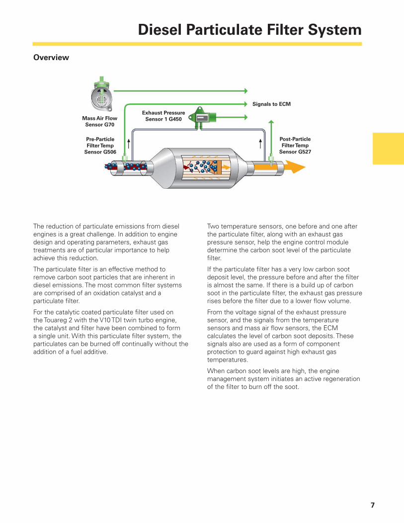
Two temperature sensors, one before and one after the particulate fi lter, along with an exhaust gas pressure sensor, help the engine control module determine the carbon soot level of the particulate fi lter.
If the particulate fi lter has a very low carbon soot deposit level, the pressure before and after the fi lter is almost the same. If there is a build up of carbon soot in the particulate fi lter, the exhaust gas pressure rises before the fi lter due to a lower fl ow volume.
From the voltage signal of the exhaust pressure sensor, and the signals from the temperature sensors and mass air fl ow sensors, the ECM calculates the level of carbon soot deposits. These signals also are used as a form of component protection to guard against high exhaust gas temperatures.
When carbon soot levels are high, the engine management system initiates an active regeneration of the fi lter to burn off the soot.
Overview
Mass Air Flow
Sensor G70
Pre-Particle
Filter Temp
Sensor G506
Post-Particle
Filter Temp
Sensor G527
Signals to ECM
Exhaust Pressure
Sensor 1 G450

Diesel Particulate Filter System
8
The catalytic coated diesel particulate fi lter is located in the exhaust system after the turbocharger, within close proximity of the engine. On the V10 TDI twin turbo engine, two mass airfl ow sensors, two turbochargers and two particulate fi lters are used.
This diesel particulate fi lter fi lters out the carbon soot particles from the exhaust gas.
In its function as oxidation catalyst, it cleans the exhaust gas of hydrocarbons (HC) and carbon monoxide (CO). They are converted into water (H2O) and carbon dioxide (CO2).
As mentioned, two components, the oxidation catalyst and the particulate fi lter, have been combined to form one unit — the catalytic coated diesel particulate fi lter. It joins the functions of the oxidation catalyst and the diesel particulate fi lter in one single component.
Catalytic Coated Diesel
Particulate Filter
Oxidation
Catalyst
Particle
Filter
Oxidation
Catalyst
Catalytic Coated Diesel
Particulate Filter

Diesel Particulate Filter System
9
Function
Since the channels are sealed alternately in the direction of fl ow from the inlet and outlet side, the carbon soot contaminated exhaust gas must fl ow through the porous fi lter walls made from silicon carbide. When this happens, the carbon soot particles and not the gaseous components are retained in the inlet channels.
Design
The diesel particulate fi lter is comprised of a honeycomb ceramic matrix made from silicon carbide placed in a metal housing. The ceramic matrix itself has many small channels that run parallel to each other and are alternately connected. In this way, inlet and outlet channels are created that are separated by fi lter walls.
The fi lter walls, made from silicon carbide, are porous. The silicon carbide body is coated with a mixture of aluminum oxide and peroxide.
This mixture serves as a carrier layer for the catalytic converter. The carrier layer is coated with the precious metal platinum, which acts as the catalyst. A catalyst is a substance that promotes or hinders a chemical reaction without changing itself.
Metal Housing
Honeycombed
Ceramic Matrix
Inlet Channel
Filter Wall
Soot Particles
Outer Channel
Outer Channel
Silicone Carbide Body
Carrier Layer
(Aluminum Oxide/
Ceroxide)
Soot Particles in
Inlet Channel
Platinum

Diesel Particulate Filter System
10
Coated Zones
The diesel particulate fi lter requires a specifi c length to provide a large storage volume for the carbon soot. In addition, it must be coated with a certain amount of platinum in order to attain the desired catalytic effect. The catalytic coating of the diesel particulate fi lter is separated into zones across the length of the fi lter.
In the front zone, there is a large quantity of platinum and in the rear zone there is less platinum. The following are advantages from the zone-like coating:
– In normal operating modes of the engine, the diesel particulate fi lter heats up quickly in the front area. Due to the high concentration of platinum in this front zone of the catalyst, the fi lter has a very fast catalytic effect. The diesel particulate fi lter responds quickly.
– In regeneration mode, the rear area of the diesel particulate fi lter becomes very hot as the carbon soot is burned off. Due to these high temperatures, the platinum gets broken down over a period of time. Therefore, expensive raw material is not used as intensively at the rear zone.
– Another reason for reduced use of platinum in the rear zone is the aging of the diesel particulate fi lter. During operation, more and more ash particulates from regeneration stay in the fi lter. These impair the catalytic effectiveness of the platinum.
Regeneration
The diesel particulate fi lter must be cleaned of carbon soot particles regularly to prevent it from becoming blocked, inhibiting its function. During the regeneration phase, the particulates that have accumulated in the particulate fi lter are burnt off (oxidized).
With regeneration of the catalytic coated particulate fi lter, passive regeneration and active regeneration are separated. There are no signs to the driver that regeneration is occurring.
Front Zone Rear Zone
Diesel Particulate Filter System
11
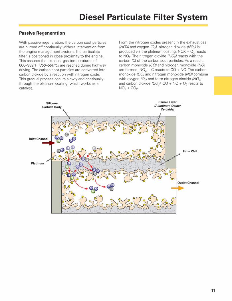
From the nitrogen oxides present in the exhaust gas (NOX) and oxygen (O2), nitrogen dioxide (NO2) is produced via the platinum coating. NOX + O2 reacts to NO2. The nitrogen dioxide (NO2) reacts with the carbon (C) of the carbon soot particles. As a result, carbon monoxide (CO) and nitrogen monoxide (NO) are formed. NO2 + C reacts to CO + NO. The carbon monoxide (CO) and nitrogen monoxide (NO) combine with oxygen (O2) and form nitrogen dioxide (NO2) and carbon dioxide (CO2). CO + NO + O2 reacts to NO2 + CO2.
Passive Regeneration
With passive regeneration, the carbon soot particles are burned off continually without intervention from the engine management system. The particulate fi lter is positioned in close proximity to the engine. This assures that exhaust gas temperatures of 660–932°F (350–500°C) are reached during highway driving. The carbon soot particles are converted into carbon dioxide by a reaction with nitrogen oxide. This gradual process occurs slowly and continually through the platinum coating, which works as a catalyst.
Silicone
Carbide Body
Inlet Channel
Filter Wall
Carrier Layer
(Aluminum Oxide/
Ceroxide)
Platinum
Outlet Channel
Diesel Particulate Filter System
12
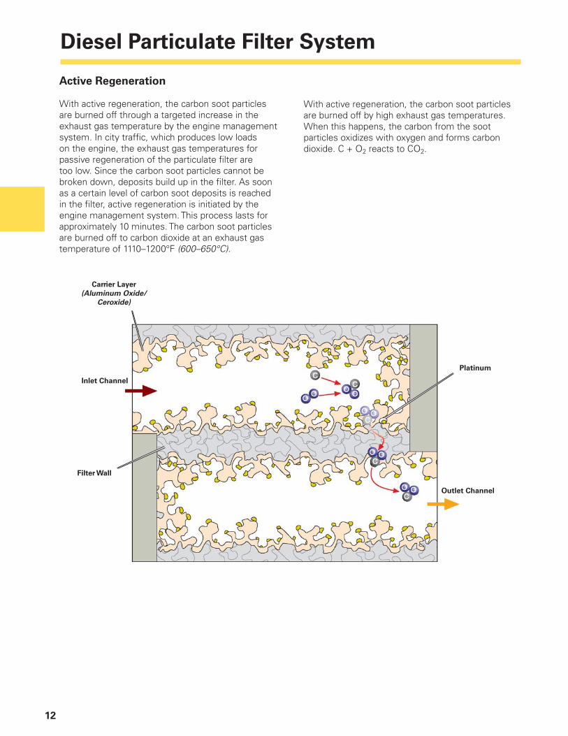
Active Regeneration
With active regeneration, the carbon soot particles are burned off through a targeted increase in the exhaust gas temperature by the engine management system. In city traffi c, which produces low loads on the engine, the exhaust gas temperatures for passive regeneration of the particulate fi lter are too low. Since the carbon soot particles cannot be broken down, deposits build up in the fi lter. As soon as a certain level of carbon soot deposits is reached in the fi lter, active regeneration is initiated by the engine management system. This process lasts for approximately 10 minutes. The carbon soot particles are burned off to carbon dioxide at an exhaust gas temperature of 1110–1200°F (600–650°C).
With active regeneration, the carbon soot particles are burned off by high exhaust gas temperatures. When this happens, the carbon from the soot particles oxidizes with oxygen and forms carbon dioxide. C + O2 reacts to CO2.
Inlet Channel
Outlet Channel
Platinum
Carrier Layer
(Aluminum Oxide/
Ceroxide)
Filter Wall

Diesel Particulate Filter System
13
Function of Active Regeneration
The carbon soot particles are retained in the inlet channels. The engine control module can detect the level of carbon soot in the particulate fi lter by evaluating the signals from the mass air fl ow sensors, the temperature senders before and after the particulate fi lter, and the exhaust pressure sensors.
When the carbon soot level reaches a predetermined limit, the engine management system initiates active regeneration.
Mass Air Flow
Sensor G70
Pre-Particle
Filter Temp
Sensor G506
Post-Particle
Filter Temp
Sensor G527
Signals to ECM
Exhaust Pressure
Sensor 1 G450
Particulate Filter Empty = low resistance to exhaust fl ow
Mass Air Flow
Sensor G70
Post-Particle
Filter Temp
Sensor G527
Signals to ECM
Pre-Particle
Filter Temp
Sensor G506
Exhaust Pressure
Sensor 1 G450
Particulate Filter Full = high resistance to exhaust gas fl ow

Diesel Particulate Filter System
14
From the fl ow resistance of the particulate fi lter, the engine control module can detect the level of carbon soot deposit in the fi lter. A high fl ow resistance indicates that the fi lter is in danger of becoming blocked. The engine control module initiates an active regeneration process. To do this:
– Exhaust gas recirculation is switched off to raise the combustion temperature
– An extended injection period is initiated after a period of main injection with reduced quantity at 35° crankshaft angle after TDC, in order to increase the exhaust gas temperature
– The supply of intake air is regulated by an electric throttle valve
– The charge air pressure is adapted so that the torque during regeneration does not change noticeably by the driver
These measures lead to a targeted, brief increase in the exhaust gas temperature to approximately 1150°F – 1200°F (600°C – 650°C). In this temperature range, the collective carbon soot oxidizes to carbon dioxide. After this active regeneration period, the particulate fi lter is ready for operation again and can begin fi ltering carbon soot out of the exhaust gas.
Engine Management During Initiation of Active Regeneration

Diesel Particulate Filter System
15
The diesel particulate fi lter warning lamp can be found in the instrument cluster. It lights up if the diesel particulate fi lter is subjected to too many short driving cycles, thus preventing regeneration.
Task
If the vehicle is driven frequently over short distances, regeneration of the diesel particulate fi lter can be impaired because the exhaust gas temperature does not reach the necessary level.
Since regeneration cannot take place, there is a risk of the fi lter becoming damaged or blocked by carbon soot deposits. In order to avoid this, the diesel particulate fi lter warning lamp lights up in the instrument cluster if the carbon soot level reaches a defi ned threshold.
With this signal, the driver is prompted to drive at more than 40 mph (60 km/h) at a constant rate for a period of about 15 minutes. The fi lter can be cleaned most effectively if the vehicle is driven in 4th or 5th gear in an engine speed range of approximately 2000 rpm. The warning lamp must go out after this procedure.
If the diesel particulate fi lter warning lamp does not go out after this procedure, the pre-glow period warning lamp will light up and a message will be displayed in the instrument cluster saying to inform the driver that the vehicle must be driven to the next dealership for service.
Diesel Particulate Filter Warning Lamp V231
ABSplus and ESP
16
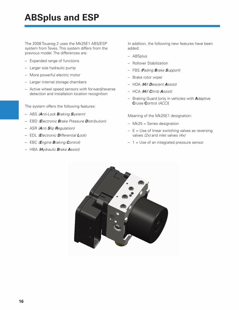
The 2008 Touareg 2 uses the Mk25E1 ABS/ESP system from Teves. This system differs from the previous model. The differences are:
– Expanded range of functions
– Larger size hydraulic pump
– More powerful electric motor
– Larger internal storage chambers
– Active wheel speed sensors with forward/reverse detection and installation location recognition
The system offers the following features:
– ABS (Anti-Lock Braking System)
– EBD (Electronic Brake Pressure Distribution)
– ASR (Anti Slip Regulation)
– EDL (Electronic Differential Lock)
– EBC (Engine Braking Control)
– HBA (Hydraulic Brake Assist)
In addition, the following new features have been added:
– ABSplus
– Rollover Stabilization
– FBS (Fading Brake Support)
– Brake rotor wiper
– HDA (Hill Descent Assist)
– HCA (Hill Climb Assist)
– Braking Guard [only in vehicles with Adaptive Cruise Control (ACC)]
Meaning of the Mk25E1 designation:
– Mk25 = Series designation
– E = Use of linear switching valves as reversing valves (2x) and inlet valves (4x)
– 1 = Use of an integrated pressure sensor
ABSplus and ESP
17
New Functions
ABS Plus
Vehicles traveling off-road can become unstable during hard braking on gritty or sandy road beds, which will effect handling and necessary braking distance. This is where ABSplus is most effective. Thanks to innovative slip control, the Touareg 2 pushes a portion of the road bed material under the temporarily locked wheels. A wedge in front of the wheel is formed, shortening braking distance without sacrifi cing steering control.
Function
With the new system, it is possible to automatically activate an off-road ABS function in either low-gear (off-road gear reduction) or high-gear (faster on-road driving). In order to shorten the braking distance on loose road beds, the ABS must recognize the road composition and automatically select the optimal control strategy based on the ESP sensor system.
Loose road beds have a friction value ranging from µ = 0.4 to µ = 0.65. On these loose beds, the maximum delay is achieved for a 100% brake slippage (blocked wheels). However, the vehicle is unstable in this condition and can no longer be steered.
This is where ABSplus takes over. ABSplus not only allows slippage, but also repeatedly allows phases with limited slippage as well. This ensures an optimum balance between distance and braking stability.
Roll-Over Stabilization
If the vehicle is in danger of rolling-over, it is automatically stabilized by reducing lateral acceleration. This is done by corrective braking at the front axle. In addition, engine torque is reduced (starting at about 0.6 g of lateral acceleration).
The ESP warning lamp fl ashes during the corrective braking action. The brake pressure build-up is achieved by activating the active brake booster and through active pressure build-up by the ESP. The active brake booster generates a rapid build-up of pressure on the vacuum side of the ESP return fl ow pump. This results in a very rapid increase in brake pressure through the ESP.
ABSplus and ESP
18
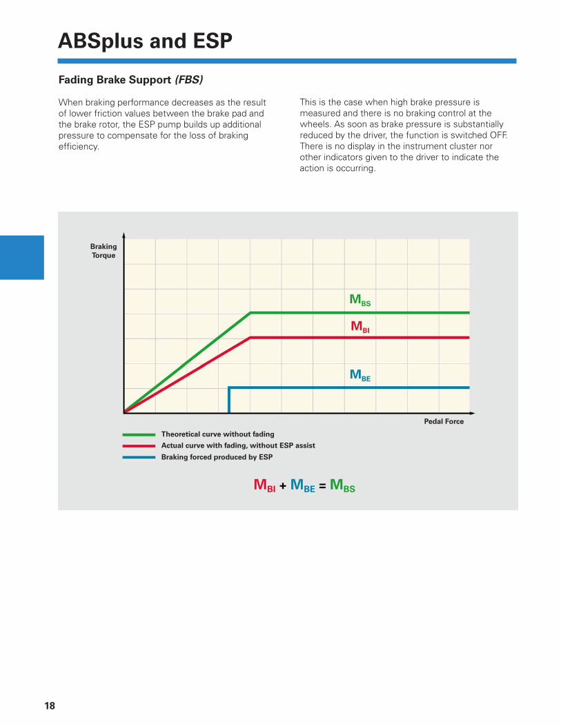
Fading Brake Support (FBS)
When braking performance decreases as the result of lower friction values between the brake pad and the brake rotor, the ESP pump builds up additional pressure to compensate for the loss of braking effi ciency.
This is the case when high brake pressure is measured and there is no braking control at the wheels. As soon as brake pressure is substantially reduced by the driver, the function is switched OFF. There is no display in the instrument cluster nor other indicators given to the driver to indicate the action is occurring.
Theoretical curve without fading
Braking
Torque
Actual curve with fading, without ESP assist
Braking forced produced by ESP
Pedal Force
ABSplus and ESP
19
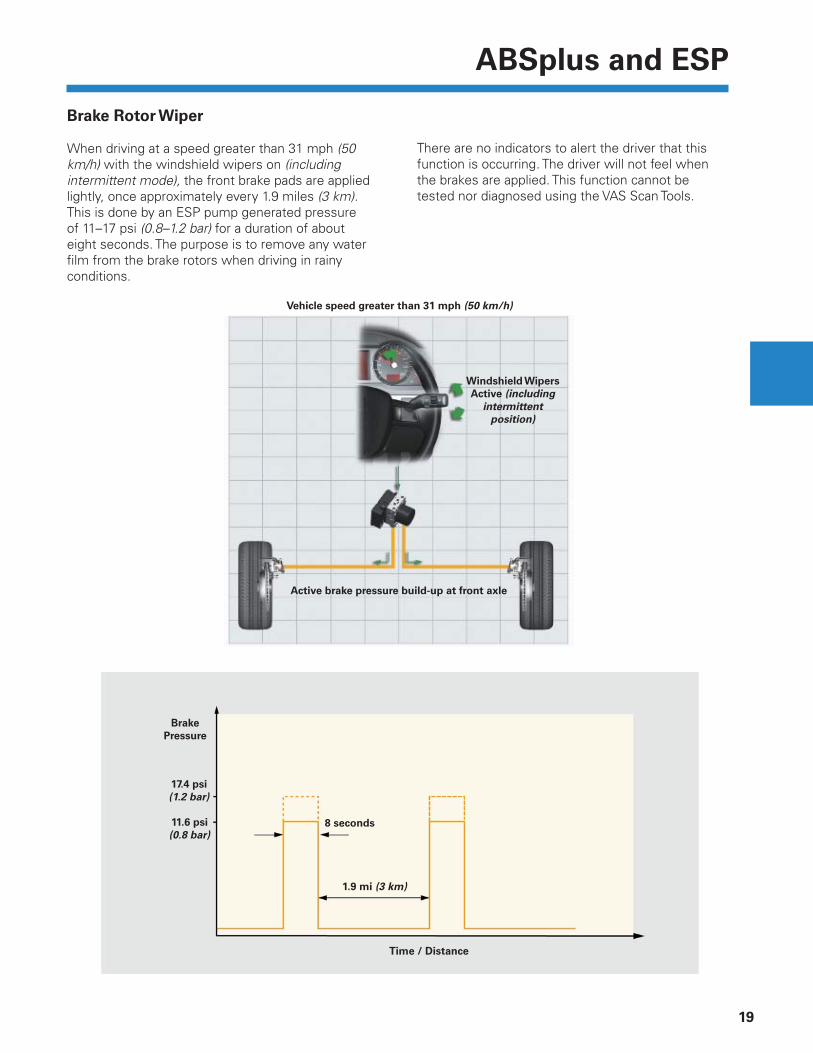
Brake Rotor Wiper
When driving at a speed greater than 31 mph (50 km/h) with the windshield wipers on (including intermittent mode), the front brake pads are applied lightly, once approximately every 1.9 miles (3 km). This is done by an ESP pump generated pressure of 11–17 psi (0.8–1.2 bar) for a duration of about eight seconds. The purpose is to remove any water fi lm from the brake rotors when driving in rainy conditions.
Windshield Wipers
Active (including
intermittent
position)
Vehicle speed greater than 31 mph (50 km/h)
Active brake pressure build-up at front axle
8 seconds
17.4 psi
(1.2 bar)
Time / Distance
Brake
Pressure
11.6 psi
(0.8 bar)
1.9 mi (3 km)
There are no indicators to alert the driver that this function is occurring. The driver will not feel when the brakes are applied. This function cannot be tested nor diagnosed using the VAS Scan Tools.
ABSplus and ESP
20
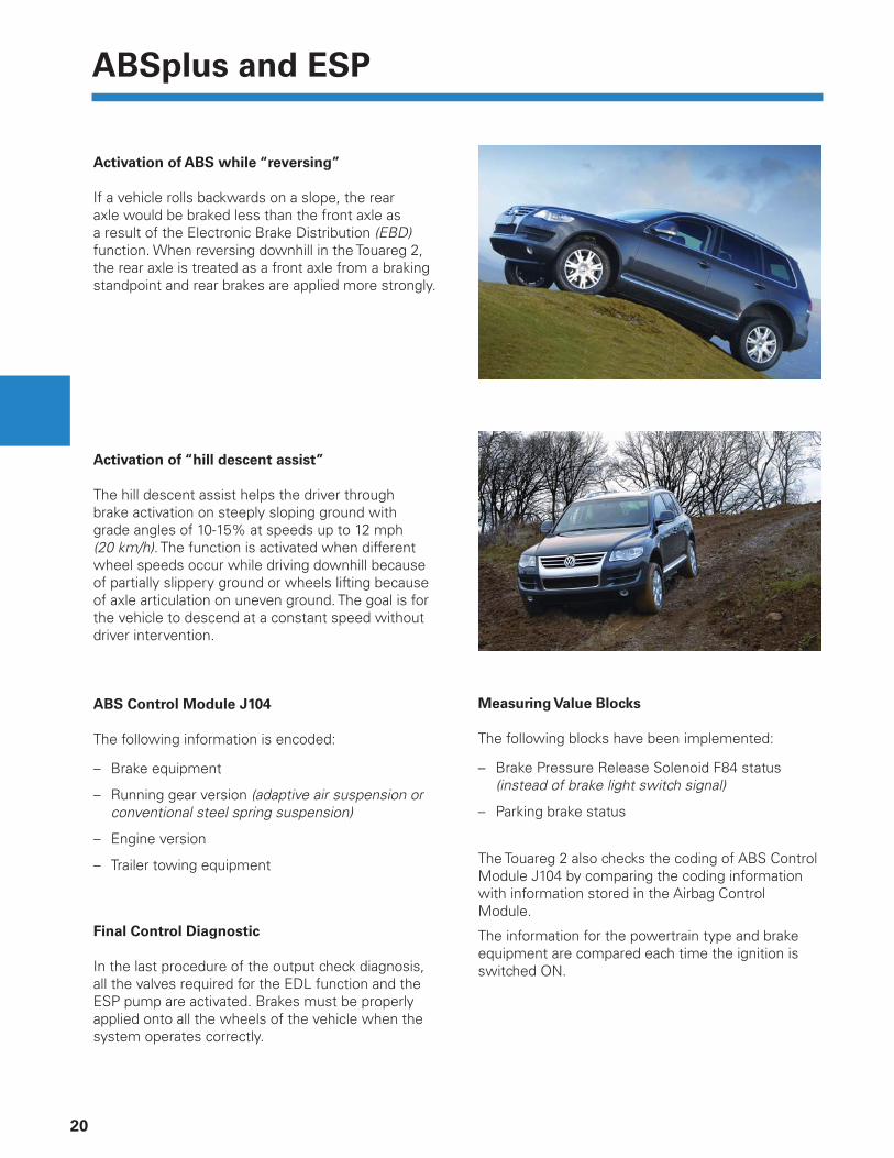
Activation of ABS while “reversing”
If a vehicle rolls backwards on a slope, the rear axle would be braked less than the front axle as a result of the Electronic Brake Distribution (EBD) function. When reversing downhill in the Touareg 2, the rear axle is treated as a front axle from a braking standpoint and rear brakes are applied more strongly.
Activation of “hill descent assist”
The hill descent assist helps the driver through brake activation on steeply sloping ground with grade angles of 10-15% at speeds up to 12 mph (20 km/h). The function is activated when different wheel speeds occur while driving downhill because of partially slippery ground or wheels lifting because of axle articulation on uneven ground. The goal is for the vehicle to descend at a constant speed without driver intervention.
ABS Control Module J104
The following information is encoded:
– Brake equipment
– Running gear version (adaptive air suspension or conventional steel spring suspension)
– Engine version
– Trailer towing equipment
Final Control Diagnostic
In the last procedure of the output check diagnosis, all the valves required for the EDL function and the ESP pump are activated. Brakes must be properly applied onto all the wheels of the vehicle when the system operates correctly.
Measuring Value Blocks
The following blocks have been implemented:
– Brake Pressure Release Solenoid F84 status (instead of brake light switch signal)
– Parking brake status
The Touareg 2 also checks the coding of ABS Control Module J104 by comparing the coding information with information stored in the Airbag Control Module.
The information for the powertrain type and brake equipment are compared each time the ignition is switched ON.
Tire Pressure Monitoring System
21
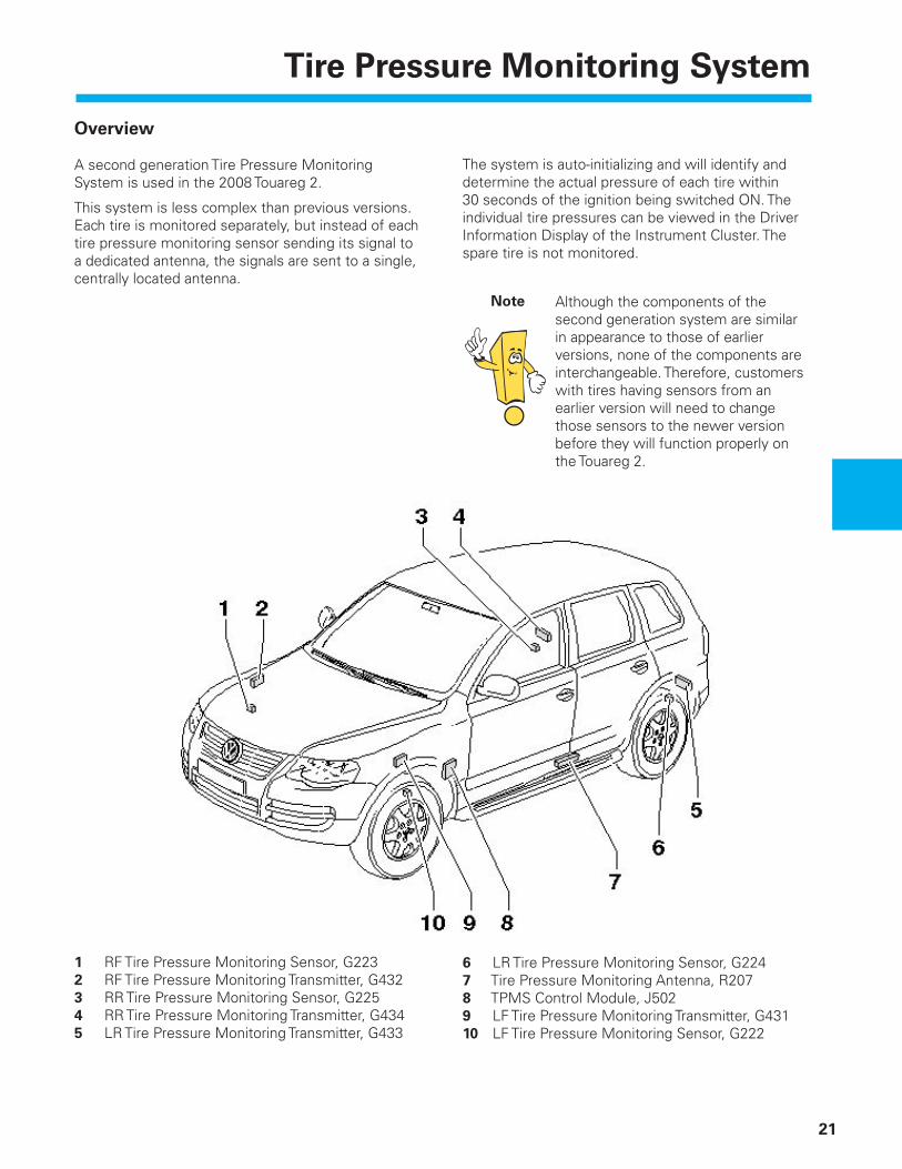
Overview
A second generation Tire Pressure Monitoring System is used in the 2008 Touareg 2.
This system is less complex than previous versions. Each tire is monitored separately, but instead of each tire pressure monitoring sensor sending its signal to a dedicated antenna, the signals are sent to a single, centrally located antenna.
The system is auto-initializing and will identify and determine the actual pressure of each tire within 30 seconds of the ignition being switched ON. The individual tire pressures can be viewed in the Driver Information Display of the Instrument Cluster. The spare tire is not monitored.
Although the components of the second generation system are similar in appearance to those of earlier versions, none of the components are interchangeable. Therefore, customers with tires having sensors from an earlier version will need to change those sensors to the newer version before they will function properly on the Touareg 2.
Note
1 RF Tire Pressure Monitoring Sensor, G2232 RF Tire Pressure Monitoring Transmitter, G4323 RR Tire Pressure Monitoring Sensor, G2254 RR Tire Pressure Monitoring Transmitter, G4345 LR Tire Pressure Monitoring Transmitter, G433
6 LR Tire Pressure Monitoring Sensor, G2247 Tire Pressure Monitoring Antenna, R2078 TPMS Control Module, J5029 LF Tire Pressure Monitoring Transmitter, G43110 LF Tire Pressure Monitoring Sensor, G222
Tire Pressure Monitoring System
22
Function
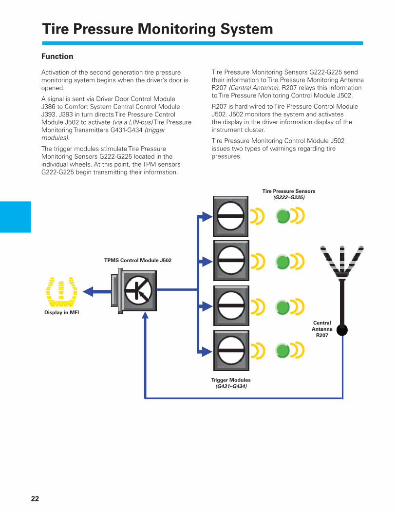
Activation of the second generation tire pressure monitoring system begins when the driver’s door is opened.
A signal is sent via Driver Door Control Module J386 to Comfort System Central Control Module J393. J393 in turn directs Tire Pressure Control Module J502 to activate (via a LIN-bus) Tire Pressure Monitoring Transmitters G431-G434 (trigger modules).
The trigger modules stimulate Tire Pressure Monitoring Sensors G222-G225 located in the individual wheels. At this point, the TPM sensors G222-G225 begin transmitting their information.
Tire Pressure Monitoring Sensors G222-G225 send their information to Tire Pressure Monitoring Antenna R207 (Central Antenna). R207 relays this information to Tire Pressure Monitoring Control Module J502.
R207 is hard-wired to Tire Pressure Control Module J502. J502 monitors the system and activates the display in the driver information display of the instrument cluster.
Tire Pressure Monitoring Control Module J502 issues two types of warnings regarding tire pressures.
Central
Antenna
R207
Tire Pressure Sensors
(G222–G225)
TPMS Control Module J502
Display in MFI
Trigger Modules
(G431–G434)

Tire Pressure Monitoring System
23
Networking
The tire pressure monitoring system participates on the Convenience CAN-bus.
Legend
E415 Access/Start Authorization Switch
G17 Outside Air Temperature SensorG44 RR ABS Wheel Speed SensorG45 RF ABS Wheel Speed SensorG46 LR ABS Wheel Speed Sensor G47 LF ABS Wheel Speed Sensor
G222 LF Tire Pressure Monitoring SensorG223 RF Tire Pressure Monitoring SensorG224 LR Tire Pressure Monitoring SensorG225 RR Tire Pressure Monitoring Sensor
G431 LF Tire Pressure Monitoring TransmitterG432 RF Tire Pressure Monitoring TransmitterG433 LR Tire Pressure Monitoring TransmitterG434 RR Tire Pressure Monitoring Transmitter
J104 ABS Control Module J255 Climatronic Control ModuleJ285 Instrument Cluster Control ModuleJ393 Comfort System Central Control ModuleJ502 TPMS Control ModuleJ533 Data Bus On Board Diagnostic Interface
J255
G222
J502 E415
LIN-bus
Convenience
CAN-bus
J393
J104J285 / J533
G223
G224
G225
G431
G432
G433
G434
G44
G45
G46
G47
G17
R207
Drivetrain
CAN-bus

Lane Change Assistant
24
Starting in 2009, the Touareg will have an available Lane Change Assistant system. The Lane Change Assistant system (LCA) uses radar sensors to monitor “blind spots”— areas to the rear and sides of the vehicle to help the driver during a lane change. The driver’s and the passenger’s sides are both monitored, each with its own separate radar module.
If the system detects a critical situation which could result in an accident during a lane change, it both informs and warns the driver. The driver is informed by the activation of the warning lights in the appropriate exterior rear-view mirror, and is warned by the warning lights fl ashing brightly. Though there is a warning, no active intervention is taken by the vehicle.
Lane Change Assistant
25
Area Monitored by the Radar Sensor
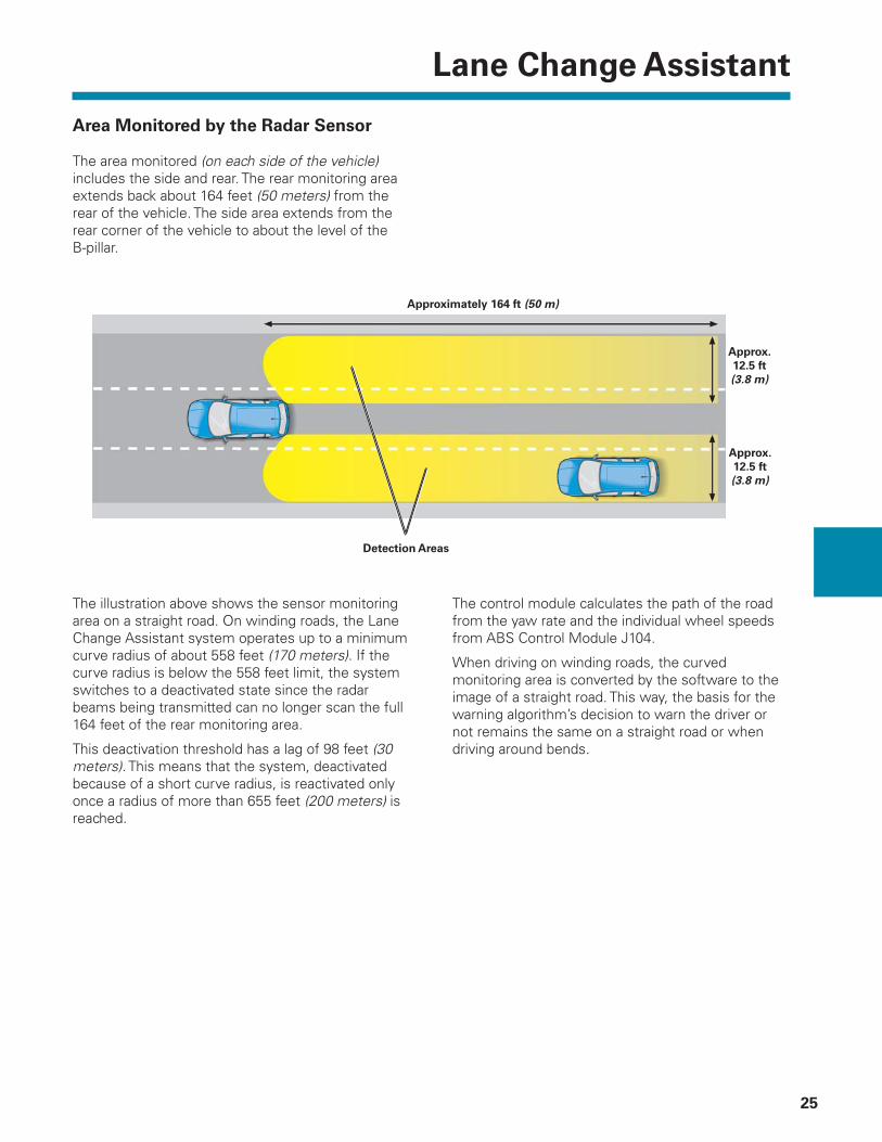
The area monitored (on each side of the vehicle) includes the side and rear. The rear monitoring area extends back about 164 feet (50 meters) from the rear of the vehicle. The side area extends from the rear corner of the vehicle to about the level of the B-pillar.
The control module calculates the path of the road from the yaw rate and the individual wheel speeds from ABS Control Module J104.
When driving on winding roads, the curved monitoring area is converted by the software to the image of a straight road. This way, the basis for the warning algorithm’s decision to warn the driver or not remains the same on a straight road or when driving around bends.
The illustration above shows the sensor monitoring area on a straight road. On winding roads, the Lane Change Assistant system operates up to a minimum curve radius of about 558 feet (170 meters). If the curve radius is below the 558 feet limit, the system switches to a deactivated state since the radar beams being transmitted can no longer scan the full 164 feet of the rear monitoring area.
This deactivation threshold has a lag of 98 feet (30 meters). This means that the system, deactivated because of a short curve radius, is reactivated only once a radius of more than 655 feet (200 meters) is reached.
Approx.
12.5 ft
(3.8 m)
Approximately 164 ft (50 m)
Detection Areas
Approx.
12.5 ft
(3.8 m)

Lane Change Assistant
26
Two Typical Traffi c Situations
As an example, two typical traffi c situations are described below, which can result in a warning from the lane change assistance system.
Scenario 1
The vehicle with the Lane Change Assistant (LCA) is traveling in the center lane of a three-lane freeway and is just passing the vehicle on the right. The speed differential between the car with LCA and the vehicle being passed is less than 9.3 mph (15 km/h).
As a result of the small speed differential, the passing maneuver takes some time, and the vehicle being passed disappears at some point in the “blind spot.” In this situation, the warning lamp in the right exterior mirror informs the driver that the right lane is occupied. If the driver of the LCA-vehicle now uses his right turn signal, the driver is warned by the lamp in the right exterior mirror fl ashing four times.
Scenario 2
The vehicle with the Lane Change Assistant (LCA) is traveling at medium speed in the right lane of a three-lane freeway. A vehicle approaches from the rear in the center lane at a clearly higher speed. The approaching vehicle is detected by the lane change assistance system, which activates the warning lamp in the left exterior mirror. If the left turn signal is now used, a fl ashing warning lamp warns the driver against making a lane change because of the danger of a collision.
The distance between the vehicles at which the warning lamps are activated depends on the speed differential. The greater the speed differential, the higher the distance between the two vehicles at which the driver is informed of the danger of a potential collision. However, the earliest warning can only come at a 164 feet (50 meters) distance, since this is the upper limit of the radar sensors detection range.
Lane Change Assistant
27
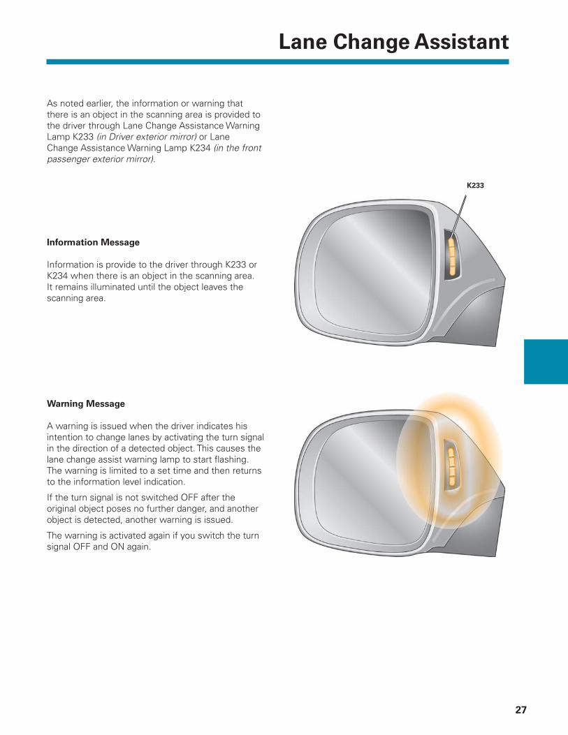
As noted earlier, the information or warning that there is an object in the scanning area is provided to the driver through Lane Change Assistance Warning Lamp K233 (in Driver exterior mirror) or Lane Change Assistance Warning Lamp K234 (in the front passenger exterior mirror).
Information Message
Information is provide to the driver through K233 or K234 when there is an object in the scanning area. It remains illuminated until the object leaves the scanning area.
Warning Message
A warning is issued when the driver indicates his intention to change lanes by activating the turn signal in the direction of a detected object. This causes the lane change assist warning lamp to start fl ashing. The warning is limited to a set time and then returns to the information level indication.
If the turn signal is not switched OFF after the original object poses no further danger, and another object is detected, another warning is issued.
The warning is activated again if you switch the turn signal OFF and ON again.
K233
Lane Change Assistant
28
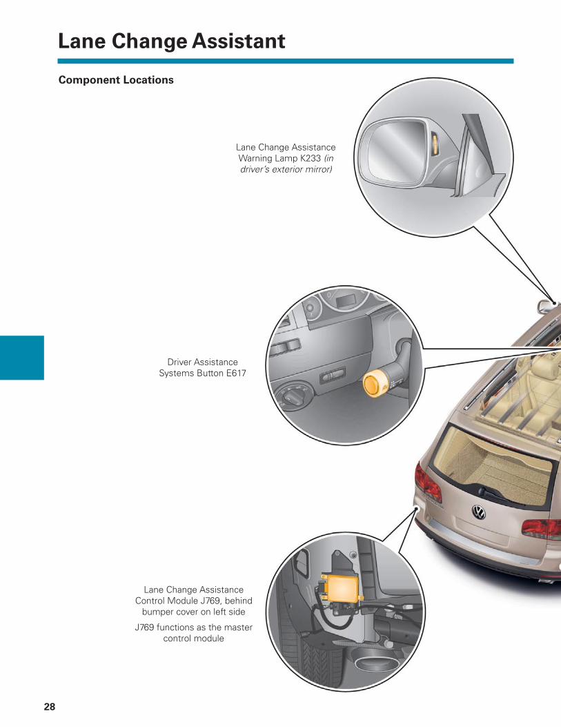
Component Locations
Lane Change Assistance Warning Lamp K233 (in driver’s exterior mirror)
Driver Assistance Systems Button E617
Lane Change Assistance Control Module J769, behind
bumper cover on left side
J769 functions as the master control module
Lane Change Assistant
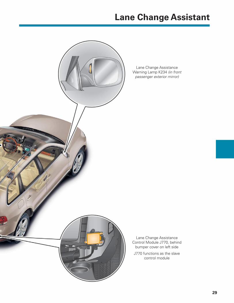
29
Lane Change Assistance Control Module J770, behind
bumper cover on left side
J770 functions as the slave control module
Lane Change Assistance Warning Lamp K234 (in front
passenger exterior mirror)

Lane Change Assistant
30
Radar Sensors and Control Modules
The lane change assistance system has two control modules, Lane Change Assistance Control Module J769 (master control module) and Lane Change Assistance Control Module 2 J770 (slave control module). The master control module forms one unit with the right side radar sensor, and the slave control module forms one unit with the left-side radar sensor. The master and slave control modules share an identical design. They are based on a printed circuit board with a digital signal processor as the central computing unit. One of its functions is to detect and track objects recognized by the radar sensors.
The antenna board with the transmitting and receiving antennas is connected to the electronics board by means of a strip connector. The transmitting antenna consists of 40 copper facets, and the 3 receiving antenna consist of 8 or 16 copper facets. A copper facet is called a “patch” in technical language.
The refl ected radiation recorded by the receiving antenna is then analyzed by the digital signal processor to identify its physical properties. This information is used to calculate the size, position and speed of the refl ecting object.
The control module upper cover is a plastic “radome”. This is a special plastic allowing optimal penetration of the radar beams without degradation.

Lane Change Assistant
31
Driver Assistance Systems Button
Driver Assistance Systems Button E617 is located at the end of the turn signal stalk.
Displays
Highline Instrument Cluster
Lane Change Assistance Indicator Lamp K232 is located in the speedometer of the instrument cluster.
System status is indicated by the color of the warning lights:
– Green — Lane change assist switched ON and active [at speeds above 37 mph (60 km/h)]
– Yellow — Lane change assist switched ON and passive [at speeds below 31 mph (50 km/h)]
Premium Instrument Cluster
Lane Change Assistance Indicator Lamp K232 is located in the MFI of the instrument cluster.
System status is indicated by the color of the warning lights:
– Green — Lane change assist switched ON and active [at speeds above 37 mph (60 km/h)]
– Yellow — Lane change assist switched ON and passive [at speeds below 31 mph (50 km/h)]

Lane Change Assistant
32
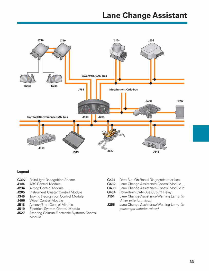
Networking of the Lane Change Assist System
Control Modules
The system has two control modules: Lane Change Assistance Control Module J769 and Lane Change Assistance Control Module 2 J770. As stated, these control modules have a master and slave relationship.
J769 is confi gured as the master control module, while J770 is the slave module. The control modules communicate with each other over a private lane change assist CAN-bus. They communicate at a transfer speed of 500 bits/sec.
CAN-bus Messages
The following CAN-bus messages are required for the operation of the Lane Change Assistant system:
– Airbag Control Module J234 (storage of warming lamp status)
– ABS Control Module J104 (provides speed and yaw rate signal)
– Instrument Cluster Control Module J285 and Data Bus On Board Diagnostic Interface J533 (provide display of activation statuses and forwarding of all CAN-bus messages)
– Electrical System Control Module J519 (provides turn signal position)
Lane Change Assistance Control Module J769 is a member of the Powertrain CAN-bus through which it receives all necessary information for its functions.
When the ignition is switched OFF, the connection between the Powertrain CAN-bus and J769 is disconnected by Powertrain CAN-Bus Cut-Off Relay J788. This is done for security reasons.
– Towing Recognition Control Module J345 (indication of whether a trailer is attached and if necessary, deactivation of the lane change assist function)
– Wiper Control Module J400 (provides the signal from Rain/Light Recognition Sensor G397)
– Access/Start Control Module J518 (provides radio remote key signal)
Lane Change Assistant
33
Legend
G397 Rain/Light Recognition SensorJ104 ABS Control ModuleJ234 Airbag Control ModuleJ285 Instrument Cluster Control ModuleJ345 Towing Recognition Control Module J400 Wiper Control ModuleJ518 Access/Start Control ModuleJ519 Electrical System Control ModuleJ527 Steering Column Electronic Systems Control Module
G431 Data Bus On Board Diagnostic InterfaceG432 Lane Change Assistance Control ModuleG433 Lane Change Assistance Control Module 2G434 Powertrain CAN-Bus Cut-Off RelayJ104 Lane Change Assistance Warning Lamp (in driver exterior mirror) J255 Lane Change Assistance Warning Lamp (in passenger exterior mirror)
K233
J769 J104
K234
J770 J234
J527J519 J345
J285
J518
Infotainment CAN-bus
J533
J788
J400 G397
Powertrain CAN-bus
Comfort/Convenience CAN-bus

Lane Change Assistant
34
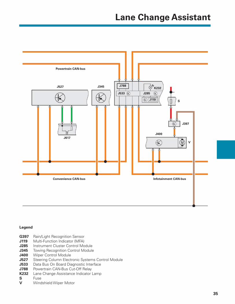
Functional Diagram
Legend
J769 Lane Change Assistance Control Module
J770 Lane Change Assistance Control Module 2
K233 Lane Change Assistance Warning Lamp (in driver exterior mirror)
K234 Lane Change Assistance Warning Lamp (in passenger exterior mirror)
S Fuse
J769
Lane Change Assist
CAN-bus
K234
Powertrain CAN-bus
J770
S
K233
Lane Change Assistant
35
Legend
G397 Rain/Light Recognition SensorJ119 Multi-Function Indicator (MFA)J285 Instrument Cluster Control ModuleJ345 Towing Recognition Control ModuleJ400 Wiper Control Module J527 Steering Column Electronic Systems Control ModuleJ533 Data Bus On Board Diagnostic InterfaceJ788 Powertrain CAN-Bus Cut-Off RelayK232 Lane Change Assistance Indicator LampS FuseV Windshield Wiper Motor
Powertrain CAN-bus
J345
J533
S
J788J527
J285
J397
K232
J617
J400
V
Convenience CAN-bus Infotainment CAN-bus
J119
Lane Change Assistant
36
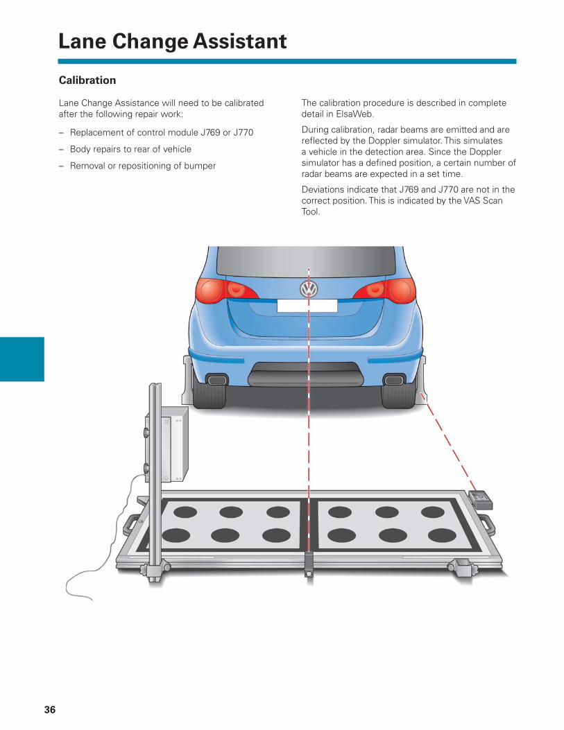
Calibration
Lane Change Assistance will need to be calibrated after the following repair work:
– Replacement of control module J769 or J770
– Body repairs to rear of vehicle
– Removal or repositioning of bumper
The calibration procedure is described in complete detail in ElsaWeb.
During calibration, radar beams are emitted and are refl ected by the Doppler simulator. This simulates a vehicle in the detection area. Since the Doppler simulator has a defi ned position, a certain number of radar beams are expected in a set time.
Deviations indicate that J769 and J770 are not in the correct position. This is indicated by the VAS Scan Tool.
Lane Change Assistant
37
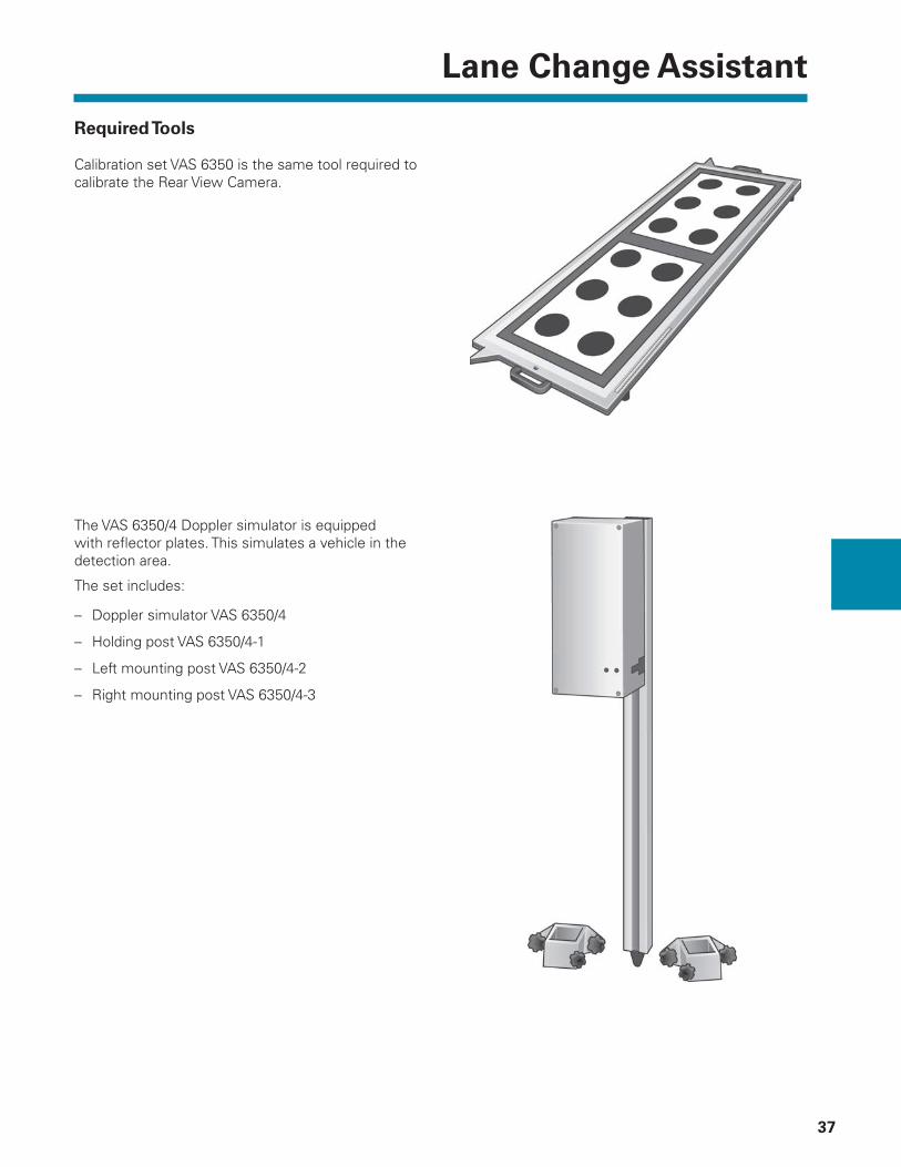
Required Tools
Calibration set VAS 6350 is the same tool required to calibrate the Rear View Camera.
The VAS 6350/4 Doppler simulator is equipped with refl ector plates. This simulates a vehicle in the detection area.
The set includes:
– Doppler simulator VAS 6350/4
– Holding post VAS 6350/4-1
– Left mounting post VAS 6350/4-2
– Right mounting post VAS 6350/4-3

Back-Up Rear View Camera
38
An optional Review Camera is available on the Touareg 2. It is included when the vehicle is equipped with the Technology Package.
The Rear View Camera provides the driver with improved vision by scanning the rear area of the vehicle and displaying it on the Radio/Navigation screen. This simplifi es the tasks of backing-up on a street or parking.
The Rear View Camera is switched ON automatically any time Reverse gear is selected while the ignition is in the ON position. The image from the Rear View Camera will switch OFF automatically when driving forward for 20 seconds or when the vehicle speed reaches 10 mph (15 km/h).
The camera is located on the Liftgate near the license plate lights. The image displayed on the screen shows the area behind the vehicle and is similar to the view through the interior rear view mirror.
Orientation lines are projected onto the image by the Rear View Camera Control Module and help the driver when maneuvering. The orientation lines are superimposed on vehicles or objects displayed on the screen when the vehicle is closer that the distances shown.
Two display modes are available.
Display Mode 1 is used for assistance when parking in a garage or backing into a parking space.
Display Mode 2 is used for assistance when parking at the edge of a road.
Changing between Modes is done through the Settings menu of the Navigation/Radio controls.
Rear View Camera
Back-Up Rear View Camera
39
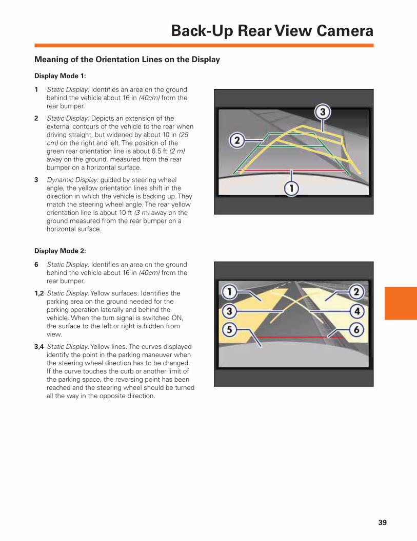
Display Mode 1:
1 Static Display: Identifi es an area on the ground behind the vehicle about 16 in (40cm) from the rear bumper.
2 Static Display: Depicts an extension of the external contours of the vehicle to the rear when driving straight, but widened by about 10 in (25 cm) on the right and left. The position of the green rear orientation line is about 6.5 ft (2 m) away on the ground, measured from the rear bumper on a horizontal surface.
3 Dynamic Display: guided by steering wheel angle, the yellow orientation lines shift in the direction in which the vehicle is backing up. They match the steering wheel angle. The rear yellow orientation line is about 10 ft (3 m) away on the ground measured from the rear bumper on a horizontal surface.
Display Mode 2:
6 Static Display: Identifi es an area on the ground behind the vehicle about 16 in (40cm) from the rear bumper.
1,2 Static Display: Yellow surfaces. Identifi es the parking area on the ground needed for the parking operation laterally and behind the vehicle. When the turn signal is switched ON, the surface to the left or right is hidden from view.
3,4 Static Display: Yellow lines. The curves displayed identify the point in the parking maneuver when the steering wheel direction has to be changed. If the curve touches the curb or another limit of the parking space, the reversing point has been reached and the steering wheel should be turned all the way in the opposite direction.
Meaning of the Orientation Lines on the Display
Back-Up Rear View Camera
40
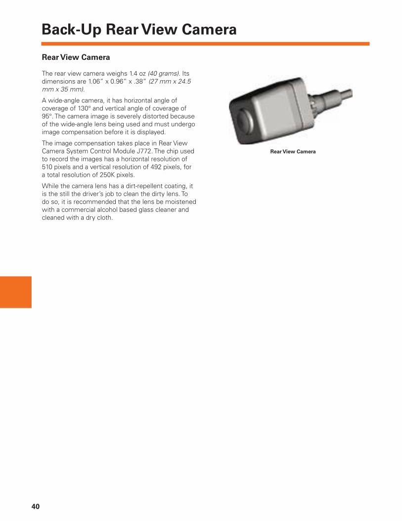
Rear View Camera
The rear view camera weighs 1.4 oz (40 grams). Its dimensions are 1.06” x 0.96” x .38” (27 mm x 24.5 mm x 35 mm).
A wide-angle camera, it has horizontal angle of coverage of 130° and vertical angle of coverage of 95°. The camera image is severely distorted because of the wide-angle lens being used and must undergo image compensation before it is displayed.
The image compensation takes place in Rear View Camera System Control Module J772. The chip used to record the images has a horizontal resolution of 510 pixels and a vertical resolution of 492 pixels, for a total resolution of 250K pixels.
While the camera lens has a dirt-repellent coating, it is the still the driver’s job to clean the dirty lens. To do so, it is recommended that the lens be moistened with a commercial alcohol based glass cleaner and cleaned with a dry cloth.
Rear View Camera
Back-Up Rear View Camera
41
Rear View Camera System Control Module J772
J772 is part of the Comfort System CAN-bus. J772 has the following tasks:
– Provide the supply voltage to the Rear View Camera
– Compensate the wide-angle camera image
– Insert the static and dynamic assistance lines into the camera image
– Provide a video input for the camera signal
– Provide a video input for the TV tuner
– Switch over to the desired video signal with an integral video switch
– Provide a video output of the completed video signal
– Perform the control module self-diagnosis
– Perform the diagnosis of incoming camera signals
– Perform the system calibration with a VAS Scan Tool and calibration board
Though not available in North America, a TV tuner is offered as optional equipment in other markets. If no TV tuner is installed in the vehicle, the second video input on the rear view camera control module remains unused.
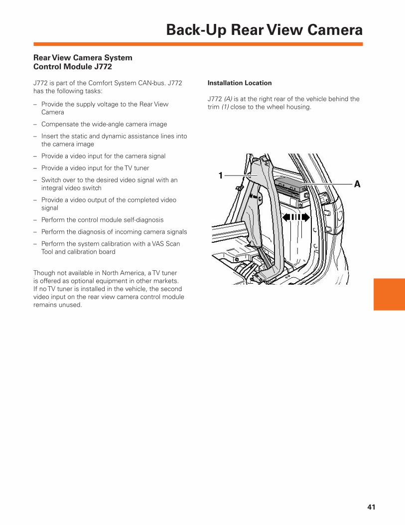
Installation Location
J772 (A) is at the right rear of the vehicle behind the trim (1) close to the wheel housing.

Back-Up Rear View Camera
42
Calibration
The rear view camera will need to be calibrated after the following repair work:
– Replacement of Rear View Camera Control Module J772
– Replacement of Rear View Camera R189
– Body repairs to rear of vehicle or liftgate
The calibration procedure is described in complete detail in the repair manual. It requires the use of calibration tool VAS 6350.

Back-Up Rear View Camera
43
Functional Wiring Diagram
The rear view camera and its control module are connected to each other by 4 wires. There is a wire for the camera power supply, a matching ground wire, a shielded wire for the video signal, as well as a video signal shield that is connected to the ground. The camera is switched ON and OFF through the supply voltage. The supply voltage for the camera is 6.5 Volts and is generated in J772 by means of a switched mode power supply.
The supply voltage for the camera is switched OFF above a speed of about 15 mph (25 km/h).
Radio/Navigation Display Control Module J503 has only one video input although there may be two video signal sources in the vehicle: TV Tuner R78 (not available in North America) and Rear View Camera R189.
For this reason, control module J772 has two video inputs and a video switch which feeds the image from the TV tuner or the image from the rear view camera as its video output. The video output of J772 is connected to the video input of J503.
The normal position for the video switch in J772 is shown in the illustration above: the video signal from the TV tuner is applied to the video output. The video splitter only switches to the rear view camera when the rear view image is needed. The image from the rear view camera must fi rst be processed in J772 before it reaches J503 over the video switch and the video output.
30
Comfort CAN — High
Rear View
Camera R189
31
Rear View
Camera System
Control Module
J772
Shielded Wire
Image
Processor
Comfort CAN — Low
TV Tuner R78Radio/Navigation
Display Control
Module J503
Back-Up Rear View Camera
44
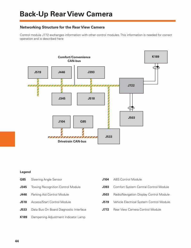
Networking Structure for the Rear View Camera
Control module J772 exchanges information with other control modules. This information is needed for correct operation and is described here:
Legend
G85 Steering Angle Sensor
J345 Towing Recognition Control Module
J446 Parking Aid Control Module
J518 Access/Start Control Module
J533 Data Bus On Board Diagnostic Interface
K189 Dampening Adjustment Indicator Lamp
J104 ABS Control Module
J393 Comfort System Central Control Module
J503 Radio/Navigation Display Control Module
J519 Vehicle Electrical System Control Module
J772 Rear View Camera Control Module
J519 J393
K189
J104
J722
J446
J503
J345
G85
J533
J518
Comfort/Convenience
CAN-bus
Drivetrain CAN-bus

Back-Up Rear View Camera
45
Steering Angle Sensor G85
Provides the current steering angle which is needed to calculate the dynamic assist lines in the camera image.
Parking Aid Control Module J446
Informs whether the parking aid is currently active based on the button activation or based on engaged reverse gear, and whether the Parking Aid Control Module is defective.
Towing Recognition Control Module J345
Communicates to the Rear View Camera System whether a trailer is currently attached to the vehicle or not. If there is a trailer on the vehicle, the assist lines and the assist fi eld are deactivated.
Comfort System Central Control Module J393
Transmits the information whether the rear hatch is closed or open. If the rear hatch is open, the assist lines and the assist fi eld are deactivated. Access/Start Control Module J518 transmits current status of terminal 15 to the Rear View Camera.
Radio/Navigation Display Control Module J503
Shows the camera image on its display. In addition, it allows to defi ne system settings for the Rear View Camera.
Vehicle Electrical System Control Module J519
Informs whether the backup light is being activated. On vehicles without Parking Aid Control Module, this verifi es that reverse gear is currently engaged, and that the camera image must be displayed.
ABS Control Module J104
The vehicle speed measured by J104 is needed to determine the conditions for switching the Rear View Camera ON and OFF.
Data Bus On Board Diagnostic Interface J533
Places required CAN messages from other bus systems on the Comfort System CAN-bus, and transmits freeze frame information in the event of a fault memory entry in Control Module J722.
The following control modules are optional and not available for all markets. Therefore, they may not installed in every Touareg 2:
– Parking Aid Control Module J446
– Towing Recognition Control Module J345
– TV tuner R 78

Power Liftgate
46
The optional power liftgate of the Touareg 2 is an electro-hydraulic system similar to the one used on the Phaeton. An electrically driven rotary piston hydraulic pump supplies pressure to an actuating cylinder mounted near the left hinge. The liftgate is also supported at each hinge by gas-fi lled struts.
The hydraulic pump’s bi-directional motor operates in one of two directions depending on whether the liftgate is being opened or closed.
This pump is located under the left side of the rear seat in a special sound deadening capsule. The liftgate also has an electrically operating closing latch. The closing latch draws the liftgate to fully closed and locked position.
In the event of electric or hydraulic failure, the liftgate can be opened manually.
The liftgate can be operated in any one of four manners:
1 By pressing the switch located in the driver’s door panel
2 By pressing the trunk button on the radio remote key
3 By pressing the button under the VW emblem on the liftgate
4 By pressing the button on the inside of the liftgate (used for closing)

Power Liftgate
47
Power Liftgate Opening Adaptation
The power liftgate opening height can be set by the customer.
The customer fi rst opens the liftgate to the desired opening, electrically or manually.
Once at the desired opening, the customer pushes and holds the liftgate operating switch for approximately fi ve seconds. Confi rmation of the adaptation is acknowledged by one fl ashing of the hazard warning lights.
The opening position is NOT saved if the button is pushed for longer than 60 seconds.
Anti-Trap Function
If the opening or closing of the power liftgate is interrupted by an obstacle, the operation will stop and the direction of travel reversed approximately 5° to 10°.
This provides two safety functions. It helps ensure that nothing is trapped by the operation of the power liftgate. It also protects the liftgate from being damaged by a garage door, a low parking garage roof, or other objects.
“Play Protection”
A “play protection” feature is integrated into the power liftgate control module software. It provides protection to liftgate components (particularly the hydraulic unit), due to any overheating from repeated use of the liftgate.
As soon as the hydraulic unit’s electric motor receives current and is running, a counter in the control module is incremented by the value 1 every second.
As soon as the hydraulic unit’s electric motor no longer receives current, the counter is decremented by 1 every three seconds.
If the counter reaches a value of over 120 due to excessively frequent, successive actuation of the automatic tailgate, the play protection system is activated:
– The tailgate opening or closing process last begun is completed
– One further closing process is permitted by the play protection system
– A further opening process is only permitted by the system following a break, in which the counter is decremented to a value below 120
In the event of continuous actuation, approximately 10 successive opening and closing processes are possible before the control module activates the “play protection” system.

Power Liftgate
48
Hydraulic Components
1 Electro-hydraulic pump
2 Pump insulating capsule
3 Hydraulic lines
4 Adhesive foam strip
5 Cable retaining bracket
6 Ball stud on rear hinge
7 Hydraulic cylinder
8 Protective grommet
9 Retaining bolts
10 Bracket
11 Hydraulic connections
12 Pump insulating capsule

Power Liftgate
49
Temperature Dependent Hydraulic Pressure
Regulation
Hydraulic system pressure is regulated depending on temperature, to ensure safe and reliable opening and closing functions.
To do this, the temperature of the hydraulic system components and the gas-fi lled struts are determined and the pressure in the hydraulic system is regulated accordingly.
To determine optimal pressure, the following parameters are monitored:
– The value from Intake Air Temperature Sensor G17
– The temperature of the tailgate control module
– The vehicle inclination
– The door status
– Time factors (for example, stationary time, play protection value)
The power liftgate control module then sets the correct pressure values for operation.
The liftgate system will only recognize a hitched trailer if there is an electrical connection to the towing attachment.
On vehicles equipped with factory installed trailer hitches, as soon as the electrical connection is established at the trailer connector, the liftgate can no longer be opened or closed electro-hydraulically.
On vehicles with non-factory installed trailer hitches, without an electrical connection to the towing attachment, the liftgate is not disabled. Damage could occur during liftgate operation.
Note
Power Liftgate
50
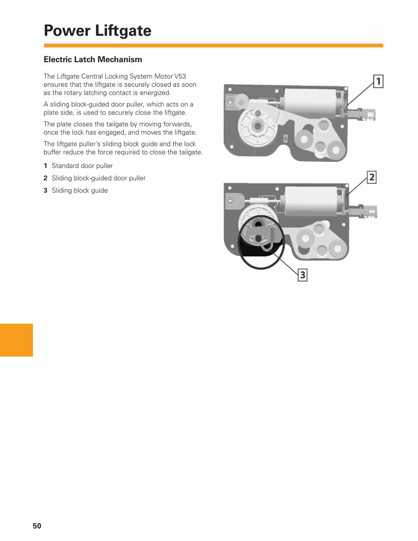
Electric Latch Mechanism
The Liftgate Central Locking System Motor V53 ensures that the liftgate is securely closed as soon as the rotary latching contact is energized.
A sliding block-guided door puller, which acts on a plate side, is used to securely close the liftgate.
The plate closes the tailgate by moving forwards, once the lock has engaged, and moves the liftgate.
The liftgate puller’s sliding block guide and the lock buffer reduce the force required to close the tailgate.
1 Standard door puller
2 Sliding block-guided door puller
3 Sliding block guide
Power Liftgate
51
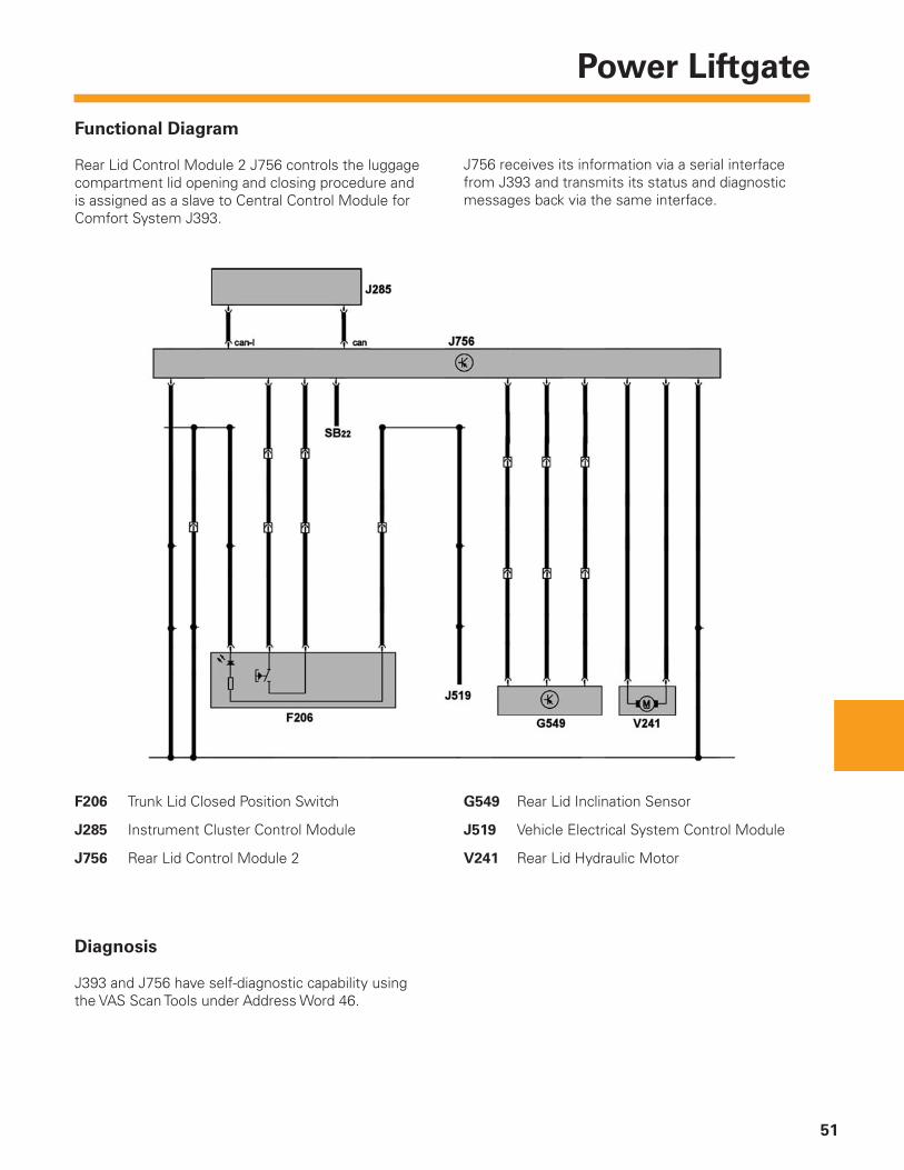
F206 Trunk Lid Closed Position Switch
J285 Instrument Cluster Control Module
J756 Rear Lid Control Module 2
G549 Rear Lid Inclination Sensor
J519 Vehicle Electrical System Control Module
V241 Rear Lid Hydraulic Motor
Functional Diagram
Rear Lid Control Module 2 J756 controls the luggage compartment lid opening and closing procedure and is assigned as a slave to Central Control Module for Comfort System J393.
J756 receives its information via a serial interface from J393 and transmits its status and diagnostic messages back via the same interface.
Diagnosis
J393 and J756 have self-diagnostic capability using the VAS Scan Tools under Address Word 46.

Notes
52
Knowledge Assessment
53
An on-line Knowledge Assessment (exam) is available for this Self-Study Program.
The Knowledge Assessment may or may not be required for Certifi cation.
You can fi nd this Knowledge Assessment at:
www.vwwebsource.com
For Assistance, please call:
Volkswagen Academy
Certifi cation Program Headquarters
1–877–491–4838
(8:00 a.m. to 8:00 p.m. EST)
Or, E-Mail:
893803
Volkswagen Group of America, Inc.2200 Ferdinand Porsche DriveHerndon, VA 20171Printed in the U.S.A.October 2008