
Seite 1 - Sumitomo
50
TECHNICAL INFORMATION N-P Technical Guidance | Spare Parts | Index 20|21
Transcript of Seite 1 - Sumitomo
TECHNICAL INFORMATION
N-P
Technical Guidance | Spare Parts | Index
20|21

N1–N24N
N1
N 2N 3 - 4N 5
N 6 - 8N 9
N10-11N12
N13-15N16
N17N18
N19N20
N21N22N23
Technical G
uidance
Basics of Turning .................................................. Tool Failures and Remedies .............................. Chip Control ........................................................
Basics of Milling .................................................... Tool Failures and Remedies ...............................
Basics of Endmilling ............................................. Tool Failures and Remedies ...............................
Basics of Drilling ................................................... Tool Failures and Remedies ...............................
SUMIBORON for Hardened Steel Machining ................................ Cast Iron Machining ...........................................
Hard-to cut Materials Machining ........................ Tool Failure and Remedies ...............................
References Steel and Non-Ferrous Metal Symbols Chart .... Hardness Scale Comparison Chart .................... Finished Surface Roughness ............................
Technical Guidance References
N2
2.000
4.000
6.000
8.000
0 0,10,04
0,2 0,4 1,0
800 N/mm2
600 N/mm2
400 N/mm2
j
k
l
l
l
= 478 (min-1)
Rz =
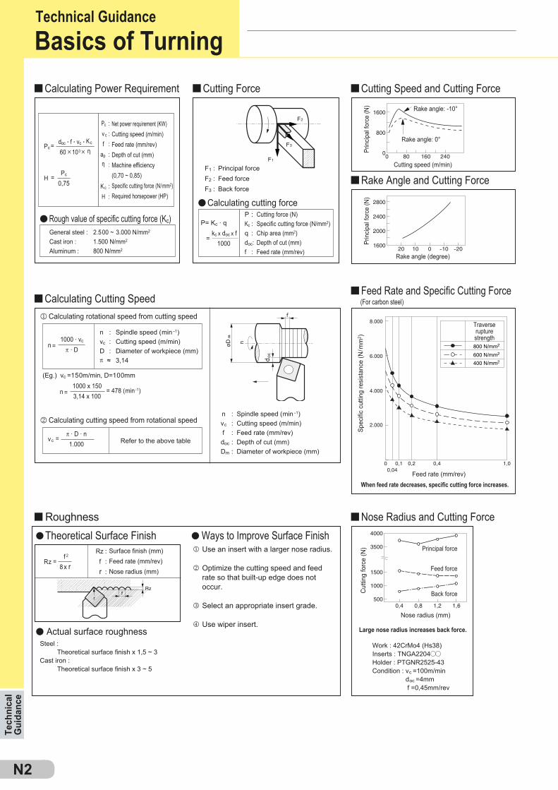
Pc
0,75H =
Rz : f : r :
j
k
l
m
n :vc :D :π ≈
vc =150m/min, D=100mm
F2
F3
F1
F1 :F2 :F3 :
1000 . vc
π . Dn =
π . D . n1.000
vc =
1000 x 1503,14 x 100
n =
rf
Rz
1600
800
0240160800
1600
2000
2400
2800
20 10 0 -10 -20
500
1000
1500
3500
4000
0,4 0,8 1,2 1,6
=
m
n
l l
Pc : vc : f :ap : η :
Kc : H :
f 2
8 x r
Back force
Feed force
Principal force
doc . f . vc . Kc
60 5103 5 ηPc =
Surface finish (mm)Feed rate (mm/rev)Nose radius (mm)
Steel : Theoretical surface finish x 1,5 ~ 3Cast iron : Theoretical surface finish x 3 ~ 5
Use an insert with a larger nose radius.
Optimize the cutting speed and feed rate so that built-up edge does not occur.
Select an appropriate insert grade.
Use wiper insert.
Work : 42CrMo4 (Hs38)Inserts : TNGA2204Holder : PTGNR2525-43Condition : vc =100m/min
doc =4mm f =0,45mm/rev
Large nose radius increases back force.
Nose radius (mm)
Cut
ting
forc
e (N
)
(Eg.)
Feed rate (mm/rev)
Calculating rotational speed from cutting speed
Calculating cutting speed from rotational speed
(For carbon steel)
Spindle speed (min-1)Cutting speed (m/min)Diameter of workpiece (mm)3,14
Net power requirement (KW)Cutting speed (m/min)Feed rate (mm/rev)Depth of cut (mm)Machine efficiency (0,70 ~ 0,85)Specific cutting force (N/mm2)Required horsepower (HP)
General steel : 2.500 ~ 3.000 N/mm2
Cast iron : 1.500 N/mm2
Aluminum : 800 N/mm2
Spindle speed (min-1)Cutting speed (m/min)Feed rate (mm/rev)Depth of cut (mm)Diameter of workpiece (mm)
Principal forceFeed forceBack force
Cutting force (N)Specific cutting force (N/mm2)Chip area (mm2)Depth of cut (mm)Feed rate (mm/rev)
Refer to the above table
Prin
cipal
forc
e (N
)
Cutting speed (m/min)
Prin
cipal
forc
e (N
)
Rake angle (degree)
Spec
ific
cutti
ng re
sist
ance
(N/m
m2 )
Traverse rupture strength
When feed rate decreases, specific cutting force increases.
Rake angle: 0°
Rake angle: -10°
Technical Guidance
Calculating cutting forceRough value of specific cutting force (Kc)
Actual surface roughness
Tech
nica
l G
uida
nce
Basics of TurningCalculating Power Requirement Cutting Force Cutting Speed and Cutting Force
Rake Angle and Cutting Force
Feed Rate and Specific Cutting Force
Nose Radius and Cutting ForceTheoretical Surface Finish
Calculating Cutting Speed
Ways to Improve Surface FinishRoughness
n :vc : f :doc :Dm :
d oc
P :Kc :q :doc:f :
P= Kc . q kc x doc x f 1000
N3
1~5
67
8
9 10
11
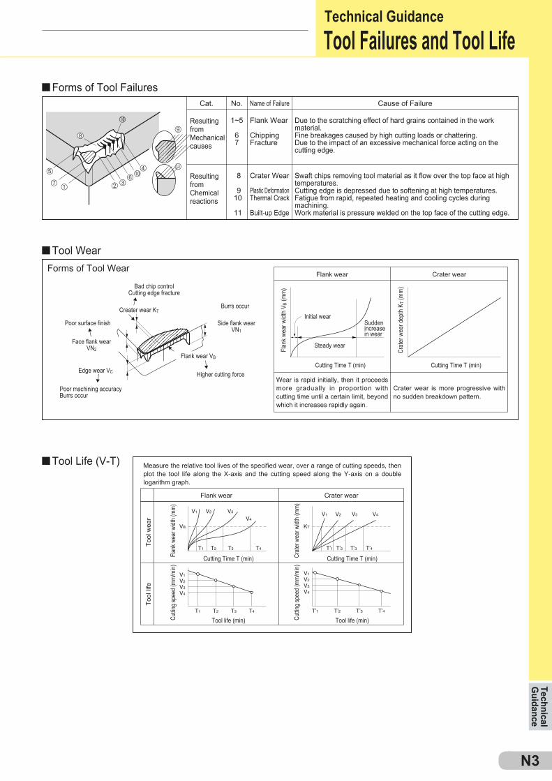
VB
V1
T1 T2 T3 T4
V2 V3
V4
V1
V2
V3
V4
T’1 T’2 T’3 T’4
V1
V2
V3
V4
T1 T2 T3 T4
KT
V1
T’1 T’2 T’3 T’4
V3 V4V2
Tool
life
Cuttin
g spe
ed (m
m/mi
n)
Tool life (min) Cuttin
g spe
ed (m
m/mi
n)
Tool life (min)
Crater wear is more progressive with no sudden breakdown pattern.
Flank wear
Measure the relative tool lives of the specified wear, over a range of cutting speeds, then plot the tool life along the X-axis and the cutting speed along the Y-axis on a double logarithm graph.
Tool
wea
r
Crater wear
Wear is rapid initially, then it proceeds more gradually in proportion with cutting time until a certain limit, beyond which it increases rapidly again.
Flan
k wea
r widt
h V B
(mm
)
Cutting Time T (min)
Flank
wea
r widt
h (mm
)
Cutting Time T (min) Crate
r wea
r widt
h (mm
)
Cutting Time T (min)
Steady wear
Crat
er w
ear d
epth
KT (
mm
)
Cutting Time T (min)
Initial wearSuddenincreasein wear
Bad chip controlCutting edge fracture
Poor machining accuracyBurrs occur
Face flank wearVN2
Side flank wearVN1
Creater wear KT
Poor surface finish
Edge wear VC
Flank wear VB
Higher cutting force
Burrs occur
Cat.
Resulting from Mechanical causes
Resulting from Chemical reactions
No. Name of Failure
Flank Wear
ChippingFracture
Crater Wear
Plastic DeformationThermal Crack
Built-up Edge
Cause of Failure
Due to the scratching effect of hard grains contained in the work material.Fine breakages caused by high cutting loads or chattering.Due to the impact of an excessive mechanical force acting on the cutting edge.
Swaft chips removing tool material as it flow over the top face at high temperatures.Cutting edge is depressed due to softening at high temperatures.Fatigue from rapid, repeated heating and cooling cycles during machining.Work material is pressure welded on the top face of the cutting edge.
Flank wear Crater wearForms of Tool Wear
Technical GuidanceTool Failures and Tool Life
Forms of Tool Failures
Tool Wear
Tool Life (V-T)
Technical G
uidance
N4
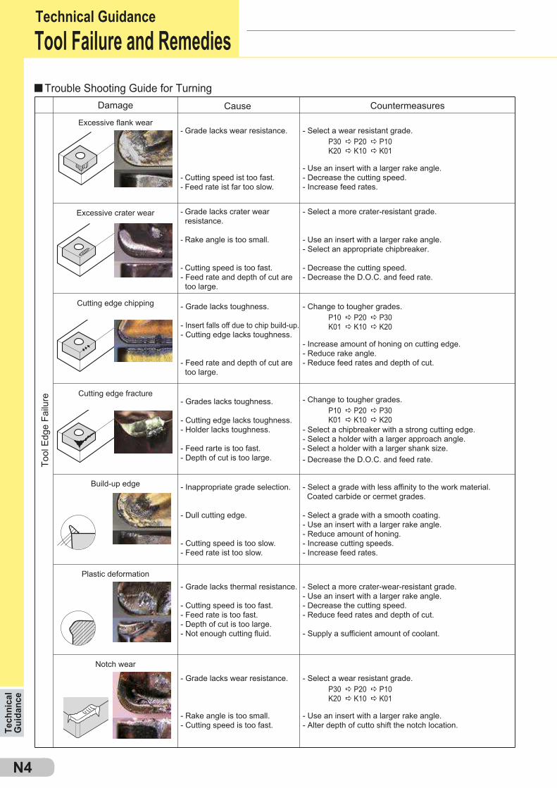
Damage
- Select a wear resistant grade. P30 a P20 a P10
K20 a K10 a K01
- Use an insert with a larger rake angle.- Alter depth of cutto shift the notch location.
Tool
Edg
e Fa
ilure
Countermeasures
- Grade lacks wear resistance.
- Cutting speed ist too fast.- Feed rate ist far too slow.
- Select a wear resistant grade. P30 a P20 a P10
K20 a K10 a K01
- Use an insert with a larger rake angle.- Decrease the cutting speed.- Increase feed rates.
- Grade lacks crater wear resistance.
- Rake angle is too small.
- Cutting speed is too fast.- Feed rate and depth of cut are too large.
- Select a more crater-resistant grade.
- Use an insert with a larger rake angle.- Select an appropriate chipbreaker.
- Decrease the cutting speed. - Decrease the D.O.C. and feed rate.
- Grade lacks toughness.
- Insert falls off due to chip build-up.- Cutting edge lacks toughness.
- Feed rate and depth of cut are too large.
- Change to tougher grades. P10 a P20 a P30
K01 a K10 a K20
- Increase amount of honing on cutting edge.- Reduce rake angle.- Reduce feed rates and depth of cut.
- Grades lacks toughness.
- Cutting edge lacks toughness.- Holder lacks toughness.
- Feed rarte is too fast.- Depth of cut is too large.
- Change to tougher grades. P10 a P20 a P30
K01 a K10 a K20- Select a chipbreaker with a strong cutting edge.- Select a holder with a larger approach angle.- Select a holder with a larger shank size.- Decrease the D.O.C. and feed rate.
- Inappropriate grade selection.
- Dull cutting edge.
- Cutting speed is too slow.- Feed rate ist too slow.
- Select a grade with less affinity to the work material. Coated carbide or cermet grades.
- Select a grade with a smooth coating.- Use an insert with a larger rake angle.- Reduce amount of honing.- Increase cutting speeds.- Increase feed rates.
Plastic deformation- Grade lacks thermal resistance.
- Cutting speed is too fast.- Feed rate is too fast.- Depth of cut is too large.- Not enough cutting fluid.
- Select a more crater-wear-resistant grade.- Use an insert with a larger rake angle.- Decrease the cutting speed.- Reduce feed rates and depth of cut.
- Supply a sufficient amount of coolant.
- Grade lacks wear resistance.
- Rake angle is too small.- Cutting speed is too fast.
Notch wear
Cutting edge chipping
Cutting edge fracture
Build-up edge
Excessive crater wear
Excessive flank wear
Tech
nica
l G
uida
nce
Technical GuidanceTool Failure and Remedies
Trouble Shooting Guide for TurningCause
N5
A B C D E
5 5
5 ~ 5
{
f1
t1
f2>f1
t2>t1
4,0
2,0
0,1 0,2 0,3 0,4 0,5
0,2 0,25 0,3 0,35
0,2 0,25 0,3 0,35
f f
t1
t2>t1
2 < 11
f f
t1
t2>t1
t2r1
r2 < r1
*
1,6
0,8
0,4
45°
15°
a b c d
k
l
j
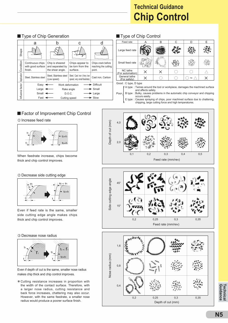
Good : C type, D type
Poor
A type : Twines around the tool or workpiece, damages the machined surface and affects safety.
B type : Bulky, causes problems in the automatic chip conveyor and chipping occurs easily.
E type : Causes spraying of chips, poor machined surface due to chattering, chipping, large cutting force and high temperatures.
When feedrate increase, chips become thick and chip control improves.
Dep
th o
f cut
(mm
)Si
de c
uttin
g ed
ge a
ngle
Nos
e ra
dius
(mm
)
Feed rate (mm/rev)
Even if feed rate is the same, smaller side cutting edge angle makes chips thick and chip control improves.
Cutting resistance increases in proportion with the width of the contact surface. Therefore, with a larger nose radius, cutting resistance and back force increases, chattering may also occur. However, with the same feedrate, a smaller nose radius would produce a poorer surface finish.
Even if depth of cut is the same, smaller nose radius makes chip thick and chip control improves.
Depth of cut (mm)
Feed rate (mm/rev)
Feed rate
Large feed rate
Small feed rate
NC lathe(For automation)
General lathe(For safety)
Shap
eC
ondi
tion
Applic
ation
Influ
ence
facto
r
Continuous chips with good surface finish.
Chip is sheared and separated by the shear angle.
Chips appear to be torn from the surface.
Chips crack before reaching the cutting point.
Steel, Stainless steel Steel, Stainless steel (Low speed)
Steel, Cast iron (Very low speed, very small feedrate) Cast iron, Carbon
DifficultSmallLargeSlow
EasyLargeSmallFast
Work deformationRake angle
D.O.C.Cutting speed
Technical G
uidanceTechnical GuidanceChip Control
Decrease side cutting edge
Decrease nose radius
Increase feed rate
Type of Chip Generation
Factor of Improvement Chip Control
Type of Chip Control
N6
–––s––– – – – – –––5––– – – l– –
jkl
1.800 800 200 – 1.400 600 160 – 1.000 400 120 –
l l
l
l
l
l
Pc0,75
H =
Q = (cm3/min)
π 5 D 5 n1.000
vc =
Pc = (kW)
( )
vf
vf
v f
z 5 n
A
Pc :
H :
Q :
woc :
v f :
doc :
η :
Kc :
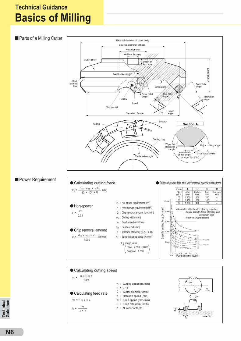
Values in the table show the following properties: - Tensile strength (N/mm2) for alloy steel and carbon steel - Hardness (HB) for cast iron
Front relief angle
d oc
v f = f t 5 z 5 n
vc : π ≈ D : n : v f : f t : z :
Cutting speed (m/min)3,14Cutter diameter (mm)Rotation speed (rpm)Feed speed (mm/min)Feed rate (mm/tooth)Number of teeth
f t
f t =
doc 5 woc 5 v f
1.000
doc . woc . v f . Kc
60 5 106 5 η Alloy steel
Work-piece
No.Carbon
steelCast iron
Aluminum alloy
Net power requirement (kW)
Horsepower requirement (HP)
Chip removal amount (cm3/min)
Cutting width (mm)
Feed speed (mm/min)
Depth of cut (mm)
Machine efficiency (0,70 ~ 0,85)
Specific cutting forrce (N/mm2)
Eg. rough value Steel : 2.500 ~ 3.000 Cast iron : 1.500
Feed rate (mm/tooth)
Spec
ific cu
tting
forc
e (N
/mm
2 )
Setting ring
Radial rake angleInward dish
(if trail angle)or wiper flat (if 0°)
Major cutting edge
Chamfered corner
Wiper flat clearance
angle
Section A
Setting ring
Chip pocket
Diameter of cutter
Back locating
face
Locator
Relief angle
Width of key way
Hole diameter
External diameter of boss
External diameter of cutter body
True rake angle Inclination
angle
Approach angle
Ove
rall
heig
ht
Clamp
Cutter Body
Insert
Depth of key way
Axial rake angle
Tech
nica
l G
uida
nce
Technical GuidanceBasics of Milling
Parts of a Milling Cutter
Power RequirementCalculating cutting force Relation between feed rate, work material, specific cutting force
Horsepower
Chip removal amount
Calculating cutting speed
Calculating feed rate
Screw
N7
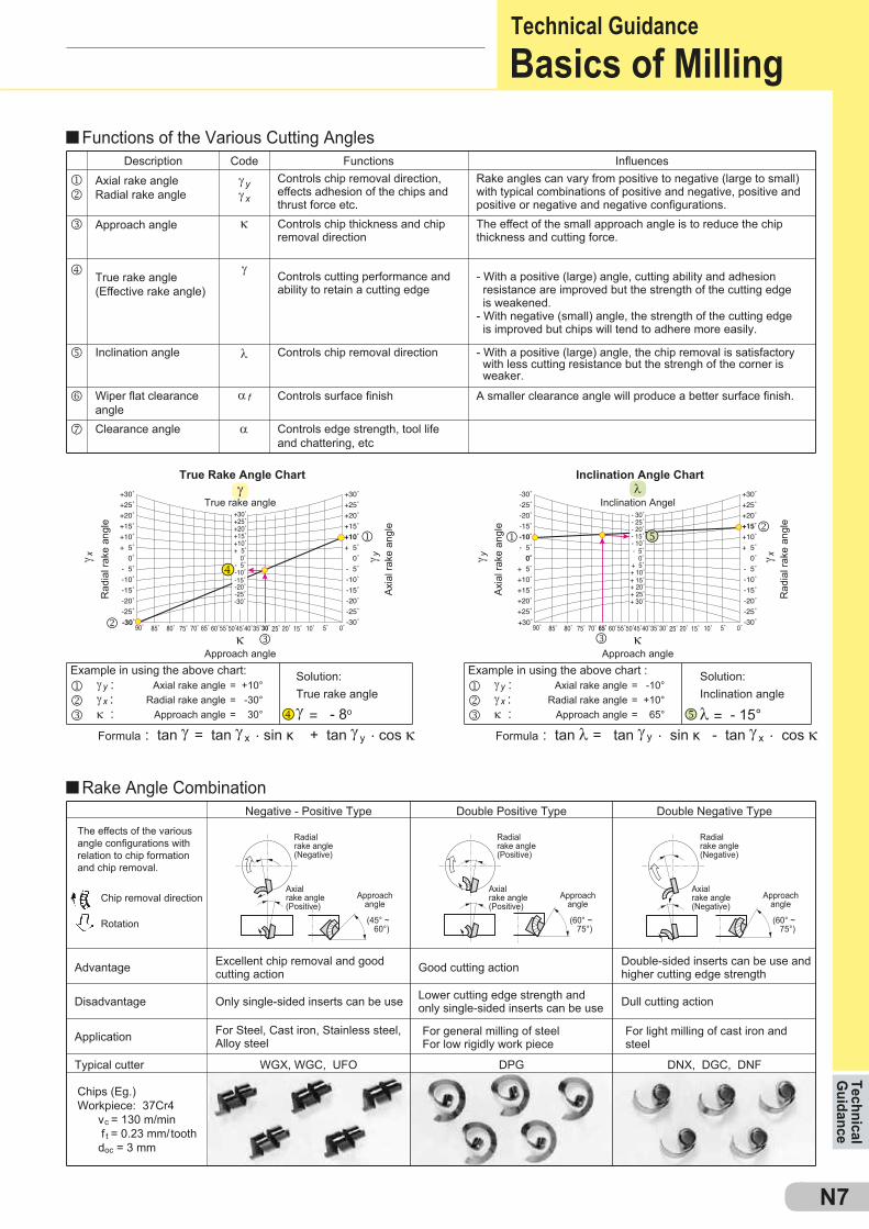
γyγx
κ
γ
α f
: tan γ = tan γ x . sin κ + tan γ y . cos κ : tan λ = tan γ y . sin κ - tan γ x . cos κ
jk
l
m
n
o
p
γ = - 8o λ = - 15°
α
λ
WGX, WGC, UFO DPG DNX, DGC, DNF
(45° ~ 60°)
(60° ~ 75°)
(60° ~ 75°)
j γy :k γx :l κ :
= +10°= -30°= 30°
= -10°= +10°= 65°
j γy :k γx :l κ :
γ yγ x γ y γ x
j
l l
jk
kκκ
λγ
n
n
m
m
True rake angle Inclination Angel
The effects of the various angle configurations with relation to chip formation and chip removal.
Excellent chip removal and good cutting action Good cutting action Double-sided inserts can be use and
higher cutting edge strength
Negative - Positive Type Double Positive Type Double Negative Type
Disadvantage
Typical cutter
Only single-sided inserts can be use
For general milling of steelFor low rigidly work piece
For light milling of cast iron and steel
For Steel, Cast iron, Stainless steel, Alloy steelApplication
Chips (Eg.)Workpiece: 37Cr4 vc = 130 m/min f t = 0.23 mm/tooth doc = 3 mm
Axialrake angle(Positive)
Approach angle
Advantage
Lower cutting edge strength and only single-sided inserts can be use Dull cutting action
Radial rake angle (Negative)
Axialrake angle(Positive)
Approach angle
Radial rake angle (Positive)
Axialrake angle(Negative)
Approach angle
Radial rake angle (Negative)
Rotation
Chip removal direction
FormulaFormula
Example in using the above chart: Example in using the above chart :Solution:True rake angle
Solution:Inclination angle
Axial rake angleRadial rake angle
Approach angle
Axial rake angleRadial rake angle
Approach angle
True Rake Angle Chart Inclination Angle Chart
Approach angle Approach angle
Rad
ial r
ake
angl
e
Axia
l rak
e an
gle
Axia
l rak
e an
gle
Rad
ial r
ake
angl
e
Axial rake angleRadial rake angle
DescriptionControls chip removal direction,effects adhesion of the chips and thrust force etc.
FunctionsCodeRake angles can vary from positive to negative (large to small)with typical combinations of positive and negative, positive andpositive or negative and negative configurations.
Influences
The effect of the small approach angle is to reduce the chipthickness and cutting force.
Approach angle
True rake angle(Effective rake angle)
Inclination angle
Wiper flat clearanceangleClearance angle
Controls chip thickness and chipremoval direction
Controls cutting performance and ability to retain a cutting edge
Controls chip removal direction
Controls surface finish
Controls edge strength, tool lifeand chattering, etc
- With a positive (large) angle, cutting ability and adhesion resistance are improved but the strength of the cutting edge is weakened.- With negative (small) angle, the strength of the cutting edge is improved but chips will tend to adhere more easily.
- With a positive (large) angle, the chip removal is satisfactory with less cutting resistance but the strengh of the corner is weaker.
A smaller clearance angle will produce a better surface finish.
Technical G
uidanceTechnical GuidanceBasics of Milling
Functions of the Various Cutting Angles
Rake Angle Combination
N8
A
A
B
B
C
D
F2
F3
F1
F
E
N
F
E
N
F
N
E
E
F
N
HC
HF
HW
h
HC
f f
HW
: 28’: 6’
CD
2020
15
10
5
2020
15
10
5
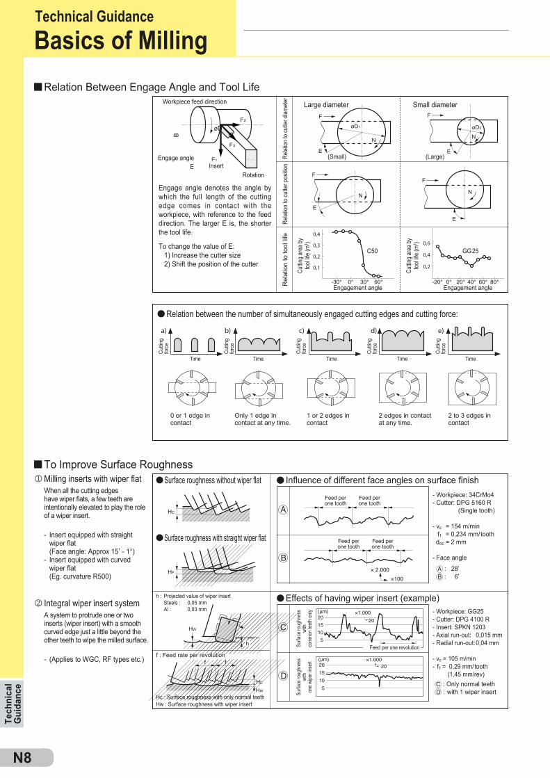
E
C50 GG25
B
øD
l
ll
l
j
k l
f : Feed rate per revolution
Hc : Surface roughness with only normal teethHw : Surface roughness with wiper insert
: Only normal teeth: with 1 wiper insert
- Workpiece: GG25- Cutter: DPG 4100 R- Insert: SPKN 1203- Axial run-out: 0,015 mm- Radial run-out: 0,04 mm
- vc = 105 m/min- f t = 0,29 mm/tooth (1,45 mm/rev)
A system to protrude one or two inserts (wiper insert) with a smooth curved edge just a little beyond the other teeth to wipe the milled surface.
- (Applies to WGC, RF types etc.)
Effects of having wiper insert (example)h : Projected value of wiper insert Steels : 0,05 mm Al : 0,03 mm
Surfa
ce ro
ughn
ess
with
comm
on te
eth on
ly
Surfa
ce ro
ughn
ess
with
one w
iper in
sert
- Workpiece: 34CrMo4- Cutter: DPG 5160 R (Single tooth)
- vc = 154 m/min f t = 0,234 mm/tooth doc = 2 mm
- Face angle
When all the cutting edges have wiper flats, a few teeth are intentionally elevated to play the role of a wiper insert.
- Insert equipped with straight wiper flat (Face angle: Approx 15’ - 1°)- Insert equipped with curved wiper flat (Eg. curvature R500)
Influence of different face angles on surface finishSurface roughness without wiper flat
Surface roughness with straight wiper flat
Feed per one tooth
Feed per one tooth
Feed per one tooth
Feed per one tooth
0 or 1 edge in contact
Only 1 edge in contact at any time.
1 or 2 edges in contact
2 edges in contact at any time.
2 to 3 edges in contact
Relation between the number of simultaneously engaged cutting edges and cutting force:
Cuttin
g are
a by
tool li
fe (m
3 )
Cuttin
g are
a by
tool li
fe (m
3 )
(Small)
Engagement angle Engagement angle
(Large)
Large diameter Small diameter
Engage angle denotes the angle by which the full length of the cutting edge comes in contact with the workpiece, with reference to the feed direction. The larger E is, the shorter the tool life.
To change the value of E: 1) Increase the cutter size 2) Shift the position of the cutter
Relat
ion to
cutte
r diam
eter
Relat
ion to
cutte
r pos
ition
Rel
atio
n to
tool
life
Workpiece feed direction
Engage angleInsert
Rotation
Tech
nica
l G
uida
nce
Technical GuidanceBasics of Milling
Relation Between Engage Angle and Tool Life
To Improve Surface RoughnessMilling inserts with wiper flat
Integral wiper insert system
Feed per one revolution
Cuttin
gfo
rce
Cuttin
gfo
rce
Cuttin
gfo
rce
Cuttin
gfo
rce
Cuttin
gfo
rce
Time Time Time Time Time

N9
DA1000 (SUMIDIA)
DA1000 (SUMIDIA)
Unsatisfactory Chip Control
- Select cutter with good chip removal features.- Reduce number of teeth.- Enlarge chip pocket.
- Reduce feed rates.
- Select a high rake cutter with sharp cutting edges- Use an irregular pitched cutter.- Improve workpiece and cutter clamp rigidity.
- Select a cutter with sharp cutting edges.
- Increase feed rates.
- Select a large approach angle.- Select a sharp cutting edge insert (G g L).- Reduce feed rates.
Tool Design
Cutting ConditionsTool Design
Others
Tool DesignCutting Conditions
Tool Design
Cutting Conditions
Oth
ers
Chattering
- Recommended cutter: WaveMill WGX type + FG breaker DGC type + FG breaker
- Recommended cutter: WaveMill WGX type
- Recommended cutter: WaveMill WGX type
- Recommended cutters:
For steel: WaveMill WGX type For cast iron: DNX type For Non-ferrous alloy: High speed cutter for aluminium RF type
WGC typeT250A
(Cermet)
CutterInsertFin
ishing
* marked cutters can be fitted with wiper inserts.
FMU typeBN700
(SUMIBORON)
RF typeDA1000
(SUMIDIA)
Edge Chipping on Workpiece
Burr on Workpiece
- Select an adhesion resistant grade. Carbide g Cermet
- Increase cutting speeds.
- Improve axial run-out of cutting edges. (Use a cutter with less run-out) (Attach correct inserts)
- Use wiper inserts.- Use special purpose cutters designed for finishing.
- If it is due to excessive low speeds or very low feed rates, select an adhesion resistant grade.- If it is due to thermal cracking, select a thermal impact resistant grade.
- Select appropriate conditions with regards to the particular application.
- Select a negative-positive (or negative) cutter configuration with a large approach angle.- Reinforce the cutting edge (Honing).- Select a strong edge insert (G g H).- Increase insert size - (Thickness in particular).
Tool Material
Cutting Conditions
Tool Design
Tool Material
Cutting Conditions
Tool Design
Partial Fracture of Cutting Edges
UnsatisfactoryMachined Surface Finish
- Recommended insert grades
- Recommended cutter: WaveMill WGX type
- Insert thickness: 3,18 g 4,76mm
- Insert type: Standard g Strong edge type
- Cutting conditions: Refer to recommended conditions listed in the general catalogue
Steel Cast Iron Non-Ferrous AlloyWGX type*
ACP200(Coated Carbide)
CutterInsertRo
ughin
g DGC type*ACK200
(Coated Carbide)
FF type*H1 (Carbide)
DL1000 (Coated Carbide)
- Recommended insert gradesSteel Cast Iron
ACP300(Coated Carbide)Roughing ACK300
(Coated Carbide)
- Recommended cutter: WaveMill WGX type- Cutting conditions: Refer to recommended conditions listed in the general catalogue
ACP300 (Coated Carbide)Roughing ACK300 (Coated Carbide)
Steel Cast Iron
ACK200 (Coated Carbide) DL1000 (Coated Carbide)
Trouble
Cut
ting
Edge
Fai
lure
Basic Remedies Remedy Examples
- Select tougher grade. P10 a P20 a P30 K01 a K10 a K20
- Reduce feed rates.
- Select a negative-positive cutter configuration with a large approach angle.- Reinforce the cutting edge (Honing).- Select a strong edge insert (G g H).
- Select a crater resistant grade.
- Reduce cutting speeds.- Reduce depth-of-cut and feed rate.
Tool Material
Cutting Conditions
Tool Design
Tool Material
Cutting Conditions
- Select a more wear resistant grade. Carbide
P30 a P20 a { Coated K20 a K10 Cermet
- Reduce cutting speeds.- Increase feedrate.
Tool Material
Cutting Conditions
Cutting Edge Chipping
Excessive Flank Wear
Excessive Crater Wear
- Recommended insert gradesSteel Cast Iron
ACP200 (Coated Carbide)Finishing ACK200 (Coated Carbide)
- Recommended insert gradesSteel
T250A (Cermet)Finishing
ACP100 (Coated Carbide)Roughing
Cast IronACK200 (Coated Carbide)
ACK200 (Coated Carbide)
Non-Ferrous Alloy
DL1000 (Coated Carbide)
- Recommended insert grades
T250A (Cermet)Finishing
ACP100 (Coated Carbide)Roughing
ACK200 (Coated Carbide)BN700 (SUMIBORON)
Non-Ferrous Alloy
Technical G
uidanceTechnical Guidance
Trouble Shooting Guide for Milling
Tool Failure and Remedies
N10
l
l
l
l
l
1.000 . vc
π . Dn =
D
R
R
D1Pf
D1
øD
D
doc
Woc
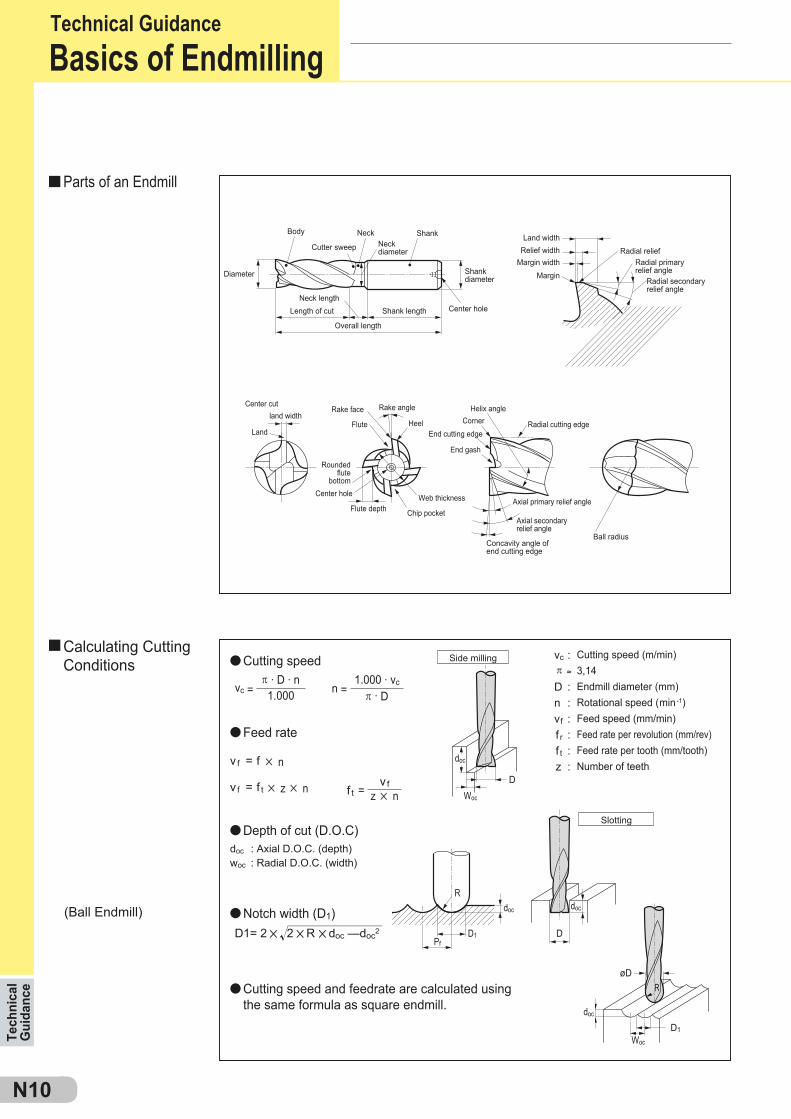
π . D . n1.000vc =
v f = f 5 n
doc : Axial D.O.C. (depth)woc : Radial D.O.C. (width)
D1= 2 5 2 5R 5doc —doc2
Side milling
Slotting
vc : π ≈
D :n :vf : f r : f t : z :
docdoc
doc
Woc
Cutting speed (m/min)3,14Endmill diameter (mm)Rotational speed (min-1)Feed speed (mm/min)Feed rate per revolution (mm/rev)Feed rate per tooth (mm/tooth)Number of teeth
v f = f t 5 z 5 n v fz 5 nf t =
Diameter
Body Neck
Cutter sweep Neckdiameter
Shank
Center hole
Radial relief
Ball radius
Radial primary relief angle
Radial secondaryrelief angle
Concavity angle of end cutting edge
Axial primary relief angle
Radial cutting edge
Helix angleCorner
End gash
Heel
Rake angle
Web thickness
Chip pocket
End cutting edge
Center hole
Rake face
FluteLand
Rounded flute
bottom
Flute depth
land widthCenter cut
Axial secondary relief angle
Land widthRelief width
Margin widthMargin
Neck lengthLength of cut Shank length
Overall length
Shankdiameter
Tech
nica
l G
uida
nce
Technical GuidanceBasics of Endmilling
(Ball Endmill)
Parts of an Endmill
Calculating Cutting Conditions Cutting speed
Feed rate
Depth of cut (D.O.C)
Notch width (D1)
Cutting speed and feedrate are calculated using the same formula as square endmill.
l l l l l0 50 100 150 200 250
0,08 -- --0,06 -- --0,04 -- --0,02 --
--
N11
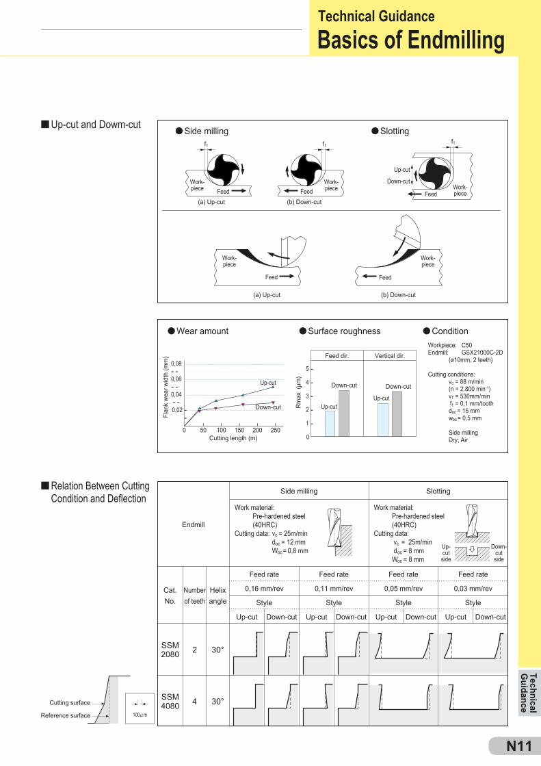
SSM2080
SSM4080
2
4
30°
30°
f t f tf t
Rm
ax (
µm)
l
l l l
l
5 --
4 --
3 --
2 --
1 --
0
Cat.No.
Number of teeth
Helix angle
0,16 mm/rev
Style
Up-cut Down-cut
0,11 mm/rev
Style
Up-cut Down-cut
0,05 mm/rev
Style
Up-cut Down-cut
0,03 mm/rev
Style
Up-cut Down-cut
Cutting surface
Reference surface
Workpiece: C50Endmill: GSX21000C-2D (ø10mm, 2 teeth)
Cutting conditions: vc = 88 m/min (n = 2.800 min-1) v f = 530mm/min
f t = 0,1 mm/tooth doc = 15 mm woc = 0,5 mm Side milling Dry, Air
Endmill
Side milling
Work material: Pre-hardened steel (40HRC)Cutting data: vc = 25m/min doc = 12 mm Woc = 0,8 mm
Slotting
Feed rate Feed rate Feed rate Feed rate
Work material: Pre-hardened steel (40HRC)Cutting data: vc = 25m/min doc = 8 mm Woc = 8 mm
(a) Up-cut
Work-piece
Work-piece
Work-piece
Feed Feed Feed
FeedFeed
Up-cut
Down-cutWork-piece Work-
piece(b) Down-cut
(a) Up-cut
Cutting length (m)
Down-cutside
Up-cutside
Down-cut
Feed dir. Vertical dir.
(b) Down-cut
Side milling Slotting
Flan
k w
ear w
idth
(mm
)
Up-cut
Down-cut Down-cut
Up-cut
Up-cut
Technical G
uidanceTechnical GuidanceBasics of Endmilling
Up-cut and Dowm-cut
Relation Between Cutting Condition and Deflection
Wear amount Surface roughness Condition
N12
Tech
nica
l G
uida
nce
Technical GuidanceTool Failure and Remedies
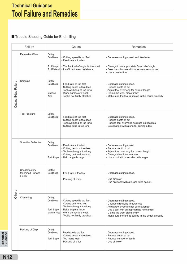
Trouble Shooting Guide for Endmilling
Excessive Wear- Cutting speed is too fast- Feed rate is too fast
- The flank relief angle ist too small- Insufficient wear resistance
- Decrease cutting speed and feed rate.
- Change to an appropriate flank relief angle.- Select a substrate with more wear resistance- Use a coated tool
- Feed rate ist too fast- Cutting depth is too deep- Tool overhang ist too long- Work clamps are weak- Tool is not firmly attached
- Decrease cutting speed.- Reduce depth of cut- Adjust tool overhang for correct length- Clamp the work piece firmly- Make sure the tool is seated in the chuck properly
Cutting Conditions
Tool ShapeTool Material
Chipping Cutting Conditions
MachineArea
- Feed rate ist too fast- Cutting depth is too deep- Tool overhang ist too long- Cutting edge is too long
- Decrease cutting speed.- Reduce depth of cut- Reduce tool overhang as much as possible- Select a tool with a shorter cutting edge
Tool Fracture Cutting Conditions
Cut
ting
Edge
Fai
lure
Oth
ers
Failure Cause Remedies
- Feed rate is too fast- Cutting depth is too deep- Tool overhang is too long- Cutting on the down-cut- Helix angle is large
- Decrease cutting speed.- Reduce depth of cut- Adjust tool overhang for correct length- Change directions to up-cut- Use a tool with a smaller helix angle
Shoulder Deflection Cutting Conditions
Tool Shape
- Cutting speed is too fast- Cutting on the up-cut- Tool overhang is too long- Rake angle is large- Work clamps are weak- Tool is not firmly attached
- Decrease cutting speed.
- Use air blow- Use an insert with a larger relief pocket.
Chattering Cutting Conditions
Tool ShapeMachine Area
- Feed rate is too fast- Cutting depth is too deep- Too many teeth- Packing of chips
- Decrease cutting speed.- Reduce depth of cut- Reduce number of teeth- Use air blow
Packing of Chip Cutting Conditions
Tool Shape
UnsatisfactoryMachined SurfaceFinish
Cutting Conditions - Feed rate is too fast
- Packing of chips
- Decrease cutting speed.- Change directions to down-cut- Adjust tool overhang for correct length- Use a tool with an appropriate rake angle- Clamp the work piece firmly- Make sure the tool is seated in the chuck properly
N13
*
0,2 0,3 0,40
2000
4000
6000
8000
0,2 0,3 0,40
20
40
60
A
B
Effects of thinning
Typical types of thinning
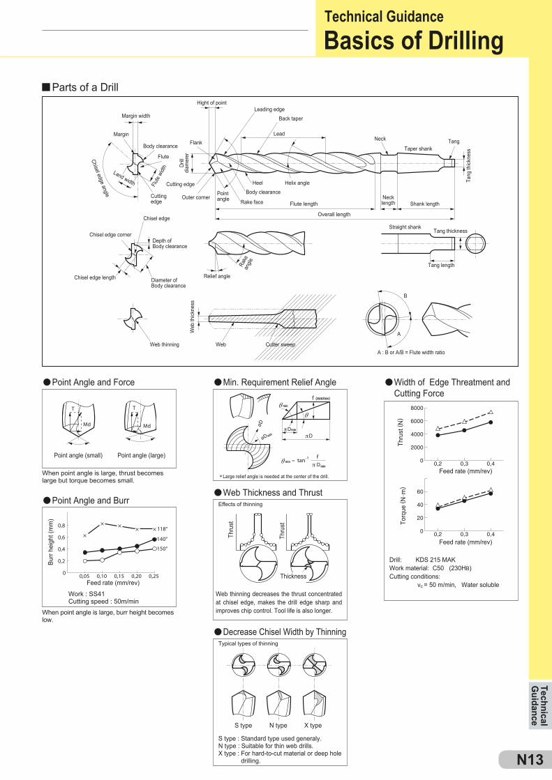
Work : SS41Cutting speed : 50m/min
When point angle is large, burr height becomes low.
Web thinning decreases the thrust concentrated at chisel edge, makes the drill edge sharp and improves chip control. Tool life is also longer.
Drill: KDS 215 MAKWork material: C50 (230HB)Cutting conditions: vc = 50 m/min, Water soluble
S type : Standard type used generaly.N type : Suitable for thin web drills.X type : For hard-to-cut material or deep hole
drilling.
S type N type X type
Feed rate (mm/rev)
Feed rate (mm/rev)Thickness
Thru
st
Thru
st
Burr
heig
ht (m
m)
When point angle is large, thrust becomes large but torque becomes small.
Large relief angle is needed at the center of the drill.
Web thinningA : B or A/B = Flute width ratio
Web
thick
ness
Web Cutter sweep
Feed rate (mm/rev)
Point angle (small) Point angle (large)
Thru
st ( N
)To
rque
( N. m
)
Flute length
Margin width
Hight of pointLeading edge
Back taper
Helix angle
Relief angle
Chisel edge
Chisel edge length
Chisel edge cornerRa
ke
angle
LeadNeck
Taper shank
Shank length
Straight shankTang thickness
Tang length
Neck length
Tang
thick
ness
Tang
Body clearance
Diameter ofBody clearance
Depth ofBody clearance
Rake facePointangle
Heel
Body clearance
Margin
Cutting edge
Cutting edge
Outer corner
Drill
diam
ererFlute
Flank
Chisel edge angle
Land width Flute
width
Overall length
Technical G
uidanceTechnical GuidanceBasics of Drilling
Parts of a Drill
Point Angle and BurrWeb Thickness and Thrust
Point Angle and Force Min. Requirement Relief Angle Width of Edge Threatment and Cutting Force
Decrease Chisel Width by Thinning
g
f
f
10 20 30 400
2
4
6
8
f = 0,3
f = 0,2
f = 0 1
10 20 30 400
12.000
10.000
8.000
6.000
4.000
2.000
f = 0,3
f = 0,2
f = 0,1
Vc=60m/min Vc=120m/min
N14
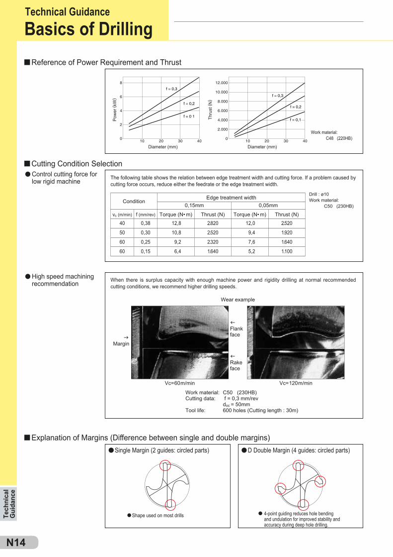
0,15mm 0,05mm
vc (m/min)
40 0,38 12,8 2.820 12,0 2.520
50 0,30 10,8 2.520 9,4 1.920
60 0,25 9,2 2.320 7,6 1.640
60 0,15 6,4 1.640 5,2 1.100
Shape used on most drills 4-point guiding reduces hole bending and undulation for improved stability and accuracy during deep hole drilling.
Torque (N• m) Torque (N• m) Thrust (N)f (mm/rev)
Wear example
Margin
Rake face
Flank face
Thrust (N)
Work material: C50 (230HB)Cutting data: f = 0,3 mm/rev doc = 50mmTool life: 600 holes (Cutting length : 30m)
When there is surplus capacity with enough machine power and rigidity drilling at normal recommended cutting conditions, we recommend higher drilling speeds.
ConditionEdge treatment width
The following table shows the relation between edge treatment width and cutting force. If a problem caused by cutting force occurs, reduce either the feedrate or the edge treatment width.
Drill : ø10Work material: C50 (230HB)
Work material: C48 (220HB)
Diameter (mm) Diameter (mm)
Pow
er ( k
W)
Thru
st ( N
)
Reference of Power Requirement and Thrust
Cutting Condition SelectionControl cutting force forlow rigid machine
High speed machining recommendation
Explanation of Margins (Difference between single and double margins)Single Margin (2 guides: circled parts) D Double Margin (4 guides: circled parts)
Tech
nica
l G
uida
nce
Technical GuidanceBasics of Drilling

N15
A
B
A
B
0
0,05
0,10
0,15
0,20
0,25
0,005 0,02 0,05
0,050,005 0,02 0,020,1 0,1
0,1
(mm)
0 0,05 (mm) 0 10 (kg)
0,005
0,09
2~3 mm
2~3 mm
Basics of Drilling
(n = 100~300 rpm) (f =0,15~0,2 mm/rev)
(Entrance) (Exit)
If the surface of the hole entrance or exit is slanted or uneven, decrease the feedrate to 0,1~0,15mm/rev at these points.
When using a long drill (e.g. XHGS type and XHT type), DAK type or SMDH-D type drills at high rotational speeds, the run-out of the drill tip may cause a position shift at the entry point making the drill hole bent and resulting in drill breakage.
Hole bend
Position shift
Step1
Short drill
No rotation
Drilling at recommended condition
Drilling at recommended condition
Pilot hole(1D, Same dia.)
Step1
Step2
Step2
Step3
Method 1.
Method 2. Low rotational speed minimizes centrifugal forces and prevents drill bending.
Run-out of the lip height B and thinning point A are important.
Drill run-out when mounted on the machine spindle must be within 0,03mm. If the run-out is large, the drilled hole will also be large causing an increase in the horizontal cutting force, which may result in drill breakage if the machine or work clamping is not rigid.
When use on a lathe, run-out at point A must be within 0,03mm, this value must be similar when taken at position B.
: The run-out accuracy of thinning point: The difference of lip height
Drill: MDS120MKWork material: C50 (230HB)Cutting data: vc=50 m/min, f=0,3 mm/rev, doc =38mm Water soluble
Peripheral run-out(mm)
Hole expansion Horizontal cutting force
Hol
e ex
pans
ion
Run-out: within 0,03mm
Run-out: within 0,03mmChuck
MDS 140 MK50Cvc = 50m/minf = 0,3mm/rev
Technical G
uidanceTechnical Guidance
Run-out Accuracy
Peripheral Run-out Accuracy when Tool Rotates
Peripheral Run-out Accuracy when Workpiece Rotates
Influence of Workpiece Surface
How to Use Long DrillProblem
Remedies
Workpiece with slanted or uneven surface
N16
Tech
nica
l G
uida
nce
Technical GuidanceU
nsat
isfa
ctor
y C
hip
Con
trol
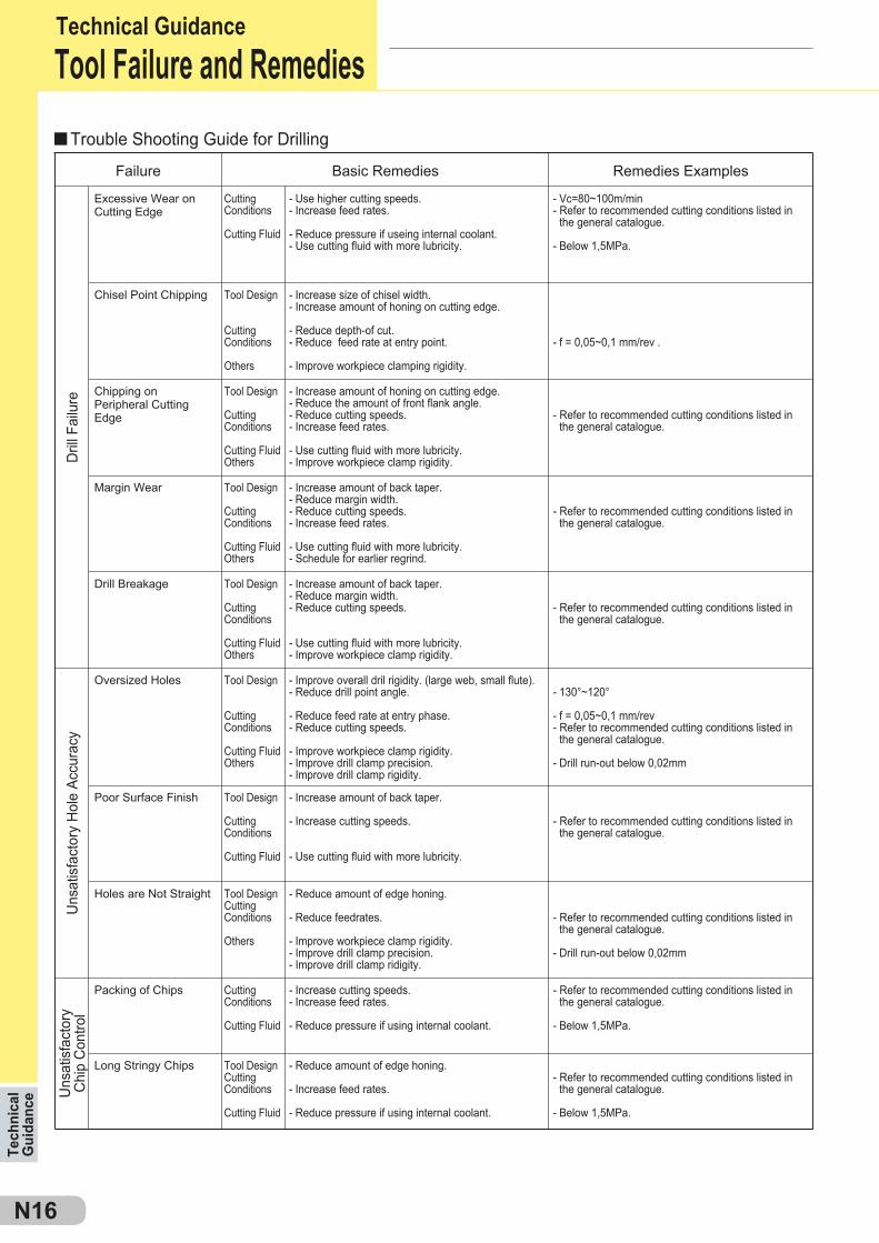
Packing of Chips - Increase cutting speeds.- Increase feed rates.
- Reduce pressure if using internal coolant.
Cutting Conditions
Cutting Fluid
Long Stringy Chips - Reduce amount of edge honing.
- Increase feed rates.
- Reduce pressure if using internal coolant.
- Refer to recommended cutting conditions listed in the general catalogue.
- Below 1,5MPa.
- Refer to recommended cutting conditions listed in the general catalogue.
- Below 1,5MPa.
Tool DesignCutting Conditions
Cutting Fluid
Uns
atis
fact
ory
Hol
e Ac
cura
cy
Margin Wear - Increase amount of back taper.- Reduce margin width.- Reduce cutting speeds.- Increase feed rates.
- Use cutting fluid with more lubricity.- Schedule for earlier regrind.
Tool Design
Cutting Conditions
Cutting FluidOthers
Drill Breakage - Increase amount of back taper.- Reduce margin width.- Reduce cutting speeds.
- Use cutting fluid with more lubricity.- Improve workpiece clamp rigidity.
Tool Design
Cutting Conditions
Cutting FluidOthers
Oversized Holes - Improve overall dril rigidity. (large web, small flute).- Reduce drill point angle.
- Reduce feed rate at entry phase.- Reduce cutting speeds.
- Improve workpiece clamp rigidity.- Improve drill clamp precision.- Improve drill clamp rigidity.
Tool Design
Cutting Conditions
Cutting FluidOthers
Poor Surface Finish - Increase amount of back taper.
- Increase cutting speeds.
- Use cutting fluid with more lubricity.
Tool Design
Cutting Conditions
Cutting Fluid
Holes are Not Straight - Reduce amount of edge honing.
- Reduce feedrates.
- Improve workpiece clamp rigidity.- Improve drill clamp precision.- Improve drill clamp ridigity.
Tool DesignCutting Conditions
Others
- Refer to recommended cutting conditions listed in the general catalogue.
- Refer to recommended cutting conditions listed in the general catalogue.
- 130°~120°
- f = 0,05~0,1 mm/rev- Refer to recommended cutting conditions listed in the general catalogue.
- Drill run-out below 0,02mm
- Refer to recommended cutting conditions listed in the general catalogue.
- Refer to recommended cutting conditions listed in the general catalogue.
- Drill run-out below 0,02mm
Excessive Wear onCutting Edge
- Use higher cutting speeds.- Increase feed rates.
- Reduce pressure if useing internal coolant.- Use cutting fluid with more lubricity.
- Vc=80~100m/min- Refer to recommended cutting conditions listed in the general catalogue.
- Below 1,5MPa.
Cutting Conditions
Cutting Fluid
Dril
l Fai
lure
Failure Basic Remedies Remedies Examples
Chisel Point Chipping - Increase size of chisel width.- Increase amount of honing on cutting edge.
- Reduce depth-of cut.- Reduce feed rate at entry point.
- Improve workpiece clamping rigidity.
Tool Design
Cutting Conditions
Others
Chipping on Peripheral CuttingEdge
- Increase amount of honing on cutting edge.- Reduce the amount of front flank angle.- Reduce cutting speeds.- Increase feed rates.
- Use cutting fluid with more lubricity.- Improve workpiece clamp rigidity.
Tool Design
Cutting Conditions
Cutting FluidOthers
- f = 0,05~0,1 mm/rev .
- Refer to recommended cutting conditions listed in the general catalogue.
Trouble Shooting Guide for Drilling
Tool Failure and Remedies
N17
SUMIBORON
400 80 120 1600
0,1
0,2
0,3
BN250 Vc=120BN250 Vc=150BN250 Vc=180
ff
40 45 50 55 60 65
10
150
100
50
030 50 70
20
0,3
0,25
0,2
0,15
0,1
0,05
040 60 80 100 120 140
300
200
100
0 0,05 0,10
45(HS)
106N
70
50
30
400
300
200
0
-10
-20
C55HRC24
34CrMo4HRC65
SUMIBORON
F1F2F3
F2
F3
F1
0,05
100
00,10
0,05
100
00,10
Technical G
uidanceTechnical Guidance
Constant Feedrate Variable Feedrate
Previous edge position
Stationary notch location Shifting notch location
Machining output (pcs.)
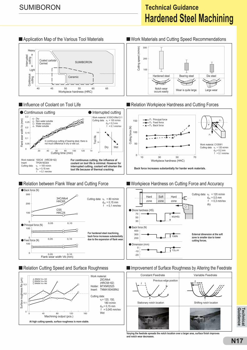
At high cutting speeds, surface roughness is more stable.
Varying the feedrate spreads the notch location over a larger area, surface finish improves and notch wear decreases.
Surfa
ce ro
ughn
ess R
a (μ
m) Work material:
25CrMo4 (HRC58~62)Holder: MTXNR2525Insert: TNMA160408NU
Cutting data: vc= 120, 150, 180 m/min doc = 0,15 mm f = 0,045 mm/rev Wet
Cutting time (min)
Workpiece hardness (HRC)
For hardened steel machining, back force increases substantially due to the expansion of flank wear.
External dimension at the soft zone is smaller due to lower cutting forces.
Back force increases substantially for harder work materials.
For continuous cutting, the influence of coolant on tool life is minimal. However for interrupted cutting, coolant will shorten the tool life because of thermal cracking.
Flan
k wea
r widt
h VB
(mm
)
Cuttin
g fo
rce
(N)
Tool
life
DryNon water solubleWater emulsionWater soluble
WetDry
In continuous cutting of bearing steel, there is not much difference in dry or wet cut.
Work material: 100Cr6 (HRC58~62)Insert: TPGN160304Cutting data: vc = 100 m/min doc = 0,15 mm f = 0,1 mm/rev
Cutting data: vc = 80 m/min doc = 0,15 mm f = 0,1 mm/rev
Cutting data: vc = 120 m/min doc = 0,5 mm f = 0,3 mm/rev dry
Work material: C105W1Cutting data: vc = 120 m/min doc = 0,2 mm f = 0,1 mm/rev
Softzone
Hardzone
Hardzone
Workpiece hardness (HRC)
Cuttin
g sp
eed
(m/m
in)
Hardened steel
Notch wearoccurs easily Wear is quite large. Large wear
Bearing steel Die steelCeramic
Coated carbideCermet
Work material: X155CrVMo12-1Cutting data: vc = 100 m/min doc = 0,2 mm f = 0,1 mm/rev
Light
Heavy
Inte
rrupt
ed
cuttin
gCo
ntinu
ous
cuttin
g
Principal forceFeed forceBack force
Hardened Steel MachiningApplication Map of the Various Tool Materials Work Materials and Cutting Speed Recommendations
Influence of Coolant on Tool Life Relation Workpiece Hardness and Cutting Forces
Relation between Flank Wear and Cutting Force Workpiece Hardness on Cutting Force and Accuracy
Relation Cutting Speed and Surface Roughness Improvement of Surface Roughness by Altering the Feedrate
Back force (N)
Continuous cutting Interrupted cutting
Principal force (N)
Shore hardness (HS)
Back force (N)
Dimension (mm)Feed force (N)
Flank wear width VB (mm)

0 20 40 60 80 100 120 140 160 180 200
0,25
0,20
0,15
0,10
0,05
03000
50
100
150
200
250
450 600 750 900 1050 1200 1350 1500
GGGGG
Crater wear
(vc ≥ 200 m/min)
2,5 5 7,5 10 12,50
0,1
0,2
0,3
0,4 10
8
6
4
2
0200 400
BNS800BN7000BNC500
BNX10
BNC500
BN7000
Vc=600m/min
Vc=600m/min Vc=1000m/min
Vc=1500m/min
Vc=400m/min
N18
SUMIBORON
BNS800BN7000BNC500
Wet
Number of pass Cutting speed (m/min)
Cutting data:doc = 0,5 mm, ft = 0,15 mm/tooth
Flan
k wea
r widt
h (m
m)
Num
ber o
f pas
s
Dry cutting is recommended for high speed milling of cast iron with SUMIBORON.
Typical thermal crack
Dry
Ceramic
Work material: GG25Tool material: BN700Cutting data: doc = 0,5 mm, f t = 0,1 mm/tooth, DRY
- High speed machining Vc = 2000m/min- Surface Roughness Rz=3,2 (Ra=1,0)- Running cost is reduced because of economical insert- Easy insert setting with the aid of a setting gauge- Safe, anti-centrifugal force construction for high speed
conditions
Surfa
ce ro
ughn
ess R
max (
mm)
cutting speed Vc (m/min)
Structure
Pearlite + FerritePearlite
Dry
Wet
Tool
wea
r sha
pe
Matrix
WET( Water soluble)
DRY
For machining cast iron with SUMIBORON, cutting speeds (Vc) should be 200m/min and above. WET cutting is recommended.
Flan
k w
ear w
idth
VB
(mm
)
Cutting length (km)
DRY
WET
Work material: GG25Insert: SNGN120408(BN500)Cutting data: vc = 450 m/min doc = 0,25 mm f = 0,15 mm/rev Continuous cutting
Machine: N/C latheWork material: GG25 (HB200)Holder: MTJNP2525Insert: TNMA160408(BN500)Cutting data: vc = 110~280 m/min doc = 0,1 mm f = 0,1 mm/rev WET
GG: Grey cast iron GGG: Ductile cast iron
Good f Surface roughness Ra (μm)
CeramicCoated carbideCermet
Goo
d f
Siz
e ac
cura
cy
Tool life ratio
Cut
ting
spee
d v
c (m
/min
)
Tool life ratio
Cut
ting
spee
d v
c (m
/min
)
CeramicCoated carbideCermet
CeramicCoated carbideCermet
Cast Iron Machining
SUMIBORON BN Finish Mill EASY
Advantages of Using SUMIBORON for Cast Iron Machining
Turning
Milling
Higher accuracy Longer tool life at higher cutting speeds
Cast iron structure and wear shape examples
Tech
nica
l G
uida
nce
Technical Guidance
SUMIBORON
N19
Vc = 300m/min Vc = 500m/min
0,5mm
BN700 K10
DA150
BN700 DA150K10
DA150
BNS800 (Vc=300m/min) BNS800 (Vc=300m/min)
BN700
BNX20 BN700
Technical G
uidance
BNS800(Vc=300m/min, After 2km Cutting)
Whisker reinforced ceramic(Vc=50m/min, After 10m Cutting)
BNS800(After 2km of cutting)
Competitor‘s solid CBN(After 2km of cutting)
Chipping
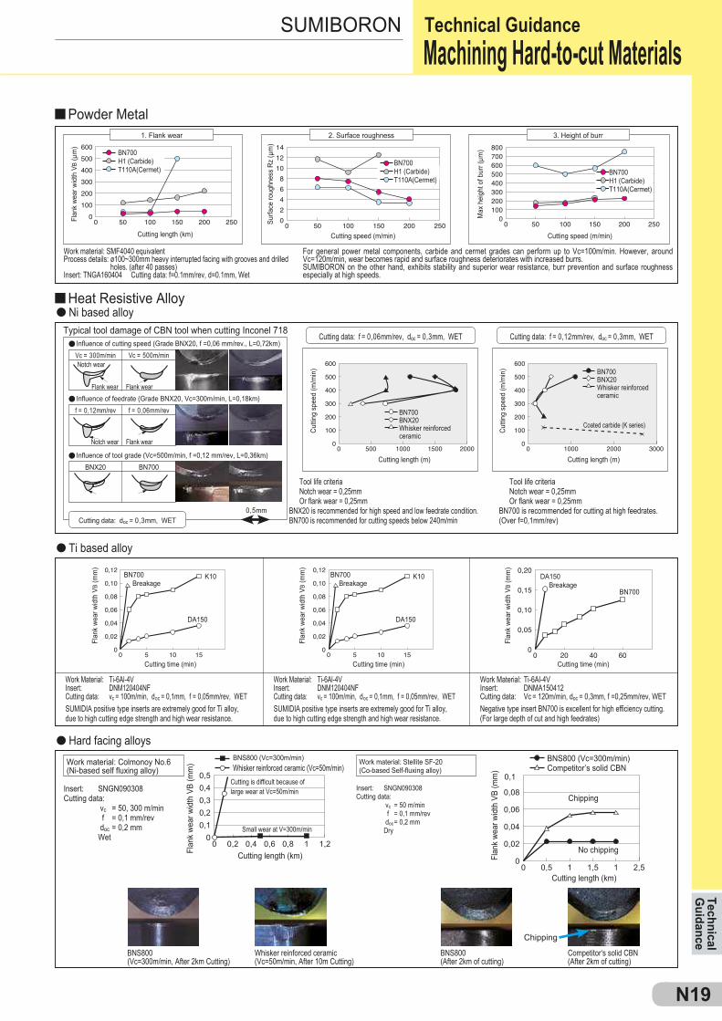
Small wear at V=300m/min
Cutting is difficult because oflarge wear at Vc=50m/min
Work material: Colmonoy No.6(Ni-based self fluxing alloy)
Work material: Stellite SF-20(Co-based Self-fluxing alloy)
Flan
k we
ar w
idth
VB
(mm
)
Flan
k we
ar w
idth
VB
(mm
)
Cutting time (min) Cutting time (min)
Breakage Breakage Breakage
Flan
k we
ar w
idth
VB
(mm
)
Cutting length (km) Flan
k we
ar w
idth
VB
(mm
)
Cutting length (km)
Chipping
No chipping
Insert: SNGN090308Cutting data: vc = 50, 300 m/min f = 0,1 mm/rev doc = 0,2 mm Wet
Insert: SNGN090308Cutting data: vc = 50 m/min f = 0,1 mm/rev doc = 0,2 mm Dry
Tool life criteriaNotch wear = 0,25mmOr flank wear = 0,25mm
BNX20 is recommended for high speed and low feedrate condition. BN700 is recommended for cutting speeds below 240m/min
Tool life criteriaNotch wear = 0,25mmOr flank wear = 0,25mm
BN700 is recommended for cutting at high feedrates. (Over f=0,1mm/rev)Cutting data: doc = 0,3mm, WET
SUMIDIA positive type inserts are extremely good for Ti alloy, due to high cutting edge strength and high wear resistance.
Work Material: Ti-6Al-4VInsert: DNM120404NFCutting data: vc = 100m/min, doc = 0,1mm, f = 0,05mm/rev, WET
SUMIDIA positive type inserts are extremely good for Ti alloy, due to high cutting edge strength and high wear resistance.
Work Material: Ti-6Al-4VInsert: DNM120404NFCutting data: vc = 100m/min, doc = 0,1mm, f = 0,05mm/rev, WET
Negative type insert BN700 is excellent for high efficiency cutting. (For large depth of cut and high feedrates)
Work Material: Ti-6Al-4VInsert: DNMA150412Cutting data: Vc = 120m/min, doc = 0,3mm, f =0,25mm/rev, WET
Flan
k we
ar w
idth
VB
(mm
)
Cutting time (min)
Whisker reinforced ceramic (Vc=50m/min) Competitor’s solid CBN
f = 0,12mm/rev f = 0,06mm/rev
For general power metal components, carbide and cermet grades can perform up to Vc=100m/min. However, around Vc=120m/min, wear becomes rapid and surface roughness deteriorates with increased burrs.SUMIBORON on the other hand, exhibits stability and superior wear resistance, burr prevention and surface roughness especially at high speeds.
Work material: SMF4040 equivalentProcess details: ø100~300mm heavy interrupted facing with grooves and drilled
holes. (after 40 passes)Insert: TNGA160404 Cutting data: f=0.1mm/rev, d=0.1mm, Wet
Typical tool damage of CBN tool when cutting Inconel 718
Flan
k we
ar w
idth
VB
(μm
)
Cutting length (km)
Surfa
ce ro
ughn
ess
Rz (μ
m)
Cutting speed (m/min)
Cutti
ng s
peed
(m/m
in)
Cutting length (m) Cutting length (m)
Max
hei
ght o
f bur
r (μm
)
Cutting speed (m/min)
BN700H1 (Carbide)T110A(Cermet)
Notch wear
Flank wear Flank wear
BN700H1 (Carbide)T110A(Cermet)
BN700H1 (Carbide)T110A(Cermet)
Cutti
ng s
peed
(m/m
in)
Coated carbide (K series)
Notch wear Flank wear
BN700BNX20Whisker reinforced ceramic
BN700BNX20Whisker reinforced ceramic
1. Flank wear 2. Surface roughness 3. Height of burr
Cutting data: f = 0,06mm/rev, doc = 0,3mm, WET Cutting data: f = 0,12mm/rev, doc = 0,3mm, WET
Machining Hard-to-cut Materials
Influence of cutting speed (Grade BNX20, f =0,06 mm/rev., L=0,72km)
Powder Metal
Heat Resistive AlloyNi based alloy
Ti based alloy
Hard facing alloys
Influence of feedrate (Grade BNX20, Vc=300m/min, L=0,18km)
Influence of tool grade (Vc=500m/min, f =0,12 mm/rev, L=0,36km)
Technical Guidance
F
F
FFF
F
FFFF
F
FFFF
F
F
F
FFFFFF
F
F
FF
FFF
FFFFFFF
N20
SUMIBORON
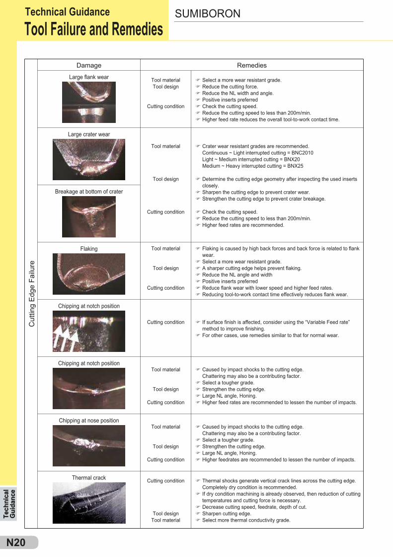
Damage Remedies
Tech
nica
l G
uida
nce
Cut
ting
Edge
Fai
lure
Thermal crack Cutting condition
Tool designTool material
Thermal shocks generate vertical crack lines across the cutting edge. Completely dry condition is recommended.If dry condition machining is already observed, then reduction of cutting temperatures and cutting force is necessary.Decrease cutting speed, feedrate, depth of cut.Sharpen cutting edge.Select more thermal conductivity grade.
Chipping at nose positionTool material
Tool design
Cutting condition
Caused by impact shocks to the cutting edge.Chattering may also be a contributing factor.Select a tougher grade.Strengthen the cutting edge.Large NL angle, Honing.Higher feedrates are recommended to lessen the number of impacts.
Chipping at notch positionTool material
Tool design
Cutting condition
Caused by impact shocks to the cutting edge.Chattering may also be a contributing factor.Select a tougher grade.Strengthen the cutting edge.Large NL angle, Honing.Higher feed rates are recommended to lessen the number of impacts.
Chipping at notch position
Cutting condition If surface finish is affected, consider using the “Variable Feed rate” method to improve finishing.For other cases, use remedies similar to that for normal wear.
Flaking Tool material
Tool design
Cutting condition
Flaking is caused by high back forces and back force is related to flank wear.Select a more wear resistant grade.A sharper cutting edge helps prevent flaking.Reduce the NL angle and widthPositive inserts preferredReduce flank wear with lower speed and higher feed rates.Reducing tool-to-work contact time effectively reduces flank wear.
Breakage at bottom of crater
Large crater wear
Tool material
Tool design
Cutting condition
Crater wear resistant grades are recommended.Continuous ~ Light interrupted cutting = BNC2010Light ~ Medium interrupted cutting = BNX20Medium ~ Heavy interrupted cutting = BNX25
Determine the cutting edge geometry after inspecting the used inserts closely.Sharpen the cutting edge to prevent crater wear.Strengthen the cutting edge to prevent crater breakage.
Check the cutting speed.Reduce the cutting speed to less than 200m/min.Higher feed rates are recommended.
Large flank wear Tool materialTool design
Cutting condition
Select a more wear resistant grade.Reduce the cutting force.Reduce the NL width and angle.Positive inserts preferredCheck the cutting speed.Reduce the cutting speed to less than 200m/min.Higher feed rate reduces the overall tool-to-work contact time.
Technical GuidanceTool Failure and Remedies
Tech
nica
l G
uida
nce
N21
l
l
l
l
l
l
l
l
l
ll
l
l
l
l
l
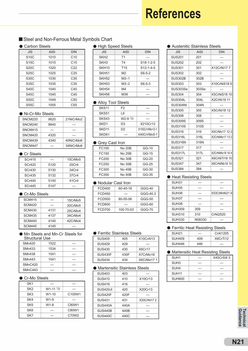
JIS AISI DINS10C 1010 C10S15C 1015 C15S20C 1020 C22S25C 1025 C25S30C 1030 C30S35C 1035 C35S40C 1040 C40S45C 1045 C45S50C 1049 C50S55C 1055 C55
JIS AISI DINSKH2 T1 —SKH3 T4 S18-1-2-5SKH10 T15 S12-1-4-5SKH51 M2 S6-5-2SKH52 M3–1 —SKH53 M3–2 S6-5-3SKH54 M4 —SKH56 M36 —
JIS AISI DINSUS201 201 —SUS202 202 —SUS301 301 X12CrNi17 7SUS302 302 —SUS302B 302B —SUS303 303 X10CrNiS18 9SUS303Se 303Se —SUS304 304 X5CrNiS18 10SUS304L 304L X2CrNi19 11SUS304NI 304N —SUS305 305 X5CrNi18 12SUS308 308 —SUS309S 309S —SUS310S 310S —SUS316 316 X5CrMo17 12 2SUS316L 316L X2CrNiMo17 13 2SUS316N 316N —SUS317 317 —SUS317L 317L X2CrNiMo18 16 4SUS321 321 X6CrNiTi18 10SUS347 347 X6CrNiNb18 10SUS384 384 —
SNCM220 8620 21NiCrMo2SNCM240 8640 —SNCM415 — —SNCM420 4320 —SNCM439 4340 40NiCrMo6SNCM447 — 34NiCrMo6
SCr415 — 15CrMo5SCr420 5120 20Cr4SCr430 5130 34Cr4SCr435 5132 37Cr4SCr440 5140 41Cr4SCr445 5147 —
SCM415 — 15CrMo5SCM420 — 20CrMo5SCM430 4131 25CrMo4SCM435 4137 34CrMo4SCM440 4140 42CrMo4SCM445 4145 —
SMn420 1522 —SMn433 1534 —SMn438 1541 —SMn443 1541 —SMnC420 — —SMnC443 — —
SK1 — —SK2 W1-11 1/2 —SK3 W1-10 C105W1SK4 W1-9 —SK5 W1-8 C80W1SK6 — C80W1SK7 — C70W2
SKS11 F2 —SKS51 L6 —SKS43 W2-9 1/2 —SKD1 D3 X210Cr12SKD11 D2 X155CrVMo12-1SKD61 — X40CrVMo5-1
FC100 No 20B GG-10FC150 No 25B GG-15FC200 No 30B GG-20FC250 No 35B GG-25FC300 No 45B GG-30FC350 No 50B GG-35
FCD400 60-40-18 GGG-40FCD450 — GGG-40.3FCD500 80-55-06 GGG-50FCD600 — GGG-60FCD700 100-70-03 GGG-70
SUS405 405 X10CrAl13SUS429 429 —SUS430 430 X6Cr17SUS430F 430F X7CrMo18SUS434 434 X6CrMo17 1
SUS403 403 —SUS410 410 X10Cr13SUS416 416 —SUS420JI 420 X20Cr13SUS420F 420F —SUS431 431 X20CrNi17 2SUS440A 440A —SUS440B 440B —SUS440C 440C —
SUH31 — —SUH35 — —SUH36 — X53CrMnNi21 9SUH37 — —SUH38 — —SUH309 309 —SUH310 310 CrNi2520SUH330 N08330 —
SUH21 — CrAl1205SUH409 409 X6CrTi12SUH446 446 —
SUH1 — X45CrSi9 3SUH3 — —SUH4 — —SUH11 — —SUH600 — —
Technical G
uidance
Steel and Non-Ferrous Metal Symbols Chart
References
Ni-Cr-Mo Steels
Cr Steels
Cr-Mo Steels
Cr-Mo Steels
Mn Steels and Mn-Cr Steels forStructural Use
Alloy Tool Steels
Grey Cast Iron
Nodular Cast Iron
Ferritic Stainless Steels
Martensitic Stainless Steels
Heat Resisting Steels
Ferritic Heat Resisting Steels
Martensitic Heat Resisting Steels
Austenitic Stainless SteelsHigh Speed SteelsCarbon Steels

— 85,6 — 68,0 76,9 940 97 —
— 85,3 — 67,5 76,5 920 96 —
— 85,0 — 67,0 76,1 900 95 —
767 84,7 — 66,4 75,7 880 93 —
757 84,4 — 65,9 75,3 860 92 —
745 84,1 — 65,3 74,8 840 91 —
733 83,8 — 64,7 74,3 820 90 —
722 83,4 — 64,0 73,8 800 88 —
712 — — — — — — —
710 83,0 — 63,3 73,3 780 87 —
698 82,6 — 62,5 72,6 760 86 —
684 82,2 — 61,8 72,1 740 — —
682 82,2 — 61,7 72,0 737 84 —
670 81,8 — 61,0 71,5 720 83 —
656 81,3 — 60,1 70,8 700 — —
653 81,2 — 60,0 70,7 697 81 —
647 81,1 — 59,7 70,5 690 — —
638 80,8 — 59,2 70,1 680 80 —
630 80,6 — 58,8 69,8 670 — —
627 80,5 — 58,7 69,8 667 79 —
601 79,8 — 57,3 68,7 640 77 —
578 79,1 — 56,0 67,7 615 75 —
555 78,4 — 54,7 66,7 591 73 2055
534 77,8 — 53,5 65,8 569 71 1985
514 76,9 — 52,1 64,7 547 70 1890
495 76,3 — 51,0 63,8 528 68 1820
477 75,6 — 49,6 62,7 508 66 1730
461 74,9 — 48,5 61,7 491 65 1670
444 74,2 — 47,1 60,8 472 63 1585
429 73,4 — 45,7 59,7 455 61 1510
415 72,8 — 44,5 58,8 440 59 1460
401 72,0 — 43,1 57,8 425 58 1390
388 71,4 — 41,8 56,8 410 56 1330
375 70,6 — 40,4 55,7 396 54 1270
363 70,0 — 39,1 54,6 383 52 1220
352 69,3 (110,0) 37,9 53,8 372 51 1180
341 68,7 (109,0) 36,6 52,8 360 50 1130
331 68,1 (108,5) 35,5 51,9 350 48 1095
321 67,5 (108,0) 34,3 50,1 339 47 1060
311 66,9 (107,5) 33,1 50,0 328 46 1025
302 66,3 (107,0) 32,1 49,3 319 45 1005
293 65,7 (106,0) 30,9 48,3 309 43 970
285 65,3 (105,5) 29,9 47,6 301 — 950
277 64,6 (104,5) 28,8 46,7 292 41 925
269 64,1 (104,0) 27,6 45,9 284 40 895
262 63,6 (103,0) 26,6 45,0 276 39 875
255 63,0 (102,0) 25,4 44,2 269 38 850
248 62,6 (101,0) 24,2 43,2 261 37 825
241 61,8 100,0 22,8 42,0 253 36 800
235 61,4 99,0 21,7 41,4 247 35 785
229 60,8 98,2 20,5 40,5 241 34 765
223 — 97,3 (18,8) — 234 — —
217 — 96,4 (17,5) — 228 33 725
212 — 95,5 (16,0) — 222 — 705
207 — 94,6 (15,2) — 218 32 690
201 — 93,8 (13,8) — 212 31 675
197 — 92,8 (12,7) — 207 30 655
192 — 91,9 (11,5) — 202 29 640
187 — 90,7 (10,0) — 196 — 620
183 — 90,0 (9,0) — 192 28 615
179 — 89,0 (8,0) — 188 27 600
174 — 87,8 (6,4) — 182 — 585
170 — 86,8 (5,4) — 178 26 570
167 — 86,0 (4,4) — 175 — 560
163 — 85,0 (3,3) — 171 25 545
156 — 82,9 (0,9) — 163 — 525
149 — 80,8 — — 156 23 505
143 — 78,7 — — 150 22 490
137 — 76,4 — — 143 21 460
131 — 74,0 — — 137 — 450
126 — 72,0 — — 132 20 435
121 — 69,8 — — 127 19 415
116 — 67,6 — — 122 18 400
111 — 65,7 — — 117 15 385
N22
1) Figures within the ( ) are not commonly used2) Rockwell A, C and D scales utilises a diamond brale3) 1 N/mm2 = 1 MPa
Rockwell Hardness VickersHardness
50kgf
(HV)
ShoreHardness
(HS)
TraverseRupture Strength(N/mm2)
„A“ ScaleDiamond,
brale 60kgf(HRA)
BrinellHardness10mm Ball 3.000kgf
(HB)
„B“ Scale100kgf
1/10“ Ball(HRB)
„C“ ScaleDiamond,
brale 150kgf(HRC)
„D“ ScaleDiamond,
brale 100kgf(HRD)
BrinellHardness
10mm Ball 3.000kgf
(HB)
Rockwell Hardness VickersHardness
50kgf
(HV)
ShoreHardness
(HS)
TraverseRupture Strength(N/mm2)
„A“ ScaleDiamond,
brale 60kgf(HRA)
„B“ Scale100kgf
1/10“ Ball(HRB)
„C“ ScaleDiamond,
brale 150kgf(HRC)
„D“ ScaleDiamond,
brale 100kgf(HRD)
Hardness Scale Comparision ChartApprox. metric value and Brinell hardness of steel
Tech
nica
l G
uida
nce
References
N23
h 1)Ry
h 2)Rz
Ra
Yp1
Yp2 Yp3 Yp4
Yp5
Yv1
(Yp1+Yp2+Yp3+Yp4+Yp5)+(Yv1+Yv2+Yv3+Yv4+Yv5)5
Rz=
Yv2 Yv3
Yv4 Yv5
m
h 1) Ry :h 2) Rz :
(0,05S)0,1S0,2S0,4S
(0,05Z)0,1Z0,2Z0,4Z
(0,013a)0,025a0,05a0,10a
—
0,8S 0,8Z 0,20a 0,25
1,6S3,2S6,3S
1,6Z3,2Z6,3Z
0,4a0,8a1,6a
0,8
12,5S(18S)25S
12,5Z(18Z)25Z
3,2a6,3a 2,5
(35S)50S
(70S)100S
(35Z)50Z
(70Z)100Z
12,5a25a
—
(140S)200S
(280S)400S
(560S)
(140Z)200Z
(280Z)400Z
(560Z)
(50a)(100a)
— —
Technical G
uidance
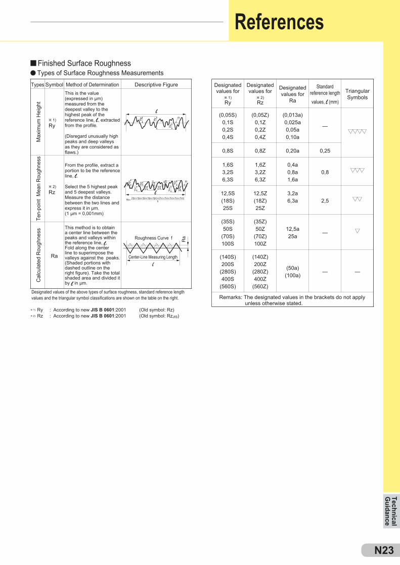
According to new JIS B 0601:2001 (Old symbol: Rz)According to new JIS B 0601:2001 (Old symbol: RzJIS)
Types Symbol Method of Determination Descriptive Figure
Max
imum
Hei
ght
This is the value (expressed in µm) measured from the deepest valley to the highest peak of the reference line, l, extracted from the profile.
(Disregard unusually high peaks and deep valleys as they are considered as flaws.)
Ten-
poin
t M
ean
Rou
ghne
ss
From the profile, extract a portion to be the reference line, l.
Select the 5 highest peak and 5 deepest valleys. Measure the distance between the two lines and express it in µm.(1 µm = 0,001mm)
Cal
cula
ted
Rou
ghne
ss
This method is to obtain a center line between the peaks and valleys within the reference line, l. Fold along the center line to superimpose the valleys against the peaks. (Shaded portions with dashed outline on the right figure). Take the total shaded area and divided it by l in µm.
Designated values of the above types of surface roughness, standard reference length values and the triangular symbol classifications are shown on the table on the right.
Designatedvalues for
h 1)Ry
Designatedvalues for
h 2)Rz
Designatedvalues for
Ra
Standard reference length values, l (mm)
TriangularSymbols
Remarks: The designated values in the brackets do not apply unless otherwise stated.
Center-Line Measuring Length
Roughness Curve f
Finished Surface Roughness
References
Types of Surface Roughness Measurements

N24
Tornillos ........................................................................
Tornillos, palancas, asientos de plaquita ................
Pasadores, Tuercas, Excéntricas .............................
Llaves .............................................................................
Repuestos
Piezas de repuesto
P1
P1–P8P
P1
P2-P4P4-P6P7P8
Screw ............................................................................Lever Pin, Shim, Nut.....................................................Shim Pin, Eccentric Pin ...............................................Wrench ..........................................................................
Spare Parts
Spare Parts
Repu
esto
sPiezas de repuestoTornillos
P2
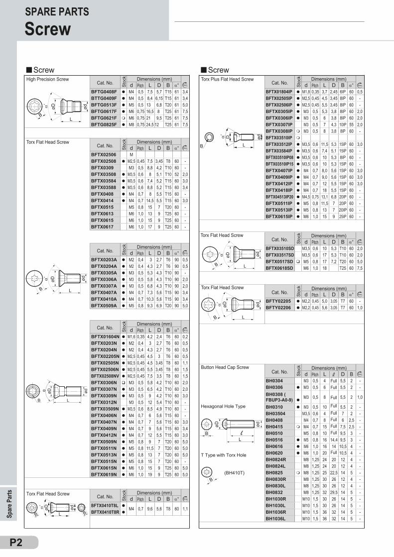
d L D B a°BFTG0408F l M4 0,5 7,5 5,7 T15 61 3,4BTTG0409F l M4 0,5 8,4 6,15 T15 61 3,4BFTG0513F l M5 0,5 13 6,8 T20 61 5,0BFTG0617F l M6 0,75 16,5 8 T25 61 7,5BFTG0621F m M6 0,75 21 9,5 T25 61 7,5BFTG0825F l M8 0,75 24,5 12 T25 61 7,5
d L D B a°BFTX02506 MBFTX02508 l M2,5 0,45 7,5 3,45 T8 60 -BFTX0309 M3 0,5 8,8 4,2 T10 60 -BFTX03508 l M3,5 0,6 8 5,1 T10 52 2,0BFTX03584 l M3,5 0,6 7,4 5,2 T15 60 3,0BFTX03588 l M3,5 0,6 8,8 5,2 T15 60 3,4BFTX0408 l M4 0,7 8 5,5 T15 60 -BFTX0414 l M4 0,7 14,5 5,5 T15 60 3,0BFTX0515 M5 0,8 15 7 T20 60 -BFTX0613 M6 1,0 13 9 T25 60 -BFTX0615 M6 1,0 15 9 T25 60 -BFTX0617 M6 1,0 17 9 T25 60 -
d L D B a°BFTX0203A l M2 0,4 3 2,7 T6 90 0,5BFTX0204A l M2 0,4 4,3 2,7 T6 90 0,5BFTX0305A l M3 0,5 5,3 4,3 T10 90 -BFTX0306A l M3 0,5 5,8 4,3 T10 90 2,0BFTX0307A l M3 0,5 6,8 4,3 T10 90 2,0BFTX0407A l M4 0,7 7,3 5,6 T15 90 3,4BFTX0410A l M4 0,7 10,3 5,6 T15 90 3,4BFTX0509A l M5 0,8 9,3 6,9 T20 90 5,0
d L D B a°BFTX01604N l M1,6 0,35 4,2 2,4 T6 60 0,2BFTX0203N l M2 0,4 3 2,7 T6 60 0,5BFTX0204N l M2 0,4 4,3 2,7 T6 60 0,5BFTX02205N l M2,5 0,45 4,5 3 T6 60 0,5BFTX02505N l M2,5 0,45 4,5 3,45 T8 60 1,1BFTX02506N l M2,5 0,45 5,5 3,45 T8 60 1,5BFTX02508NV l M2,5 0,45 7,5 3,5 T8 60 1,5BFTX0306N q M3 0,5 5,8 4,2 T10 60 2,0BFTX0307N l M3 0,5 6,5 4,2 T10 60 2,0BFTX0309N l M3 0,5 9 4,2 T10 60 3,0BFTX0312N M3 0,5 12 5,4 T10 60 -BFTX03509N l M3,5 0,6 8,5 4,9 T10 60 -BFTX0406N l M4 0,7 6 5,6 T15 60 -BFTX0407N l M4 0,7 7 5,6 T15 60 3,0BFTX0409N l M4 0,7 9 5,6 T15 60 3,4BFTX0412N l M4 0,7 12 5,5 T15 60 3,0BFTX0509N l M5 0,8 9 7 T20 60 5,0BFTX0511N l M5 0,8 11,5 7 T20 60 5,0BFTX0513N l M5 0,8 13 7 T20 60 5,0BFTX0515N l M5 0,8 15 7 T20 60 -BFTX0615N l M6 1,0 15 9 T25 60 5,0BFTX0619N l M6 1,0 19 9 T25 60 5,0
d L D B a°BFTX01804IP l M1,8 0,35 3,7 2,45 6IP 60 0,5BFTX02505IP l M2,5 0,45 4,5 3,45 8IP 60 -BFTX02506IP l M2,5 0,45 5,5 3,45 8IP 60 -BFTX0305IP l M3 0,5 5,3 3,8 8IP 60 2,0BFTX0306IP l M3 0,5 6 3,8 8IP 60 2,0BFTX0307IP M3 0,5 7 4,3 10IP 55 2,0BFTX0308IP m M3 0,5 8 3,8 8IP 60 -BFTX03510IP m
BFTX03512IP l M3,5 0,6 11,5 5,3 15IP 60 3,0BFTX03584IP l M3,5 0,6 7,4 5,1 15IP 60 -BFTX03510IP08 l M3,5 0,6 10 5,3 8IP 60 -BFTX03510IP15 l M3,5 0,6 10 5,3 15IP 60 -BFTX0407IP l M4 0,7 8,0 5,6 15IP 60 3,0BFTX0409IP l M4 0,7 9,0 5,6 15IP 60 3,0BFTX0412IP l M4 0,7 12 5,5 15IP 60 3,0BFTX0418IP l M4 0,7 18 5,5 15IP 60 -BFTX04513IP20 l M4,5 0,75 13,1 6,8 20IP 60 -BFTX0511IP l M5 0,8 11,5 7 20IP 60 -BFTX0513IP l M5 0,8 13 7 20IP 60 -BFTX0615IP l M6 1,0 15 9 25IP 60 -
d L D B a°BFTX0410T8L l M4 0,7 9,6 5,6 T8 60 1,1BFTX0410T8R l
B L
ødD
d L D B a°BFTX03510SD M3,5 0,6 10 5,3 T10 60 2,0BFTX03517SD M3,5 0,6 17 5,3 T10 60 2,0BFTX0517SD q M5 0,8 17 7,2 T20 60 5,0BFTX0618SD M6 1,0 18 T25 60 7,5
d L D B a°BFTY02205 l M2,2 0,45 5,0 3,05 T7 60 -BFTY02206 l M2,2 0,45 5,6 3,05 T7 60 1,0
d L D BBH0304 M3 0,5 4 5,5 2 -BH0306 l M3 0,5 6 5,5 2 -BH0308 ( FBUP3-A0-9) l M3 0,5 8 5,5 2 1,0
BH0310 l M3 0,5 10 5,5 2 -BH03504 M3,5 0,6 4 7 2 -BH0408 M4 0,7 8 6 2,5 -BH0415 m M4 0,7 15 7,5 2,5 -BH0510 M5 0,8 10 9,5 3 -BH0516 l M5 0,8 16 14,4 9,5 3 -BH0616 l M6 1,0 16 14 10,5 4 -BH0620 l M6 1,0 20 10,5 4 -BH0824R M8 1,25 24 20 12 4 -BH0824L M8 1,25 24 20 12 4 -BH0825 m M8 1,25 25 22,5 14 5 -BH0830R M8 1,25 30 26 12 4 -BH0830L M8 1,25 30 26 12 4 -BH0832 M8 1,25 32 29,5 14 5 -BH1030R M10 1,5 30 26 14 5 -BH1030L M10 1,5 30 26 14 5 -BH1036R M10 1,5 36 32 14 5 -BH1036L M10 1,5 36 32 14 5 -
Cat. No.Dimensions (mm)
Stoc
k
Cat. No.Dimensions (mm)
Stoc
k
Torx Plus Flat Head ScrewCat. No.
Dimensions (mm)
Stoc
k
Torx Flat Head Screw Cat. No.Dimensions (mm)
Stoc
k
Cat. No.Dimensions (mm)
Stoc
k
Pitch
Pitch
Pitch Pitch
Full
FullFull
FullFull
Full
Full
Cat. No.Dimensions (mm)
Stoc
k
Pitch
Pitch
Pitch
High Precision ScrewCat. No.
Dimensions (mm)
Stoc
k
PitchTorx Flat Head Screw
Cat. No.Dimensions (mm)
Stoc
k
PitchCat. No.Dimensions (mm)
Stoc
k
Spar
e Par
tsSPARE PARTSScrew
Screw Screw
Torx Flat Head Screw
Button Head Cap Screw
Hexagonal Hole Type
T Type with Torx Hole
FullFull
Torx Flat Head Screw
RepuestosPiezas de repuestoTornillos
P3
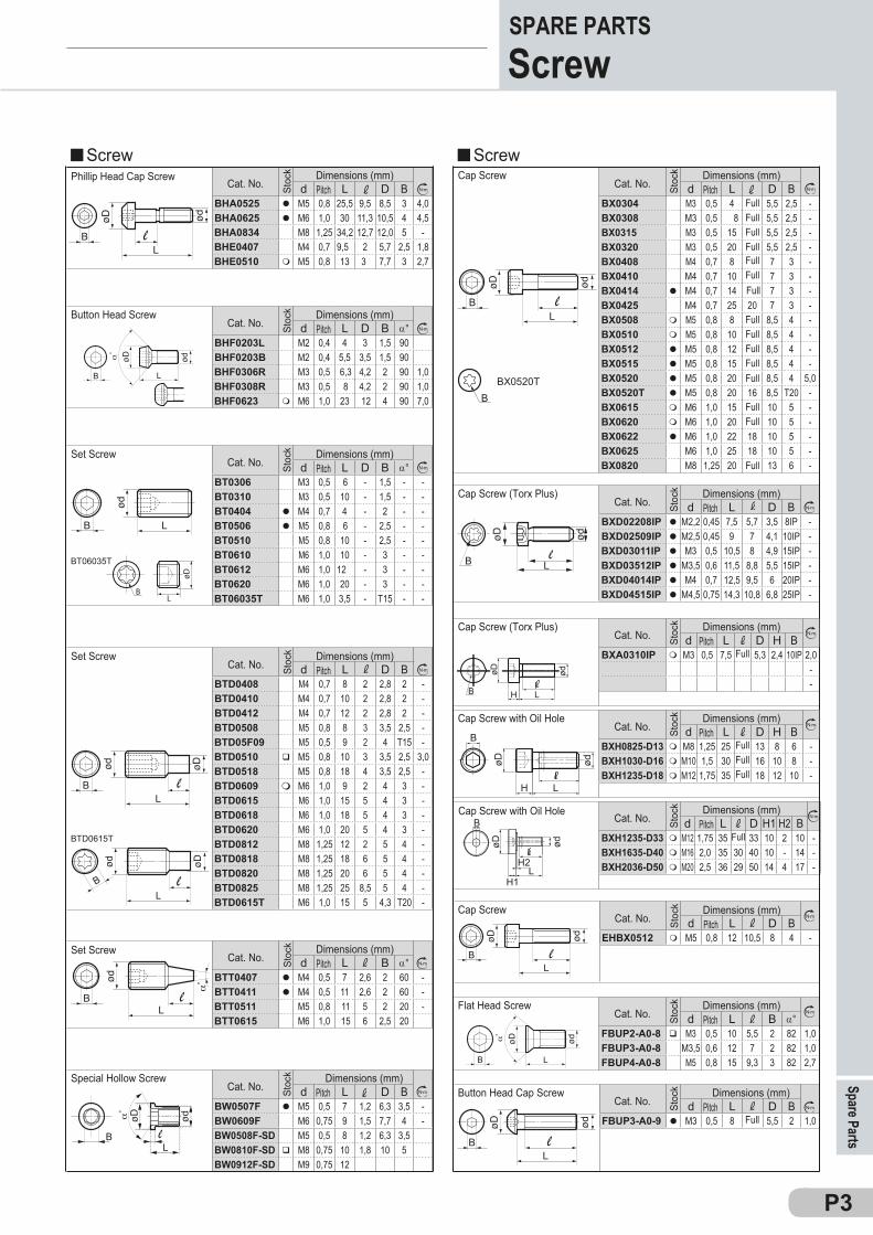
d L D BBHA0525 l M5 0,8 25,5 9,5 8,5 3 4,0BHA0625 l M6 1,0 30 11,3 10,5 4 4,5BHA0834 M8 1,25 34,2 12,7 12,0 5 -BHE0407 M4 0,7 9,5 2 5,7 2,5 1,8BHE0510 m M5 0,8 13 3 7,7 3 2,7
d L D B a°BHF0203L M2 0,4 4 3 1,5 90BHF0203B M2 0,4 5,5 3,5 1,5 90BHF0306R M3 0,5 6,3 4,2 2 90 1,0BHF0308R M3 0,5 8 4,2 2 90 1,0BHF0623 m M6 1,0 23 12 4 90 7,0
d L D B a°
BT0306 M3 0,5 6 - 1,5 - -BT0310 M3 0,5 10 - 1,5 - -BT0404 l M4 0,7 4 - 2 - -BT0506 l M5 0,8 6 - 2,5 - -BT0510 M5 0,8 10 - 2,5 - -BT0610 M6 1,0 10 - 3 - -BT0612 M6 1,0 12 - 3 - -BT0620 M6 1,0 20 - 3 - -BT06035T M6 1,0 3,5 - T15 - -
øD
LB
BT06035T
d L D BBTD0408 M4 0,7 8 2 2,8 2 -BTD0410 M4 0,7 10 2 2,8 2 -BTD0412 M4 0,7 12 2 2,8 2 -BTD0508 M5 0,8 8 3 3,5 2,5 -BTD05F09 M5 0,5 9 2 4 T15 -BTD0510 q M5 0,8 10 3 3,5 2,5 3,0BTD0518 M5 0,8 18 4 3,5 2,5 -BTD0609 m M6 1,0 9 2 4 3 -BTD0615 M6 1,0 15 5 4 3 -BTD0618 M6 1,0 18 5 4 3 -BTD0620 M6 1,0 20 5 4 3 -BTD0812 M8 1,25 12 2 5 4 -BTD0818 M8 1,25 18 6 5 4 -BTD0820 M8 1,25 20 6 5 4 -BTD0825 M8 1,25 25 8,5 5 4 -BTD0615T M6 1,0 15 5 4,3 T20 -
BTD0615T
d L B a°BTT0407 l M4 0,5 7 2,6 2 60 -BTT0411 l M4 0,5 11 2,6 2 60 -BTT0511 M5 0,8 11 5 2 20 -BTT0615 M6 1,0 15 6 2,5 20
d L D BBW0507F l M5 0,5 7 1,2 6,3 3,5 -BW0609F M6 0,75 9 1,5 7,7 4 -BW0508F-SD M5 0,5 8 1,2 6,3 3,5BW0810F-SD q M8 0,75 10 1,8 10 5BW0912F-SD M9 0,75 12
d L D BBX0304 M3 0,5 4 5,5 2,5 -BX0308 M3 0,5 8 5,5 2,5 -BX0315 M3 0,5 15 5,5 2,5 -BX0320 M3 0,5 20 5,5 2,5 -BX0408 M4 0,7 8 7 3 -BX0410 M4 0,7 10 7 3 -BX0414 l M4 0,7 14 7 3 -BX0425 M4 0,7 25 20 7 3 -BX0508 m M5 0,8 8 8,5 4 -BX0510 m M5 0,8 10 8,5 4 -BX0512 l M5 0,8 12 8,5 4 -BX0515 l M5 0,8 15 8,5 4 -BX0520 l M5 0,8 20 8,5 4 5,0BX0520T l M5 0,8 20 16 8,5 T20 -BX0615 m M6 1,0 15 10 5 -BX0620 m M6 1,0 20 10 5 -BX0622 l M6 1,0 22 18 10 5 -BX0625 M6 1,0 25 18 10 5 -BX0820 M8 1,25 20 13 6 -
d L D BEHBX0512 m M5 0,8 12 10,5 8 4 -
d L B a°FBUP2-A0-8 q M3 0,5 10 5,5 2 82 1,0FBUP3-A0-8 M3,5 0,6 12 7 2 82 1,0FBUP4-A0-8 M5 0,8 15 9,3 3 82 2,7
d L D BFBUP3-A0-9 l M3 0,5 8 5,5 2 1,0
BX0520T
d L D BBXD02208IP l M2,2 0,45 7,5 5,7 3,5 8IP -BXD02509IP l M2,5 0,45 9 7 4,1 10IP -BXD03011IP l M3 0,5 10,5 8 4,9 15IP -BXD03512IP l M3,5 0,6 11,5 8,8 5,5 15IP -BXD04014IP l M4 0,7 12,5 9,5 6 20IP -BXD04515IP l M4,5 0,75 14,3 10,8 6,8 25IP -
d L D H1 H2 BBXH1235-D33 m M12 1,75 35 33 10 2 10 -BXH1635-D40 m M16 2,0 35 30 40 10 - 14 -BXH2036-D50 m M20 2,5 36 29 50 14 4 17 -
d L D H BBXA0310IP m M3 0,5 7,5 5,3 2,4 10IP 2,0
--
d L D H BBXH0825-D13 m M8 1,25 25 13 8 6 -BXH1030-D16 m M10 1,5 30 16 10 8 -BXH1235-D18 m M12 1,75 35 18 12 10 -
øD ød
lLHB
lLH
ødøD
B
øD ød
l
LH1
H2
B
Cat. No.Dimensions (mm)
Stoc
k
Cat. No.Dimensions (mm)
Stoc
k
Cat. No.Dimensions (mm)
Stoc
k
Cat. No.Dimensions (mm)
Stoc
k
Cat. No.Dimensions (mm)
Stoc
k
Cat. No.Dimensions (mm)
Stoc
k
Pitch
Pitch
Pitch
Pitch
Pitch
Pitch
Cat. No.Dimensions (mm)
Stoc
k
Pitch
Spare PartsSPARE PARTSScrew
ScrewScrewPhillip Head Cap Screw
Button Head Screw
Set Screw
Set Screw
Set Screw
Cat. No.Dimensions (mm)
Stoc
k
PitchSpecial Hollow Screw
Cap Screw
FullFullFullFull
Full
FullFullFullFull
Full
Full
Cap Screw (Torx Plus)
Cat. No.Dimensions (mm)
Stoc
k
Pitch
Cat. No.Dimensions (mm)
Stoc
k
Pitch
Cap Screw
Cat. No.Dimensions (mm)
Stoc
k
Pitch
Cat. No.Dimensions (mm)
Stoc
k
Pitch
Button Head Cap Screw
Flat Head Screw
Full
FullFull
Full
Full
Cat. No.Dimensions (mm)
Stoc
k
Pitch
Cat. No.Dimensions (mm)
Stoc
k
Pitch
Full
FullFullFull
Full
Cap Screw (Torx Plus)
Cap Screw with Oil Hole
Cap Screw with Oil Hole

Repu
esto
sPiezas de repuestoTornillos, palancas, asientos
P4
d L D BFMJ l M4 0,5 15 5 6 3 -
d L D BWB4-8 M4 0,7 7,5 3 3,0 2 -WB5-10 l M5 0,8 10 4 3,8 2,5 -WB5-12 m M5 0,8 12 5 3,8 2,5 -WB6-13 m M6 1,0 13 5 4,5 3 -WB6-16 l M6 1,0 16 6 4,5 3 -WB6-20 q M6 1,0 20 8,5 4,5 3 -WB6-30 M6 1,0 30 12 4,5 3 -WB8-20 M8 1,25 20 8,5 6,2 4 -WB8-24 M8 1,25 24 8,5 6,2 4 -WB8-30 l M8 1,25 30 11,5 6,2 4 -WB8F-30 q M8 1,0 30 11,5 6,2 4 -
d L D BWB6-16T q M6 1,0 16 6 4,5 T20 -WB6-20T m M6 1,0 20 8,5 4,5 T20 -WB6-20TL m M6 1,0 20 8,5 4,5 T20 -WB7-15T l M7 1,0 15 5,5 5 T25 -WB7F-15T m M7 0,75 15 8,5 5,5 T25 -WB7F-20TL m M7 0,75 20 8,5 5,5 T25 -WB8-22T l M8 1,25 22 8,5 6,2 T27 -WB8-22TL M8 1,25 22 8,5 6,2 T27 -WB8-30T l M8 1,25 30 11,5 6,2 T27 -WB8-30TL M8 1,25 30 11,5 6,2 T27 -WB8R-16T m M8 1,25 14 5,5 6,2 T27 -
(LCS2B)
d L D BLCS2B M3 0,5 10 3,05 3,6 2 -LCS3 l M6 1,0 17 10 6 2,5 -LCS3B-SD l M5 0,8 9,5 4,2 5 2 -LCS3DB-SD l M5 0,8 12 6 5 2 -LCS3S M6 1,0 15 10 6 2,5 -LCS3TB-SD l M6 1,0 16,7 9,6 6 2,5 -LCS3TE l M6 1,0 15,5 8,5 6 2,5 -LCS4 l M8 1,0 21 10 8 3 -LCS4B-SD l M6 1,0 13,4 9 6 2,5 -LCS41BS-SD l M8 1,0 17 9,3 8 3 -LCS42BS-SD l M8 1,0 20,7 9,8 8 3 -LCS4CA l M8 1,0 17,5 10 8 3 -LCS5 l M8 1,0 25 12 8 3 -LCS5B-SD q M8 1,0 20,5 12,3 8 3 -LCS5DB-SD q M8 1,0 21,1 11,4 8 3 -LCS6 m M10 1,0 27,2 14,4 9,8 4 -LCS6B-SD l M10 1,0 27,2 14,4 10 4 -LCS10 l M5 0,8 14,5 8,5 5 2 -LCS12 l M6 1,0 17 9,6 6 2,5 -LCS16 m M6 1,0 21 13,6 6 2,5 -LCS20 l M8 1,0 23,5 13,2 8 3 -LCS25 M10 1,0 30 17,4 10 4 -LCS32 M12 1,0 36 19,3 12 5 -
d L D B a°KSS1111 l 3,5 0,6 11 5,2 T15 55 3,5KSS1221 q 4,5 0,75 12 6,6 T15,3 55 4,5
d L D BKGBS1111 l M5 0,5 8 1,2 6 3,5KGBS1221 q M6 0,75 9 1,5 7,5 4,5
d L - D -MIB1.6-2 q M1,6 0,35 2,0 - 2,4 - 0,2MIB1.6-2.5 l M1,6 0,35 2,5 - 2,4 - 0,2MIB1.6-3 l M1,6 0,35 3,0 - 2,4 - 0,2PH00
A H L CLCL3 3,7 12 10 3,6LCL3-SD l 3,7 12 10 3,55LCL3C-SD q 3,1 7,8 9,9 3,1LCL3D-SD l 3,7 11,5 12 3,55LCL3DB-SD l 3,1 9,4 11,5 3,1LCL3S 3,7 10,6 10 3,6LCL3T-SD q 2,6 6,3 7,2 2,15LCL4 4,7 14 14,55 4,7LCL4-SD l 4,65 13,2 13,35 4,7LCL4C-SD l 4,65 10 13,35 4,7LCL4D-SD l 4,65 14,8 16 4,7LCL4T-SD l 4,65 13,2 13,35 4,7LCL5 6 17 17,1 6LCL5-SD l 6 17,3 16,65 6LCL5C-SD q 7,5 18,1 20,5 7,5LCL6-SD l 7,5 21 20,5 7,5LCL8 8,6 25,4 25,4 8,6
LCL06 l 2,5 6,28 7,0 2LCL09 l 3,5 9,3 10,75 3LCL10 l 3,4 11,8 10,8 3LCL12 l 3,7 13,4 12,9 3,5LCL16 m 4,6 17,6 18,4 4,4LCL20 q 6 18,9 20,4 5,6LCL32 8,5 26,8 29,8 8
d L D BFMUJ M4 0,7 17 10,5 6 1 -
d L D BRFJ M4 0,7 12 6 6 2 -
d L D BSRFJ M4 0,7 17 10,5 6 2 -
ød
LøB
øD
L
ødøD
B
B L
øD ød
øB
Spar
e Par
tsSPARE PARTSScrew, Lever Pin
Screw Double Screw
Cat. No.Dimensions (mm)
Stoc
k
Pitch
Cat. No.Dimensions (mm)
Stoc
k
PitchAxial adjustment Screw
Cat. No.Dimensions (mm)
Stoc
k
Pitch
Cat. No.Dimensions (mm)
Stoc
k
Pitch
Special Hollow Screw
Torx Flat Head Screw
Cat. No.Dimensions (mm)
Stoc
k
PitchScrew for Lever Lock
Stoc
k
Cat. No.Dimensions (mm)
Stoc
k
Cat. No.Dimensions (mm) Double Screw
Torx Double Screw
Pitch
Pitch
Cat. No.Dimensions (mm)
Stoc
k
Lever Pin
Cat. No.Dimensions (mm)
Stoc
kPitch
Cat. No.Dimensions (mm)
Stoc
k
Pitch
Cat. No.Dimensions (mm)
Stoc
k
Pitch
d x Pitch
RepuestosPiezas de repuestoAsientos de plaquita
P5
A T d1 d2CCS09T3 l 8,525 2,38 5,4 6,4
A T d1 d2CNS1204 l 12,57 4,76 4,4 6,0CNS1606 m 15,75 4,76 5,5 7,5CNS1906 l 18,70 6,35 5,5 7,5CNS2509 q 25,27 6,35 6,6 9,5CNS1203B l 12,57 3,18 3,4 4,5CNS1204B l 12,57 4,76 4,4 6,0
A T d1 d2DCS11T3 l 8,5 2,38 5,3 6,4
A T d1 d2DNS1504 l 12,57 6,35 4,4 6,0DNS1506 l 12,57 4,76 4,4 6,0DNS1104B m 9,45 4,73 3,4 4,5DNS1504B m 12,57 6,35 4,4 6,0DNS1506B m 12,57 4,76 4,4 6,0
A T d1 d2HE060011E l
A T dLST317SD l 9,5 2,7 5,2LST42SD l 12,65 3,18 6,9
A T dLSS32SD l 9,48 3,18 5LSS42SD l 12,65 3,18 6,9LSS53SD q 15,85 4,76 7,9LSS63SD l 19 4,76 10
A T dLSC32SD l 9,48 3,18 5LSC42SD l 12,65 3,18 6,9LSC53SD l 15,85 4,76 7,9LSC63SD q 19 4,76 10
A T dLSR817 q 8,4 2,7 5,2LSR10 l 8,4 3,18 4,7LSR12 l 10 3,18 4,7LSR16 l 13,5 4,76 6,3LSR20 l 17,2 4,76 7,9LSR25 22 6,35 9,5
A T d1 d2SCS1204 q 11,5 3,18 6,4 7,9
A T d1 d2SNS1204 l 12,57 4,76 4,4 6,0SNS1506 m 15,75 4,76 5,5 7,5SNS1906 l 18,92 6,35 5,5 7,5SNS2507 m 25,27 7,93 6,6 9,5SNS2509 l 25,27 6,35 6,6 9,5
A T d θ°SCND433 q 12,65 4,76 3,4 80SCN0903 q 9,5 3,18 3,4
DSRND32Z m 9,5SRND42 m 12,7
A T dSSND423 m 12,5 3,18 3,4SSN0903 q
A T1 T2 d2LSTE31-0 l 9,5 2,7 2,7 5,2LSTE31-1 l 9,5 2,67 2,91 5,2LSTE31-2 l 9,5 2,64 3,11 5,2
A T dLSD32SD l 8,5 3,18 5LSD42SD l 12,65 3,18 6,9
A T d1 d2 θ°SVW322 9,5 3,18 4,7 6,5 35SFW433 12,65 4,76 6,2 8,0 50SDW323 l 9,5 3,18 4,7 6,5 55SDW423 l 12,65 3,18 6,2 8,0 55SDW433 m
SCW423 l 12,65 3,18 6,2 8,0 80SCW433 m
SCW635 m 19 4,76 9 11,5 80
θ°
A Ød 1
TA
Ød 2
A Ød 1
T
Ød 2
A
80゚A
A ød1
ød2
T
60゚
55゚A
A ød1
ød2
T
A
T80°A
ødød
1
ød2
TA
A T d1 d2 θ°DGCS13R l 13,7 3,9 6,8 8,8 5
T
ød2 2
ød1
A
A
R5,5
R5,5R2,5 θo
Spare PartsSPARE PARTSShim
Cat. No.Dimensions (mm)
Stoc
k Cat. No.Dimensions (mm)
Stoc
kCat. No.
Dimensions (mm) St
ock
Cat. No.Dimensions (mm)
Stoc
k
Cat. No.Dimensions (mm)
Stoc
k
Cat. No.Dimensions (mm)
Stoc
k
ShimShimCat. No.
Dimensions (mm)
Stoc
kCat. No.
Dimensions (mm)
Stoc
k
Cat. No.Dimensions (mm)
Stoc
k
Cat. No.Dimensions (mm)
Stoc
k
Cat. No.Dimensions (mm)
Stoc
k
Cat. No.Dimensions (mm)
Stoc
k
Cat. No.Dimensions (mm)
Stoc
k
Cat. No.Dimensions (mm)
Stoc
k
Cat. No.Dimensions (mm)
Stoc
k
Cat. No. Stoc
k Dimensions (mm)
Cat. No.Dimensions (mm)
Stoc
k
Cat. No.Dimensions (mm)
Stoc
k
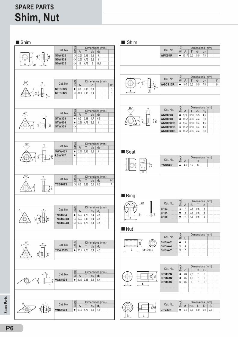
A B T dER03 m 7 2,6 0,6 3ER04 l 9 3,5 0,6 4ER05 l 11 4,3 0,6 5
Repu
esto
sPiezas de repuestoPasadores, Tuercas, Excéntricas
P6
A T d1 d2STW323 l 9,5 3,18 4,7 6,5STW434 l 12,65 4,76 6,2 8STW333 m
A T d1 d2SWW433 l 12,65 5,15 6,2 8LSW317 l
A T d1 d2 θ°TCS16T3 q 8,8 2,38 5,3 6,3 7
A T d1 d2TNS1604 l 9,45 4,76 3,4 4,5TNS1603B m 9,45 3,18 3,4 4,5TNS1604B m 9,45 4,76 3,4 4,5
A T d1 d2TRW5505 l 10,5 4,76 3,4 4,5
A T d1 d2VCS1604 l 8,25 3,18 5,3 6,4
A T d1 d2VNS1604 l 9,45 4,76 3,4 4,5
A T d1 d2WFXS4R l 10,17 3,0 5,5 7,5
A T d1 d2 θ°WGCS13R l 10,7 3,0 5,5 7,5 5
A T d1 d2WNS0604 l 9,52 3,18 3,5 4,5WNS0804 l 12,57 4,76 4,4 6,3WNS0603B q 9,27 3,18 3,4 4,5WNS0803B m 12,57 3,18 3,4 4,5WNS0804B m 12,57 4,76 4,4 6,0
LBNBW-2 l 3BNBW-4 m 4BNBW-7 q 7
d L D BCPM32N l M4 7,5 7 3CPM43N l M5 8,5 7 3CPM43S m M5 6 7 3
d L D BCPV33N l M4 0,5 6,0 6,0 2,5
A T d1 d2SSW423 q 12,65 3,18 6,2 8SSW433 m 12,65 4,76 6,2 8SSW635 m 19 4,76 9 11,5
A T d θ°STPD322 l 8,4 3,18 3,4 6STPD422 m 11,0 3,18 3,4 6
θ°
60°
A
Ød 1
T
A Ød 1
T
LB
ød DØ
ød1
ød2
T60゚
A
ød1
ød2
TA
60゚
A
ød1
ød2
T
B TA
ød
d L HPWSS4R p 4,6 15 8
ød
L
H
Spar
e Par
tsSPARE PARTS
Cat. No.Dimensions (mm)
Stoc
k
Shim
Cat. No.Dimensions (mm)
Stoc
k
Cat. No.Dimensions (mm)
Stoc
k
Cat. No.Dimensions (mm)
Stoc
k
Cat. No.Dimensions (mm)
Stoc
k
Cat. No.Dimensions (mm)
Stoc
k
Cat. No.Dimensions (mm)
Stoc
k
Cat. No.Dimensions (mm)
Stoc
k
Shim
Cat. No.Dimensions (mm)
Stoc
k
Cat. No.Dimensions (mm)
Stoc
k
Shim, Nut
Cat. No.Dimensions (mm)
Stoc
k
Nut
Cat. No.Dimensions (mm)
Stoc
k
Cat. No.Dimensions (mm)
Stoc
k
Cat. No.Dimensions (mm)
Stoc
k
Cat. No.Dimensions (mm)
Stoc
k
Pitch
RingCat. No.
Dimensions (mm)
Stoc
k
SeatCat. No.
Dimensions (mm)
Stoc
k
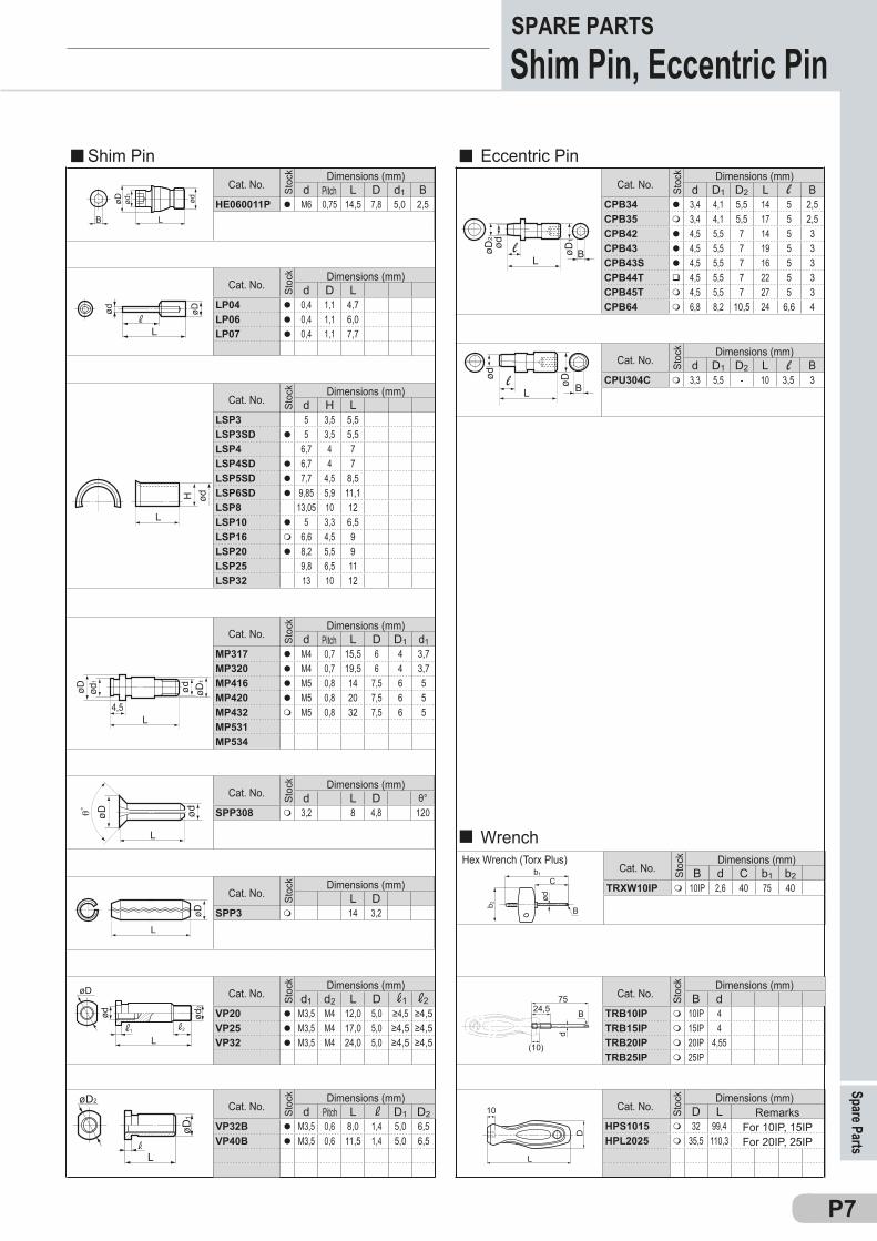
D LHPS1015 m 32 99,4HPL2025 m 35,5 110,3
B d C b1 b2TRXW10IP m 10IP 2,6 40 75 40
ød
b1
C
b 2 B
RepuestosPiezas de repuestoLlaves
P7
d L D d1 BHE060011P l M6 0,75 14,5 7,8 5,0 2,5
d D LLP04 l 0,4 1,1 4,7LP06 l 0,4 1,1 6,0LP07 l 0,4 1,1 7,7
d H LLSP3 5 3,5 5,5LSP3SD l 5 3,5 5,5LSP4 6,7 4 7LSP4SD l 6,7 4 7LSP5SD l 7,7 4,5 8,5LSP6SD l 9,85 5,9 11,1LSP8 13,05 10 12LSP10 l 5 3,3 6,5LSP16 m 6,6 4,5 9LSP20 l 8,2 5,5 9LSP25 9,8 6,5 11LSP32 13 10 12
d L D D1 d1MP317 l M4 0,7 15,5 6 4 3,7MP320 l M4 0,7 19,5 6 4 3,7MP416 l M5 0,8 14 7,5 6 5MP420 l M5 0,8 20 7,5 6 5MP432 m M5 0,8 32 7,5 6 5MP531MP534
d L D θ°SPP308 m 3,2 8 4,8 120
L DSPP3 m 14 3,2
d1 d2 L DVP20 l M3,5 M4 12,0 5,0 ≥4,5 ≥4,5VP25 l M3,5 M4 17,0 5,0 ≥4,5 ≥4,5VP32 l M3,5 M4 24,0 5,0 ≥4,5 ≥4,5
d D1 D2 L BCPB34 l 3,4 4,1 5,5 14 5 2,5CPB35 m 3,4 4,1 5,5 17 5 2,5CPB42 l 4,5 5,5 7 14 5 3CPB43 l 4,5 5,5 7 19 5 3CPB43S l 4,5 5,5 7 16 5 3CPB44T q 4,5 5,5 7 22 5 3CPB45T m 4,5 5,5 7 27 5 3CPB64 m 6,8 8,2 10,5 24 6,6 4
d D1 D2 L BCPU304C m 3,3 5,5 - 10 3,5 3
L
ød øDødød
1
øD
LB
d L D1 D2VP32B l M3,5 0,6 8,0 1,4 5,0 6,5VP40B l M3,5 0,6 11,5 1,4 5,0 6,5
L
øD1
øD2
1 2
L
ød2
ød
øD
1 2
B dTRB10IP m 10IP 4TRB15IP m 15IP 4TRB20IP m 20IP 4,55TRB25IP m 25IP
75
d
B24,5
(10)
D
L
10
Spare PartsSPARE PARTSShim Pin, Eccentric Pin
Cat. No.Dimensions (mm)
Stoc
k
Pitch
Shim Pin
Cat. No.Dimensions (mm)
Stoc
kCat. No.
Dimensions (mm) St
ock
Cat. No.Dimensions (mm)
Stoc
k
Cat. No.Dimensions (mm)
Stoc
k
Cat. No.Dimensions (mm)
Stoc
k
Cat. No.Dimensions (mm)
Stoc
k
Eccentric PinCat. No.
Dimensions (mm)
Stoc
k
Cat. No.Dimensions (mm)
Stoc
k
Pitch
PitchCat. No.Dimensions (mm)
Stoc
k
Hex Wrench (Torx Plus)Cat. No.
Dimensions (mm)
Stoc
k
Wrench
Cat. No.Dimensions (mm)
Stoc
k
Cat. No.Dimensions (mm)
Stoc
k
RemarksFor 10IP, 15IPFor 20IP, 25IP
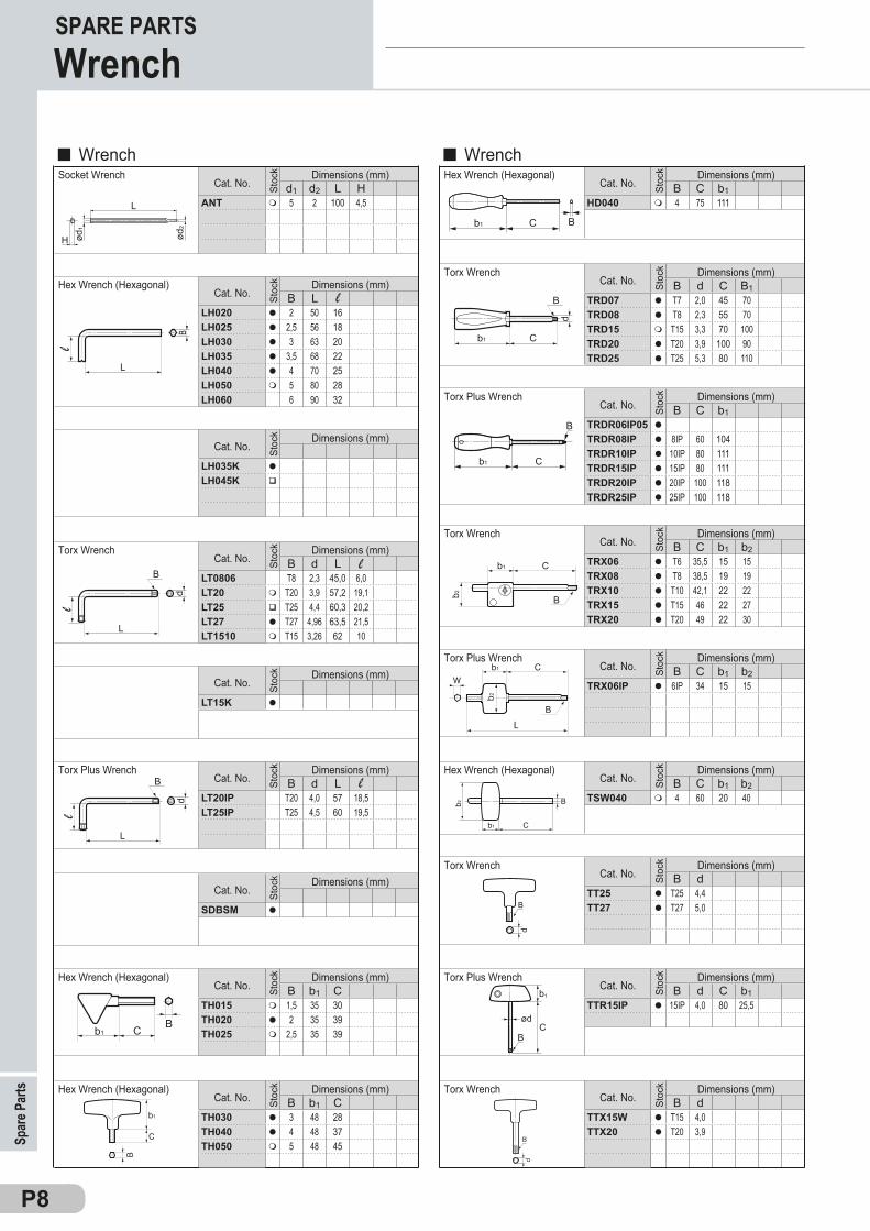
B C b1HD040 m 4 75 111
P8P8
LT15K l
d1 d2 L HANT m 5 2 100 4,5
LH035K l
LH045K q
SDBSM l
B LLH020 l 2 50 16LH025 l 2,5 56 18LH030 l 3 63 20LH035 l 3,5 68 22LH040 l 4 70 25LH050 m 5 80 28LH060 6 90 32
B d LLT0806 T8 2,3 45,0 6,0LT20 m T20 3,9 57,2 19,1LT25 q T25 4,4 60,3 20,2LT27 l T27 4,96 63,5 21,5LT1510 m T15 3,26 62 10
B d LLT20IP T20 4,0 57 18,5LT25IP T25 4,5 60 19,5
B b1 CTH015 m 1,5 35 30TH020 l 2 35 39TH025 m 2,5 35 39
B b1 CTH030 l 3 48 28TH040 l 4 48 37TH050 m 5 48 45
B d C B1TRD07 l T7 2,0 45 70TRD08 l T8 2,3 55 70TRD15 m T15 3,3 70 100TRD20 l T20 3,9 100 90TRD25 l T25 5,3 80 110
B C b1TRDR06IP05 l
TRDR08IP l 8IP 60 104TRDR10IP l 10IP 80 111TRDR15IP l 15IP 80 111TRDR20IP l 20IP 100 118TRDR25IP l 25IP 100 118
B C b1 b2TRX06 l T6 35,5 15 15TRX08 l T8 38,5 19 19TRX10 l T10 42,1 22 22TRX15 l T15 46 22 27TRX20 l T20 49 22 30
B C b1 b2TRX06IP l 6IP 34 15 15
B d C b1TTR15IP l 15IP 4,0 80 25,5
B dTTX15W l T15 4,0TTX20 l T20 3,9
B dTT25 l T25 4,4TT27 l T27 5,0
B C b1 b2TSW040 m 4 60 20 40
b2
b1 C
B
b1
C
ød2
H
L
ød1
Socket Wrench
SPARE PARTSWrench
Spar
e Par
ts
WrenchWrench
Hex Wrench (Hexagonal)
Hex Wrench (Hexagonal)
Hex Wrench (Hexagonal)
Hex Wrench (Hexagonal)
Hex Wrench (Hexagonal)
Torx Wrench
Torx Wrench
Torx Wrench
Torx Wrench
Torx Wrench
Torx Plus Wrench
Torx Plus Wrench
Torx Plus Wrench
Torx Plus Wrench
Cat. No.Dimensions (mm)
Stoc
k
Cat. No.Dimensions (mm)
Stoc
k
Cat. No.Dimensions (mm)
Stoc
k
Cat. No.Dimensions (mm)
Stoc
k
Cat. No.Dimensions (mm)
Stoc
k
Cat. No.Dimensions (mm)
Stoc
k
Cat. No.Dimensions (mm)
Stoc
k
Cat. No.Dimensions (mm)
Stoc
k
Cat. No.Dimensions (mm)
Stoc
k Cat. No.Dimensions (mm)
Stoc
k
Cat. No.Dimensions (mm)
Stoc
k
Cat. No.Dimensions (mm)
Stoc
k
Cat. No.Dimensions (mm)
Stoc
k Cat. No.Dimensions (mm)
Stoc
k
Cat. No.Dimensions (mm)
Stoc
k
Cat. No.Dimensions (mm)
Stoc
k
Cat. No.Dimensions (mm)
Stoc
k
Cat. No.Dimensions (mm)
Stoc
k

P9–P21P
P9
IndexIndex
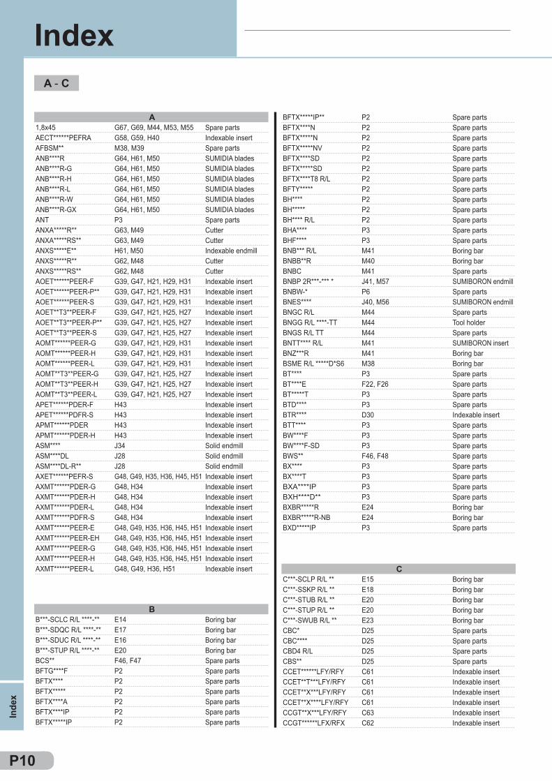
A1,8x45 G67, G69, M44, M53, M55AECT******PEFRA G58, G59, H40AFBSM** M38, M39ANB****R G64, H61, M50ANB****R-G G64, H61, M50ANB****R-H G64, H61, M50ANB****R-L G64, H61, M50ANB****R-W G64, H61, M50ANB****R-GX G64, H61, M50ANT P3ANXA*****R** G63, M49ANXA*****RS** G63, M49ANXS*****E** H61, M50ANXS*****R** G62, M48ANXS*****RS** G62, M48AOET******PEER-F G39, G47, H21, H29, H31AOET******PEER-P** G39, G47, H21, H29, H31AOET******PEER-S G39, G47, H21, H29, H31AOET**T3**PEER-F G39, G47, H21, H25, H27AOET**T3**PEER-P** G39, G47, H21, H25, H27AOET**T3**PEER-S G39, G47, H21, H25, H27AOMT******PEER-G G39, G47, H21, H29, H31AOMT******PEER-H G39, G47, H21, H29, H31AOMT******PEER-L G39, G47, H21, H29, H31AOMT**T3**PEER-G G39, G47, H21, H25, H27AOMT**T3**PEER-H G39, G47, H21, H25, H27AOMT**T3**PEER-L G39, G47, H21, H25, H27APET******PDER-F H43APET******PDFR-S H43APMT******PDER H43APMT******PDER-H H43ASM**** J34ASM****DL J28ASM****DL-R** J28AXET******PEFR-S G48, G49, H35, H36, H45, H51AXMT******PDER-G G48, H34AXMT******PDER-H G48, H34AXMT******PDER-L G48, H34AXMT******PDFR-S G48, H34AXMT******PEER-E G48, G49, H35, H36, H45, H51AXMT******PEER-EH G48, G49, H35, H36, H45, H51AXMT******PEER-G G48, G49, H35, H36, H45, H51AXMT******PEER-H G48, G49, H35, H36, H45, H51AXMT******PEER-L G48, G49, H36, H51
BFTX*****IP** P2BFTX****N P2BFTX*****N P2BFTX*****NV P2BFTX****SD P2BFTX*****SD P2BFTX****T8 R/L P2BFTY***** P2BH**** P2BH***** P2BH**** R/L P2BHA**** P3BHF**** P3BNB*** R/L M41BNBB**R M40BNBC M41BNBP 2R***-*** * J41, M57BNBW-* P6BNES**** J40, M56BNGC R/L M44BNGG R/L ****-TT M44BNGS R/L TT M44BNTT**** R/L M41BNZ***R M41BSME R/L *****D*S6 M38BT**** P3BT****E F22, F26BT*****T P3BTD**** P3BTR**** D30BTT**** P3BW****F P3BW****F-SD P3BWS** F46, F48BX**** P3BX****T P3BXA****IP P3BXH****D** P3BXBR*****R E24BXBR*****R-NB E24BXD*****IP P3
BB***-SCLC R/L ****-** E14B***-SDQC R/L ****-** E17B***-SDUC R/L ****-** E16B***-STUP R/L ****-** E20BCS** F46, F47BFTG****F P2BFTX**** P2BFTX***** P2BFTX****A P2BFTX****IP P2BFTX*****IP P2
CC***-SCLP R/L ** E15C***-SSKP R/L ** E18C***-STUB R/L ** E20C***-STUP R/L ** E20C***-SWUB R/L ** E23CBC* D25CBC**** D25CBD4 R/L D25CBS** D25CCET******LFY/RFY C61CCET**T***LFY/RFY C61CCET**X***LFY/RFY C61CCET**X****LFY/RFY C61CCGT**X***LFY/RFY C63CCGT******LFX/RFX C62
P10
A - C
Inde
x
Index
Spare partsIndexable insertSpare partsSUMIDIA bladesSUMIDIA bladesSUMIDIA bladesSUMIDIA bladesSUMIDIA bladesSUMIDIA bladesSpare partsCutterCutterIndexable endmillCutterCutterIndexable insertIndexable insertIndexable insertIndexable insertIndexable insertIndexable insertIndexable insertIndexable insertIndexable insertIndexable insertIndexable insertIndexable insertIndexable insertIndexable insertIndexable insertIndexable insertSolid endmillSolid endmillSolid endmillIndexable insertIndexable insertIndexable insertIndexable insertIndexable insertIndexable insertIndexable insertIndexable insertIndexable insertIndexable insert
Spare partsSpare partsSpare partsSpare partsSpare partsSpare partsSpare partsSpare partsSpare partsSpare partsSpare partsSpare partsSpare partsBoring barBoring barSpare partsSUMIBORON endmillSpare partsSUMIBORON endmillSpare partsTool holderSpare partsSUMIBORON insertBoring barBoring barSpare partsSpare partsSpare partsSpare partsIndexable insertSpare partsSpare partsSpare partsSpare partsSpare partsSpare partsSpare partsSpare partsBoring barBoring barSpare parts
Boring barBoring barBoring barBoring barSpare partsSpare partsSpare partsSpare partsSpare partsSpare partsSpare parts
Boring barBoring barBoring barBoring barBoring barSpare partsSpare partsSpare partsSpare partsIndexable insertIndexable insertIndexable insertIndexable insertIndexable insertIndexable insert

CCGT*******LFX/RFX C62CCGT**T***LFX/RFX C62CCGT**T****LFX/RFX C62CCGT**X***LFYS/RFYS C62CCGT**X****LFYS/RFYS C62CCGT******M NFC C62CCGT******M NSC C63CCGT******M NSI C63CCGT******NAG C63CCGT******NFV NC2 M4CCGT******NFV NU2 M6CCGT******NLV NC2 M4CCGT******NLV NU2 M6CCGT******NSC C63CCGW**T*** M7CCGW******HS-NC2 M4CCGW******HS-NU2 M6CCGW******LE-NC2 M4CCGW******LF-NU2 M6CCGW******LS-NC2 M4CCGW******LT-NC2 M4CCGW******NC-2 M4CCGW******NC-W2 M4CCGW******NC-WG2 M4CCGW******NC-WH2 M4CCGW******NS M7CCGW******NU M7CCGW******NU-2 M6CCGW******NU-WG2 M6CCGW******NU-WH2 M6CCH*** G53, H9, H10CCLN R/L ****-*** D25CCM 6B L/R F40CCM 8 LONG D25, D26CCM 8 UL D25, F40CCM 8 UR F40CCMT****** M8CCMT******L/R-DM NU M8CCMT******NF M8CCMT******NFB C64CCMT******NFP C64CCMT******NGD NF M8CCMT******NLD NF M8CCMT******NLB C64CCMT******NLU C64CCMT******NLU-W C64CCMT******NMU C65CCMT******NSC C65CCMT******NSK C65CCMT******NSU C64CCMT**T***NUS C65CCMW****** C65CCMW******RH M33CCMW**T*** C65CCS**T* P5CGA R/L **** *** M43CNGA****** C26CNGA******ES-NC4 M9CNGA******HS-NC2 M9CNGA******HS-NU2 M10
CNGA******LE-NC2 M9CNGA******LF-NU2 M10CNGA******LS-NC2 M9CNGA******LT-NC2 M9CNGA******NC-4 M9CNGA******NC-W4 M9CNGA******NC-WG4 M9CNGA******NC-WH4 M9CNGA******NS-2 M10CNGA******NU-2 M10CNGA******NU-W2 M10CNGA******NU-WG2 M10CNGA******NU-WH2 M10CNGG******NEF C26CNGG******NFV NC4 M9CNGG******NLV NC4 M9CNGG******NSV NC4 M9CNGG******NGH C26CNGG******NSU C26CNGM******NLV NU2 M10CNGN****** M11CNGX****** M11CNMA****** C26CNMA****** M11CNMA******NS M11CNMA******NU M11CNMA******NU-W M11CNMG******NEF C18CNMG******NEG C20CNMG******NEM C21CNMG******NEX C20CNMG******NFA C18CNMG******NFB C18CNMG******NFE C18CNMG******NFL C18CNMG******NGE C20CNMG******NGU C19CNMG******NGU-W C19CNMG******NGZ C23CNMG******NLU C18CNMG******NLU-W C18CNMG******NME C21CNMG******NMU C21CNMG******NMX C22CNMG******NSE C19CNMG******NSE-W C19CNMG******NSU C19CNMG******NSX C19CNMG******NUG C20CNMG******NUP C21CNMG******NUX C22CNMG******NUZ C23CNMM******NHF C24CNMM******NHG C24CNMM******NHP C24CNMM******NHU C25CNMM******NHW C25CNMM******NMH C24CNMM******NMP C24CNMQ******N G52
P11
C - C
Index
Index
Indexable insertIndexable insertIndexable insertIndexable insertIndexable insertIndexable insertIndexable insertIndexable insertIndexable insertSUMIBORON insertSUMIBORON insertSUMIBORON insertSUMIBORON insertIndexable insertSUMIBORON insertSUMIBORON insertSUMIBORON insertSUMIBORON insertSUMIBORON insertSUMIBORON insertSUMIBORON insertSUMIBORON insertSUMIBORON insertSUMIBORON insertSUMIBORON insertSUMIBORON insertSUMIBORON insertSUMIBORON insertSUMIBORON insertSUMIBORON insertSpare partsTool holderSpare partsSpare partsSpare partsSpare partsSUMIDIA insertSUMIDIA insertSUMIDIA insertIndexable insertIndexable insertSUMIDIA insertSUMIDIA insertIndexable insertIndexable insertIndexable insertIndexable insertIndexable insertIndexable insertIndexable insertIndexable insertIndexable insertSUMIDIA insertIndexable insertSpare partsSUMIBORON insertIndexable insertSUMIBORON insertSUMIBORON insertSUMIBORON insert
SUMIBORON insertSUMIBORON insertSUMIBORON insertSUMIBORON insertSUMIBORON insertSUMIBORON insertSUMIBORON insertSUMIBORON insertSUMIBORON insertSUMIBORON insertSUMIBORON insertSUMIBORON insertSUMIBORON insertIndexable insertSUMIBORON insertSUMIBORON insertSUMIBORON insertIndexable insertIndexable insertSUMIBORON insertSUMIBORON insertSUMIBORON insertIndexable insertSUMIBORON insertSUMIBORON insertSUMIBORON insertSUMIBORON insertIndexable insertIndexable insertIndexable insertIndexable insertIndexable insertIndexable insertIndexable insertIndexable insertIndexable insertIndexable insertIndexable insertIndexable insertIndexable insertIndexable insertIndexable insertIndexable insertIndexable insertIndexable insertIndexable insertIndexable insertIndexable insertIndexable insertIndexable insertIndexable insertIndexable insertIndexable insertIndexable insertIndexable insertIndexable insertIndexable insertIndexable insertIndexable insertIndexable insert
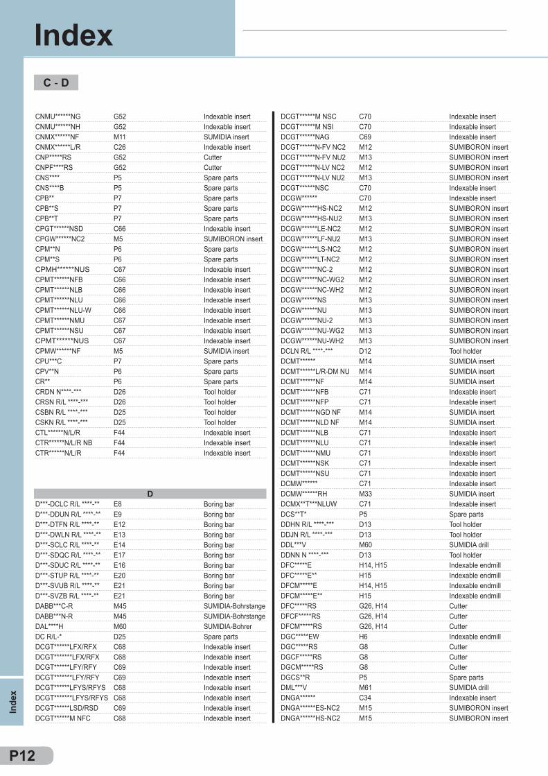
CNMU******NG G52CNMU******NH G52CNMX******NF M11CNMX******L/R C26CNP*****RS G52CNPF****RS G52CNS**** P5CNS****B P5CPB** P7CPB**S P7CPB**T P7CPGT******NSD C66CPGW******NC2 M5CPM**N P6CPM**S P6CPMH******NUS C67CPMT******NFB C66CPMT******NLB C66CPMT******NLU C66CPMT******NLU-W C66CPMT******NMU C67CPMT******NSU C67CPMT******NUS C67CPMW******NF M5CPU***C P7CPV**N P6CR** P6CRDN N****-*** D26CRSN R/L ****-*** D26CSBN R/L ****-*** D25CSKN R/L ****-*** D25CTL******N/L/R F44CTR******N/L/R NB F44CTR******N/L/R F44
DCGT******M NSC C70DCGT******M NSI C70DCGT******NAG C69DCGT******N-FV NC2 M12DCGT******N-FV NU2 M13DCGT******N-LV NC2 M12DCGT******N-LV NU2 M13DCGT******NSC C70DCGW****** C70DCGW******HS-NC2 M12DCGW******HS-NU2 M13DCGW******LE-NC2 M12DCGW******LF-NU2 M13DCGW******LS-NC2 M12DCGW******LT-NC2 M12DCGW******NC-2 M12DCGW******NC-WG2 M12DCGW******NC-WH2 M12DCGW******NS M13DCGW******NU M13DCGW******NU-2 M13DCGW******NU-WG2 M13DCGW******NU-WH2 M13DCLN R/L ****-*** D12DCMT****** M14DCMT******L/R-DM NU M14DCMT******NF M14DCMT******NFB C71DCMT******NFP C71DCMT******NGD NF M14DCMT******NLD NF M14DCMT******NLB C71DCMT******NLU C71DCMT******NMU C71DCMT******NSK C71DCMT******NSU C71DCMW****** C71DCMW******RH M33DCMX**T***NLUW C71DCS**T* P5DDHN R/L ****-*** D13DDJN R/L ****-*** D13DDL***V M60DDNN N ****-*** D13DFC*****E H14, H15DFC*****E** H15DFCM*****E H14, H15DFCM*****E** H15DFC*****RS G26, H14DFCF*****RS G26, H14DFCM*****RS G26, H14DGC*****EW H6DGC*****RS G8DGCF*****RS G8DGCM*****RS G8DGCS**R P5DML***V M61DNGA****** C34DNGA******ES-NC2 M15DNGA******HS-NC2 M15
DD***-DCLC R/L ****-** E8D***-DDUN R/L ****-** E9D***-DTFN R/L ****-** E12D***-DWLN R/L ****-** E13D***-SCLC R/L ****-** E14D***-SDQC R/L ****-** E17D***-SDUC R/L ****-** E16D***-STUP R/L ****-** E20D***-SVUB R/L ****-** E21D***-SVZB R/L ****-** E21DABB***C-R M45DABB***N-R M45DAL****H M60DC R/L-* D25DCGT******LFX/RFX C68DCGT*******LFX/RFX C68DCGT******LFY/RFY C69DCGT*******LFY/RFY C69DCGT******LFYS/RFYS C68DCGT*******LFYS/RFYS C68DCGT******LSD/RSD C69DCGT******M NFC C68
P12
C - D
Inde
x
Index
Indexable insertIndexable insertSUMIDIA insertIndexable insertCutterCutterSpare partsSpare partsSpare partsSpare partsSpare partsIndexable insertSUMIBORON insertSpare partsSpare partsIndexable insertIndexable insertIndexable insertIndexable insertIndexable insertIndexable insertIndexable insertIndexable insertSUMIDIA insertSpare partsSpare partsSpare partsTool holderTool holderTool holderTool holderIndexable insertIndexable insertIndexable insert
Indexable insertIndexable insertIndexable insertSUMIBORON insertSUMIBORON insertSUMIBORON insertSUMIBORON insertIndexable insertIndexable insertSUMIBORON insertSUMIBORON insertSUMIBORON insertSUMIBORON insertSUMIBORON insertSUMIBORON insertSUMIBORON insertSUMIBORON insertSUMIBORON insertSUMIBORON insertSUMIBORON insertSUMIBORON insertSUMIBORON insertSUMIBORON insertTool holderSUMIDIA insertSUMIDIA insertSUMIDIA insertIndexable insertIndexable insertSUMIDIA insertSUMIDIA insertIndexable insertIndexable insertIndexable insertIndexable insertIndexable insertIndexable insertSUMIDIA insertIndexable insertSpare partsTool holderTool holderSUMIDIA drillTool holderIndexable endmillIndexable endmillIndexable endmillIndexable endmillCutterCutterCutterIndexable endmillCutterCutterCutterSpare partsSUMIDIA drillIndexable insertSUMIBORON insertSUMIBORON insert
Boring barBoring barBoring barBoring barBoring barBoring barBoring barBoring barBoring barBoring barSUMIDIA-BohrstangeSUMIDIA-BohrstangeSUMIDIA-BohrerSpare partsIndexable insertIndexable insertIndexable insertIndexable insertIndexable insertIndexable insertIndexable insertIndexable insert
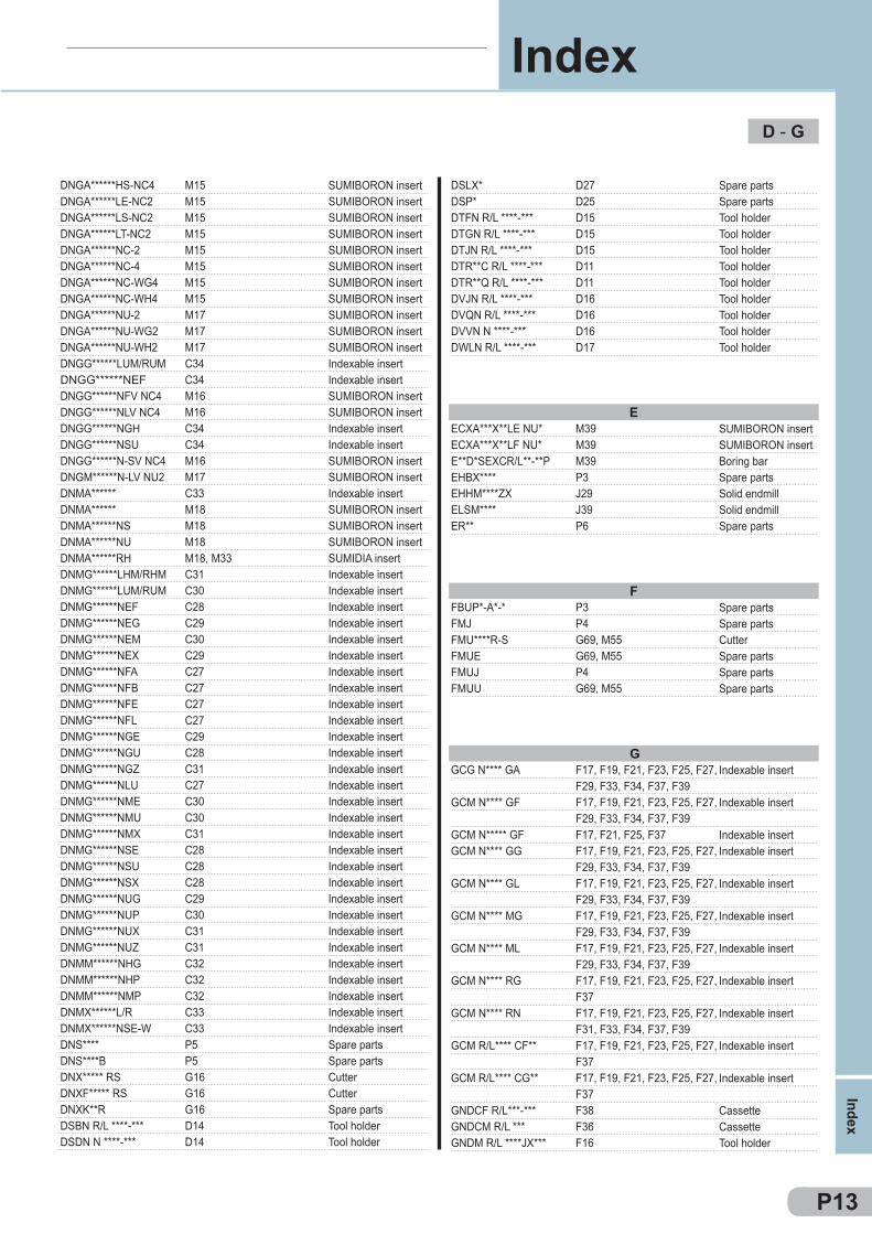
DNGA******HS-NC4 M15DNGA******LE-NC2 M15DNGA******LS-NC2 M15DNGA******LT-NC2 M15DNGA******NC-2 M15DNGA******NC-4 M15DNGA******NC-WG4 M15DNGA******NC-WH4 M15DNGA******NU-2 M17DNGA******NU-WG2 M17DNGA******NU-WH2 M17DNGG******LUM/RUM C34DNGG******NEF C34DNGG******NFV NC4 M16DNGG******NLV NC4 M16DNGG******NGH C34DNGG******NSU C34DNGG******N-SV NC4 M16DNGM******N-LV NU2 M17DNMA****** C33DNMA****** M18DNMA******NS M18DNMA******NU M18DNMA******RH M18, M33DNMG******LHM/RHM C31DNMG******LUM/RUM C30DNMG******NEF C28DNMG******NEG C29DNMG******NEM C30DNMG******NEX C29DNMG******NFA C27DNMG******NFB C27DNMG******NFE C27DNMG******NFL C27DNMG******NGE C29DNMG******NGU C28DNMG******NGZ C31DNMG******NLU C27DNMG******NME C30DNMG******NMU C30DNMG******NMX C31DNMG******NSE C28DNMG******NSU C28DNMG******NSX C28DNMG******NUG C29DNMG******NUP C30DNMG******NUX C31DNMG******NUZ C31DNMM******NHG C32DNMM******NHP C32DNMM******NMP C32DNMX******L/R C33DNMX******NSE-W C33DNS**** P5DNS****B P5DNX***** RS G16DNXF***** RS G16DNXK**R G16DSBN R/L ****-*** D14DSDN N ****-*** D14
DSLX* D27DSP* D25DTFN R/L ****-*** D15DTGN R/L ****-*** D15DTJN R/L ****-*** D15DTR**C R/L ****-*** D11DTR**Q R/L ****-*** D11DVJN R/L ****-*** D16DVQN R/L ****-*** D16DVVN N ****-*** D16DWLN R/L ****-*** D17
EECXA***X**LE NU* M39ECXA***X**LF NU* M39E**D*SEXCR/L**-**P M39EHBX**** P3EHHM****ZX J29ELSM**** J39ER** P6
FFBUP*-A*-* P3FMJ P4FMU****R-S G69, M55FMUE G69, M55FMUJ P4FMUU G69, M55
GGCG N**** GA F17, F19, F21, F23, F25, F27,
F29, F33, F34, F37, F39GCM N**** GF F17, F19, F21, F23, F25, F27,
F29, F33, F34, F37, F39GCM N***** GF F17, F21, F25, F37GCM N**** GG F17, F19, F21, F23, F25, F27,
F29, F33, F34, F37, F39GCM N**** GL F17, F19, F21, F23, F25, F27,
F29, F33, F34, F37, F39GCM N**** MG F17, F19, F21, F23, F25, F27,
F29, F33, F34, F37, F39GCM N**** ML F17, F19, F21, F23, F25, F27,
F29, F33, F34, F37, F39GCM N**** RG F17, F19, F21, F23, F25, F27,
F37GCM N**** RN F17, F19, F21, F23, F25, F27,
F31, F33, F34, F37, F39GCM R/L**** CF** F17, F19, F21, F23, F25, F27,
F37GCM R/L**** CG** F17, F19, F21, F23, F25, F27,
F37GNDCF R/L***-*** F38GNDCM R/L *** F36GNDM R/L ****JX*** F16
P13
D - G
Index
Index
SUMIBORON insertSUMIBORON insertSUMIBORON insertSUMIBORON insertSUMIBORON insertSUMIBORON insertSUMIBORON insertSUMIBORON insertSUMIBORON insertSUMIBORON insertSUMIBORON insertIndexable insertIndexable insertSUMIBORON insertSUMIBORON insertIndexable insertIndexable insertSUMIBORON insertSUMIBORON insertIndexable insertSUMIBORON insertSUMIBORON insertSUMIBORON insertSUMIDIA insertIndexable insertIndexable insertIndexable insertIndexable insertIndexable insertIndexable insertIndexable insertIndexable insertIndexable insertIndexable insertIndexable insertIndexable insertIndexable insertIndexable insertIndexable insertIndexable insertIndexable insertIndexable insertIndexable insertIndexable insertIndexable insertIndexable insertIndexable insertIndexable insertIndexable insertIndexable insertIndexable insertIndexable insertIndexable insertSpare partsSpare partsCutterCutterSpare partsTool holderTool holder
Spare partsSpare partsTool holderTool holderTool holderTool holderTool holderTool holderTool holderTool holderTool holder
SUMIBORON insertSUMIBORON insertBoring barSpare partsSolid endmillSolid endmillSpare parts
Spare partsSpare partsCutterSpare partsSpare partsSpare parts
Indexable insert
Indexable insert
Indexable insertIndexable insert
Indexable insert
Indexable insert
Indexable insert
Indexable insert
Indexable insert
Indexable insert
Indexable insert
CassetteCassetteTool holder
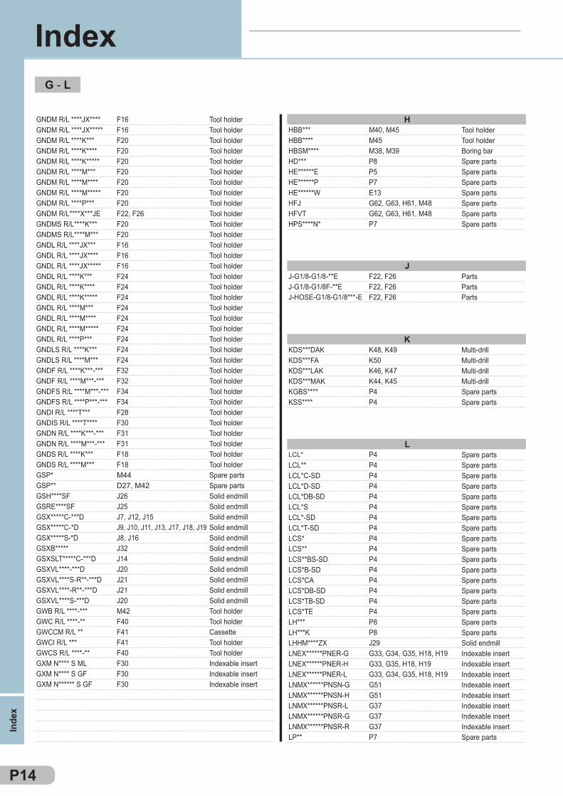
GNDM R/L ****JX**** F16GNDM R/L ****JX***** F16GNDM R/L ****K*** F20GNDM R/L ****K**** F20GNDM R/L ****K***** F20GNDM R/L ****M*** F20GNDM R/L ****M**** F20GNDM R/L ****M***** F20GNDM R/L ****P*** F20GNDM R/L****X***JE F22, F26GNDMS R/L****K*** F20GNDMS R/L****M*** F20GNDL R/L ****JX*** F16GNDL R/L ****JX**** F16GNDL R/L ****JX***** F16GNDL R/L ****K*** F24GNDL R/L ****K**** F24GNDL R/L ****K***** F24GNDL R/L ****M*** F24GNDL R/L ****M**** F24GNDL R/L ****M***** F24GNDL R/L ****P*** F24GNDLS R/L ****K*** F24GNDLS R/L ****M*** F24GNDF R/L ****K***-*** F32GNDF R/L ****M***-*** F32GNDFS R/L ****M***-*** F34GNDFS R/L ****P***-*** F34GNDI R/L ****T*** F28GNDIS R/L ****T**** F30GNDN R/L ****K***-*** F31GNDN R/L ****M***-*** F31GNDS R/L ****K*** F18GNDS R/L ****M*** F18GSP* M44GSP** D27, M42GSH****SF J26GSRE****SF J25GSX*****C-***D J7, J12, J15GSX*****C-*D J9, J10, J11, J13, J17, J18, J19GSX*****S-*D J8, J16GSXB***** J32GSXSLT*****C-***D J14GSXVL****-***D J20GSXVL****S-R**-***D J21GSXVL****-R**-***D J21GSXVL****S-***D J20GWB R/L ****-*** M42GWC R/L ****-** F40GWCCM R/L ** F41GWCI R/L *** F41GWCS R/L ****-** F40GXM N**** S ML F30GXM N**** S GF F30GXM N****** S GF F30
HHBB*** M40, M45HBB**** M45HBSM**** M38, M39HD*** P8HE******E P5HE******P P7HE******W E13HFJ G62, G63, H61, M48HFVT G62, G63, H61, M48HPS****N* P7
JJ-G1/8-G1/8-**E F22, F26J-G1/8-G1/8F-**E F22, F26J-HOSE-G1/8-G1/8***-E F22, F26
KKDS***DAK K48, K49KDS***FA K50KDS***LAK K46, K47KDS***MAK K44, K45KGBS**** P4KSS**** P4
LLCL* P4LCL** P4LCL*C-SD P4LCL*D-SD P4LCL*DB-SD P4LCL*S P4LCL*-SD P4LCL*T-SD P4LCS* P4LCS** P4LCS**BS-SD P4LCS*B-SD P4LCS*CA P4LCS*DB-SD P4LCS*TB-SD P4LCS*TE P4LH*** P8LH***K P8LHHM****ZX J29LNEX******PNER-G G33, G34, G35, H18, H19LNEX******PNER-H G33, G35, H18, H19LNEX******PNER-L G33, G34, G35, H18, H19LNMX******PNSN-G G51LNMX******PNSN-H G51LNMX******PNSR-L G37LNMX******PNSR-G G37LNMX******PNSR-R G37LP** P7
P14
G - L
Inde
x
Index
Tool holderTool holderTool holderTool holderTool holderTool holderTool holderTool holderTool holderTool holderTool holderTool holderTool holderTool holderTool holderTool holderTool holderTool holderTool holderTool holderTool holderTool holderTool holderTool holderTool holderTool holderTool holderTool holderTool holderTool holderTool holderTool holderTool holderTool holderSpare partsSpare partsSolid endmillSolid endmillSolid endmillSolid endmillSolid endmillSolid endmillSolid endmillSolid endmillSolid endmillSolid endmillSolid endmillTool holderTool holderCassetteTool holderTool holderIndexable insertIndexable insertIndexable insert
Tool holderTool holderBoring barSpare partsSpare partsSpare partsSpare partsSpare partsSpare partsSpare parts
PartsPartsParts
Multi-drillMulti-drillMulti-drillMulti-drillSpare partsSpare parts
Spare partsSpare partsSpare partsSpare partsSpare partsSpare partsSpare partsSpare partsSpare partsSpare partsSpare partsSpare partsSpare partsSpare partsSpare partsSpare partsSpare partsSpare partsSolid endmillIndexable insertIndexable insertIndexable insertIndexable insertIndexable insertIndexable insertIndexable insertIndexable insertSpare parts
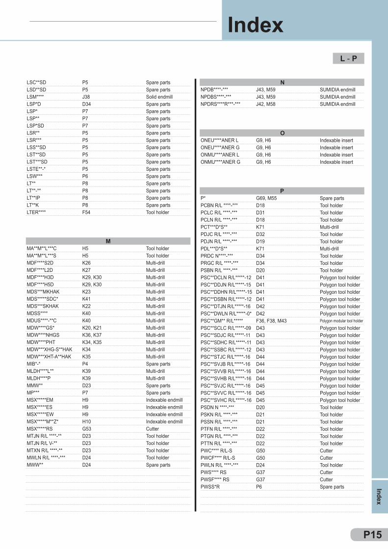
LSC**SD P5LSD**SD P5LSM**** J38LSP*D D34LSP* P7LSP** P7LSP*SD P7LSR** P5LSR*** P5LSS**SD P5LST**SD P5LST***SD P5LSTE**-* P5LSW*** P6LT** P8LT**-** P8LT**IP P8LT**K P8LTER**** F54
NNPDB****-*** J43, M59NPDBS****-*** J43, M59NPDRS****R***-*** J42, M58
MMA**M**L***C H5MA**M**L***S H5MDF****S2D K26MDF****L2D K27MDF****H3D K29, K30MDF****H5D K29, K30MDS***MKHAK K23MDS*****SDC* K41MDS***SKHAK K22MDSS**** K40MDUS****-**C K40MDW****GS* K20, K21MDW****NHGS K36, K37MDW****PHT K34, K35MDW***XHG-S**HAK K34MDW***XHT-A**HAK K35MIB*-* P4MLDH****L** K39MLDH****P K39MMW** D23MP*** P7MSX*****EM H9MSX*****ES H9MSX*****EW H9MSX*****M**Z* H10MSX*****RS G53MTJN R/L ****-** D23MTJN R/L V-** D23MTXN R/L ****-** D23MWLN R/L ****-*** D24MWW** D24
OONEU****ANER L G9, H6ONEU****ANER G G9, H6ONMU****ANER L G9, H6ONMU****ANER G G9, H6
PP* G69, M55PCBN R/L ****-*** D18PCLC R/L ****-*** D31PCLN R/L ****-*** D18PCT***D*S** K71PDJC R/L ****-*** D32PDJN R/L ****-*** D19PDL***D*S** K71PRDC N****-*** D34PRGC R/L ****-*** D34PSBN R/L ****-*** D20PSC**DCLN R/L*****-12 D41PSC**DDJN R/L*****-15 D41PSC**DDHN R/L*****-15 D41PSC**DSBN R/L*****-12 D41PSC**DTJN R/L*****-16 D42PSC**DWLN R/L*****-0* D42PSC**GM** R/L***** F36, F38, M43PSC**SCLC R/L*****-09 D43PSC**SDJC R/L*****-11 D43PSC**SDHC R/L*****-11 D43PSC**SSBC R/L*****-12 D43PSC**STJC R/L*****-16 D44PSC**SVJB R/L*****-16 D44PSC**SVVB R/L*****-16 D44PSC**SVHB R/L*****-16 D44PSC**SVJC R/L*****-16 D45PSC**SVVC R/L*****-16 D45PSC**SVHC R/L*****-16 D45PSDN N ****-*** D20PSKN R/L ****-*** D21PSSN R/L ****-*** D21PTFN R/L ****-*** D22PTGN R/L ****-*** D22PTTN R/L ****-*** D22PWC**** R/L-S G50PWCF**** R/L-S G50PWLN R/L ****-*** D24PWS**** RS G37PWSF**** RS G37PWSS*R P6
P15
L - P
Index
Index
Spare partsSpare partsSolid endmillSpare partsSpare partsSpare partsSpare partsSpare partsSpare partsSpare partsSpare partsSpare partsSpare partsSpare partsSpare partsSpare partsSpare partsSpare partsTool holder
SUMIDIA endmillSUMIDIA endmillSUMIDIA endmill
Tool holderTool holderMulti-drillMulti-drillMulti-drillMulti-drillMulti-drillMulti-drillMulti-drillMulti-drillMulti-drillMulti-drillMulti-drillMulti-drillMulti-drillMulti-drillSpare partsMulti-drillMulti-drillSpare partsSpare partsIndexable endmillIndexable endmillIndexable endmillIndexable endmillCutterTool holderTool holderTool holderTool holderSpare parts
Indexable insertIndexable insertIndexable insertIndexable insert
Spare partsTool holderTool holderTool holderMulti-drillTool holderTool holderMulti-drillTool holderTool holderTool holderPolygon tool holderPolygon tool holderPolygon tool holderPolygon tool holderPolygon tool holderPolygon tool holderPolygon modular tool holderPolygon tool holderPolygon tool holderPolygon tool holderPolygon tool holderPolygon tool holderPolygon tool holderPolygon tool holderPolygon tool holderPolygon tool holderPolygon tool holderPolygon tool holderTool holderTool holderTool holderTool holderTool holderTool holderCutterCutterTool holderCutterCutterSpare parts
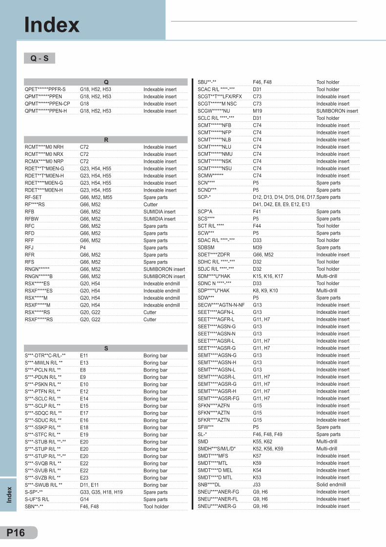
QQPET******PPFR-S G18, H52, H53QPMT******PPEN G18, H52, H53QPMT******PPEN-CP G18QPMT******PPEN-H G18, H52, H53
RRCMT****M0 NRH C72RCMT****M0 NRX C72RCMX****M0 NRP C72RDET**T*M0EN-G G23, H54, H55RDET**T*M0EN-H G23, H54, H55RDET****M0EN-G G23, H54, H55RDET****M0EN-H G23, H54, H55RF-SET G66, M52, M55RF****RS G66, M52RFB G66, M52RFBW G66, M52RFC G66, M52RFD G66, M52RFF G66, M52RFJ P4RFR G66, M52RFS G66, M52RNGN****** G66, M52RNGN******B G66, M52RSX*****ES G20, H54RSXF*****ES G20, H54RSX*****M G20, H54RSXF*****M G20, H54RSX*****RS G20, G22RSXF*****RS G20, G22
SS***-DTR**C-R/L-** E11S***-MWLN R/L ** E13S***-PCLN R/L ** E8S***-PDUN R/L ** E9S***-PSKN R/L ** E10S***-PTFN R/L ** E12S***-SCLC R/L ** E14S***-SCLP R/L ** E15S***-SDQC R/L ** E17S***-SDUC R/L ** E16S***-SSKP R/L ** E18S***-STFC R/L ** E19S***-STUB R/L **-** E20S***-STUP R/L ** E20S***-STUP R/L **-** E20S***-SVQB R/L ** E22S***-SVUB R/L ** E22S***-SVZB R/L ** E23S***-SWUB R/L ** D11, E11S-SP*-** G33, G35, H18, H19S-UF*S R/L G14SBN**-** F46, F48
SBU**-** F46, F48SCAC R/L ****-*** D31SCGT**T***LFX/RFX C73SCGT******M NSC C73SCGW******NU M19SCLC R/L ****-*** D31SCMT******NFB C74SCMT******NFP C74SCMT******NLB C74SCMT******NLU C74SCMT******NMU C74SCMT******NSK C74SCMT******NSU C74SCMW****** C74SCN**** P5SCND*** P5SCP-* D12, D13, D14, D15, D16, D17,
D41, D42, E8, E9, E12, E13SCP*A F41SCS**** P5SCT R/L **** F44SCW*** P5SDAC R/L ****-*** D33SDBSM M39SDET****ZDFR G66, M52SDHC R/L ****-*** D32SDJC R/L ****-*** D32SDM****U*HAK K15, K16, K17SDNC N ****-*** D33SDP****U*HAK K8, K9, K10SDW*** P5SECW****AGTN-N-NF G13SEET****AGFN-L G13SEET****AGFR-L G11, H7SEET****AGSN-G G13SEET****AGSN-N G13SEET****AGSR-L G11, H7SEET****AGSR-G G11, H7SEMT****AGSN-G G13SEMT****AGSN-H G13SEMT****AGSN-L G13SEMT****AGSR-L G11, H7SEMT****AGSR-G G11, H7SEMT****AGSR-H G11, H7SEMT****AGSR-FG G11, H7SFKN****AZFN G15SFKN****AZTN G15SFKR****AZTN G15SFW*** P5SL-* F46, F48, F49SMD K55, K62SMDH***S/M/L/D* K52, K56, K59SMDT****MFS K57SMDT****MTL K59SMDT****D MEL K54SMDT****D MTL K53SNB****DL J33SNEU****ANER-FG G9, H6SNEU****ANER-FL G9, H6SNEU****ANER-G G9, H6
P16
Q - S
Inde
x
Index
Indexable insertIndexable insertIndexable insertIndexable insert
Indexable insertIndexable insertIndexable insertIndexable insertIndexable insertIndexable insertIndexable insertSpare partsCutterSUMIDIA insertSUMIDIA insertSpare partsSpare partsSpare partsSpare partsSpare partsSpare partsSUMIBORON insertSUMIBORON insertIndexable endmillIndexable endmillIndexable endmillIndexable endmillCutterCutter
Boring barBoring barBoring barBoring barBoring barBoring barBoring barBoring barBoring barBoring barBoring barBoring barBoring barBoring barBoring barBoring barBoring barBoring barBoring barSpare partsSpare partsTool holder
Tool holderTool holderIndexable insertIndexable insertSUMIBORON insertTool holderIndexable insertIndexable insertIndexable insertIndexable insertIndexable insertIndexable insertIndexable insertIndexable insertSpare partsSpare partsSpare parts
Spare partsSpare partsTool holderSpare partsTool holderSpare partsIndexable insertTool holderTool holderMulti-drillTool holderMulti-drillSpare partsIndexable insertIndexable insertIndexable insertIndexable insertIndexable insertIndexable insertIndexable insertIndexable insertIndexable insertIndexable insertIndexable insertIndexable insertIndexable insertIndexable insertIndexable insertIndexable insertIndexable insertSpare partsSpare partsMulti-drillMulti-drillIndexable insertIndexable insertIndexable insertIndexable insertSolid endmillIndexable insertIndexable insertIndexable insert
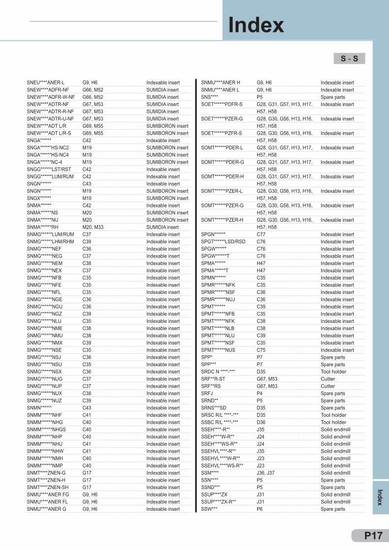
SNEU****ANER-L G9, H6SNEW****ADFR-NF G66, M52SNEW****ADFR-W-NF G66, M52SNEW****ADTR-NF G67, M53SNEW****ADTR-R-NF G67, M53SNEW****ADTR-U-NF G67, M53SNEW****ADT L/R G69, M55SNEW****ADT L/R-S G69, M55SNGA****** C42SNGA******HS-NC2 M19SNGA******HS-NC4 M19SNGA******NC-4 M19SNGG******LST/RST C42SNGG******LUM/RUM C42SNGN****** C43SNGN****** M19SNGX****** M19SNMA****** C42SNMA******NS M20SNMA******NU M20SNMA******RH M20, M33SNMG******LUM/RUM C37SNMG******LHM/RHM C39SNMG******NEF C36SNMG******NEG C37SNMG******NEM C38SNMG******NEX C37SNMG******NFB C35SNMG******NFE C35SNMG******NFL C35SNMG******NGE C36SNMG******NGU C36SNMG******NGZ C39SNMG******NLU C35SNMG******NME C38SNMG******NMU C38SNMG******NMX C39SNMG******NSE C35SNMG******NSJ C36SNMG******NSU C35SNMG******NSX C36SNMG******NUG C37SNMG******NUP C37SNMG******NUX C38SNMG******NUZ C39SNMN****** C43SNMM******NHF C41SNMM******NHG C40SNMM******NHGS C40SNMM******NHP C40SNMM******NHU C41SNMM******NHW C41SNMM******NMH C40SNMM******NMP C40SNMT****ZNEN-G G17SNMT****ZNEN-H G17SNMT****ZNEN-SH G17SNMU****ANER FG G9, H6SNMU****ANER FL G9, H6SNMU****ANER G G9, H6
SNMU****ANER H G9, H6SNMU****ANER L G9, H6SNS**** P5SOET******PDFR-S G28, G31, G57, H13, H17,
H57, H58SOET******PZER-G G28, G30, G56, H13, H16,
H57, H58SOET******PZFR-S G28, G30, G56, H13, H16,
H57, H58SOMT******PDER-L G28, G31, G57, H13, H17,
H57, H58SOMT******PDER-G G28, G31, G57, H13, H17,
H57, H58SOMT******PDER-H G28, G31, G57, H13, H17,
H57, H58SOMT******PZER-L G28, G30, G56, H13, H16,
H57, H58SOMT******PZER-G G28, G30, G56, H13, H16,
H57, H58SOMT******PZER-H G28, G30, G56, H13, H16,
H57, H58SPGN****** C77SPGT******LSD/RSD C76SPGW****** C76SPGW******T C76SPMA****** H47SPMA******T H47SPMN****** C35SPMR******NFK C35SPMR******NSF C36SPMR******NUJ C36SPMT****** C39SPMT******NFB C35SPMT******NFK C38SPMT******NLB C38SPMT******NLU C39SPMT******NSF C35SPMT******NUS C75SPP* P7SPP*** P7SRDC N ****-*** D35SRF**R-ST G67, M53SRF**RS G67, M53SRFJ P4SRND** P5SRNS***SD D35SRSC R/L ****-*** D35SSBC R/L ****-*** D36SSEH****-R** J35SSEH****W-R** J24SSEH****WS-R** J24SSEHVL****-R** J35SSEHVL****W-R** J23SSEHVL****WS-R** J23SSM**** J36, J37SSN**** P5SSND*** P5SSUP****ZX J31SSUP****ZX-R** J31SSW*** P6
P17
S - S
Index
Index
Indexable insertSUMIDIA insertSUMIDIA insertSUMIDIA insertSUMIDIA insertSUMIDIA insertSUMIBORON insertSUMIBORON insertIndexable insertSUMIBORON insertSUMIBORON insertSUMIBORON insertIndexable insertIndexable insertIndexable insertSUMIBORON insertSUMIBORON insertIndexable insertSUMIBORON insertSUMIBORON insertSUMIDIA insertIndexable insertIndexable insertIndexable insertIndexable insertIndexable insertIndexable insertIndexable insertIndexable insertIndexable insertIndexable insertIndexable insertIndexable insertIndexable insertIndexable insertIndexable insertIndexable insertIndexable insertIndexable insertIndexable insertIndexable insertIndexable insertIndexable insertIndexable insertIndexable insertIndexable insertIndexable insertIndexable insertIndexable insertIndexable insertIndexable insertIndexable insertIndexable insertIndexable insertIndexable insertIndexable insertIndexable insertIndexable insertIndexable insertIndexable insert
Indexable insertIndexable insertSpare partsIndexable insert
Indexable insert
Indexable insert
Indexable insert
Indexable insert
Indexable insert
Indexable insert
Indexable insert
Indexable insert
Indexable insertIndexable insertIndexable insertIndexable insertIndexable insertIndexable insertIndexable insertIndexable insertIndexable insertIndexable insertIndexable insertIndexable insertIndexable insertIndexable insertIndexable insertIndexable insertIndexable insertSpare partsSpare partsTool holderCutterCutterSpare partsSpare partsSpare partsTool holderTool holderSolid endmillSolid endmillSolid endmillSolid endmillSolid endmillSolid endmillSolid endmillSpare partsSpare partsSolid endmillSolid endmillSpare parts

STAC R/L ****-*** D37STER**** F54STFH**-* F46STFS R/L ****-* F46STGC R/L ****-*** D37STIR*** F55STPD*** P6STW*** P6SUF*S R/L G14SVJB R/L ****-*** D38SVLC R/L ****-*** D39SVP** D38, E21, E22SVPB R/L ****-*** D38SVPC R/L ****-*** D39SVVB N ****-*** D38SVW*** P5SWW P6
TTBGN****** C86TBGN******B M20TBGN******NF M20TBGR******LW C86TBGT******LFW/RFW C78TBGT******LFX/RFX C78TBGT******LFY/RFY C78TBGT******LW/RW C78TBGW****** C78TBGW******NF M20TCGT******LFX/RFX C79TCGT******LFY/RFY C79TCGT******M NSC C79TCGT******M NSI C79TCGT******NAG C79TCGW******NC M21TCGW******NC-3 M21TCGW******NU M21TCMT******NF M21TCMT******NFB C80TCMT******NFP C80TCMT******NLB C80TCMT******NLU C80TCMT******NSK C80TCMT******NSU C80TCMW****** C80TCS**T* P6TEGN****** C87TGA R/L ****BF F41TGA R/L ****(E) F42TGA R/L ****R F43TGA R/L *T** F43TF** M42TH*** P8TME****R F53, F54TME***R F53, F54TMI****R F53, F55TMI***R F53, F55TNGA****** C52
TNGA******HS-NC3 M22TNGA******HS-NC6 M22TNGA******LE-NC3 M22TNGA******LS-NC3 M22TNGA******LT-NC3 M22TNGA******LF-NU3 M23TNGA******NC6 M22TNGA******NU3 M23TNGG******LFT/RFT C51TNGG******LFY/RFY C51TNGG******LFX/RFX C51TNGG******LST/RST C51TNGG******LUM/RUM C52TNGG******N-FV NC6 M22TNGG******N-LV NC6 M22TNGG******NGH C52TNGG******NSU C51TNGG******N-SV NC6 M22TNGM******N-LV NU3 M23TNMA****** C50TNMA****** M24TNMA******NU M24TNMG******LHM/RHM C48TNMG******LUM/RUM C46TNMG******NEF C44TNMG******NEG C46TNMG******NEM C47TNMG******NEX C46TNMG******NFA C44TNMG******NFB C44TNMG******NFE C44TNMG******NFL C44TNMG******NGE C45TNMG******NGU C45TNMG******NGZ C48TNMG******NLU C44TNMG******NME C47TNMG******NMU C47TNMG******NMX C47TNMG******NSE C45TNMG******NSU C44TNMG******NSX C45TNMG******NUG C46TNMG******NUP C46TNMG******NUX C47TNMG******NUZ C48TNMM******NHG C49TNMM******NHP C49TNMM******NMP C49TNMM****** C49TNS**** P6TNS****B P6TPGN****** C86TPGN******NF M24TPGN******NU M24TPGR******LW/RW C86TPGT******LFW/RFW C81TPGT******LFX/RFX C81TPGT******LFY/RFY C82TPGT******LSD/RSD C83
P18
S - T
Inde
x
Index
Tool holderTool holderTool holderTool holderTool holderTool holderSpare partsSpare partsSpare partsTool holderTool holderSpare partsTool holderTool holderTool holderSpare partsSpare parts
Indexable insertSUMIBORON insertSUMIDIA insertIndexable insertIndexable insertIndexable insertIndexable insertIndexable insertIndexable insertSUMIDIA insertIndexable insertIndexable insertIndexable insertIndexable insertIndexable insertSUMIBORON insertSUMIBORON insertSUMIBORON insertSUMIDIA insertIndexable insertIndexable insertIndexable insertIndexable insertIndexable insertIndexable insertIndexable insertSpare partsIndexable insertIndexable insertIndexable insertIndexable insertIndexable insertSpare partsSpare partsIndexable insertIndexable insertIndexable insertIndexable insertIndexable insert
SUMIBORON insertSUMIBORON insertSUMIBORON insertSUMIBORON insertSUMIBORON insertSUMIBORON insertSUMIBORON insertSUMIBORON insertIndexable insertIndexable insertIndexable insertIndexable insertIndexable insertSUMIBORON insertSUMIBORON insertIndexable insertIndexable insertSUMIBORON insertSUMIBORON insertIndexable insertSUMIBORON insertSUMIBORON insertIndexable insertIndexable insertIndexable insertIndexable insertIndexable insertIndexable insertIndexable insertIndexable insertIndexable insertIndexable insertIndexable insertIndexable insertIndexable insertIndexable insertIndexable insertIndexable insertIndexable insertIndexable insertIndexable insertIndexable insertIndexable insertIndexable insertIndexable insertIndexable insertIndexable insertIndexable insertIndexable insertIndexable insertSpare partsSpare partsIndexable insertSUMIDIA insertSUMIBORON insertIndexable insertIndexable insertIndexable insertIndexable insertIndexable insert
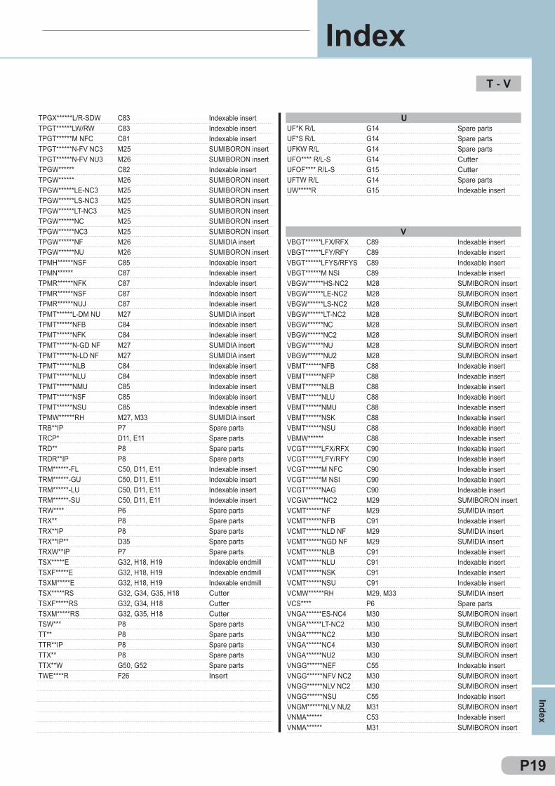
TPGX******L/R-SDW C83TPGT******LW/RW C83TPGT******M NFC C81TPGT******N-FV NC3 M25TPGT******N-FV NU3 M26TPGW****** C82TPGW****** M26TPGW******LE-NC3 M25TPGW******LS-NC3 M25TPGW******LT-NC3 M25TPGW******NC M25TPGW******NC3 M25TPGW******NF M26TPGW******NU M26TPMH******NSF C85TPMN****** C87TPMR******NFK C87TPMR******NSF C87TPMR******NUJ C87TPMT******L-DM NU M27TPMT******NFB C84TPMT******NFK C84TPMT******N-GD NF M27TPMT******N-LD NF M27TPMT******NLB C84TPMT******NLU C84TPMT******NMU C85TPMT******NSF C85TPMT******NSU C85TPMW******RH M27, M33TRB**IP P7TRCP* D11, E11TRD** P8TRDR**IP P8TRM******-FL C50, D11, E11TRM******-GU C50, D11, E11TRM******-LU C50, D11, E11TRM******-SU C50, D11, E11TRW**** P6TRX** P8TRX**IP P8TRX**IP** D35TRXW**IP P7TSX*****E G32, H18, H19TSXF*****E G32, H18, H19TSXM*****E G32, H18, H19TSX*****RS G32, G34, G35, H18TSXF*****RS G32, G34, H18TSXM*****RS G32, G35, H18TSW*** P8TT** P8TTR**IP P8TTX** P8TTX**W G50, G52TWE****R F26
UUF*K R/L G14UF*S R/L G14UFKW R/L G14UFO**** R/L-S G14UFOF**** R/L-S G15UFTW R/L G14UW*****R G15
VVBGT******LFX/RFX C89VBGT******LFY/RFY C89VBGT******LFYS/RFYS C89VBGT******M NSI C89VBGW******HS-NC2 M28VBGW******LE-NC2 M28VBGW******LS-NC2 M28VBGW******LT-NC2 M28VBGW******NC M28VBGW******NC2 M28VBGW******NU M28VBGW******NU2 M28VBMT******NFB C88VBMT******NFP C88VBMT******NLB C88VBMT******NLU C88VBMT******NMU C88VBMT******NSK C88VBMT******NSU C88VBMW****** C88VCGT******LFX/RFX C90VCGT******LFY/RFY C90VCGT******M NFC C90VCGT******M NSI C90VCGT******NAG C90VCGW******NC2 M29VCMT******NF M29VCMT******NFB C91VCMT******NLD NF M29VCMT******NGD NF M29VCMT******NLB C91VCMT******NLU C91VCMT******NSK C91VCMT******NSU C91VCMW******RH M29, M33VCS**** P6VNGA******ES-NC4 M30VNGA******LT-NC2 M30VNGA******NC2 M30VNGA******NC4 M30VNGA******NU2 M30VNGG******NEF C55VNGG******NFV NC2 M30VNGG******NLV NC2 M30VNGG******NSU C55VNGM******NLV NU2 M31VNMA****** C53VNMA****** M31
P19
T - V
Index
Index
Indexable insertIndexable insertIndexable insertSUMIBORON insertSUMIBORON insertIndexable insertSUMIBORON insertSUMIBORON insertSUMIBORON insertSUMIBORON insertSUMIBORON insertSUMIBORON insertSUMIDIA insertSUMIBORON insertIndexable insertIndexable insertIndexable insertIndexable insertIndexable insertSUMIDIA insertIndexable insertIndexable insertSUMIDIA insertSUMIDIA insertIndexable insertIndexable insertIndexable insertIndexable insertIndexable insertSUMIDIA insertSpare partsSpare partsSpare partsSpare partsIndexable insertIndexable insertIndexable insertIndexable insertSpare partsSpare partsSpare partsSpare partsSpare partsIndexable endmillIndexable endmillIndexable endmillCutterCutterCutterSpare partsSpare partsSpare partsSpare partsSpare partsInsert
Spare partsSpare partsSpare partsCutterCutterSpare partsIndexable insert
Indexable insertIndexable insertIndexable insertIndexable insertSUMIBORON insertSUMIBORON insertSUMIBORON insertSUMIBORON insertSUMIBORON insertSUMIBORON insertSUMIBORON insertSUMIBORON insertIndexable insertIndexable insertIndexable insertIndexable insertIndexable insertIndexable insertIndexable insertIndexable insertIndexable insertIndexable insertIndexable insertIndexable insertIndexable insertSUMIBORON insertSUMIDIA insertIndexable insertSUMIDIA insertSUMIDIA insertIndexable insertIndexable insertIndexable insertIndexable insertSUMIDIA insertSpare partsSUMIBORON insertSUMIBORON insertSUMIBORON insertSUMIBORON insertSUMIBORON insertIndexable insertSUMIBORON insertSUMIBORON insertIndexable insertSUMIBORON insertIndexable insertSUMIBORON insert
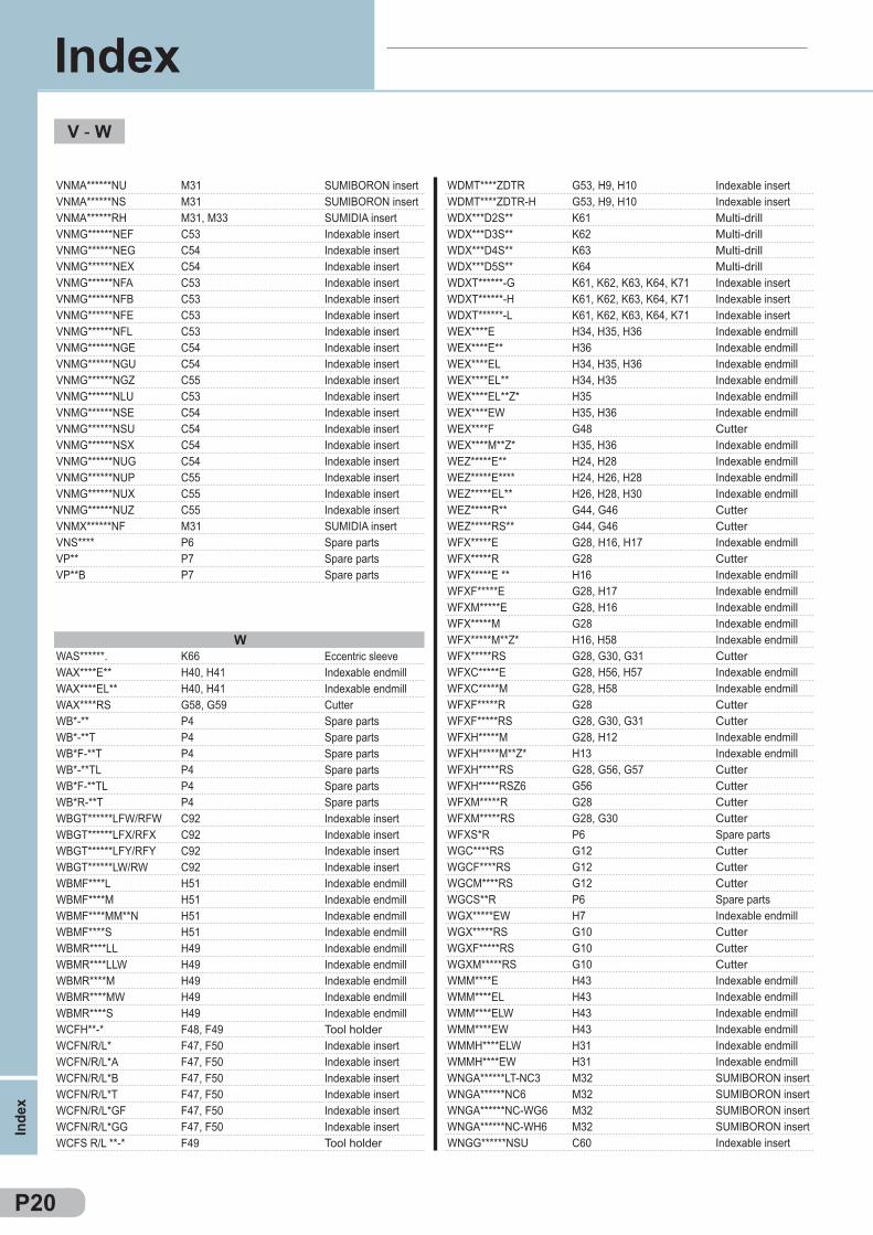
VNMA******NU M31VNMA******NS M31VNMA******RH M31, M33VNMG******NEF C53VNMG******NEG C54VNMG******NEX C54VNMG******NFA C53VNMG******NFB C53VNMG******NFE C53VNMG******NFL C53VNMG******NGE C54VNMG******NGU C54VNMG******NGZ C55VNMG******NLU C53VNMG******NSE C54VNMG******NSU C54VNMG******NSX C54VNMG******NUG C54VNMG******NUP C55VNMG******NUX C55VNMG******NUZ C55VNMX******NF M31VNS**** P6VP** P7VP**B P7
WWAS******. K66WAX****E** H40, H41WAX****EL** H40, H41WAX****RS G58, G59WB*-** P4WB*-**T P4WB*F-**T P4WB*-**TL P4WB*F-**TL P4WB*R-**T P4WBGT******LFW/RFW C92WBGT******LFX/RFX C92WBGT******LFY/RFY C92WBGT******LW/RW C92WBMF****L H51WBMF****M H51WBMF****MM**N H51WBMF****S H51WBMR****LL H49WBMR****LLW H49WBMR****M H49WBMR****MW H49WBMR****S H49WCFH**-* F48, F49WCFN/R/L* F47, F50WCFN/R/L*A F47, F50WCFN/R/L*B F47, F50WCFN/R/L*T F47, F50WCFN/R/L*GF F47, F50WCFN/R/L*GG F47, F50WCFS R/L **-* F49
WDMT****ZDTR G53, H9, H10WDMT****ZDTR-H G53, H9, H10WDX***D2S** K61WDX***D3S** K62WDX***D4S** K63WDX***D5S** K64WDXT******-G K61, K62, K63, K64, K71WDXT******-H K61, K62, K63, K64, K71WDXT******-L K61, K62, K63, K64, K71WEX****E H34, H35, H36WEX****E** H36WEX****EL H34, H35, H36WEX****EL** H34, H35WEX****EL**Z* H35WEX****EW H35, H36WEX****F G48WEX****M**Z* H35, H36WEZ*****E** H24, H28WEZ*****E**** H24, H26, H28WEZ*****EL** H26, H28, H30WEZ*****R** G44, G46WEZ*****RS** G44, G46WFX*****E G28, H16, H17WFX*****R G28WFX*****E ** H16WFXF*****E G28, H17WFXM*****E G28, H16WFX*****M G28WFX*****M**Z* H16, H58WFX*****RS G28, G30, G31WFXC*****E G28, H56, H57WFXC*****M G28, H58WFXF*****R G28WFXF*****RS G28, G30, G31WFXH*****M G28, H12WFXH*****M**Z* H13WFXH*****RS G28, G56, G57WFXH*****RSZ6 G56WFXM*****R G28WFXM*****RS G28, G30WFXS*R P6WGC****RS G12WGCF****RS G12WGCM****RS G12WGCS**R P6WGX*****EW H7WGX*****RS G10WGXF*****RS G10WGXM*****RS G10WMM****E H43WMM****EL H43WMM****ELW H43WMM****EW H43WMMH****ELW H31WMMH****EW H31WNGA******LT-NC3 M32WNGA******NC6 M32WNGA******NC-WG6 M32WNGA******NC-WH6 M32WNGG******NSU C60
P20
V - W
Inde
x
Index
SUMIBORON insertSUMIBORON insertSUMIDIA insertIndexable insertIndexable insertIndexable insertIndexable insertIndexable insertIndexable insertIndexable insertIndexable insertIndexable insertIndexable insertIndexable insertIndexable insertIndexable insertIndexable insertIndexable insertIndexable insertIndexable insertIndexable insertSUMIDIA insertSpare partsSpare partsSpare parts
Eccentric sleeveIndexable endmillIndexable endmillCutterSpare partsSpare partsSpare partsSpare partsSpare partsSpare partsIndexable insertIndexable insertIndexable insertIndexable insertIndexable endmillIndexable endmillIndexable endmillIndexable endmillIndexable endmillIndexable endmillIndexable endmillIndexable endmillIndexable endmillTool holderIndexable insertIndexable insertIndexable insertIndexable insertIndexable insertIndexable insertTool holder
Indexable insertIndexable insertMulti-drillMulti-drillMulti-drillMulti-drillIndexable insertIndexable insertIndexable insertIndexable endmillIndexable endmillIndexable endmillIndexable endmillIndexable endmillIndexable endmillCutterIndexable endmillIndexable endmillIndexable endmillIndexable endmillCutterCutterIndexable endmillCutterIndexable endmillIndexable endmillIndexable endmillIndexable endmillIndexable endmillCutterIndexable endmillIndexable endmillCutterCutterIndexable endmillIndexable endmillCutterCutterCutterCutterSpare partsCutterCutterCutterSpare partsIndexable endmillCutterCutterCutterIndexable endmillIndexable endmillIndexable endmillIndexable endmillIndexable endmillIndexable endmillSUMIBORON insertSUMIBORON insertSUMIBORON insertSUMIBORON insertIndexable insert
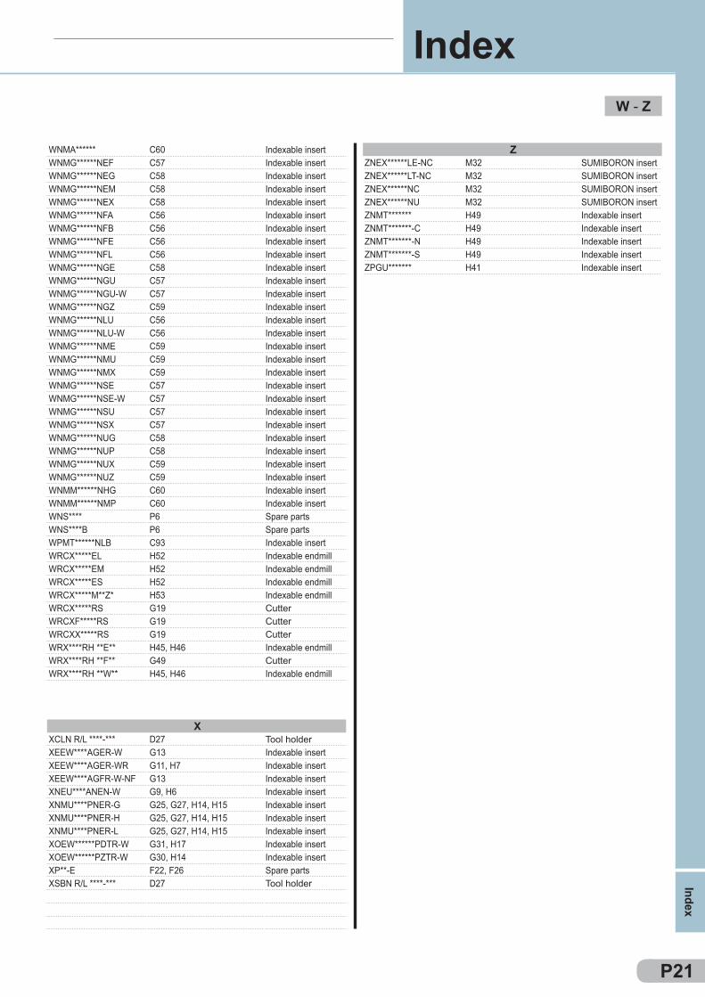
WNMA****** C60WNMG******NEF C57WNMG******NEG C58WNMG******NEM C58WNMG******NEX C58WNMG******NFA C56WNMG******NFB C56WNMG******NFE C56WNMG******NFL C56WNMG******NGE C58WNMG******NGU C57WNMG******NGU-W C57WNMG******NGZ C59WNMG******NLU C56WNMG******NLU-W C56WNMG******NME C59WNMG******NMU C59WNMG******NMX C59WNMG******NSE C57WNMG******NSE-W C57WNMG******NSU C57WNMG******NSX C57WNMG******NUG C58WNMG******NUP C58WNMG******NUX C59WNMG******NUZ C59WNMM******NHG C60WNMM******NMP C60WNS**** P6WNS****B P6WPMT******NLB C93WRCX*****EL H52WRCX*****EM H52WRCX*****ES H52WRCX*****M**Z* H53WRCX*****RS G19WRCXF*****RS G19WRCXX*****RS G19WRX****RH **E** H45, H46WRX****RH **F** G49WRX****RH **W** H45, H46
XXCLN R/L ****-*** D27XEEW****AGER-W G13XEEW****AGER-WR G11, H7XEEW****AGFR-W-NF G13XNEU****ANEN-W G9, H6XNMU****PNER-G G25, G27, H14, H15XNMU****PNER-H G25, G27, H14, H15XNMU****PNER-L G25, G27, H14, H15XOEW******PDTR-W G31, H17XOEW******PZTR-W G30, H14XP**-E F22, F26XSBN R/L ****-*** D27
ZZNEX******LE-NC M32ZNEX******LT-NC M32ZNEX******NC M32ZNEX******NU M32ZNMT******* H49ZNMT*******-C H49ZNMT*******-N H49ZNMT*******-S H49ZPGU******* H41
P21
W - Z
Index
Index
Indexable insertIndexable insertIndexable insertIndexable insertIndexable insertIndexable insertIndexable insertIndexable insertIndexable insertIndexable insertIndexable insertIndexable insertIndexable insertIndexable insertIndexable insertIndexable insertIndexable insertIndexable insertIndexable insertIndexable insertIndexable insertIndexable insertIndexable insertIndexable insertIndexable insertIndexable insertIndexable insertIndexable insertSpare partsSpare partsIndexable insertIndexable endmillIndexable endmillIndexable endmillIndexable endmillCutterCutterCutterIndexable endmillCutterIndexable endmill
Tool holderIndexable insertIndexable insertIndexable insertIndexable insertIndexable insertIndexable insertIndexable insertIndexable insertIndexable insertSpare partsTool holder
SUMIBORON insertSUMIBORON insertSUMIBORON insertSUMIBORON insertIndexable insertIndexable insertIndexable insertIndexable insertIndexable insert

NotesSAFETY INSTRUCTIONS
Target Products Hazards Measures
General precautions for cutting tools
The tools have sharp cutting edges. There is a risk of injury if held directly with bare hands.
Always wear protective equipment, such as protective tools when removing the tool from the case or mounting it onto a machine.
Improper use or incorrect use conditions may cause the tool to breake or scatter, and could cause injury.
Always use protective equipment such as safety covers and protective eyewear.Always use within the scope of the recommended conditions. Refer to the intruction manual, catalogue and other relevant documents.
The tool could break and fly off if the cutting force increases suddenly because of impact loads or excessive wear and could cause injury.
Always use protective equipment such as safety covers and protective eyewear.Replace the tool at an early stage.
Very hot chips could scatter or elongated chips could be dischar-ged, and cause injury or burns.
Always use protective equipment such as safety covers and protective eyewear.When removing the chips, always stop the machine, wear protecti-ve gloves, and use tools such as nippers or clippers.
The tool and work materials will become very hot during turning. There is a risk of burn if these are touched directly with bare hands immediately after machining.
Always wear protective equipment such as protective gloves.
There is a risk of igniting or fires from the sparks generated during turning, or the heat generated from broken pieces and chips.
Do not use in an area where there is a risk of fires or explosions.Always provide fire prevention measures when using water-insolu-ble turning oil solution.
When using at a high rotation speed, if the balance including the machine tool holder is poor, the deflection or vibration could cause tool damage and injury.
Always use protective equipment such as safety covers and protective eyewear.Always carry out trial operation, and confirm that there is no deflec-tion, vibration or abnormal noise.
There is a risk of injury if you touch the burrs formed on the work-piece with bare hands.
Do not touch with bare hands.
General precautions for cutting edge inde-xable tools
If insert or parts are not properly clamped, they could come off or fly off during turning and cause injury.
Clean the mounting surface and fixing parts free of foreign matter, before mounting the insert.When mounting, use the enclosed spanner and confirm that the insert and parts are securely clamped. Never use parts other than the designated inserts or parts.
If the parts are tightened excessively with an auxiliary tool such as a pipe, the insert or part could break and come off or fly off.
Do not use auxiliary tools such as pipes. Use the enclosed span-ner.
Using the tool with high-speed rotation is extremely dangerous as the parts or inserts could fly off with the centrifugal force. Pay special attention to safety when handling.
Always use within the scope of the recommended conditions. Refer to the instruction manual, catalog and other relevant documents.
Various cutters and other tools used with rotation
The cutters have very sharp cutting edges. Touching these with bare hands could result in injury.
Always wear protective equipment such as protective gloves.
Tools could sway or vibrate if the eccentric rotation or balance is poor. There is a risk of injury if they break or fly off.
Keep the rotation speed within the scope of the recommended conditions.Periodically adjust the accuracy and balance of the rotating secti-ons so that eccentric rotation or deflection do not occur because of bearing wear, etc.
Drills
When machining a through hole while rotating the workpiece, a disc-shaped uncut section may fly off at the point of penetration. This disc is sharp and very dangerous.
Always use protective equipment such as safety covers and protective eyewear. Also take measures such as attaching a cover to the chuck section.
The very small drill has a pointed end, and is very sharp. It could stab or break when directly touched with a finger, and be difficult to remove. The end could fly off if it breaks.
Take special care to safety when handling. Always wear protective gloves and protective eyewear, etc.
Brazing tool There is a risk of injury if the insert comes off or breaks, etc. Confirm that the insert is properly brazed before using.Do not use in conditions that could become very hot.
Others
Repeated brazing is dangerous as the insert could break during use.
Do not use an insert that has been repeated brazed as the strength will have dropped.
Using this product for a purpose other than the designated applica-tion can break the machine or tool and is very dangerous.
Observe the designated usage.
Finally,this brochure describes the basic safety information. For further information, refer to the instruction manual, catalog and other relevant documents for each tool, or contact Sumitomo Electric Hardmetal. Sumitomo Electric Hardmetal will not be held liable for any damage and injuries resulting from changes to the specifications, including alterations and modifications, made without consent from Sumitomo Electric Hardmetal.

1 2
3
1 2
3
TOOL ENGINEERING SERVICESTOOL ENGINEERING SERVICES
Tool Engineering ServicesIn order to provide a higher level of support and satisfaction for our customers, Sumitomo Electric Industries has created the Tool Engineering Service system.
We have created several Tool Engineering Centers around the world as bases for this support.The Tool Engineering Centers provide a wide range of support to assist user manufacturing activities,
with services including training (at the Center), test cuts, technical consulting, line diagnostics (at the user’s site) and tooling proposals.
Tool Engineering Center Locations
Overseas
►Itami Tool Engineering Center (I-TEC)►Yokohama Tool Engineering Center (Y-TEC)►Hokkaido Igetalloy Tool Engineering Center (H-TEC)►Tokai Tool Engineering Center (T-TEC)►Kyushu Tool Engineering Center (K-TEC)
►Germany / European Design & Engineering Center (E-DEC)►Thailand / Thailand Tool Engineering Center (Ti-TEC)►Shanghai / Shanghai Tool Engineering Center (S-TEC)►U.S.A. / Americas Tool Engineering Center (A-TEC)►Indonesia / Indonesia Tool Engineering Center (In-TEC)►India Tool Engineering Center
Japan
TrainingPerformance evaluation technology
Test cuts and technical consulting
The Tool Engineering Centers can make test cuts on user workpieces, and work with users to create more detailed technical proposals. The Centers can also provide solutions to various machining problems, general line diagnostics for machining lines, and tooling support for new lines.*Contact your nearest SEI sales office for more information.
To attain improvements in machining on sites, manufacturers must rely on more than just the subjective guidance provided by experience and instinct. Today’s advanced measuring instruments can make machining phenomena observable, and clarify problems.
To make it easy for anyone to take part, the Centers offer training courses designed for a variety of different training objectives and participants.*Contact your nearest SEI sales office for detailed training curricula.
Tool Engineering
Services
Training
Test Cuts
Line diagnostics
Technical consulting
Tooling proposals
Tool Engineering Center
On-site consulation

Hokkaido SumidenPrecision Co., Ltd.
HokkaidoPrecision Tool Co., Ltd.
Tokai SumidenPrecision Tool Co., Ltd.
Kyushu SumidenSeimitsu Ltd.
Asdex Corporation Sumitomo ElectricHartmetallfabrik GmbH
Sumitomo Electric Hartmetallfabrik GmbH, organizačni složka.
Sumitomo Electric HardmetalManufacturing (Changzhou) Co., Ltd
Sumitomo Electric HardmetalManufacturing (Thailand), Ltd
PT. Sumiden HardmetalManufacturing Indonesia
Motherson Techno ToolsLtd.
Sumitomo Electric CarbideManufacturing, Inc. (WI)
Sumitomo Electric CarbideManufacturing, Inc. (OH)
Tool Engineering CenterSumitomo ElectricIndustries Ltd. Hardmetal Div.Sumitomo ElectricHardmetal Corp.
CUTTING TOOLS
WORLDWIDE LOCATIONS
Sales Network
Production Network
Production Network
We are strengthening its global position for high-quality products and services, while contributing technology to market needs around the world.

Itami Tool Engineering Center (I-Tec)Hokkaido Tool Engineering Center (H-Tec)Yokohama Tool Engineering Center (Y-Tec)Tokai Tool Engineering Center (T-Tec)Kyushu Tool Engineering Center (K-Tec)
European Design & Engineering Center (E-DEC)Shanghai Tool Engineering Center (S-Tec)Thai Tool Engineering Center (Ti-Tec)Indonesia Tool Engineering Center (In-Tec)Americas Tool Engineering Center (A-Tec)India Tool Engineering Center
Sumitomo ElectricHartmetall GmbH
Sumitomo Electric ToolNet, Inc.
Sumitomo ElectricHardmetal Ltd.
SumiSermetal Ticaret veSanayi Limited Şirketi
Sumitomo Electric Hardmetal Trading (Shanghai) Co., Ltd.
Superior Engineering Tool Trading (Shanghai) Co., Ltd.
Sumitomo Electric Hardmetal Asia Pacific Pte Ltd.
Sumitomo Electric Hardmetal (Thailand) Ltd.
PT. Sumitomo Electric Hardmetal Indonesia
SEI Carbide AustraliaPty Ltd.
Motherson Techno Tools Ltd.
Sumitomo Electric Carbide, Inc.
Sumicarbide Canada Inc. Sumitomo Electric Hardmetal de Mexico, S.A. de C.V.
Sumitomo Electric Hardmetal do Brasil Ltda.
Taiwan Hong-Yu Precision Tool Co., Ltd.
Tool Engineering Center
CUTTING TOOLS
EUROPEAN LOCATIONS
Sales Network
Production Network
Sales Network