Section 8 Topics - Diagramas dediagramas.diagramasde.com/otros/Inmv Toyota.pdf · 673 Electronic &...
32
Technician Handbook 673 Electronic & Computer Controlled Systems • Engine Immobilizer • WORKSHEET: Immobilizer System • Power Distributor • Smart Junction Box (MICON) • HID Headlights • Dynamic Laser Cruise Control Section 8 Topics Electronic Systems Technical Training 135
Transcript of Section 8 Topics - Diagramas dediagramas.diagramasde.com/otros/Inmv Toyota.pdf · 673 Electronic &...
Technician Handbook673 Electronic & Computer Controlled Systems
• Engine Immobilizer• WORKSHEET: Immobilizer System• Power Distributor• Smart Junction Box (MICON)• HID Headlights• Dynamic Laser Cruise Control
Section 8 Topics
Electronic Systems
Technical Training 135
Technician Handbook673 Electronic & Computer Controlled Systems
Key Cylinder
Transponder Key Coil Transponder Key
Amplifier
SecurityIndicator
Light
DLC3
TransponderKey ECU
ECM
Communication
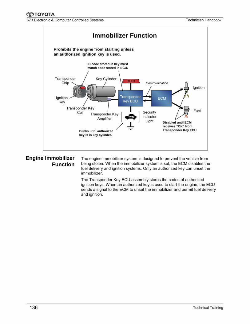
Immobilizer Function
Prohibits the engine from starting unless an authorized ignition key is used.
ID code stored in key must match code stored in ECU.
Disabled until ECM receives “OK” from Transponder Key ECUBlinks until authorized
key is in key cylinder.
Transponder Chip
Ignition Key
Ignition
Fuel
The engine immobilizer system is designed to prevent the vehicle from being stolen. When the immobilizer system is set, the ECM disables the fuel delivery and ignition systems. Only an authorized key can unset the immobilizer.The Transponder Key ECU assembly stores the codes of authorized ignition keys. When an authorized key is used to start the engine, the ECU sends a signal to the ECM to unset the immobilizer and permit fuel delivery and ignition.
Engine Immobilizer Function
Technical Training136
Technician Handbook673 Electronic & Computer Controlled Systems
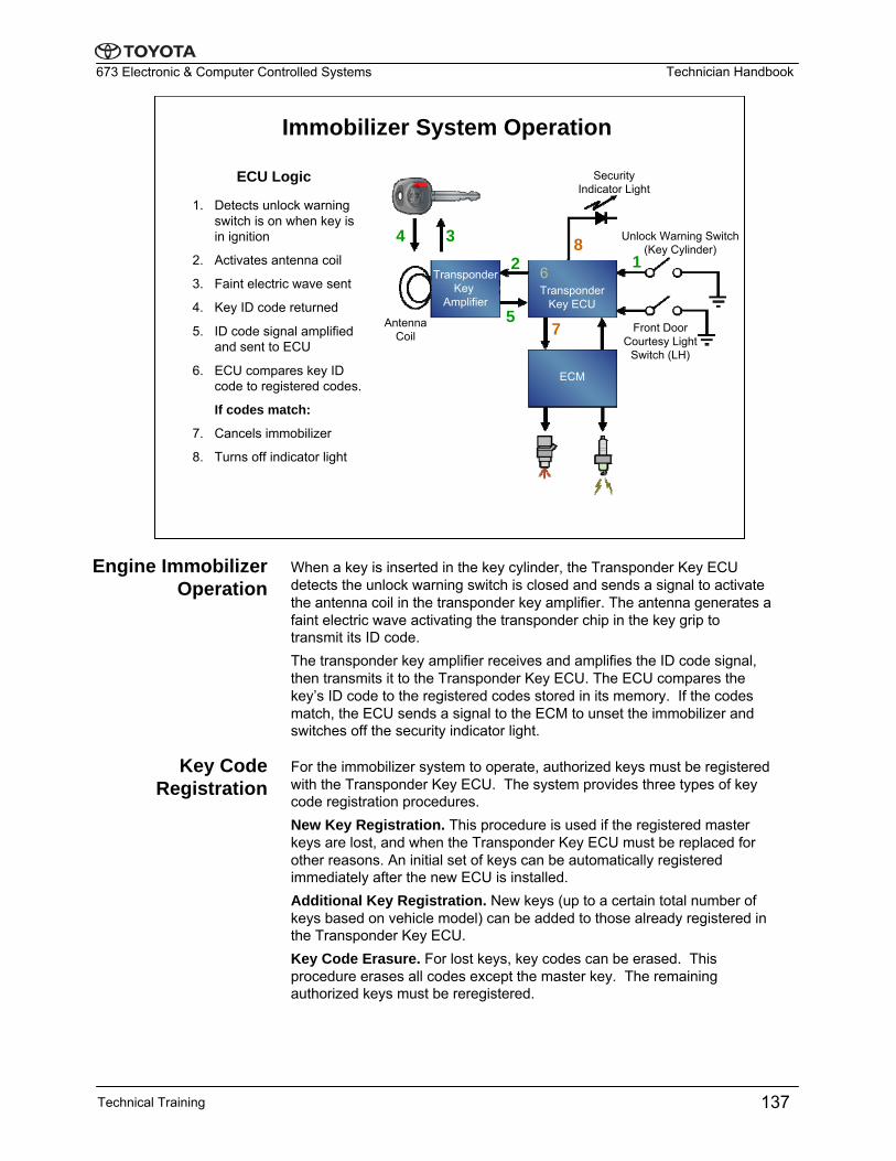
Immobilizer System Operation
1. Detects unlock warning switch is on when key is in ignition
2. Activates antenna coil
3. Faint electric wave sent
4. Key ID code returned
5. ID code signal amplified and sent to ECU
6. ECU compares key ID code to registered codes.
If codes match:
7. Cancels immobilizer
8. Turns off indicator light
1234
5
6
7
8
ECU Logic
ECM
TransponderKey ECU
TransponderKey
Amplifier
Unlock Warning Switch (Key Cylinder)
Front Door Courtesy Light
Switch (LH)
Security Indicator Light
Antenna Coil
When a key is inserted in the key cylinder, the Transponder Key ECU detects the unlock warning switch is closed and sends a signal to activate the antenna coil in the transponder key amplifier. The antenna generates a faint electric wave activating the transponder chip in the key grip to transmit its ID code. The transponder key amplifier receives and amplifies the ID code signal, then transmits it to the Transponder Key ECU. The ECU compares the key’s ID code to the registered codes stored in its memory. If the codes match, the ECU sends a signal to the ECM to unset the immobilizer and switches off the security indicator light.
For the immobilizer system to operate, authorized keys must be registered with the Transponder Key ECU. The system provides three types of key code registration procedures.New Key Registration. This procedure is used if the registered master keys are lost, and when the Transponder Key ECU must be replaced for other reasons. An initial set of keys can be automatically registered immediately after the new ECU is installed. Additional Key Registration. New keys (up to a certain total number of keys based on vehicle model) can be added to those already registered in the Transponder Key ECU.Key Code Erasure. For lost keys, key codes can be erased. This procedure erases all codes except the master key. The remainingauthorized keys must be reregistered.
Engine Immobilizer Operation
Key Code Registration
Technical Training 137
Technician Handbook673 Electronic & Computer Controlled Systems
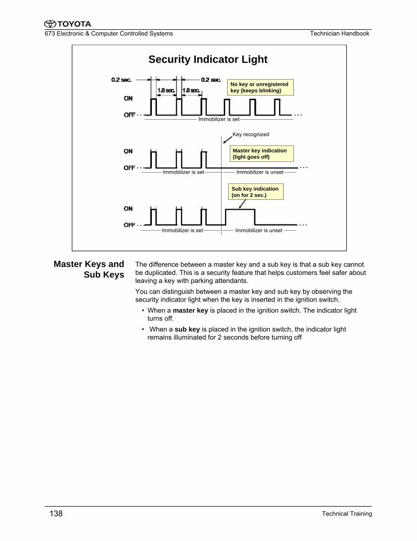
Sub key indication (on for 2 sec.)
Immobilizer is set Immobilizer is unset
Key recognized
Immobilizer is set Immobilizer is unset
Security Indicator Light
Master key indication (light goes off)
…
…
…
…
…
…
No key or unregistered key (keeps blinking)
Immobilizer is set
The difference between a master key and a sub key is that a sub key cannot be duplicated. This is a security feature that helps customers feel safer about leaving a key with parking attendants.You can distinguish between a master key and sub key by observing the security indicator light when the key is inserted in the ignition switch.
• When a master key is placed in the ignition switch. The indicator light turns off.
• When a sub key is placed in the ignition switch, the indicator light remains illuminated for 2 seconds before turning off
Master Keys and Sub Keys
Technical Training138
Technician Handbook673 Electronic & Computer Controlled Systems
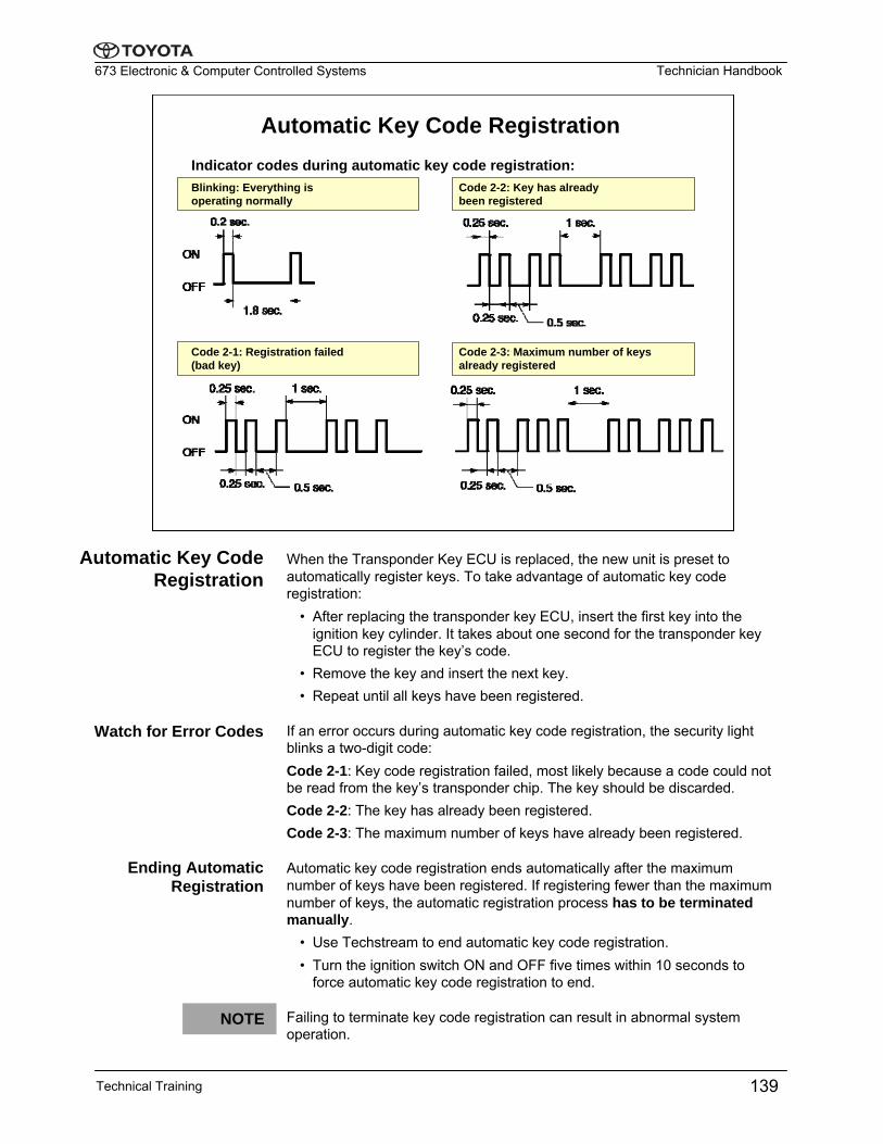
Automatic Key Code RegistrationIndicator codes during automatic key code registration:
Code 2-1: Registration failed (bad key)
Code 2-3: Maximum number of keys already registered
Code 2-2: Key has already been registered
Blinking: Everything is operating normally
When the Transponder Key ECU is replaced, the new unit is preset to automatically register keys. To take advantage of automatic key code registration:
• After replacing the transponder key ECU, insert the first key into the ignition key cylinder. It takes about one second for the transponder key ECU to register the key’s code.
• Remove the key and insert the next key.• Repeat until all keys have been registered.
If an error occurs during automatic key code registration, the security light blinks a two-digit code:Code 2-1: Key code registration failed, most likely because a code could not be read from the key’s transponder chip. The key should be discarded. Code 2-2: The key has already been registered.Code 2-3: The maximum number of keys have already been registered.
Automatic key code registration ends automatically after the maximum number of keys have been registered. If registering fewer than the maximum number of keys, the automatic registration process has to be terminated manually.
• Use Techstream to end automatic key code registration.• Turn the ignition switch ON and OFF five times within 10 seconds to
force automatic key code registration to end.
Failing to terminate key code registration can result in abnormal system operation.
Automatic Key Code Registration
Watch for Error Codes
Ending Automatic Registration
NOTE
Technical Training 139
Technician Handbook673 Electronic & Computer Controlled Systems
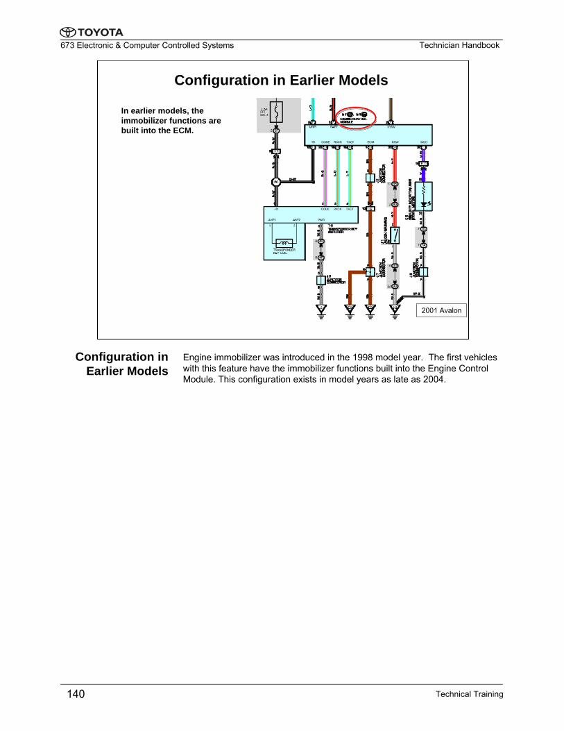
Configuration in Earlier Models
In earlier models, the immobilizer functions are built into the ECM.
2001 Avalon
Engine immobilizer was introduced in the 1998 model year. The first vehicles with this feature have the immobilizer functions built into the Engine Control Module. This configuration exists in model years as late as 2004.
Configuration in Earlier Models
Technical Training140
Technician Handbook673 Electronic & Computer Controlled Systems
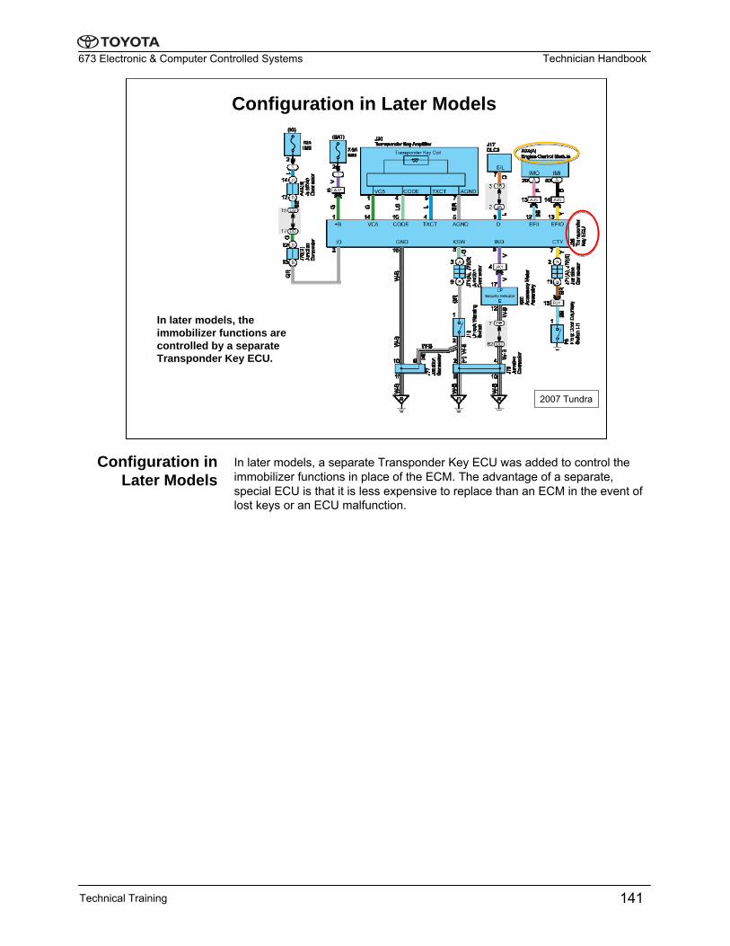
Configuration in Later Models
2007 Tundra
In later models, the immobilizer functions are controlled by a separate Transponder Key ECU.
In later models, a separate Transponder Key ECU was added to control the immobilizer functions in place of the ECM. The advantage of a separate, special ECU is that it is less expensive to replace than an ECM in the event of lost keys or an ECU malfunction.
Configuration in Later Models
Technical Training 141
Technician Handbook673 Electronic & Computer Controlled Systems
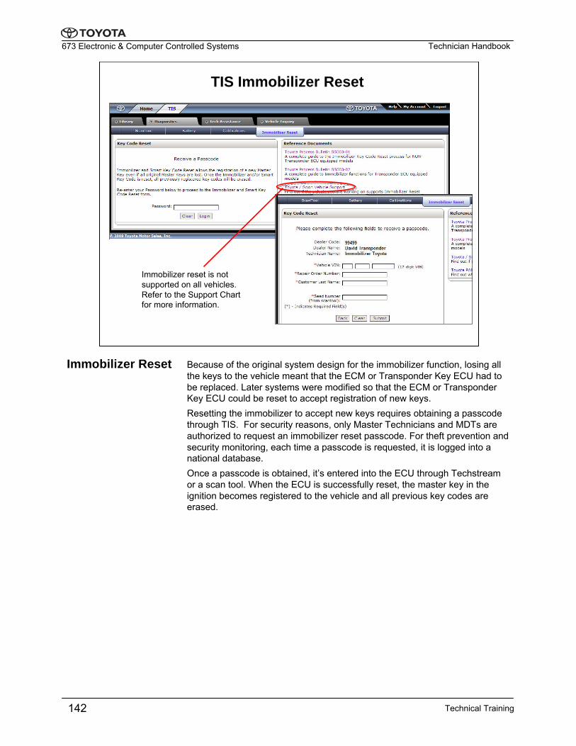
TIS Immobilizer Reset
Immobilizer reset is not supported on all vehicles. Refer to the Support Chart for more information.
Because of the original system design for the immobilizer function, losing all the keys to the vehicle meant that the ECM or Transponder Key ECU had to be replaced. Later systems were modified so that the ECM or Transponder Key ECU could be reset to accept registration of new keys.Resetting the immobilizer to accept new keys requires obtaining a passcodethrough TIS. For security reasons, only Master Technicians and MDTs are authorized to request an immobilizer reset passcode. For theft prevention and security monitoring, each time a passcode is requested, it is logged into a national database.Once a passcode is obtained, it’s entered into the ECU through Techstream or a scan tool. When the ECU is successfully reset, the master key in the ignition becomes registered to the vehicle and all previous key codes are erased.
Immobilizer Reset
Technical Training142
Technician Handbook673 Electronic & Computer Controlled Systems
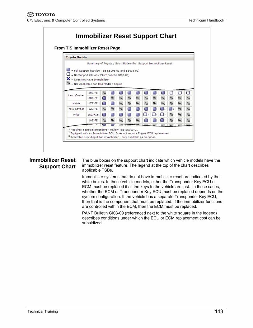
Immobilizer Reset Support Chart
From TIS Immobilizer Reset Page
The blue boxes on the support chart indicate which vehicle models have the immobilizer reset feature. The legend at the top of the chart describes applicable TSBs.Immobilizer systems that do not have immobilizer reset are indicated by the white boxes. In these vehicle models, either the Transponder Key ECU or ECM must be replaced if all the keys to the vehicle are lost. In these cases, whether the ECM or Transponder Key ECU must be replaced depends on the system configuration. If the vehicle has a separate Transponder Key ECU, then that is the component that must be replaced. If the immobilizer functions are controlled within the ECM, then the ECM must be replaced.PANT Bulletin GI03-09 (referenced next to the white square in the legend) describes conditions under which the ECU or ECM replacement cost can be subsidized.
Immobilizer Reset Support Chart
Technical Training 143
Technician Handbook673 Electronic & Computer Controlled Systems
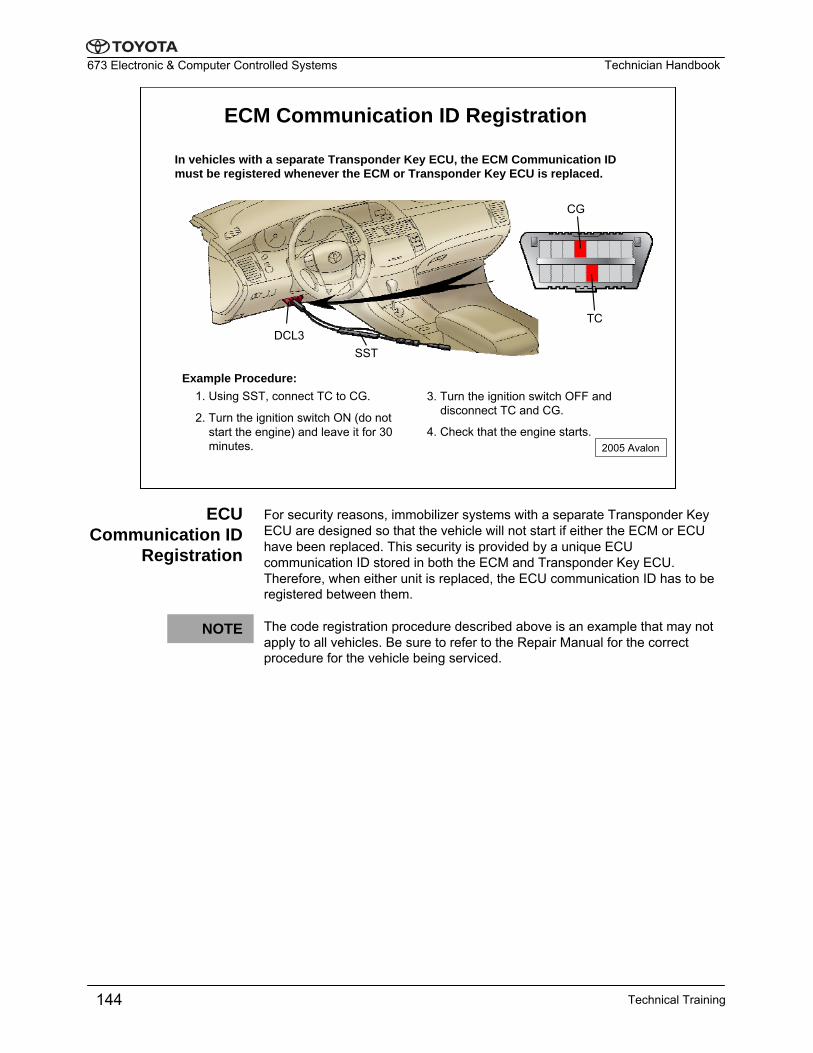
ECM Communication ID Registration
In vehicles with a separate Transponder Key ECU, the ECM Communication ID must be registered whenever the ECM or Transponder Key ECU is replaced.
1. Using SST, connect TC to CG.
2. Turn the ignition switch ON (do not start the engine) and leave it for 30 minutes.
3. Turn the ignition switch OFF and disconnect TC and CG.
4. Check that the engine starts.2005 Avalon
Example Procedure:
CG
TCDCL3
SST
For security reasons, immobilizer systems with a separate Transponder Key ECU are designed so that the vehicle will not start if either the ECM or ECU have been replaced. This security is provided by a unique ECU communication ID stored in both the ECM and Transponder Key ECU.Therefore, when either unit is replaced, the ECU communication ID has to be registered between them.
The code registration procedure described above is an example that may not apply to all vehicles. Be sure to refer to the Repair Manual for the correct procedure for the vehicle being serviced.
ECU Communication ID
Registration
NOTE
Technical Training144
Technician Handbook673 Electronic & Computer Controlled Systems
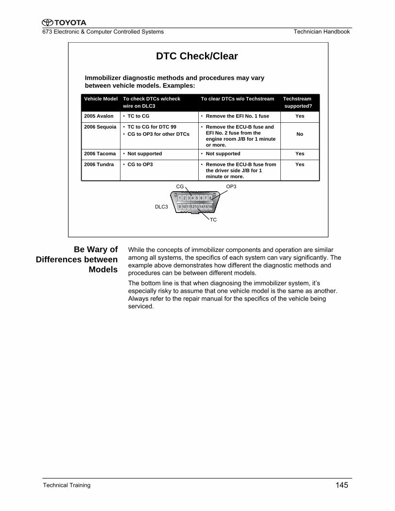
DTC Check/Clear
Immobilizer diagnostic methods and procedures may vary between vehicle models. Examples:
Vehicle Model To check DTCs w/check wire on DLC3
To clear DTCs w/o Techstream Techstreamsupported?
2005 Avalon • TC to CG • Remove the EFI No. 1 fuse Yes
2006 Sequoia • TC to CG for DTC 99• CG to OP3 for other DTCs
• Remove the ECU-B fuse and EFI No. 2 fuse from the engine room J/B for 1 minute or more.
No
2006 Tacoma • Not supported • Not supported Yes
2006 Tundra • CG to OP3 • Remove the ECU-B fuse from the driver side J/B for 1 minute or more.
Yes
CG
TC
OP3
DLC3
1
9 10 111213 1415 16
2 3 4 5 6 7 8
While the concepts of immobilizer components and operation are similar among all systems, the specifics of each system can vary significantly. The example above demonstrates how different the diagnostic methods and procedures can be between different models. The bottom line is that when diagnosing the immobilizer system, it’s especially risky to assume that one vehicle model is the same as another. Always refer to the repair manual for the specifics of the vehicle being serviced.
Be Wary of Differences between
Models
Technical Training 145
Technician Handbook673 Electronic & Computer Controlled Systems
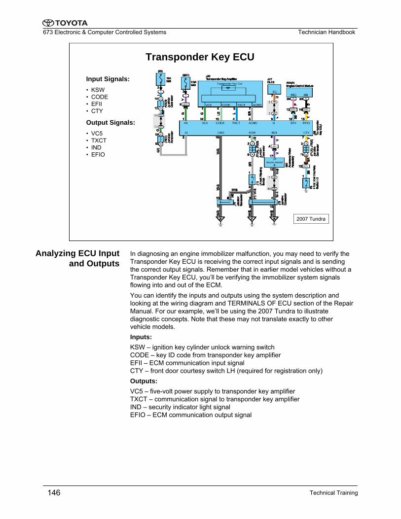
Transponder Key ECU
Input Signals:• KSW• CODE• EFII• CTY
Output Signals:• VC5• TXCT• IND• EFIO
2007 Tundra
In diagnosing an engine immobilizer malfunction, you may need to verify the Transponder Key ECU is receiving the correct input signals and is sending the correct output signals. Remember that in earlier model vehicles without a Transponder Key ECU, you’ll be verifying the immobilizer system signals flowing into and out of the ECM.You can identify the inputs and outputs using the system description and looking at the wiring diagram and TERMINALS OF ECU section of the Repair Manual. For our example, we’ll be using the 2007 Tundra to illustrate diagnostic concepts. Note that these may not translate exactly to other vehicle models.Inputs:KSW – ignition key cylinder unlock warning switchCODE – key ID code from transponder key amplifierEFII – ECM communication input signalCTY – front door courtesy switch LH (required for registration only)Outputs:VC5 – five-volt power supply to transponder key amplifierTXCT – communication signal to transponder key amplifierIND – security indicator light signalEFIO – ECM communication output signal
Analyzing ECU Input and Outputs
Technical Training146
Technician Handbook673 Electronic & Computer Controlled Systems
Transponder Signals
KSW
VC5
TXCT
CODE
2007 Tundra
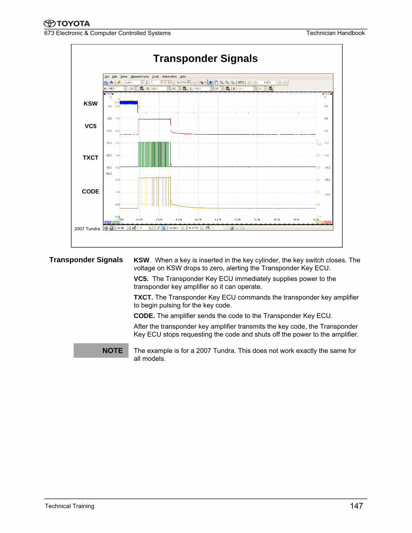
KSW. When a key is inserted in the key cylinder, the key switch closes. The voltage on KSW drops to zero, alerting the Transponder Key ECU.VC5. The Transponder Key ECU immediately supplies power to the transponder key amplifier so it can operate. TXCT. The Transponder Key ECU commands the transponder key amplifier to begin pulsing for the key code. CODE. The amplifier sends the code to the Transponder Key ECU.After the transponder key amplifier transmits the key code, the Transponder Key ECU stops requesting the code and shuts off the power to the amplifier.
The example is for a 2007 Tundra. This does not work exactly the same for all models.
Transponder Signals
Technical Training 147
NOTE
Technician Handbook673 Electronic & Computer Controlled Systems
Transponder Key ECU – Power & Ground
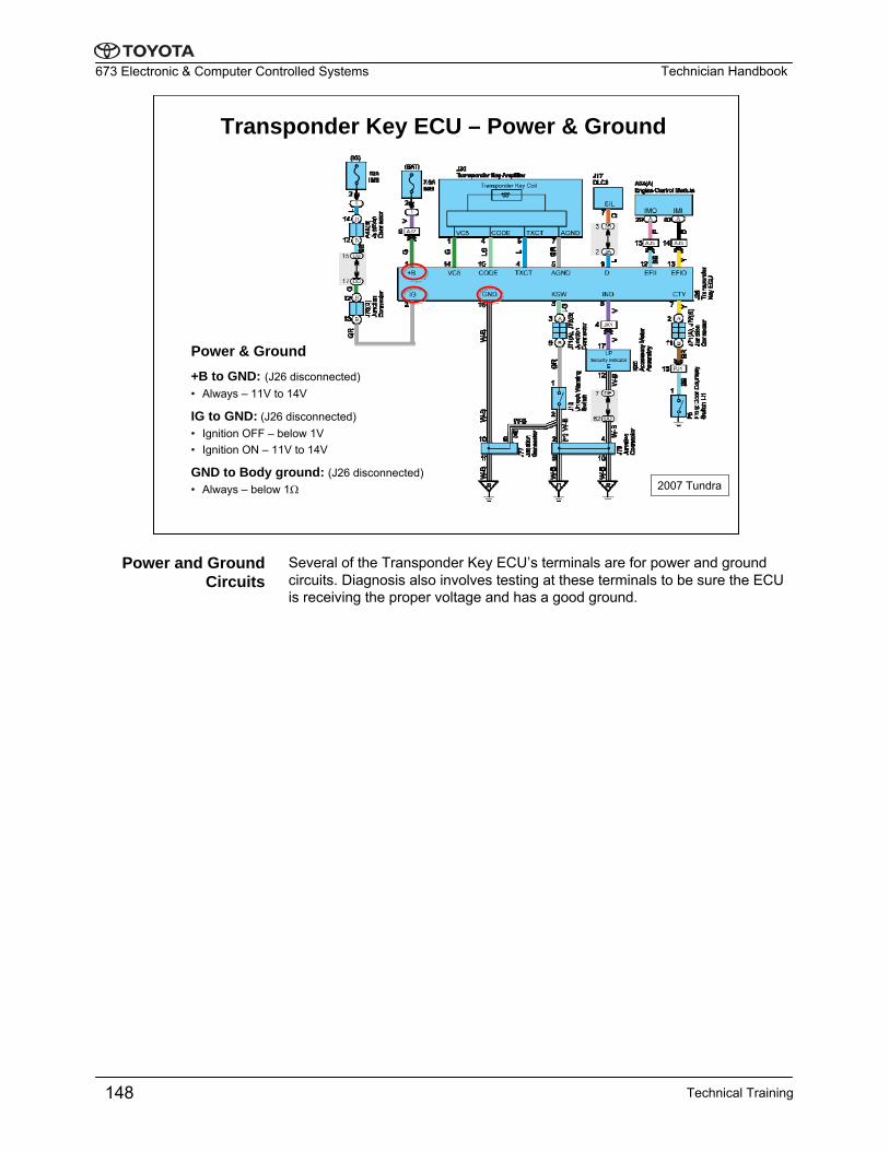
+B to GND: (J26 disconnected)• Always – 11V to 14V
IG to GND: (J26 disconnected)• Ignition OFF – below 1V• Ignition ON – 11V to 14V
GND to Body ground: (J26 disconnected)• Always – below 1Ω
Power & Ground
2007 Tundra
Several of the Transponder Key ECU’s terminals are for power and ground circuits. Diagnosis also involves testing at these terminals to be sure the ECU is receiving the proper voltage and has a good ground.
Power and Ground Circuits
Technical Training148
Technician Handbook673 Electronic & Computer Controlled Systems
Input
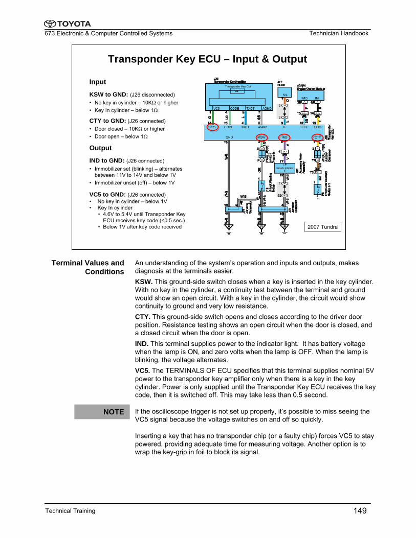
KSW to GND: (J26 disconnected)• No key in cylinder – 10KΩ or higher• Key In cylinder – below 1Ω
CTY to GND: (J26 connected)• Door closed – 10KΩ or higher• Door open – below 1Ω
Output
IND to GND: (J26 connected)• Immobilizer set (blinking) – alternates
between 11V to 14V and below 1V• Immobilizer unset (off) – below 1V
VC5 to GND: (J26 connected)• No key in cylinder – below 1V• Key In cylinder
• 4.6V to 5.4V until Transponder Key ECU receives key code (<0.5 sec.)
• Below 1V after key code received
Transponder Key ECU – Input & Output
2007 Tundra
An understanding of the system’s operation and inputs and outputs, makes diagnosis at the terminals easier.KSW. This ground-side switch closes when a key is inserted in the key cylinder. With no key in the cylinder, a continuity test between the terminal and ground would show an open circuit. With a key in the cylinder, the circuit would show continuity to ground and very low resistance.CTY. This ground-side switch opens and closes according to the driver door position. Resistance testing shows an open circuit when the door is closed, and a closed circuit when the door is open.IND. This terminal supplies power to the indicator light. It has battery voltage when the lamp is ON, and zero volts when the lamp is OFF. When the lamp is blinking, the voltage alternates.VC5. The TERMINALS OF ECU specifies that this terminal supplies nominal 5V power to the transponder key amplifier only when there is a key in the key cylinder. Power is only supplied until the Transponder Key ECU receives the key code, then it is switched off. This may take less than 0.5 second.
If the oscilloscope trigger is not set up properly, it’s possible to miss seeing the VC5 signal because the voltage switches on and off so quickly.
Inserting a key that has no transponder chip (or a faulty chip) forces VC5 to stay powered, providing adequate time for measuring voltage. Another option is to wrap the key-grip in foil to block its signal.
Terminal Values and Conditions
NOTE
Technical Training 149
Technician Handbook673 Electronic & Computer Controlled Systems
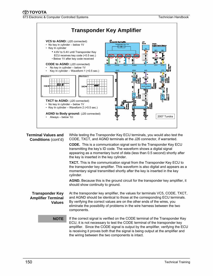
VC5 to AGND: (J20 connected)• No key in cylinder – below 1V• Key In cylinder
• 4.6V to 5.4V until Transponder Key ECU receives key code (<0.5 sec.)
• Below 1V after key code received
CODE to AGND: (J20 connected)• No key in cylinder – below 1V• Key In cylinder – Waveform 1 (<0.5 sec.)
Transponder Key Amplifier
2007 Tundra
TXCT to AGND: (J20 connected)• No key in cylinder – below 1V• Key In cylinder – Waveform 2 (<0.5 sec.)
AGND to Body ground: (J20 connected)• Always – below 1Ω
While testing the Transponder Key ECU terminals, you would also test the CODE, TXCT, and AGND terminals at the J26 connector, if warranted.CODE. This is a communication signal sent to the Transponder Key ECUtransmitting the key’s ID code. The waveform shows a digital signal appearing as a momentary burst of data (less than 0.5 second) shortly after the key is inserted in the key cylinder.TXCT. This is the communication signal from the Transponder Key ECU to the transponder key amplifier. This waveform is also digital and appears as a momentary signal transmitted shortly after the key is inserted in the key cylinder.AGND. Because this is the ground circuit for the transponder key amplifier, it should show continuity to ground.
At the transponder key amplifier, the values for terminals VC5, CODE, TXCT, and AGND should be identical to those at the corresponding ECU terminals. By verifying the correct values are on the other ends of the wires, you eliminate the possibility of problems in the wire harness between the two components.
If the correct signal is verified on the CODE terminal of the Transponder Key ECU, it is not necessary to test the CODE terminal of the transponder key amplifier. Since the CODE signal is output by the amplifier, verifying the ECU is receiving it proves both that the signal is being output at the amplifier and the wiring between the two components is intact.
Transponder Key Amplifier Terminal
Values
NOTE
Terminal Values and Conditions (cont’d)
Technical Training150
Technician Handbook673 Electronic & Computer Controlled Systems
Engine Control Module
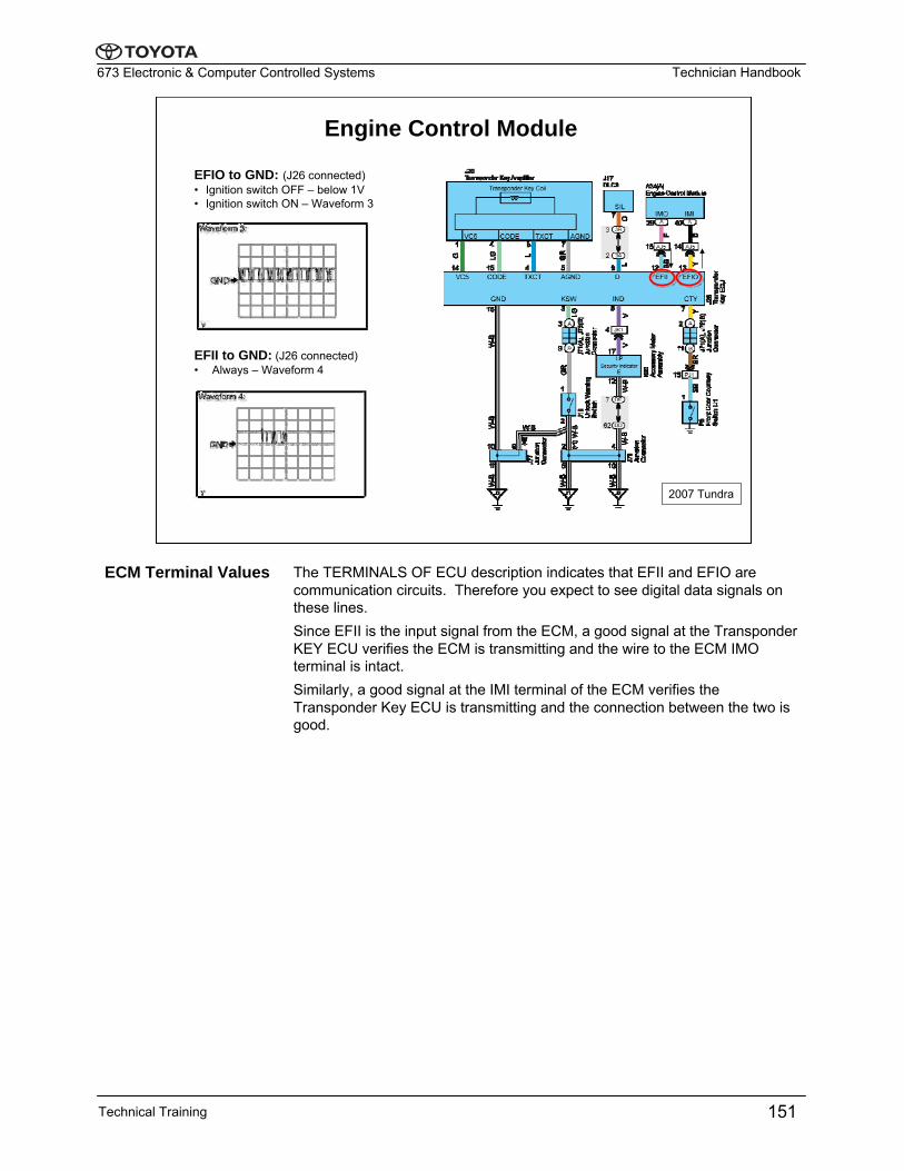
EFIO to GND: (J26 connected)• Ignition switch OFF – below 1V• Ignition switch ON – Waveform 3
2007 Tundra
EFII to GND: (J26 connected)• Always – Waveform 4
The TERMINALS OF ECU description indicates that EFII and EFIO are communication circuits. Therefore you expect to see digital data signals on these lines.Since EFII is the input signal from the ECM, a good signal at the Transponder KEY ECU verifies the ECM is transmitting and the wire to the ECM IMO terminal is intact.Similarly, a good signal at the IMI terminal of the ECM verifies the Transponder Key ECU is transmitting and the connection between the two is good.
ECM Terminal Values
Technical Training 151
Technician Handbook673 Electronic & Computer Controlled Systems
Worksheet
Shop Worksheet:In this worksheet you will:• Use Techstream DATA LIST to make determinations related to the ID Code of the transponder chip embedded in the ignition key• Use a PicoScope to observe Immobilizer System waveforms under varying conditions and compare them to those in the Repair Manual.
Immobilizer
Use this space to write down any questions you may have for your instructor.
NOTES:
Technical Training152
Technician Handbook673 Electronic & Computer Controlled Systems
Power Distributor
Contact Relays• RDI Fan No.1 Relay• RDI Fan No.2 Relay• IGCT Relay • C/OPN Relay• A/F Relay
2006 Highlander HV
Power Distributor
Contact Relays Fuses
Semiconductor Relays
Front
Semiconductor Relays• Back-up Light Relay• Horn Relay• AC Water Pump Relay• Battery Fan Relay
• Head Light Relay LH• Head Light Relay LH• DRL No.2 Relay• DRL No.4 Relay• Rear Defogger Relay
Mode Monitor Terminal
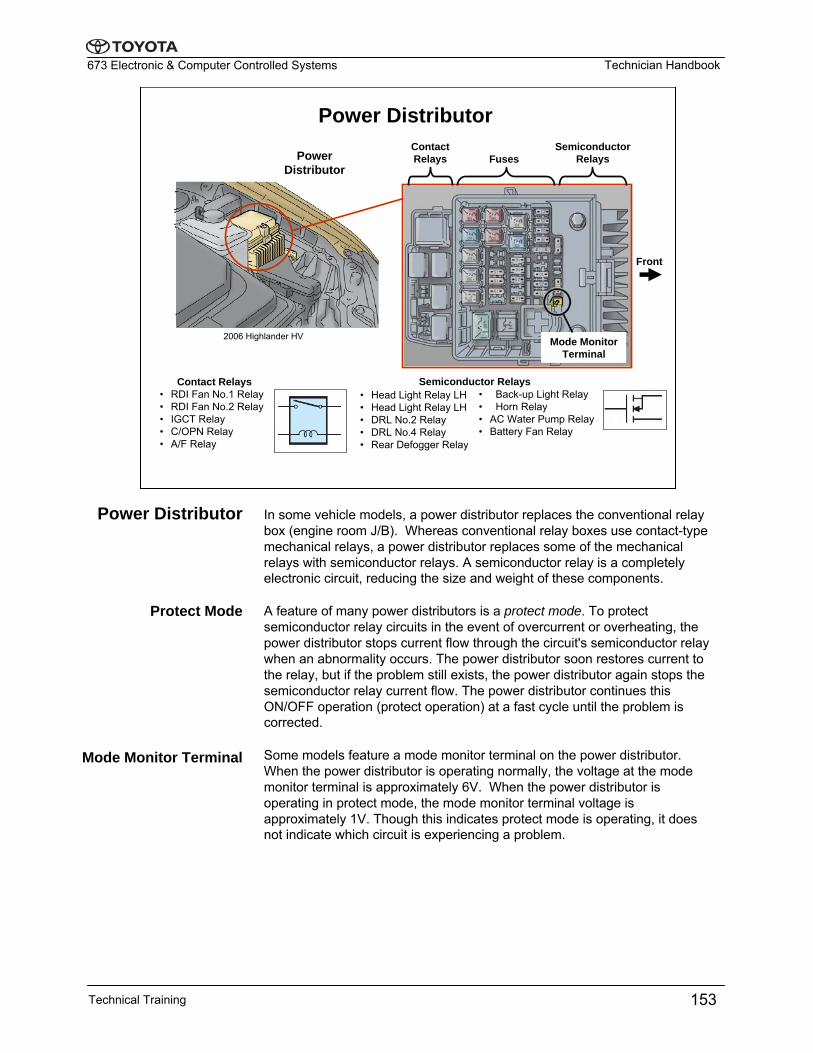
In some vehicle models, a power distributor replaces the conventional relay box (engine room J/B). Whereas conventional relay boxes use contact-type mechanical relays, a power distributor replaces some of the mechanical relays with semiconductor relays. A semiconductor relay is a completely electronic circuit, reducing the size and weight of these components.
A feature of many power distributors is a protect mode. To protect semiconductor relay circuits in the event of overcurrent or overheating, the power distributor stops current flow through the circuit's semiconductor relay when an abnormality occurs. The power distributor soon restores current to the relay, but if the problem still exists, the power distributor again stops the semiconductor relay current flow. The power distributor continues this ON/OFF operation (protect operation) at a fast cycle until the problem is corrected.
Some models feature a mode monitor terminal on the power distributor. When the power distributor is operating normally, the voltage at the mode monitor terminal is approximately 6V. When the power distributor is operating in protect mode, the mode monitor terminal voltage is approximately 1V. Though this indicates protect mode is operating, it does not indicate which circuit is experiencing a problem.
Power Distributor
Protect Mode
Mode Monitor Terminal
Technical Training 153
Technician Handbook673 Electronic & Computer Controlled Systems
Smart Junction Box (MICON)
MICON is short for “Microcomputer Controlled.”
MICON
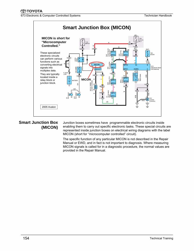
These specialized electronic circuits can perform various functions such as converting electrical signals into multiplex data.They are typically located inside a relay block or junction block.
2005 Avalon
Junction boxes sometimes have programmable electronic circuits inside enabling them to carry out specific electronic tasks. These special circuits are represented inside junction boxes on electrical wiring diagrams with the label MICON (short for “microcomputer controlled” circuit).The specific function of any particular MICON is not described in the Repair Manual or EWD, and in fact is not important to diagnosis. Where measuring MICON signals is called for in a diagnostic procedure, the normal values are provided in the Repair Manual.
Smart Junction Box (MICON)
Technical Training154
Technician Handbook673 Electronic & Computer Controlled Systems
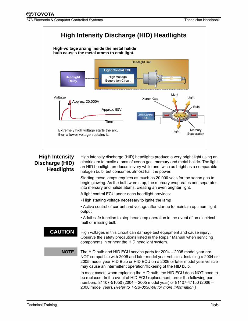
High Intensity Discharge (HID) Headlights
High-voltage arcing inside the metal halide bulb causes the metal atoms to emit light.
Headlight Unit
Time
Voltage Approx. 20,000V
Approx. 85VLight Control
ECU
Xenon GasLight
Light
Light
Bulb
Mercury Evaporation
Extremely high voltage starts the arc, then a lower voltage sustains it.
Light Control ECU
Headlight Relay
High Voltage Generation Circuit
High intensity discharge (HID) headlights produce a very bright light using an electric arc to excite atoms of xenon gas, mercury and metal halide. The light an HID headlight produces is very white and twice as bright as a comparable halogen bulb, but consumes almost half the power.Starting these lamps requires as much as 20,000 volts for the xenon gas to begin glowing. As the bulb warms up, the mercury evaporates and separates into mercury and halide atoms, creating an even brighter light. A light control ECU under each headlight provides:• High starting voltage necessary to ignite the lamp• Active control of current and voltage after startup to maintain optimum light output • A fail-safe function to stop headlamp operation in the event of an electrical fault or missing bulb.
High voltages in this circuit can damage test equipment and cause injury. Observe the safety precautions listed in the Repair Manual when servicing components in or near the HID headlight system.
The HID bulb and HID ECU service parts for 2004 – 2005 model year are NOT compatible with 2006 and later model year vehicles. Installing a 2004 or 2005 model year HID Bulb or HID ECU on a 2006 or later model year vehicle may cause an intermittent operation/flickering of the HID bulb.In most cases, when replacing the HID bulb, the HID ECU does NOT need to be replaced. In the event of HID ECU replacement, order the following part numbers: 81107-51050 (2004 – 2005 model year) or 81107-47150 (2006 –2008 model year). (Refer to T-SB-0030-08 for more information.)
High Intensity Discharge (HID)
Headlights
CAUTION
Technical Training 155
NOTE
Technician Handbook673 Electronic & Computer Controlled Systems
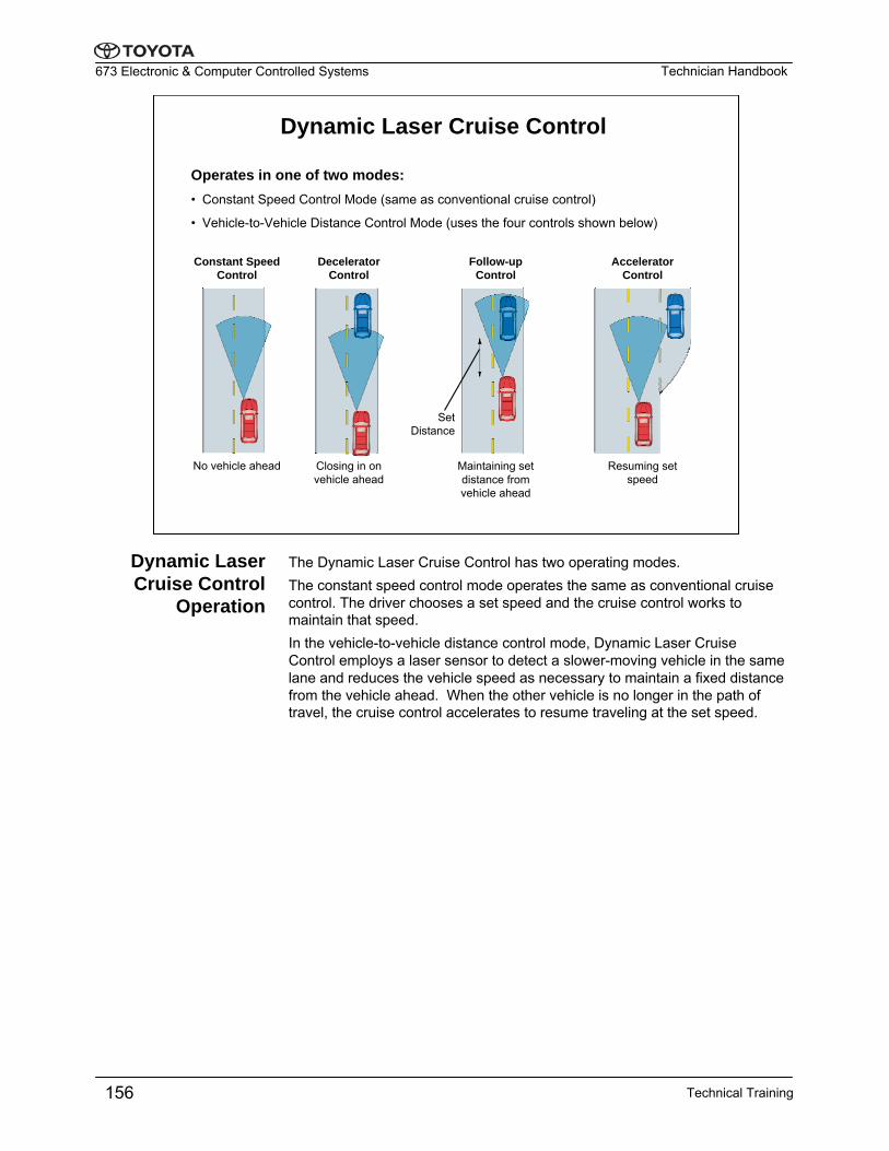
Dynamic Laser Cruise Control
Operates in one of two modes:• Constant Speed Control Mode (same as conventional cruise control)
• Vehicle-to-Vehicle Distance Control Mode (uses the four controls shown below)
Constant Speed Control
No vehicle ahead
Decelerator Control
Accelerator Control
Follow-up Control
Closing in on vehicle ahead
Maintaining set distance from vehicle ahead
Resuming set speed
Set Distance
The Dynamic Laser Cruise Control has two operating modes.The constant speed control mode operates the same as conventional cruise control. The driver chooses a set speed and the cruise control works to maintain that speed.In the vehicle-to-vehicle distance control mode, Dynamic Laser Cruise Control employs a laser sensor to detect a slower-moving vehicle in the same lane and reduces the vehicle speed as necessary to maintain a fixed distance from the vehicle ahead. When the other vehicle is no longer in the path of travel, the cruise control accelerates to resume traveling at the set speed.
Dynamic Laser Cruise Control
Operation
Technical Training156
Technician Handbook673 Electronic & Computer Controlled Systems
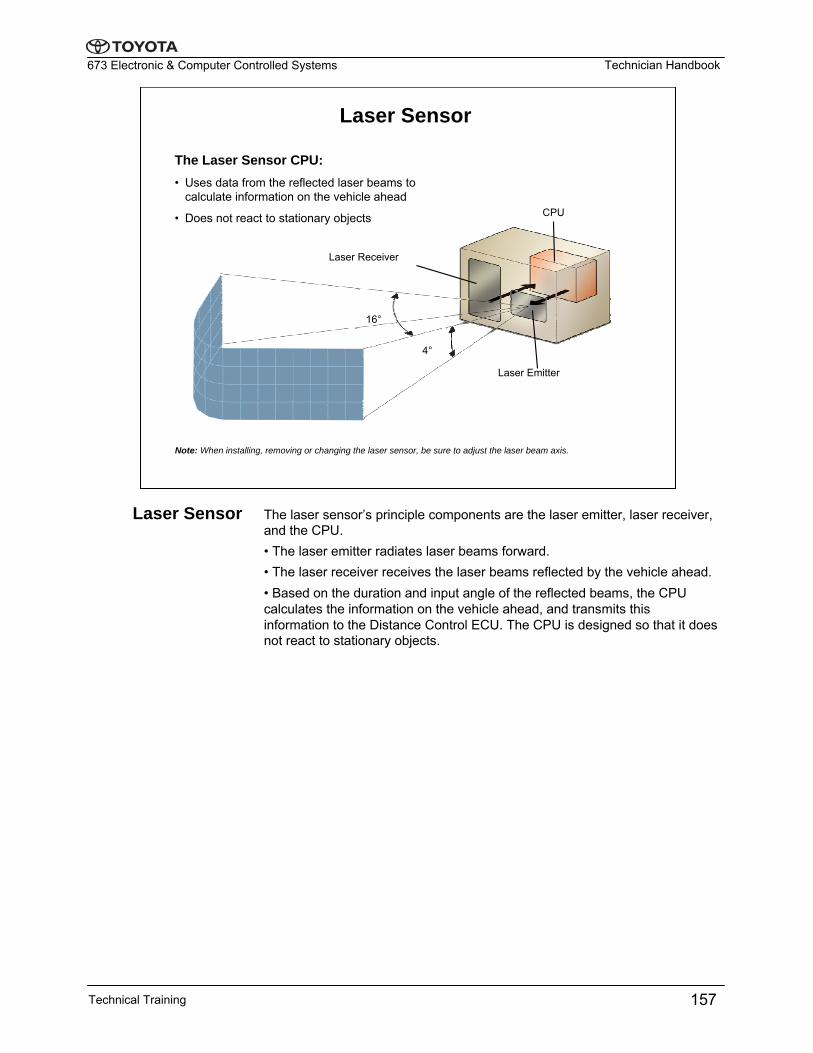
Laser Sensor
The Laser Sensor CPU:• Uses data from the reflected laser beams to
calculate information on the vehicle ahead
• Does not react to stationary objects
Note: When installing, removing or changing the laser sensor, be sure to adjust the laser beam axis.
CPU
Laser Emitter
16°
Laser Receiver
4°
The laser sensor’s principle components are the laser emitter, laser receiver, and the CPU.• The laser emitter radiates laser beams forward.• The laser receiver receives the laser beams reflected by the vehicle ahead.• Based on the duration and input angle of the reflected beams, the CPU calculates the information on the vehicle ahead, and transmits this information to the Distance Control ECU. The CPU is designed so that it does not react to stationary objects.
Laser Sensor
Technical Training 157
Technician Handbook673 Electronic & Computer Controlled Systems
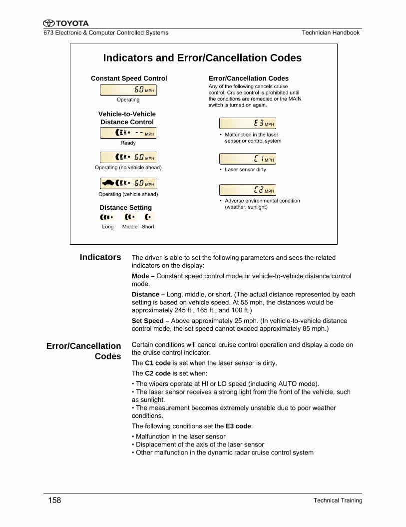
Indicators and Error/Cancellation Codes
Constant Speed Control
Operating
Vehicle-to-Vehicle Distance Control
Ready
Operating (no vehicle ahead)
Operating (vehicle ahead)
Error/Cancellation Codes Any of the following cancels cruise control. Cruise control is prohibited until the conditions are remedied or the MAIN switch is turned on again.
• Malfunction in the laser sensor or control system
• Laser sensor dirty
• Adverse environmental condition (weather, sunlight)Distance Setting
Long Middle Short
The driver is able to set the following parameters and sees the related indicators on the display:Mode – Constant speed control mode or vehicle-to-vehicle distance control mode.Distance – Long, middle, or short. (The actual distance represented by each setting is based on vehicle speed. At 55 mph, the distances would be approximately 245 ft., 165 ft., and 100 ft.) Set Speed – Above approximately 25 mph. (In vehicle-to-vehicle distance control mode, the set speed cannot exceed approximately 85 mph.)
Certain conditions will cancel cruise control operation and display a code on the cruise control indicator.The C1 code is set when the laser sensor is dirty.The C2 code is set when:• The wipers operate at HI or LO speed (including AUTO mode).• The laser sensor receives a strong light from the front of the vehicle, such as sunlight.• The measurement becomes extremely unstable due to poor weather conditions.The following conditions set the E3 code:• Malfunction in the laser sensor• Displacement of the axis of the laser sensor• Other malfunction in the dynamic radar cruise control system
Indicators
Error/Cancellation Codes
Technical Training158
Technician Handbook673 Electronic & Computer Controlled Systems
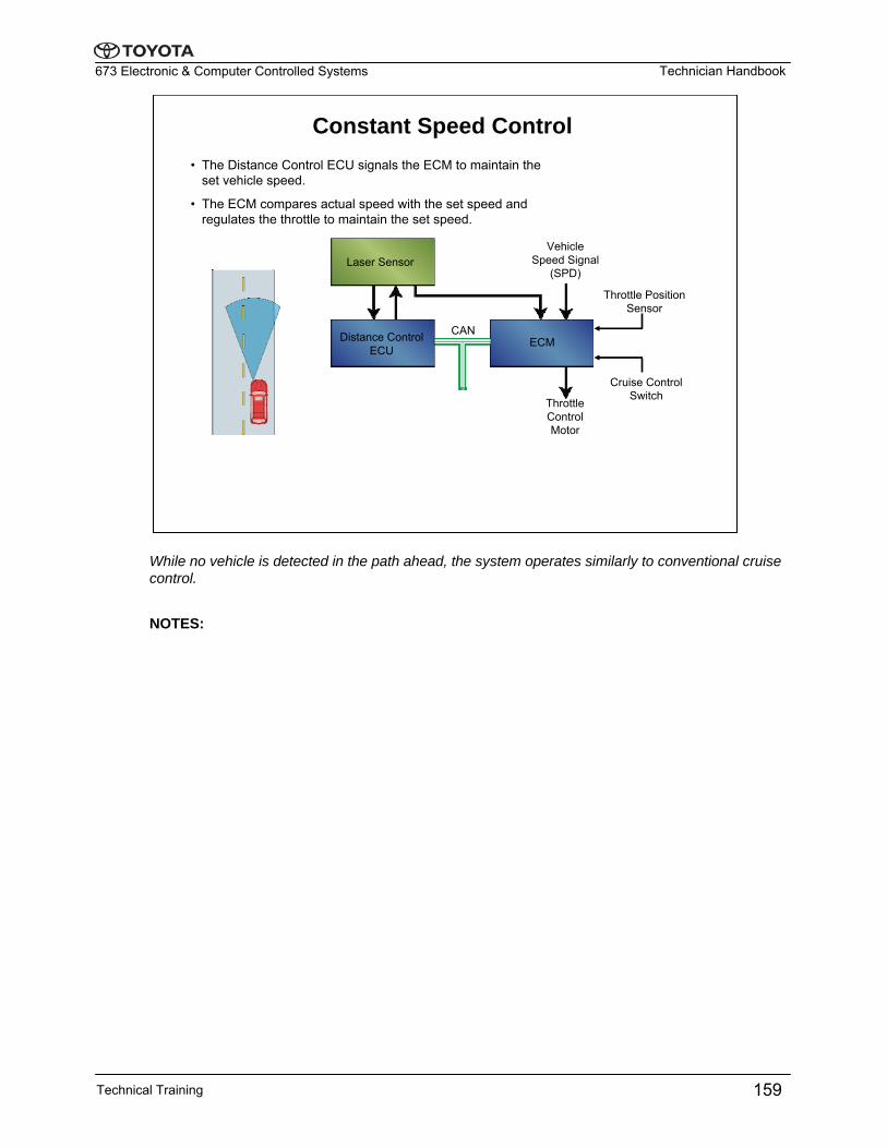
Constant Speed Control • The Distance Control ECU signals the ECM to maintain the
set vehicle speed.
• The ECM compares actual speed with the set speed and regulates the throttle to maintain the set speed.
Laser Sensor
Distance ControlECU
Vehicle Speed Signal
(SPD)
Cruise Control Switch
Throttle Position Sensor
Throttle Control Motor
ECMCAN
While no vehicle is detected in the path ahead, the system operates similarly to conventional cruise control.
NOTES:
Technical Training 159
Technician Handbook673 Electronic & Computer Controlled Systems
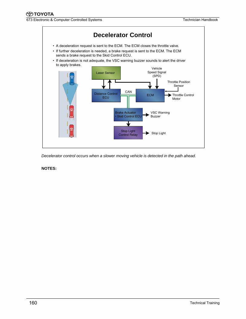
Decelerator Control • A deceleration request is sent to the ECM. The ECM closes the throttle valve.• If further deceleration is needed, a brake request is sent to the ECM. The ECM
sends a brake request to the Skid Control ECU.• If deceleration is not adequate, the VSC warning buzzer sounds to alert the driver
to apply brakes.
Laser Sensor
Distance ControlECU
Vehicle Speed Signal
(SPD)
Throttle Control Motor
ECM
Brake Actuator• Skid Control ECU
Stop Light Control Relay
VSC Warning Buzzer
Stop Light
CAN
Throttle Position Sensor
Decelerator control occurs when a slower moving vehicle is detected in the path ahead.
NOTES:
Technical Training160
Technician Handbook673 Electronic & Computer Controlled Systems
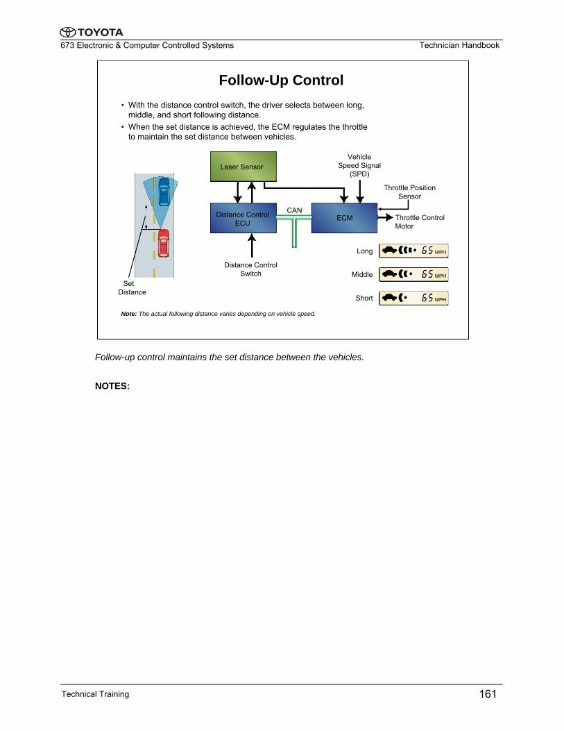
Follow-Up Control • With the distance control switch, the driver selects between long,
middle, and short following distance. • When the set distance is achieved, the ECM regulates the throttle
to maintain the set distance between vehicles.
Long
Middle
Short
Note: The actual following distance varies depending on vehicle speed.
Set Distance
Laser Sensor
Distance ControlECU
Vehicle Speed Signal
(SPD)
Distance Control Switch
ECM Throttle Control Motor
CAN
Throttle Position Sensor
Follow-up control maintains the set distance between the vehicles.
NOTES:
Technical Training 161
Technician Handbook673 Electronic & Computer Controlled Systems
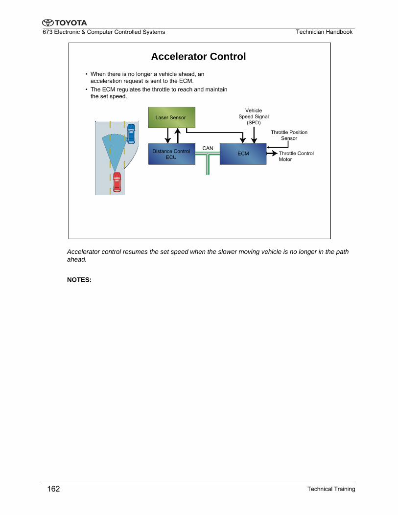
Accelerator Control • When there is no longer a vehicle ahead, an
acceleration request is sent to the ECM. • The ECM regulates the throttle to reach and maintain
the set speed.
Laser Sensor
Distance ControlECU
Vehicle Speed Signal
(SPD)
ECMCAN
Throttle Control Motor
Throttle Position Sensor
Accelerator control resumes the set speed when the slower moving vehicle is no longer in the path ahead.
NOTES:
Technical Training162
Technician Handbook673 Electronic & Computer Controlled Systems
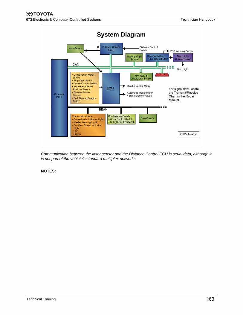
System Diagram
2005 Avalon
Laser Sensor Distance ControlECU
ECM
CAN
GatewayECU
• Combination Meter (SPD)
• Stop Light Switch• Cruise Control Switch• Accelerator Pedal Position Sensor
• Throttle Position Sensor
• Park/Neutral Position Switch
Steering Angle Sensor
Brake Actuator• Skid Control ECU
Yaw Rate & Decelerator Sensor
DLC3
Distance Control Switch VSC Warning Buzzer
Stop Light Control Relay
Stop Light
Throttle Control Motor
Automatic Transmission • Shift Solenoid Valves
BEAN
Combination Meter• Cruise MAIN Indicator Light• Master Warning Light• Constant Speed Indicator
Light• LCD• Buzzer
Combination Switch• Wiper Control Switch• Taillight Control Switch
Rain Sensor
For signal flow, locate the Transmit/Receive Chart in the Repair Manual.
Communication between the laser sensor and the Distance Control ECU is serial data, although it is not part of the vehicle’s standard multiplex networks.
NOTES:
Technical Training 163
Technician Handbook673 Electronic & Computer Controlled Systems
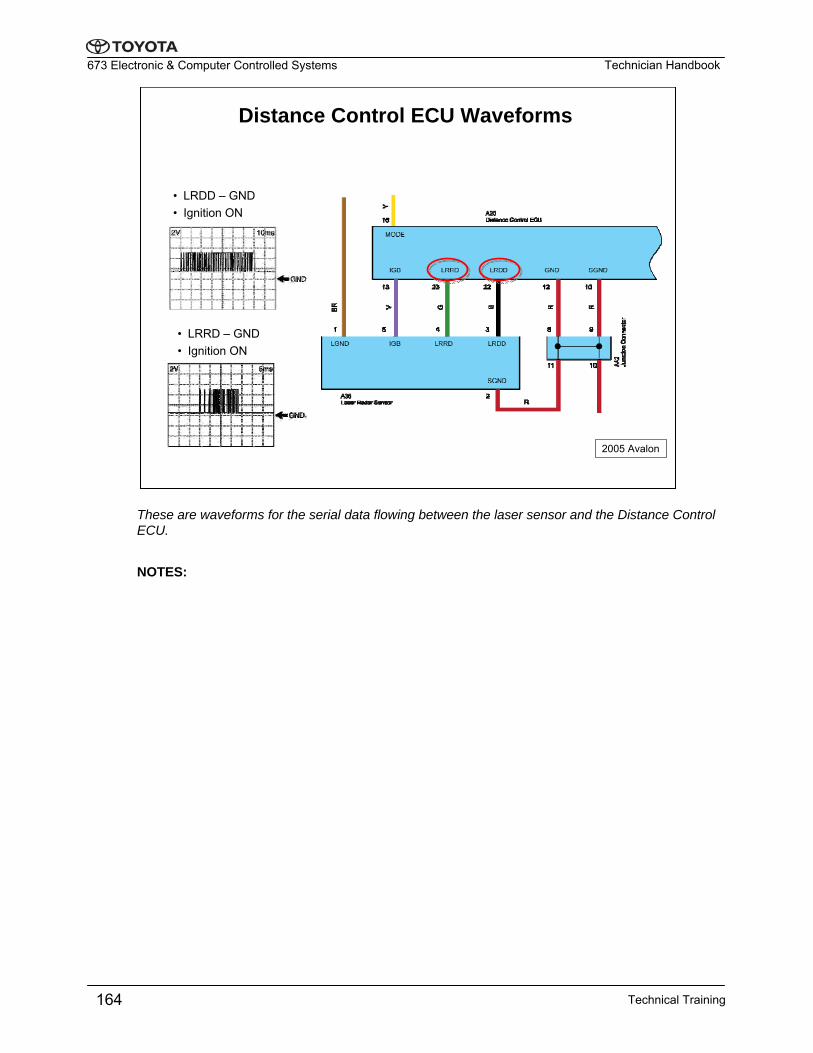
Distance Control ECU Waveforms
• LRDD – GND• Ignition ON
• LRRD – GND• Ignition ON
2005 Avalon
These are waveforms for the serial data flowing between the laser sensor and the Distance Control ECU.
NOTES:
Technical Training164
Technician Handbook673 Electronic & Computer Controlled Systems
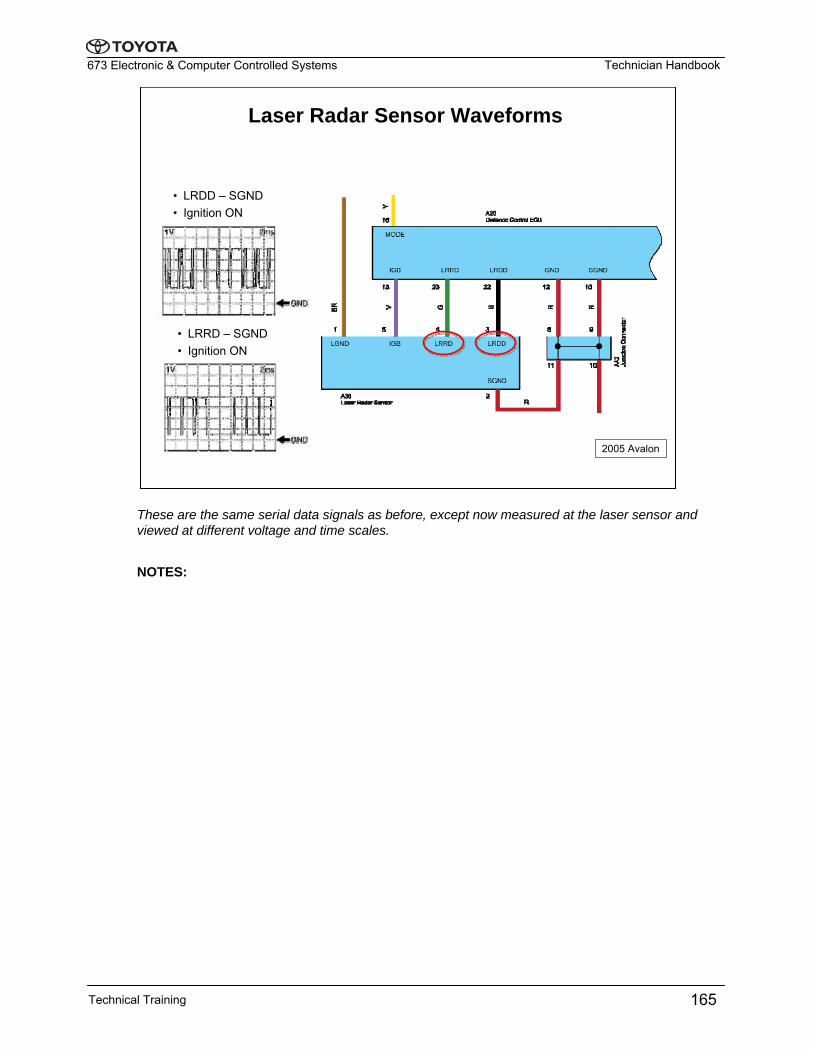
Laser Radar Sensor Waveforms
• LRDD – SGND• Ignition ON
• LRRD – SGND• Ignition ON
2005 Avalon
These are the same serial data signals as before, except now measured at the laser sensor and viewed at different voltage and time scales.
NOTES:
Technical Training 165
Technician Handbook673 Electronic & Computer Controlled Systems
Technical Training166
This Page Intentionally Left Blank


![Banco Products [I] Limitedbancoindia.com/pdf/cooling/TOYOTA.pdf · Banco Products [I] Limited ADAPTABLE FOR TOYOTA Vehicle F u e l ... COROLLA AE 81 - 1500 DX G 3A ... COROLLA VERSO](https://static.fdocuments.us/doc/165x107/5bab5a5709d3f22f738b82d5/banco-products-i-banco-products-i-limited-adaptable-for-toyota-vehicle-f.jpg)