Section 7 - Separation Equipment (.xlsx) - Home | GPA …€¦ · XLS file · Web view ·...
84
FIG. 7-1 Nomenclature A = MW = = NILL = = NLL = C' = Nref = D = Vessel diamter, ft = = Characteristic diameter in Stoke Number, St OD = = Liquid hydraulic diameter, ft P = = droplet diameter, ft = = Nozzel diamter, ft = = Droplet size (micron) for 95% removal = g = R = GOR = Gas-oil ratio Re = H = Height, ft Stk = = Settling height, ft T = HILL = High interphase liquid level t = HHILL = High- high interphase liquid level V = HLL = High liquid level = HHLL = High- high liquid level = J = = K = empirical constant for separator sizing, ft/sec = = = L = seam to seam length of vessel, ft = = = LILL = Low interphase liquid level = LLILL = Low-low interphase liquid level Z = LLL = Low liquid level Greek LLLL = Low-low liquid level β = = mass of droplet or particle, lb = = = = = area, ft 2 Amesh Mesh pad area, ft 2 Ap particle or droplet cross sectional area, ft 2 drag coefficient of particle, dimensionless Nμ Dc Dh Dp QA d2 Q1 d95 Q1,max acceleration due to gravity, 32.2 ft/sec 2 Hset Vc Vh gas momentum, lb/(ft•sec 2 ) V1 Vr KCR proportionality constant from Fig. 7-4 for use in Eq 7-5, dimensionless Vr,max Vt Lset Effective gravity droplet settling length for a horizontal separator, ft Wg W1 Mp ρc ρg ρl ρhl ρll
Transcript of Section 7 - Separation Equipment (.xlsx) - Home | GPA …€¦ · XLS file · Web view ·...

FIG. 7-1Nomenclature
A = MW =
= NILL =
= NLL =
C' = drag coefficient of particle, dimensionless (Fig. 7-3) Nref =D = Vessel diamter, ft =
= Characteristic diameter in Stoke Number, St OD == Liquid hydraulic diameter, ft P == droplet diameter, ft =
= Nozzel diamter, ft == Droplet size (micron) for 95% removal =
g = R =
GOR = Gas-oil ratio Re =
H = Height, ft Stk =
= Settling height, ft T =HILL = High interphase liquid level t =HHILL = High- high interphase liquid level V =HLL = High liquid level =HHLL = High- high liquid level =
J = =
K = empirical constant for separator sizing, ft/sec == =
L = seam to seam length of vessel, ft =
= =
LILL = Low interphase liquid level =LLILL = Low-low interphase liquid level Z =LLL = Low liquid level GreekLLLL = Low-low liquid level
β =
= mass of droplet or particle, lb ==
=
=
=
area, ft2
Amesh Mesh pad area, ft2
Ap particle or droplet cross sectional area, ft2
Nμ
Dc
Dh
Dp QA
d2 Q1
d95 Q1,max
acceleration due to gravity, 32.2 ft/sec2
Hset
Vc
Vh
gas momentum, lb/(ft•sec2) V1
Vr
KCR proportionality constant from Fig. 7-4 for use in Eq 7-5, dimensionless
Vr,max
Vt
Lset Effective gravity droplet settling length for a horizontal separator, ft
Wg
W1
Mp ρc
ρg
ρl
ρhl
ρll

===
==
==
σ =φ =
The sample calculations, equations and spreadsheets presented herein were developed using examples published in the Engineering Data Book as published by the Gas Processor Suppliers Association as a service to the gas processing industry. All information and calculation formulae has been compiled and edited in cooperation with Gas Processors Association (GPA).While every effort has been made to present accurate and reliable technical information and calculation spreadsheets based on the GPSA Engineering Data Book sample calculations, the use of such information is voluntary and the GPA and GPSA do not guarantee the accuracy, completeness, efficacy or timeliness of such information. Reference herein to any specific commercial product, calculation method, process, or service by trade-name, trademark, and service mark manufacturer or otherwise does not constitute or imply endorsement, recommendation or favoring by the GPA and/or GPSA.
The Calculation Spreadsheets are provided without warranty of any kind including warranties of accuracy or reasonableness of factual or scientific assumptions, studies or conclusions, or merchantability, fitness for a particular purpose or non-infringement of intellectual property.In no event will the GPA or GPSA and their members be liable for any damages whatsoever (including without limitation, those resulting from lost profits, lost data or business interruption) arising from the use, inability to , reference to or reliance on the information in thes Publication, whether based on warranty, contract, tort or any other legal theory and whether or not advised of the possibility of such damages.These calculation spreadsheets are provided to provide an “Operational level” of accuracy calculation based on rather broad assumptions (including but not limited to; temperatures, pressures, compositions, imperial curves, site conditions etc) and do not replace detailed and accurate Design Engineering taking into account actual process conditions, fluid properties, equipment condition or fowling and actual control set-point dead-band limitations.
ρm
ρp
μc
μg
μhl
μll
μ1

FIG. 7-1Nomenclature
molecular weight, lb/lb mole
Normal interphase liquid level
Normal liquid level
Reynolds film numberInterfacial viscosity numberOutside diamter, insystem pressure, psia
Reynolds number, dimensionless
retention time, minutesVelocity, ft/secVelocity of continuous phase, ft/sec
Liquid velocity, ft/sec
Gas velocity relative to liquid, ft/sec
Flow rate of gas, lb/hr
Flow rate of liquid, lb/hrcompressibility factor, dimensionless
Greek
actual gas flow rate, ft3/sec
Liquid volumetric flow rate, ft3/minMaximum liquid volumetric flow rate, ft3/min
gas constant, 10.73 (psia•ft3)(°R•lb mole)
Dimensionless Stokes Number: [g • pc • Vc • D2p]/(18μc • Dc)
system temperature, °R
Flow vapor velocity between gas-liquid interphase and the top of a horizontal separator, ft/sec
Maximum velocity of a gas relative to liquid to resist substantial re-entreainment
critical or terminal gas velocity necessary for particles of size Dp to drop or settle out of gas, ft/sec
Ratio of the number of influent particles of a given size to the number of effluent particles of the same size
Continuous phase density, lb/ft3
gas phase density, lb/ft3
liquid phase density, droplet or particle, lb/ft3
Heavy liquid phase density, lb/ft3
Light liquid phase density, lb/ft3

viscosity of continuous pase, Cp
Gas viscosity, cPHeavy liquid phase viscosity, cP
Light liquid phase viscosity, cPLiquid viscosity, cPLiquid surface tension, dynes/cmFlow parameter
The sample calculations, equations and spreadsheets presented herein were developed using examples published in the Engineering Data Book as published by the Gas Processor Suppliers Association as a service to the gas processing industry. All information and calculation formulae has been compiled and edited in cooperation with Gas Processors Association (GPA).While every effort has been made to present accurate and reliable technical information and calculation spreadsheets based on the GPSA Engineering Data Book sample calculations, the use of such information is voluntary and the GPA and GPSA do not guarantee the accuracy, completeness, efficacy or timeliness of such information. Reference herein to any specific commercial product, calculation method, process, or service by trade-name, trademark, and service mark manufacturer or otherwise does not constitute or imply endorsement, recommendation or favoring by the GPA and/or GPSA.
The Calculation Spreadsheets are provided without warranty of any kind including warranties of accuracy or reasonableness of factual or scientific assumptions, studies or conclusions, or merchantability, fitness for a particular purpose or non-infringement of intellectual property.In no event will the GPA or GPSA and their members be liable for any damages whatsoever (including without limitation, those resulting from lost profits, lost data or business interruption) arising from the use, inability to , reference to or reliance on the information in thes Publication, whether based on warranty, contract, tort or any other legal theory and whether or not advised of the possibility of such damages.These calculation spreadsheets are provided to provide an “Operational level” of accuracy calculation based on rather broad assumptions (including but not limited to; temperatures, pressures, compositions, imperial curves, site conditions etc) and do not replace detailed and accurate Design Engineering taking into account actual process conditions, fluid properties, equipment condition or fowling and actual control set-point dead-band limitations.
Mixed fluid density, lb/ft3
Droplet or partical phase density, lb/ft3

The sample calculations, equations and spreadsheets presented herein were developed using examples published in the Engineering Data Book as published by the Gas Processor Suppliers Association as a service to the gas processing industry. All information and calculation formulae has been compiled and edited in cooperation with Gas Processors Association (GPA).While every effort has been made to present accurate and reliable technical information and calculation spreadsheets based on the GPSA Engineering Data Book sample calculations, the use of such information is voluntary and the GPA and GPSA do not guarantee the accuracy, completeness, efficacy or timeliness of such information. Reference herein to any specific commercial product, calculation method, process, or service by trade-name, trademark, and service mark manufacturer or otherwise does not constitute or imply endorsement, recommendation or favoring by the GPA and/or GPSA.
The Calculation Spreadsheets are provided without warranty of any kind including warranties of accuracy or reasonableness of factual or scientific assumptions, studies or conclusions, or merchantability, fitness for a particular purpose or non-infringement of intellectual property.In no event will the GPA or GPSA and their members be liable for any damages whatsoever (including without limitation, those resulting from lost profits, lost data or business interruption) arising from the use, inability to , reference to or reliance on the information in thes Publication, whether based on warranty, contract, tort or any other legal theory and whether or not advised of the possibility of such damages.These calculation spreadsheets are provided to provide an “Operational level” of accuracy calculation based on rather broad assumptions (including but not limited to; temperatures, pressures, compositions, imperial curves, site conditions etc) and do not replace detailed and accurate Design Engineering taking into account actual process conditions, fluid properties, equipment condition or fowling and actual control set-point dead-band limitations.

The sample calculations, equations and spreadsheets presented herein were developed using examples published in the Engineering Data Book as published by the Gas Processor Suppliers Association as a service to the gas processing industry. All information and calculation formulae has been compiled and edited in cooperation with Gas Processors Association (GPA).While every effort has been made to present accurate and reliable technical information and calculation spreadsheets based on the GPSA Engineering Data Book sample calculations, the use of such information is voluntary and the GPA and GPSA do not guarantee the accuracy, completeness, efficacy or timeliness of such information. Reference herein to any specific commercial product, calculation method, process, or service by trade-name, trademark, and service mark manufacturer or otherwise does not constitute or imply endorsement, recommendation or favoring by the GPA and/or GPSA.
In no event will the GPA or GPSA and their members be liable for any damages whatsoever (including without limitation, those resulting from lost profits, lost data or business interruption) arising from the use, inability to , reference to or reliance on the information in thes Publication, whether based on warranty, contract, tort or any other legal theory and whether or not advised of the possibility of such damages.These calculation spreadsheets are provided to provide an “Operational level” of accuracy calculation based on rather broad assumptions (including but not limited to; temperatures, pressures, compositions, imperial curves, site conditions etc) and do not replace detailed and accurate Design Engineering taking into account actual process conditions, fluid properties, equipment condition or fowling and actual control set-point dead-band limitations.

While every effort has been made to present accurate and reliable technical information and calculation spreadsheets based on the GPSA Engineering Data Book sample calculations, the use of such information is voluntary and the GPA and GPSA do not guarantee the accuracy, completeness, efficacy or timeliness of such information. Reference herein to any specific commercial product, calculation method, process, or service by trade-name, trademark, and service mark manufacturer or otherwise does not constitute or imply endorsement, recommendation or favoring by the GPA and/or GPSA.
These calculation spreadsheets are provided to provide an “Operational level” of accuracy calculation based on rather broad assumptions (including but not limited to; temperatures, pressures, compositions, imperial curves, site conditions etc) and do not replace detailed and accurate Design Engineering taking into account actual process conditions, fluid properties, equipment condition or fowling and actual control set-point dead-band limitations.

While every effort has been made to present accurate and reliable technical information and calculation spreadsheets based on the GPSA Engineering Data Book sample calculations, the use of such information is voluntary and the GPA and GPSA do not guarantee the accuracy, completeness, efficacy or timeliness of such information. Reference herein to any specific commercial product, calculation method, process, or service by trade-name, trademark, and service mark manufacturer or otherwise does not constitute or imply endorsement, recommendation or favoring by the GPA and/or GPSA.

Phsical Properties = 2.07 = 0.012 cP= 31.2
= .000492 ft
From Equation 7-4,
= 4741
From Fig. 7-5, Drag coefficient, C' = 1.4
Terminal Velocity,
= 0.46 ft/sec(3 • 2.07 • 1.4)
The sample calculations, equations and spreadsheets presented herein were developed using examples published in the Engineering Data Book as published by the Gas Processor Suppliers Association as a service to the gas processing industry. All information and calculation formulae has been compiled and edited in cooperation with Gas Processors Association (GPA).While every effort has been made to present accurate and reliable technical information and calculation spreadsheets based on the GPSA Engineering Data Book sample calculations, the use of such information is voluntary and the GPA and GPSA do not guarantee the accuracy, completeness, efficacy or timeliness of such information. Reference herein to any specific commercial product, calculation method, process, or service by trade-name, trademark, and service mark manufacturer or otherwise does not constitute or imply endorsement, recommendation or favoring by the GPA and/or GPSA.The Calculation Spreadsheets are provided without warranty of any kind including warranties of accuracy or reasonableness of factual or scientific assumptions, studies or conclusions, or merchantability, fitness for a particular purpose or non-infringement of intellectual property.In no event will the GPA or GPSA and their members be liable for any damages whatsoever (including without limitation, those resulting from lost profits, lost data or business interruption) arising from the use, inability to , reference to or reliance on the information in thes Publication, whether based on warranty, contract, tort or any other legal theory and whether or not advised of the possibility of such damages.These calculation spreadsheets are provided to provide an “Operational level” of accuracy calculation based on rather broad assumptions (including but not limited to; temperatures, pressures, compositions, imperial curves, site conditions etc) and do not replace detailed and accurate Design Engineering taking into account actual process conditions, fluid properties, equipment condition or fowling and actual control set-point dead-band limitations.
Example 7-1 -- Calculate the terminal velocity using the drag coefficient and Stokes' Law terminal settling velocity in a vertical gas-liquid separator for a 150 micron particle for a fluid with the physical properties listed below.
ρg lb/ft3
μg
ρl lb/ft3
Particle Diameter, Dp = (150 • 0.00003937)/(12)
C' (Re) 2 = ((0.95) • (10)8 • (2.07) • (0.000492)3 • (31.2 - 2.07))/(0.012)2
Vt = (4 • 32.2 • 0.000492 • (31.2 - 2.07)) 0.5[( )/( )]

Phsical Properties = 2.07 = 0.012= 31.2= 150
=
From Equation 7-4,
= 4741
From Fig. 7-5, Drag coefficient, C' = 1.4
Terminal Velocity,
(3 • 2.07 • 1.4)
The sample calculations, equations and spreadsheets presented herein were developed using examples published in the Engineering Data Book as published by the Gas Processor Suppliers Association as a service to the gas processing industry. All information and calculation formulae has been compiled and edited in cooperation with Gas Processors Association (GPA).While every effort has been made to present accurate and reliable technical information and calculation spreadsheets based on the GPSA Engineering Data Book sample calculations, the use of such information is voluntary and the GPA and GPSA do not guarantee the accuracy, completeness, efficacy or timeliness of such information. Reference herein to any specific commercial product, calculation method, process, or service by trade-name, trademark, and service mark manufacturer or otherwise does not constitute or imply endorsement, recommendation or favoring by the GPA and/or GPSA.The Calculation Spreadsheets are provided without warranty of any kind including warranties of accuracy or reasonableness of factual or scientific assumptions, studies or conclusions, or merchantability, fitness for a particular purpose or non-infringement of intellectual property.In no event will the GPA or GPSA and their members be liable for any damages whatsoever (including without limitation, those resulting from lost profits, lost data or business interruption) arising from the use, inability to , reference to or reliance on the information in thes Publication, whether based on warranty, contract, tort or any other legal theory and whether or not advised of the possibility of such damages.These calculation spreadsheets are provided to provide an “Operational level” of accuracy calculation based on rather broad assumptions (including but not limited to; temperatures, pressures, compositions, imperial curves, site conditions etc) and do not replace detailed and accurate Design Engineering taking into account actual process conditions, fluid properties, equipment condition or fowling and actual control set-point dead-band limitations.
Application 7-1 -- Calculate the terminal velocity using the drag coefficient and Stokes' Law terminal settling velocity in a vertical gas-liquid separator for a 150 micron particle for a fluid with the physical properties listed below.
ρg
μg
ρl
Dp
Particle Diameter, Dp = (150 • 0.00003937)/(12)
C' (Re) 2 = ((0.95) • (10)8 • (2.07) • (0.000492)3 • (31.2 - 2.07))/(0.012)2
Vt = (4 • 32.2 • 0.000492 • (31.2 - 2.07)) 0.5[( )/( )]

cP
microns0.000492 ft
= 0.46 ft/sec
The sample calculations, equations and spreadsheets presented herein were developed using examples published in the Engineering Data Book as published by the Gas Processor Suppliers Association as a service to the gas processing industry. All information and calculation formulae has been compiled and edited in cooperation with Gas Processors Association (GPA).While every effort has been made to present accurate and reliable technical information and calculation spreadsheets based on the GPSA Engineering Data Book sample calculations, the use of such information is voluntary and the GPA and GPSA do not guarantee the accuracy, completeness, efficacy or timeliness of such information. Reference herein to any specific commercial product, calculation method, process, or service by trade-name, trademark, and service mark manufacturer or otherwise does not constitute or imply endorsement, recommendation or favoring by the GPA and/or GPSA.The Calculation Spreadsheets are provided without warranty of any kind including warranties of accuracy or reasonableness of factual or scientific assumptions, studies or conclusions, or merchantability, fitness for a particular purpose or non-infringement of intellectual property.In no event will the GPA or GPSA and their members be liable for any damages whatsoever (including without limitation, those resulting from lost profits, lost data or business interruption) arising from the use, inability to , reference to or reliance on the information in thes Publication, whether based on warranty, contract, tort or any other legal theory and whether or not advised of the possibility of such damages.These calculation spreadsheets are provided to provide an “Operational level” of accuracy calculation based on rather broad assumptions (including but not limited to; temperatures, pressures, compositions, imperial curves, site conditions etc) and do not replace detailed and accurate Design Engineering taking into account actual process conditions, fluid properties, equipment condition or fowling and actual control set-point dead-band limitations.
-- Calculate the terminal velocity using the drag coefficient and Stokes' Law terminal settling velocity in a vertical gas-liquid separator for a 150 micron particle for a fluid with the physical
lb/ft3
lb/ft3

The sample calculations, equations and spreadsheets presented herein were developed using examples published in the Engineering Data Book as published by the Gas Processor Suppliers Association as a service to the gas processing industry. All information and calculation formulae has been compiled and edited in cooperation with Gas Processors Association (GPA).While every effort has been made to present accurate and reliable technical information and calculation spreadsheets based on the GPSA Engineering Data Book sample calculations, the use of such information is voluntary and the GPA and GPSA do not guarantee the accuracy, completeness, efficacy or timeliness of such information. Reference herein to any specific commercial product, calculation method, process, or service by trade-name, trademark, and service mark manufacturer or otherwise does not constitute or imply endorsement, recommendation or favoring by the GPA and/or GPSA.
In no event will the GPA or GPSA and their members be liable for any damages whatsoever (including without limitation, those resulting from lost profits, lost data or business interruption) arising from the use, inability to , reference to or reliance on the information in thes Publication, whether based on warranty, contract, tort or any other legal theory and whether or not advised of the possibility of such damages.These calculation spreadsheets are provided to provide an “Operational level” of accuracy calculation based on rather broad assumptions (including but not limited to; temperatures, pressures, compositions, imperial curves, site conditions etc) and do not replace detailed and accurate Design Engineering taking into account actual process conditions, fluid properties, equipment condition or fowling and actual control set-point dead-band limitations.

While every effort has been made to present accurate and reliable technical information and calculation spreadsheets based on the GPSA Engineering Data Book sample calculations, the use of such information is voluntary and the GPA and GPSA do not guarantee the accuracy, completeness, efficacy or timeliness of such information. Reference herein to any specific commercial product, calculation method, process, or service by trade-name, trademark, and service mark manufacturer or otherwise does not constitute or imply endorsement, recommendation or favoring by the GPA and/or GPSA.
These calculation spreadsheets are provided to provide an “Operational level” of accuracy calculation based on rather broad assumptions (including but not limited to; temperatures, pressures, compositions, imperial curves, site conditions etc) and do not replace detailed and accurate Design Engineering taking into account actual process conditions, fluid properties, equipment condition or fowling and actual control set-point dead-band limitations.

While every effort has been made to present accurate and reliable technical information and calculation spreadsheets based on the GPSA Engineering Data Book sample calculations, the use of such information is voluntary and the GPA and GPSA do not guarantee the accuracy, completeness, efficacy or timeliness of such information. Reference herein to any specific commercial product, calculation method, process, or service by trade-name, trademark, and service mark manufacturer or otherwise does not constitute or imply endorsement, recommendation or favoring by the GPA and/or GPSA.

Operating temperature = 120 °FOperating pressure = 500 psig
Gas flowrate = 150 MMSCFD(289,200 lb/hr)Liquid flowrate = 100 gpm (35,850 lb/hr)
Design Factor = %
= 1.552 = 0.013 cP= 0.574 cP= 1.75= 44.68
LLLL to LL = 1 min, LLL to HLL = 5 min, HLL to HHLL = 1 min
High efficiency wire mesh mist eliminatorDiffuser inlet device for high gas rate with significant liquids
= 289200
= 56.94K = 0.35 ft/sec for a high efficiency mist eliminator at low pressure
K is corrected for pressure using Fig. 7-36 K= 0.2860
= 0.286* 44.68 1.552
1.552= 1.51 ft/sec (Equation 7-11)
A = (56.94ft/sec)/(1.51ft/sec)
37.7
Example 7-2 -- Determine the size of a vertical gas-liquid separator with a high efficiency wire mesh mist eliminator to handle 150 MMSCFD (MW= 17.55) of gas and 100 gpm of condensate. A design factor of 10% will be used.
Operating Conditions --
Physical Properties --
ρg lb/ft3
μg
μl
ρm lb/ft3
ρl lb/ft3
Project Surge Times for this Application --
Internals Selected --
Vessel Diamter Sizing --
QA lb/hr • 1/1.552lb/ft3 • 1hr/3600sec • 1.1
ft3/sec
Vmax
Vmax
ft2
√(( ( )/ )/( ))

D = + 0.33 ft
0.33 ft added for support ring and then rounded to nearest half foot
D = 7.5 ft
A = 44.2
Q = 35850
= 14.71H1 (Bottom tangent to LALL) = 18 in. ot allow level bridle taps above tangent.
LLL to HLL
20
LLLL to LLL, and HLL to HHLL
4
H2 = 4 + 20 + 4 = 28 in = 2.333 ft, use 2.5
Check De-Gassing (200 micron bubble)
Using Equation 7-16a:
0.00555
Using Equation 7-17:
0.086
Inlet Piping is 18 in Sch. 40 (ID = 16.876 in.), based on acceptable line sizing criteria.
Assuming the inlet nozzle is the same size as piping, check that the inlet volocity satisfies allowable limits.
V =(289,200 + 35850) lb/hr • 144 in2 • 1hr
= 33.2 ft/sec
4 • 56.94ft3/sec ≥ 7.26 ftπ • 1.51 ft/sec
Actual dimensions --
ft2
Liquid Surge Section --
lb/hr •(1/44.86lb/ft3) • (1hr/60min) • 1.1
ft3/min
(14.71ft3/min)/44.2ft2 • 5 min = 1.66ft = 19.97 in, use
(14.71ft3/min)/44.2ft2 • 1 min = 0.33ft = 3.99 in, use
Vl = (14.71 ft3/min)/44.2ft2 • 1min/60sec =
Vt = 1.145 • 10-3 • ((44.68lb/ft3) - (1.552lb/ft3))/0.574 =
As Vl < Vt for a 200 micron bubble, de-gassing of 200 micron particles can occur
Check Inlet Velocity Head --
1.75 lb/ft3 • 1ft2π (16.876/2)2 in2 • 3600 sec
√(□(64&■8( @ )/( )))
/( )

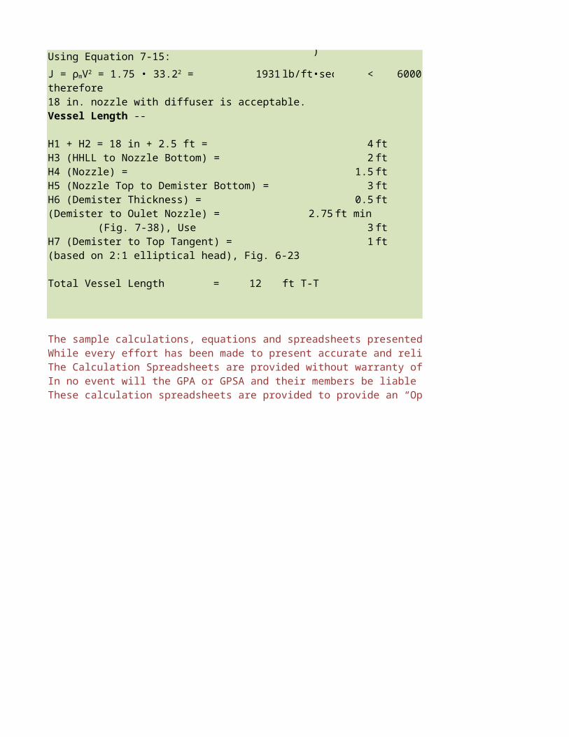
Using Equation 7-15:
1931 < 6000therefore18 in. nozzle with diffuser is acceptable.
H1 + H2 = 18 in + 2.5 ft = 4 ftH3 (HHLL to Nozzle Bottom) = 2 ftH4 (Nozzle) = 1.5 ftH5 (Nozzle Top to Demister Bottom) = 3 ftH6 (Demister Thickness) = 0.5 ft(Demister to Oulet Nozzle) = 2.75 ft min
(Fig. 7-38), Use 3 ftH7 (Demister to Top Tangent) = 1 ft(based on 2:1 elliptical head), Fig. 6-23
Total Vessel Length = 12 ft T-T
The sample calculations, equations and spreadsheets presented herein were developed using examples published in the Engineering Data Book as published by the Gas Processor Suppliers Association as a service to the gas processing industry. All information and calculation formulae has been compiled and edited in cooperation with Gas Processors Association (GPA).While every effort has been made to present accurate and reliable technical information and calculation spreadsheets based on the GPSA Engineering Data Book sample calculations, the use of such information is voluntary and the GPA and GPSA do not guarantee the accuracy, completeness, efficacy or timeliness of such information. Reference herein to any specific commercial product, calculation method, process, or service by trade-name, trademark, and service mark manufacturer or otherwise does not constitute or imply endorsement, recommendation or favoring by the GPA and/or GPSA.The Calculation Spreadsheets are provided without warranty of any kind including warranties of accuracy or reasonableness of factual or scientific assumptions, studies or conclusions, or merchantability, fitness for a particular purpose or non-infringement of intellectual property.In no event will the GPA or GPSA and their members be liable for any damages whatsoever (including without limitation, those resulting from lost profits, lost data or business interruption) arising from the use, inability to , reference to or reliance on the information in thes Publication, whether based on warranty, contract, tort or any other legal theory and whether or not advised of the possibility of such damages.These calculation spreadsheets are provided to provide an “Operational level” of accuracy calculation based on rather broad assumptions (including but not limited to; temperatures, pressures, compositions, imperial curves, site conditions etc) and do not replace detailed and accurate Design Engineering taking into account actual process conditions, fluid properties, equipment condition or fowling and actual control set-point dead-band limitations.
J = ρmV2 = 1.75 • 33.22 = lb/ft•sec2
Vessel Length --

Operating temperature = 120 °FOperating pressure = 500 psig
Gas flowrate = 289,200 lb/hrLiquid flowrate = 100 gpm
Design Factor = 10 %
= 1.552 = 0.013 cP= 0.574 2013GPA= 1.75
ρl = 44.68
LLLL to LL = 1 min, LLL to HLL = 5 min, HLL to HHLL = 1 min
High efficiency wire mesh mist eliminatorDiffuser inlet device for high gas rate with significant liquids
= 289,200
= 56.94for a high efficiency mist eliminator at low pressure K = 0.35 ft/sec
K is corrected for pressure using Fig. 7-36
= 0.286* 44.68 1.552
1.552= 1.51 ft/sec
A = (56.94ft/sec)/(1.51ft/sec)
37.8
-- Determine the size of a vertical gas-liquid separator with a high efficiency wire mesh mist eliminator to handle 150 MMSCFD (MW= 17.55) of gas and 100 gpm of condensate. A design factor of 10% will be used.
Application 7-2 -- Determine the size of a vertical gas-liquid separator with a high efficiency wire mesh mist eliminator to handle 150 MMSCFD (MW= 17.55) of gas and 100 gpm of condensate. A design factor of 10% will be used.
Operating Conditions --
Physical Properties --
ρg lb/ft3
μg
μl
ρm lb/ft3
lb/ft3
Project Surge Times for this Application --
Internals Selected --
Vessel Diamter Sizing --
lb/hr • 1/1.552lb/ft3 • 1hr/3600sec • 1.1 QA
ft3/sec
Vmax
Vmax
ft2
√(( ( )/ )/( ))

(Equation 7-18) D = +0.33 =
0.33 ft added for support ring and then rounded to nearest half foot 0.33 ft added for support ring and then rounded to nearest half foot
D = 7.5 ft
A = 44.2
Q = 35,850
= 14.7101611H1 (Bottom tangent to LALL) = 18 in. ot allow level bridle taps above tangent. H1 (Bottom tangent to LALL) = 18 in. ot allow level bridle taps above tangent.
LLL to HLL
in 19.98
LLLL to LLL, and HLL to HHLL
in 4.00
ft H2 = 4 + 20 + 4 = 28 in = 2.33
Check De-Gassing (200 micron bubble)
Using Equation 7-16a:
ft/sec
Using Equation 7-17:
ft/sec
Inlet Piping is 18 in Sch. 40 (ID = 16.876 in.), based on acceptable line sizing criteria. Inlet Piping is 18 in Sch. 40 (ID = 16.876
Assuming the inlet nozzle is the same size as piping, check that the inlet volocity satisfies allowable limits. Assuming the inlet nozzle is the same size as piping, check that the inlet volocity satisfies allowable limits.
(289,200 + 35850) lb/hr • 144 in2 • 1hrV =
(289,200 + 35850) lb/hr • 144 in2 • 1hr
= 33.2 ft/sec
4 • 56.94ft3/secπ • 1.51 ft/sec
Actual dimensions --
ft2
Liquid Surge Section --
lb/hr •(1/44.86lb/ft3) • (1hr/60min) • 1.1 lb/hr •(1/44.86lb/ft3) • (1hr/60min) • 1.1
ft3/min
(14.71ft3/min)/44.2ft2 • 5 min = 1.66ft =
(14.71ft3/min)/44.2ft2 • 1 min =
Vl = (14.71 ft3/min)/44.2ft2 • 1min/60sec =
Vt = 1.145 • 10-3 • (44.68lb/ft3 - 1.552lb/ft3)/0.574 =
for a 200 micron bubble, de-gassing of 200 micron particles can occur As Vl < Vt for a 200 micron bubble, de-gassing of 200 micron particles can occur
Check Inlet Velocity Head --
π (16.876/2)2 in2 • 3600 sec 1.75 lb/ft3 • 1ft2π (16.876/2)2 in2 • 3600 sec /( )
√(□(64&■8( @ )/( )))
/( )

Using Equation 7-15:
1931therefore18 in. nozzle with diffuser is acceptable.
H1 + H2 = 18 in + 2.5 ft =(for diffuser) H3 (HHLL to Nozzle Bottom) =
H4 (Nozzle) =H5 (Nozzle Top to Demister Bottom) =H6 (Demister Thickness) = (Demister to Oulet Nozzle) = 2.75
(Fig. 7-38), Use H7 (Demister to Top Tangent) =(based on 2:1 elliptical head), Fig. 6-23
Total Vessel Length = 12 ft T-T
The sample calculations, equations and spreadsheets presented herein were developed using examples published in the Engineering Data Book as published by the Gas Processor Suppliers Association as a service to the gas processing industry. All information and calculation formulae has been compiled and edited in cooperation with Gas Processors Association (GPA).While every effort has been made to present accurate and reliable technical information and calculation spreadsheets based on the GPSA Engineering Data Book sample calculations, the use of such information is voluntary and the GPA and GPSA do not guarantee the accuracy, completeness, efficacy or timeliness of such information. Reference herein to any specific commercial product, calculation method, process, or service by trade-name, trademark, and service mark manufacturer or otherwise does not constitute or imply endorsement, recommendation or favoring by the GPA and/or GPSA.The Calculation Spreadsheets are provided without warranty of any kind including warranties of accuracy or reasonableness of factual or scientific assumptions, studies or conclusions, or merchantability, fitness for a particular purpose or non-infringement of intellectual property.In no event will the GPA or GPSA and their members be liable for any damages whatsoever (including without limitation, those resulting from lost profits, lost data or business interruption) arising from the use, inability to , reference to or reliance on the information in thes Publication, whether based on warranty, contract, tort or any other legal theory and whether or not advised of the possibility of such damages.These calculation spreadsheets are provided to provide an “Operational level” of accuracy calculation based on rather broad assumptions (including but not limited to; temperatures, pressures, compositions, imperial curves, site conditions etc) and do not replace detailed and accurate Design Engineering taking into account actual process conditions, fluid properties, equipment condition or fowling and actual control set-point dead-band limitations.
lb/ft•sec2 J = ρmV2 = 1.75 • 33.22 = lb/ft•sec2
Vessel Length --

(150 MMSCFD)35,850 lb/hr
LLLL to LL = 1 min, LLL to HLL = 5 min, HLL to HHLL = 1 min
Diffuser inlet device for high gas rate with significant liquids
for a high efficiency mist eliminator at low pressure
K = 0.2860
44.68 1.552
(Equation 7-11)
(56.94ft/sec)/(1.51ft/sec)
-- Determine the size of a vertical gas-liquid separator with a high efficiency wire mesh mist eliminator to handle 150 MMSCFD (MW= 17.55) of gas and 100 gpm of condensate. A design factor of 10% will be used.
lb/hr • 1/1.552 lb/ft3 • 1hr/3600sec • 1.1

7.26 ft (Equation 7-18)
ft added for support ring and then rounded to nearest half foot
H1 (Bottom tangent to LALL) = 18 in. ot allow level bridle taps above tangent.
in. use 20 in
in. Use 4 in
ft Use 2.5 ft
0.0055 ft/sec
0.086 ft/sec
)based on acceptable line sizing criteria.
Assuming the inlet nozzle is the same size as piping, check that the inlet volocity satisfies allowable limits.
(289,200 + 35850) lb/hr • 144 in2 • 1hr
lb/hr •(1/44.86lb/ft3) • (1hr/60min) • 1.1
for a 200 micron bubble, de-gassing of 200 micron particles can occur
• 1ft2π (16.876/2)2 in2 • 3600 sec /( )
< 6000
4 ft2 ft (for diffuser)
1.5 ft3 ft
0.5 ftft min
3 ft1 ft
The sample calculations, equations and spreadsheets presented herein were developed using examples published in the Engineering Data Book as published by the Gas Processor Suppliers Association as a service to the gas processing industry. All information and calculation formulae has been compiled and edited in cooperation with Gas Processors Association (GPA).While every effort has been made to present accurate and reliable technical information and calculation spreadsheets based on the GPSA Engineering Data Book sample calculations, the use of such information is voluntary and the GPA and GPSA do not guarantee the accuracy, completeness, efficacy or timeliness of such information. Reference herein to any specific commercial product, calculation method, process, or service by trade-name, trademark, and service mark manufacturer or otherwise does not constitute or imply endorsement, recommendation or favoring by the GPA and/or GPSA.The Calculation Spreadsheets are provided without warranty of any kind including warranties of accuracy or reasonableness of factual or scientific assumptions, studies or conclusions, or merchantability, fitness for a particular purpose or non-infringement of intellectual property.In no event will the GPA or GPSA and their members be liable for any damages whatsoever (including without limitation, those resulting from lost profits, lost data or business interruption) arising from the use, inability to , reference to or reliance on the information in thes Publication, whether based on warranty, contract, tort or any other legal theory and whether or not advised of the possibility of such damages.These calculation spreadsheets are provided to provide an “Operational level” of accuracy calculation based on rather broad assumptions (including but not limited to; temperatures, pressures, compositions, imperial curves, site conditions etc) and do not replace detailed and accurate Design Engineering taking into account actual process conditions, fluid properties, equipment condition or fowling and actual control set-point dead-band limitations.
lb/ft•sec2

The sample calculations, equations and spreadsheets presented herein were developed using examples published in the Engineering Data Book as published by the Gas Processor Suppliers Association as a service to the gas processing industry. All information and calculation formulae has been compiled and edited in cooperation with Gas Processors Association (GPA).While every effort has been made to present accurate and reliable technical information and calculation spreadsheets based on the GPSA Engineering Data Book sample calculations, the use of such information is voluntary and the GPA and GPSA do not guarantee the accuracy, completeness, efficacy or timeliness of such information. Reference herein to any specific commercial product, calculation method, process, or service by trade-name, trademark, and service mark manufacturer or otherwise does not constitute or imply endorsement, recommendation or favoring by the GPA and/or GPSA.
In no event will the GPA or GPSA and their members be liable for any damages whatsoever (including without limitation, those resulting from lost profits, lost data or business interruption) arising from the use, inability to , reference to or reliance on the information in thes Publication, whether based on warranty, contract, tort or any other legal theory and whether or not advised of the possibility of such damages.These calculation spreadsheets are provided to provide an “Operational level” of accuracy calculation based on rather broad assumptions (including but not limited to; temperatures, pressures, compositions, imperial curves, site conditions etc) and do not replace detailed and accurate Design Engineering taking into account actual process conditions, fluid properties, equipment condition or fowling and actual control set-point dead-band limitations.

While every effort has been made to present accurate and reliable technical information and calculation spreadsheets based on the GPSA Engineering Data Book sample calculations, the use of such information is voluntary and the GPA and GPSA do not guarantee the accuracy, completeness, efficacy or timeliness of such information. Reference herein to any specific commercial product, calculation method, process, or service by trade-name, trademark, and service mark manufacturer or otherwise does not constitute or imply endorsement, recommendation or favoring by the GPA and/or GPSA.

Operating temperature = 120Operating pressure = 250 psigGas flowrate = 15 MMSCFD (28,910 lb/hr)Liquid flowrate = 25000 bpd (268,200 lb/hr)
= 0.774 = 0.012 cP= 0.573 cP= 6.87= 44.58
LLLL to LLL = 1 min, LLL to HLL = 5 min, HLL to HHLL = 1 min
LLLL Height 18 inchessurge time 7 min
• Assume 10% of volume for min liquid level (LLLL) and ignore volume in heads, therefore 60% of volume is used for surge time
Total vessel volume:
(268,200lb/hr • 1hr/60min • 1ft/44.58lb • 7 min)/ 0.6 = 1170
At 3:1 L/D:
7.9 ft
Therefore preliminary size is 8ft ID x 24 ft T/T
Example 7-3 -- Determine the configuration and size of a separator vessel to provide surge upstream of a process unit and to separate liquids and gas. The stream is 25,000 bpd of condensate and 15 MMSCFD of gas (MW = 17.55). Process conditions are as follows:
Operating Conditions --
°F,
Physical Properties --
ρg lb/ft3
μg
μl
ρm lb/ft3
ρl lb/ft3
Project Surge Times for this Application --
Configuration -- select a horizontal drum with a hanging mesh for this application due to high liquid rate, 5 minute surge time, and relatively small gas flow rate.
Preliminary Vessel Size -- Calculate a prelininary vessel size as a starting point to calculate partially filled cylinder areas/volumes. Assume required liquid surge colume controls separator sizing (as opposed to gas flowrate):
• Use 70% full (typical maximum) to HHLL required total surge time of 7 minutes, with 3:1 L/D, and 18 in. LLLL
volume = 1170 ft3 = 3 • D • π • (D2/2) -> D =

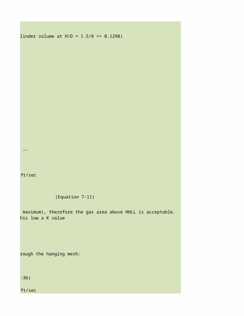
LLLL = 18 in. (per Fig. 6-24, interpolated fraction of cylinder volume at H/D = 1.5/8 => 0.1298)
Surge volume (LLLL to HHLL =(750gal/min) • (7min) = 5250 gal
Volume fraction at HHLL =
(5250gal/8750gal) + 0.1298 = 0.7298
From Fig. 6-24 @ vol. fraction = 0.7298, H/D ~ 0.685(hence, 70% was an acceptable preliminary assumption)Therefore H = HHLL = 5.48ft, Use 5.5 ft
Volume fraction at NLL (assume as 3.5 min above LLLL) = [((750gal/min) • (3.5min))/8750gal] + 0.1298 = 0.4298
From Fig. 6-24 @vol. fraction = 0.4298, H/D ~ 0.445=> NLL = 3.56 ft or 3ft 7in
13.6
V = ((28,910lb/hr)/(0.774lb/ft3) • 1/13.6ft2 • 1hr/3600sec = 0.764
Flow factor =0.763 ft/sec = 0.101 ft/sec
(44.58 - 0.774)/0.774
At these surge times de-gassing is not an issue.
Calculate Mesh Pad Area & Height --Utilizing the Sonders-Brown equation for vertical flow through the hanging mesh:
K = 0.35 ft/sec for high efficiency mist eliminator
0.867 (derating factor) -- interpolation for actual pressure (Fig. 7-36)
= 2.28
Liquid Level Calculation --
Check Gas flow factor @HHLL in Gravity Separation Section --
A = (1 - 0.7298)π (8ft/2)2 = ft2
The flow Factor is significantly below 0.5ft/sec (typical maximum), therefore the gas area above HHLL is acceptable. Additionally, liquid re-entrainment is not plausible at this low a K value
Check De-Gassing --
Vmax = (0.35 • 0.867) (44.58 - 0.774)/0.774
√( )( )/( )
√( )

4.545
This is approximately a 26 in by 26 in square mesh pad.
Inlet device can be diffuser, half open pipe, or elbow at these liquid/gas rates. Diffuser is preferred.
Nozzle Sizing
Inlet Piping = 10 in Sch. 40 (ID = 10.02 in), based on acceptable line sizing criteria, and inlet nozzle size equals pipe size.
Check Inlet Velocity Head
V =
= 21.9 ft/sec
therefore10in nozzle with diffuser is acceptableOutlet Nozzle Size = 6 in Sch. 40 (ID = 6.065in)
V =
= 51.7 ft/sec
Therefore 6 in outlet nozzle is acceptable.
The sample calculations, equations and spreadsheets presented herein were developed using examples published in the Engineering Data Book as published by the Gas Processor Suppliers Association as a service to the gas processing industry. All information and calculation formulae has been compiled and edited in cooperation with Gas Processors Association (GPA).
Amesh = [(28,910lb/hr)/(0.774lb/hr) • 1hr/3600sec]/(2.28ft/sec) =
Similar to Fig. 7-38, based on a 45° angle from the edge fo the mesh pad to the edge of the outlet nozzle, the height above the mesh pad to the nozzle should be 1/2 of the mesh pad width minus 1/2 of the nozzle diamter. Use 1 ft height above mesh pad.
Inlet Device Selection --
(268,200 + 28,910)lb/hr • 144 in2 • 1hr6.87lb/ft3 • 1 ft2 π (10.02/2)2 in2 • 3600 sec
J = (pmv2) = (6.87 • 21.92) = 3306 lb/ft•sec2 < 6000 lb/ft•sec2
28,910 lb/hr • 144 in2 • 1hr0.744 lb/ft3 • 1 ft2 π (6.065/2)2 in2 • 3600 sec
J = (0.774 • 51.72) = 2070 lb/ft•sec2 < 6000 lb/ft•sec2
√( )
( )/
( )/

While every effort has been made to present accurate and reliable technical information and calculation spreadsheets based on the GPSA Engineering Data Book sample calculations, the use of such information is voluntary and the GPA and GPSA do not guarantee the accuracy, completeness, efficacy or timeliness of such information. Reference herein to any specific commercial product, calculation method, process, or service by trade-name, trademark, and service mark manufacturer or otherwise does not constitute or imply endorsement, recommendation or favoring by the GPA and/or GPSA.The Calculation Spreadsheets are provided without warranty of any kind including warranties of accuracy or reasonableness of factual or scientific assumptions, studies or conclusions, or merchantability, fitness for a particular purpose or non-infringement of intellectual property.In no event will the GPA or GPSA and their members be liable for any damages whatsoever (including without limitation, those resulting from lost profits, lost data or business interruption) arising from the use, inability to , reference to or reliance on the information in thes Publication, whether based on warranty, contract, tort or any other legal theory and whether or not advised of the possibility of such damages.These calculation spreadsheets are provided to provide an “Operational level” of accuracy calculation based on rather broad assumptions (including but not limited to; temperatures, pressures, compositions, imperial curves, site conditions etc) and do not replace detailed and accurate Design Engineering taking into account actual process conditions, fluid properties, equipment condition or fowling and actual control set-point dead-band limitations.

(28,910 lb/hr)(268,200 lb/hr)
• Assume 10% of volume for min liquid level (LLLL) and ignore volume in heads, therefore 60% of volume is used for surge time
-- Determine the configuration and size of a separator vessel to provide surge upstream of a process unit and to separate liquids and gas. The stream is 25,000 bpd of condensate and 15 MMSCFD of gas (MW = 17.55). Process conditions are as follows:
-- select a horizontal drum with a hanging mesh for this application due to high liquid rate, 5 minute surge time, and relatively
-- Calculate a prelininary vessel size as a starting point to calculate partially filled cylinder areas/volumes. Assume required liquid surge colume controls separator sizing (as opposed to gas flowrate):
Use 70% full (typical maximum) to HHLL required total surge time of 7 minutes, with 3:1 L/D, and 18 in. LLLL
ft3

LLLL = 18 in. (per Fig. 6-24, interpolated fraction of cylinder volume at H/D = 1.5/8 => 0.1298)
ft/sec
(Equation 7-11)
Utilizing the Sonders-Brown equation for vertical flow through the hanging mesh:
(Fig. 7-36)
ft/sec
The flow Factor is significantly below 0.5ft/sec (typical maximum), therefore the gas area above HHLL is acceptable. Additionally, liquid re-

(Equation 7-11)
(Equation 7-13)
Inlet device can be diffuser, half open pipe, or elbow at these liquid/gas rates. Diffuser is preferred.
Inlet Piping = 10 in Sch. 40 (ID = 10.02 in), based on acceptable line sizing criteria, and inlet nozzle size equals pipe size.
The sample calculations, equations and spreadsheets presented herein were developed using examples published in the Engineering Data Book as published by the Gas Processor Suppliers Association as a service to the gas processing industry. All information and calculation formulae has been compiled and edited in cooperation with Gas Processors Association (GPA).
ft2
° angle from the edge fo the mesh pad to the edge of the outlet nozzle, the height above the mesh pad to the nozzle should be 1/2 of the mesh pad width minus 1/2 of the nozzle diamter. Use 1 ft height above mesh pad.
(268,200 + 28,910)lb/hr • 144 in2 • 1hr (10.02/2)2 in2 • 3600 sec
π (6.065/2)2 in2 • 3600 sec
( )/
( )/

While every effort has been made to present accurate and reliable technical information and calculation spreadsheets based on the GPSA Engineering Data Book sample calculations, the use of such information is voluntary and the GPA and GPSA do not guarantee the accuracy, completeness, efficacy or timeliness of such information. Reference herein to any specific commercial product, calculation method, process, or service by trade-name, trademark, and service mark manufacturer or otherwise does not constitute or imply endorsement, recommendation or favoring by the GPA and/or GPSA.The Calculation Spreadsheets are provided without warranty of any kind including warranties of accuracy or reasonableness of factual or scientific assumptions, studies or conclusions, or merchantability, fitness for a particular purpose or non-infringement of intellectual property.In no event will the GPA or GPSA and their members be liable for any damages whatsoever (including without limitation, those resulting from lost profits, lost data or business interruption) arising from the use, inability to , reference to or reliance on the information in thes Publication, whether based on warranty, contract, tort or any other legal theory and whether or not advised of the possibility of such damages.These calculation spreadsheets are provided to provide an “Operational level” of accuracy calculation based on rather broad assumptions (including but not limited to; temperatures, pressures, compositions, imperial curves, site conditions etc) and do not replace detailed and accurate Design Engineering taking into account actual process conditions, fluid properties, equipment condition or fowling and actual control set-point dead-band limitations.

Operating temperature = 120Operating pressure = 250 psigGas flowrate = 15 MMSCFD 28,910Liquid flowrate = 268,200 lb/hr (25,000 bpd)
= 0.774 = 0.012= 0.573 cP= 6.87 lb/ft3= 44.58 lb/ft3
LLLL to LLL = 1 min, LLL to HLL = 5 min, HLL to HHLL = 1 min
LLLL Height 18 inchessurge time 7 min
• Assume 10% of volume for min liquid level (LLLL) and ignore volume in heads, therefore 60% of volume is used for surge time60% or 0.6
Total vessel volume:
(268,200lb/hr • 1hr/60min • 1ft/44.58lb • 7 min)/ 0.6 = 1170
At 3:1 L/D:
7.9 ft
Therefore preliminary size is 8ft ID x 24 ft T/T D= 8
Application 7-3 -- Determine the configuration and size of a separator vessel to provide surge upstream of a process unit and to separate liquids and gas. The stream is 25,000 bpd of condensate and 15 MMSCFD of gas (MW = 17.55). Process conditions are as follows:
Operating Conditions --
°F,
Physical Properties --
ρg lb/ft3
μg lb/ft3
μ1
ρm
ρl
Project Surge Times for this Application --
Configuration -- select a horizontal drum with a hanging mesh for this application due to high liquid rate, 5 minute surge time, and relatively small gas flow rate.
Preliminary Vessel Size -- Calculate a prelininary vessel size as a starting point to calculate partially filled cylinder areas/volumes. Assume required liquid surge colume controls separator sizing (as opposed to gas flowrate):
• Use 70% full (typical maximum) to HHLL required total surge time of 7 minutes, with 3:1 L/D, and 18 in. LLLL
volume = 1170 ft3 = 3 • D • π • (D2/2) -> D =

LLLL = 18 in. (per Fig. 6-24, interpol. fraction of cylinder volume at H/D =
Surge volume (LLLL to HHLL =(750gal/min) • (7min) = 5250 gal
Volume fraction at HHLL =
(5250gal/8750gal) + 0.1298 = 0.7298
From Fig. 6-24 @ vol. fraction = 0.7298 H/D ~ 0.685(hence, 70% was an acceptable preliminary assumption)Therefore H = HHLL = 5.48ft, Use 5.5 ft
Volume fraction at NLL (assume as 3.5 min above LLLL) = [((750gal/min) • (3.5min))/8750gal] + 0.1298 = 0.4298
From Fig. 6-24 @vol. fraction = 0.4298, H/D ~ 0.445=> NLL = 3.56 ft or Use 3 ft 7 in
13.6
V = ((28,910lb/hr)/(0.774lb/ft3) • 1/13.6ft2 • 1hr/3600sec = 0.764
Flow factor =0.763 ft/sec = 0.102 ft/sec
(44.58 - 0.774)/0.774
At these surge times de-gassing is not an issue.
Calculate Mesh Pad Area & Height --Utilizing the Sonders-Brown equation for vertical flow through the hanging mesh:
K for high efficiency mist eliminator K = 0.35 ft/sec
(derating factor) -- interpolation for actual pressure 0.867 (Fig. 7-36)
= 2.28
Liquid Level Calculation --
Check Gas flow factor @HHLL in Gravity Separation Section --
A = (1 - 0.7298)π (8ft/2)2 = ft2
The flow Factor is significantly below 0.5ft/sec (typical maximum), therefore the gas area above HHLL is acceptable. Additionally, liquid re-entrainment is not plausible at this low a K value
Check De-Gassing --
Vmax = (0.35 • 0.867) (44.58 - 0.774)/0.774
√( )( )/( )
√( )

4.545
This is approximately a 26 in by 26 in square mesh pad.
Inlet device can be diffuser, half open pipe, or elbow at these liquid/gas rates. Diffuser is preferred.
Nozzle Sizing
Inlet Piping = 10 in Sch. 40 (ID = 10.02 in), based on acceptable line sizing criteria, and inlet nozzle size equals pipe size.
Check Inlet Velocity Head
V =
= 21.9 ft/sec
3306 lb/ft•sec2 < 6000 lb/ft•sec2
therefore10in nozzle with diffuser is acceptableOutlet Nozzle Size = 6 in Sch. 40 (ID = 6.065in)
V =
= 51.7 ft/sec
2070 lb/ft•sec2 < 6000 lb/ft•sec2
Therefore 6 in outlet nozzle is acceptable.
The sample calculations, equations and spreadsheets presented herein were developed using examples published in the Engineering Data Book as published by the Gas Processor Suppliers Association as a service to the gas processing industry. All information and calculation formulae has been compiled and edited in cooperation with Gas Processors Association (GPA).
Amesh = [(28,910lb/hr)/(0.774lb/hr) • 1hr/3600sec]/(2.28ft/sec) =
Similar to Fig. 7-38, based on a 45° angle from the edge fo the mesh pad to the edge of the outlet nozzle, the height above the mesh pad to the nozzle should be 1/2 of the mesh pad width minus 1/2 of the nozzle diamter. Use 1 ft height above mesh pad.
Inlet Device Selection --
(268,200 + 28,910)lb/hr • 144 in2 • 1hr6.87lb/ft3 • 1 ft2 π (10.02/2)2 in2 • 3600 sec
J = (pmv2) = (6.87 • 21.92) =
28,910 lb/hr • 144 in2 • 1hr0.744 lb/ft3 • 1 ft2 π (6.065/2)2 in2 • 3600 sec
J = (0.774 • 51.72) =
√( )
( )/
( )/

While every effort has been made to present accurate and reliable technical information and calculation spreadsheets based on the GPSA Engineering Data Book sample calculations, the use of such information is voluntary and the GPA and GPSA do not guarantee the accuracy, completeness, efficacy or timeliness of such information. Reference herein to any specific commercial product, calculation method, process, or service by trade-name, trademark, and service mark manufacturer or otherwise does not constitute or imply endorsement, recommendation or favoring by the GPA and/or GPSA.The Calculation Spreadsheets are provided without warranty of any kind including warranties of accuracy or reasonableness of factual or scientific assumptions, studies or conclusions, or merchantability, fitness for a particular purpose or non-infringement of intellectual property.In no event will the GPA or GPSA and their members be liable for any damages whatsoever (including without limitation, those resulting from lost profits, lost data or business interruption) arising from the use, inability to , reference to or reliance on the information in thes Publication, whether based on warranty, contract, tort or any other legal theory and whether or not advised of the possibility of such damages.These calculation spreadsheets are provided to provide an “Operational level” of accuracy calculation based on rather broad assumptions (including but not limited to; temperatures, pressures, compositions, imperial curves, site conditions etc) and do not replace detailed and accurate Design Engineering taking into account actual process conditions, fluid properties, equipment condition or fowling and actual control set-point dead-band limitations.

lb/hr(25,000 bpd)
• Assume 10% of volume for min liquid level (LLLL) and ignore volume in heads, therefore 60% of volume is used for surge time
L = 24
-- Determine the configuration and size of a separator vessel to provide surge upstream of a process unit and to separate liquids and gas. The stream is 25,000 bpd of condensate and 15 MMSCFD of gas (MW = 17.55). Process conditions are as follows:
-- select a horizontal drum with a hanging mesh for this application due to high liquid rate, 5 minute surge time, and relatively small
Preliminary Vessel Size -- Calculate a prelininary vessel size as a starting point to calculate partially filled cylinder areas/volumes. Assume required liquid surge colume controls separator sizing (as opposed to gas flowrate):
Use 70% full (typical maximum) to HHLL required total surge time of 7 minutes, with 3:1 L/D, and 18 in. LLLL
ft3

0.1298
ft/sec
(Equation 7-11)
Utilizing the Sonders-Brown equation for vertical flow through the hanging mesh:
ft/sec
The flow Factor is significantly below 0.5ft/sec (typical maximum), therefore the gas area above HHLL is acceptable. Additionally, liquid re-
(Equation 7-11)
(Equation 7-13)
Inlet device can be diffuser, half open pipe, or elbow at these liquid/gas rates. Diffuser is preferred.
Inlet Piping = 10 in Sch. 40 (ID = 10.02 in), based on acceptable line sizing criteria, and inlet nozzle size equals pipe size.
lb/ft•sec2 < 6000 lb/ft•sec2
lb/ft•sec2 < 6000 lb/ft•sec2
The sample calculations, equations and spreadsheets presented herein were developed using examples published in the Engineering Data Book as published by the Gas Processor Suppliers Association as a service to the gas processing industry. All information and calculation formulae has been compiled and edited in cooperation with Gas Processors Association (GPA).
ft2
° angle from the edge fo the mesh pad to the edge of the outlet nozzle, the height above the mesh pad to the nozzle should be 1/2 of the mesh pad width minus 1/2 of the nozzle diamter. Use 1 ft height above mesh pad.
(268,200 + 28,910)lb/hr • 144 in2 • 1hr (10.02/2)2 in2 • 3600 sec
(6.065/2)2 in2 • 3600 sec
( )/
( )/

While every effort has been made to present accurate and reliable technical information and calculation spreadsheets based on the GPSA Engineering Data Book sample calculations, the use of such information is voluntary and the GPA and GPSA do not guarantee the accuracy, completeness, efficacy or timeliness of such information. Reference herein to any specific commercial product, calculation method, process, or service by trade-name, trademark, and service mark manufacturer or otherwise does not constitute or imply endorsement, recommendation or favoring by the GPA and/or GPSA.The Calculation Spreadsheets are provided without warranty of any kind including warranties of accuracy or reasonableness of factual or scientific assumptions, studies or conclusions, or merchantability, fitness for a particular purpose or non-infringement of intellectual property.In no event will the GPA or GPSA and their members be liable for any damages whatsoever (including without limitation, those resulting from lost profits, lost data or business interruption) arising from the use, inability to , reference to or reliance on the information in thes Publication, whether based on warranty, contract, tort or any other legal theory and whether or not advised of the possibility of such damages.These calculation spreadsheets are provided to provide an “Operational level” of accuracy calculation based on rather broad assumptions (including but not limited to; temperatures, pressures, compositions, imperial curves, site conditions etc) and do not replace detailed and accurate Design Engineering taking into account actual process conditions, fluid properties, equipment condition or fowling and actual control set-point dead-band limitations.

The sample calculations, equations and spreadsheets presented herein were developed using examples published in the Engineering Data Book as published by the Gas Processor Suppliers Association as a service to the gas processing industry. All information and calculation formulae has been compiled and edited in cooperation with Gas Processors Association (GPA).

While every effort has been made to present accurate and reliable technical information and calculation spreadsheets based on the GPSA Engineering Data Book sample calculations, the use of such information is voluntary and the GPA and GPSA do not guarantee the accuracy, completeness, efficacy or timeliness of such information. Reference herein to any specific commercial product, calculation method, process, or service by trade-name, trademark, and service mark manufacturer or otherwise does not constitute or imply endorsement, recommendation or favoring by the GPA and/or GPSA.
In no event will the GPA or GPSA and their members be liable for any damages whatsoever (including without limitation, those resulting from lost profits, lost data or business interruption) arising from the use, inability to , reference to or reliance on the information in thes Publication, whether based on warranty, contract, tort or any other legal theory and whether or not advised of the possibility of such damages.These calculation spreadsheets are provided to provide an “Operational level” of accuracy calculation based on rather broad assumptions (including but not limited to; temperatures, pressures, compositions, imperial curves, site conditions etc) and do not replace detailed and accurate Design Engineering taking into account actual process conditions, fluid properties, equipment condition or fowling and actual control set-point dead-band limitations.

While every effort has been made to present accurate and reliable technical information and calculation spreadsheets based on the GPSA Engineering Data Book sample calculations, the use of such information is voluntary and the GPA and GPSA do not guarantee the accuracy, completeness, efficacy or timeliness of such information. Reference herein to any specific commercial product, calculation method, process, or service by trade-name, trademark, and service mark manufacturer or otherwise does not constitute or imply endorsement, recommendation or favoring by the GPA and/or GPSA.

While every effort has been made to present accurate and reliable technical information and calculation spreadsheets based on the GPSA Engineering Data Book sample calculations, the use of such information is voluntary and the GPA and GPSA do not guarantee the accuracy, completeness, efficacy or timeliness of such information. Reference herein to any specific commercial product, calculation method, process, or service by trade-name, trademark, and service mark manufacturer or otherwise does not constitute or imply endorsement, recommendation or favoring by the GPA and/or GPSA.

Operating pressure = 250 psig
Gas flowrate = 80000 lb/hr 103,360 ft3/hr
Light Liquid flowrate = 275000 lb/hr 26,900 bpd 6293
Heavy Liquid flowrate = 75000 lb/hr 5,181 bpd 1212Liquid droplet removal size = 150 micron
(for liq/liq separation)Liquid retention time = 10 min (normal)
(for each phase) 5 min (minimum)Liquid surge time 5 min or 12 in.
(LLL to HLL)HHLL % full 70 %
= 0.774 = 0.31 cP= 0.65 cP= 61.9= 43.7
Total vessel volume:
At 3:1 L/D:
volume = 2311
• Therefore preliminary size for settling chamber is 10 ft-ID x 30 ft-L (Actual volume of settling chamber =
@NILL, Volfrac = 0.086
Example 7-4 -- Provide a vessel to separate gas, light liquid, and heavy liquid at the conditions given below.
Design Basis --
Physical Properties --
ρg lb/ft3
μll
μhl
ρhl lb/ft3
ρll lb/ft3
Preliminary Vessel Size -- Calculate a prelininary vessel size as a starting point to calculate partially filled cylinder areas/volumes. Assume required liquid surge colume controls separator sizing (as opposed to gas flowrate):
• Utilize a standpipe option as light liquid flowrate is larger than heavy liquid flowrate
• Use 70% full to HHLL, required light and heavy phase normal retention times of 10 minutes each (bottom to NILL and NILL to NLL), and 1/2 of the light surge time between NLL and HLL, and another 1 minute between HLL and HHLL. Assume a 3:1 L/D for the settling chamber
[6,293 ft3/hr • (10 min + 3.5 min) • 1hr/60min + 1,212 ft3/hr • 10 min • 1hr/60min]/0.7
ft3 = 3 • D • π (D/2)2 =>
Calculate Levels for Preliminary Vessel Size --
[(1,212ft3/hr) • 10min • (1hr/60min)]/2,356ft3 =
From Fig. 6-24 @ vol. fraction = 0.086, H/D ~ 0.14, which corresponds to a level of 1.4 ft. As a minimum, LLILL should be set at 12 in, LILL set at 4 in above LLILL, and NILL set at 6 in above LILL, therefore set NILL at 1 ft 10 in (vol. frac of 0.125).

@NLL, Volfrac = + 0.125 = 0.57
From Fig. 6-24 @ vol. fraction = 0.57, H/D ~ 0.555
Therefore set NLL at 5 ft 7 in
@HLL, Volfrac = + 0.57 = 0.681
From Fig. 6-24 @ vol. fraction = 0.681, H/D ~ 0.644
Therefore set HLL at 6 ft 6 in
NLL to NILL (Heavy particles from light phase)(using Equation 7-5):
However, use 10in/min or 0.0139ft/s as max settling velocity
Stokes' Law settling time required =
= 3.75 ft = 270 sec =Vt 0.0139 ft/sec
Available settling time = 10min > 4.5 min, therefore heavy particles larger than 150 micron can settle from light phase between normal levels.
Vessel Bottom to NILL (Light particles from heavy phase):
Vt = 0.018 ft/sec (using Equation 7-5), use 10 in/min as max settling velocity
Stokes' Law settling time required = 2.2 min
Available settling time = 10min > 2.2 min, therefore 150 micron and larger light particles can settle from heavy phase between normal levels.
Axial Velocity (heavy phase):
From Fig. 6-24 @ vol. fraction = 0.086, H/D ~ 0.14, which corresponds to a level of 1.4 ft. As a minimum, LLILL should be set at 12 in, LILL set at 4 in above LLILL, and NILL set at 6 in above LILL, therefore set NILL at 1 ft 10 in (vol. frac of 0.125).
[(6,293ft3/hr) • 10 min • (1hr/60min)]/2,356ft3
[(6,293ft3/hr) • 2.5min • (1hr/60min)]/2,356ft3
Remaining Level Estimate (based on above calculated levels above): LILL = 1 ft 4 in, HILL = 2 ft 4 in ( 6 in above NILL), Standpipe level = 2 ft 10 in (6 in above HILL), LLL = 3 ft 10 in (12in above standpipe), HHLL = 6 ft 10 in (4 in above HLL).
Calculate Stokes' Law Terminal Velocity, Required Setting Time, and Axial Velocity --
[1488 • 32.2 ft/sec2 • (150μm • 1ft/304800μm)2 • 61.9lb/ft3 - 43.7 lb/ft3)]/ (18 • 0.31)
HTNLL to NILL /( ) /( )

=
Axial Velocity (light phase):
=
As both heavy and light phase axial velocities (horizontal at NILL and NLL are <0.05 ft/sec, axial velocity is acceptable
Light phase @ LLL and Heavy phase @ NILL:
Heavy phase retention time (bot to NILL) = 10 min, therefore light particles (150 micron) can settle from heavy phase as shown above
Light phase retention time (NILL to LLL) =
= 5.05 min
Stokes' Law settling time required =
= 2 ft = 144 sec =Vt 0.0139 ft/sec
Available settling time = 5 min > 2.4 min, therefore 150 micron heavy particles can settle from light phase between these levels
Light Phase @ NLL and Heavy Phase @ HILL:
Heavy phase retention time (bottom to HILL)=
= 20.6 min
Stokes' Law settling time required =
= 2.33 ft = 168 sec =Vt 0.0139 ft/sec
Available settling time = 20.6 min > 2.8 min, therefore 150 micron light particles can settle from heavy phase between these levels
Light phase retention time (HILL to NLL)=
8.83 min
Stokes' Law settling time required =
= 3.25 ft = 234 sec =Vt 0.0139 ft/sec
Available settling time = 8.83min > 3.9min, therefore 150 micron heavy particles can settle from light phase between these levels
Light phase @ HLL and Heavy Phase @ NILL:
Vl = (1,212ft3/hr • 1hr/3600sec)/(0.125 • π (10ft/2)2)
Vl = (6,293ft3/hr • 1hr/3600sec)/((0.57 - 0.125) • π (10ft/2)2)
Check Settling Time for Off- Normal level Operation --
((0.35 - 0.125) • 2,356 ft3)/(6,293ft3/hr • 1hr/60min)
HTLLL to NILL
(0.177 • 2,356 ft3)/(1,212ft3/hr • 1hr/60 min)
HtBOTTOM to HILL
(0.57 - 0.177 • 2,356 ft3)/(6,293ft3/hr • 1hr/60 min) =
HtHILL to NLL
/( ) /( )
/( ) /( )
/( ) /( )

Heavy phase retention time (bot to NILL) = 10 minutes, therefore light particles (150 micron) can settle from heavy phase as shown above
Light phase retention time (NILL to HLL) =
12.6 min
Stokes' Law settling time required =
= 4.67 ft = 336 sec =Vt 0.0139 ft/sec
Available settling time = 12.6 min > 5.6 min, therefore 150 micron heavy particles can settle form light phase between these levels
Inlet zone to include 2 distribution baffles, therefore use 0.5D = 5 ft
Outlet zone to account for outlet liquid nozzles, use 0.25 D = 2.5 ft
Total Length = 5ft + 2.5 ft + 30 ft = 37.5 ft
K calculated = 0.181
The size for the above vessel was calculated to be 10 ft D • 37.5 ft L which corresponds to an L/D of 3.75. Final levels are as follows:LLILL= 1 ft
LILL= 1 ft 4 inNILL= 1 ft 10 inHILL= 2 ft 4 inLLL= 3 ft 10 inNLL= 5 ft 7 inHLL= 6 ft 6 in
HHLL= 6 ft 10 in
(0.688 - 0.125 • 2,356 ft3)/(6,293ft3/hr • 1hr/60 min) =
HtNILL to HLL
Calculate Final Vessel Length --
Gravity Separation and Gas Polishing Section --
The vapor zone, and inlet/outlet nozzles should be addressed as shoun in Example 7-3. Check K through a horizontal flow mesh pad (assume mesh pad area is equal to the cross sectional area above the HHLL) using Equation 7-11:
As K calculated is less than 0.36 (derated for pressure from 0.42) for a typical wire mesh mist eliminator, the gas section is acceptable (vapor zone and inlet/outlet nozzle check not shown).
Vessel Sizing Summary --
As the settling times calculated for the above level sections for 150 micron particles were less than the available retention time, it is anticipated that smaller particles could be separated.
/( ) /( )

The sample calculations, equations and spreadsheets presented herein were developed using examples published in the Engineering Data Book as published by the Gas Processor Suppliers Association as a service to the gas processing industry. All information and calculation formulae has been compiled and edited in cooperation with Gas Processors Association (GPA).While every effort has been made to present accurate and reliable technical information and calculation spreadsheets based on the GPSA Engineering Data Book sample calculations, the use of such information is voluntary and the GPA and GPSA do not guarantee the accuracy, completeness, efficacy or timeliness of such information. Reference herein to any specific commercial product, calculation method, process, or service by trade-name, trademark, and service mark manufacturer or otherwise does not constitute or imply endorsement, recommendation or favoring by the GPA and/or GPSA.The Calculation Spreadsheets are provided without warranty of any kind including warranties of accuracy or reasonableness of factual or scientific assumptions, studies or conclusions, or merchantability, fitness for a particular purpose or non-infringement of intellectual property.In no event will the GPA or GPSA and their members be liable for any damages whatsoever (including without limitation, those resulting from lost profits, lost data or business interruption) arising from the use, inability to , reference to or reliance on the information in thes Publication, whether based on warranty, contract, tort or any other legal theory and whether or not advised of the possibility of such damages.These calculation spreadsheets are provided to provide an “Operational level” of accuracy calculation based on rather broad assumptions (including but not limited to; temperatures, pressures, compositions, imperial curves, site conditions etc) and do not replace detailed and accurate Design Engineering taking into account actual process conditions, fluid properties, equipment condition or fowling and actual control set-point dead-band limitations.
Some safety factor when applying Stokes' Law is required. Multiple iterations can be performed to achieve optimal dimensions based on vessel economics, particle separation size, and desired safety factor, however all parameters (settling times, surge times, etc) must be recalculated. This trial and error approach is typically performed via the use of a spreadsheet.

Operating pressure = 250
Gas flowrate = 80000
ft3/hr Light Liquid flowrate = 6293
ft3/hr Heavy Liquid flowrate = 1212Liquid droplet removal size = 150
(for liq/liq separation)Liquid retention time = 10
(for each phase) 5Liquid surge time 5
(LLL to HLL)HHLL % full 70%
= = ==
=
Total vessel volume:
= 2311
At 3:1 L/D:
D = 9.940 ft volume =
• Therefore preliminary size for settling chamber is 10 ft-ID x 30 ft-L (Actual volume of settling chamber = 2356 • Therefore preliminary size for settling chamber is 10 ft-ID x 30 ft-L (Actual volume of settling chamber =
@NILL, Volfrac =
-- Provide a vessel to separate gas, light liquid, and heavy liquid at the conditions given below. Application 7-4 -- Provide a vessel to separate gas, light liquid, and heavy liquid at the conditions given below.
Design Basis --
Physical Properties --
ρg
μll
μhl
ρhl
ρll
-- Calculate a prelininary vessel size as a starting point to calculate partially filled cylinder areas/volumes. Assume Preliminary Vessel Size -- Calculate a prelininary vessel size as a starting point to calculate partially filled cylinder areas/volumes. Assume required liquid surge colume controls separator sizing (as opposed to gas flowrate):
• Utilize a standpipe option as light liquid flowrate is larger than heavy liquid flowrate
Use 70% full to HHLL, required light and heavy phase normal retention times of 10 minutes each (bottom to NILL and NILL to NLL), and 1/2 of the light surge time between NLL and HLL, and another 1 minute between HLL and HHLL. Assume a 3:1 L/D for the settling chamber
• Use 70% full to HHLL, required light and heavy phase normal retention times of 10 minutes each (bottom to NILL and NILL to NLL), and 1/2 of the light surge time between NLL and HLL, and another 1 minute between HLL and HHLL. Assume a 3:1 L/D for the settling chamber
ft3 [6,293 ft3/hr • (10 min + 3.5 min) • 1hr/60min + 1,212 ft3/hr • 10 min • 1hr/60min]/0.7
ft3
Calculate Levels for Preliminary Vessel Size --
[(1,212ft3/hr) • 10min • (1hr/60min)]/2,356ft3 =
From Fig. 6-24 @ vol. fraction = 0.086, H/D ~ 0.14, which corresponds to a level of 1.4 ft. As a minimum, LLILL should be set at 12 in, LILL set at 4 in above LLILL, and NILL set at 6 in above LILL, therefore set NILL at 1 ft 10 in (vol. frac of 0.125).
From Fig. 6-24 @ vol. fraction = 0.086, H/D ~ 0.14, which corresponds to a level of 1.4 ft. As a minimum, LLILL should be set at 12 in, LILL set at 4 in above LLILL, and NILL set at 6 in above LILL, therefore set NILL at 1 ft 10 in (vol. frac of 0.125).

+ 0.125 = 0.57 @NLL, Volfrac =
From Fig. 6-24 @ vol. fraction = 0.57
Therefore set NLL at 5 ft 7 in
+ 0.57 = 0.681 @HLL, Volfrac =
From Fig. 6-24 @ vol. fraction = 0.681
Therefore set HLL at 6 ft 6 in
NLL to NILL (Heavy particles from light phase)(using Equation 7-5):
= 0.0378 ft/sec
However, use 10in/min or 0.0139ft/s as max settling velocity
Stokes' Law settling time required =
4.5 min =Vt
Available settling time = 10min > 4.5 min, therefore heavy particles larger than 150 micron can settle from light phase between normal levels. Available settling time = 10min > 4.5 min, therefore heavy particles larger than 150 micron can settle from light phase between normal levels.
Vessel Bottom to NILL (Light particles from heavy phase):
Vt = 0.018 ft/sec (using Equation 7-5), use 10 in/min as max settling velocity
Stokes' Law settling time required = 2.2 min
Available settling time = 10min > 2.2 min, therefore 150 micron and larger light particles can settle from heavy phase between normal levels. Available settling time = 10min > 2.2 min, therefore 150 micron and larger light particles can settle from heavy phase between normal levels.
Axial Velocity (heavy phase):
From Fig. 6-24 @ vol. fraction = 0.086, H/D ~ 0.14, which corresponds to a level of 1.4 ft. As a minimum, LLILL should be set at 12 in, LILL set at 4 in above LLILL, and NILL set at 6 in above LILL, therefore set NILL at 1 ft 10 in (vol. frac of 0.125).
From Fig. 6-24 @ vol. fraction = 0.086, H/D ~ 0.14, which corresponds to a level of 1.4 ft. As a minimum, LLILL should be set at 12 in, LILL set at 4 in above LLILL, and NILL set at 6 in above LILL, therefore set NILL at 1 ft 10 in (vol. frac of 0.125).
[(6,293ft3/hr) • 10 min • (1hr/60min)]/2,356ft3 +
[(6,293ft3/hr) • 2.5min • (1hr/60min)]/2,356ft3 +
Remaining Level Estimate (based on above calculated levels above): LILL = 1 ft 4 in, HILL = 2 ft 4 in ( 6 in above NILL), Standpipe level = 2 ft 10 in (6 in above HILL), LLL = 3 ft 10 in (12in above standpipe), HHLL = 6 ft 10 in (4 in above HLL).
Remaining Level Estimate (based on above calculated levels above): LILL = 1 ft 4 in, HILL = 2 ft 4 in ( 6 in above NILL), Standpipe level = 2 ft 10 in (6 in above HILL), LLL = 3 ft 10 in (12in above standpipe), HHLL = 6 ft 10 in (4 in above HLL).
Calculate Stokes' Law Terminal Velocity, Required Setting Time, and Axial Velocity --
[1488 • 32.2 ft/sec2 • (150μm • 1ft/304800μm)2 • (61.9lb/ft3 - 43.7 lb/ft3)]/ (18 • 0.31)
HTNLL to NILL /( ) /( )

0.0343 ft/sec
Axial Velocity (light phase):
0.05 ft/sec
As both heavy and light phase axial velocities (horizontal at NILL and NLL are <0.05 ft/sec, axial velocity is acceptable As both heavy and light phase axial velocities (horizontal at NILL and NLL are <0.05 ft/sec, axial velocity is acceptable
Light phase @ LLL and Heavy phase @ NILL:
Heavy phase retention time (bot to NILL) = 10 min, therefore light particles (150 micron) can settle from heavy phase as shown above Heavy phase retention time (bot to NILL) = 10 min, therefore light particles (150 micron) can settle from heavy phase as shown above
Light phase retention time (NILL to LLL) =
Stokes' Law settling time required =
2.4 min =Vt
Available settling time = 5 min > 2.4 min, therefore 150 micron heavy particles can settle from light phase between these levels Available settling time = 5 min > 2.4 min, therefore 150 micron heavy particles can settle from light phase between these levels
Light Phase @ NLL and Heavy Phase @ HILL:
Heavy phase retention time (bottom to HILL)=
Stokes' Law settling time required =
2.8 min =Vt
Available settling time = 20.6 min > 2.8 min, therefore 150 micron light particles can settle from heavy phase between these levels Available settling time = 20.6 min > 2.8 min, therefore 150 micron light particles can settle from heavy phase between these levels
Light phase retention time (HILL to NLL)=
Stokes' Law settling time required =
3.9 min =Vt
Available settling time = 8.83min > 3.9min, therefore 150 micron heavy particles can settle from light phase between these levels Available settling time = 8.83min > 3.9min, therefore 150 micron heavy particles can settle from light phase between these levels
Light phase @ HLL and Heavy Phase @ NILL:
Vl = (1,212ft3/hr • 1hr/3600sec)/(0.125 • π (10ft/2)2)
Vl = (6,293ft3/hr • 1hr/3600sec)/((0.57 - 0.125) • π (10ft/2)2)
Check Settling Time for Off- Normal level Operation --
((0.35 - 0.125) • 2,356 ft3)/(6,293ft3/hr • 1hr/60min)
HTLLL to NILL
(0.177 • 2,356 ft3)/(1,212ft3/hr • 1hr/60 min)
HtBOTTOM to HILL
(0.57 - 0.177 • 2,356 ft3)/(6,293ft3/hr • 1hr/60 min) =
HtHILL to NLL
/( ) /( )
/( ) /( )
/( ) /( )

Heavy phase retention time (bot to NILL) = 10 minutes, therefore light particles (150 micron) can settle from heavy phase as shown above Heavy phase retention time (bot to NILL) = 10 minutes, therefore light particles (150 micron) can settle from heavy phase as shown above
Light phase retention time (NILL to HLL) =
Stokes' Law settling time required =
5.6 min =Vt
Available settling time = 12.6 min > 5.6 min, therefore 150 micron heavy particles can settle form light phase between these levels Available settling time = 12.6 min > 5.6 min, therefore 150 micron heavy particles can settle form light phase between these levels
Inlet zone to include 2 distribution baffles, therefore use 0.5D =
Outlet zone to account for outlet liquid nozzles, use 0.25 D =
Total Length = 5ft + 2.5 ft + 30 ft =
K calculated = 0.181
The size for the above vessel was calculated to be 10 ft D • 37.5 ft L which corresponds to an L/D of 3.75. Final levels are as follows: The size for the above vessel was calculated to be 10 ft D • 37.5 ft L which corresponds to an L/D of 3.75. Final levels are as follows:LLILL= 1 ft
LILL= 1 ft 4 inNILL= 1 ft 10 inHILL= 2 ft 4 inLLL= 3 ft 10 inNLL= 5 ft 7 inHLL= 6 ft 6 in
HHLL= 6 ft 10 in
(0.688 - 0.125 • 2,356 ft3)/(6,293ft3/hr • 1hr/60 min) =
HtNILL to HLL
Calculate Final Vessel Length --
Gravity Separation and Gas Polishing Section --
The vapor zone, and inlet/outlet nozzles should be addressed as shoun in Example 7-3. Check K through a horizontal flow mesh pad (assume mesh The vapor zone, and inlet/outlet nozzles should be addressed as shoun in Example 7-3. Check K through a horizontal flow mesh pad (assume mesh pad area is equal to the cross sectional area above the HHLL) using Equation 7-11:
As K calculated is less than 0.36 (derated for pressure from 0.42) for a typical wire mesh mist eliminator, the gas section is acceptable (vapor zone As K calculated is less than 0.36 (derated for pressure from 0.42) for a typical wire mesh mist eliminator, the gas section is acceptable (vapor zone and inlet/outlet nozzle check not shown).
Vessel Sizing Summary --
As the settling times calculated for the above level sections for 150 micron particles were less than the available retention time, it is anticipated that As the settling times calculated for the above level sections for 150 micron particles were less than the available retention time, it is anticipated that smaller particles could be separated.
/( ) /( )

The sample calculations, equations and spreadsheets presented herein were developed using examples published in the Engineering Data Book as published by the Gas Processor Suppliers Association as a service to the gas processing industry. All information and calculation formulae has been compiled and edited in cooperation with Gas Processors Association (GPA).While every effort has been made to present accurate and reliable technical information and calculation spreadsheets based on the GPSA Engineering Data Book sample calculations, the use of such information is voluntary and the GPA and GPSA do not guarantee the accuracy, completeness, efficacy or timeliness of such information. Reference herein to any specific commercial product, calculation method, process, or service by trade-name, trademark, and service mark manufacturer or otherwise does not constitute or imply endorsement, recommendation or favoring by the GPA and/or GPSA.The Calculation Spreadsheets are provided without warranty of any kind including warranties of accuracy or reasonableness of factual or scientific assumptions, studies or conclusions, or merchantability, fitness for a particular purpose or non-infringement of intellectual property.In no event will the GPA or GPSA and their members be liable for any damages whatsoever (including without limitation, those resulting from lost profits, lost data or business interruption) arising from the use, inability to , reference to or reliance on the information in thes Publication, whether based on warranty, contract, tort or any other legal theory and whether or not advised of the possibility of such damages.These calculation spreadsheets are provided to provide an “Operational level” of accuracy calculation based on rather broad assumptions (including but not limited to; temperatures, pressures, compositions, imperial curves, site conditions etc) and do not replace detailed and accurate Design Engineering taking into account actual process conditions, fluid properties, equipment condition or fowling and actual control set-point dead-band limitations.
Some safety factor when applying Stokes' Law is required. Multiple iterations can be performed to achieve optimal dimensions based on vessel economics, particle separation size, and desired safety factor, however all parameters (settling times, surge times, etc) must be recalculated. This
Some safety factor when applying Stokes' Law is required. Multiple iterations can be performed to achieve optimal dimensions based on vessel economics, particle separation size, and desired safety factor, however all parameters (settling times, surge times, etc) must be recalculated. This trial and error approach is typically performed via the use of a spreadsheet.

psig
lb/hr 103360 ft3/hr
26900 bpd 6293 ft3/hr
5181 bpd 1212 ft3/hrmicron
min (normal)min (minimum)min or 12 in.
0.7740.31 cP0.65 cP
61.9
43.7
= 2311
2311 D = 9.94 ft
• Therefore preliminary size for settling chamber is 10 ft-ID x 30 ft-L (Actual volume of settling chamber = 2356
0.086
-- Provide a vessel to separate gas, light liquid, and heavy liquid at the conditions given below.
ft3/hr
ft3/hr
lb/ft3
lb/ft3
lb/ft3
-- Calculate a prelininary vessel size as a starting point to calculate partially filled cylinder areas/volumes. Assume required liquid surge colume controls separator sizing (as opposed to gas flowrate):
Utilize a standpipe option as light liquid flowrate is larger than heavy liquid flowrate
Use 70% full to HHLL, required light and heavy phase normal retention times of 10 minutes each (bottom to NILL and NILL to NLL), and 1/2 of the light surge time between NLL and HLL, and another 1 minute between HLL and HHLL. Assume a 3:1 L/D for the settling chamber
/hr • (10 min + 3.5 min) • 1hr/60min + 1,212 ft3/hr • 10 min • 1hr/60min]/0.7 ft3
ft3 = 3 • D • π (D/2)2 =>
ft3
Calculate Levels for Preliminary Vessel Size --
[(1,212ft3/hr) • 10min • (1hr/60min)]/2,356ft3 =
From Fig. 6-24 @ vol. fraction = 0.086, H/D ~ 0.14, which corresponds to a level of 1.4 ft. As a minimum, LLILL should be set at 12 in, LILL set at 4 in above LLILL, and NILL set at 6 in above LILL, therefore set NILL at 1 ft 10 in (vol. frac of 0.125).

0.125 = 0.5701391
@ H/D ~ 0.555
0.57 = 0.681
H/D ~ 0.644
NLL to NILL (Heavy particles from light phase)
= 0.0378 ft/sec
However, use 10in/min or 0.0139ft/s as max settling velocity
3.75 ft = 270 sec = 4.50 min0.0139 ft/sec
Available settling time = 10min > 4.5 min, therefore heavy particles larger than 150 micron can settle from light phase between normal levels.
Vessel Bottom to NILL (Light particles from heavy phase):
Vt = 0.018 ft/sec (using Equation 7-5), use 10 in/min as max settling velocity
Available settling time = 10min > 2.2 min, therefore 150 micron and larger light particles can settle from heavy phase between normal levels.
From Fig. 6-24 @ vol. fraction = 0.086, H/D ~ 0.14, which corresponds to a level of 1.4 ft. As a minimum, LLILL should be set at 12 in, LILL set at 4 in above LLILL, and NILL set at 6 in above LILL, therefore set NILL at 1 ft 10 in (vol. frac of 0.125).
[(6,293ft3/hr) • 10 min • (1hr/60min)]/2,356ft3 +
[(6,293ft3/hr) • 2.5min • (1hr/60min)]/2,356ft3 +
Remaining Level Estimate (based on above calculated levels above): LILL = 1 ft 4 in, HILL = 2 ft 4 in ( 6 in above NILL), Standpipe level = 2 ft 10 in (6 in above HILL), LLL = 3 ft 10 in (12in above standpipe), HHLL = 6 ft 10 in (4 in above HLL).
Calculate Stokes' Law Terminal Velocity, Required Setting Time, and Axial Velocity --
m • 1ft/304800μm)2 • (61.9lb/ft3 - 43.7 lb/ft3)]/ (18 • 0.31)
/( )

= 0.0343 ft/sec
0.05 ft/sec
As both heavy and light phase axial velocities (horizontal at NILL and NLL are <0.05 ft/sec, axial velocity is acceptable
Light phase @ LLL and Heavy phase @ NILL:
Heavy phase retention time (bot to NILL) = 10 min, therefore light particles (150 micron) can settle from heavy phase as shown above
= 5.05 min
2 ft = 144 sec = 2.40 min0.0139 ft/sec
Available settling time = 5 min > 2.4 min, therefore 150 micron heavy particles can settle from light phase between these levels
Light Phase @ NLL and Heavy Phase @ HILL:
Heavy phase retention time (bottom to HILL)=
= 20.6 min
2.33 ft = 168 sec = 2.8 min0.0139 ft/sec
Available settling time = 20.6 min > 2.8 min, therefore 150 micron light particles can settle from heavy phase between these levels
8.83 min
3.25 ft = 234 sec = 3.9 min0.0139 ft/sec
Available settling time = 8.83min > 3.9min, therefore 150 micron heavy particles can settle from light phase between these levels
Light phase @ HLL and Heavy Phase @ NILL:
(1,212ft3/hr • 1hr/3600sec)/(0.125 • π (10ft/2)2)
(6,293ft3/hr • 1hr/3600sec)/((0.57 - 0.125) • π (10ft/2)2)
Check Settling Time for Off- Normal level Operation --
3/hr • 1hr/60min)
/hr • 1hr/60 min) =
/( )
/( )
/( )

Heavy phase retention time (bot to NILL) = 10 minutes, therefore light particles (150 micron) can settle from heavy phase as shown above
12.6 min
4.67 ft = 336 sec = 5.6 min0.0139 ft/sec
Available settling time = 12.6 min > 5.6 min, therefore 150 micron heavy particles can settle form light phase between these levels
Inlet zone to include 2 distribution baffles, therefore use 0.5D = 5.0 ft
Outlet zone to account for outlet liquid nozzles, use 0.25 D = 2.5 ft
37.5 ft
The size for the above vessel was calculated to be 10 ft D • 37.5 ft L which corresponds to an L/D of 3.75. Final levels are as follows:
3/hr • 1hr/60 min) =
Gravity Separation and Gas Polishing Section --
The vapor zone, and inlet/outlet nozzles should be addressed as shoun in Example 7-3. Check K through a horizontal flow mesh pad (assume mesh pad area is equal to the cross sectional area above the HHLL) using Equation 7-11:
As K calculated is less than 0.36 (derated for pressure from 0.42) for a typical wire mesh mist eliminator, the gas section is acceptable (vapor zone and inlet/outlet nozzle check not shown).
As the settling times calculated for the above level sections for 150 micron particles were less than the available retention time, it is anticipated that smaller particles could be separated.
/( )

The sample calculations, equations and spreadsheets presented herein were developed using examples published in the Engineering Data Book as published by the Gas Processor Suppliers Association as a service to the gas processing industry. All information and calculation formulae has been compiled and edited in cooperation with Gas Processors Association (GPA).While every effort has been made to present accurate and reliable technical information and calculation spreadsheets based on the GPSA Engineering Data Book sample calculations, the use of such information is voluntary and the GPA and GPSA do not guarantee the accuracy, completeness, efficacy or timeliness of such information. Reference herein to any specific commercial product, calculation method, process, or service by trade-name, trademark, and service mark manufacturer or otherwise does not constitute or imply endorsement, recommendation or favoring by the GPA and/or GPSA.The Calculation Spreadsheets are provided without warranty of any kind including warranties of accuracy or reasonableness of factual or scientific assumptions, studies or conclusions, or merchantability, fitness for a particular purpose or non-infringement of intellectual property.In no event will the GPA or GPSA and their members be liable for any damages whatsoever (including without limitation, those resulting from lost profits, lost data or business interruption) arising from the use, inability to , reference to or reliance on the information in thes Publication, whether based on warranty, contract, tort or any other legal theory and whether or not advised of the possibility of such damages.These calculation spreadsheets are provided to provide an “Operational level” of accuracy calculation based on rather broad assumptions (including but not limited to; temperatures, pressures, compositions, imperial curves, site conditions etc) and do not replace detailed and accurate Design Engineering taking into account actual process conditions, fluid properties, equipment condition or fowling and actual control set-point dead-band limitations.
Some safety factor when applying Stokes' Law is required. Multiple iterations can be performed to achieve optimal dimensions based on vessel economics, particle separation size, and desired safety factor, however all parameters (settling times, surge times, etc) must be recalculated. This trial and error approach is typically performed via the use of a spreadsheet.

The sample calculations, equations and spreadsheets presented herein were developed using examples published in the Engineering Data Book as published by the Gas Processor Suppliers Association as a service to the gas processing industry. All information and calculation formulae has been compiled and edited in cooperation with Gas Processors Association (GPA).While every effort has been made to present accurate and reliable technical information and calculation spreadsheets based on the GPSA Engineering Data Book sample calculations, the use of such information is voluntary and the GPA and GPSA do not guarantee the accuracy, completeness, efficacy or timeliness of such information. Reference herein to any specific commercial product, calculation method, process, or service by trade-name, trademark, and service mark manufacturer or otherwise does not constitute or imply endorsement, recommendation or favoring by the GPA and/or GPSA.
In no event will the GPA or GPSA and their members be liable for any damages whatsoever (including without limitation, those resulting from lost profits, lost data or business interruption) arising from the use, inability to , reference to or reliance on the information in thes Publication, whether based on warranty, contract, tort or any other legal theory and whether or not advised of the possibility of such damages.These calculation spreadsheets are provided to provide an “Operational level” of accuracy calculation based on rather broad assumptions (including but not limited to; temperatures, pressures, compositions, imperial curves, site conditions etc) and do not replace detailed and accurate Design Engineering taking into account actual process conditions, fluid properties, equipment condition or fowling and actual control set-point dead-band limitations.

While every effort has been made to present accurate and reliable technical information and calculation spreadsheets based on the GPSA Engineering Data Book sample calculations, the use of such information is voluntary and the GPA and GPSA do not guarantee the accuracy, completeness, efficacy or timeliness of such information. Reference herein to any specific commercial product, calculation method, process, or service by trade-name, trademark, and service mark manufacturer or otherwise does not constitute or imply endorsement, recommendation or favoring by the GPA and/or GPSA.
These calculation spreadsheets are provided to provide an “Operational level” of accuracy calculation based on rather broad assumptions (including but not limited to; temperatures, pressures, compositions, imperial curves, site conditions etc) and do not replace detailed and accurate Design Engineering taking into account actual process conditions, fluid properties, equipment condition or fowling and actual control set-point dead-band limitations.

While every effort has been made to present accurate and reliable technical information and calculation spreadsheets based on the GPSA Engineering Data Book sample calculations, the use of such information is voluntary and the GPA and GPSA do not guarantee the accuracy, completeness, efficacy or timeliness of such information. Reference herein to any specific commercial product, calculation method, process, or service by trade-name, trademark, and service mark manufacturer or otherwise does not constitute or imply endorsement, recommendation or favoring by the GPA and/or GPSA.


![[MS-XLSX]: Excel (.xlsx) Extensions to the Office Open XML ...MS-XLSX]-190319.pdfExcel (.xlsx) Extensions to the Office Open XML SpreadsheetML File Format Intellectual Property Rights](https://static.fdocuments.us/doc/165x107/5ff28f9fff20d6343762b03e/ms-xlsx-excel-xlsx-extensions-to-the-office-open-xml-ms-xlsx-190319pdf.jpg)


![[MS-XLSX]: Excel (.xlsx) Extensions to the Office Open XML ...interoperability.blob.core.windows.net/files/MS-XLSX/[MS-XLSX].pdf · [MS-XLSX]: Excel (.xlsx) Extensions to the Office](https://static.fdocuments.us/doc/165x107/5e14a2c69b6a8672683323c2/ms-xlsx-excel-xlsx-extensions-to-the-office-open-xml-ms-xlsxpdf-ms-xlsx.jpg)