Section 1.0 Operation and Maintenance Manual Prepared For ...
58
JB2778-17 INDO-MIM 1 AMKT24D24 RAMCO EQUIPMENT CORPORATION 9/18/2017 Section 1.0 Operation and Maintenance Manual Prepared For: INDO-MIM Model # AMKT24D24EWRRDR Serial # JB2778-17 (SYSTEM REPRESENTATION)
Transcript of Section 1.0 Operation and Maintenance Manual Prepared For ...

JB2778-17 INDO-MIM 1
AMKT24D24 RAMCO EQUIPMENT CORPORATION 9/18/2017
Section 1.0 Operation and Maintenance Manual
Prepared For: INDO-MIM Model # AMKT24D24EWRRDR
Serial # JB2778-17
(SYSTEM REPRESENTATION)

JB2778-17 INDO-MIM 2
AMKT24D24 RAMCO EQUIPMENT CORPORATION 9/18/2017
Section 2.0 Table of Contents
Section 1.0 .......................................................................................................................1 Operation and Maintenance Manual
Section 2.0 .......................................................................................................................2 Table of Contents
Section 3.0 .......................................................................................................................4 Safety Devices and Precautions
Section 4.0 .......................................................................................................................5 Introduction
Section 4.1 .......................................................................................................................8 Reference Table
Section 5.0 .......................................................................................................................9 Installation
Section 6.0 .......................................................................................................................10 Start Up and Operation
Section 6.1 .......................................................................................................................16 Digital Indicating Temperature
Section 6.2 .......................................................................................................................19 Digital Cycle Timer
Section 6.3 .......................................................................................................................20 Filtration/Turbulation System
Section 6.4 .......................................................................................................................21 Dryer
Section 6.5 .......................................................................................................................23 Oil Removal System OR6-CVS
Section 7.0 .......................................................................................................................29 General Assembly
Section 8.0 .......................................................................................................................30 RS Logix Programming
Section 8.1 .......................................................................................................................31 Electrical Wiring Diagram(s)
Section 9.0 .......................................................................................................................36 Pneumatic Diagrams
Section 10.0 .....................................................................................................................39 Maintenance
Section 10.1 .....................................................................................................................40 Daily Inspection and Operations Check
Section 10.2 .....................................................................................................................41 Daily Start-Up Routine

JB2778-17 INDO-MIM 3
AMKT24D24 RAMCO EQUIPMENT CORPORATION 9/18/2017
Section 10.3 .....................................................................................................................42 Preventative Maintenance Schedule (Weekly)
Section 10.4 .....................................................................................................................43 Cleaning the Tanks
Section 10.5 .....................................................................................................................44 Chanel Guide Lubrication
Section 10.6 .....................................................................................................................45 Platform Adjustmants
Section 10.7 .....................................................................................................................46 Repair – Fuses, Valves, Cylinders
Section 11.0 .....................................................................................................................49 Trouble Shooting Electrical, Pneumatic
Section 12.0 .....................................................................................................................52 Electrical / Pneumatics Parts List
Section 13.0 .....................................................................................................................56 Warranty Policy and Return Procedure

JB2778-17 INDO-MIM 4
AMKT24D24 RAMCO EQUIPMENT CORPORATION 9/18/2017
Section 3.0 MK Safety Devices and
Precautions All personnel using the equipment should read this manual thoroughly and understand its contents as well as familiarize themselves with precautionary instructions pertaining to the usage and handling of chemicals used in the tank. If necessary, contact the chemical manufacturer for specific information. 1. Ensure safety precautions are followed for the chemical(s) to be used. 2. Consult with the chemical manufacturer and MSDS sheets provided. 3. Do not use flammable liquids in this system. 4. Do not allow the cleaning solution to come in contact with the body. Wear gloves and
eye protection. 5. Keep hands out of the cleaning tank. 6. Use only cleaning solutions that are compatible with the parts to be cleaned and the
materials of construction of the tank. See Ramco Warranty. 7. Periodically analyze the solution to determine the level of contamination. 8. Do not operate the cleaner in an ungrounded mode. Do not use "cheater plugs," or cut
off the ground terminal of the electrical cord plug. 9. Verify the proper line voltage requirements by checking the serial nameplate located on
the inside of the control panel door.

JB2778-17 INDO-MIM 5
AMKT24D24 RAMCO EQUIPMENT CORPORATION 9/18/2017
Section 4.0 Introduction
FUNCTION The system AMKT24D24WRRDR automatically washes, rinses and dries various parts loaded into baskets and placed onto a loading station. The system transfers the baskets through the entire process without manual assistance and shuts off when complete. The system consists of the following: 1. (1) Washing Station 2. (2) Rinsing Stations 3. (1) Dry Station 4. (1) Oil Dip Station 4. Transfer Mechanism - Automation 5. Control Panel The first, second and third stations consist of a wash and DI rinse and Rinse stages. The fourth and fifth stations are a dryer stage and an oil dip. The operator loads directly onto the load conveyor at the start of the line (Reference System Operation). An unload conveyor on the exit side of the line is provided. Process flow is from left to right. OPERATING DESCRIPTION The system can process up to five baskets at a time. The transfer mechanism consists of a pneumatic drive with air over oil control connected to a walking beam. The walking beam moves left and right on bearings over hardened steel shafts and articulates ninety degrees at the beginning and end of each cycle. The walking beam has five shifting arms. Transfer is very accurate and smooth. WASHING, RINSING AND DRYING STATIONS All functions are incorporated into a standard electrically heated single Stage System. The system is constructed of stainless steel with stainless steel covers and stainless steel roller conveyor platforms. Each station has its own heating system with temperature controller. Dual stroke oscillation is standard. It provides a short stroke for general cleaning or a long stroke (in and out of solution). The individual agitation modes (platform oscillation and solution turbulence) are used together to provide Dynamic Flow Combinations™ for fast effective cleaning using mild biodegradable detergents.
SYSTEM: AMKT24D24EWRRDR (Left to Right Flow)

JB2778-17 INDO-MIM 6
AMKT24D24 RAMCO EQUIPMENT CORPORATION 9/18/2017
RAMCO Model MKT24EWRR
➢ Stainless steel construction ➢ Flange-up perimeter solution drip lip ➢ 150 pound load capacity ➢ Patented NFPA Floating Cylinders ➢ Dual stroke platform oscillation
Stage 1 - Sonic Wash Electrically heated, 6000 watts, 460/3/60 2 RAMCO Floating cylinder Split platform roller conveyor Digital indicating temperature controller Solution low level safety Ultrasonic Package Ultrasonics, 2000 watts, sweep frequency, hard chrome Dual cascading timers Multiple Rollover Turbo/Filter system, ¾ HP, 4x6 filter housing OR6-CVS oil removal system with water makeup
Stage 2 - Overflowing Rinse Electrically heated, 6000 watts, 460/3/60 2 RAMCO Floating cylinder Platform roller conveyor Digital indicating temperature controller Solution low level safety Digital cycle timer – using sonic stage Overflow weir with mixing piping Turbo/Filter system, ¾ HP, 4x6 filter housing Stage 3 - Cascading Rinse Electrically heated, 6000 watts, 460/3/60 2 RAMCO Floating cylinder Platform roller conveyor Digital indicating temperature controller Solution low level safety Digital cycle timer – using sonic stage Overflow weir with mixing piping Turbo system, ¾ HP Power cover Nema 12 panel with disconnect sized disconnect for load

JB2778-17 INDO-MIM 7
AMKT24D24 RAMCO EQUIPMENT CORPORATION 9/18/2017
RAMCO Model MKD24EDR ➢ Stainless steel construction ➢ Flange-up perimeter solution drip lip ➢ 150 pound load capacity ➢ Patented NFPA Floating Cylinders ➢ Dual stroke platform oscillation
Stage 4 - Hot Air Knife Dryer Electrically heated, 18000 watts 2 RAMCO Floating cylinder Digital indicating temperature controller High temperature roller platform conveyor Digital cycle timer Power cover Nema 12 panel with disconnect 60 AMP Insulated center wall
Stage 5 - Unheated water displacement tank 2” RAMCO Floating cylinder Platform roller conveyor Sloped bottom tank Sight glass Gooseneck overflow for water Digital cycle timer
Automation - AMKD24EWRRD Load conveyor with proximity sensor Unload conveyor by ACT auto stop limit switch and interrupt sent loose Automation Ready Painted steel automation guard NO Fabricated base Ram Tough Automation System
o Six arm walking beam with air-over-oil pneumatic drive o Thomson linear bearings o Allen Bradley MicroLogix 1400 o Pedestal mounted remote Operators Control Station o Manual and automatic mode selection
Selector switch to by-pass stage 4 or stage 5 (cover lockout)

JB2778-17 INDO-MIM 8
AMKT24D24 RAMCO EQUIPMENT CORPORATION 9/18/2017
Section 4.1 Reference Table
General Assembly Section 7.0 Control Circuit (RS Logix V.7.) Section 8.0 Electrical Diagram(s) Section 8.1 Pneumatic Diagram(s) Section 9.0

JB2778-17 INDO-MIM 9
AMKT24D24 RAMCO EQUIPMENT CORPORATION 9/18/2017
Section 5.0 Installation
Please read all of the instructions before starting the installation. If you have any further questions contact the RAMCO Hotline at 800-553-3650. 1. Carefully remove packaging from the machine. Ensure no damage to insulation panels,
controls or connections. 2. Locate the machine in the designated location. Add shims under the base and level in
both directions. Allow access space completely around the unit. Make certain the selected location will provide access to the required electrical, air and drainage facilities.
3. Refer to the electrical diagram for amperage requirements. Bring the proper wiring to
the electrical control panels.
4. Refer to the pneumatic diagram. Bring the proper size line to the pneumatic controls. See pneumatic adjustments (Section 11.0).
5. Bring the proper water fill line to the machine. Reference Section 7.0 – General
Assembly 6. Bring the proper drain line to the machine. Reference Section 7.0 – General Assembly 7. Bring the proper overflow line to the machine. Reference Section 7.0 – General
Assembly
Section 6.0

JB2778-17 INDO-MIM 10
AMKT24D24 RAMCO EQUIPMENT CORPORATION 9/18/2017
Start Up and Operation
SERIAL NUMBER JB2778-17 MODEL AMKT24D24WRRDR
Locate the main unit (the skid base with the console) with space at the rear to provide access for service. Pneumatics There is a single Air Drop: It is the 3/8” NPT main service connection as shown on the General Assembly. Supply the inlet with 16-20 SCFM @ 80-120 PSI. Before connecting air to the system, make certain that the transfer arms are in the up position. If not, gently manually rotate them up to the vertical position. Electrical The system has two electrical drops. Reference the General Assembly in Section 7.0. Connections are brought into each of the disconnect switches on the control panels. The machines are wired for 460V/3/60. Water A 3/4” water fill connection and a 1” drain valve is provided for each wet stage. The Stage One Wash has a 1-1/2” NPT overflow sweep dam connected to an oil removal system.
DESCRIPTION OF THE OPERATORS CONTROL

JB2778-17 INDO-MIM 11
AMKT24D24 RAMCO EQUIPMENT CORPORATION 9/18/2017
RUN SECTION Panel Power White Push Button PB-1 Turns the automation system on and off. Note that the main disconnect switches must be engaged at each of the panels and the panel power switches turned on at each panel. Mode Selector Switch SW-27 Auto - is used for automatic operation of the system. Man - is used for system debug. Cycle Start Green Push Button PB-8 Starts the automation process. Note that the baskets must be properly indexed between the proximity sensors on the load conveyor to allow the system to energize. Cycle Stop Push Button PB-7 Terminates the automation cycle and opens the covers, if closed. Cycle Interrupt Black Button PB-5 (also located on unload conveyor) Stops the transfer arms from moving when the button is pushed in. The arms will re-energize when the button is pulled out.

JB2778-17 INDO-MIM 12
AMKT24D24 RAMCO EQUIPMENT CORPORATION 9/18/2017
Emergency Stop Push Button PB-20 Shuts the automation system down. Requires the use of the Mode, Transfer and Arm Selector Switches to reset the system. See Transfer Debug below. Cover Lock Out Selector Switch SW-22 Keeps the cover open throughout the processing cycle. Used for cleaning parts that would otherwise hit the cover during agitation. DEBUG SECTION Transfer Debug SW-24 Used for Debug. Select Debug position to clear a jam (see below) and return to Run position to Home walking arm assembly prior to restarting the process. Arms Selector Switch SW-25 This is a spring loaded switch. It is used for system debug with the Mode Selector Switch in the hand position. Up - raises the arms. Down - lowers the arms. Transfer Selector Switch SW-26 This spring loaded switch is used for system debug with the Mode Selector Switch in the manual position. Forward - sends the transfer unit forward. Reverse - sends the transfer system backward. DEBUG PROCEDURE If the transfer system jams during the cycle press in the E-stop. To clear the jam, pull out the E-stop. Place the Mode Selector Switch SW-27 in the Manual position. Switch SW-24 into Debug. Push in the White Power Panel Button. Then using the Transfer Selector Switch SW-26 back up or advance the walking assembly as required to clear the jam. Remove the basket. When cleared make sure that the arms are in the up position using the Arms Selector Switch and then turn the Mode Selector Switch to the Auto mode. Then places the transfer switch SW-24 into run mode. The transfer system will automatically go to the home position. Reload the basket at the beginning of the line. Press the Start Push Button to restart the automatic process. Amber Pilot Light PL-23 When lit up, the platform is not up. The light must be not be lit for the machine to transfer.

JB2778-17 INDO-MIM 13
AMKT24D24 RAMCO EQUIPMENT CORPORATION 9/18/2017
OPERATING PROCEDURE - AUTOMATIC MODE
The system automatically processes each basket placed onto the Loading Station platform by the operator or inbound conveyor. If an operator loads the basket, they must press the green start button. If an inbound conveyor loads the basket, it must sequence the circuit to start the cycle. In either scenario, it is critical that the basket is loaded precisely on the Loading Station platform in the loading zone to interface between the transfer arms and in proximity to the sensor. Note – The RED LED indicator lights on the (2) basket loading proximity switches will indicate when the basket is properly located.
1. Before connecting air to the system ensure that the transfer arms are in the up
position. If not, gently manually rotate them up to the vertical position. 2. Connect a 3/8” airline to the air inlet valve located on the operators panel support
frame. 3. Open the 3/8” air shut off valve. 4. Ensure that all elevator “up/down” toggles are in the up position. 5. Turn each disconnect switch on. 6. Turn each console panel power switch on. 7. Push the operators control panel power switch PB-1 on. 8. Select Cover Lockout SW-22 on or off using the selector switch on the operators control
panel. 9. Press the Cycle Stop Push Button PB-7 push button located on the operators control
panel. The covers will now open and the elevators will rise to the up positions. NOTE: All upper toggle valves must be in the “up” position in order for the platforms to
raise to the up position. 10. Put the Mode Selector Switch SW-27 in the Auto position. Note: The transfer system
will move to the home position. 11. Load a basket onto the loading zone. A red LED indictor will light when the basket is in
position.

JB2778-17 INDO-MIM 14
AMKT24D24 RAMCO EQUIPMENT CORPORATION 9/18/2017
IMPORTANT: The basket must engage both proximity sensors when it is loaded on the load conveyor. If the basket is not properly loaded, the machine will go into interrupt mode!
12. Press the Cycle Start Green Push Button PB-8. The automatic transfer mechanism will
now energize and transfer the first basket onto the first stage. 13. All five elevators will descend into their respective processing chambers and the covers
close automatically unless the bypass switch (located on the PLC stand) is placed on stage 4 or stage 5. Each process cycle will now begin.
14 When the timed cycles are complete the system will signal the covers to open, the
elevators to rise to their up positions and the automation system to transfer all baskets to the next stage.
15. The system will process the basket(s) throughout the entire system. If the system is not
reloaded, the program will continue through to completion of all stages and shut off. 16. To restart the system simply reload and press the start button (Ref. above). 17. A limit switch is located on the unload conveyor. It is designed to stop the system
(interrupt transfer) if a basket has not been cleared from the zone. PL-22 cycle interrupt pilot light will be flashing until the basket is cleared. In addition, the transfer will continue its transfer after the basket is cleared.
OPERATING PROCEDURE - MANUAL MODE Note: Allow the machine to complete cycle. This means the last basket must be processed onto the unload conveyor. 1. Turn mode selector switch SW-27 to manual. (Note: Check that Automation Arms are
in the “up” position. 2. Load basket onto wash, rinse or dry stage. Press cycle start PB-8. Platforms will lower
and covers will close for time set on longest timer. When timer(s) time out covers will open and platforms will raise.
Note: To terminate cycle before timers time out, press push button PB-7 to open cover(s) and raise platform(s)

JB2778-17 INDO-MIM 15
AMKT24D24 RAMCO EQUIPMENT CORPORATION 9/18/2017
HOLDING MODE Used for temporary shutdown during breaks or lunchtime. Note: Allow machine to complete cycle. This means the last basket must be processed onto the unload conveyor. 1. Turn vented ball valve on backside of PLC panel off. This will cause platforms to lower
and covers to close. RETURN TO OPERATING MODE FROM THE HOLDING MODE 1. Turn vented ball valve to the on position. Covers will open and platforms will raise. 2. Load basket. Be sure it is positioned properly (prox. sensor on load conveyor should
light). 3. Press cycle start push button PB-1 on PLC panel. THIS MACHINE IS EQUIPPED WITH A SLEEP MODE:
1. After the last basket is processed onto the unload conveyor, a “thirty” minute timer starts.
2. If a new basket has not been loaded, the platforms lower and the covers close to conserve heat.
3. To restart the system, press the Green Start Button P/B 8 on the PLC Panel. The covers
will open and the platforms will rise to the up position.
4. Load a basket. Ensure the (2) proxes on the load conveyor are lit, and again press the Green Start Button P/B 8.

JB2778-17 INDO-MIM 16
AMKT24D24 RAMCO EQUIPMENT CORPORATION 9/18/2017
Section 6.1 Digital Temperature Controller
DIGITAL TEMPERATURE CONTROLLER
1/16th DIN Autotune PID temperature controller -
9900
Key features of the 9900 are:
• Autotune PID for easy set-up
• Dual-output: 5A relay plus SSR drive or
• Dual-output: 5A relay plus 2A relay
• IP54 sealed fascia
• 4 bright LEDs to 1° or 0.1° in °C or °
• Positive feel buttons
• Comprehensive alarm modes
• 9 thermocouples, RTD/PT100 inputs
• 115VAC or 230VAC options

JB2778-17 INDO-MIM 17
AMKT24D24 RAMCO EQUIPMENT CORPORATION 9/18/2017

JB2778-17 INDO-MIM 18
AMKT24D24 RAMCO EQUIPMENT CORPORATION 9/18/2017
Instructions to change the CAL9900 Fahrenheit temperature to Centigrade
1. With the power on, remove the front cover plate; gray with green buttons. 2. Switch the jumper to the (2) right pins. This will put you in the programming mode.
“0.0” should be showing on the display. The digit on the right is the function code. The digit on the left is the option code.
3. Press the rightmost button to function 22. The display should read “1.22” with the “22”
blinking. 4. Press the leftmost button to get to the option codes. The display should read still
“1.22” but now with the “1” blinking. 5. Press the rightmost button until the display reads “0.22”. This is the centigrade option. 6. Press the button second from the left. This exits the programming mode. 7. The actual temperature will be displayed in centigrade. 8. Switch the jumper to the (2) left pins. 9. Replace the front cover plate.

JB2778-17 INDO-MIM 19
AMKT24D24 RAMCO EQUIPMENT CORPORATION 9/18/2017
Section 6.2 Digital Cycle Timer
EAGLE SIGNAL “LED” TIMER SETUP & PROGRAMMING
MODEL B506-2001 (1/23/13)
TO PROGRAM TIMER FUNCTIONS: (FACTORY SET) PROGRAM FUNCTIONS AS LISTED BELOW PRESS AND HOLD THE “P” BUTTON FOR 3 SECONDS. TO SCROLL TO THE NEXT FUNCTION HIT THE “P” BUTTON AGAIN. WHEN DONE PROGRAMMING HOLD THE “P” BUTTON FOR 3 SECONDS. Func int2 Out 2 p2 P20 se Trn1: m/s Trn2 s Dec2 ---- Tdir dn Prst on Frst off Slul o TO SET OUTPUT 1 TIME AND OUTPUT 2 TIME SETTING OUTPUT 1 TIME: (OUTPUT 1 SETS THE CYCLE TIME) PRESS THE “P” BUTTON AND PUT IN THE DESIRED TIME. NEXT, IF YOU PRESS THE “P” BUTTON A SECOND TIME, THIS PROGRAMS OUTPUT 2. (OUTPUT 2 PULSES THE POWER COVER TO OPEN. THIS IS FACTORY SET FOR 1 SECOND. DO NOT EXCEED 1 SECOND FOR OUTPUT 2) PRESS THE STOP PUSH BUTTON TO RESET THE TIMER OR HOLD IN BOTH THE “E” & “P” BUTTON TOGETHER FOR 1 SECOND. TIMER IS NOW READY FOR OPERATION. EXAMPLE OF TIME SETTING: THERE ARE FOUR BUTTONS 1,2,3 & 4 BELOW THE DIGITS THAT ARE USED TO SET THE DESIRED TIME. PRESS EACH OF THE DIGITS UNTIL THE DESIRED TIME IS SET. THEN PRESS THE STOP BUTTON TO RESET THE TIMER

JB2778-17 INDO-MIM 20
AMKT24D24 RAMCO EQUIPMENT CORPORATION 9/18/2017
Section 6.3 Turbo Systems
Ramco turbulating systems use high volume pumps and closed looped manifolds with multiple solution injectors directed at the working zone. They provide an even flow of turbulence over, under, around and through components. The system accelerates the cleaning time and improves overall effectiveness in washing and/or rinsing. To remove solids from the cleaning solution a bag filter is incorporated on the suction side of the system. This process is intended to reduce the frequency of cleanout of the Migi-Kleen thus providing more production time and less down time. 1. Check to see that the valve in the pump suction line is wide open. Ensure that there is
adequate cleaning solution in the tank (a minimum of 2/3 full). 2. Adjust the (metering) ball valve in the pump discharge line to half open. 3. Check the rotation of the pump (three phase system only) as follows: Turn the Turbo on/off switch on (hand position for systems with three position selector switches) and then off as quickly as possible. Have another person observe the rotation of the pump. It should be turning in the direction of the arrow on the pump. If its turning in the opposite direction have a trained electrician switch any two wires on the pump starter. 4. Turn the Turbo switch on (auto position on three position selector switches). 5. Adjust the metering valve so that the flow discharging into the tank is maximum
without causing foaming. NOTE: This turbo/filtration system is safety interlocked to cycle on and off when the cover
closes and opens respectively. A proximity sensor is located at the rear of the cover just below the cover spring. To adjust the discharge flow, open the cover and place the head of a screwdriver over the sensor. With the switch in the on position the system will energize. IMPORTANT -- DO NOT ADJUST THE SYSTEM WITH LOW LIQUID LEVEL (see Section 5.0) AS SPLASHING COULD RESULT. CAUTION WEAR PROTECTIVE GOGGLES AND CLOTHING.
6. If excessive foaming occurs check with the chemical manufacturer. An additive to the
chemical can be prescribed to control or eliminate the problem.
JB2778-17 INDO-MIM 21
AMKT24D24 RAMCO EQUIPMENT CORPORATION 9/18/2017
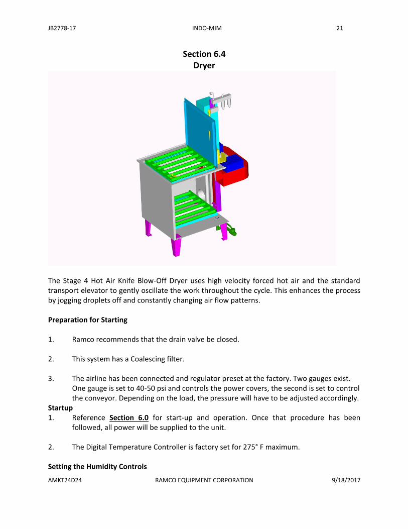
Section 6.4 Dryer
The Stage 4 Hot Air Knife Blow-Off Dryer uses high velocity forced hot air and the standard transport elevator to gently oscillate the work throughout the cycle. This enhances the process by jogging droplets off and constantly changing air flow patterns. Preparation for Starting 1. Ramco recommends that the drain valve be closed. 2. This system has a Coalescing filter. 3. The airline has been connected and regulator preset at the factory. Two gauges exist.
One gauge is set to 40-50 psi and controls the power covers, the second is set to control the conveyor. Depending on the load, the pressure will have to be adjusted accordingly.
Startup 1. Reference Section 6.0 for start-up and operation. Once that procedure has been
followed, all power will be supplied to the unit. 2. The Digital Temperature Controller is factory set for 275° F maximum. Setting the Humidity Controls

JB2778-17 INDO-MIM 22
AMKT24D24 RAMCO EQUIPMENT CORPORATION 9/18/2017
1. Air Makeup Damper. This is a half-moon shaped damper located on the air return duct at the rear of the machine. Its primary function is to allow fresh air into the dryer to control humidity. When fully opened, the maximum amount of fresh air is brought into the drying chamber.
2. Air Discharge Shutter. This device is located directly behind the cover hinge. It is used in
conjunction with the air make-up damper to allow humid air to exit the drying chamber. It is generally set in proportion to the air make up damper.
Hot Air Knife The Hot Air Knife is located along the inside front wall of the drying chamber. The slot
is adjustable from 1/4" to 3”. It is factory set at 3/4”. If adjustment is required follow the steps below:
Adjusting the Hot Air Knife: 1. Loosen (3) 1/4" bolts on each Air Knife and adjust to desired opening. 2. Tighten the bolts to secure in place.
a. Smaller openings produce higher velocity but lower volumes. b. Wider openings produce higher volumes but lower velocity.
C. As a guideline use volume over velocity. Adjusting the Main Air Knife Mounting Plate: The purpose of the mounting plate is to raise or lower the hot air knife. Loosen the (4)
1/4" bolts and move up or down to the desired height. It can be moved approximately 3-1/2" up or down. It should also be noted that the rectangular opening is not in the center of the mounting plate. As such the plate can be rotated 180 degrees to get the air knife into a lower position. It is factory set with the opening in the higher position.
WARNING: PARTS MAY BE HOT. Gloves and adequate clothing should be worn when
removing parts or basket from the machine. Notes If the digital temperature controller (which has a max. temp. setting of 350°)
malfunctions, a high limit thermostat will shut the heating system off at 400°F. The high limit thermostat is located in the U shaped duct at the rear of the dryer. It is of the manual reset type. If it trips out wait until the temperature in the dryer lowers and press the white reset button located on its cover.
Section 6.5 Oil Removal Systems

JB2778-17 INDO-MIM 23
AMKT24D24 RAMCO EQUIPMENT CORPORATION 9/18/2017
The OR6C-VSX is a mid sized capacity unit which includes Ramco's Surface Sweep feature that prevents surface oil from re-depositing onto cleaned parts. Oils that rise are swept from the surface of the primary tank and routed into an offset quiet tank. There the oil is collected and removed while the clarified solution is pumped back to the cleaning chamber on a continuous closed loop.
Oil Removal System:
Model OR6C-VS This system consists of: A. The primary washing chamber with Surface Sweep™ header and dam. B. A quiet tank with overflow and oil skimming unit. C. A recirculation pump with suction and discharge. D. On/Off switches Located on the main control panel. The pump also has a On/Off service
switch along with a overload push button. Installation (Reference drawing D-18792) 1. Position the unit behind the cleaning tank so that the primary tank discharge and the
OR6C-VSX inlet are aligned. 2. Connect the coupling and tighten the clamps. 3. Align and tighten the unions for the sweep header. 4. Connect the overflow fitting on the quiet tank to a proper drain. 5. Close the drain valve. 6 Install the clear poly hose onto the pipe coming out the back of the oil-skimming unit.
Put the end of the hose in a 5-gallon pail. 7. Connect the 110Vac plugs to the control panel on the cleaning tank.

JB2778-17 INDO-MIM 24
AMKT24D24 RAMCO EQUIPMENT CORPORATION 9/18/2017

JB2778-17 INDO-MIM 25
AMKT24D24 RAMCO EQUIPMENT CORPORATION 9/18/2017
Installation of the Skimmer Caution: Be extremely careful with the belt. The edges are sharp and injury could be
sustained. Gloves must be worn at all times when working with the belt. The numbers in parentheses refer to exploded diagram (see installation sheet). A. Loosen bolt (14). B. Slip tail pulley stabilizer bar (8) into slotted channel at the base of the skimmer unit (2)
and hand tighten bolt (14). C. Remove old belt. D. Unroll new belt (5) and place it around the head pulley (17). Place around tail pulley (6)
and to the inside of the wiper blade (12). E. Note: The tail pulley (6) is supposed to be "floppy" and have plenty of play on axle (10). F. Hold the stabilizer bar and loosen bolt (14). Gently move the stabilizer bar to take up
the slack in the belt. Tighten bolt (14). The tension is set via the spring-loaded stabilizer bar.
G. Your skimmer is ready to operate. Operation The quiet tank is positioned behind the washing chamber. The washing tank has an overflow fitting from the dam that is field connected to the quiet tank. The system includes a pump. It draws clarified liquid from the bottom of the quiet tank and discharges it back to the washing chamber. A push header in the washing chamber takes the discharge flow and creates a lateral sweep across the surface of the solution, thereby, directing tramp oil into the dam. The oil/solution is transferred to the quiet tank where it is separated. It is a closed loop system. 1. Ensure sufficient liquid is in the washing chamber and quiet tank. 2. Turn on the system by using the selector switches on the control panel. 3. The pump will pump fluid into the primary tank causing it to overflow. 4. A surface sweeping flow pattern will send surface oil over the dam into the remote
quiet tank.

JB2778-17 INDO-MIM 26
AMKT24D24 RAMCO EQUIPMENT CORPORATION 9/18/2017
5. It is important to balance the flow for a smooth surface sweeping action. If the push headers discharge velocity is too rapid it will break up the flow pattern or flood the overflow dam. In this case, reduce the flow by throttling back on the header-metering valve in the pump discharge line.
6. Continuous recirculation causes the surface oil to migrate towards the weir and clears
the solution. 7. Oil is removed from the quiet tank via a belt skimmer. 8. On machines with sequenced operation, turn the selector switch to the auto position.
Note: On ultrasonic systems, the OR-6A will be locked out during the ultrasonic cycle. This allows the ultrasonic process to function at maximum effectiveness.
Step 1.
Open and unpack your 6A Oil Skimmer carton. All components are in a single carton. Check the contents of the carton; you should have:
OR5A\6A Oil Skimmer
Belt material can be metal, elastomer or poly-material. If any of these items are missing, contact RAMCO immediately for replacement.
Step 2. Installing the belt: (SEE FIG. 1)
Remove the belt from shipping bag. Use heavy work gloves to avoid cuts or injury from the extremely sharp edges of the belt.
When handling the belt be very careful not to dent, crease, or twist it in any way as to cause damage, which will result in premature belt wear.
Loop the belt over the tail pulley. Place the tail pulley on a flat surface and press down from the top so that the spring in the stabilizer bar is compressed. Guide the belt over the head pulley and behind the wiper blade. Release the tension on the tail pulley.
Step 3. Mounting the OR5A\6A:
FIGURE 1

JB2778-17 INDO-MIM 27
AMKT24D24 RAMCO EQUIPMENT CORPORATION 9/18/2017
Flat Mount - Simply mount the unit on a clean level surface with two 1/4-20 bolts. (SEE FIG. 2)

JB2778-17 INDO-MIM 28
AMKT24D24 RAMCO EQUIPMENT CORPORATION 9/18/2017
Item
Qty Part Name Item
Qty Part Name
1 1 Base Cover 11 2 ¼” S.S. Flat Round Push Nut
2 1 Base w/Trough 12 1 Wiper Blade
3 1 Fan Cooled Motor 13 1 Felt Washer
4 1 8’ 3 Prong cord 14 1 #8-32 x ½” Lg. S.S. Round Hd. Screw
5 1
Belt Specify: (S) Steel Belt (E) Elastomer (P) Poly
15 1 5/16” S.S. Flat Washer
6 1 Tail Pulley 16 4 #8-32 x 1/4” Lg. S.S. Round Hd. Screw
7 1 Head Pulley 17 4 #8-32 x 3/8” S.S. Self Tapping Screw
8 1 Stabilizer Bar 18 4 #8 S.S. Lock Washer
9 1 Spring 19 1 ¼-20 x ½” Lg. S.S. Set Screw
10 1 ¼” Dia. X 1-7/8” Lg. Stainless Steel Pin
NOTE: DO NOT TIGHTEN DOWN SCREW (ITEM 14) LOCATED ON THE STABILIZER BAR (ITEM 8)

JB2778-17 INDO-MIM 29
AMKT24D24 RAMCO EQUIPMENT CORPORATION 9/18/2017
Section 7.0
General Assembly

JB2778-17 INDO-MIM 30
AMKT24D24 RAMCO EQUIPMENT CORPORATION 9/18/2017
Section 8.0
Control Circuit (RS Logix V.8.)

JB2778-17 INDO-MIM 31
AMKT24D24 RAMCO EQUIPMENT CORPORATION 9/18/2017
AMKT24D24WRRDR (The system has an EPROM loaded into the Micrologic 1100. Also, a copy
of your RS Logix will be provided on a flash drive.)
Section 8.1 Electrical Wiring Diagram(s)

JB2778-17 INDO-MIM 32
AMKT24D24 RAMCO EQUIPMENT CORPORATION 9/18/2017

JB2778-17 INDO-MIM 33
AMKT24D24 RAMCO EQUIPMENT CORPORATION 9/18/2017

JB2778-17 INDO-MIM 34
AMKT24D24 RAMCO EQUIPMENT CORPORATION 9/18/2017

JB2778-17 INDO-MIM 35
AMKT24D24 RAMCO EQUIPMENT CORPORATION 9/18/2017

JB2778-17 INDO-MIM 36
AMKT24D24 RAMCO EQUIPMENT CORPORATION 9/18/2017

JB2778-17 INDO-MIM 37
AMKT24D24 RAMCO EQUIPMENT CORPORATION 9/18/2017
Section 9.0 Pneumatic Diagrams

JB2778-17 INDO-MIM 38
AMKT24D24 RAMCO EQUIPMENT CORPORATION 9/18/2017

JB2778-17 INDO-MIM 39
AMKT24D24 RAMCO EQUIPMENT CORPORATION 9/18/2017

JB2778-17 INDO-MIM 40
AMKT24D24 RAMCO EQUIPMENT CORPORATION 9/18/2017
Section 10.0 Maintenance
NOTE:
Specific contents (Daily Inspection and Preventative Maintenance) are to be considered living documents and should be revised as needed to assist the operator in the inspection, startup, and Maintenance of the system. Ramco would appreciate any in-production updates. These documents will assist Ramco in gauging our equipment for future design, quality, and production improvements. Thank You Ramco

JB2778-17 INDO-MIM 41
AMKT24D24 RAMCO EQUIPMENT CORPORATION 9/18/2017
Section 10.1 Daily Inspection and Operations Check
Daily Inspection: 1. The machine is in a power down condition.
2. Check all conduits and cables for breaks. Replace if they show signs of undue wear.
3. Check the indicator bulbs and make certain they are not discolored and ready to
burn out. Remove and replace if defective. 4. This check REQUIRES the use of high voltage electrical gloves. With the power
down, place the gloves on. Check inside each Control Panel and Junction box for moisture and or contaminants. Open each panel or junction box individually. Utilizing a mega ohmmeter, verify there is no power going to ground. If it reads zero, and moisture or contaminants exist, wipe the enclosure down. If a potential is read, shut down all power to the machine and re-test with the meter until zero potential is read. Then wipe down the enclosure. Be safe – DANGER – HIGH VOLTAGE!
5. Check the fuses in the control boxes. Replace hot or color tinted fuses with ones
of the same rating. 6. If the tanks are empty (Reference the Preventative Maintenance Schedule in
Section 10.3), check the drain valves to see that they are operating properly. Check for freedom of action, cleanliness, and tightness of the shut-off.
7. Drain water from the air filter on the Filter/Regulator of each stage. 8. Inspect and clean the filter bags, replace if any holes are visible. 9. Wipe the outside of the each tank and clean up any solution that has spilled.
Section 10.2 Daily Start-Up Routine

JB2778-17 INDO-MIM 42
AMKT24D24 RAMCO EQUIPMENT CORPORATION 9/18/2017
Daily Start-Up:
1. Upon completion of the Daily Inspection and Operations Check in Section 10.1, the system is now ready for Start-Up.
2. Connect (if not connected) the Air Line Service to the 3/8”NPT brass fitting
located on the Main Control Panel remote stand. 3. Pull out all E-Stops and Interrupt buttons. 4. All Tank Cover are up and open.
5. Check each tank fluid level. If a tank is low, close all fill ball valves except the tank(s) that require fluid and fill to desired level.
6. Turn Main Power On at the Main Control Panel. Reference Section 6.0. 7. After the Automated Transfer Arms “Home” in the Start position, load baskets
into the load zone. 8. Start Cycle – Reference Section 6.0 for System operation.
Section 10.3

JB2778-17 INDO-MIM 43
AMKT24D24 RAMCO EQUIPMENT CORPORATION 9/18/2017
Preventative Maintenance Schedule
Preventative Maintenance Schedule:
Weekly
1. Drain water separators on the PLC Panel and Conveyors. 2. Check Filter Media as per the daily schedule in Section 10.1.Check all pipe
unions for leaks. Vibration could loosen the unions. 3. Drain and Clean all tanks and refill. Reference Section 10.4 for the procedure. 4. Guide Rail Lubrication. Wipe down (dust) and lubricate the transfer rails per
Section 10.5. 5. Check and replace any indicator bulbs that are out. 6. If fuses, valves and pneumatic cylinder requires changing, reference Section
10.7.

JB2778-17 INDO-MIM 44
AMKT24D24 RAMCO EQUIPMENT CORPORATION 9/18/2017
Section 10.4 Cleaning Tanks
WHEN IT BECOMES NECESSARY TO DRAIN THE TANKS, FIRST CONSULT WITH THE CHEMICAL SUPPLIER FOR THE PROPER METHOD OF DISPOSAL. 1. The tanks can be drained by opening the drain valve at the rear of each tank.
Reference the General Assembly Section 7.0 for location. 2. Next hose down the inside tank walls. 3. Wipe out and any debris that may be left in the bottom of the tanks. 4. Close all the TANK drain valves. 5. Refill the tanks with the common fill line provided. Reference the General
Assembly in Section 7.0 for location. If filling does not occur in any tanks, make sure the ball valve located above the fill coupling on each tank is open. Then charge each tank with the specific chemicals required.

JB2778-17 INDO-MIM 45
AMKT24D24 RAMCO EQUIPMENT CORPORATION 9/18/2017
Section 10.5 Guide Channel Lubrication
Guide Channel Lubrication: Remove the guard, wipe clean the grease and grease the guide channels and plastic
block with "Lubriplate". This is a standard grease which can be provided by Ramco if you wish.
Pneumatic System Assembly -- The air cylinder and valves require NO LUBRICATION. Pressure regulators/Filters/Coalesing Filter Definitions A. Air Supply -- Air Shut Off Valve supplied by Ramco when timer circuit not
installed. B. Filter – This filter removes harmful oil/water condensate. Drain daily; do not
allow water to fill up. C. Coalescing Filter – Small aerosols encounter the fibers in the filter media, uniting
with other collected aerosols and growing to emerge as a droplet on the downstream surface of the media, which by its weight is gravitationally drained away.
D. Pressure Regulator -- Rotate to increase or decrease pressure.

JB2778-17 INDO-MIM 46
AMKT24D24 RAMCO EQUIPMENT CORPORATION 9/18/2017
Section 10.6 Platform Adjustments
All pressure regulators have been factory set. Adjustments can be made to handle increased load, or the need to increase or decreased oscillation of the platform.
1. If any of the platforms will not hold the load, adjust the regulator to
higher PSI. Maximum load is 150 pounds at 125 PSI.
2. You can regulate the Speed on each stage via the pressure regulator as well.
3. Long or short stroke can be selected using the short/long stroke control
toggle switch (located on the guard of each of the stages).

JB2778-17 INDO-MIM 47
AMKT24D24 RAMCO EQUIPMENT CORPORATION 9/18/2017
Section 10.7 Repair – Fuses, Valves, Cylinders
A Changing a Burnt Out Fuse
This check REQUIRES the use of high voltage electrical gloves. With the power down, place the gloves on. Check inside each Control Panel and Junction box for moisture and or contaminants. Open each panel or junction box individually. Utilizing a mega ohmmeter, verify there is no power going to ground. If it reads zero, and moisture or contaminants exist, wipe the enclosure down. If a potential is read, shut down all power to the machine and re-test with the meter until zero potential is read. Then wipe down the enclosure. Be safe – DANGER – HIGH VOLTAGE!
1. Turn off main power disconnect. 2. With a fuse puller remove the burnt fuse. 3. Reinstall a new fuse. 4. Turn main power back on.
B Changing the Spool Valve
1. Turn off both electrical power and air. 2. Remove the pneumatic lines from the valve being changed. NOTE: Mark the lines before removing. 3. Remove the mounting bolts holding the valve in place.
Installation of Spool Valve Reverse the above procedure. C Changing Pneumatic Cylinder REMOVING CYLINDER
1. Open cover fully and remove cover spring(s) from guard.

JB2778-17 INDO-MIM 48
AMKT24D24 RAMCO EQUIPMENT CORPORATION 9/18/2017
2. Remove lines from air cylinder fittings by depressing plastic ring inwards towards fitting and pulling out (see below).
3. Remove (2) 10-24 round head screws from rear of guard.
4. Remove guard by lifting straight upwards.
5. Remove 5/16 spring pin from connecting arm by driving out using a drift
pin and hammer.
6. Remove 3/8 locknut, 3/8 x 6 bolt and 5” long spacer tube from top guide rails.
7. Remove fitting from bottom of cylinder.
8. Remove (2) 5/16 and 3 1/3 bolts and remove retaining plate from
cylinder.
9. Next extend cylinder by raising connecting arm upward and lifting cylinder until white plastic block clears the guide rails and remove cylinder.
REMOVING CONNECTING ARM FROM OLD CYLINDER.
1. Lay cylinder on its side.
2. Support connecting arm.
3. Remove 5/16” roll pin (spring pin) using drift pin and hammer.
4. Remove connecting arm from piston rod. Use rawhide hammer if necessary.
INSTALLING CONNECTING ARM ON NEW CYLINDER
NOTE: The new cylinder has a 1-1/4” diameter piston rod. This requires a bushing (which is supplied) to adapt the new cylinder to the original connecting arm.
1. With the cylinder laying on its side slide the bushing over the end of the
piston rod and the connecting arm over the bushing.

JB2778-17 INDO-MIM 49
AMKT24D24 RAMCO EQUIPMENT CORPORATION 9/18/2017
NOTE: The holes in the connecting arm, bushing and piston rod must all be in line in order to install the 5/16 roll pin. Before hammering in the roll pin support so it is parallel to the floor.
INSTALLATION OF CYLINDER
1. Install the lower cylinder adapter cone by placing it in the 13/16
diameter hole. This is the hole that the lower port of the original cylinder went through.
IMPORTANT! Remove tape covering the upper hole on the side of the cylinder along with the tape covering the (3) fittings.
2. With cylinder rod extended lower the white plastic block into the (2)
guide channels.
3. Install the fittings in the side of the cylinder.
4. Install the 3/8 x 6 bolt, 5” spacer tube and 3/8” locknut in the guide rails.
5. Install the round machined part of the elevator into the connecting arm. Install the 5/16 x 3-1/2 bolt through the connecting arm and elevator. Install 5/16 locknut and tighten in place.
6. Grease inside of guide channels using lubricate 630-AA.
7. Install guard.
8. Install (2) 10-24 round head screws in guard.
9. Install the plastic lines in the cylinder fittings.
10. With cover open install cover springs.

JB2778-17 INDO-MIM 50
AMKT24D24 RAMCO EQUIPMENT CORPORATION 9/18/2017
Section 11.0 Trouble Shooting – Electrical
ELECTRICAL TROUBLE SHOOTING
NUMBER PROBLEM PROBLEM CAUSE CORRECTIVE ACTION
1 Electric Power Present but system does Blown panel fuse(s) Replace Fuses - Ref. Section 10.7
not function. Main Panel power light Defective Transformer Replace Transformer - Ref Section 12.2
is not on. the Electrical Parts/Spare Parts List
2 The Tank(s) will not heat Main Disconnect is turned off Turn the Main Disconnect On -
on the Allen-Bradley Main Console
Main Panel Power Switch is Off Turn On Main Panel Power Switch
on the Allen-Bradley Main Console
Thermostat is set too Low Set the Temperature Higher through
the PanelView Plus Touch Screen
for the stage having difficulty.
Ref. Section 6.0 - System Operation
3 The contactor(s) do not pull in when setting Thermostat(s) is/are defective Check for 110 Volts at the contactor(s)
the Thermostat(s) higher on the coil(s). If 110V is present, the thermostat
Allen-Bradley Main Console touch screen is working properly. If 110V is not present,
replace the thermostat. Ref Section 10.1
for safety gloves in Daily Inspection.
Contactor(s) is/are defective If 110V is present at the Contactoir Coils(s)
replace the contactor
4 The contactor(s) pull in when setting Heater is defective Check for proper Voltage across all three
the Thermostat(s) higher on the (Including 1.5KW Dryer loops) phases L1, L2, L3 at te heater(s). If the
Allen-Bradley Main Console touch screen Voltage is present, replace the heater(s). Ref.
Section 8.1 Electrical Diagrams for Heater
connections.
5 Tank(s) Overheat (on a specific Stage) Thermostat(s) set through the Lower the setting through the touch screen
Allen-Bradley Main Console touch screen Ref. Section 6.0 Operation for setting the
is set too high temperature controller(s)
Defective Thermostat(s) Replace The Thermostat(s)
Defective Contactor Replace Contactor

JB2778-17 INDO-MIM 51
AMKT24D24 RAMCO EQUIPMENT CORPORATION 9/18/2017
Trouble Shooting – Pneumatic
PNEUMATIC TROUBLE SHOOTING
NUMBER PROBLEM PROBLEM CAUSE CORRECTIVE ACTION
1 Stage Platform(s) agitates slowly The air pressure regulator is set to Each Stage has two Air Regulators,
low for that particular Stage One is the platform cylinder, and one
for the power cover cylinder
Increase the air pressure on the specific
stage by turning the regulator clockwise
2 Stage Platform(s) agitate too fast Air Pressure Regulator is set too high Ref number 1 above. Decrease the air
pressure.
3 Stage Platform(s) not tracking The load is not centered on the platform Center the load
4 Stage Platform(s) have trouble raising This indicates a worn seal (piston seal) Add 3 to 5 drops of oil directly into the
and excessive air leakage out of the cylinder. Ref. Section 10.7 for rebuilding
top cap of the platform cylinder the cylinder with a cylinder repair Kit. Or
change out the cylinder.
5 Stage Platform(s) is/are sluggish Guide channels and thermoplastic guide Clean Stage Channels and block, then
block located inside the guard are lubrucate the inside of the channels with
contaminated and need to be cleaned "Lubriplate. Ref. Section 10.5.
and greased.
6 Stage Platform will not agitate Worn platform cylinder seal Replace Seal per Section 10.7
Dirty pneumatic valves constricting Disconnect the valve(s) on the line f
air flow for the specific stage, and clean.
Defective pneumatic Valve(s) Replace the valve(s). The blue MAC valve
has a bypass button on top. Use a pointed
object and press the bypass down, If the
platform now agitates, replace the valve.
The main spool valve will be addressed
later in this section.
Loose air lines Tighten the lines
Bad air lines Replace the air line
7 Stage Platform remains at the bottom Worn Cylinder Seal (piston seal) Rebuild the Cylinder per Section 10.7
of the tank even though air pressure
is increased. Excessive air is purging The thermoplastic (rubber) "O" ring on the Replace the "O" Ring in the Cylinder
out of the top cap of the cylinder. top of the cap has lost sealing capability
The to cap of the cylinder could be torqued Lossen the top cap by 1/8 turn increments
down too tight crushing the seal to see if the problem improves.
8 Stage Platform is in the up position. The toggle valve is defective if you don't Replace the toggle valve.
The toggle valve is moved to the down hear the valve bleed off when the toggle is
position, but the platform remains up. moved to the down position.
9 Stage Platform comes up smoothly The thermoplastic slide block on the Replace the slide block
until it gets near the top and then just cylinder connecting arm is too small
stops, jerks, or jumps up to the load
position. The Wear Blocks that allow the elevator Remove the block(s) and shim the block
to track up and down the wear channels down 1/16" to 1/8"
are too thick pushing out the platform
10 Stage Platform agitates on short stroke The check valve on the Stage pneumatic Replace the Check Valve.
but not the long stroke. circuit could be defective
11 Stage Platform is in the up position. The guide channels and thermoplastic block Refd Sevtion 10.5. Clean both channels
When the cycle starts, the platform located inside the guard are dirty and need and block. Lubricate the inside of the
hesitates several seconds then drop to be cleaned and greased. Ref Section 10.5 channels with "Lubriplate"
rapidly into the tank.
The thermoplastic slide block on the Replace the slide block
cylinder connecting arm is too small
The Wear Blocks that allow the elevator Remove the block(s) and shim the block
to track up and down the wear channels down 1/16" to 1/8"
are too thick pushing out the platform

JB2778-17 INDO-MIM 52
AMKT24D24 RAMCO EQUIPMENT CORPORATION 9/18/2017
12 The platform goes up and down using Check the spool valve on the spcific stage. Disassemble the spool valve, clean and
the up/down toggles, but will not agitate Dirt is lodged in the spool of the spool reassemble.
in Auto (timer) mode. "relay" valve
13 There is no pressure reading on the The Stage regulator is set to low. Turn the regulator knob clockwise to
gauge with the air line connected and increase pressure. Start at 40 psi and
the Stage does not function. adjust accordingly for smooth action
Problem still exists after increasing pressure Replace the regulator and pressure gauge
14 Power Cover(s) opens too slowly Air pressure is too low. Increase power cover cylinder regulator
Turn the regulator knob clockwise to
increase pressure. Start at 40 psi and
adjust accordingly for smooth action
Speed Controls on the Cover Cylinder are Turn the screws on the both flow controls
not opened enough. clockwise until they stop rotating. Then
open both speed controls one full turn.
15 Power cover(s) open too fast Stage air pressure set through the power Lower the cover regulator to 40 psi and
cover regulator is set too high. adjust accordingly for smoth action.
Speed Controls on the Cover Cylinder are Turn the screws on the both flow controls
opened to wide. clockwise until they stop rotating. Then
open both speed controls one full turn.
16 Stage platform lowers but the Power The proximity switch is out of adjustment Check the proximity switch if the "red"
Cover will not close. (located halfway up the rear of the guard) LED on the proximity switch momentarily
comes on when the platform is approx.
half way down. If the light does not come
on, adjust the proximity switch inward
1/32" inward (clockwise) at a time.
If condition still exists. Replace the proximity switch
If "red" LED on th switch comes on. The problem is with the cover solinoid.
Replace the solinoid.
17 When the cycle time out, the cover The leaf switch (the tank cover when raised Re-Adjust the Leaf switch (Cover
opens but the platform will not rise. comes into contact with this switch) is out Sequencer)
of adjustment.
If the condition still exists. Replace the Leaf Switch (Cover Sequencer)
Toggle Valve in the "down" position. Move the up/down toggle to the up position.
18 Pumps - There are the following:
(2) Vertical Immersion - Turbo/Filter
(2) Vertical Immersion - Oil Removal
(2) Braun Mixers - Stages 1,2
If the Pump motors are not running The limit switch or proximity sensor is out Re-adjust
of adjustment
The limit switch or proximity sensor is Replace the unit switch or proximity sensor
drefective.
Starter overload tripped Reset GV2 overload
Pump motor burnt out Replace Motor
19 Pump(s) is/are leaking Worn out seal Replace the seal
20 Filter bag clog too quickly (Hayward) Micron rating too low. Replace with a higher micron rated filter bag.
Daily inspection (Section 10.1) will allow
LIRR to gauge an actual change out of the
media, or go to a higher rated media.
21 Filter is not taking out the contaminents The Micron rating is too high Replace with a lower rated micron rated filter
22 OR6C-VSX - (2) Oil Removal Systems Solution is emulsifying Check the detergent
23 OR6A Skimmer Belt does not pick up Belt might have snapped Lift the handle of the OR6C-VSX and check
or separate the surface oil.
If the Belt Snapped Follow replacement proceedure in Section 6.3
If the belt is operational, check the small pick Pickup may need to be adjusted or replaced
up which skims the belt.

JB2778-17 INDO-MIM 53
AMKT24D24 RAMCO EQUIPMENT CORPORATION 9/18/2017
Section 12.0 Electrical Parts List
Stages 1,2,3

JB2778-17 INDO-MIM 54
AMKT24D24 RAMCO EQUIPMENT CORPORATION 9/18/2017
Stages 4,5

JB2778-17 INDO-MIM 55
AMKT24D24 RAMCO EQUIPMENT CORPORATION 9/18/2017
Pneumatics Parts List
Stages 1,2,3

JB2778-17 INDO-MIM 56
AMKT24D24 RAMCO EQUIPMENT CORPORATION 9/18/2017
Stage 4,5

JB2778-17 INDO-MIM 57
AMKT24D24 RAMCO EQUIPMENT CORPORATION 9/18/2017
Section 13.0 Warranty Policy and Return Procedure
Warranty There are no guarantees or warranties as to performance standards of fitness of use or purpose. The materials of construction including heaters, immersion coils, pumps and any other wetted components are not warranted for compatibility with any particular chemical(s) or chemical solution(s). Unless as otherwise stated by Ramco in writing, the determination of such suitability of materials of construction with the chemical(s) to be used is the sole responsibility of the customer in conjunction with the customers chemical supplier. Should any of the material manufactured by the Ramco Equipment Corporation show defects of manufacture under normal use and service within one year from the date of shipment new parts to replace such defective material will be furnished FOB our plant. The liability for such guarantee shall be limited to the replacement of the parts only and shall not include labor or changing parts or consequential damages in any form. Warranty Return of Equipment Although your equipment has been designed for reliable, trouble-free performance, it is possible that after prolonged usage, a failure may occur. In case of failure, Ramco suggests that the unit and/or ultrasonic components be returned to the factory for repair. All requests for repairs should be directed to Ramco. In order to receive prompt service, always contact Ramco before returning the unit. Include date of purchase, model and serial number with all requests for service. Provide adequate packing to insure against possible damage in shipment. Equipment should be sent with all transportation charges prepaid and the return method of shipment indicated. Return Procedure 1. All replacement parts for material claimed defective must be issued a return
authorization number by Ramco. 2. All replacement parts for material claimed defective must be ordered by the
customer with a written purchase order. 3. All replacement parts for material claimed defective will be invoiced. 4. After the alleged defective material has been returned to the factory and
inspected such invoice(s) will be adjusted.

JB2778-17 INDO-MIM 58
AMKT24D24 RAMCO EQUIPMENT CORPORATION 9/18/2017
5. All replacement parts will be shipped to Ramco freight prepaid. Collect shipments will be not be accepted.
6. If the alleged defective material is not returned within 30 days full payment will
be due. 7. Should any of the components not manufactured by Ramco (such as
thermostats, heaters, pumps, electrical components, etc.) show defects of manufacturing under normal use the same sequence of steps above will apply. Ramco will return such defective material to its supplier. Credit will be issued subject to their inspection and handling.
8. Express deliveries (to customer) will be shipped out freight collect.