Section 1 Quickly identify faulty components Design new, efficient testing methodologies to offset...
45
Testing and Diagnosis of Interconnect Faults in Cluster- Based FPGA Architectures David Mohabir University of Arizona March 19 th , 2012
-
Upload
hope-fleming -
Category
Documents
-
view
214 -
download
0
Transcript of Section 1 Quickly identify faulty components Design new, efficient testing methodologies to offset...

Testing and Diagnosis of Interconnect Faults in Cluster-Based FPGA
ArchitecturesDavid Mohabir
University of ArizonaMarch 19th, 2012
Testing and diagnosis of interconnect faults in cluster-based FPGA architectures
Section 1
Motivation
Quickly identify faulty components Design new, efficient testing
methodologies to offset the complexity of FPGA testing as compared to ASIC testing› Defect location information is an important
modern strategy as FPGAs can be reconfigured to avoid faults
› Increased test generation complexity› Increased test application time› Multiple configurations to test assortment of
switch settings

Limitations
High complexity for test generation Increased test application time Need for external controllability and
observability Multiple configurations to test
assortment of switch settings, compared to a single configuration for an ASIC› As FPGAs have more programmable switch
points, this becomes a bigger issue
Previous and related work
FPGA testing has been divided into interconnect testing and FPGA logic testing
Reduction in the need for I/O pads for testing› Several configurations are required to ensure all
FPGA logic is tested in some configuration Unutilized FPGA logic and routing are being
used to implement modular redundancy Faults can be targeted for the entire FPGA
structure, or those that are application-specific

Related work (con’t)
Need for external controllability and observability has also been reduced using iterative logic array (ILA) test architecture› one-dimensional configuration with one
direction for signal propagation› A complete array of m x m LUT/RAM modules
requires 4 test configurations independent of size of array and of modules [11]
Problems of defining a set of test configurations for cluster-based architectures and diagnosis

Related work (con’t)
The use of LUTs with logic checkers to implement testing schemes in interconnects
Using LUTs to form shift registers to easily check the output of the test pattern
Built-in Self Test (BIST) architecture to locate any single and most multiple fault PLBs› This is FPGA logic
Cluster-based FPGA test methodologies› Does not cover specific fault extra-cluster
Geometric Scaling
Increased defect rates Increased device variation Increased change in device parameters Increased single die capacity Increased susceptibility to transient
upsets

Defect Tolerance
If device failure renders a bitop or an interconnect unusable, the device should be reconfigured to avoid these failing areas› Substitute good resources for bad ones› As defect rates increase, spare resources
should be strategically reserved
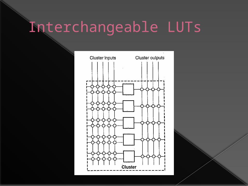
Interchangeable LUTs
Interchangeability
Not all unused units will be substitutable, as location strongly affects interconnections to other logic blocks
Preferable to have fewer large pools of mostly interchangeable resources
Cluster-based architectures
Primitive logic components are grouped into coarse-grained clusters
Richness of internal connectivity means large range of potential interconnect patterns
External access to internal test points becomes increasingly difficult as device sizes scale
Cluster I/O are the input and output pins of the cluster
Tile I/O pins include the endpoint of wire segments which can connect to a neighboring tile via programmable interconnect points

Structure

Built-in Self Test
BIST overhead not an issue› Easily inserted and removed by
reconfiguration Test logic inside the FPGA enables test
access to internal components Each BISTER is composed of
› Test pattern generator› Output response analyzer› Two blocks under test
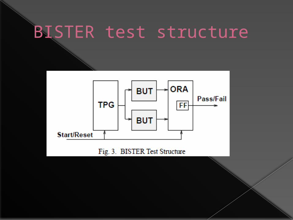
BISTER test structure
BISTER
BIST strategy
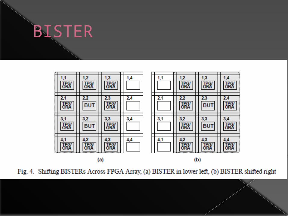
To guarantee testing of all tiles, the FPGA is reconfigured to shift the BISTERs across the entire array› All tiles will be tested by acting as a BUT
Perimeter tiles are tested by using the I/O pads to access the periphery
Total test application time is related to the area of the TPG/ORA logic
Decomposes the problem into many identical problems of a size which is determined by the test requirements for a single tile
Interconnect Fault Detection
High density of internal cluster interconnect makes test access difficult
Must test intra-cluster interconnect and extra-cluster interconnect
Four classes of faults› Permanent connection
PIP off› Permanent disconnection
PIP on› Stuck-at 0› Stuck-at 1
Detection and Diagnosis
Defines testability and diagnosis requirements of each fault and fault pair
Some test pattern must exist to detect each fault and differentiate each fault pair
All LUTs are configured as 4 input XOR gates
The detectability of each fault can be expressed as a function of the tile I/O

Fault Detection Conditions
Faulty line segment s1 must be both controllable by at least one tile input and observable by at least one tile output

Fault Detection Conditions (con’t)
A faulty pair of segments must be both controllable, separately controllable, and both observable
The PIP between the two segments must be switched off
Fault Detection Conditions (con’t)
If s2 is the floating segment, then the non-floating segment must be controllable and the floating segment must be observable
PIP between the two segments must be switched on

Interconnect Fault Equivalence
Equivalent faults cannot be differentiated Fault equivalence is determined by the FPGA
configuration› Faults that are equivalent in one configuration may not be
equivalent in another Maximum diagnostic resolution is achieved when every
pair of faults is non-equivalent in at least one configuration
Two faults are equivalent if their corresponding faulty machines produce the same output with all possible test patterns, at all outputs of the circuit
Two segments are test equivalent in a configuration if the segments have identical control sets and identical observe sets
Interconnect Fault Equivalence (con’t)
Two segments are test equivalent when they are controlled by the same set of tile inputs and observed by the same set of tile outputs
Interconnect Fault Equivalence (con’t)
Each segment in a faulty segment pair must be test equivalent to a segment in the other faulty segment pair
Interconnect Fault Equivalence (con’t)
Pair of faults may be equivalent if a segment which is not driven by a signal floats to a ‘v’ value
The two faults are equivalent if the floating segment is test equivalent to the segment associated with the stuck-at ‘v’ fault
The segment with the stuck-at fault and the floating segment must be controlled by the same set of tile inputs and observed by the same set of tile outputs
Interconnect Fault Equivalence (con’t)
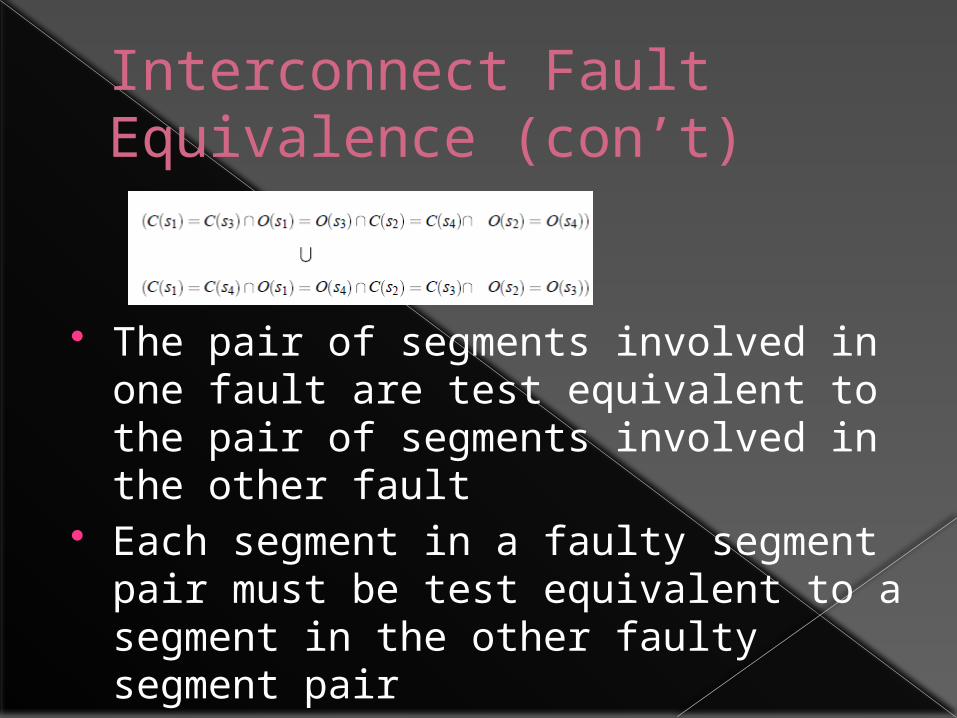
The pair of segments involved in one fault are test equivalent to the pair of segments involved in the other fault
Each segment in a faulty segment pair must be test equivalent to a segment in the other faulty segment pair
Test Configurations
Identifies a set of configurations for the tiles acting as BUTs in a BISTER
Size of configuration should be minimized to reduce test application time
Intra-cluster configurations are defined separately from extra-cluster configurations
Intra-Cluster Configurations
Fault effect on a cluster input must propagate to at least one cluster output
Cluster outputs must be separately controllable
BLE configurations
Observability of cluster inputs and BLE output branches must be achieved by propagating fault effects
Controllability of the BLE outputs must be achieved through the BLEs
Each BLE is composed of a LUT and a multiplexer› Both must be configured› Each LUT acts as a 4-input XOR gate› Good controllability because output value can be determined
by controlling any single input› Good observability because a fault effect on any input will
propagate to output Majority of test configurations bypass the flip-flop
› A single configuration will test the interconnect associated with the flip-flops
BLE input multiplexer configurations
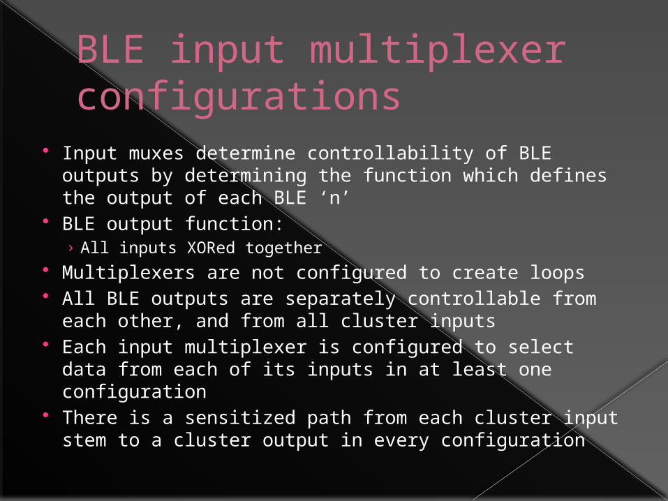
Input muxes determine controllability of BLE outputs by determining the function which defines the output of each BLE ‘n’
BLE output function:› All inputs XORed together
Multiplexers are not configured to create loops All BLE outputs are separately controllable from
each other, and from all cluster inputs Each input multiplexer is configured to select data
from each of its inputs in at least one configuration There is a sensitized path from each cluster input
stem to a cluster output in every configuration
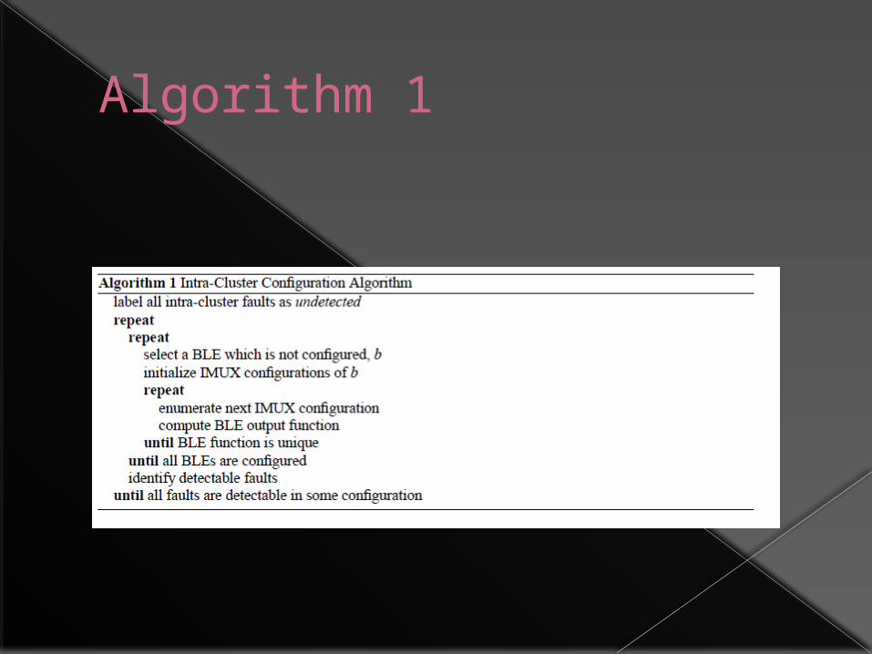
Algorithm 1
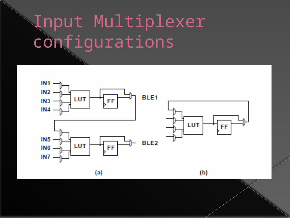
Input Multiplexer configurations
Extra-Cluster Configurations
Defines current flow paths through the extra-cluster interconnect
Modeled as a flow graph Create flow paths between tile I/O nodes
which allow the detection criteria of each fault to be satisfied in at least one configuration
Flow paths are created from tile I/Os to every cluster input, and from every cluster output to tile I/Os

Transparent Extra-Cluster Configuration

Algorithm 2
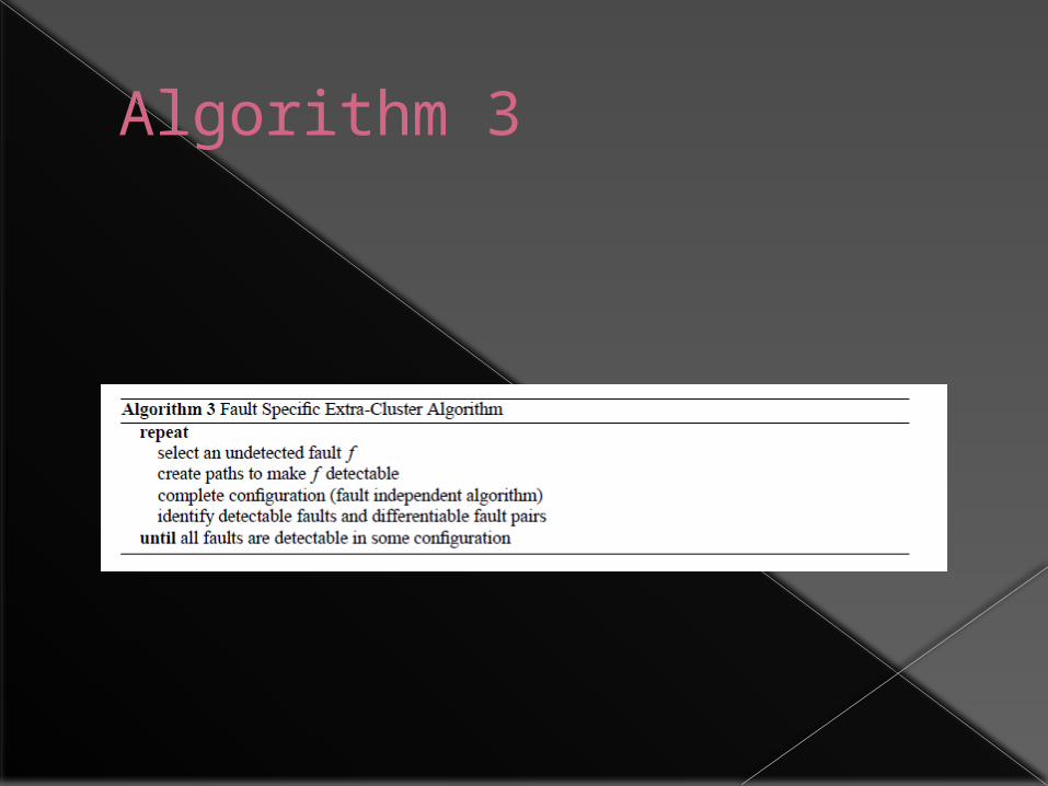
Algorithm 3
Results
Assumptions› Cluster inputs and outputs are equally distributed around the sides of the
cluster› Each cluster I/O on the north face may connect to all horizontal tracks via a set
of PIPs› West face I/O connects to all vertical tracks› Cluster I/O for east and south faces connect directly to tracks in neighboring
tiles Results
› Intra-cluster configuration, and two sets of extra-cluster configuration Extra-Cluster (specific) is for when the fault independent algorithm has reached its
coverage limit› By using the fault specific extra-cluster configuration algorithm, 100% fault
coverage can be guaranteed At a cost of increased number of configurations
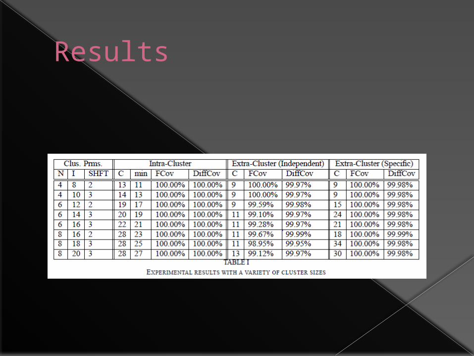
› Fault Coverage Achieved› Percent of fault pairs which are differentiated across all configurations
A small set of test configurations can detect and diagnose nearly all targeted interconnect faults
Results
Summary
Approach is encompassing, can guarantee 100% fault detection› Does require good deal of computation time for
extra-cluster Does a good job of describing fault classes
› I personally believe they could have described it using less mathematical jargon, so that it would make more sense to a digital logic engineer
Algorithms are described neatly in pseudocode
All details are covered

Discussion topics
Section 2
Discussion #1
Let’s discuss the logical ways to test circuitry for the various faults› Permanent open› Permanent closed› Stuck-at 0› Stuck-at 1
How could you design test patterns without access to all internal signals?

Discussion #2
Algorithms› Intra-cluster› Extra-cluster
Discussion #3
Defect mapping Annealing placers
› Marks physical location of defective units as Costly Invalid
Routers› Marks wires and switches that are defective as
In use High cost
Avoids these defective components of the FPGA
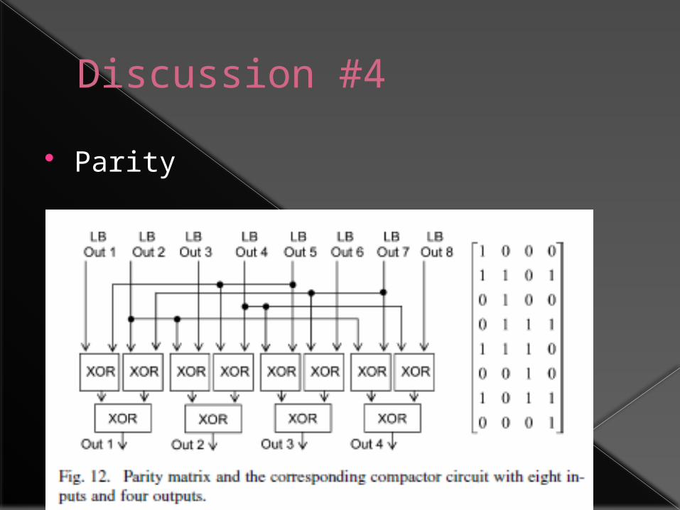
Discussion #4
Parity