SECTION 1 GENERAL INFORMATION - srpnet.com€¦ · Certificate In-Lieu of Electrical Clearance ......
38
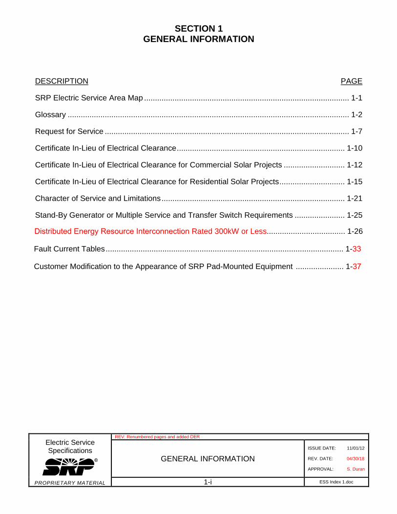
SECTION 1 GENERAL INFORMATION Electric Service Specifications PROPRIETARY MATERIAL REV: Renumbered pages and added DER GENERAL INFORMATION ISSUE DATE: 11/01/12 REV. DATE: 04/30/18 APPROVAL: S. Duran 1-i ESS Index 1.doc DESCRIPTION PAGE SRP Electric Service Area Map .............................................................................................. 1-1 Glossary ................................................................................................................................. 1-2 Request for Service ................................................................................................................ 1-7 Certificate In-Lieu of Electrical Clearance ............................................................................. 1-10 Certificate In-Lieu of Electrical Clearance for Commercial Solar Projects ............................ 1-12 Certificate In-Lieu of Electrical Clearance for Residential Solar Projects .............................. 1-15 Character of Service and Limitations .................................................................................... 1-21 Stand-By Generator or Multiple Service and Transfer Switch Requirements ....................... 1-25 Distributed Energy Resource Interconnection Rated 300kW or Less.................................... 1-26 Fault Current Tables ............................................................................................................. 1-33 Customer Modification to the Appearance of SRP Pad-Mounted Equipment ...................... 1-37
Transcript of SECTION 1 GENERAL INFORMATION - srpnet.com€¦ · Certificate In-Lieu of Electrical Clearance ......
SECTION 1 GENERAL INFORMATION
Electric Service Specifications
PROPRIETARY MATERIAL
REV: Renumbered pages and added DER
GENERAL INFORMATION
ISSUE DATE: 11/01/12
REV. DATE: 04/30/18
APPROVAL: S. Duran
1-i ESS Index 1.doc
DESCRIPTION PAGE
SRP Electric Service Area Map .............................................................................................. 1-1
Glossary ................................................................................................................................. 1-2
Request for Service ................................................................................................................ 1-7
Certificate In-Lieu of Electrical Clearance ............................................................................. 1-10
Certificate In-Lieu of Electrical Clearance for Commercial Solar Projects ............................ 1-12
Certificate In-Lieu of Electrical Clearance for Residential Solar Projects .............................. 1-15
Character of Service and Limitations .................................................................................... 1-21
Stand-By Generator or Multiple Service and Transfer Switch Requirements ....................... 1-25
Distributed Energy Resource Interconnection Rated 300kW or Less.................................... 1-26
Fault Current Tables ............................................................................................................. 1-33
Customer Modification to the Appearance of SRP Pad-Mounted Equipment ...................... 1-37
1-1
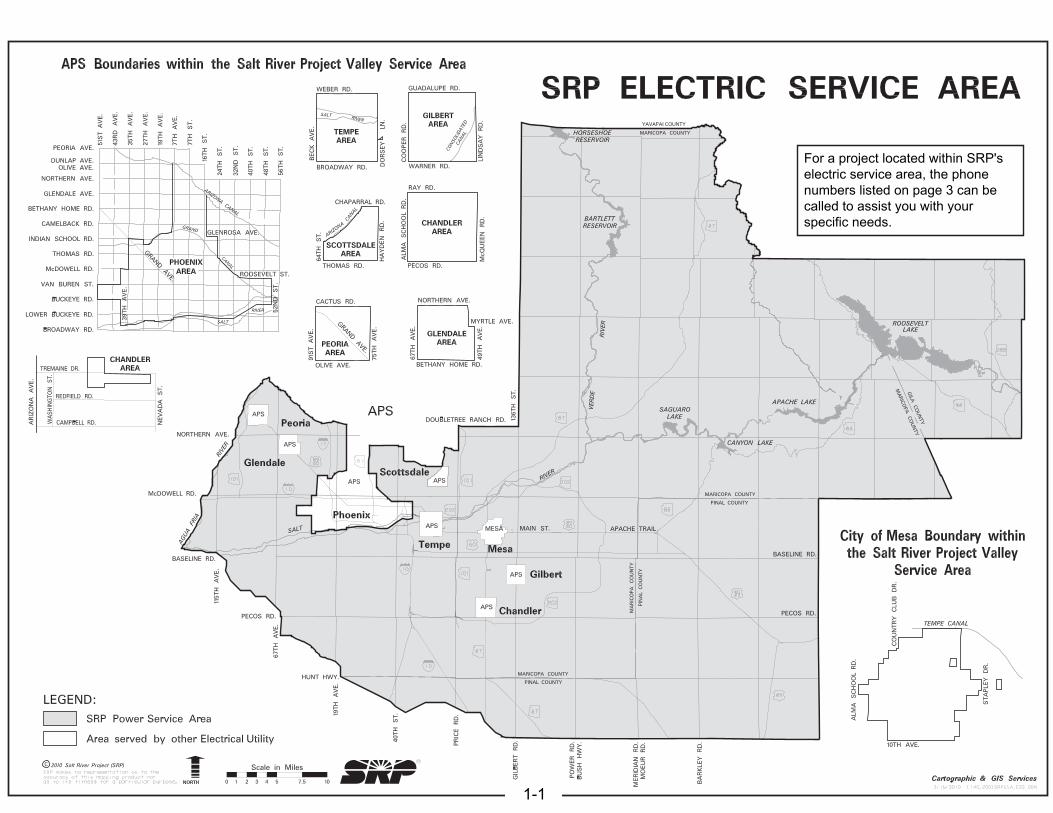
For a project located within SRP'selectric service area, the phonenumbers listed on page 3 can becalled to assist you with yourspecific needs.
GLOSSARY
The following terms, when used herein, shall have the meaning specified.
Electric Service Specifications
PROPRIETARY MATERIAL
REV: Added DER definitions #16, 17 and 18.
GENERAL INFORMATION
GLOSSARY
ISSUE DATE: 04/15/86
REV. DATE: 04/30/18
APPROVAL: S. Duran
1-2 ESS Glossary.doc
1. Available Interrupting Current (AIC): Minimum breaker fault current interrupting capability.
2. All-In-One Service Entrance Section (SES): Equipment manufactured as one unit.
3. American Wire Gauge (AWG): The AWG assigns a number to a particular size of wireaccording to circular mill area to a maximum size of #0000.
4. Authority Having Jurisdiction (AHJ): Governmental agencies and municipalities havingresponsibility for public safety.
5. Blue Stake Law: Arizona Revised Statutes, Chapter 2, Article 6.3, Sections 40-360.21through 40-360.32.
6. Building: A structure that stands alone or is separated from adjoining structures by fire walls(minimum two-hour rated) with all openings therein protected by fire doors.
7. Campus: Customer location having multiple buildings served by multiple SES that is notseparated by private or public property or right-of-way and must be operated as one integralunit with all accounts in a single common entity name.
8. Channel: Pre-manufactured metal framing with compatible fasteners.
9. Coincident Load: The total demand placed on SRP’s distribution system by the SES underconsideration during a 30-minute time interval as recorded in SRP’s billing system.
10. Contributions In Aid Of Construction (CIAC): Financial contributions provided by theCustomer for construction of electrical facilities.
11. Cost or Expense: The cost of all materials and equipment, labor and other definite chargesapplicable thereto, plus a reasonable percentage for engineering, purchasing, the use ofconstruction equipment and other costs of a general character, involved in connection with thework to be performed.
12. Critical Load: Load that cannot be readily disconnected due to public health and/or safetyconcerns.
13. Customer: Any person utilizing services from SRP.
14. Customer-Owned Services: A service lateral provided, installed, owned and maintained bythe Customer, complying with the authority having jurisdiction, where the point of delivery isusually the secondary bushings of the supplying transformer.
15. Distribution Design: The SRP group responsible for design of intended electrical facilities.
16. Distributed Energy Resource (DER): Independent electricity generating or storagetechnologies interconnected to SRP’s distribution system.
17. Distributed Energy Resource (DER) Generation: The generation of electricity via adistributed energy resource (photovoltaic systems, wind generation, etc.).
85
09
E3
16
.DG
N
GLOSSARY
The following terms, when used herein, shall have the meaning specified.
Electric Service Specifications
PROPRIETARY MATERIAL
REV: Added DER definitions #16, 17 and 18.
GENERAL INFORMATION
GLOSSARY
ISSUE DATE: 04/15/86
REV. DATE: 04/30/18
APPROVAL: S. Duran
1-3 ESS Glossary.doc
18. Distributed Energy Resource (DER) Storage: The storage of electricity either drawn fromthe grid or from a DER generation source.
19. Electric Service Specifications (ESS): An SRP manual intended as a guide for makingelectrical installations or modifications, while protecting the interests of the Customer andcomplying with regulations, which experience has shown, are necessary for safe, adequateand satisfactory service. These standards are also available online atsrpnet.com/electric/business/specs/Default.aspx.
20. Electrical Clearance: The approval of an electrical installation by the city or county havingjurisdiction as an indication of compliance with its standards.
21. Electronic Marker: A passive antenna, which is installed over underground facilities that usesan electronic transmitter to allow future location of these facilities.
22. Electrical Metallic Tubing (EMT): A non-flexible, non-corrugated raceway designedspecifically for electrical cables. Also commonly called thin-wall.
22. Electric Utility Service Equipment Requirements Committee (EUSER or EUSERC):Organization comprised of utility representatives from the Western Section of the UnitedStates, which works to promote the standardization of electric service requirements and thedesign and engineering of metering and service equipment. SRP is a participating member.
23. Fault Current: The available short circuit current typically calculated at the Customer’sservice entrance section (see AIC and Isc).
22. Factory Built Building: see Manufactured Building.
23. Gas: Any volatile flammable substance capable of being ignited by an electrical spark.
24. General Public Area: An area where the general public has free access.
25. Ground: A conducting connection between an electrical circuit or equipment and earth, orsome conducting body which serves in place of the earth.
26. Ground Rod: A ground electrode (rod) driven into earth to provide a base reference forvoltage and a path to ground for fault current.
27. Handles, Lifting: Handles attached to meter and service equipment panels to aid in the panelremoval replacement and open/close operation. They are to be non-folding grasp type,designed to provide full, secure attachment and having the ability to withstand stress of a 75pound load.
28. Hand Tools: Tools used to excavate in a safe and prudent manner. Excavation within a zoneidentified as containing underground facilities should be performed with reasonable care usinghand tools (i.e., hand shovels, vacuum excavation methods, soft digging, pot holing or othernon-invasive methods). Hand digging and non-invasive methods are not required forpavement removal.
29. Hipot: A dielectric withstanding voltage test, a hipot test stresses the insulation of an electricalassembly by applying a voltage much higher than is usually experienced in normal operation.The purpose of a hipot test is to assure safety and reliability.
GLOSSARY
The following terms, when used herein, shall have the meaning specified.
Electric Service Specifications
PROPRIETARY MATERIAL
GENERAL INFORMATION
GLOSSARY
ISSUE DATE: 04/15/86 REV. DATE: 09/06/17 APPROVAL: N. Sabbah
1-4 ESS Glossary.doc
30. Instrument Transformer: A device that is intended to reproduce in its secondary circuit, in a definite and known proportion suitable for utilization in measurement, control, or protective devices, the current (or voltage) of its primary circuit, with its phase relations substantially preserved. Types include: Potential (voltage), Transformers (PT), and Current Transformers (CT).
31. Isc: Available utility fault current for arc flash study.
32. Junction Box (J-Box): An above ground surface or sub-surface box which houses cable connections. It may be a Customer’s point of delivery.
33. kCMIL (kCM): The size of any wire larger than 4/0 is expressed directly in circular mil area. Example: 250,000 Circular Mils = 250 MCM
34. Line: A system of poles, ducts, wires or fixtures used for the transmission and distribution of electricity.
35. Load: The ratings of the power consuming apparatus which may be connected to SRP’s installation or system under consideration.
36. Main Line Trench: Any trench located in road right-of-way (by permit), public utility easement or private easement that contains electrical facilities.
37. Manufactured Building: Any building that is of closed construction and is made or assembled in manufacturing facilities on or off the building site for installation, or for assembly and installation on the building site, other than manufactured homes, mobile homes, park trailers, or recreational vehicles.
38. Manufactured Home: A structure that is transportable in one or more sections and is 2.5 m (8 body ft.) or more in width or 12 m (40 body ft.) or more in length in the traveling mode, or when erected on site is 30m2 (320 ft2) or more; which is built on a chassis and designed to be used as a dwelling, with or without a permanent foundation, when connected to the required utilities, including the plumbing, heating, air conditioning, and electrical systems contained therein.
39. MCM (Thousand Circular Mills, ALSO KCMIL): See kCMIL.
40. Meter Pedestal: Self-supported underground service entrance section.
41. Mobile Home: For the purposes of the standards and code, see Manufactured Home.
42. Modification: Change in ampacity, change in character of service, added load, relocation or conversion of an existing service entrance section. Distribution Design and the authority having jurisdiction must approve all modifications. All modifications must comply with the current Electric Service Specifications and any other applicable standards.
43. Municipality: A state, local, or federal government entity, excluding Native American communities.
44. National Electrical Code (NEC): Published by the National Fire Protection Association (NFPA) as NFPA-70, addresses proper electrical systems and equipment installation to protect people and property from hazards arising from the use of electricity in buildings and
GLOSSARY
The following terms, when used herein, shall have the meaning specified.
Electric Service Specifications
PROPRIETARY MATERIAL
GENERAL INFORMATION
GLOSSARY
ISSUE DATE: 04/15/86
REV. DATE: 09/06/17
APPROVAL: N. Sabbah
1-5 ESS Glossary.doc
structures. SRP considers the NEC to be the minimum acceptable standard. City, county, or authority having jurisdiction requirements that are more stringent shall prevail.
45. National Electrical Safety Code (NESC): The purpose of the NESC is the practicalsafeguarding of persons during the installation, operation, or maintenance of electric supplyand communication lines and associated equipment. It is a nationally accepted codegoverning utility wiring.
46. Non-Critical Load: A load that, if interrupted, will not cause personal injury or propertydamage, as defined by SRP Design.
47. Parallel Generation: Electrical generation equipment that has been approved by SRP tooperate interconnected with SRP’s electrical system.
48. Pedestal, Box: See Junction Box.
49. Phase Rotation: A-B-C counterclockwise. For a group of Customers measured at thetransformer secondary or for a single Customer measured at the Customer’s service entrance.
50. Point Of Attachment: The point at which restraining or anchoring contact is made betweenSRP’s facilities and those of the Customer. This is strictly a mechanical consideration anddoes not necessarily imply any separation of responsibilities.
51. Point Of Delivery (POD): The point of interconnection between SRP’s electrical facilities andthose of the Customer. It is the exact point at which the separation of responsibility occurs forthe construction, ownership, operation and maintenance of all facilities except meteringequipment. SRP will determine the POD in all cases.
52. Power Leg (Wild Leg): The “C” (third) phase of a four-wire delta secondary that is marked“blue with an orange tracer”.
53. Preferred: Recommended but not required.
54. Public Agency: Any organization that is publicly or taxpayer funded.
55. Public Utility Easement (PUE): An easement for overhead or underground utility facilitiesprovided for the use of the public, including water, storm drainage, sewage, electricity andcommunication, owned and operated by any person, firm, corporation, municipal department,or board duly authorized by state or municipal regulations. Utility or utilities as used hereinrefer to such person, firms, corporations, departments, or boards.
56. Public Utility Facility Easement (PUFE): An easement for the installation of facilities,underground or overhead, furnished for the use of the public, including electricity, gas, steam,communication, water, storm drainage, sewage, sidewalks, landscaping, traffic signals, streetlights, flood control, etc., owned and operated by any person, firm, corporation, municipaldepartment, or board duly authorized by state or municipal regulations. Utility or utilities asused herein may also refer to such person, firms, corporations, departments, or boards.
57. Photovoltaic: PV
58. Readily Accessible: Capable of being reached directly, without obstruction at any time. Seealso Metering section, Service Entrance Section, Equipment Rooms.
GLOSSARY
The following terms, when used herein, shall have the meaning specified.
Electric Service Specifications
PROPRIETARY MATERIAL
GENERAL INFORMATION
GLOSSARY
ISSUE DATE: 04/15/86 REV. DATE: 09/06/17 APPROVAL: N. Sabbah
1-6 ESS Glossary.doc
59. Right-of-Way (ROW): The right to build and operate a utility on land belonging to another.
60. Salt River Project (SRP): Agricultural Improvement and Power District.
61. Securely Attached: Attached to withstand anticipated loads not subject to loosening.
62. Service Connection: One service lateral and its associated service entrance.
63. Service Drop: Refer to Service Lateral.
64. Service Energization: The connection of a service to a voltage source.
65. Service Entrance Section (SES): The part of the installation from the point of attachment or termination of the service lateral to and including the service equipment on the Customer’s premises.
66. Service Equipment: The necessary electrical facilities, usually consisting of a circuit breaker or switch and fuses, conductors and accessories, which constitute the main control and cutoff of the electric supply, and which are installed, owned and maintained by the Customer.
67. Service Lateral: A system of wires, fixtures and sometimes poles, or the equivalent ducts, conduits and cables used to conduct electricity from an electrical source to the point of delivery.
68. Service Trench: The trench on property containing the service to the home or business.
69. Solar Ready: A service entrance panel with a dedicated breaker installed by the manufacturer, allowing the attachment of a Customer’s 60 Hz AC solar voltaic feed, via the Customer’s utility AC disconnect switch and photovoltaic meter, resulting in a supply side tap configuration.
70. Temporary Service: Short-term, non-recurring service of a transitory character, as determined solely by SRP, which may include in its evaluation the speculative character or questionable permanency of the Customer’s operations.
71. Totalized Metering and/or Totalizing: The measurement of the simultaneous demands and energy of a Customer who receives electric service at more than one service entrance section at a single site or campus for billing purposes on the appropriate price plan.
72. Trapped Key Interlock System: A safety device applied to two operating devices, which prevents them from being simultaneously in a closed position.
73. Ufer: A concrete-encased electrode, generally located in the foundation of a building, used for grounding the building.
74. Underwriters Laboratory (UL): An independent laboratory facility for testing all types of electrical equipment.
75. Weatherhead: A metal cap on a Customer’s service entrance section that protects the connection of SRP’s overhead service conductors to the Customer’s conductors from adverse weather conditions.
76. Wild Leg: See Power Leg.
REQUEST FOR SERVICE
Electric Service Specifications
PROPRIETARY MATERIAL
GENERAL INFORMATION
REQUEST FOR SERVICE
ISSUE DATE: 04/15/86
REV. DATE: 11/09/12
APPROVAL: W. Laramie
1-7 ESS RequestforSvc.doc
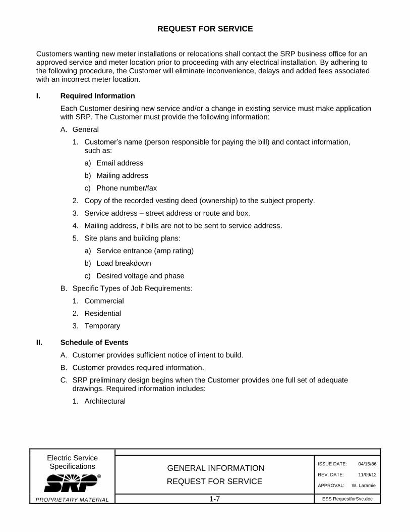
Customers wanting new meter installations or relocations shall contact the SRP business office for an approved service and meter location prior to proceeding with any electrical installation. By adhering to the following procedure, the Customer will eliminate inconvenience, delays and added fees associated with an incorrect meter location.
I. Required Information
Each Customer desiring new service and/or a change in existing service must make application with SRP. The Customer must provide the following information:
A. General
1. Customer’s name (person responsible for paying the bill) and contact information,such as:
a) Email address
b) Mailing address
c) Phone number/fax
2. Copy of the recorded vesting deed (ownership) to the subject property.
3. Service address – street address or route and box.
4. Mailing address, if bills are not to be sent to service address.
5. Site plans and building plans:
a) Service entrance (amp rating)
b) Load breakdown
c) Desired voltage and phase
B. Specific Types of Job Requirements:
1. Commercial
2. Residential
3. Temporary
II. Schedule of Events
A. Customer provides sufficient notice of intent to build.
B. Customer provides required information.
C. SRP preliminary design begins when the Customer provides one full set of adequatedrawings. Required information includes:
1. Architectural
REQUEST FOR SERVICE
Electric Service Specifications
PROPRIETARY MATERIAL
GENERAL INFORMATION
REQUEST FOR SERVICE
ISSUE DATE: 04/15/86
REV. DATE: 11/09/12
APPROVAL: W. Laramie
1-8 ESS RequestforSvc.doc
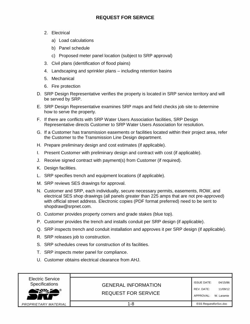
2. Electrical
a) Load calculations
b) Panel schedule
c) Proposed meter panel location (subject to SRP approval)
3. Civil plans (identification of flood plains)
4. Landscaping and sprinkler plans – including retention basins
5. Mechanical
6. Fire protection
D. SRP Design Representative verifies the property is located in SRP service territory and will be served by SRP.
E. SRP Design Representative examines SRP maps and field checks job site to determine how to serve the property.
F. If there are conflicts with SRP Water Users Association facilities, SRP Design Representative directs Customer to SRP Water Users Association for resolution.
G. If a Customer has transmission easements or facilities located within their project area, refer the Customer to the Transmission Line Design department.
H. Prepare preliminary design and cost estimates (if applicable).
I. Present Customer with preliminary design and contract with cost (if applicable).
J. Receive signed contract with payment(s) from Customer (if required).
K. Design facilities.
L. SRP specifies trench and equipment locations (if applicable).
M. SRP reviews SES drawings for approval.
N. Customer and SRP, each individually, secure necessary permits, easements, ROW, andelectrical SES shop drawings (all panels greater than 225 amps that are not pre-approved) with official street address. Electronic copies (PDF format preferred) need to be sent to [email protected].
O. Customer provides property corners and grade stakes (blue top).
P. Customer provides the trench and installs conduit per SRP design (if applicable).
Q. SRP inspects trench and conduit installation and approves it per SRP design (if applicable).
R. SRP releases job to construction.
S. SRP schedules crews for construction of its facilities.
T. SRP inspects meter panel for compliance.
U. Customer obtains electrical clearance from AHJ.
REQUEST FOR SERVICE
Electric Service Specifications
PROPRIETARY MATERIAL
GENERAL INFORMATION
REQUEST FOR SERVICE
ISSUE DATE: 04/15/86
REV. DATE: 11/09/12
APPROVAL: W. Laramie
1-9 ESS RequestforSvc.doc
V. Once an account has been established with SRP and clearance has been received from AHJ, the service lateral will be energized and installation of the meter scheduled. SRP must be contacted to provide a meter. The SES must stay in compliance with ESS requirements.
III. Temporary Service
Go to srpnet.com/service/business/tempservice.aspx or call 602-236-0777.
IV. Panel Modifications and/or Repair
Contact both SRP and the AHJ prior to making any panel modifications and/or repair to anexisting service entrance section. SRP will reconnect power when both SRP and the AHJapprove all service entrance section modifications.
V. Codes
These specifications are a supplement to the NEC but they are not a substitute for that code or for codes of the AHJ. SRP endorses the jurisdictional authority’s right to inspect and insure that the Customer’s wiring installations be made in accordance with applicable codes.
VI. Inspections, Approvals and Permits
Refer to the map on page 1-1 and contact information on page 3 for the appropriate SRPbusiness office.
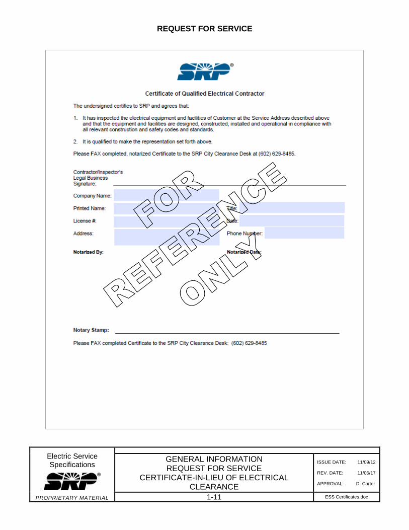
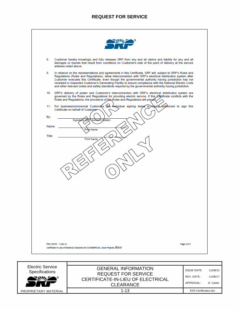
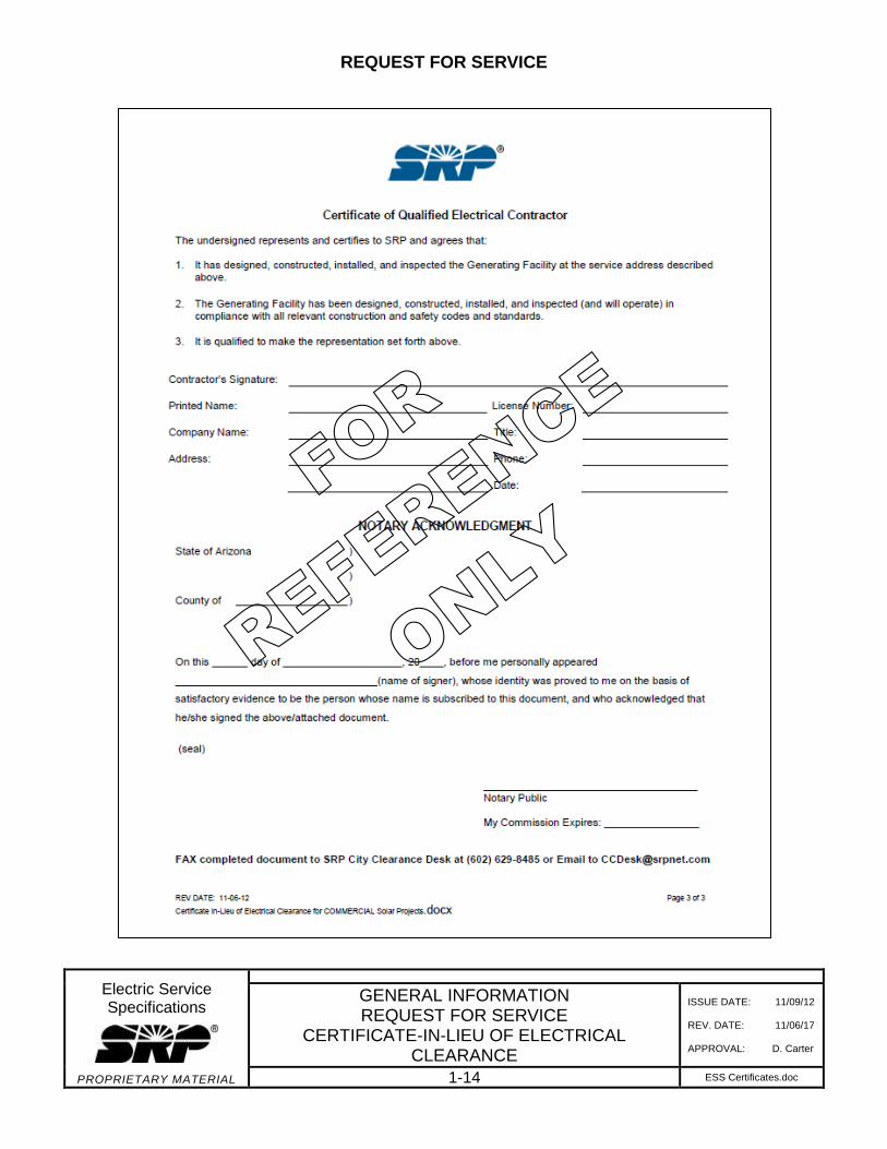
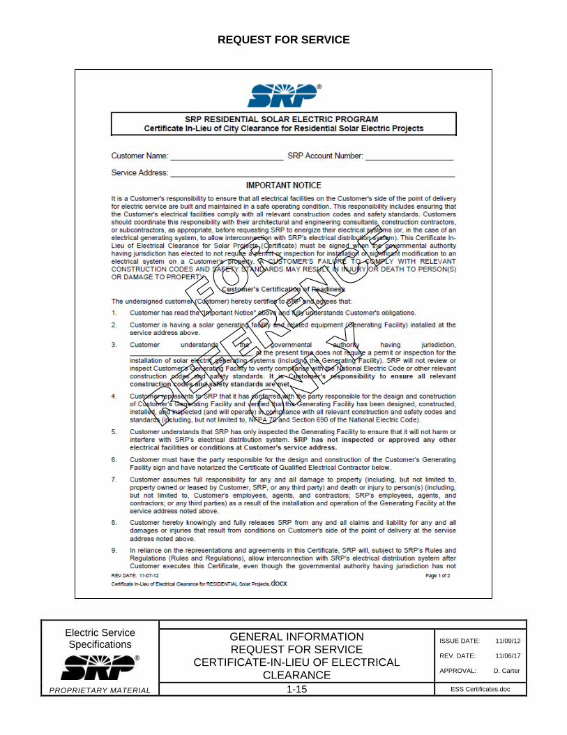
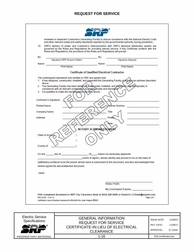
Maricopa County and most cities/towns in SRP’s service area have ordinances restricting SRPfrom energizing the load side of the electrical service to the Customer until the Customer hasobtained the necessary permits and until the actual electrical installation has been approved bythe AHJ. Therefore, the Customer should determine the requirements of the BuildingSafety/Building Inspection department of the county or city having jurisdiction before beginningany job subject to inspection by that department. If no jurisdictional authority exists, SRP mustreceive a certificate in-lieu of electrical clearance, including the notarized signature and licensenumber of the qualified electrical contractor, stating that the facility meets the NEC requirementsprior to receiving SRP’s electrical service.
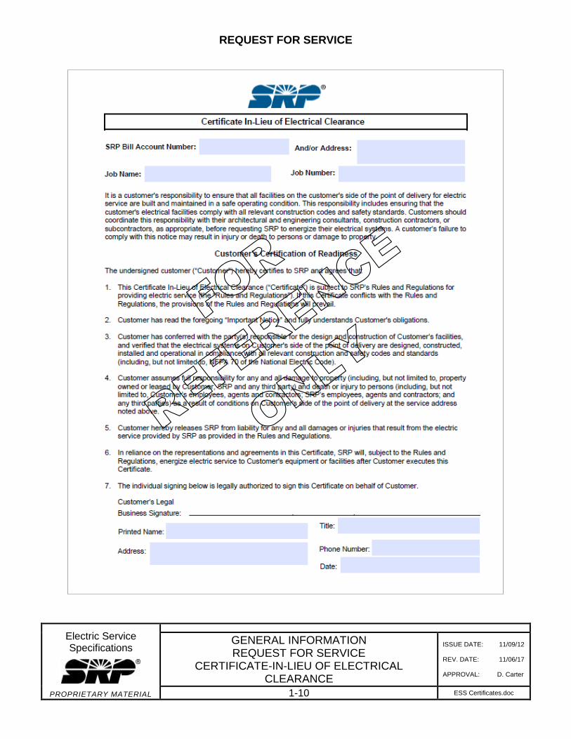
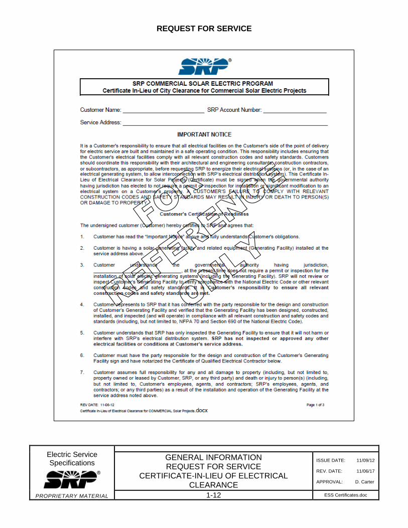
Reference copies of the Certificate In-Lieu of Electrical Clearance and the Certificate In-Lieu ofElectrical Clearance for Solar Projects are provided on the following pages. Contact SRPDesign via the appropriate SRP business office to obtain a copy of these forms.
REQUEST FOR SERVICE
Electric Service Specifications
PROPRIETARY MATERIAL
GENERAL INFORMATION REQUEST FOR SERVICE
CERTIFICATE-IN-LIEU OF ELECTRICAL CLEARANCE
ISSUE DATE: 11/09/12
REV. DATE: 11/06/17
APPROVAL: D. Carter
1-10 ESS Certificates.doc
REQUEST FOR SERVICE
Electric Service Specifications
PROPRIETARY MATERIAL
GENERAL INFORMATION REQUEST FOR SERVICE
CERTIFICATE-IN-LIEU OF ELECTRICAL CLEARANCE
ISSUE DATE: 11/09/12
REV. DATE: 11/06/17
APPROVAL: D. Carter
1-11 ESS Certificates.doc
REQUEST FOR SERVICE
Electric Service Specifications
PROPRIETARY MATERIAL
GENERAL INFORMATION REQUEST FOR SERVICE
CERTIFICATE-IN-LIEU OF ELECTRICAL CLEARANCE
ISSUE DATE: 11/09/12
REV. DATE: 11/06/17
APPROVAL: D. Carter
1-12 ESS Certificates.doc
REQUEST FOR SERVICE
Electric Service Specifications
PROPRIETARY MATERIAL
GENERAL INFORMATION REQUEST FOR SERVICE
CERTIFICATE-IN-LIEU OF ELECTRICAL CLEARANCE
ISSUE DATE: 11/09/12
REV. DATE: 11/06/17
APPROVAL: D. Carter
1-13 ESS Certificates.doc
REQUEST FOR SERVICE
Electric Service Specifications
PROPRIETARY MATERIAL
GENERAL INFORMATION REQUEST FOR SERVICE
CERTIFICATE-IN-LIEU OF ELECTRICAL CLEARANCE
ISSUE DATE: 11/09/12
REV. DATE: 11/06/17
APPROVAL: D. Carter
1-14 ESS Certificates.doc
REQUEST FOR SERVICE
Electric Service Specifications
PROPRIETARY MATERIAL
GENERAL INFORMATION REQUEST FOR SERVICE
CERTIFICATE-IN-LIEU OF ELECTRICAL CLEARANCE
ISSUE DATE: 11/09/12
REV. DATE: 11/06/17
APPROVAL: D. Carter
1-15 ESS Certificates.doc
REQUEST FOR SERVICE
Electric Service Specifications
PROPRIETARY MATERIAL
GENERAL INFORMATION REQUEST FOR SERVICE
CERTIFICATE-IN-LIEU OF ELECTRICAL CLEARANCE
ISSUE DATE: 11/09/12
REV. DATE: 11/06/17
APPROVAL: D. Carter
1-16 ESS Certificates.doc
REQUEST FOR SERVICE
Electric Service Specifications
PROPRIETARY MATERIAL
GENERAL INFORMATION
REQUEST FOR SERVICE
ISSUE DATE: 04/15/86
REV. DATE: 10/19/12
APPROVAL: W. Laramie
1-17 ESS1-17to1-20.doc
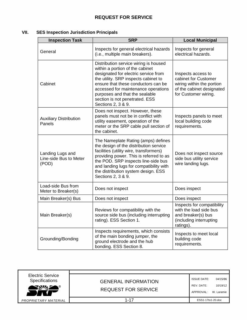
VII. SES Inspection Jurisdiction Principals
Inspection Task SRP Local Municipal
General Inspects for general electrical hazards (i.e., multiple main breakers).
Inspects for general electrical hazards.
Cabinet
Distribution service wiring is housed within a portion of the cabinet designated for electric service from the utility. SRP inspects cabinet to ensure that these conductors can be accessed for maintenance operations purposes and that the sealable section is not penetrated. ESS Sections 2, 3 & 9.
Inspects access to cabinet for Customer wiring within the portion of the cabinet designated for Customer wiring.
Auxiliary Distribution Panels
Does not inspect. However, these panels must not be in conflict with utility easement, operation of the meter or the SRP cable pull section of the cabinet.
Inspects panels to meet local building code requirements.
Landing Lugs and Line-side Bus to Meter (POD)
The Nameplate Rating (amps) defines the design of the distribution service facilities (utility wire, transformers) providing power. This is referred to as the POD. SRP inspects line-side bus and landing lugs for compatibility with the distribution system design. ESS Sections 2, 3 & 9.
Does not inspect source side bus utility service wire landing lugs.
Load-side Bus from Meter to Breaker(s)
Does not inspect Does inspect
Main Breaker(s) Bus Does not inspect Does inspect
Main Breaker(s) Reviews for compatibility with the source side bus (including interrupting rating). ESS Section 1.
Inspects for compatibility with the load side bus and breaker(s) bus (including interrupting ratings).
Grounding/Bonding
Inspects requirements, which consists of the main bonding jumper, the ground electrode and the hub bonding. ESS Section 8.
Inspects to meet local building code requirements.
REQUEST FOR SERVICE
Electric Service Specifications
PROPRIETARY MATERIAL
REV: Added Factory Built Buildings to Inspect Tasks
GENERAL INFORMATION
REQUEST FOR SERVICE
ISSUE DATE: 04/15/86
REV. DATE: 09/06/17
APPROVAL: N. Sabbah
1-18 ESS1-17to1-20.doc
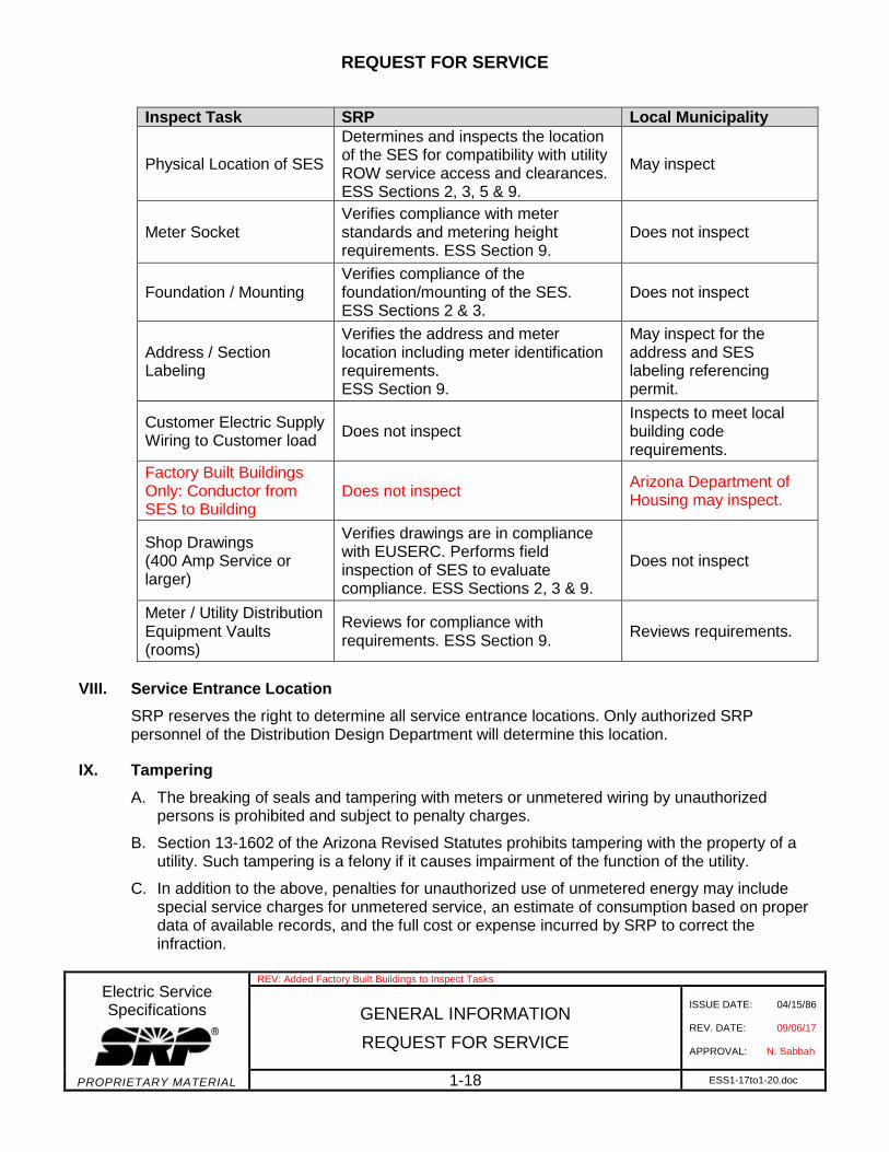
Inspect Task SRP Local Municipality
Physical Location of SES
Determines and inspects the location of the SES for compatibility with utility ROW service access and clearances. ESS Sections 2, 3, 5 & 9.
May inspect
Meter Socket Verifies compliance with meter standards and metering height requirements. ESS Section 9.
Does not inspect
Foundation / Mounting Verifies compliance of the foundation/mounting of the SES. ESS Sections 2 & 3.
Does not inspect
Address / Section Labeling
Verifies the address and meter location including meter identification requirements. ESS Section 9.
May inspect for the address and SES labeling referencing permit.
Customer Electric Supply Wiring to Customer load
Does not inspect Inspects to meet local building code requirements.
Factory Built Buildings Only: Conductor from SES to Building
Does not inspect Arizona Department of Housing may inspect.
Shop Drawings (400 Amp Service or larger)
Verifies drawings are in compliance with EUSERC. Performs field inspection of SES to evaluate compliance. ESS Sections 2, 3 & 9.
Does not inspect
Meter / Utility Distribution Equipment Vaults (rooms)
Reviews for compliance with requirements. ESS Section 9.
Reviews requirements.
VIII. Service Entrance Location
SRP reserves the right to determine all service entrance locations. Only authorized SRPpersonnel of the Distribution Design Department will determine this location.
IX. Tampering
A. The breaking of seals and tampering with meters or unmetered wiring by unauthorizedpersons is prohibited and subject to penalty charges.
B. Section 13-1602 of the Arizona Revised Statutes prohibits tampering with the property of a utility. Such tampering is a felony if it causes impairment of the function of the utility.
C. In addition to the above, penalties for unauthorized use of unmetered energy may include special service charges for unmetered service, an estimate of consumption based on proper data of available records, and the full cost or expense incurred by SRP to correct the infraction.
REQUEST FOR SERVICE
Electric Service Specifications
PROPRIETARY MATERIAL
GENERAL INFORMATION
REQUEST FOR SERVICE
ISSUE DATE: 04/15/86
REV. DATE: 10/19/12
APPROVAL: W. Laramie
1-19 ESS1-17to1-20.doc
X. Responsibility
The Customer has the responsibility to maintain their wiring and equipment in safe operating condition. SRP cannot accept any responsibility for the Customer’s wiring and equipment.
NOTE: SRP gives no warranty, expressed or implied, as to the adequacy, safety or other characteristic of any equipment, wiring or device and assumes no responsibility with respect thereto.
XI. Cooperation
It is the sincere desire of SRP to provide and maintain dependable, safe, and satisfactoryelectric service in a courteous and efficient manner. Cooperation of Customers and their agentsis appreciated. It is necessary to provide SRP with information leading to new or increasedelectric service early in the development of plans to aid the proper scheduling of service.Cooperation of all interested parties and strict adherence to the specifications in the manual willexpedite satisfactory electric service.
XII. Enforcement of Specifications
SRP will allow a 45-day grace period prior to enforcing new or revised specifications placed inthis ESS book.
EXCEPTION: Hazardous or safety-related requirements resulting in new or revised specifications shall be enforced immediately.
XIII. Appeals
SRP has an appeal process. Contact Customer Services for more information.
XIV. Access to Service Entrance Section/Metering on Customer’s Premises
A. The SES/metering, and any other SRP equipment installed on the Customer’s premises,shall be readily accessible by SRP's authorized employees or agents at all times. The Customer shall be required to relocate the SES if SRP access is later restricted by any condition (see Section 5 – Clearances and Section 9 – Metering & SES).
B. Electrically operated gates, which do not permit immediate 24-hour access to electric facilities for SRP personnel, could pose a safety hazard. Every existing or proposed electrically operated gate in SRP territory is required to have the approved SRP Restricted Access Switch assembly installed. Customers are responsible for installing the SRP approved switch, which will be wired to the gate controller, on electrically operated gates. The required lock and key switch will be available through SRP after payment for the lock and switch has been received. The switch will be installed by the Customer’s gate service company and maintained by the Customer, according to SRP specifications. Customers are also required to provide the means of opening gates from the inside without the use of vehicles to activate the controller. This may require the installation of an additional SRP Restricted Access Switch assembly inside the gate if there is not an unsecured switch available for SRP use.
REQUEST FOR SERVICE
Electric Service Specifications
PROPRIETARY MATERIAL
GENERAL INFORMATION
REQUEST FOR SERVICE
ISSUE DATE: 04/15/86
REV. DATE: 10/19/12
APPROVAL: W. Laramie
1-20 ESS1-17to1-20.doc
XV. Tree Trimming
SRP does not prune trees around power lines that run from power poles to homes (on privateproperty), businesses or street lights. In these cases, pruning is the responsibility of the propertyowner. Never attempt to prune trees near power lines yourself! Arizona law placesrestrictions on tree pruning within 10 feet of a power line. A qualified contractor is required.Private contractors must be qualified per OSHA line clearance standards.
NOTE: All vegetation near conductors, pole to pole (in PUE and/or ROW), must be cleared bySRP. Charges may apply.
XVI. Identification of Employees
SRP employees, authorized to visit the Customer’s premises, are furnished with identification,which they will show upon request. This is done to protect the Customer from unauthorizedpersons representing themselves as SRP employees.
XVII. Rate Schedule
Upon request, SRP Rate Schedules and/or Rules and Regulations are available for examinationat any SRP business office or online at srpnet.com.
XVIII. Attachments to SRP Facilities
No attachments are allowed to SRP facilities unless provided by joint use contract.
XIX. SRP Excavations
No joint use with SRP underground facilities unless by joint use contract.
CHARACTER OF SERVICE AND LIMITATIONS
Electric Service Specifications
PROPRIETARY MATERIAL
Note 1.D was revised on ESS 1-22 to indicate the maximum size for a wall-mounted SES
GENERAL
CHARACTER OF SERVICE AND LIMITATIONS
ISSUE DATE: 04/15/86
REV. DATE: 08/08/17
APPROVAL: N. Sabbah
1-21 ESS1-21to1-24.doc
SRP reserves the right to approve all service installations and only authorized personnel of the Distribution Design department will make the determination.
I. Types of Service
A. The following types of service are available based on the classification of use, location and the amount of load to be served. It is necessary for the Customer to contact the regional Distribution Design department to verify availability of the type of service requested prior to purchasing equipment. Typically, SRP will supply one voltage classification to a building. Single-phase service in a three-phase service area will depend on availability of capacity as determined by SRP Design.
B. The operation of large flashing signs, welders, arc furnaces, induction heaters, radio and television transmitters, x-ray equipment, reciprocating compressors and similar apparatus having intermittent flow of large currents sometimes interferes with other users of the electric service. The Customer shall consult SRP so that the character of electric service that will be supplied, the corrective equipment needed and other special precautions that must be taken, will be mutually known factors before planning to use such apparatus. The Customer shall be responsible for corrective equipment that may be necessary.
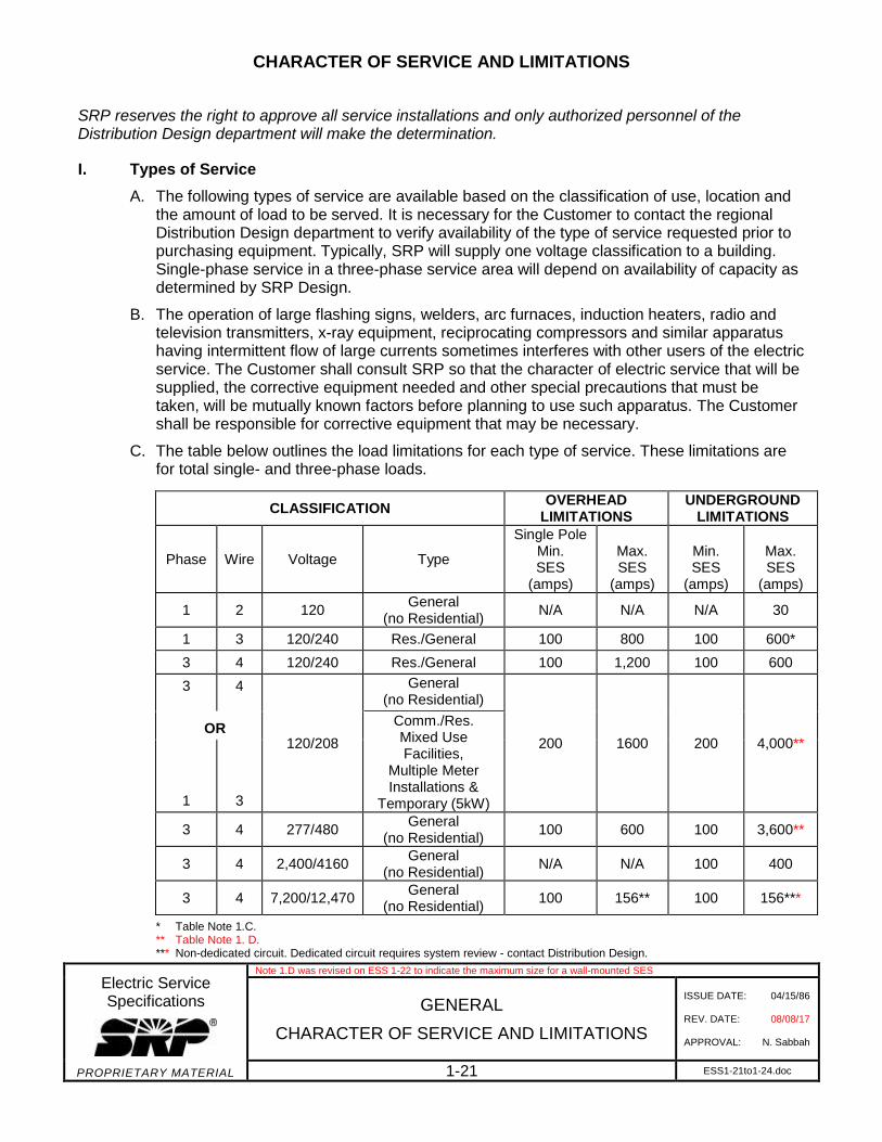
C. The table below outlines the load limitations for each type of service. These limitations are for total single- and three-phase loads.
* Table Note 1.C.** Table Note 1. D. *** Non-dedicated circuit. Dedicated circuit requires system review - contact Distribution Design.
CLASSIFICATION OVERHEAD
LIMITATIONS UNDERGROUND
LIMITATIONS
Phase Wire Voltage Type
Single Pole Min. SES
(amps)
Max. SES
(amps)
Min. SES
(amps)
Max. SES
(amps)
1 2 120 General
(no Residential) N/A N/A N/A 30
1 3 120/240 Res./General 100 800 100 600*
3 4 120/240 Res./General 100 1,200 100 600
3 4
120/208
General (no Residential)
200 1600 200 4,000** OR
Comm./Res. Mixed Use Facilities,
Multiple Meter Installations &
Temporary (5kW) 1 3
3 4 277/480 General
(no Residential) 100 600 100 3,600**
3 4 2,400/4160 General
(no Residential) N/A N/A 100 400
3 4 7,200/12,470 General
(no Residential) 100 156** 100 156***
CHARACTER OF SERVICE AND LIMITATIONS
Electric Service Specifications
PROPRIETARY MATERIAL
Note 1.D was revised on ESS 1-22 to indicate the maximum size for a wall-mounted SES
GENERAL
CHARACTER OF SERVICE AND LIMITATIONS
ISSUE DATE: 04/15/86
REV. DATE: 08/08/17
APPROVAL: N. Sabbah
1-22 ESS1-21to1-24.doc
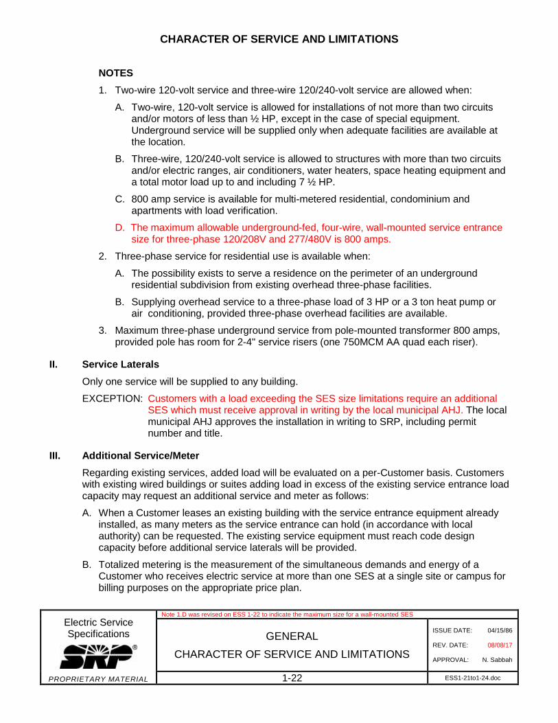
NOTES
1. Two-wire 120-volt service and three-wire 120/240-volt service are allowed when:
A. Two-wire, 120-volt service is allowed for installations of not more than two circuitsand/or motors of less than ½ HP, except in the case of special equipment. Underground service will be supplied only when adequate facilities are available at the location.
B. Three-wire, 120/240-volt service is allowed to structures with more than two circuits and/or electric ranges, air conditioners, water heaters, space heating equipment and a total motor load up to and including 7 ½ HP.
C. 800 amp service is available for multi-metered residential, condominium and apartments with load verification.
D. The maximum allowable underground-fed, four-wire, wall-mounted service entrance size for three-phase 120/208V and 277/480V is 800 amps.
2. Three-phase service for residential use is available when:
A. The possibility exists to serve a residence on the perimeter of an undergroundresidential subdivision from existing overhead three-phase facilities.
B. Supplying overhead service to a three-phase load of 3 HP or a 3 ton heat pump or air conditioning, provided three-phase overhead facilities are available.
3. Maximum three-phase underground service from pole-mounted transformer 800 amps,provided pole has room for 2-4" service risers (one 750MCM AA quad each riser).
II. Service Laterals
Only one service will be supplied to any building.
EXCEPTION: Customers with a load exceeding the SES size limitations require an additionalSES which must receive approval in writing by the local municipal AHJ. The local municipal AHJ approves the installation in writing to SRP, including permit number and title.
III. Additional Service/Meter
Regarding existing services, added load will be evaluated on a per-Customer basis. Customerswith existing wired buildings or suites adding load in excess of the existing service entrance loadcapacity may request an additional service and meter as follows:
A. When a Customer leases an existing building with the service entrance equipment alreadyinstalled, as many meters as the service entrance can hold (in accordance with local authority) can be requested. The existing service equipment must reach code design capacity before additional service laterals will be provided.
B. Totalized metering is the measurement of the simultaneous demands and energy of a Customer who receives electric service at more than one SES at a single site or campus for billing purposes on the appropriate price plan.
CHARACTER OF SERVICE AND LIMITATIONS
Electric Service Specifications
PROPRIETARY MATERIAL
GENERAL
CHARACTER OF SERVICE AND LIMITATIONS
ISSUE DATE: 04/15/86
REV. DATE: 11/07/16
APPROVAL: N. Sabbah
1-23 ESS1-21to1-24.doc
1. General Requirements:
An electrical service Customer whose load requires multiple points of delivery andSES at a single location may be metered and billed as if from a single meter throughtotalized metering, provided all of the following criteria are satisfied:
a) Customer facilities must be located on adjacent contiguous site as per campus.
b) All accounts to be totalized must be on the same E-60 series price plan.
c) Totalized metering may be accomplished by providing electronically totalizeddemand and energy reads.
d) Only three-phase SES are to be combined for totalization.
e) Permissible service voltages are 277/480 or 120/208 three phases, four-wire.
f) The Customer shall provide, at no cost to SRP, vault or transformer spacelocated as designated by SRP and compliant to all clearance and accessrequirements.
g) Customers who operate an electric generation unit on the premise, totalizedmetering will be permitted when the Customer complies with all SRP requirementsfor interconnection, pays all costs for any additional special metering required toaccommodate such service from totalized service sections, and takes service onan applicable price plan for interconnected Customer-owned generation.
h) Written approval by SRP authorized representative is required before totalizedmetering may be implemented.
i) Customer’s metered coincident load exceeds SRP’s ability to serve through onetransformer (two services may be totalized into one when the coincident loadexceeds 2550kVA).
j) The Customer’s SES are within 150 feet of each other. Services connected to adedicated feeder are generally totalized. Dedicated feeders are evaluated on anindividual basis.
Multiple services installed at the request of a Customer for purposes of reliability,redundancy, etc., and which do not otherwise qualify based on coincident load, willnot be totalized.
C. Removal of totalized metering configuration (some or all) shall be permitted provided all of the following criteria are satisfied:
1. The Customer has submitted a written request to SRP stating the reason for theremoval.
2. The Customer may not be totalized again for one year from the removal date.
3. Requests to have the services be totalized again requires the Customer to meet allterms described herein or as modified by future revisions to this policy.
CHARACTER OF SERVICE AND LIMITATIONS
Electric Service Specifications
PROPRIETARY MATERIAL
GENERAL
CHARACTER OF SERVICE AND LIMITATIONS
ISSUE DATE: 04/15/86
REV. DATE: 11/07/16
APPROVAL: N. Sabbah
1-24 ESS1-21to1-24.doc
4. The Customer is required to make a non-refundable contribution for the costs associatedwith the removal of the meter totalizing connection and equipment.
5. The Customer is required to make a nonrefundable contribution for typical service re-establishment fees.
D. Multiple services/meters shall be identified. Identification means shall be in such a manner as meter 1 of 3, 2 of 3, 3 of 3, etc. See Section 9 – Metering for specifics of the identification tag.
NOTE: For safety reasons, if a Customer has two or more services, none of these services shall be interconnected; this prevents back feed.
IV. Starting Currents, Three-Phase Motors
A. In general, across the line starting of three-phase motors is allowed for motors up to 25 HPon 208 or 240 volt systems, and 75 HP on 480 volt systems, provided the motor’s locked rotor amps do not exceed code "F", NEC Table 430-251 A and B.
B. Motors larger than those in IV.A. referenced above require SRP Engineering analysis to determine the starting method. The Customer shall supply a starter if one is required. Data required for analysis includes:
1. Location
2. Motor size
3. Code letter
4. Voltage
5. Number of starts per time
C. Starters must conform to latest NEMA standards and the installation must be in accordance with the NEC. Magnetic contactors in full voltage motor starters must have a coil capable of sealing in the contactor at 75% rated voltage. All motors must have three element overload protection, one element in each conductor to the motor.
D. Maximum permissible current values referenced above apply to an installation of a single motor. Starters may be omitted on the smaller motors or a group installation when their omission will not result in a starting current in excess of the allowable starting current of the largest motor of the group.
E. In the case of irrigation installations, SRP requires that all motors greater than 30 HP be served at 480 volts or greater.
R
8509E313.DGNPROPRIETARY MATERIAL
G
G
W
W
W WK K K
1-25
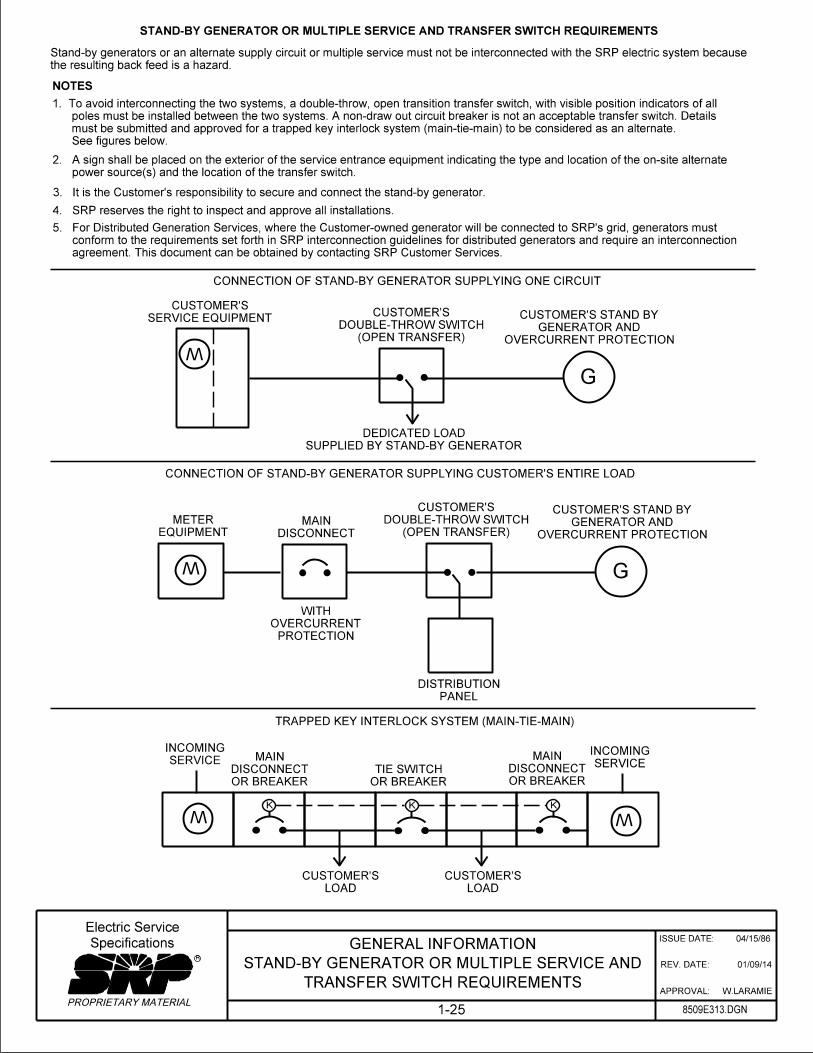
STAND-BY GENERATOR OR MULTIPLE SERVICE AND TRANSFER SWITCH REQUIREMENTS
the resulting back feed is a hazard.
Stand-by generators or an alternate supply circuit or multiple service must not be interconnected with the SRP electric system because
TRAPPED KEY INTERLOCK SYSTEM (MAIN-TIE-MAIN)
TRANSFER SWITCH REQUIREMENTS
STAND-BY GENERATOR OR MULTIPLE SERVICE AND
GENERAL INFORMATION04/15/86
01/09/14
W.LARAMIE
ISSUE DATE:
REV. DATE:
APPROVAL:
(OPEN TRANSFER)
DOUBLE-THROW SWITCH
CUSTOMER’S
OVERCURRENT PROTECTION
GENERATOR AND
CUSTOMER’S STAND BYSERVICE EQUIPMENT
CUSTOMER’S
CONNECTION OF STAND-BY GENERATOR SUPPLYING ONE CIRCUIT
SUPPLIED BY STAND-BY GENERATOR
DEDICATED LOAD
EQUIPMENT
METER
DISCONNECT
MAIN(OPEN TRANSFER)
DOUBLE-THROW SWITCH
CUSTOMER’S
OVERCURRENT PROTECTION
GENERATOR AND
CUSTOMER’S STAND BY
CONNECTION OF STAND-BY GENERATOR SUPPLYING CUSTOMER’S ENTIRE LOAD
PROTECTION
OVERCURRENT
WITH
PANEL
DISTRIBUTION
OR BREAKER
DISCONNECT
MAINSERVICE
INCOMING
SERVICE
INCOMING
OR BREAKER
DISCONNECT
MAIN
OR BREAKER
TIE SWITCH
LOAD
CUSTOMER’S
LOAD
CUSTOMER’S
Specifications
Electric Service
4. SRP reserves the right to inspect and approve all installations.
See figures below.
must be submitted and approved for a trapped key interlock system (main-tie-main) to be considered as an alternate.
poles must be installed between the two systems. A non-draw out circuit breaker is not an acceptable transfer switch. Details
1. To avoid interconnecting the two systems, a double-throw, open transition transfer switch, with visible position indicators of all
power source(s) and the location of the transfer switch.
2. A sign shall be placed on the exterior of the service entrance equipment indicating the type and location of the on-site alternate
3. It is the Customer’s responsibility to secure and connect the stand-by generator.
agreement. This document can be obtained by contacting SRP Customer Services.
conform to the requirements set forth in SRP interconnection guidelines for distributed generators and require an interconnection
5. For Distributed Generation Services, where the Customer-owned generator will be connected to SRP’s grid, generators must
NOTES

SUPPLY SIDE TAP
W
W
Main
W
W
Main
W
Mainor
Branch
W
LOAD SIDE TAP
4" Min.
Remote AC and DER Disconnect
Generator
1) Interconnected
Label Indicates:
Load Center
SES,
Note 10
Box
AC Combiner
Clearance
4" Min.
DER System
Customer’s
To
Pull Section
Billing Meter &
Center
Load
Protection Device
Overcurrent
Switch, Note
AC Disconnect
Utility
Notes
Note
Note
Meter, Note
System KWH
Dedicated DER
Item V
ESS 9-
Customer Device
PROPRIETARY MATERIAL8509E306.DGN1-26-1
ISSUE DATE:
REV. DATE:
APPROVAL:
05/06/09
S.DURAN
R
PAGE 1 OF 2
Specifications
Electric Service
Clearance
4, 8C & 12
8 & 9
9
7
8C & 12
16
REV: REVISED NOTE NUMBERS
04/27/18
RATED 300Kw OR LESS
DISTRIBUTED ENERGY RESOURCE INTERCONNECTION
GENERAL INFORMATION 30
Battery Storage
Customer
Meter & SES
To Customer BillingMeter
DER kWh
Dedicated
Charger
Battery
Inverter/
Notes 4, 8C & 12
AC Disconnect
Utility
Clearance
4" Min.
Notes 6, 8C & 12
Meter Disconnect
DER Storage
Notes 3, 8C & 12
kWh Meter
DER Storage
Clearance
4" Min.
Notes 3, 8C & 12
kWh Meter
DER Storage
Note 2
Load Panel
Customer Back-Up
Note 2
Load Panel
Customer Back-Up
PROPRIETARY MATERIAL
ISSUE DATE:
REV. DATE:
APPROVAL:
R
Specifications
Electric Service
04/27/18
S.DURAN
1-26-2
Notes 6, 8C & 12
Meter Disconnect
DER Storage
Notes 4, 8C & 12
AC Disconnect
Utility
W + -
W
W
+ -
+ -W
8509E357.DGN
OR LESS WITH STORAGE
INTERCONNECTION RATED 300kW
DISTRIBUTED ENERGY RESOURCE
GENERAL INFORMATION
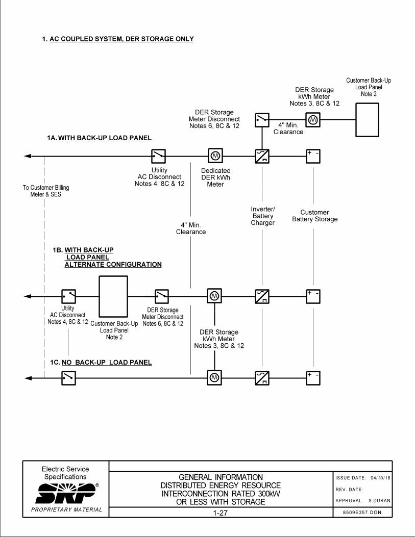
WITH BACK-UP LOAD PANEL1A.
AC COUPLED SYSTEM, DER STORAGE ONLY1.
ALTERNATE CONFIGURATION
LOAD PANEL
WITH BACK-UP1B.
NO BACK-UP LOAD PANEL1C.
30
1-27
Battery Charger
Inverter/
Battery Storage
Customer
System Inverter
PV
Dedicated
Meter & SES
To Customer Billing
Charger
Battery
Inverter/
Storage
Battery
Customer
12
Notes 4, 8C &
AC Disconnect
Utility
Clearance
4" Min.
12
Notes 3, 8C &
kWh Meter
DER Storage
Note 2
Panel
Back-Up Load
Customer
12
Notes 5, 8C &
Disconnect
DER Meter
CLEARANCE
4" MIN.
12
Notes 3, 8C &
kWh Meter
Dedicated DER
12
Notes 6, 8C &
Disconnect
Meter
DER Storage
12
Notes 3, 8C &
kWh Meter
DER Storage
Clearance
4" Min.
Note 3
System
To DER
PROPRIETARY MATERIAL
ISSUE DATE:
REV. DATE:
APPROVAL:
R
Specifications
Electric Service
04/27/18
S.DURAN
1-26-3
W W
W
+ -
+ -W
8509E358.DGN
OR LESS WITH STORAGE
INTERCONNECTION RATED 300kW
DISTRIBUTED ENERGY RESOURCE
GENERAL INFORMATION
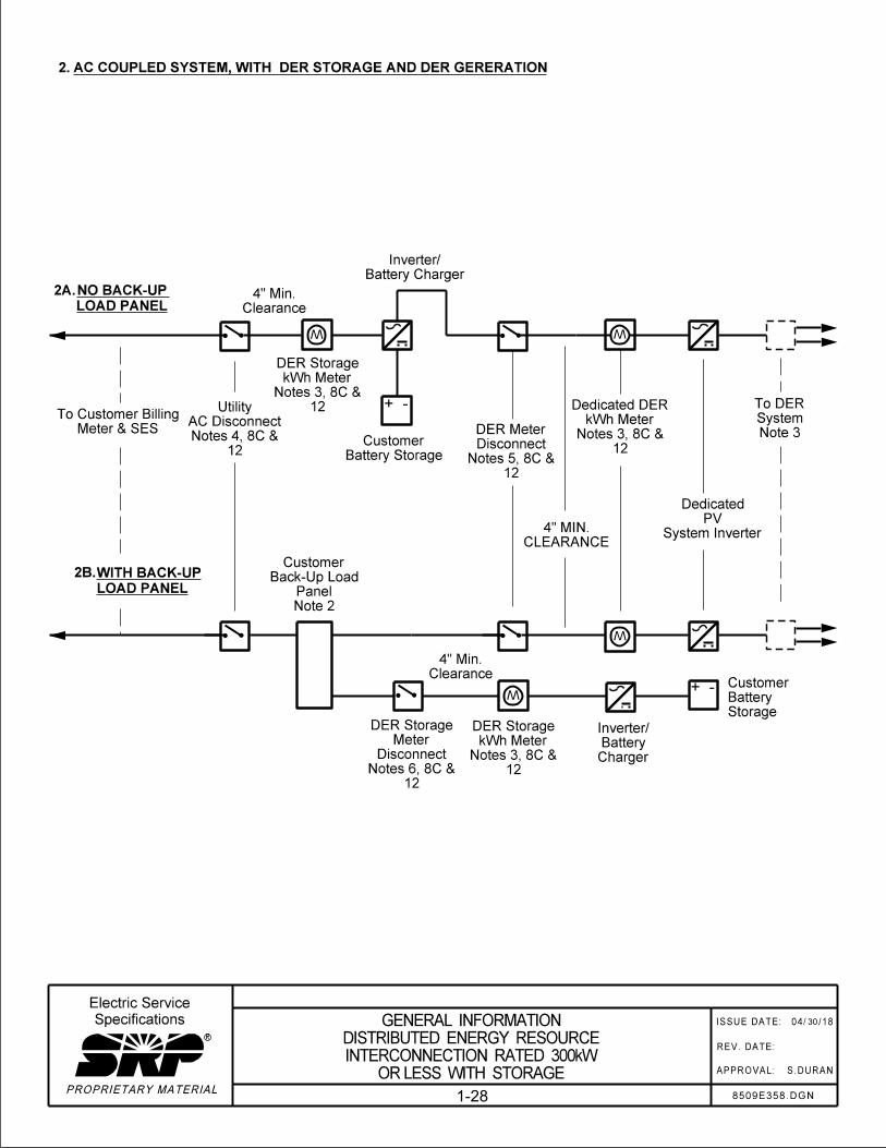
AC COUPLED SYSTEM, WITH DER STORAGE AND DER GERERATION2.
LOAD PANEL
NO BACK-UP 2A.
LOAD PANEL
WITH BACK-UP2B.
30
1-28
Battery Storage
Customer
Battery Charger
Inverter/
Battery Storage
Customer
12
Notes 4, 8C &
AC Disconnect
Utility
Clearance
4" Min.
Notes 3, 8C & 12
DER kWh Meter
Dedicated
Notes 6, 8C & 12
Meter Disconnect
DER Storage
Notes 3, 8C & 12
kWh Meter
DER Storage
Battery Charger
Inverter/
Clearance
4" Min.
Note 2
Panel
Back-Up Load
Customer
Panel Note 2
Back-Up Load
Customer
Battery Storage
Customer
Battery Charger
Inverter/
PROPRIETARY MATERIAL
ISSUE DATE:
REV. DATE:
APPROVAL:
R
Specifications
Electric Service
04/27/18
S.DURANOR LESS WITH STORAGE
INTERCONNECTION RATED 300kW
DISTRIBUTED ENERGY RESOURCE
GENERAL INFORMATION
1-26-4
Note 3
System
To DER
8C & 12
Notes 5,
Disconnect
DER Meter
& 12
Notes 4,8C
Disconnect
Utility AC
Meter & SES
To Customer Billing
W
+ -W
W
+ -
W
+ -
8509E359.DGN
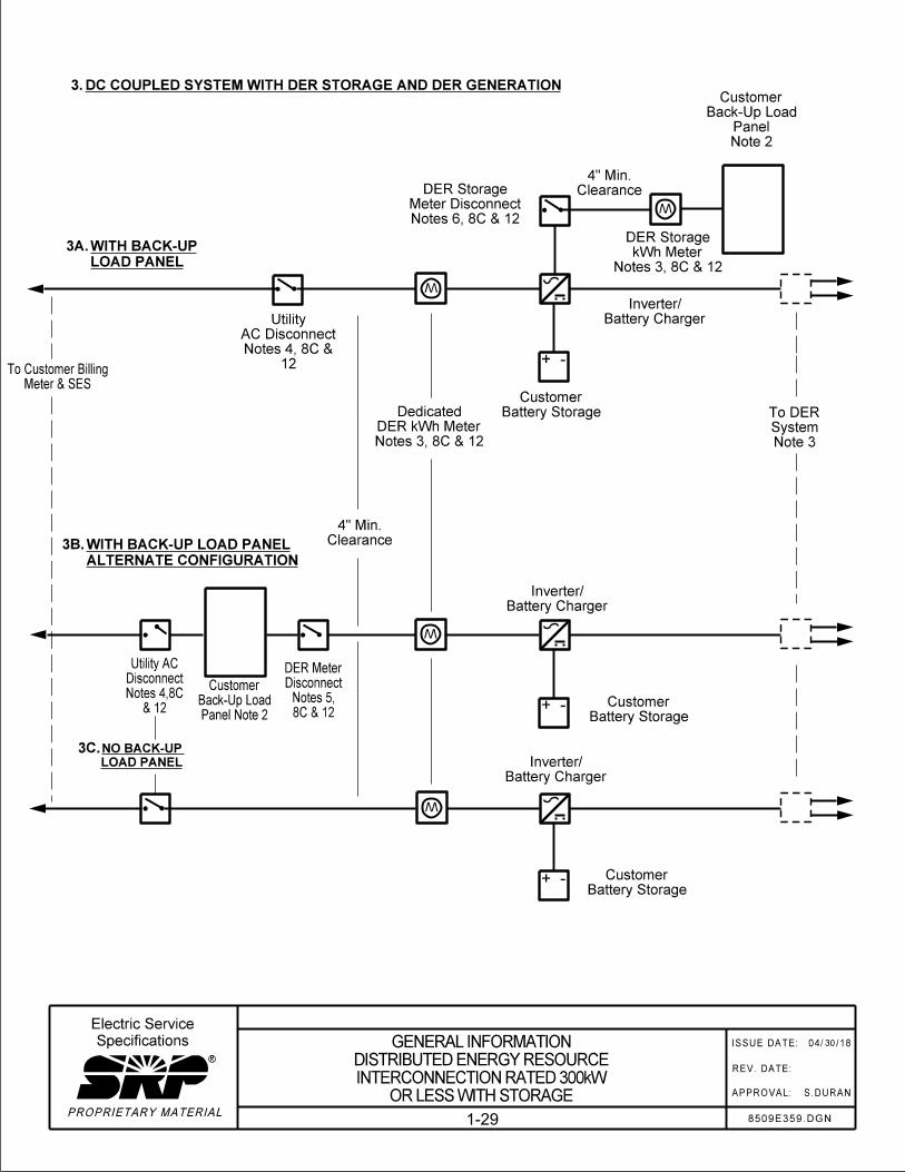
DC COUPLED SYSTEM WITH DER STORAGE AND DER GENERATION3.
LOAD PANEL
WITH BACK-UP3A.
ALTERNATE CONFIGURATION
WITH BACK-UP LOAD PANEL3B.
LOAD PANEL
NO BACK-UP 3C.
30
1-29
DISTRIBUTED ENERGY RESOURCE (DER) INTERCONNECTION RATED 300 kW OR LESS
Electric Service Specifications
PROPRIETARY MATERIAL
REV: Extensive revisions – added DER information Page 1 of 3
GENERAL INFORMATION DISTRIBUTED ENERGY RESOURCE
INTERCONNECTION RATED 300 kW OR LESS
ISSUE DATE: 05/08/09 REV. DATE: 04/30/18 APPROVAL: S. Duran
1-30 ESS1-30to1-32.doc
NOTES
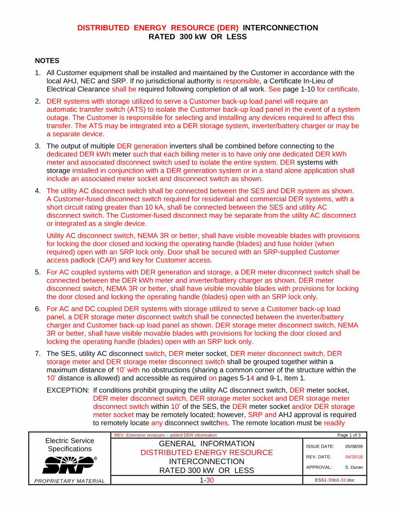
1. All Customer equipment shall be installed and maintained by the Customer in accordance with the local AHJ, NEC and SRP. If no jurisdictional authority is responsible, a Certificate In-Lieu of Electrical Clearance shall be required following completion of all work. See page 1-10 for certificate.
2. DER systems with storage utilized to serve a Customer back-up load panel will require an automatic transfer switch (ATS) to isolate the Customer back-up load panel in the event of a system outage. The Customer is responsible for selecting and installing any devices required to affect this transfer. The ATS may be integrated into a DER storage system, inverter/battery charger or may be a separate device.
3. The output of multiple DER generation inverters shall be combined before connecting to the dedicated DER kWh meter such that each billing meter is to have only one dedicated DER kWh meter and associated disconnect switch used to isolate the entire system. DER systems with storage installed in conjunction with a DER generation system or in a stand alone application shall include an associated meter socket and disconnect switch as shown.
4. The utility AC disconnect switch shall be connected between the SES and DER system as shown. A Customer-fused disconnect switch required for residential and commercial DER systems, with a short circuit rating greater than 10 kA, shall be connected between the SES and utility AC disconnect switch. The Customer-fused disconnect may be separate from the utility AC disconnect or integrated as a single device.
Utility AC disconnect switch, NEMA 3R or better, shall have visible moveable blades with provisions for locking the door closed and locking the operating handle (blades) and fuse holder (when required) open with an SRP lock only. Door shall be secured with an SRP-supplied Customer access padlock (CAP) and key for Customer access.
5. For AC coupled systems with DER generation and storage, a DER meter disconnect switch shall be connected between the DER kWh meter and inverter/battery charger as shown. DER meter disconnect switch, NEMA 3R or better, shall have visible movable blades with provisions for locking the door closed and locking the operating handle (blades) open with an SRP lock only.
6. For AC and DC coupled DER systems with storage utilized to serve a Customer back-up load panel, a DER storage meter disconnect switch shall be connected between the inverter/battery charger and Customer back-up load panel as shown. DER storage meter disconnect switch, NEMA 3R or better, shall have visible movable blades with provisions for locking the door closed and locking the operating handle (blades) open with an SRP lock only.
7. The SES, utility AC disconnect switch, DER meter socket, DER meter disconnect switch, DER storage meter and DER storage meter disconnect switch shall be grouped together within a maximum distance of 10’ with no obstructions (sharing a common corner of the structure within the 10’ distance is allowed) and accessible as required on pages 5-14 and 9-1, Item 1.
EXCEPTION: If conditions prohibit grouping the utility AC disconnect switch, DER meter socket, DER meter disconnect switch, DER storage meter socket and DER storage meter disconnect switch within 10’ of the SES, the DER meter socket and/or DER storage meter socket may be remotely located; however, SRP and AHJ approval is required to remotely locate any disconnect switches. The remote location must be readily
DISTRIBUTED ENERGY RESOURCE (DER) INTERCONNECTION RATED 300 kW OR LESS
Electric Service Specifications
PROPRIETARY MATERIAL
REV: Extensive revisions – added DER information Page 2 of 3
GENERAL INFORMATION DISTRIBUTED ENERGY RESOURCE
INTERCONNECTION RATED 300 kW OR LESS
ISSUE DATE: 05/08/09 REV. DATE: 04/30/18 APPROVAL: S. Duran
1-31 ESS1-30to1-32.doc
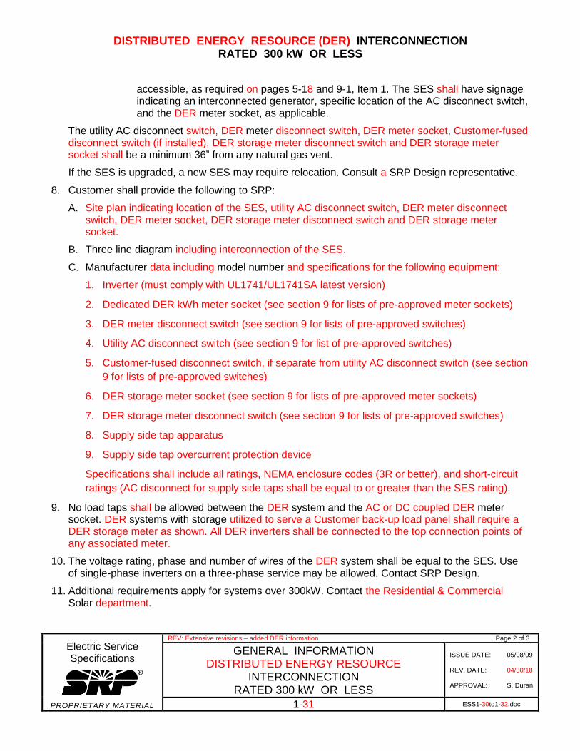
accessible, as required on pages 5-18 and 9-1, Item 1. The SES shall have signage indicating an interconnected generator, specific location of the AC disconnect switch, and the DER meter socket, as applicable.
The utility AC disconnect switch, DER meter disconnect switch, DER meter socket, Customer-fused disconnect switch (if installed), DER storage meter disconnect switch and DER storage meter socket shall be a minimum 36” from any natural gas vent.
If the SES is upgraded, a new SES may require relocation. Consult a SRP Design representative.
8. Customer shall provide the following to SRP:
A. Site plan indicating location of the SES, utility AC disconnect switch, DER meter disconnect switch, DER meter socket, DER storage meter disconnect switch and DER storage meter socket.
B. Three line diagram including interconnection of the SES.
C. Manufacturer data including model number and specifications for the following equipment:
1. Inverter (must comply with UL1741/UL1741SA latest version)
2. Dedicated DER kWh meter socket (see section 9 for lists of pre-approved meter sockets)
3. DER meter disconnect switch (see section 9 for lists of pre-approved switches)
4. Utility AC disconnect switch (see section 9 for list of pre-approved switches)
5. Customer-fused disconnect switch, if separate from utility AC disconnect switch (see section
9 for lists of pre-approved switches)
6. DER storage meter socket (see section 9 for lists of pre-approved meter sockets)
7. DER storage meter disconnect switch (see section 9 for lists of pre-approved switches)
8. Supply side tap apparatus
9. Supply side tap overcurrent protection device
Specifications shall include all ratings, NEMA enclosure codes (3R or better), and short-circuit
ratings (AC disconnect for supply side taps shall be equal to or greater than the SES rating).
9. No load taps shall be allowed between the DER system and the AC or DC coupled DER meter socket. DER systems with storage utilized to serve a Customer back-up load panel shall require a DER storage meter as shown. All DER inverters shall be connected to the top connection points of any associated meter.
10. The voltage rating, phase and number of wires of the DER system shall be equal to the SES. Use of single-phase inverters on a three-phase service may be allowed. Contact SRP Design.
11. Additional requirements apply for systems over 300kW. Contact the Residential & Commercial Solar department.
DISTRIBUTED ENERGY RESOURCE (DER) INTERCONNECTION RATED 300 kW OR LESS
Electric Service Specifications
PROPRIETARY MATERIAL
REV: Extensive revisions – added DER information Page 3 of 3
GENERAL INFORMATION DISTRIBUTED ENERGY RESOURCE
INTERCONNECTION RATED 300 kW OR LESS
ISSUE DATE: 05/08/09 REV. DATE: 04/30/18 APPROVAL: S. Duran
1-32 ESS1-30to1-32.doc
12. Labeling requirements per Section 11 – Contractor-Supplied Material, Distributed Energy Resource Signage.
FAULT CURRENT TABLES
Electric Service Specifications
PROPRIETARY MATERIAL
REV: Clarified 400 AMP residential panel as 320 class.
GENERAL INFORMATION
FAULT CURRENT TABLES
ISSUE DATE: 04/15/86
REV. DATE: 08/30/17
APPROVAL: N. Sabbah
1-33 ESS1-33to1-36.doc
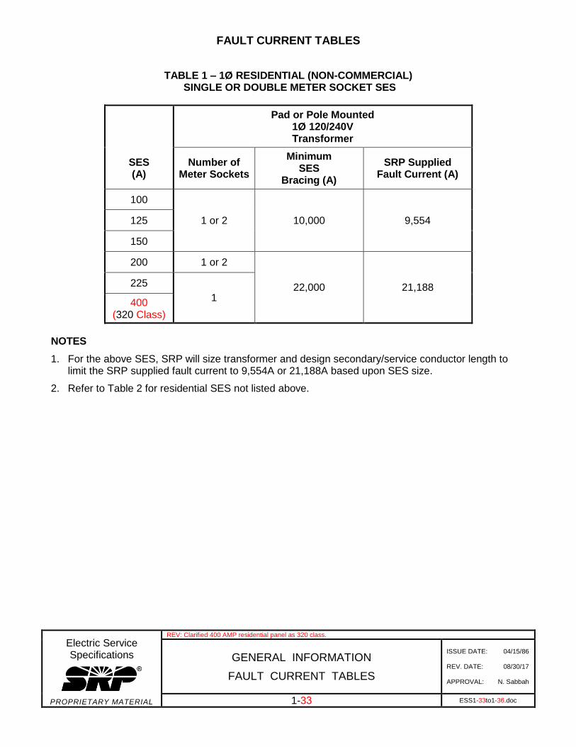
TABLE 1 – 1Ø RESIDENTIAL (NON-COMMERCIAL) SINGLE OR DOUBLE METER SOCKET SES
Pad or Pole Mounted 1Ø 120/240V Transformer
SES (A)
Number of Meter Sockets
Minimum SES
Bracing (A)
SRP Supplied Fault Current (A)
100
1 or 2 10,000 9,554 125
150
200 1 or 2
22,000 21,188 225
1 400 (320 Class)
NOTES
1. For the above SES, SRP will size transformer and design secondary/service conductor length tolimit the SRP supplied fault current to 9,554A or 21,188A based upon SES size.
2. Refer to Table 2 for residential SES not listed above.
FAULT CURRENT TABLES
Electric Service Specifications
PROPRIETARY MATERIAL
REV: Clarified 400 AMP residential panel as 320 class.
GENERAL INFORMATION
FAULT CURRENT TABLES
ISSUE DATE: 04/15/86
REV. DATE: 08/30/17
APPROVAL: N. Sabbah
1-34 ESS1-33to1-36.doc
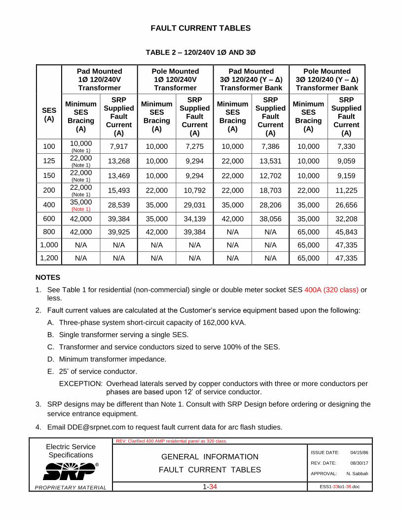
TABLE 2 – 120/240V 1Ø AND 3Ø
SES (A)
Pad Mounted 1Ø 120/240V Transformer
Pole Mounted 1Ø 120/240V Transformer
Pad Mounted 3Ø 120/240 (Y – Δ) Transformer Bank
Pole Mounted 3Ø 120/240 (Y – Δ) Transformer Bank
Minimum SES
Bracing (A)
SRP Supplied
Fault Current
(A)
Minimum SES
Bracing (A)
SRP Supplied
Fault Current
(A)
Minimum SES
Bracing (A)
SRP Supplied
Fault Current
(A)
Minimum SES
Bracing (A)
SRP Supplied
Fault Current
(A)
100 10,000 (Note 1)
7,917 10,000 7,275 10,000 7,386 10,000 7,330
125 22,000 (Note 1)
13,268 10,000 9,294 22,000 13,531 10,000 9,059
150 22,000 (Note 1)
13,469 10,000 9,294 22,000 12,702 10,000 9,159
200 22,000 (Note 1)
15,493 22,000 10,792 22,000 18,703 22,000 11,225
400 35,000 (Note 1)
28,539 35,000 29,031 35,000 28,206 35,000 26,656
600 42,000 39,384 35,000 34,139 42,000 38,056 35,000 32,208
800 42,000 39,925 42,000 39,384 N/A N/A 65,000 45,843
1,000 N/A N/A N/A N/A N/A N/A 65,000 47,335
1,200 N/A N/A N/A N/A N/A N/A 65,000 47,335
NOTES
1. See Table 1 for residential (non-commercial) single or double meter socket SES 400A (320 class) orless.
2. Fault current values are calculated at the Customer’s service equipment based upon the following:
A. Three-phase system short-circuit capacity of 162,000 kVA.
B. Single transformer serving a single SES.
C. Transformer and service conductors sized to serve 100% of the SES.
D. Minimum transformer impedance.
E. 25’ of service conductor.
EXCEPTION: Overhead laterals served by copper conductors with three or more conductors per phases are based upon 12’ of service conductor.
3. SRP designs may be different than Note 1. Consult with SRP Design before ordering or designing the
service entrance equipment.
4. Email [email protected] to request fault current data for arc flash studies.
FAULT CURRENT TABLES
Electric Service Specifications
PROPRIETARY MATERIAL
GENERAL INFORMATION
FAULT CURRENT TABLES
ISSUE DATE: 04/15/86
REV. DATE: 02/28/17
APPROVAL: N. Sabbah
1-35 ESS1-33to1-36.doc
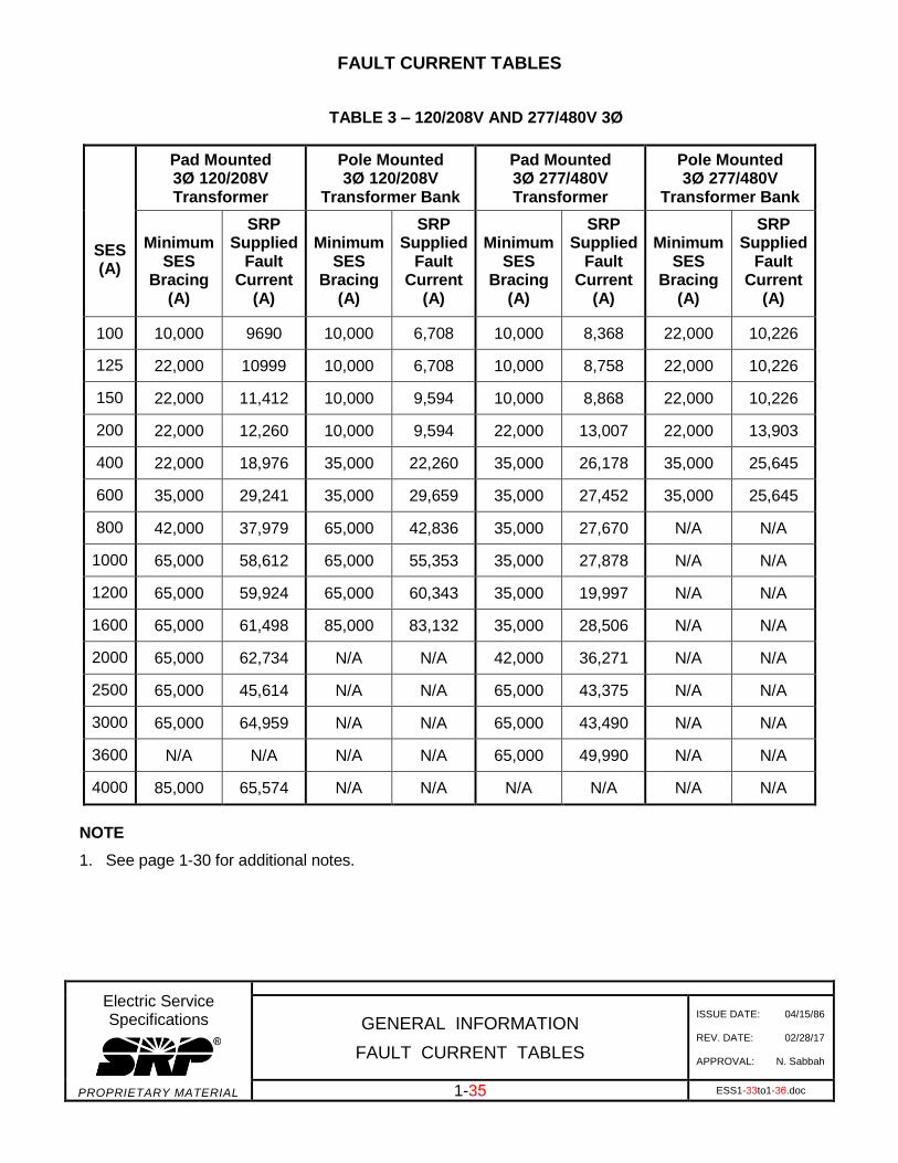
TABLE 3 – 120/208V AND 277/480V 3Ø
SES (A)
Pad Mounted 3Ø 120/208V Transformer
Pole Mounted 3Ø 120/208V
Transformer Bank
Pad Mounted 3Ø 277/480V Transformer
Pole Mounted 3Ø 277/480V
Transformer Bank
Minimum SES
Bracing (A)
SRP Supplied
Fault Current
(A)
Minimum SES
Bracing (A)
SRP Supplied
Fault Current
(A)
Minimum SES
Bracing (A)
SRP Supplied
Fault Current
(A)
Minimum SES
Bracing (A)
SRP Supplied
Fault Current
(A)
100 10,000 9690 10,000 6,708 10,000 8,368 22,000 10,226
125 22,000 10999 10,000 6,708 10,000 8,758 22,000 10,226
150 22,000 11,412 10,000 9,594 10,000 8,868 22,000 10,226
200 22,000 12,260 10,000 9,594 22,000 13,007 22,000 13,903
400 22,000 18,976 35,000 22,260 35,000 26,178 35,000 25,645
600 35,000 29,241 35,000 29,659 35,000 27,452 35,000 25,645
800 42,000 37,979 65,000 42,836 35,000 27,670 N/A N/A
1000 65,000 58,612 65,000 55,353 35,000 27,878 N/A N/A
1200 65,000 59,924 65,000 60,343 35,000 19,997 N/A N/A
1600 65,000 61,498 85,000 83,132 35,000 28,506 N/A N/A
2000 65,000 62,734 N/A N/A 42,000 36,271 N/A N/A
2500 65,000 45,614 N/A N/A 65,000 43,375 N/A N/A
3000 65,000 64,959 N/A N/A 65,000 43,490 N/A N/A
3600 N/A N/A N/A N/A 65,000 49,990 N/A N/A
4000 85,000 65,574 N/A N/A N/A N/A N/A N/A
NOTE
1. See page 1-30 for additional notes.
FAULT CURRENT TABLES
Electric Service Specifications
PROPRIETARY MATERIAL
GENERAL INFORMATION
FAULT CURRENT TABLES
ISSUE DATE: 04/15/86
REV. DATE: 02/28/17
APPROVAL: N. Sabbah
1-36 ESS1-33to1-36.doc
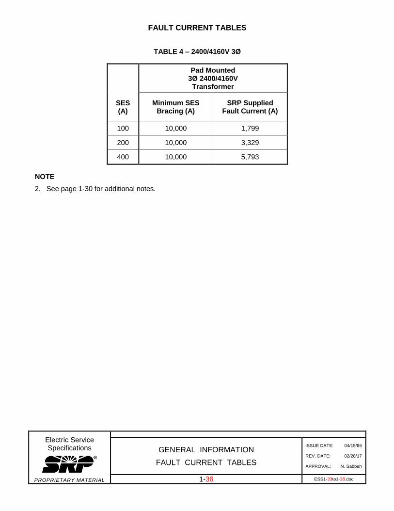
TABLE 4 – 2400/4160V 3Ø
SES (A)
Pad Mounted 3Ø 2400/4160V Transformer
Minimum SES Bracing (A)
SRP Supplied Fault Current (A)
100 10,000 1,799
200 10,000 3,329
400 10,000 5,793
NOTE
2. See page 1-30 for additional notes.
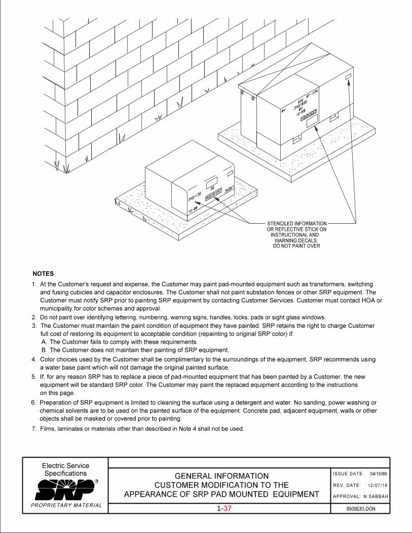
INSTRUCTIONAL AND
DO NOT PAINT OVER
STENCILED INFORMATION
8509E83.DGN
04/15/89
OR REFLECTIVE STICK ON
WARNING DECALS;
PROPRIETARY MATERIAL
ISSUE DATE:
R
Specifications
Electric Service
1-33
NOTES
a water base paint which will not damage the original painted surface.
4. Color choices used by the Customer shall be complimentary to the surroundings of the equipment. SRP recommends using
7. Films, laminates or materials other than described in Note 4 shall not be used.
B. The Customer does not maintain their painting of SRP equipment.
A. The Customer fails to comply with these requirements.
full cost of restoring its equipment to acceptable condition (repainting to original SRP color) if:
3. The Customer must maintain the paint condition of equipment they have painted. SRP retains the right to charge Customer
municipality for color schemes and approval.
Customer must notify SRP prior to painting SRP equipment by contacting Customer Services. Customer must contact HOA or
and fusing cubicles and capacitor enclosures. The Customer shall not paint substation fences or other SRP equipment. The
1. At the Customer’s request and expense, the Customer may paint pad-mounted equipment such as transformers, switching
on this page.
equipment will be standard SRP color. The Customer may paint the replaced equipment according to the instructions
5. If, for any reason SRP has to replace a piece of pad-mounted equipment that has been painted by a Customer, the new
12/07/16
N.SABBAH
REV. DATE:
APPROVAL:
objects shall be masked or covered prior to painting.
chemical solvents are to be used on the painted surface of the equipment. Concrete pad, adjacent equipment, walls or other
6. Preparation of SRP equipment is limited to cleaning the surface using a detergent and water. No sanding, power washing or
240/
120
50
3508
7
10-8
8
500
240/
800
WH
10-8
8WH
PD2
22
2
22
2
2D
P
87-1
330
2. Do not paint over identifying lettering, numbering, warning signs, handles, locks, pads or sight glass windows.
APPEARANCE OF SRP PAD MOUNTED EQUIPMENT
CUSTOMER MODIFICATION TO THE
GENERAL INFORMATION
1-37