SEBD0350, English Performance Handbook, Edition 40, …€¦ · throughs setting the new standard...
24
Edition 40 2-1 CONTENTS Industries Served . . . . . . . . . . . . . . . . . . . . . . . .2-1 Features . . . . . . . . . . . . . . . . . . . . . . . . . . . . . . .2-2 Applications . . . . . . . . . . . . . . . . . . . . . . . . . . . .2-7 Specifications: Standard Versions . . . . . . . . . .2-10 Specifications: Global Versions . . . . . . . . . . . .2-12 Travel Speeds . . . . . . . . . . . . . . . . . . . . . . . . . .2-15 All Wheel Drive (AWD) . . . . . . . . . . . . . . . . . . .2-16 Mid Mount and Front Mount Scarifiers . . . . .2-16 Rear Ripper and Rear Ripper/Scarifier . . . . . .2-17 Production . . . . . . . . . . . . . . . . . . . . . . . . . . . . .2-18 Formulas . . . . . . . . . . . . . . . . . . . . . . . . . . . . . .2-22 Extreme Slope Operation . . . . . . . . . . . . . . . . .2-23 Work Tools . . . . . . . . . . . . . . . . . . . . . . . . . . . . .2-24 INDUSTRIES SERVED The motor grader is one of the most versatile work tools in the Cat ® product line. The M-Series machines are used in numerous applications within a wide range of industries. The major industries using Cat motor graders, along with the typical applications within each, are summarized below. ● Heavy Construction Highway Construction Paving/Resurfacing Airport Construction Railroad Construction Dam and Levee Construction Haul Road Maintenance ● Governmental Road Maintenance Road Construction Ditch Building/Cleaning Snow Removal ● Building Construction Residential Construction Commercial Construction Industrial Construction Sewer and Water Systems ● Industrial Waste Disposal Pipeline Construction ● Mining Haul Road Maintenance Snow Removal ● Forestry Access Road Construction Forest Development Snow Removal Haul Road Maintenance ● Geographic Versions — Cat Motor Graders were specifically designed to meet the needs of different geographic regions and regulations. K-Series Versions for less regulated locations and M Series Global Versions are available with an assortment of standard features and optional equipment. All motor graders feature advanced electronically controlled Cat engines, power train components, hydraulics and machine structures. 2 MOTOR GRADERS
Transcript of SEBD0350, English Performance Handbook, Edition 40, …€¦ · throughs setting the new standard...
Edition 40 2-1
CONTENTSIndustries Served . . . . . . . . . . . . . . . . . . . . . . . .2-1Features . . . . . . . . . . . . . . . . . . . . . . . . . . . . . . .2-2Applications . . . . . . . . . . . . . . . . . . . . . . . . . . . .2-7Specifications: Standard Versions . . . . . . . . . .2-10Specifications: Global Versions . . . . . . . . . . . .2-12Travel Speeds . . . . . . . . . . . . . . . . . . . . . . . . . .2-15All Wheel Drive (AWD) . . . . . . . . . . . . . . . . . . .2-16Mid Mount and Front Mount Scarifiers . . . . .2-16Rear Ripper and Rear Ripper/Scarifier . . . . . .2-17Production . . . . . . . . . . . . . . . . . . . . . . . . . . . . .2-18Formulas . . . . . . . . . . . . . . . . . . . . . . . . . . . . . .2-22Extreme Slope Operation . . . . . . . . . . . . . . . . .2-23Work Tools . . . . . . . . . . . . . . . . . . . . . . . . . . . . .2-24
INDUSTRIES SERVEDThe motor grader is one of the most versatile work
tools in the Cat® product line. The M-Series machinesare used in numerous applications within a wide rangeof industries. The major industries using Cat motorgraders, along with the typical applications withineach, are summarized below.
● Heavy ConstructionHighway ConstructionPaving/ResurfacingAirport ConstructionRailroad ConstructionDam and Levee ConstructionHaul Road Maintenance
● GovernmentalRoad MaintenanceRoad ConstructionDitch Building/CleaningSnow Removal
● Building ConstructionResidential ConstructionCommercial ConstructionIndustrial ConstructionSewer and Water Systems
● IndustrialWaste DisposalPipeline Construction
● MiningHaul Road MaintenanceSnow Removal
● ForestryAccess Road ConstructionForest DevelopmentSnow RemovalHaul Road Maintenance
● Geographic Versions — Cat Motor Graders werespecifically designed to meet the needs of dif ferentgeographic regions and regulations. K-SeriesVersions for less regulated locations and M SeriesGlobal Versions are available with an assortmentof standard features and optional equip ment. Allmotor graders feature advanced electron icallycon trolled Cat engines, power train components,hydraulics and machine structures.
2
MOTOR GRADERS
FEATURES, M-Series Motor Graders:Building on the strong heritage of the H-Series,
the M-Series delivers multiple technological break-throughs setting the new standard for motor graders.The H-Series has been the industry standard in avariety of heavy construction, mining, road build-ing and governmental applications. The M-Seriescontinues this tradition, incorporating revolution-ary, customer-driven enhancements by:
– Improving ease of operation and operation train -ing time
– Best-in-class operator station and unmatchedvisibility
– Maximum productivity– Improving availability and decreasing mainte-
nance time
The M-Series line includes seven models: 120M/120M AWD, 12M, 140M/140M AWD, 160M/160MAWD, 14M, 16M, 24M. The 120M through 14M meetconstruction, road building, and governmental appli -cations. Three of the models introduce All WheelDrive (AWD) as an option. AWD improves tractionin poor underfoot conditions such as snow, mud, andsand. The 16M and 24M meet the specialized needsof large mining customers.
● Operation Station: The 120M through 16M mod-els feature a revolutionary cab design that pro-vides unmatched comfort, visibility and ease of use,making the operator more confident and produc-tive. The M-Series provides a comfortable envi-ronment to keep the operator alert and focused.The interior noise level is maintained between 70and 74 dB(A) with the doors and windows closed.
Ease of Operation. The revolutionary joystickcontrols and exceptional visibility make the M-Serieseasier to operate without sacrificing control. Theintuitive joystick control pattern allows both newand experienced operators to become productivequickly. Logical grouping of hydraulic functionsin the joysticks allow any operator to easily con-trol several functions at the same time. This allowsthe operator to be more productive and remaincomfortable throughout the work shift.
Advanced Joystick Controls. Two electro-hydraulic joysticks reduce hand and wrist move-ment as much as 78% compared to conventionallever controls for greatly enhanced operator effi-ciency. The intuitive pattern is easy to learn andprovides the precise implement control to allowboth new and experienced operators to becomeproductive quickly. Logical grouping of hydraulicfunctions in the joysticks allow any operator tocontrol several functions at the same time formore productivity.
Visibility. The 120M through 16M models boastexcellent visibility to the work area, made possiblewith angled cab doors, a tapered engine enclosureand a patented sloped rear window. Ample glassarea and carefully placed components provideexcellent visibility to enhance operator confidenceand productivity in all motor grader applications.The M-Series gives the operator an exceptionalview forward to the blade, working surface andfront tires. The M-Series black glare-reducing painton the front frame and engine enclosure enhancesvisibility.
Comfort and Convenience. Caterpillar has builtthe most comfortable cab in the industry by replac -ing the control levers and steering wheel with twojoystick controls, and using a deeper cab designto give more leg room.
2-2 Edition 40
Motor Graders Features
● Drawbar, Circle and Moldboard: The 120Mthrough 16M models provide a broad range ofextended blade positions particularly beneficialin mid-range bank sloping, ditch cutting and ditchcleaning. A long wheel base allows for an aggres-sive blade angle permitting material to roll morefreely, reducing power requirements. Top-acces-sible drawbar wear inserts and the shimless mold -board retention system make DCM adjustmentsfast and simple, delivering more precise materialcontrol while lowering operating costs.
Top-Adjust Drawbar Wear Strips. The patentedtop-adjust wear strips dramatically reduce draw-bar/circle adjustment time. By removing the accessplates on top of the drawbar, shims and wearstrips can easily be added or replaced. This fea-ture reduces service downtime and lowers over-all machine operating costs.
Shimless Moldboard Retention System. Theunique shimless moldboard retention systemreduces the potential for blade chatter. Adjustingscrews keep the moldboard’s wear strips alignedfor precise blade control and dramatic reductionsin service time.
● Power Train: Integrated, electronically controlledsystems, deliver smooth reliable performancewith reduced operating costs.
Smooth Shifting Transmission. The M-Seriescombine several key innovations to ensure smooth,powerful shifts throughout the gear range.
Electronically Controlled Shifting. The fullElec tronic Clutch Pressure Control (ECPC) sys-tem optimizes inching modulation and smoothesshifting between all gears and directional changes.This provides outstanding control and also extendsthe life of the transmission by reducing stress ongears.
Load Compensation. This standard featureensures consistent shift quality regardless ofblade or machine load.
Hydraulic Brakes. The oil bathed, multi-disc ser -vice brakes are hydraulically actuated, providingsmooth predictable braking and lower operatingcosts. With brakes located at each tandem wheel,the M-Series offer the largest total brake surfacearea in the industry, delivering dependable stop-ping power and longer brake life.
Edition 40 2-3
2
Motor GradersFeatures
● Engine: The M-Series combine power manage-ment with ACERT™ Technology to deliver maxi-mum power and efficiency while reducing theenvironmental impact.
ACERT™ Technology. ACERT Technology allowsCat engines to supply more power per unit of dis-placement without causing premature wear. Thisbreakthrough technology reduces emissions dur-ing the combustion process by using advancedtechnology in the air and fuel systems, in conjunc -tion with integrated electronics. ACERT Tech -nology enhances overall engine performance whiledramatically reducing exhaust emissions.
Power Management. The M-Series Power Man -agement System automatically delivers an addi-tional 3.7 kW (5 hp) in each forward gear 1stthrough 4th, and each reverse gear 1st through 3rd.This standard feature optimizes rimpull for allgears by balancing traction, speed and horsepowerwhile conserving fuel. The system limits horse-power in lower gears, which helps reduce wheelslip where traction is limited. With the VariableHorsepower Plus (VHP Plus) option, an additional3.7 kW (5 hp) is delivered in each forward gear5th through 8th for more power at higher speeds.
Exhaust Emissions Compliant. The Cat ACERTTechnology engines meet or exceed all U.S. EPATier 3 and European Union Stage IIIa emissionscontrol standards.
● Hydraulics: The M-Series electro-hydraulicsenable advanced machine controls with preciseand predictable movements.
Advanced Electro-Hydraulic System. TheM-Series incorporates a state-of-the-art electro-hydraulic system. This technology is the founda-tion for revolutionary changes of the machine andimplement controls. Advanced joystick controlsprovide unmatched controllability with preciseand predictable hydraulic movements, and thereliability you expect from Caterpillar.
Load Sensing Hydraulics (PPPC). The timeproven load-sensing system and the advancedProportional Priority Pressure-Compensating(PPPC, or “triple-PC”) electro-hydraulic valves onthe M-Series are designed to provide superiorimplement control and enhanced machine per-formance in all applications. Continuous match-ing of hydraulic flow and pressure to power demandscreates less heat and reduces power consumption.
● Integrated Electronic Solutions: Full systemsintegration optimizes machine performance andavailability.
“Smart Machine.” The M-Series fully integrateall core systems creating a “Smart Machine.” TheCat data link shares key data among systems,optimizing machine performance while prevent-ing potential machine damage.
AccuGrade™ Attachment Ready Option. TheAccuGrade Attachment Ready Option is fullyintegrated into the machine design, makinginstallation quick and easy. Integral hydraulic andelectrical components are standard on M-Series(Grade Control Ready). The AccuGrade Attach -ment Ready Option provides additional mount-ing brackets, cab controls and electrical harnessesfor easy installation of the Cross Slope, Sonic,Laser, GPS or ATS electronics kits.
2-4 Edition 40
Motor Graders Features
● Serviceability:
Grouped Service Points. The M-Series groupdaily service points in the left side service centerto help ensure proper maintenance and inspec-tion routines.
Extended Service Intervals. The M-Seriesextended service intervals, such as 500-hourengine oil changes and 4000-hour hydraulic oilchanges, reduce machine service time and increaseavailability.
Ecology Drains. Conveniently located ecologydrains shorten service times and help keep theenvironment safe by preventing spills.
Diagnostics and Monitoring. The M-Seriespro vides Cat Messenger as standard equipment toenhance diagnostic capabilities by displayingmachine system errors and fault codes. Cat Elec -tronic Technician is a two way communication toolthat provides easy access to stored diagnostic dataand lets technicians configure machine parame-ters through the Cat Data Link. The optional ProductLink provides a communication flow of vital machinedata and location. The M-Series integrates CatMessenger, Cat Electronic Technician, and S·O·SSM
analysis for easy monitoring and fast trouble shoot-ing, keeping your machine up and running.
● Safety. Safety is an integral part of all machineand system designs. The M-Series machines pro-vide a safe working environment for both theoperator and ground personnel. ROPS and FOPSstructures meeting current SAE and ISO require-ments are standard on all Global machines. Back-up alarms are also standard on the M Series.
Operator Presence System. The Operator Pre -sence System keeps the parking brake engageduntil the operator is seated for safe operation.
Secondary Steering System. The standard sec-ondary steering system automatically engages incase of a drop in steering pressure, allowing theoperator to steer the machine to a stop.
Speed Sensitive Steering. The steering soft-ware automatically provides an infinitely vari-able ratio between the joystick and the steer tires,resulting in less sensitive steering as the ground-speed increases.
Hydraulic Lockout. A simple switch located inthe cab disables all implement functions whilestill providing machine steering control. Thissafety feature is especially useful while themachine is roading.
Circle Drive Slip Clutch. This standard featureprotects the drawbar, circle and moldboard fromshock loads when the end of the blade encountersimmovable objects. It also reduces the possibilityof abrupt directional changes in poor traction conditions, protecting the machine, operator and surroundings.
Blade Lift Accumulators. This optional featureuses accumulators to help absorb impact loads tothe moldboard by allowing vertical blade travel.Blade lift accumulators reduce unnecessary wearand help to avoid unintended machine movementfor increased operator safety.
Drop-Down Rear Lights. Optional drop downlights fold out from the rear of the machine. Thiscreates a wider, lower profile, to be better alignedwith passenger cars.
Rear View Camera. Visibility is further enhancedwith an optional Work Area Vision System (WAVS)LCD color monitor in the cab.
● Best Product Support: Cat motor grader usersare assured the best product support anywherein the world. With industry-best parts avail abil -ity, training and an offering of inspection, main-te nance and repair, Cat dealers can provide thesupport needed to keep the machines productive.
Edition 40 2-5
2
Motor GradersFeatures
FEATURES, K-Series Motor Graders:
OverviewThe K-Series model line-up is targeted to meet
customer requirements in less regulated countries.Built on the success of the Standard H-Series, theK-Series delivers multiple improvements in emis-sions control and operator features, while still main-taining the industry standard for reliability. TheK-Series model line-up consists of the 120K, 12K,140K and 160K.
Engine● ACERT Engine Technology: The K-Series mod-
els are equipped with Caterpillar ACERT enginetechnology, which uses numerous advanced com-ponents to efficiently produce more power and feweremissions.
● Emissions Compliant: The K-Series machinesmeet or exceed US EPA Tier 2 and EU Stage IIemissions regulations.
● Power Management Strategy: The K-Seriespower management strategy provides an addi-tional 7.5 kW (10 hp) increase in third and another7.5 kW (10 hp) in fourth gear through VariableHorsepower (VHP). This allows the operator tomain tain maximum rimpull while increasingground speed and productivity.
Power Train● Electronic Clutch Pressure Control (ECPC):
This standard K-Series feature smoothes shiftsand improves inching control. The system usesinput from the transmission and operator controlsto modulate the directional clutches and produceconsistent shifting.
● Autoshift: This optional feature improves easeof operation and maximizes productivity by auto-matically shifting the transmission at optimalshifting points.
Serviceability● Grouped Service Points: The K-Series group
daily service points in the left side service centerto help ensure proper maintenance and inspec-tion routines.
● Diagnostic Capability: The K-Series offer animproved dash cluster to keep the operator informedof critical system conditions. Cat Electronic Techni -cian is also offered and this allows faster diag-nostic capabilities by service personnel. ProductLink allows tracking of vital machine data andlocation providing a convenient way to track themachine.
● Extended Service Intervals: Improvements inserviceability allow increased machine operationbetween service intervals. The machines can oper-ate a full 500 hours between engine oil and filterchanges, 4,000 hours between hydraulic oil changes,and 12,000 hours between engine coolant changes.This reduces downtime and operating expense.
2-6 Edition 40
Motor Graders Features
APPLICATIONS, Motor Graders:The broad line of Cat motor graders allows the
customer to choose a motor grader that best fits theintended application. Below is a summary of thetypical motor grader applications.
Finish GradingThis application involves preparing a roadway or
site surface for future paving or other constructionactivity. The material being moved is usually a hard,dry base material on a solid underfoot. Finish blad-ing is the motor grader application that requires thehighest degree of accuracy. Thus, it is primarily doneat low operating speeds — usually less than 5 km/h(3 mph) — in gears 1 and 2. To ensure a smooth,even finished surface, one gear is usually maintainedfor a given pass. Pass lengths during this applica-tion are usually less than 600 m (2000 feet) for roadconstruction and 150 m (500 feet) for site develop-ment. Most finish blading is performed by contractorsin the Heavy Construction and Building Con struc -tion industries.
Heavy BladingThis application involves cutting, moving, and
mixing material, usually in the initial stages of sur-face preparation. A variety of material types aremoved in this manner, and the blade tip positionvaries accordingly. Full blade loads are usually expe-rienced during heavy blading, since moving mater-ial is the primary goal. Pass lengths within thisapplication vary, but are usually less than 600 m(2000 feet). Unlike with finish blading, the speed ofthe machine is dependent on the load being movedwhen heavy blading material. Typical operatingspeeds are from 0-10 km/h (0 to 6 mph). Therefore,gears 2 through 4 are frequently used in this appli-cation. Most heavy blading activity is performed bycontractors in the Heavy Construction, Govern -mental, Industrial, and Forestry industries.
Site PreparationThis application involves any material cutting,
moving, and mixing necessary to prepare a resi-dential, commercial, or industrial site for construc-tion. A variety of materials are encountered in thisapplication. Blade loads vary depending on theactivity being performed. Both heavy blading andfinish blading are performed when preparing a site.Pass lengths are typically in the range of 30-300 m(100 to 1000 feet). Typical operating speeds for sitepreparation vary depending on whether heavy blad-ing or finish blading activities are being performed.Most site preparation activities are performed bycontractors in the Building Construction industry.
Road MaintenanceThis application involves reshaping dirt or gravel
roads to maintain a crown or superelevation, or restor -ing the surface itself. This generally involves sec-ondary roads maintained by governmental bodies suchas townships and counties. Materials being movedin this application vary from extremely hard dirtbases to moist gravel surfaces. The typical blade loadfalls between that of finish blading and heavy blad -ing. Pass lengths are frequently longer than 600 m(2000 feet), and can extend for miles. The general speedrange for this application is 5-16 km/h (3 to 10 mph),corresponding to gears 2 (heavy dirt) through 5 (softgravel). As with finish blading, accuracy of the gradedsurface is the primary concern in this application.Thus, frequent shifts should be avoided wheneverpossible. A gear should be chosen and main tainedunless there is a significant change in the materialbeing moved. Most road maintenance activ ities areperformed by the Governmental industry.
Edition 40 2-7
2
Motor GradersApplications
Haul Road MaintenanceThis application of the motor grader involves
reshaping haul roads at mining, construction, orforestry work sites, usually for the purpose of main-taining smooth travel surfaces for equipment.Materials being moved while maintaining haulroads vary widely depending on the application.Typical blade loads are about one-third to half offull capacity. Some haul roads that experience largehauling units travelling on soft material may requireheavy blade loads in order to reshape the road sur-face. Pass lengths vary depending on the applica-tion, but can extend for miles on remote forestry orlarge mine haul roads. The general speed range forhaul road maintenance is heavily dependent on thematerial being moved as well as the grade of thehaul road. Many mine sites are in mountainous areas,requiring haul roads with steep grades. Generally,haulroad maintenance is performed at speeds sim-ilar to those required for general road maintenance5-16 km/h (3 to 10 mph).
A travel surface that allows for the safe and effi-cient movement of machinery is the ultimate goalwith this motor grader application. Very precise road -way elevations and slopes are desired, but are notas crucial as they are when finish blading. Most haulroad maintenance activities are performed by theMining, Heavy Construction, and Forestry industries.
Side/Bank Slope WorkThis application involves preparing side slopes or
bank slopes along roadways by placing the mold-board on a sloped surface. Slopes of up to a 2:1 anglecan be cut using a motor grader. Often the motorgrader is operated on the level surface adjacent tothe slope, and the moldboard is extended outward tothe sloped surface. Fine soils are generally encoun-tered in this application of the motor grader. Bladeloads are usually less than half of the full-bladecapacity, and pass lengths are seldom longer than600 m (2000 feet). A smooth-graded sloped surfaceis the primary concern in this application, so fre-quent shifts should be avoided. The typical speedrange is 0-6 km/h (0 to 4 mph), corresponding to agear selection of 1 to 3. The nominal speed is heav-ily dependent on the type of material being movedand on the slope of the surface. Most side/bank slopework is performed by the Heavy Construction andGovernmental industries.
Ditch Building/CleaningThis application involves cutting “V” and flat-bottom
ditches for drainage purposes and rebuilding themwhen necessary. Due to excessive rain and/or poormaterial, ditches often need cleaning and reshap-ing. When building ditches, materials with a widerange of densities are encountered. Blade loads varyaccordingly, from half to full-blade capacity. Passlengths are usually less than 600 m (2000 feet). Theprimary objective is to move material in a mannerthat yields a ditch with the desired slope. Ditchbuilding often involves cutting and moving mater-ial of high density. Therefore, typical speed rangesvary. Most ditch-building work, however, is performedin gears 1 through 3, corresponding to a maximumspeed of about 8 km/h (5 mph). Ditch cleaning usu-ally involves blading moist materials underneath asod cover. Blade loads are usually less than half offull blade capacity when cleaning ditches, and passlengths are similar to those encountered in ditchbuilding. Typical maximum speeds for this activityare similar to that of ditch building, but less of ablade load is experienced. Ditch building and clean-ing activities are usually performed by the HeavyConstruction and Governmental industries.
2-8 Edition 40
Motor Graders Applications
Ripping/ScarifyingThis application involves conditioning hard, rough
soils before they are bladed. Shanks on the ripperand/or scarifier are pushed into the ground, thusbreaking up otherwise hard surfaces. Hard materi-als such as asphalt can also be loosened in order tomake grading operations less damaging to the mold-board. Rippers and scarifiers can also be used to mixaggregates together. The materials being ripped/scarified are usually hard and dry. Rippers generallypenetrate 150-300 mm (6 to 12 inches) into the ground,while scarifiers typically penetrate to a depth of 25-200 mm (1 to 8 inches). Pass lengths are generallyless than 600 m (2000 feet) for both activities. Sincethe material being ripped/scarified is generally hard,the typical maximum speed for this application isabout 6 km/h (4 mph) gears 1-2. If the ripper/scarifieris used for mixing aggregates, the typical operatingrange becomes 6-20 km/h (4 to 12 mph) gears 3-6.Most ripping/scarifying activities are performed by theHeavy Construction and Governmental industries.
Snow RemovalSnow removal is the process of cutting and remov-
ing snow or ice from the roadway. In addition to thestandard motor grader moldboard, other attach-ments such as a snow wing, V-plow, one-way plow,or reversible plow can be used to remove the snow.The moldboard itself is the most commonly usedattachment for snow plowing. It is used in areaswhere snow depths are low, the terrain is relativelyflat, and where excessive drifting does not occur.A snow wing is a moldboard that attaches to themachine’s right side. The wing’s curvature lifts thesnow and “wings” it off the plowed surface. Thesnow wing is often used in conjunction with the stan -dard moldboard, where the moldboard cuts the mate -rial and feeds it onto the wing. V-plows are mountedin front of the motor grader and are designed to diginto and lift packed snow. The typical speed range forsnow removal is 10-30 km/h (6 to 18 mph), corre-sponding to a gear range of 3 to 7. Snow plowing ofteninvolves lower speeds than snow removal. The typ-ical operating range for snow plowing is 8-19 km/h(5 to 12 mph) gears 2 to 4. The majority of SnowRemoval/Plowing operations are performed by theGovernmental, Mining, and Forestry industries.
Edition 40 2-9
2
Motor GradersApplications
2-10 Edition 40
Motor GradersStandard Versions
Specifications
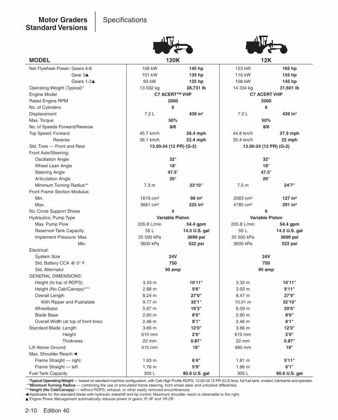
MODEL 120K 12KNet Flywheel Power: Gears 4-8 108 kW 145 hp 123 kW 165 hpNet Flywheel Power: Gear 3� 101 kW 135 hp 116 kW 155 hpNet Flywheel Power: Gears 1-2� 93 kW 125 hp 108 kW 145 hpOperating Weight (Typical)* 13 032 kg 28,731 lb 14 334 kg 31,601 lbEngine Model C7 ACERT™ VHP C7 ACERT VHPRated Engine RPM 2000 2000No. of Cylinders 6 6Displacement 7.2 L 439 in3 7.2 L 439 in3
Max. Torque 50% 50%No. of Speeds Forward/Reverse 8/6 8/6Top Speed: Forward 45.7 km/h 28.4 mph 44.8 km/h 27.9 mphTop Speed: Reverse 36.1 km/h 22.4 mph 35.4 km/h 22 mphStd. Tires — Front and Rear 13.00-24 (12 PR) (G-2) 13.00-24 (12 PR) (G-2)Front Axle/Steering:
Oscillation Angle 32° 32°Wheel Lean Angle 18° 18°Steering Angle 47.5° 47.5°Articulation Angle 20° 20°Minimum Turning Radius** 7.3 m 23'10" 7.5 m 24'7"
Front Frame Section Modulus:Min. 1619 cm² 99 in² 2083 cm² 127 in²Max. 3681 cm² 225 in² 4785 cm² 291 in²
No. Circle Support Shoes 4 6Hydraulics: Pump Type Variable Piston Variable Piston
Max. Pump Flow 205.8 L/min 54.4 gpm 205.8 L/min 54.4 gpmReservoir Tank Capacity 55 L 14.5 U.S. gal 55 L 14.5 U.S. galImplement Pressure: Max. 25 500 kPa 3699 psi 25 500 kPa 3699 psiImplement Pressure: Min. 3600 kPa 522 psi 3600 kPa 522 psi
Electrical:System Size 24V 24VStd. Battery CCA @ 0° F 750 750Std. Alternator 95 amp 95 amp
GENERAL DIMENSIONS:Height (to top of ROPS) 3.33 m 10'11" 3.32 m 10'11"Height (No Cab/Canopy)*** 2.88 m 9'6" 3.02 m 9'11"Overall Length 8.24 m 27'0" 8.47 m 27'9"
With Ripper and Pushplate 9.77 m 32'1" 10.01 m 32'10"Wheelbase 5.87 m 19'3" 6.09 m 20'0"Blade Base 2.60 m 8'6" 2.60 m 8'6"Overall Width (at top of front tires) 2.46 m 8'1" 2.46 m 8'1"
Standard Blade: Length 3.66 m 12'0" 3.66 m 12'0"Standard Blade: Height 610 mm 2'0" 610 mm 2'0"Standard Blade: Thickness 22 mm 0.87" 22 mm 0.87"Lift Above Ground 410 mm 16" 480 mm 19"Max. Shoulder Reach:�
Frame Straight — right 1.93 m 6'4" 1.81 m 5'11"Frame Straight — left 1.76 m 5'9" 1.86 m 6'1"
Fuel Tank Capacity 305 L 80.6 U.S. gal 305 L 80.6 U.S. gal
***Typical Operating Weight — based on standard machine configuration, with Cab High Profile ROPS, 13.00-24 12 PR (G-2) tires, full fuel tank, coolant, lubricants and operator.***Minimum Turning Radius — combining the use of articulated frame steering, front wheel steer and unlocked differential.***Height (No Cab/Canopy) — without ROPS, exhaust, or other easily removed encumbrances.� Applicable for the standard blade with hydraulic sideshift and tip control. Maximum shoulder reach is obtainable to the right.� Engine Power Management automatically reduces power in gears 1F-3F and 1R-2R.

Edition 40 2-11
2
Motor GradersStandard Versions
Specifications
MODEL 140K 160KNet Flywheel Power: Gears 4-8 142 kW 190 hp 154 kW 206 hpNet Flywheel Power: Gear 3� 135 kW 181 hp 147 kW 196 hpNet Flywheel Power: Gears 1-2� 127 kW 170 hp 139 kW 186 hpOperating Weight (Typical)* 14 768 kg 32,558 lb 15 785 kg 34,800 lbEngine Model C7 ACERT VHP C7 ACERT VHPRated Engine RPM 2000 2000No. of Cylinders 6 6Displacement 7.2 L 439 in3 7.2 L 439 in3
Max. Torque 46% 46%No. of Speeds Forward/Reverse 8/6 8/6Top Speed: Forward 46.8 km/h 29.1 mph 46.4 km/h 28.8 mphTop Speed: Reverse 37 km/h 23 mph 36.6 km/h 22.8 mphStd. Tires — Front and Rear 14.00-24 (12 PR) (G-2) 14.00-24 (12 PR) (G-2)Front Axle/Steering:
Oscillation Angle 32° 32°Wheel Lean Angle 18° 18°Steering Angle 47.5° 47.5°Articulation Angle 20° 20°Minimum Turning Radius** 7.5 m 24'7" 7.5 m 24'7"
Front Frame Section Modulus:Min. 2083 cm² 127 in² 2083 cm² 127 in²Max. 4785 cm² 291 in² 4785 cm² 291 in²
No. Circle Support Shoes 6 6Hydraulics: Pump Type Variable Piston Variable Piston
Max. Pump Flow 205.8 L/min 54.4 gpm 205.8 L/min 54.4 gpmReservoir Tank Capacity 55 L 14.5 U.S. gal 55 L 14.5 U.S. galImplement Pressure: Max. 25 500 kPa 3699 psi 25 500 kPa 3699 psiImplement Pressure: Min. 3600 kPa 522 psi 3600 kPa 522 psi
Electrical:System Size 24V 24VStd. Battery CCA @ 0° F 750 750Std. Alternator 95 amp 95 amp
GENERAL DIMENSIONS:Height (to top of ROPS) 3.35 m 11'0" 3.35 m 11'0"Height (No Cab/Canopy)*** 3.05 m 10'0" 3.05 m 10'0"Overall Length 8.50 m 27'11" 8.50 m 27'11"
With Ripper and Pushplate 10.01 m 32'10" 10.01 m 32'10"Wheelbase 6.09 m 20'0" 6.09 m 20'0"Blade Base 2.60 m 8'6" 2.55 m 8'4"Overall Width (at top of front tires) 2.48 m 8'2" 2.48 m 8'2"
Standard Blade: Length 3.66 m 12'0" 4.27 m 14'0"Standard Blade: Height 610 mm 2'0" 686 mm 2'3"Standard Blade: Thickness 22 mm 0.87" 25 mm 1"Lift Above Ground 480 mm 18.9" 452 mm 17.8"Max. Shoulder Reach:�
Frame Straight — right 1.98 m 6'6" 2.26 m 7'5"Frame Straight — left 1.90 m 6'3" 2.22 m 7'4"
Fuel Tank Capacity 305 L 80.6 U.S. gal 344 L 90.9 U.S. gal
***Typical Operating Weight — based on standard machine configuration, with Cab High Profile ROPS, 14.00-24 12 PR (G-2) tires, full fuel tank, coolant, lubricants and operator.***Minimum Turning Radius — combining the use of articulated frame steering, front wheel steer and unlocked differential.***Height (No Cab/Canopy) — without ROPS, exhaust, or other easily removed encumbrances.� Applicable for the standard blade with hydraulic sideshift and tip control. Maximum shoulder reach is obtainable to the right.� Engine Power Management automatically reduces power in gears 1F-3F and 1R-2R.
2-12 Edition 40
Motor GradersGlobal Versions
Specifications
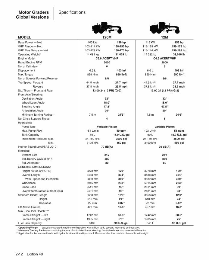
MODEL 120M 12MBase Power — Net 103 kW 138 hp 118 kW 158 hpVHP Range — Net 103-114 kW 138-153 hp 118-129 kW 158-173 hpVHP Plus Range — Net 103-129 kW 138-173 hp 118-144 kW 158-193 hpOperating Weight* 14 093 kg 31,069 lb 14 522 kg 32,016 lbEngine Model C6.6 ACERT VHP C6.6 ACERT VHPRated Engine RPM 2000 2000No. of Cylinders 6 6Displacement 6.6 L 403 in3 6.6 L 403 in3
Max. Torque 859 N·m 690 lb-ft 859 N·m 690 lb-ftNo. of Speeds Forward/Reverse 8/6 8/6Top Speed: Forward 44.5 km/h 27.7 mph 44.5 km/h 27.7 mphTop Speed: Reverse 37.8 km/h 23.5 mph 37.8 km/h 23.5 mphStd. Tires — Front and Rear 13.00 24 (12 PR) (G-2) 13.00 24 (12 PR) (G-2)Front Axle/Steering:
Oscillation Angle 32° 32°Wheel Lean Angle 18.0° 18.0°Steering Angle 47.5° 47.5°Articulation Angle 20° 20°Minimum Turning Radius** 7.5 m 24'6" 7.5 m 24'6"
No. Circle Support Shoes 4 6Hydraulics:
Pump Type Variable Piston Variable PistonMax. Pump Flow 151 L/min 40 gpm 193 L/min 51 gpmTank Capacity 60 L 15.9 U.S. gal 60 L 15.9 U.S. galImplement Pressure: Max. 24 150 kPa 3500 psi 24 150 kPa 3500 psiImplement Pressure: Min. 3100 kPa 450 psi 3100 kPa 450 psi
Interior Sound Level/SAE J919 70 dB(A) 70 dB(A)Electrical:
System Size 24V 24VStd. Battery CCA @ 0° F 880 880Std. Alternator 80 80
GENERAL DIMENSIONS:Height (to top of ROPS) 3278 mm 129" 3278 mm 129"Overall Length 8488 mm 334" 8488 mm 334"
With Ripper and Pushplate 9889 mm 389" 9889 mm 389"Wheelbase 5915 mm 233" 5915 mm 233"Blade Base 2511 mm 99" 2511 mm 99"Overal Width (at top of front tires) 2481 mm 98" 2481 mm 98"
Standard Blade: Length 3658 mm 12'0" 3658 mm 12'0"Standard Blade: Height 610 mm 24" 610 mm 24"Standard Blade: Thickness 22 mm 0.87" 22 mm 0.87"Lift Above Ground 427 mm 16.8" 427 mm 16.8"Max. Shoulder Reach:***
Frame Straight — left 1742 mm 68.6" 1742 mm 68.6"Frame Straight — right 1905 mm 75" 1905 mm 75"
Fuel Tank Capacity 340 L 90 U.S. gal 340 L 90 U.S. gal
***Operating Weight — based on standard machine configuration with full fuel tank, coolant, lubricants and operator.***Minimum Turning Radius — combining the use of articulated frame steering, front wheel steer and unlocked differential.***Applicable for the standard blade with hydraulic sideshift and tip control. Maximum shoulder reach is obtainable to the right.

Edition 40 2-13
2
Motor GradersGlobal Versions
Specifications
MODEL 140M 160MBase Power — Net 136 kW 183 hp 159 kW 213 hpVHP Range — Net 136-148 kW 183-198 hp 159-170 kW 213-228 hpVHP Plus Range — Net 136-163 kW 183-218 hp 159-185 kW 213-248 hpOperating Weight* 15 130 kg 33,356 lb 15 903 kg 35,060 lbEngine Model C7 ACERT VHP C9 ACERT VHPRated Engine RPM 2000 2000No. of Cylinders 6 6Displacement 7.2 L 439 in3 8.8 L 537 in3
Max. Torque 1079 N·m 796 lb-ft 1237 N·m 912 lb-ftNo. of Speeds Forward/Reverse 8/6 8/6Top Speed: Forward 46.6 km/h 29 mph 47.4 km/h 29.5 mphTop Speed: Reverse 36.8 km/h 22.9 mph 37.4 km/h 23.3 mphStd. Tires — Front and Rear 14.00 24 (10 PR) (G-2) 14.00 24 (10 PR) (G-2)Front Axle/Steering:
Oscillation Angle 32° 32°Wheel Lean Angle 18.0° 18.0°Steering Angle 47.5° 47.5°Articulation Angle 20° 20°Minimum Turning Radius** 7.75 m 25'6" 7.75 m 25'6"
No. Circle Support Shoes 6 6Hydraulics:
Pump Type Variable Piston Variable PistonMax. Pump Flow 210 L/min 55.7 gpm 210 L/min 55.7 gpmTank Capacity 60 L 15.9 U.S. gal 60 L 15.9 U.S. galImplement Pressure: Max. 24 150 kPa 3500 psi 24 150 kPa 3500 psiImplement Pressure: Min. 3100 kPa 450 psi 3100 kPa 450 psi
Interior Sound Level/SAE J919 70 dB(A) 70 dB(A)Electrical:
System Size 24V 24VStd. Battery CCA @ 0° F 880 880Std. Alternator 80 80
GENERAL DIMENSIONS:Height (to top of ROPS) 3293 mm 130" 3293 mm 130"Overall Length 8713 mm 343" 8713 mm 343"
With Ripper and Pushplate 10 144 mm 399" 10 144 mm 399"Wheelbase 6121 mm 241" 6121 mm 241"Blade Base 2552 mm 101" 2552 mm 101"Overal Width (at top of front tires) 2493 mm 98" 2493 mm 98"
Standard Blade: Length 3658 mm 12'0" 3658 mm 12'0"Standard Blade: Height 610 mm 24" 610 mm 24"Standard Blade: Thickness 22 mm 0.87" 22 mm 0.87"Lift Above Ground 480 mm 18.9" 452 mm 17.8"Max. Shoulder Reach:***
Frame Straight — left 1790 mm 70.5" 2090 mm 82.3"Frame Straight — right 1978 mm 77.9" 2278 mm 89.7"
Fuel Tank Capacity 416 L 110 U.S. gal 416 L 110 U.S. gal
***Operating Weight — based on standard machine configuration with full fuel tank, coolant, lubricants and operator.***Minimum Turning Radius — combining the use of articulated frame steering, front wheel steer and unlocked differential.***Applicable for the standard blade with hydraulic sideshift and tip control. Maximum shoulder reach is obtainable to the right.
2-14 Edition 40
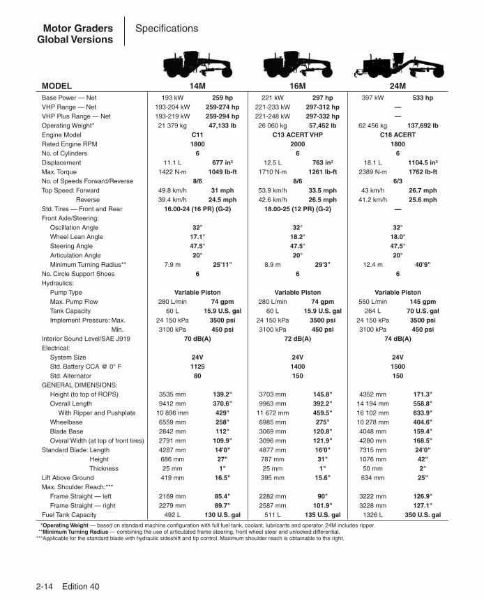
Motor GradersGlobal Versions
Specifications
MODEL 14M 16M 24MBase Power — Net 193 kW 259 hp 221 kW 297 hp 397 kW 533 hpVHP Range — Net 193-204 kW 259-274 hp 221-233 kW 297-312 hp —VHP Plus Range — Net 193-219 kW 259-294 hp 221-248 kW 297-332 hp —Operating Weight* 21 379 kg 47,133 lb 26 060 kg 57,452 lb 62 456 kg 137,692 lbEngine Model C11 C13 ACERT VHP C18 ACERTRated Engine RPM 1800 2000 1800No. of Cylinders 6 6 6Displacement 11.1 L 677 in3 12.5 L 763 in3 18.1 L 1104.5 in3
Max. Torque 1422 N·m 1049 lb-ft 1710 N·m 1261 lb-ft 2389 N·m 1762 lb-ftNo. of Speeds Forward/Reverse 8/6 8/6 6/3Top Speed: Forward 49.8 km/h 31 mph 53.9 km/h 33.5 mph 43 km/h 26.7 mphTop Speed: Reverse 39.4 km/h 24.5 mph 42.6 km/h 26.5 mph 41.2 km/h 25.6 mphStd. Tires — Front and Rear 16.00-24 (16 PR) (G-2) 18.00-25 (12 PR) (G-2) —Front Axle/Steering:
Oscillation Angle 32° 32° 32°Wheel Lean Angle 17.1° 18.2° 18.0°Steering Angle 47.5° 47.5° 47.5°Articulation Angle 20° 20° 20°Minimum Turning Radius** 7.9 m 25'11" 8.9 m 29'3" 12.4 m 40'9"
No. Circle Support Shoes 6 6 6Hydraulics:
Pump Type Variable Piston Variable Piston Variable PistonMax. Pump Flow 280 L/min 74 gpm 280 L/min 74 gpm 550 L/min 145 gpmTank Capacity 60 L 15.9 U.S. gal 60 L 15.9 U.S. gal 264 L 70 U.S. galImplement Pressure: Max. 24 150 kPa 3500 psi 24 150 kPa 3500 psi 24 150 kPa 3500 psiImplement Pressure: Min. 3100 kPa 450 psi 3100 kPa 450 psi 3100 kPa 450 psi
Interior Sound Level/SAE J919 70 dB(A) 72 dB(A) 74 dB(A)Electrical:
System Size 24V 24V 24VStd. Battery CCA @ 0° F 1125 1400 1500Std. Alternator 80 150 150
GENERAL DIMENSIONS:Height (to top of ROPS) 3535 mm 139.2" 3703 mm 145.8" 4352 mm 171.3"Overall Length 9412 mm 370.6" 9963 mm 392.2" 14 194 mm 558.8"
With Ripper and Pushplate 10 896 mm 429" 11 672 mm 459.5" 16 102 mm 633.9"Wheelbase 6559 mm 258" 6985 mm 275" 10 278 mm 404.6"Blade Base 2842 mm 112" 3069 mm 120.8" 4048 mm 159.4"Overal Width (at top of front tires) 2791 mm 109.9" 3096 mm 121.9" 4280 mm 168.5"
Standard Blade: Length 4287 mm 14'0" 4877 mm 16'0" 7315 mm 24'0"Standard Blade: Height 686 mm 27" 787 mm 31" 1076 mm 42"Standard Blade: Thickness 25 mm 1" 25 mm 1" 50 mm 2"Lift Above Ground 419 mm 16.5" 395 mm 15.6" 634 mm 25"Max. Shoulder Reach:***
Frame Straight — left 2169 mm 85.4" 2282 mm 90" 3222 mm 126.9"Frame Straight — right 2279 mm 89.7" 2587 mm 101.9" 3228 mm 127.1"
Fuel Tank Capacity 492 L 130 U.S. gal 511 L 135 U.S. gal 1326 L 350 U.S. gal
***Operating Weight — based on standard machine configuration with full fuel tank, coolant, lubricants and operator. 24M includes ripper.***Minimum Turning Radius — combining the use of articulated frame steering, front wheel steer and unlocked differential.***Applicable for the standard blade with hydraulic sideshift and tip control. Maximum shoulder reach is obtainable to the right.
Edition 40 2-15
2
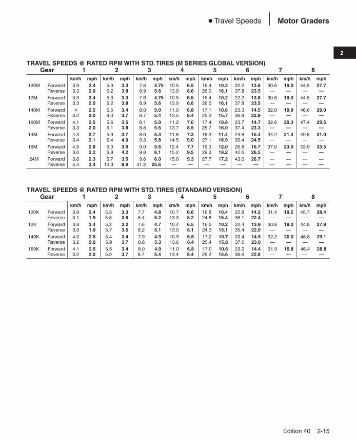
Motor Graders● Travel Speeds
TRAVEL SPEEDS @ RATED RPM WITH STD. TIRES (M SERIES GLOBAL VERSION)Gear 1 2 3 4 5 6 7 8
km/h mph km/h mph km/h mph km/h mph km/h mph km/h mph km/h mph km/h mph120M Forward 3.9 2.4 5.3 3.3 7.6 4.75 10.5 6.5 16.4 10.2 22.2 13.8 30.6 19.0 44.5 27.7
Reverse 3.3 2.0 6.2 3.8 8.9 5.60 13.9 8.6 26.0 16.1 37.8 23.5 — — — —12M Forward 3.9 2.4 5.3 3.3 7.6 4.75 10.5 6.5 16.4 10.2 22.2 13.8 30.6 19.0 44.5 27.7
Reverse 3.3 2.0 6.2 3.8 8.9 5.60 13.9 8.6 26.0 16.1 37.8 23.5 — — — —140M Forward 4 2.5 5.5 3.4 8.0 5.00 11.0 6.8 17.1 10.6 23.3 14.5 32.0 19.9 46.6 29.0
Reverse 3.2 2.0 6.0 3.7 8.7 5.40 13.5 8.4 25.3 15.7 36.8 22.9 — — — —160M Forward 4.1 2.5 5.6 3.5 8.1 5.00 11.2 7.0 17.4 10.8 23.7 14.7 32.6 20.3 47.4 29.5
Reverse 3.3 2.0 6.1 3.8 8.8 5.50 13.7 8.5 25.7 16.0 37.4 23.3 — — — —14M Forward 4.3 2.7 5.9 3.7 8.6 5.30 11.8 7.3 18.3 11.4 24.8 15.4 34.2 21.3 49.8 31.0
Reverse 3.4 2.1 6.4 4.0 9.3 5.80 14.5 9.0 27.1 16.9 39.4 24.5 — — — —16M Forward 4.5 2.8 6.3 3.9 9.0 5.60 12.4 7.7 19.3 12.0 26.8 16.7 37.0 23.0 53.9 33.5
Reverse 3.6 2.2 6.8 4.2 9.8 6.10 15.2 9.5 29.3 18.2 42.6 26.5 — — — —24M Forward 3.6 2.3 5.7 3.5 9.6 6.00 15.0 9.3 27.7 17.2 43.0 26.7 — — — —
Reverse 5.4 3.4 14.3 8.9 41.2 25.60 — — — — — — — — — —
TRAVEL SPEEDS @ RATED RPM WITH STD. TIRES (STANDARD VERSION)Gear 1 2 3 4 5 6 7 8
km/h mph km/h mph km/h mph km/h mph km/h mph km/h mph km/h mph km/h mph120K Forward 3.9 2.4 5.3 3.3 7.7 4.8 10.7 6.6 16.8 10.4 22.8 14.2 31.4 19.5 45.7 28.4
Reverse 3.1 1.9 5.8 3.6 8.4 5.2 13.3 8.2 24.8 15.4 36.1 22.4 — — — —12K Forward 3.8 2.4 5.2 3.2 7.6 4.7 10.4 6.5 16.5 10.2 22.4 13.9 30.8 19.2 44.8 27.9
Reverse 3.0 1.9 5.7 3.5 8.2 5.1 13.0 8.1 24.3 15.1 35.4 22.0 — — — —140K Forward 4.0 2.5 5.4 3.4 7.9 4.9 10.9 6.8 17.2 10.7 23.4 14.5 32.2 20.0 46.8 29.1
Reverse 3.2 2.0 5.9 3.7 8.6 5.3 13.6 8.4 25.4 15.8 37.0 23.0 — — — —160K Forward 4.1 2.5 5.5 3.4 8.0 4.9 11.0 6.8 17.0 10.6 23.2 14.4 31.9 19.8 46.4 28.8
Reverse 3.2 2.0 5.9 3.7 8.7 5.4 13.4 8.4 25.2 15.6 36.6 22.8 — — — —
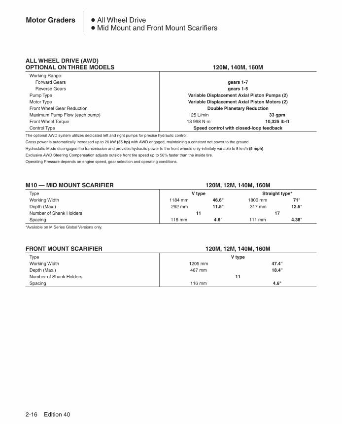
ALL WHEEL DRIVE (AWD)OPTIONAL ON THREE MODELS 120M, 140M, 160M
Working Range:Forward Gears gears 1-7Reverse Gears gears 1-5
Pump Type Variable Displacement Axial Piston Pumps (2)Motor Type Variable Displacement Axial Piston Motors (2)Front Wheel Gear Reduction Double Planetary ReductionMaximum Pump Flow (each pump) 125 L/min 33 gpmFront Wheel Torque 13 998 N·m 10,325 lb-ftControl Type Speed control with closed-loop feedback
The optional AWD system utilizes dedicated left and right pumps for precise hydraulic control.
Gross power is automatically increased up to 26 kW (35 hp) with AWD engaged, maintaining a constant net power to the ground.
Hydrostatic Mode disengages the transmission and provides hydraulic power to the front wheels only-infinitely variable to 8 km/h (5 mph).
Exclusive AWD Steering Compensation adjusts outside front tire speed up to 50% faster than the inside tire.
Operating Pressure depends on engine speed, gear selection and operating conditions.
M10 — MID MOUNT SCARIFIER 120M, 12M, 140M, 160MType V type Straight type*Working Width 1184 mm 46.6" 1800 mm 71"Depth (Max.) 292 mm 11.5" 317 mm 12.5"Number of Shank Holders 11 17Spacing 116 mm 4.6" 111 mm 4.38"
*Available on M Series Global Versions only.
FRONT MOUNT SCARIFIER 120M, 12M, 140M, 160MType V typeWorking Width 1205 mm 47.4"Depth (Max.) 467 mm 18.4"Number of Shank Holders 11Spacing 116 mm 4.6"
2-16 Edition 40
Motor Graders ● All Wheel Drive● Mid Mount and Front Mount Scarifiers
Edition 40 2-17
2
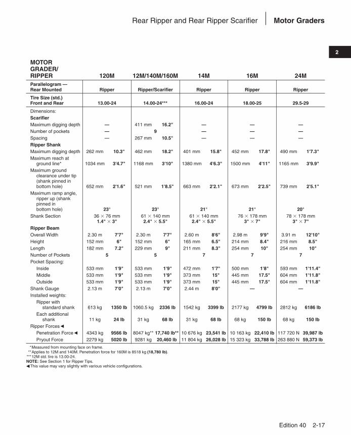
Motor GradersRear Ripper and Rear Ripper Scarifier
MOTOR GRADER/RIPPER 120M 12M/140M/160M 14M 16M 24MParallelogram — Rear Mounted Ripper Ripper/Scarifier Ripper Ripper Ripper
Tire Size (std.) Front and Rear 13.00-24 14.00-24*** 16.00-24 18.00-25 29.5-29
Dimensions:ScarifierMaximum digging depth — 411 mm 16.2" — — —Number of pockets — 9 — — —Spacing — 267 mm 10.5" — — —Ripper ShankMaximum digging depth 262 mm 10.3" 462 mm 18.2" 401 mm 15.8" 452 mm 17.8" 490 mm 1'7.3"Maximum reach at
ground line* 1034 mm 3'4.7" 1168 mm 3'10" 1380 mm 4'6.3" 1500 mm 4'11" 1165 mm 3'9.9"Maximum ground
clearance under tip(shank pinned in bottom hole) 652 mm 2'1.6" 521 mm 1'8.5" 663 mm 2'2.1" 673 mm 2'2.5" 739 mm 2'5.1"
Maximum ramp angle, ripper up (shank pinned in bottom hole) 23° 23° 21° 21° 20°
Shank Section 36 � 76 mm 61 � 140 mm 61 � 140 mm 76 � 178 mm 78 � 178 mm1.4" � 3" 2.4" � 5.5" 2.4" � 5.5" 3" � 7" 3" � 7"
Ripper BeamOverall Width 2.30 m 7'7" 2.30 m 7'7" 2.60 m 8'6" 2.98 m 9'9" 3.91 m 12'10"Height 152 mm 6" 152 mm 6" 165 mm 6.5" 214 mm 8.4" 216 mm 8.5"Length 182 mm 7.2" 229 mm 9" 211 mm 8.3" 254 mm 10" 254 mm 10"Number of Pockets 5 5 7 7 7Pocket Spacing:
Inside 533 mm 1'9" 533 mm 1'9" 472 mm 1'7" 500 mm 1'8" 593 mm 1'11.4"Middle 533 mm 1'9" 533 mm 1'9" 373 mm 15" 445 mm 17.5" 604 mm 1'11.8"Outside 533 mm 1'9" 533 mm 1'9" 373 mm 15" 445 mm 17.5" 604 mm 1'11.8"
Shank Gauge 2.13 m 7'0" 2.13 m 7'0" 2.44 m 8'0" — —Installed weights:
Ripper with standard shank 613 kg 1350 lb 1060.5 kg 2336 lb 1542 kg 3399 lb 2177 kg 4799 lb 2812 kg 6186 lb
Each additional shank 11 kg 24 lb 31 kg 68 lb 31 kg 68 lb 68 kg 150 lb 68 kg 150 lb
Ripper Forces �
Penetration Force � 4343 kg 9566 lb 8047 kg** 17,740 lb** 10 676 kg 23,541 lb 10 163 kg 22,410 lb 117 720 N 39,987 lbPryout Force 2279 kg 5020 lb 9281 kg 20,460 lb 11 804 kg 26,028 lb 15 323 kg 33,788 lb 263 880 N 59,373 lb
*Measured from mounting face on frame.**Applies to 12M and 140M. Penetration force for 160M is 8518 kg (18,780 lb).
***12M std. tire is 13.00-24.NOTE: See Section 1 for Ripper Tips.� This value may vary slightly with various vehicle configurations.

2-18 Edition 40
Motor Graders Production
PRODUCTIONThe motor grader is used in a variety of applications
in a variety of industries. Therefore, there are manyways to measure its operating capacity, or production.One method expresses a motor grader’s productionin relation to the area covered by the moldboard.
Formula:A = S � (Le � Lo) � 1000 � E (Metric)A = S � (Le � Lo) � 5280 � E (English)
where A: Hourly operating area (m2/h or ft2/h)S: Operating speed (km/h or mph)
Le: Effective blade length (m or ft)Lo: Width of overlap (m or ft)E: Job efficiency
Operating Speeds:Typical operating speeds by application
Finish Grading: 0-4 km/h (0-2.5 mph)Heavy Blading: 0-9 km/h (0-6 mph)Ditch Repair: 0-5 km/h (0-3 mph)Ripping: 0-5 km/h (0-3 mph)Road Maintenance: 5-16 km/h (3-9.5 mph)Haul Road Maintenance: 5-16 km/h (3-9.5 mph)Snow Plowing: 7-21 km/h (4-13 mph)Snow Winging: 15-28 km/h (9-17 mph)
Effective Blade Length:Since the moldboard is usually angled when mov-
ing material, an effective blade length must be com-puted to account for this angle. This is the actualwidth of material swept by the moldboard.
NOTE: Angles are measured as shown below. Theeffective length becomes shorter as the angleincreases.
Moldboard Angle
0°

Edition 40 2-19
2
Motor GradersProduction
Effective Length, Effective Length,Moldboard m (ft) m (ft)
Length, 30 degree 45 degreem (ft) blade angle blade angle
3.658 (12) 3.17 (10.4) 2.59 (8.5)3.962 (13) 3.43 (11.3) 2.80 (9.2)4.267 (14) 3.70 (12.1) 3.02 (9.9)4.877 (16) 4.22 (13.9) 3.45 (11.3)7.315 (24) 6.33 (20.8) 5.17 (17.0)
For other blade lengths and carry angles:Effective length = COS [Radians (Blade L)] � Blade Length
Width of Overlap:The width of overlap is generally 0.6 m (2.0 ft).
This overlap accounts for the need to keep the tiresout of the windrow on the return pass.
Job Efficiency:Job efficiencies vary based on job conditions, oper-
ator skill, etc.A good estimation for efficiency is approximately
0.70 to 0.85, but actual operating conditions shouldbe used to determine the best value.
Example problem:
A 140M motor grader with a 3.66 m (12 ft) mold-board is performing road maintenance on a town-ship road. The machine is working at an averagespeed of 13 km/h (8 mph) with a moldboard carryangle of 30 degrees. What is the motor grader’s pro-duction based on coverage area?
Note: Due to the long passes involved in road main-tenance — fewer turnarounds — a higher jobefficiency of 0.90 is chosen.
Solution:From the table, the effective blade length is 3.17 m
(10.4 ft).
MetricProduction, A = 13 km/h � (3.17 m � 0.6 m) �
1000 � 0.90Production, A = 30 069 m2/hr (3.07 hectares/hr)
EnglishProduction, A = 8 mph � (10.4 ft � 2.0 ft) �
5280 � 0.90Production, A = 319,334 ft2/hr (7.33 acres/hr)
2-20 Edition 40
Motor Graders Production
Figure 1
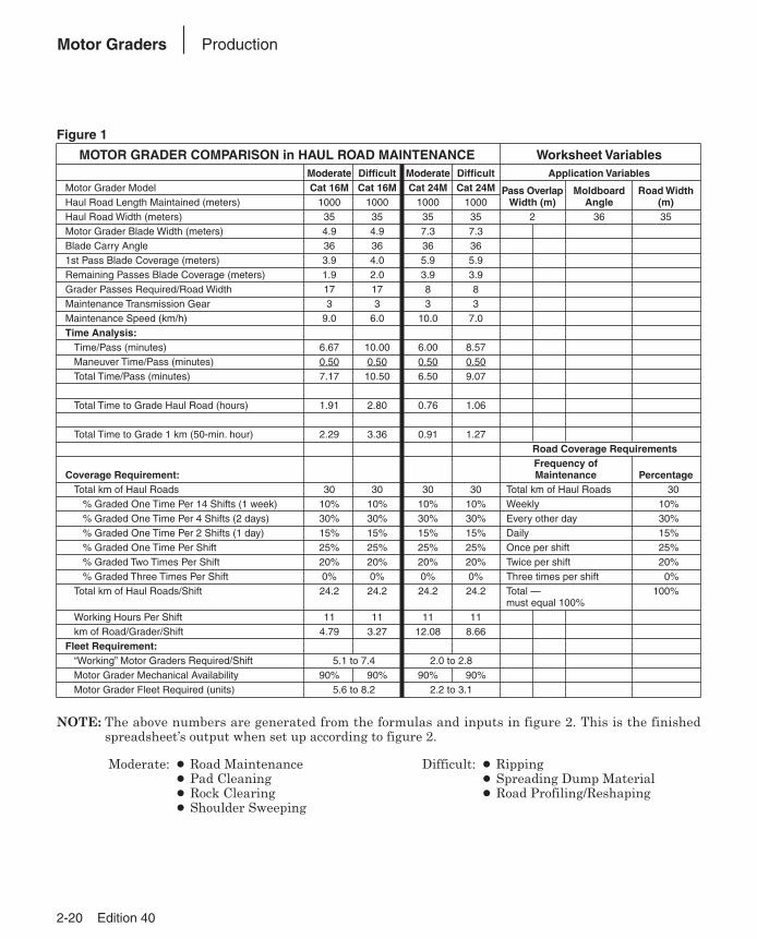
MOTOR GRADER COMPARISON in HAUL ROAD MAINTENANCE Worksheet VariablesModerate Difficult Moderate Difficult Application Variables
Motor Grader Model Cat 16M Cat 16M Cat 24M Cat 24M Pass Overlap Moldboard Road WidthHaul Road Length Maintained (meters) 1000 1000 1000 1000 Width (m) Angle (m)Haul Road Width (meters) 35 35 35 35 2 36 35Motor Grader Blade Width (meters) 4.9 4.9 7.3 7.3Blade Carry Angle 36 36 36 361st Pass Blade Coverage (meters) 3.9 4.0 5.9 5.9Remaining Passes Blade Coverage (meters) 1.9 2.0 3.9 3.9Grader Passes Required/Road Width 17 17 8 8Maintenance Transmission Gear 3 3 3 3Maintenance Speed (km/h) 9.0 6.0 10.0 7.0Time Analysis:
Time/Pass (minutes) 6.67 10.00 6.00 8.57Maneuver Time/Pass (minutes) 0.50 0.50 0.50 0.50Total Time/Pass (minutes) 7.17 10.50 6.50 9.07
Total Time to Grade Haul Road (hours) 1.91 2.80 0.76 1.06
Total Time to Grade 1 km (50-min. hour) 2.29 3.36 0.91 1.27Road Coverage RequirementsFrequency of
Coverage Requirement: Maintenance PercentageTotal km of Haul Roads 30 30 30 30 Total km of Haul Roads 30
% Graded One Time Per 14 Shifts (1 week) 10% 10% 10% 10% Weekly 10%% Graded One Time Per 4 Shifts (2 days) 30% 30% 30% 30% Every other day 30%% Graded One Time Per 2 Shifts (1 day) 15% 15% 15% 15% Daily 15%% Graded One Time Per Shift 25% 25% 25% 25% Once per shift 25%% Graded Two Times Per Shift 20% 20% 20% 20% Twice per shift 20%% Graded Three Times Per Shift 0% 0% 0% 0% Three times per shift 0%
Total km of Haul Roads/Shift 24.2 24.2 24.2 24.2 Total — 100%must equal 100%
Working Hours Per Shift 11 11 11 11km of Road/Grader/Shift 4.79 3.27 12.08 8.66
Fleet Requirement:“Working” Motor Graders Required/Shift 5.1 to 7.4 2.0 to 2.8Motor Grader Mechanical Availability 90% 90% 90% 90%Motor Grader Fleet Required (units) 5.6 to 8.2 2.2 to 3.1
NOTE: The above numbers are generated from the formulas and inputs in figure 2. This is the finishedspreadsheet’s output when set up according to figure 2.
NOTE: Moderate: ● Road Maintenance Difficult: ● Ripping● Pad Cleaning ● Spreading Dump Material● Rock Clearing ● Road Profiling/Reshaping● Shoulder Sweeping
Edition 40 2-21
2
Motor GradersProduction
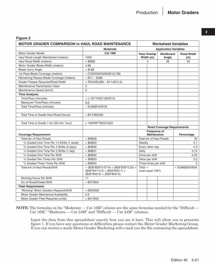
Figure 2
MOTOR GRADER COMPARISON in HAUL ROAD MAINTENANCE Worksheet VariablesModerate Application Variables
Motor Grader Model Cat 16M Pass Overlap Moldboard Road WidthHaul Road Length Maintained (meters) 1000 Width (m) Angle (m)Haul Road Width (meters) = $M$8 2 36 35Motor Grader Blade Width (meters) 4.88Blade Carry Angle = $L$81st Pass Blade Coverage (meters) = COS(RADIANS(B10))*B9Remaining Passes Blade Coverage (meters) = B11 – $J$8Grader Passes Required/Road Width = ROUND((B8 – B11)/B12,0)Maintenance Transmission Gear 3Maintenance Speed (km/h) 9Time Analysis:
Time/Pass (minutes) = (+ B7/1000)*(60/B15)Maneuver Time/Pass (minutes) 0.5Total Time/Pass (minutes) = SUM(B18:B19)
Total Time to Grade Haul Road (hours) = B13*B20/60
Total Time to Grade 1 km (50-min. hour) = 1000/B7*B22/0.833Road Coverage Requirements
Frequency of Coverage Requirement: Maintenance Percentage
Total km of Haul Roads = $M$28 Total km of Haul Roads 30% Graded One Time Per 14 Shifts (1 week) = $M$29 Weekly 0.1% Graded One Time Per 4 Shifts (2 days) = $M$30 Every other day 0.3% Graded One Time Per 2 Shifts (1 day) = $M$31 Daily 0.15% Graded One Time Per Shift = $M$32 Once per shift 0.25% Graded Two Times Per Shift = $M$33 Twice per shift 0.2% Graded Three Times Per Shift = $M$34 Three times per shift 0
Total km of Haul Roads/Shift = (B28*B29*0.0714) + (B28*B30*0.25) + Total — = SUM(M29:M34)(B28*B31*0.5) + (B28*B32*1) + must equal 100%(B28*B33*2) + (B28*B34*3)
Working Hours Per Shift 11km of Road/Grader/Shift = B37/B24
Fleet Requirement:“Working” Motor Graders Required/Shift = B35/B38Motor Grader Mechanical Availability 0.9Motor Grader Fleet Required (units) = B41/B42
NOTE: The formulas in the “Moderate — Cat 16M” column are the same formulas needed for the “Difficult —Cat 16M,” “Moderate — Cat 24M” and “Difficult — Cat 24M” columns.
NOTE: Input the data from this spreadsheet exactly how you see it here. This will allow you to generate figure 1. If you have any questions or difficulties please contact the Motor Grader Marketing Group.If you can receive e-mails Motor Grader Marketing will e-mail you the file containing the spreadsheet.

2-22 Edition 40
Motor Graders Formulas
BLADE PULLThis specification is also known as drawbar pull.
This spec can be calculated as follows:Variables:Rear weight of machine = WrTire traction coefficient = T (Look up the table entitled
“Coefficient of Traction Factors”)Wr � T = Blade Pull
Example problem:
Calculate the blade pull for a 140M Global Versionversion machine operating in a quarry pit...MetricRW = 10 501 kgT = 0.65
10 501 � 0.65 = 6825.65EnglishRW = 23,151 lbT = 0.65
23,151 � 0.65 = 15,048.15
BLADE DOWN PRESSUREThis spec can be calculated as follows:
Variables:Blade to front axle length = BAWheel base length = WBWeight on front wheels = FWBlade down pressure = BD
Example problem:
Calculate the blade down pressure for a 140MGlobal Version version machine...MetricBA = 2565 mm FW = 4223 kgWB = 6086 mm BD = ?
EnglishBA = 101 in FW = 9310 lbWB = 240 in BD = ?
This specification is only a minor indicator of amotor grader’s productivity. It alone gives no mea-sure of overall machine productivity. When consid-ering motor grader production you need an optimumbalance between the machine’s front and rearweights. If a machine has too much weight on thefront axle it might have a high blade down pressurespec, however it will lack the essential rear weightand traction needed to push through the load. Toomuch weight in the rear and it will not have the nec-essary weight in the front during heavy cuts to main-tain proper steering control.
Cat machines are built with this optimum bal-ance in mind. A Cat motor grader is engineered withthe proper weight distribution necessary for maxi-mum productivity.
Effective Blade Length*Moldboard
3.66 m (12') 4.27 m (14') 4.88 m (16') 7.32 m (24')
m ft m ft m ft m ft0° 3.66 12.00 4.27 14.00 4.88 16.00 7.32 24.005° 3.64 11.95 4.25 13.95 4.86 15.94 7.29 23.9110° 3.60 11.82 4.20 13.79 4.80 15.76 7.21 23.6415° 3.53 11.59 4.12 13.52 4.71 15.45 7.07 23.1820° 3.44 11.28 4.01 13.16 4.58 15.04 6.87 22.5525° 3.32 10.88 3.87 12.69 4.42 14.50 6.63 21.7530° 3.17 10.39 3.69 12.12 4.22 13.86 6.33 20.7835° 3.00 9.83 3.50 11.47 4.00 13.11 5.99 19.6640° 2.80 9.19 3.27 10.72 3.74 12.26 5.61 18.3945° 2.59 8.49 3.02 9.90 3.45 11.31 5.17 16.97
*Effective blade length is the amount of blade coverage the machine is capableof when the blade is at a given angle.
9310 = 16,075 lb�240
(240 – 101)
4223 = 7299 kg�6086
(6086 – 2565)
FW = BD�WB
(WB – BA)
An
gle
°
Edition 40 2-23
2
Motor GradersExtreme Slope Operation
EXTREME SLOPE OPERATIONThere are two ways of defining slope work. The
slope perpendicular to the machines direction oftravel is commonly referred to as “Side Sloping.” Theslope parallel to the machines direction of travel —the machines ability to travel up or down terrain,is commonly referred to as “Gradeability.”
Side Sloping capability for our M-Series gradersis somewhat subjective but general agreementamong professional operators is that working on aslope ratio of 2.5:1 (21.8 degrees) is the safe limit …an experienced operator may be able to operate ona 2:1 (28 degrees) slope. There are many factors,which influence this limit, such as operator experi-ence, machine configuration, tires, soil conditions,but a 2.5:1 is achievable. Further, a 3:1 slope is theapproximate maximum side slope a grader can workon in straight frame configuration. The steeper sideslopes all require the machine to be articulated tosafely negotiate the slope.
Gradeability is approximately 22 degrees. This isestablished by the graders ability to stop withoutskid ding the tires while moving downhill. The motorgrader can, however, climb grades steeper than22 degrees. The traction coefficient is the criticalfactor in determining whether a grader can safelynegotiate the slope. Caterpillar recommends thatyou never climb a slope steeper than you can safelydescend.
Maximum lubrication angle: We have measuredthe graders on a tilt table and pump cavitation occursaround 45 degrees (100% or 1:1). This is beyond thegrade or slope a motor grader can operate on.
When working side hills and slopes, considerationshould be given to the following important points.● Speed of Travel — At higher speeds, inertia forces
tend to make the grader less stable.
● Roughness of Terrain or Surface — Ampleallowance should be made where the terrain orsurface is uneven.
● Mounted Equipment — Mounted attachmentssuch as front plows, snow wings, rippers and othermounted equipment cause the tractor to balancedifferently.
● Nature of Surface — New earthen fills may giveway with the weight of the grader. Rocky surfacesmay promote side slipping of grader.
● Wheel Slippage Due to Excessive Loads orSide Draft — This may cause downhill tire to“dig in,” increasing the angle of grader.
● Tire Selection and Maintenance — Considera -tion should be given to proper tire selection andair pressure. Consult with Caterpillar publication— Motor Grader Tire Selection Guide and Opera -tion and Maintenance manual for more information.
● Drawbar, Circle and Blade Position — Theposition of the blade can affect the stability of themachine.
● Articulation Angle — Articulation angle canaffect the stability of the machine.
● Wheel Lean Angle — Wheel lean angle can affectthe stability of the machine.
NOTE: Safe operation on steep slopes may requirespecial machine maintenance as well asexcel lent operator skill and proper equip-ment setup for the specific application.Consult Operation & Maintenance Manual,Caterpillar publication — Motor GraderApplication Guide, and the Grade Com pari -son Chart in the Tables section of this Perfor -mance Hand book, for further operating tips.

2-24 Edition 40
Motor Graders Work Tools
Work Tool 120M 12M 140M 160M 14M 16M 24MLift Group x x x x x x —
V-Plow x x x x x x —
One Way Plow x x x x x x —
Manual Reversible Plow x x x x x x —
Hydraulic Reversible Plow x x x x x x —
Snow Wing x x x x x x —
Mid Mount Scarifier x x x x — — —
Front Scarifier x x x x — — —
Manual Angle Blade x x x x x x —
Hydraulic Angle Blade x x x x x x —
Straight Blade x x x x x x —
This list is not all inclusive.
See Price Lists, Cat Work Tools (CWT) Price List, and your Cat dealer for special attachment needs.
Attachments for Cat motor graders require additional hydraulics.
Most front-mounted attachments require a Quick Attach-Detach Parallel Lift Group.
Contact your Cat dealer for details.