Scope of Work - Passaic River Public Digital Library
118
Transcript of Scope of Work - Passaic River Public Digital Library


LOWER PASSAIC RIVER RESTORATION PROJECT
REVISED PRELIMINARY DRAFT FIELD SAMPLING PLAN, VOLUME 3
TABLE OF CONTENTS
1.0 Introduction................................................................................................................ 1-1
1.1. Project Background........................................................................................... 1-4
1.2. Conceptual Site Model...................................................................................... 1-4
1.3. Candidate Restoration Sites .............................................................................. 1-5
1.4. Field Sampling Plan Volume 3 Contents.......................................................... 1-6
2.0 General Field Requirements ...................................................................................... 2-1
2.1. Mobilization/Demobilization............................................................................ 2-1
2.2. Site Facilities..................................................................................................... 2-1
2.3. Health And Safety............................................................................................. 2-2
2.4. Equipment Decontamination ............................................................................ 2-2
2.5. Sample Management......................................................................................... 2-2
2.6. Standard Operating Procedures......................................................................... 2-4
2.7. Quality Control and Quality Assurance............................................................ 2-4
3.0 Existing Data Gaps .................................................................................................... 3-1
3.1. Bathymetry........................................................................................................ 3-1
3.2. Topography and Other Map Data ..................................................................... 3-2
3.3. Geophysical Data .............................................................................................. 3-3
3.4. Geotechnical Data............................................................................................. 3-4
3.5. Soils and Sediments Geochemistry................................................................... 3-4
3.6. Water Quality.................................................................................................... 3-6
3.6.1. Surface Water Quality.............................................................................. 3-6
3.6.2. Groundwater Quality ............................................................................... 3-7
3.6.3. Water Quality Data Gaps and Recommendations ................................... 3-8
3.7. Hydrology and Hydrodynamics........................................................................ 3-8
Field Sampling Plan Volume 3 Revised Preliminary Draft Lower Passaic River Restoration Project i July 2005

3.8. Cultural Resources .......................................................................................... 3-11
3.9. Socioeconomics and Real Estate .................................................................... 3-12
4.0 Field Tasks ................................................................................................................. 4-1
4.1. Task 1 – Bathymetric and Aerial Surveys (PMP Tasks JAA and JDE) ........... 4-1
4.1.1. Data Needs and Survey Objectives.......................................................... 4-1
4.1.2. Bathymetric and Aerial Surveys Scope ................................................... 4-2
4.1.3. Bathymetric and Aerial Survey Reporting............................................... 4-4
4.2. Task 2 - Supplemental Land Survey (PMP Task JAAA) ................................. 4-6
4.2.1. Data Needs and Survey Objectives.......................................................... 4-6
4.2.2. Land Surveying Scope ............................................................................. 4-7
4.2.3. Preliminary Land Survey Methods .......................................................... 4-8
4.2.4. Land Survey Reporting............................................................................ 4-9
4.3. Task 3 – Geophysical Survey (PMP Task JAAD).......................................... 4-11
4.3.1. Data Needs and Survey Objectives........................................................ 4-11
4.3.2. Geophysical Surveying Scope ............................................................... 4-12
4.3.3. Preliminary Geophysical Survey Methods ............................................ 4-12
4.3.4. Geophysical Survey Reporting .............................................................. 4-23
4.4. Task 4 –Soils and Sediments Investigations (PMP Tasks JAC and JFB)....... 4-25
4.4.1. Data Needs and Sampling Objectives.................................................... 4-25
4.4.2. Sampling Locations and Frequency....................................................... 4-27
4.4.3. Preliminary Soil and Sediment Methods ............................................... 4-28
4.4.4. Sample Analysis and Reporting............................................................. 4-33
4.5. Task 5 –Water Quality Investigations (PMP Tasks JAAB and JFB) ............. 4-34
4.5.1. Data Needs and Sampling Objectives.................................................... 4-34
4.5.2. Sampling Locations and Frequency....................................................... 4-34
4.5.3. Preliminary Water Quality Methods...................................................... 4-35
4.5.4. Sample Analysis and Reporting............................................................. 4-43
4.6. Task 6 –Hydrologic & Hydrodynamic (PMP Tasks JAB and JFB) ............... 4-44
4.6.1. Data Needs and Sampling Objectives.................................................... 4-44
Field Sampling Plan Volume 3 Revised Preliminary Draft Lower Passaic River Restoration Project ii July 2005

4.6.2. Sample Locations and Frequency .......................................................... 4-45
4.6.3. Preliminary Hydrologic & Hydrodynamic Methods ............................. 4-45
4.6.4. Hydrologic & Hydrodynamic Reporting ............................................... 4-47
4.7. Task 7 – Cultural Resources (PMP Task JG) ................................................. 4-47
4.7.1. Data Needs and Study Objectives.......................................................... 4-48
4.7.2. Preliminary Cultural Resource Methods................................................ 4-49
4.7.3. Cultural Resource Reporting.................................................................. 4-52
4.8. Task 8 – Socioeconomics (PMP Task JB)...................................................... 4-52
4.8.1. Data Needs and Objectives .................................................................... 4-53
4.8.2. Preliminary Socioeconomic Methods .................................................... 4-53
4.8.3. Socioeconomic Reporting...................................................................... 4-58
4.9. Task 9 - Real Estate (PMP Task JC)............................................................... 4-58
4.9.1. Data Needs and Objectives .................................................................... 4-59
4.9.2. Preliminary Real Estate Methods........................................................... 4-60
5.0 Acronyms................................................................................................................... 5-1
6.0 References.................................................................................................................. 6-1
Field Sampling Plan Volume 3 Revised Preliminary Draft Lower Passaic River Restoration Project iii July 2005

TABLE OF TABLES AND FIGURES
Figure 1-1 Site Location Map
Table 3-1 Available Bathymetric Data
Table 4-1 Summary of Field Tasks
Table 4-2 Guidance for Land Surveying
Table 4-3 Measurement Quality Objectives
Appendix A HTRW Drilling Log Form
Appendix B Soil Summary Sheet
Appendix C HTRW Well Installation Diagram
Appendix D Well Development Form
Appendix E HTRW Well Sampling Form
Field Sampling Plan Volume 3 Revised Preliminary Draft Lower Passaic River Restoration Project iv July 2005

1.0 INTRODUCTION
Field Sampling Plan (FSP) Volume 3 presents the technical approach for
conducting site characterization activities for the Lower Passaic River Restoration Project
(LPRRP). This FSP document addresses the following programs:
• Bathymetric and aerial surveys.
• Supplemental land surveys.
• Geophysical surveys.
• Soil and sediment investigations (outside of the main river).
• Water quality investigations (outside of the main river).
• Hydrologic and hydrodynamic investigations (outside of the main river).
• Cultural resource investigations.
• Socioeconomic investigations.
• Real estate investigations.
FSP Volume 3 was developed to define studies that will characterize candidate
restoration sites within the Study Area, to support the Lower Passaic River Feasibility
Study (FS), and to prepare an Environmental Impact Statement (EIS) to comply with the
National Environmental Policy Act (NEPA). FSP Volume 3 is one part of the overall
FSP, which is comprised of three volumes as described below.
Volume 1: FSP Volume 1 (Malcolm Pirnie, 2005a) includes investigations to characterize
sediment and surface water quality in the Passaic River and in major tributaries. These
investigations are being done to gain chemical and physical data necessary to evaluate the
spatial extent of contamination, to prepare human and ecological health risk assessments,
and to develop the Hydrodynamic, Sediment Transport, and Fate and Transport Models.
The investigations will include measurements of hydrodynamic and sediment transport
characteristics of the Lower Passaic River and major tributaries.
Field Sampling Plan Volume 3 Revised Preliminary Draft Lower Passaic River Restoration Project 1-1 July 2005

Volume 2: FSP Volume 2 includes investigations that relate to the biota and biological
aspects of the Lower Passaic River and the surrounding watershed. Investigations are to
include taking inventory and cataloging the species found within and around the Lower
Passaic River and obtaining tissue samples to determine potential contaminant
concentrations. FSP Volume 2 is scheduled to be developed from Fall 2005 to Spring
2006.
Volume 3: FSP Volume 3 (this document) includes additional investigations on candidate
restoration sites, upland areas, and wetland areas in the Study Area but outside the main
stem of the Passaic River. FSP Volume 3 also includes the 17-mile bathymetric survey
of the Lower Passaic River conducted in 2004 (USACE, 2004a). Data obtained from
candidate restoration site screening will also be used to support the FS where appropriate.
Together, all three FSP volumes support the objectives for the Comprehensive
Environmental Response, Compensation, and Liability Act (CERCLA) and Water
Resource Development Act (WRDA) programs. The field data collected from sampling
activities associated with the FSP will be used to:
• Prepare the combined CERCLA Remedial Investigation/Feasibility Study and
WRDA Feasibility Study report for the LPRRP.
• Develop human health and ecological risk assessments for the Lower Passaic River
Study Area to determine whether the risk range identified in the National
Contingency Plan (NCP) is exceeded and warrants further assessment of remedial
actions via the FS.
• Support a comprehensive, watershed-based plan to restore the functional and
structural integrity of the Lower Passaic River ecosystem and to support broader,
watershed-wide restoration efforts under WRDA.
• Support development of a natural resource damage assessment (NRDA) under
CERCLA by the Passaic River/Newark Bay Trustees for Natural Resources [New
Jersey Department of Environmental Protection (NJDEP), U.S. Fish and Wildlife
Field Sampling Plan Volume 3 Revised Preliminary Draft Lower Passaic River Restoration Project 1-2 July 2005

Survey (USFWS), and National Oceanic and Atmospheric Administration (NOAA)]
to provide restoration for natural resources injured by contaminants and to
compensate for the public’s lost use of those resources.
In addition to the field data collected during the field sampling activities,
historical data will also support the FS effort, where appropriate. To date, numerous
historical investigations, including environmental sampling, have been conducted in parts
of the Lower Passaic River by various entities having differing objectives. Therefore, it
was imperative that the available information be compiled and evaluated (see Section 3.0
“Existing Data Gaps”) prior to advancing in additional work associated with the
completion of the FS. As such, the FS is being conducted in three major phases to
facilitate a thoughtful, cost-effective, and time-efficient approach to reaching conclusions
about remediation of the river in its broader environmental context. To the extent
possible, this effort will involve all stakeholders in a meaningful way. The three phases
are described as follows:
• Phase 1: Preliminary Data Evaluation and Site Characterization
• Phase 2: Remedial Investigations and Further Site Characterization
• Phase 3: Remedial Feasibility Studies
Phase 1 and Phase 2 activities are currently underway. Note that field
investigations in Phase 2 center primarily on the 17 miles of the Lower Passaic River, but
will also extend as appropriate into connected water bodies, such as the Hackensack
River and tributaries, including Berry’s Creek and Pierson Creek, Newark Bay, Arthur
Kill, and the Kill van Kull. The FS will also take into account complementary work
being conducted by Tierra Solutions, Inc. (TSI), which is under an Administrative Order
on Consent (AOC) with the U.S. Environmental Protection Agency (USEPA) to conduct
work in Newark Bay and its tributaries, as well as work being conducted at the direction
of the USEPA in Berry’s Creek (a tributary of the Hackensack River).
Field Sampling Plan Volume 3 Revised Preliminary Draft Lower Passaic River Restoration Project 1-3 July 2005

1.1. PROJECT BACKGROUND
The USEPA, NJDEP, U.S. Army Corps of Engineers (USACE), and New Jersey
Department of Transportation – Office of Maritime Resources (NJDOT-OMR) have
partnered to conduct a comprehensive study of the Lower Passaic River and its
tributaries. The Lower Passaic River is the 17-mile tidal stretch of the river from the
Dundee Dam south to Newark Bay. The LPRRP is an integrated, joint effort among state
and federal agencies that will take a comprehensive look at the problems within the
Lower Passaic River Basin and identify remediation and restoration options to address
those problems. This multi-year study will provide opportunities for input from the
public at all phases of development (see Section 1.3.2 “Federal and State Agency
Involvement” and Section 1.4 “Community Involvement and Public Outreach” of the
Work Plan; Malcolm Pirnie, 2005b). The project’s goals are to provide a plan to:
• Remediate contamination found in the river to reduce human health and ecological
risks.
• Improve the water quality of the river.
• Improve and/or create aquatic habitat.
• Reduce the contaminant loading in the Passaic and the Hudson-Raritan Estuary.
The LPRRP Study Area (hereafter referred to as the Study Area) encompasses the
17-mile tidal reach of the Passaic River below the Dundee Dam, its tributaries (e.g.,
Saddle River, Second River, and Third River), and the surrounding watershed that
hydrologically drains below the Dundee Dam (116.2 square miles). Refer to Figure 1-1
for a Site Location Map. Investigations may also be conducted in major physically
connected water bodies, including the Hackensack River up to the Oradell Dam, Berry’s
Creek, Pierson Creek, Newark Bay, the Arthur Kill, and the Kill van Kull.
1.2. CONCEPTUAL SITE MODEL
A conceptual site model (CSM) was developed to examine the assumed sources
of contaminants, routes of environmental transport, contaminated media, routes of
exposure, and receptors (see Section 3.2 “Preliminary Conceptual Site Model” of the
Field Sampling Plan Volume 3 Revised Preliminary Draft Lower Passaic River Restoration Project 1-4 July 2005

Work Plan; Malcolm Pirnie, 2005b). Data gathered during the activities programmed in
FSP Volume 1 and Volume 3 will be used to update the CSM, ultimately providing the
basis to adapt and adjust field data collection.
In addition to the preliminary evaluation (Section 3.0 “Existing Data Gaps”),
additional geochemical and sediment stability analyses are currently being conducted
(Malcolm Pirnie, 2005b) to update the CSM and to provide guidance in determining
sampling locations for the sediment field programs discussed in the FSP Volume 1
(Malcolm Pirnie, 2005a). These geochemical and sediment analyses include:
• Evaluation of historic changes in bathymetry.
• Evaluation of depositional record via radionuclide dating.
• Evaluation of historic sediment contaminant and physical properties data.
1.3. CANDIDATE RESTORATION SITES
The field sampling activities discussed in FSP Volume 3 are designed to
characterize candidate restoration sites as well as upland and wetland areas. The process
for selecting candidate restoration sites will be outlined in the Restoration Opportunities
Report, anticipated to be published in late summer 2005. Note that FSP Volume 3 will be
modified accordingly once candidate restoration sites are selected; these modifications
will be presented in the Draft version of FSP Volume 3 and include specific sampling
locations and sampling procedures.
It should be noted that not all of the candidate restoration sites will be investigated
in the FSP Volume 3. However, in general, the candidate restoration sites include:
• Subtidal, intertidal, and riparian sites in the Lower Passaic River and along the river.
These sites vary between predominantly marine, brackish, and freshwater.
• Large contiguous sites adjacent to the Lower Passaic River, including Oak Island
Yards in Newark, New Jersey, and Kearny Point in Kearny, New Jersey.
• Main tributaries, including Second River, Third River, and Saddle River.
• Other areas in the watershed.
Field Sampling Plan Volume 3 Revised Preliminary Draft Lower Passaic River Restoration Project 1-5 July 2005
1.4. FIELD SAMPLING PLAN VOLUME 3 CONTENTS
FSP Volume 3 is organized into the following sections:
• Section 1.0, “Introduction,” briefly describes the field investigations and their relation
to the candidate restoration site activities and FS.
• Section 2.0, “General Field Requirements,” outlines general field requirements
including mobilization/demobilization, site facility, health and safety, equipment
decontamination, and sample management.
• Section 3.0, “Existing Data Gaps,” provides a data gap evaluation pertinent to field
tasks addressed in FSP Volume 3.
• Section 4.0, “Field Tasks,” describes the field tasks that will be conducted. For
surveys and research tasks, subheadings are variable but generally consist of Data
Needs and Objectives, Scope and Methods, and proposed Reporting.
• Section 5.0, “Acronyms,” contains a list of acronyms used in the document and their
meanings.
• Section 6.0, “References,” provides citations for the references used in the document.
Field Sampling Plan Volume 3 Revised Preliminary Draft Lower Passaic River Restoration Project 1-6 July 2005

2.0 GENERAL FIELD REQUIREMENTS
2.1. MOBILIZATION/DEMOBILIZATION
Guidance for mobilization and demobilization procedures for field work will be
added to this section when the field office site lease agreement is completed. The
following major activities will be addressed in the Final Work Plan (based on the likely
use of the field office location described in Section 2.2 “Site Facilities” below):
• Permitting, construction, and installation of a floating dock facility.
• Completion of a pre-occupancy surface sweep and wipe sample survey.
• Acquisition and launch of a field support vessel.
• Installation of an investigation-derived waste (IDW) storage facility.
• Installation of the lab benches, work stations, and equipment to be used to process
sediment cores and manage sediment and aqueous samples.
• Installation of office, computer, and telephone equipment.
2.2. SITE FACILITIES
Locations and facility descriptions for the field office/sample processing facility,
staging areas, and sampling/survey vessel docks have not yet been finalized. A field
office location in a waterfront industrial park in East Rutherford, New Jersey at 1
Madison Street is currently under consideration. This space is an 8,700 square foot
facility, consisting of a 7,200 square foot open warehouse with 20-foot ceilings and two
roll-up loading dock doors, and an office area that is approximately 1,500 square feet.
This space is located about 200 yards from the east bank of the Passaic River at
approximately river mile (RM) 13.5.
The company that owns the industrial park also has riparian rights and is
responsible for maintaining the bulkhead. The manager of the industrial park has given
Malcolm Pirnie verbal permission to install a temporary floating dock against this new
sheet pile bulkhead. Written authorization for the floating dock has been requested as a
condition of signing the lease.
Field Sampling Plan Volume 3 Revised Preliminary Draft Lower Passaic River Restoration Project 2-1 June 2005
The USEPA, USACE-New York District, and NJDOT-OMR have agreed that
leasing this facility is acceptable to their respective agencies.
2.3. HEALTH AND SAFETY
All FSP field tasks will be conducted in accordance with the site-specific Health
and Safety Plan (HASP; Malcolm Pirnie, 2005c) and addenda, prepared in accordance
with the Occupational Safety and Health Administration (OSHA) requirements contained
in 29 Code of Federal Regulations (CFR) 1910 including the final rule contained in 29
CFR 1910.120. The procedures are also consistent with the guidance contained in the
following documents:
• Occupational Safety and Health Guidance Manual for Hazardous Waste Site
Activities [prepared jointly by the USEPA, National Institute for Occupational Safety
and Health (NIOSH), OSHA, and the U.S. Coast Guard (USCG)].
• USACE’s Safety and Health Requirements Manual, Engineering Manual (EM) 385-
1-1, November 2003.
2.4. EQUIPMENT DECONTAMINATION
A description of equipment decontamination facilities and sequential
decontamination procedures for non-dedicated equipment is provided as Standard
Operating Procedure (SOP) 15 in Attachment 2 to FSP Volume 1 (Malcolm Pirnie,
2005a).
2.5. SAMPLE MANAGEMENT
Samples collected for laboratory analysis will be either driven directly to the
laboratory or shipped by a commercial overnight delivery service to the laboratory on the
day of collection for receipt the following morning. This process will follow proper
identification, chain-of-custody, preservation, and packaging procedures. Sample
packaging and shipping procedures are summarized below [for more information
reference Section 2.0 “Data Generation and Acquisition” of the Quality Assurance
Project Plan (QAPP; Malcolm Pirnie 2005d)]:
Field Sampling Plan Volume 3 Revised Preliminary Draft Lower Passaic River Restoration Project 2-2 July 2005

• Samples will be accompanied by a properly completed chain-of-custody form, which
will be generated electronically. The sample identifiers will be listed on the chain-of-
custody form. When transferring the possession of samples, the individuals
relinquishing and receiving the samples will sign, date, and note the time on the
record. This record documents transfer of custody of samples from the sampler to
another individual, to the laboratory, or to/from a secure storage area.
• Samples will be properly packaged to avoid breakage, stored on ice at 4 degrees
Celsius (°C) for shipment, and dispatched to the appropriate laboratory for analysis.
In the event that samples will be held overnight prior to shipment, the temperature of
the cooler and presence of sufficient ice will be checked and new ice will be added
prior to shipment. A signed chain-of-custody form will be enclosed and secured to
the inside top of each sample box or cooler. The chain-of-custody form, a cooler
receipt form, and any additional documentation will be placed in a plastic bag to
prevent them from getting wet.
• Shipping containers will be secured with strapping tape and custody seals for
shipment to the laboratory. Signed custody seals will be covered with clear plastic
tape. The cooler will be taped shut with strapping tape in at least two locations.
• It is anticipated that a courier from the selected laboratory will pick up samples from
the site on a daily basis. In the event that the laboratory courier is unavailable,
samples will be transported to the laboratory by a commercial overnight carrier (e.g.,
Federal Express).
• Sample Containers and Labels. The selection of sample containers is based on the
media sampled, the required analysis, and the requirements of the analytical
laboratory. A non-removable (even when wet) label will be affixed to each sample
container. Labels will be marked with waterproof indelible ink. The following
information will be contained on each label, which will be generated electronically.
o Project (site) name;
o Sample identifier;
o Company;
Field Sampling Plan Volume 3 Revised Preliminary Draft Lower Passaic River Restoration Project 2-3 July 2005

o Sample date and time;
o Sampler’s initials;
o Sample preservation; and
o Analysis required.
• The electronic field application will automatically generate sample designations for
environmental samples collected (see Section 6.4.3 “Data Upload and Validation” of
the Work Plan; Malcolm Pirnie, 2005b). An example of the preliminary sample
designation is “LPRP-AAAA-WBC-####, where:
o LPRP is the static text and stands for Lower Passaic River Project.
o AAAA is the sample type ID.
o WBC is the water body code.
o #### is the 6 digit sequential number.
• The project QAPP (Malcolm Pirnie 2005d) will be referenced for sample
management and recordkeeping procedures. If USEPA Contract Laboratory Program
(CLP) laboratories are used for sample analysis, sample management will comply
with Contract Laboratory Program Guidance for Field Samplers (USEPA, 2004).
2.6. STANDARD OPERATING PROCEDURES
SOPs will be added to this section of Draft FSP Volume 3 once field sampling
activities and sampling locations are finalized.
2.7. QUALITY CONTROL AND QUALITY ASSURANCE
A quality control and quality assurance (QC/QA) program is essential for
generating technically valid and legally defensible data. All aspects of the QC/QA
procedure are outlined in the QAPP (Malcolm Pirnie, 2005d), including:
• Project Management Structure (QAPP Section 1.2.2).
• Project Data Quality Objectives (QAPP Section 1.5.1).
• Quality Control (QAPP Section 2.5).
• Data Validation and Usability (QAPP Section 4.0).
Field Sampling Plan Volume 3 Revised Preliminary Draft Lower Passaic River Restoration Project 2-4 July 2005

3.0 EXISTING DATA GAPS
To focus the field activities of FSP Volume 3, available historical data were
evaluated to identify data gaps. Field tasks, which are further described in Section 4.0
“Field Tasks”, will be organized and conducted to complement the historical data and fill
in data gaps. The historical data that were reviewed for this FSP included: bathymetry,
topography, geophysical and geotechnical data, soils and sediment data, water quality,
hydrology, cultural resources, socioeconomics, and real estate (see Section 1.3 “Site
Background and History” of the Work Plan for information on site background and
history; Malcolm Pirnie, 2005b).
3.1. BATHYMETRY
An array of bathymetric data is available for the Lower Passaic River (Table 3-1);
however, the majority of the bathymetry data falls within the lower 8 miles of the Passaic
River. The earliest data set available to Malcolm Pirnie [Geographical Information
System (GIS) format] was surveyed in 1985 by the USEPA and IT Corporation and
extends from the ConRail Bridge in Newark City to the Interstate 280 Bridge in East
Newark (all depths were reported relative to mean low water). Five bathymetry data sets
provided by TSI for 1995, 1996, 1997, 1999, and 2001 are also available. These data sets
are formatted in Microsoft Excel ® and include northing and easting coordinates along
with depth referenced to the USACE datum at mean low water. The approximate extent
of the TSI data sets is from RM 1 to RM 6 of the Passaic River. The USACE 2003
bathymetry data set is provided in MicroStation ® DGN file format and includes
bathymetric transects every hundred feet from the ConRail Bridge in Newark City
(approximately RM 1) to the Erie Lackawanna Railroad Bridge in Kearny (approximately
RM 8). The data do not extend the full-length of the federal navigation channel, which
extends to RM 15.
Only two bathymetric data sets exist for the upper reaches of the Passaic River. A
paper copy (handwritten) of the USACE November 1989 survey covers from the Erie
Field Sampling Plan Volume 3 Revised Preliminary Draft Lower Passaic River Restoration Project 3-1 June 2005

Lackawanna Railroad Bridge in Kearny (approximately RM 8) to the Eighth Street
Bridge in Wallington (approximately RM 15). This November 1989 survey overlaps
approximately 1,000 feet with the June 1989 survey [hard-copy in Computer Aided
Design and Drafting (CADD) format] to cover the Passaic River from Newark Bay (RM
0) to the RM 15. Another data set (hard-copy in CADD format) provided by the USACE
was surveyed in 1992, but only includes bathymetric transects for RMs 8 to 9 along the
Passaic River.
Based on the review of existing data, the following data gaps were identified:
• No recent bathymetric data exist for the upper reaches (above RM 8) of the Passaic
River.
• No bathymetric data exist for the tributaries of the Passaic River. An updated
bathymetric survey of the 17-mile Passaic River will be necessary for model
development, investigation planning, and feasibility analyses.
• No bathymetric data exist for the Hackensack River and its tributaries, Newark Bay,
Arthur Kill, and the Kill van Kull.
3.2. TOPOGRAPHY AND OTHER MAP DATA
Different types of topographic data are available for the Study Area. Mapping
prepared by Aerial Data Reduction (based on 1978 photography, revised with 1990
photography) provides elevations for the surrounding areas of the Passaic River from
Newark Bay to the Crook Avenue Bridge (upstream of Dundee Dam) in Clifton. This
aerial map also includes elevation data surrounding an unnamed tributary off the Passaic
River, Saddle River, Third River, and Second River as well as elevations surrounding the
Hackensack River from Newark Bay to the Route 7/Newark Road Bridge in Kearny City.
U.S. Geological Survey (USGS) digital-elevation data from various dates are also
available (GIS format) for the entire Passaic River watershed [30-meter digital elevation
model (DEM) continuous data].
Other GIS-formatted maps available include: USGS digital raster graphics maps
that cover the entire Passaic River watershed. This map includes data collected over
Field Sampling Plan Volume 3 Revised Preliminary Draft Lower Passaic River Restoration Project 3-2 July 2005

several years. The digital raster maps were constructed by scanning images of the USGS
topographic 7.5-minute maps. Shoreline data for New Jersey is also available in GIS
format for 1986 and 1995, characterizing the New Jersey coastline and other features
including dikes, levees, and jetties.
Color infrared aerial imagery is available from the NJDEP for 1997 and 2002.
Pixel resolution for the 1997 imagery is ±1 meter, and for the 2002 imagery it is ±1 foot.
Horizontal accuracy for the 1997 data is not available, and for the 2002 data it is ±4 feet.
The New Jersey Geographic Information Network released the 2002 aerial imagery in
2004, and these data have been obtained for this project.
Based on the review of existing data, the following data gaps were identified:
• No aerial surveys are available to complete a mudflat delineation of the Lower
Passaic River and candidate restoration sites.
• The State of New Jersey’s 2002 aerial photography product consists of aerial photo
mosaics only and does not include contour data or a digital terrain model. In
addition, the 2002 aerial photography has only ±4 foot horizontal accuracy. Updated
aerial surveys of the Passaic River shoreline and land surveys to prepare planimetric
and topographic feature maps of the candidate restoration sites are needed.
3.3. GEOPHYSICAL DATA
In general, geophysical data (e.g., side-scan sonar data or sub-bottom profiling
data) are not available for the Passaic River. The NJDOT-OMR did conduct a limited
geophysical survey, including side-scan sonar, sub-bottom profiling, and magnetometer
survey, along a 1,000-foot stretch of the Harrison Reach (RM 2.8) between the Jackson
Street Bridge and the New Jersey Turnpike Bridge as part of the LPRRP’s dredging and
decontamination pilot study (TAMS, 2005).
Based on the review of existing data, the following data gaps were identified:
• Geophysical surveys of the Passaic River are required to investigate sediment texture
and stratigraphy, to aid in the interpolation of sediment conditions between sampling
locations, and to support engineering decisions required for the FS.
Field Sampling Plan Volume 3 Revised Preliminary Draft Lower Passaic River Restoration Project 3-3 July 2005

• No information pertaining to the Oak Island Yards Wetland, Kearny Point, or other
candidate restoration site was found (it should be noted that candidate restoration sites
have not been finalized).
3.4. GEOTECHNICAL DATA
Some geotechnical data provided by TSI are available on an internal project
database and includes results on sediment testing in 1995 and 1996 for shear stress,
erosion rate, density, consolidation tests, and pore pressure, among other data. Sediment
grain size data for the Passaic River are also limited. In 1991, TSI characterized the
Harbor Reach (RM 0 to RM 0.9) sediment as 8% clay, 17% silt, 71% sand, and 5%
gravel. Similar results were reported by the USEPA in 1993, who reported a sediment
distribution in the same area as 17% clay, 28% silt, and 54% sand. Only two other
reaches of the Passaic River [Point No Point Reach (RM 0.9 to RM 2.2) and Newark
Reach (RM 4.4 to RM 5.8)] were sampled in 1994 by TSI and the USEPA for sediment
texture; however, these data only report the percentage of fine-grained sediment. Based
on the review of existing data, it was found that no geotechnical data are available for the
area of the Passaic River beyond RM 7 and its tributaries.
Based on the review of existing data, the following data gaps were identified:
• No geotechnical data exists to characterize candidate restoration site and to assess
bank stability.
• No information pertaining to the Oak Island Yards Wetland, Kearny Point, or other
candidate restoration site was found (it should be noted that candidate restoration sites
have not been finalized).
3.5. SOILS AND SEDIMENTS GEOCHEMISTRY
The majority of available surface and subsurface soils data are derived from site
investigations at 80 and 120 Lister Avenue [Diamond Shamrock Chemical Corporation
(DSCC) sites], or surface soil-sampling that occurred throughout the Ironbound section of
the City of Newark (NUS, 1986). Note that soils presented in the following discussion
are currently entombed on-site following remedial action at the DSCC site.
Field Sampling Plan Volume 3 Revised Preliminary Draft Lower Passaic River Restoration Project 3-4 July 2005

In 1985, a site evaluation of 80 Lister Avenue was performed (DSCC, 1985a) that
encompassed 21 near-surface soil locations and 8 soil-borings locations. From this
program, 154 soil samples were collected ranging from 0 to 24 inches in depth and were
analyzed for 2,3,7,8-tetrachlorodibenzodioxin (TCDD) and other priority pollutants. The
TCDD concentration in the near-surface samples ranged from 200 μg/kg to 19,500 μg/kg.
Samples from the soil borings had TCDD concentrations that ranged from nondetected
values to 3,510 μg/kg. Finally, additional silt zone samples were analyzed (8 samples),
and reported TCDD concentrations ranging from nondetected values to 11.8 μg/kg.
Soil samples from 120 Lister Avenue (DSCC, 1985b) consisted of samples
collected during the installation of 3 monitoring wells, 24 surface soil samples, and 23
borings sampled at various depths. A total of 95 soil samples were collected (ranging
from 0 to 11 feet) and analyzed for organic and inorganic contaminants. TCDD analysis
was the main focus of this sampling effort and indicated that TCDD concentrations
generally decreased with depth and ranged from 0.23 μg/kg to greater than 490 μg/kg.
In 1986, an addendum to the 80 and 120 Lister Avenue Site Investigations was
provided to NJDEP (DSCC, 1986). At 80 Lister Avenue, an additional 7 borings were
drilled for subsurface lithology and well installation. At 120 Lister, 9 borings were
installed with an additional 13 samples collected for TCDD analysis. Based on the
review of these additional results, no changes to the stated ranges of TCDD or priority
pollutant concentrations were found. Within the nearby Ironbound section of Newark
(NUS, 1986), approximately 1,367 soil samples were analyzed in 1985. Results from this
sampling indicate TCDD concentrations ranged from nondetected values to 645 μg/kg.
Based on the review of existing data, the following data gaps were identified:
• No information pertaining to soils along the tributary banks of the Lower Passaic
River was found.
• No information pertaining to the Oak Island Yards Wetland, Kearny Point, or other
candidate restoration site was found (it should be noted that candidate restoration sites
have not been finalized).
Field Sampling Plan Volume 3 Revised Preliminary Draft Lower Passaic River Restoration Project 3-5 July 2005

Note that available sediment data for the Passaic River were not evaluated for this
FSP Volume 3 since proposed sediment sampling is anticipated to focus on sediments
that may be present on candidate restoration sites. The Draft Technical Memorandum:
Historical Data Evaluation (Malcolm Pirnie, 2005e) summarizes available sediment data
for the Passaic River. As a result of this review of historical data, it is recommended that
soil and sediment sampling be conducted to fully characterize each candidate restoration
site with emphasis on the presence/absence and extent of environmental contaminants as
well as nutrient levels (nitrate and phosphate) and total organic carbon.
3.6. WATER QUALITY
Available data regarding surface water quality and groundwater quality are
evaluated in this section.
3.6.1. Surface Water Quality
Conventional surface water quality parameters have been monitored in the lower
6 miles of the Passaic River (TSI, 2004), and a few measurements were collected by
NOAA in 1999 during the caged bivalve study (NOAA, 1999). In addition, two surface
water samples for chemical analysis were collected during the 80 Lister Avenue Site
Investigation (DSCC, 1985a).
In 1995, TSI conducted various surface water characterization efforts (TSI, 2004).
As part of sediment mobility modeling, 1,317 total suspended solid (TSS) samples and
measurements of physiochemical parameters, including temperature, pH, and
conductivity profiles, were collected from 8 transects during 3 rounds of sampling. In
addition, TSI conducted a surface water characterization investigation to evaluate water
quality in relation to the rest of New York/New Jersey Harbor. For this investigation,
physiochemical parameters including temperature, pH, and conductivity profiles were
collected at each mudflat sampling station within the Lower Passaic River. Based on
these studies, TSS ranged from less than 5.0 mg/L to 4,540 mg/L while for the
physiochemical parameters (6,515 readings per parameter), temperature ranged from
Field Sampling Plan Volume 3 Revised Preliminary Draft Lower Passaic River Restoration Project 3-6 July 2005

6.65°C to 29.39°C, pH ranged from 5.3 to 8.2, and conductivity ranged from 0.002 S/m
to 3.746 S/m.
In August 1999, NOAA collected water quality parameters (temperature,
dissolved oxygen, salinity, pH, and conductivity) as part of a bivalve mussel deployment
in the Lower Passaic River (NOAA, 1999). Data for this sampling event showed
temperatures ranging from 25.7°C to 27.6°C, dissolved oxygen ranging from 4.41 mg/L
to 6.72 mg/L, pH from 7.41 to 7.89, salinity (in units of parts per thousand or “per mil,”
‰) from 6.9‰ to 21.6‰, and conductivity from 12.1 S/m to 34.1 S/m.
The two surface water samples that were collected during the 80 Lister Avenue
Site Investigation (DSCC, 1985a) indicated that TCDD was at nondetected levels (note
that the detection level was not provided in the report) and some metals (arsenic,
chromium, copper, nickel, and zinc) were less than 0.05 μg/L.
3.6.2. Groundwater Quality
At 80 Lister Avenue 8 monitoring wells were installed during the 1985 site
investigation (DSCC, 1985a). TCDD concentrations ranged from nondetected values to
10.4 μg/L. Dichlorodiphenyltrichloroethane (DDT), its metabolites, and herbicides [such
as, 2,4-dichlorophenoxyacetic acid, 2,4,5-trichlorophenoxyacetic acid, and 4-(2,4-
dichlorophenoxy) butyric acid] ranged from 6.9 μg/L to 27,000 μg/L (depending on the
contaminant) in the groundwater. However, most semivolatile compounds were not
detected in the groundwater. Meanwhile, the site investigation at 120 Lister Avenue
(DSCC, 1985b) reported no TCDD in the three monitoring wells installed.
In 1986, an addendum to the 80 and 120 Lister Avenue Site Investigations was
provided to NJDEP (DSCC, 1986). At 80 Lister Avenue, an additional 7 borings were
drilled for subsurface lithology and well installation only. At 120 Lister Avenue, 4
additional monitoring wells were installed. Based on the review of these additional
results, no changes to the range of TCDD, or priority pollutant concentrations were
found. Note that a groundwater collection system is currently in place as a result of
remedial action on the DSCC site.
Field Sampling Plan Volume 3 Revised Preliminary Draft Lower Passaic River Restoration Project 3-7 July 2005

3.6.3. Water Quality Data Gaps and Recommendations
Based on the review of existing data, the following data gaps were identified for
surface waters and groundwater:
• Limited surface water field parameter and analytical data (e.g., TSS, salinity, pH, and
dissolved oxygen) exist for the Lower Passaic River.
• Limited groundwater data are available for the 80 and 120 Lister Avenue Sites.
• No information pertaining to the tributaries of the Lower Passaic River was found.
• No information pertaining to the Oak Island Yards Wetland or other candidate
restoration sites was found.
The following recommendations for additional evaluation of surface water and
groundwater quality are provided:
• Surface water quality may require investigation at candidate restoration sites. Note
that surface water samples are being collected from the main stem of the Lower
Passaic River as part of FSP Volume 1 (Malcolm Pirnie, 2005a). If historic data exist
for a site, then a specific list of water quality parameters will be developed to
complement historical data. If no historic data exist, then a full suite of field
parameters and sample analyses will be conducted to characterize surface water
quality.
• Additional sampling is needed to fully characterize the presence, absence, and extent
of groundwater contaminants and groundwater quality at each candidate restoration
site. Groundwater flow direction in the unconsolidated aquifer will be determined at
each candidate site. The extent of hydraulic influence between the tidal fluctuations
in the river and the unconsolidated aquifer will also be investigated at each candidate
site.
3.7. HYDROLOGY AND HYDRODYNAMICS
As part of the 1995 Remedial Investigation, TSI performed velocity
measurements along 8 transects using an Acoustic Doppler Current Profiler (ADCP; TSI
Field Sampling Plan Volume 3 Revised Preliminary Draft Lower Passaic River Restoration Project 3-8 July 2005

2004). In addition, current meters were moored at 3 locations in the Passaic River, and
tide gauges were installed at 3 locations in the Lower Passaic River. The moored current
meters were monitored from July-August 1995, April 1996, and April-May 1996. The
tide gauges were monitored from April 1995 to May 1996 and yielded 299,081 records.
Additional hydrodynamic data were collected in 2004 by Rutgers University
((http://marine.rutgers.edu/ cool/passaic/), which included the results from two dye
studies; data collected from a conductivity, temperature, depth, and current surveys; and
data from a fixed-time series monitoring of conductivity, temperature, depth, current, and
turbidity (using optical backscatter sensors (OBS)) at moored locations. Based on these
and other available studies, the following hydrological characteristics of the Lower
Passaic River can be determined:
• The Lower Passaic River is influenced by tidal flows, and saline water conditions
exist throughout the Lower Passaic River. The available information from the
literature, and the current data provided by TSI (2004), suggests that average flows on
the Passaic River are about 0.7 feet per second and that peak tidal flows reach
approximately 2.5 feet per second for short intervals. (Note that the cross-sectional
average river velocity due to freshwater flow in the Lower Passaic River is
approximately 1 foot per second). The mean tidal range (difference in height between
mean high water and mean low water) at the New Jersey Turnpike Bridge
(approximately 1.5 miles upstream from Newark Bay) is 5.1 feet (NOAA, 1972) with
a mean tide level (midway between mean low water and mean high water) at
elevation 2.5 feet (NOAA, 1972). The mean spring tide range (average semi-diurnal
range occurring during the full and new moon periods) is 6.1 feet.
• Coastal storms make up the dominant source of floods within the Lower Passaic
River watershed. The Flood Insurance Study for the Town of Harrison indicates an
annual tide elevation of 5.7 feet with respect to the National Geodetic Vertical Datum
of 1929 (NGVD29). For a 2-year recurrence interval, the predicted tide was 6.2 feet
on the NGVD29. Additional predicted tide elevations were 6.9 feet for a 5-year
recurrence, 7.5 feet for a 10-year recurrence, 8.2 feet for a 20-year recurrence, 9.3 feet
Field Sampling Plan Volume 3 Revised Preliminary Draft Lower Passaic River Restoration Project 3-9 July 2005

for a 50-year recurrence, and 10.2 feet for a 100-year recurrence interval (tide
elevations are referenced to the NGVD29). The maximum-recorded tide level on the
Passaic River is 8.33 feet, measured at East Newark on September 12, 1960, and is
equivalent to a flood with a 20-year recurrence interval (DSCC, 1985a). During the
record flood of October 1903, the Passaic River crested between 9 and 10 feet in the
vicinity of Harrison, New Jersey.
• The Lower Passaic River can be considered partially stratified with sufficient
difference in surface and deep-water salinities to provide a barrier to complete
vertical mixing. Recent data presented in January 2005 by the Coastal Ocean
Observation Laboratory of Rutgers University shows surface to deep salinity
gradients of 4 ‰ (parts per thousand) to 10 ‰, based on five separate sampling
events. These data indicate that differences in water density due to salinity may cause
bi-directional flow, or at least differential movement of surface and deep water. The
presence of a gradient has been confirmed by the analyses performed by TSI in 1995
and 1996, which found salinity gradients ranging as high as 14.4 ‰, although the
typical gradient was approximately 4 ‰. Concurrent variations in water density were
also observed, with density gradients as high as 11.27 σt (where σt equals [density
(units of g/mL) – 1] × 1000).
• The salt field is highly sensitive to both river discharge and spring neap variability.
For example, waters in RM 3 and RM 4 can become fresh at spring tide during ebb
even at moderate discharge (50 m3/s). Meanwhile, intrusion of the salt field during
low flow conditions is hindered during spring tide conditions.
• Near bottom sediment transport appears to be upriver during low flow conditions and
downriver during high flow conditions– suggestive of active sediment pool. Material
(re)suspended from surface sediment in RM 3 and RM 4 during a high-discharge ebb
event is transported to Newark Bay within several hours.
Regional groundwater includes the bedrock of the Brunswick Formation and
unconsolidated glaciofluvial sand and gravel aquifers. Bedrock groundwater yields are
35 to 400 gallons per minute while the glaciofluvial sand and gravel wells yield between
Field Sampling Plan Volume 3 Revised Preliminary Draft Lower Passaic River Restoration Project 3-10 July 2005

175 and 600 gallons per minute. Local heavy pumping of these aquifers has caused
saltwater intrusion near 80 and 120 Lister Avenue (DSCC, 1985a). Groundwater levels
are generally a few feet below the ground surface. Tidal fluctuations in the fill, near the
river, are in close communication with the river.
Based on the review of existing data the following data gaps were identified:
• No information pertaining to the tributaries of the Lower Passaic River has been
found.
• No information pertaining to the Oak Island Yards Wetland, Kearny Point, or other
candidate restoration site was found (it should be noted that candidate restoration sites
have not been finalized).
As a result of this review of available historical data, it is recommended that
additional sampling be conducted to fully characterize the hydrology and geohydrology
at each candidate restoration site.
3.8. CULTURAL RESOURCES
Cultural resource investigations (Phase IA) will be conducted for all candidate
restoration sites and the main stem of the Lower Passaic River. The initial surveys will
include background research followed by limited fieldwork consisting primarily of a
pedestrian survey. The site survey report will provide information on potential cultural
resources and will guide the need for, and direction of, further cultural resource
investigations (Phase IB, Phase II, etc.). The New Jersey State Historic Preservation
Officer (SHPO) will be consulted through every stage for Section 106 comments.
Based on the review of existing data the following data gaps were identified:
• No cultural resource information pertaining to the Lower Passaic River has been
found.
• No information pertaining to the Oak Island Yards Wetland, Kearny Point, or other
candidate restoration site was found (it should be noted that candidate restoration sites
have not been finalized).
Field Sampling Plan Volume 3 Revised Preliminary Draft Lower Passaic River Restoration Project 3-11 July 2005

3.9. SOCIOECONOMICS AND REAL ESTATE
Both the socioeconomic and real estate studies will make use of data available to
the public, such as U.S. Census (www.census.gov) data and municipal real property tax
records (refer to data needs in Section 4.8 “Task 8 – Socioeconomics” and Section 4.9
“Task 9 – Real Estate” for a list of data sources to be evaluated). These data have not yet
been obtained by project staff, and the quality and usability of local records (e.g.,
municipal real property records) are not currently known. The procurement and
evaluation of these data will be conducted as part of the studies under Section 4.8 “Task 8
– Socioeconomics” and Section 4.9 “Task 9 – Real Estate.”
Based on the review of existing data the following data gaps were identified:
• No socioeconomics or real estate information pertaining to the Lower Passaic River
has been found.
• No information pertaining to the Oak Island Yards Wetland, Kearny Point, or other
candidate restoration site was found (it should be noted that candidate restoration sites
have not been finalized).
Field Sampling Plan Volume 3 Revised Preliminary Draft Lower Passaic River Restoration Project 3-12 July 2005
4.0 FIELD TASKS
A summary of the surveys, field investigations, and research tasks addressed in
FSP Volume 3 is provided in Table 4-1 along with an overview of the task objectives,
sampling procedure, and data generation. Individual tasks are further described below
along with their corresponding Project Management Plan (PMP) task identification
number and the DQO question that the task addresses or satisfies [refer to Attachment 1
in the Draft QAPP (Malcolm Pirnie, 2005d) for a complete list of DQO questions]. Note
that two tasks from FSP Volume 3 have been completed to date, including:
• Bathymetric Survey conducted in fall 2004 and extended along the entire 17-mile
stretch of the Lower Passaic River.
• Geophysical Survey conducted in spring 2005, including the survey, confirmation
core collection, and sediment profiling. Laboratory analysis of samples is currently
underway.
Other FSP Volume 3 investigations are anticipated to commence in 2006 (e.g., the
prioritization and timing of tasks are provided in Section 9.0 “Project Schedule” of the
Work Plan (Malcolm Pirnie, 2005b).
4.1. TASK 1 – BATHYMETRIC AND AERIAL SURVEYS (PMP TASKS JAA
AND JDE)
4.1.1. Data Needs and Survey Objectives
Bathymetric data and shoreline mapping for the Lower Passaic River and Newark
Bay are required to support the following data needs, which address DQO questions 4, 5,
28, and 29:
• Evaluate the river’s configuration and geomorphology (refer to DQO tasks 4A and
4C).
• Develop hydraulic analyses, which will aid in the future design of the re-grading plan
to soften and modify shorelines at candidate restoration sites (refer to DQO task
Field Sampling Plan Volume 3 Revised Preliminary Draft Lower Passaic River Restoration Project 4-1 June 2005

29A). Note that the re-grading plan will be developed once candidate restoration sites
are selected.
• Identify potential sediment scour and deposition areas in the Passaic River (refer to
DQO task 4B).
• Determine whether historical sediment core data can be used to represent current
conditions (refer to DQO tasks 4A and 4C).
• Support FS analyses and dredging alternative evaluations (refer to DQO task 29A).
• Delineate mudflats and shoreline with aerial survey (refer to DQO tasks 5C, 5D, and
28F).
The objectives of the bathymetric and aerial surveys are to obtain recent, detailed
geographic data and to develop mapping of the Passaic River and Newark Bay
bathymetry and shoreline to address these data needs.
4.1.2. Bathymetric and Aerial Surveys Scope
The scope of this task will consist of a series of bathymetric surveys for the 17-
mile stretch of the Lower Passaic River as well as Newark Bay and the Hackensack
River.
• The 17-mile bathymetric survey of the Lower Passaic River was completed in 2004
by the USACE (USACE, 2004a). Data are provided in MicroStation ® DGN file
format referenced to the New Jersey State Plane North American Vertical Datum of
1983 (NAD83) coordinate system in feet, and soundings and/or elevations are
referenced to the NGVD29 vertical datum. A comparison of the 2004 bathymetric
survey with a survey conducted in 1989 is presented in the Draft Technical
Memorandum: Preliminary Geochemical Evaluation (Malcolm Pirnie, 2005e).
• A preliminary bathymetric survey of Newark Bay and the kills will be conducted by
TSI under their remedial investigation. It is anticipated that this Newark Bay
bathymetric survey will have transects every 0.25 mile to confirm the locations of
various geomorphic units, such as sub-tidal flats, intertidal flats, navigational channel,
etc.
Field Sampling Plan Volume 3 Revised Preliminary Draft Lower Passaic River Restoration Project 4-2 July 2005

• A 1992 bathymetric survey of the Hackensack River is also anticipated to be provided
by the USACE. Surveys were digitized by the USACE from a series of aerial
photography performed in March 1992 by Aerial Data Reduction Associates, Inc.;
data are in feet referenced to the New Jersey NAD83 horizontal plane, and the
vertical datum is NGVD29.
For the USACE bathymetric survey of the Lower Passaic River, an analysis was
conducted to estimate the maximum transect spacing that would provide bathymetric data
appropriate to meet the project objectives. The analysis consisted of preparing
semivariograms using existing bathymetric data. The analysis revealed that a transect
spacing of 100 feet, with data collection every 10 to 15 feet along the transect, would
minimize the nugget effect (e.g., nugget effect quantifies the sampling errors and the
short scale data variability) and facilitate effective contouring of the bathymetric data.
Spot-elevation data (approximately 1,900 spot elevations) will be collected from the
riverbanks for each bathymetric transect. The locations of the spot elevations may range
from the toe of a bulkhead to a vegetation line.
The bathymetric information gathered will be digitized in an American Standard
Code for Information Interchange (ASCII) file, showing x, y, and z coordinates in New
Jersey State Planar Coordinates NAD83. Elevations will be measured to 0.1 foot,
referenced to the NGVD29. Time and date of the survey and survey benchmark
referenced will be noted on the plan view sheets. A New Jersey licensed land surveying
company will be subcontracted to produce the necessary mapping. The location of flood
control, storm water, and combined sewer outfall structures is critical to the alternative
plan analysis for this project. Therefore, the locations of all flood control, storm water,
and combined sewer outfall structures along the Lower Passaic River will be obtained
(see aerial survey below). The locations (x and y coordinates) of such structures will be
placed on the final bathymetric-topographic map; type and size of such structures will be
noted on the plan map and provided as attribute data within the electronic deliverables.
To survey outside the channel of the Passaic River and upland adjacent areas, an
aerial survey will be conducted for a 0.5 mile buffer on either side of the lower 17 miles
Field Sampling Plan Volume 3 Revised Preliminary Draft Lower Passaic River Restoration Project 4-3 July 2005

of the river. The aerial survey will be flown during low tide and again at high tide to
capture the mudflat areas of the river and the surrounding topography outside the banks.
The aerial survey will be used to delineate mudflats, delineate the shoreline, and
construct topographic maps with 0.5-foot contours. The aerial survey along with
complimentary municipal maps and field verification will also be used to locate outfall
structures.
Overlapping of some points will occur with the bathymetric condition survey and
aerial survey. The photography will be collected with enough accuracy and ground
control to produce 0.5-foot contours on one inch equals thirty feet (1″ = 30′) scaled maps
(although initial submittal may be 1″ = 100′). Features to be located on the survey
include, but are not limited to: walkways, buildings, bulkheads, vegetation lines, bridges,
and roadways. After completion of the aerial survey, the bathymetric and aerial mapping
data will be combined and overlaid to the full 17-mile condition survey for a complete
map.
4.1.3. Bathymetric and Aerial Survey Reporting
• Plan View Plots. The bathymetric survey (the extended condition survey and spot
elevations) will be plotted in plan view with 1-foot contours on a 1″ = 100′ horizontal
scale on standard size sheets. Plan view plots will show 1-foot contours above and
below zero referenced to the NGVD29 vertical datum, on the New Jersey State Plane
NAD83 grid including zero foot on NGVD29. Electronic copies of the survey will be
provided in Environmental Systems Research Institute (ESRI) shape file format and
CADD formats (AutoCAD 2004 or later and MicroStation Version 8 or later).
• Digital Files. Digital plan view plots will be compiled in the Intergraph Graphic
Design System (IGDS) file format (.DGN), using the Intergraph/Bentley System
MicroStation ® software, Intergraph InRoads software, and provided in both
AutoCAD and ArcView file formats [ESRI Triangulated Irregular Network (TIN) and
GDB format]. The digital map files will be created in three-dimensional format with
the survey elements placed at their correct x, y and z locations. The maps will
comply with the requirements for Survey/Mapping as presented in “Standards Manual
Field Sampling Plan Volume 3 Revised Preliminary Draft Lower Passaic River Restoration Project 4-4 July 2005
for U.S. Army Corps of Engineers Computer Aided Design and Drafting Systems”
EM 1110-2-1807 (USACE, 1990a). The data will be developed by feature into
individual levels within the design files as outlined in EM 1110-2-1807. All survey
data will be submitted on Compact Disc, Read-Only Memory (CD ROM).
• Bathymetric Survey. The bathymetric data will be provided in ASCII “x, y, z” format
on a CD ROM. The locations of flood control, storm water, and combined sewer
structures will be provided on separate files, respectively, showing their ASCII “x, y,
z” format and the distance-elevation pairs, and any necessary comments to identify
the points.
• Aerial Survey. The bathymetric data will be combined with the aerial survey plots on
1″ = 100′ scale (1-foot contours) maps with enough accuracy to produce 1″ = 30′
mapping at a later date.
o Plan View of Surveyed Area.
o Electronic copies of the survey in Intergraph/Bentley format (Intergraph InRoads
software compatible) with three-dimensional, digital terrain model (DTM) and in
ArcView format.
• Metadata Generation. The surveyor will provide metadata file(s) compliant with the
Federal Geographic Data Committee (FGDC) content Standards for Digital
Geospatial Metadata. Metadata will be provided in HTML format. The Tri-Services
Standards for data content (A/E/C/CADD and Spatial Data Standards) will be used
(Tri-Services Standards can be downloaded from http://tsc.wes.army.mil).
• Bathymetric Requirements.
o Vertical datum will be the NGVD29. Horizontal Datum will be the New Jersey
State Coordinate Plane (NAD83).
o Edge matching: All map sheets will be both visual and coordinate edge matched
with adjacent sheets. No edge match tolerance will be accepted.
o Point Criteria: All point features will be digitized as a single x-y coordinate pair
at the visual center of that graphic feature in New Jersey State Planar Coordinates.
Field Sampling Plan Volume 3 Revised Preliminary Draft Lower Passaic River Restoration Project 4-5 July 2005

• Quality Control. All products will be reviewed internally for quality control prior to
submittal. Included with each review will be a separate Quality Control section
indicating the quality control processes performed together with an extent of
compliance. This extent of compliance will include the producer of the product, the
internal reviewer, the original QC/QA review comment and its date, the comment
response, and where the product changes, if any, were made. A certification that the
QC process was performed satisfactorily will also be included.
4.2. TASK 2 - SUPPLEMENTAL LAND SURVEY (PMP TASK JAAA)
In addition to the bathymetry and aerial survey tasks described in Section 4.1
“Task 1 Bathymetric and Aerial Surveys,” additional land surveying will be required to
prepare base maps of candidate restoration sites to support restoration design. This
section describes the data needs, survey objectives, and the proposed scope of work,
methods and map deliverables.
4.2.1. Data Needs and Survey Objectives
Supplemental land surveys are required to support the following data needs,
which address DQO questions 2, 5, and 28:
• Determine the elevation and topography of candidate sites to support restoration
design (refer to DQO tasks 5A, 5B, 28A, and 28E).
• Determine the grades of the side slopes of the Passaic River and tributaries to support
design of bank stabilization or future re-grading measures that may be necessary
during restoration (refer to DQO tasks 5C and 28C).
• Determine site access and location of utilities and other objects (refer to DQO tasks
2A, 2B, and 28D).
The land survey objectives are to obtain data, develop mapping, and understand
constraints for portions of candidate restoration sites not already addressed by existing
data and Section 4.1 “Task 1 - Bathymetric and Aerial Surveys.” The proposed scope for
this survey work is described below.
Field Sampling Plan Volume 3 Revised Preliminary Draft Lower Passaic River Restoration Project 4-6 July 2005

4.2.2. Land Surveying Scope
The scope for the land surveying and detailed site mapping for the candidate
restoration sites includes establishment of benchmarks, collection of survey data, and
development of electronic deliverables including surface generation/contouring,
planimetrics, and base-map drawing preparation (i.e., field-to-finish topographic and
planimetric mapping effort).
• Intervisible Reference Locations (Benchmarks) Installation and Survey. Benchmarks
will be installed to establish intervisible Global Positioning System (GPS) pairs along
the river to be used by both the aerial survey and land surveyors as well as the
bathymetric and geophysical surveyors (refer to Section 4.1 “Task 1 - Bathymetric
and Aerial Surveys” and Section 4.3 “Task 3 – Geophysical Survey”). Benchmarks
will be established as required to complete the work. The actual number of
benchmarks will be determined in the field by location and line of sight. The
requirements of the various surveys will be dependent on the location of the candidate
restoration sites under study. The monuments will be installed below the frost
penetration depth and be surveyed to First Order accuracy. The markers will be
installed in accordance with the “Engineering and Design - Survey Markers and
Monumentation” EM 1110-1-1002 (USACE, 1990b).
• Shoreline Survey. The candidate restoration site shorelines will be surveyed to
augment the information obtained during the bathymetric and aerial survey described
in Section 4.1 “Task 1 - Bathymetric and Aerial Surveys.” The surveyor will survey
the shoreline into the river to a water depth of a minimum of 3 feet. The survey will
provide a vertical profile of all fixed structures crossing the river including bridges
and overhead wires. The profile will include clear vertical distance from structure to
water surface. Shoreline information will be provided as a feature of the detailed
mapping described below.
• Detailed Site Mapping. A professional land surveyor licensed in New Jersey will be
retained to conduct topographic and planimetric detail surveys in support of
restoration design. The base map deliverables are expected to include each entire
Field Sampling Plan Volume 3 Revised Preliminary Draft Lower Passaic River Restoration Project 4-7 July 2005
restoration site under study, including shoreline information as discussed above. Data
layers will consist of topographic information and planimetric features [e.g., storm
drainage, combined sewer overflow (CSO), and flood control features and structures,
bridges, culverts, utility boxes, power poles, railroad tracks, building footprints, etc.].
Topographic and planimetric feature detail maps will be compiled at a target scale of
one inch equals thirty feet (1″ = 30′). All data collected and prepared will meet or
exceed the American Society for Photogrammetry and Remote Sensing (ASPRS)
“ASPRS Accuracy Standards for Large-Scale Maps (ASPRS, 1990)” for Class 3, 1″ =
30′ scale mapping with 0.5-foot contours. All data collected and prepared will meet
or exceed the “Engineering and Design - Photogrammetric Mapping” EM 1110-1-
1000 (USACE, 1993), or “Engineering and Design - Topographic Surveying” EM
1110-1-1005 (USACE, 1994a). Planimetric feature detail will be compiled in
accordance with the horizontal accuracy standards set for this class. Contours will be
developed at 0.5-foot intervals in accordance with the vertical accuracy standards for
this class. Electronic deliverables will be provided in GIS (ESRI shape file for
planimetric features and contours; TIN and grid formats for topographic features) and
CADD (AutoCAD 2004 or higher and MicroStations Version 8 or higher), and will
comply with data layer standards: Spatial Data Standards for Facilities, Infrastructure
and Environment (SDSFIE). Each data layer will be prepared as a seamless dataset
covering the Study Area.
4.2.3. Preliminary Land Survey Methods
The selected surveying and mapping subconsultant will be required to:
• Use appropriate instrumentation and procedures, consistent with accepted
professional surveying and mapping industry standards and practice, to achieve the
required accuracy as described in FSP Volume 3.
• Mobilize a fully-equipped, professional survey crew and implement adequate
supervision and quality control measures.
• Furnish all equipment, including tools and accessories of the type, quantity, capacity,
and condition suitable for performing the land survey work.
Field Sampling Plan Volume 3 Revised Preliminary Draft Lower Passaic River Restoration Project 4-8 July 2005

• Establish appropriate controlling points to obtain the required horizontal and vertical
control (suitable control monumentation will be set as required).
The primary coordinate system will be the New Jersey State Plane Coordinate
system in feet referenced to NAD83. Vertical elevation will be the NGVD29. DTM data
will comply with “Digital Data Product Accuracy Standards” EM 1110-1-1000 (USACE,
1993).
4.2.4. Land Survey Reporting
Digital data files (in GIS and CADD formats) will be checked by the surveyor for
completeness, topologic accuracy, unclosed polygons, missing segments, multiple or
missing label points, and other extraneous segments (dangling). Vector files will meet
National Map Accuracy Standards when field verified.
The following map deliverables will be produced: hard copy Mylar sets of the
detailed site mapping (planimetrics and contours), shoreline and planimetric electronic
data in GIS (ESRI shape file format) and CADD (AutoCAD 2004 and MicroStation
Version 8 formats), and the DEM elevation data in format(s) directly compatible with the
latest versions AutoCAD Land Development and ESRI Spatial Analyst applications, and
will be delivered on CD-ROM.
• While the drawing format will depend on the size of each restoration site, it is
expected that standard size 24″ x 36″ drawings will be provided in the hardcopy
deliverable.
• Vector data will be provided in both GIS (ESRI shape file format) and CADD
(AutoCAD 2004 and MicroStation Version 8) file formats.
• Elevation data will be provided as vector (contour lines) and as a DEM compatible
with the latest versions of AutoCAD Land Development and ESRI Spatial Analyst
applications.
• Electronic data will be delivered on CD-ROM media. Raster data and vector data are
to be delivered on separate CDs, and will be accompanied by a printout identifying
the files that they contain.
Field Sampling Plan Volume 3 Revised Preliminary Draft Lower Passaic River Restoration Project 4-9 July 2005

• For GIS, continuous seamless coverage and separate files for each planimetric,
topographic, and DEM data layer will be created. For CADD files (DWG and DGN),
separate map sheets with seamless coverage (non-overlapping match lines) will be
created in model space at a scale of 1″ = 30′ in engineering units where 1 unit equals
1 foot. Contours, all layers, and entities will terminate at the map sheet match line
and will be picked up at continuous sheets.
• All electronic files will be accompanied by a metadata descriptor file compliant with
FGDC metadata standards, and provided in a hypertext markup language (HTML)
format.
• Maps, in accordance with the United States National Map Accuracy Standards
(USNMAS) will include the following statement: “THIS MAP COMPLIES WITH
NATIONAL MAP ACCURACY STANDARDS.”
• Maps (or the appropriate digital design file metadata) produced to meet the ASPRS
standard will include the following statement: “THIS MAP WAS COMPILED TO
MEET THE ASPRS STANDARD FOR CLASS 3 MAP ACCURACY.”
• If the map was field checked and found compliant, the following additional statement
will be added: “THIS MAP WAS CHECKED AND FOUND TO CONFORM TO THE
ASPRS STANDARD FOR CLASS 3 MAP ACCURACY.”
• For digital products, the descriptor level will also contain the original target mapping
scale along with the absolute horizontal and vertical accuracies intended or checked.
• A Map Sheet Index will be provided showing in a rigid matrix grid format the layout
of the maps specified in this section. The grids will be annotated with alphanumeric
key codes that correspond with the complete map area. The map sheet index will be
provided in digital GIS and CADD formats (ArcView shape file, AutoCAD 2004, and
MicroStation Version 8 formats.
The features in Table 4-2 (to be used for guidance on content) are to be
developed. These features will be compliant with the SDSFIE.
Field Sampling Plan Volume 3 Revised Preliminary Draft Lower Passaic River Restoration Project 4-10 July 2005

4.3. TASK 3 – GEOPHYSICAL SURVEY (PMP TASK JAAD)
4.3.1. Data Needs and Survey Objectives
The purpose of the geophysical survey is to aid in the interpolation between
sediment core sampling locations to reduce uncertainty regarding sediment texture and
profile, and potentially, contaminant concentrations, to support engineering decisions
required for the FS. In general, geophysical data are not available for the Passaic River.
The NJDOT-OMR did conduct a limited geophysical survey, including side-scan sonar,
sub-bottom profiling, and magnetometer survey, along a 1,000-foot stretch of the
Harrison Reach (RM 2.8) as part of a dredging and decontamination pilot study (TAMS,
2005). Future geophysical surveys are required to support the following data needs,
which address DQO questions 3, 4, 21, and 22:
• Determine the texture of the surficial sediment to understand the characteristics of the
Passaic River bottom, characterize existing benthic habitat, and inform the feasibility
of restoration activities (e.g., wetland rehabilitation or benthic habitat restoration) and
remedial actions (e.g., capping, dredging) at various locations along the river (refer to
DQO tasks 3A, 4E, 4F, and 21B).
• Determine the amount/extent of debris and other targets (e.g., utilities, wrecks) in the
Lower Passaic River to enable an assessment of remedial activities (e.g., dredging,
capping; refer to DQO tasks 4D, 4G, and 22A).
• Determine the sediment types and depths of geological layers to evaluate the
locations and lengths of sediment cores that will be collected for chemical analysis
(i.e., support field investigation design) and to support FS engineering analyses (refer
to DQO task 4H).
• Obtain interpretive diagrams of sediment layering over time in the riverbed as one
crucial input into the estimation of whether the most highly contaminated sediments
in the Lower Passaic River may be located in stable areas or whether they may be
transported into Newark Bay (refer to DQO tasks 3B, 4D, and 4H).
Field Sampling Plan Volume 3 Revised Preliminary Draft Lower Passaic River Restoration Project 4-11 July 2005
The objectives of the geophysical surveys are to be comprehensive, to the degree
known, to gather all geophysical data needed for the project. Note that the geophysical
surveys discussed below and the sediment sampling efforts discussed in FSP Volume 1
(Malcolm Pirnie, 2005a) are being conducted as separate investigations because
geophysical data is necessary prior to sediment sampling to choose sampling locations
and plan accordingly.
4.3.2. Geophysical Surveying Scope
The geophysical survey will include side-scan sonar and sub-bottom profiling,
among other acoustical techniques, to characterize the river bed. Supplemental tasks will
be implemented based on input from project stakeholders and the results of Section
4.3.3.1 “Geophysical Prove-Out Survey.” Note that the geophysical survey and
associated confirmation core collection and sediment profiling was completed in spring
2005. Laboratory analysis of these samples is currently underway.
Side-scan sonar provides mosaic images of the investigation area while sub-
bottom profiling investigates diagrams of sediment layering in the riverbed. Together,
acoustical techniques and potentially ground penetrating radar (GPR), supplemented by
sampling, will be used to derive interpretive diagrams of sediment layering in the
riverbed, and to identify sediment characteristics of the riverbed and active sedimentation
processes. The obtained geophysical data can be used to develop site-specific models
and maps.
4.3.3. Preliminary Geophysical Survey Methods
Field crew teams will use shallow draft survey vessels to tow the equipment along
the river to obtain the data. One or more test areas will be surveyed first to determine the
data quality and applicability of the geophysical techniques to the various reaches of river
(see Section 4.3.3.1 “Geophysical Prove-Out Survey”). Geophysical data recorded will
be digitally acquired using geophysical survey equipment positioned on each survey
vessel in a manner that minimizes potential interference, or cross-talk, between the
various types of equipment. Positioning of this equipment will be optimized in the field
Field Sampling Plan Volume 3 Revised Preliminary Draft Lower Passaic River Restoration Project 4-12 July 2005

during the field mobilization and prove-out phases of the geophysical investigation. In
addition to being equipped with Real Time Kinematic Differential Global Positioning
System (RTK DGPS) navigation equipment, each geophysical survey vessel will be
equipped with a digital compass to continuously record the orientation of the various
geophysical sensors used. Depth of each sensor below the water surface and above the
river bottom will also be digitally recorded continuously throughout each survey. Each
geophysical sensor will be towed over river bottom sediments at a constant rate of
between 1.5 knots (or 1.7 miles/hour or 2.5 feet/second) and 2.0 knots (or 2.3 miles/hour
or 3.4 feet/second). This requirement becomes particularly important in areas of high
river flow where geophysical survey lines will be run against the current whenever
possible.
Only linear geophysical data without time-variable gain compensation will be
recorded. Calibrated equipment and sensor gains will be logged throughout the survey so
that signal amplitudes collected in one area can be accurately correlated and compared
with signal amplitudes obtained in different areas. Equipment and sensor gains will be
kept fixed along each geophysical survey line and similar gain will be maintained for
similar survey areas. Record time will be linked to RTK DGPS-provided navigation time
and the navigation string will be recorded on the each data trace header. All digitally
recorded geophysical data will be made available in a standardized format [e.g., a tape
format standard of the Society of Exploration Geophysicists (SEG-Y) or similar non-
proprietary format to allow for additional data analysis].
It is anticipated that the following equipment (or equivalent) will be required (at a
minimum) for the performance of the geophysical investigation:
• RTK DGPS (or equivalent).
• Survey vessels (including shallow draft vessels such as Zodiacs and/or John Boats).
• Dual frequency (100 to 150 kHz and 500 to 600 kHz) side-scan sonar.
• Echosounder (200 kHz).
• High power 3.5 to 7.0 kHz pinger with independent receiving transducer.
• Swept frequency (chirp) 2 to 16 KHz and 4 to 24 kHz sub-bottom profiler.
Field Sampling Plan Volume 3 Revised Preliminary Draft Lower Passaic River Restoration Project 4-13 July 2005

• Adjustable power level boomer and receiving array.
• 1 inch air gun for use in high gas content areas – only selective use.
• Adjustable filters for noise reduction and signal optimization.
• Digital pentium-based sonar recording systems (or equivalent).
• RADARTEAM SWEDEN AB TW-100 directive borehole transducer (or equivalent).
• Geophysical Survey System, Inc. (GSSI) Model 5106 200 MHz transducer (or
equivalent).
• GSSI SIR System 10 (or equivalent) GPR control and data logging system with
associated power signal cable and antenna cable adapter.
• Dielectric constant meter.
• Geotek Multi-Sensor Track (MST) core logging system.
• Underwater camera system.
• Sediment sampling and coring equipment.
4.3.3.1. GEOPHYSICAL PROVE-OUT SURVEY
Since studies conducted for other contaminated sediment sites have indicated that
penetration through gaseous river bottom sediments may be somewhat problematic using
acoustical technologies, it is prudent to conduct a Geophysical Prove-Out Survey in order
to fully assess the geophysical techniques and equipment planned for use in the
geophysical investigation, especially in regard to sub-bottom profiling. The Geophysical
Prove-Out Survey will be conducted and will consist of the collection of side-scan sonar
and sub-bottom profiling data in areas of the river deemed representative of river bottom
environments anticipated to be encountered during the full geophysical investigation.
These data will be collected within each prove-out area using the same geophysical
methods and techniques planned for use in the geophysical investigation.
The objective of the Geophysical Prove-Out Program is to demonstrate the best
currently available geophysical technologies for incorporation into the geophysical
investigation. Both sub-bottom geophysical data and confirmatory shallow and deep
sediment core sample data will be collected in each prove-out area. Additionally, it will
Field Sampling Plan Volume 3 Revised Preliminary Draft Lower Passaic River Restoration Project 4-14 July 2005
be useful to correlate the new sub-bottom profile data with existing sediment property
data. The areas of the river selected for the Geophysical Prove-Out Survey are to be
determined by the project team.
To further correlate the geophysical data recorded during the Geophysical Prove-
Out Survey with potential geophysical marker beds, a representative number of
confirmatory shallow sediment samples (approximately 10) and confirmatory deep sub-
bottom sediment core samples (approximately 5) will be collected from each prove-out
area.
An optional requirement for the geophysical investigation will be to estimate the
degree of error in the geographical position of side–scan sonar data may be evidenced in
areas of the river where the shape of the river bottom is complex and the water is deeper
than about 15 to 20 feet. Considerable error in the reported shape of the riverbed from
the side–scan sonar data may also be evidenced in shallow areas. These problems can be
identified and possibly remedied by collecting precision bathymetry and backscatter data
using a shallow-water multi-beam system. As an option, multi-beam bathymetric and
backscatter data may be collected in Geophysical Prove-Out Survey to evaluate the
degree to which the side-scan sonar data may be affected by these sources of error and to
evaluate the potential incorporation of the multi-beam bathymetric method into the
geophysical investigation.
Preliminary analyses of these data will be completed to an extent sufficient to
make a qualified determination regarding the best currently available and cost effective
geophysical technologies for final incorporation into the geophysical investigation. Final
analyses of these data will be incorporated into the data analysis phase of the overall
geophysical investigation. Geophysical technologies that provide the most accurate and
consistent resolution of geophysical marker beds within the estimated depth of
contamination in river bottom sediments in a cost-effective manner will be selected for
the incorporation into the geophysical investigation.
A preliminary determination of appropriate technologies will be made during the
course of the Geophysical Prove-Out Survey and will serve as the basis for program
Field Sampling Plan Volume 3 Revised Preliminary Draft Lower Passaic River Restoration Project 4-15 July 2005

direction. A draft letter report detailing the results of the Geophysical Prove-Out Survey
and the selected technologies will be submitted after the completion of the preliminary
data analyses phase of the Geophysical Prove-Out Survey.
4.3.3.2. SIDE-SCAN SONAR SURVEY
Side-scan sonar data will be collected along geophysical survey lines parallel to
the direction of river flow over the entire 17-mile tidal stretch below the Dundee Dam.
The operating range of the side-scan sonar will be 50 meters to each side using a nominal
line spacing of 40 meters. This spacing will yield five along-flow survey lines in a river
section 600 feet (180 meters) across. At this spacing, the survey will obtain 200 percent
coverage for most river areas. It also yields complete coverage of the areas along the
ship’s track since the area immediately beneath the boat cannot be surveyed directly from
above. A dual frequency side-scan sonar system using frequencies of 100 kHz and 400
kHz will be used in the survey. Data at the two frequencies will be digitally recorded
simultaneously in a standard Extended Triton Format (XTF) format (16 bit samples with
1024 points per side), or a similar non-proprietary format to make separate mosaics for
insonification towards the two riverbanks. With each spot on the riverbed thus insonified
from opposite directions, at different grazing angles, and at two frequencies, multiple
parameters can be obtained for input to classification algorithms for sediment texture
estimations.
The acquisition of side-scan sonar data will be used to further estimate the
physical conditions of river bottom sediments between sediment coring locations, and
may allow a correlation between physical composition and chemical composition to be
developed and advanced. These data will also be used in conjunction with the
bathymetric data to refine the existing knowledge of river bottom morphology and
evaluation of benthic habitats.
4.3.3.3. SUB-BOTTOM PROFILING
Sub-bottom geophysical profile data will be collected for river bottom sediments
using the acoustic geophysical techniques and, where needed and feasible,
Field Sampling Plan Volume 3 Revised Preliminary Draft Lower Passaic River Restoration Project 4-16 July 2005

electromagnetic energy (i.e., GPR). Sub-bottom geophysical profiling will be conducted
along profile lines conducted both parallel to and perpendicular to the direction of river
flow. The acquisition of sub-bottom profile data within these sediments will be used to
examine the subsurface structure of the sediments, specifically sediment stratigraphy.
Sediment stratigraphy will be correlated with the physical and chemical composition of
sub-bottom river sediments obtained from sediment coring locations to infer conditions
between cores.
Sub-bottom geophysical profile lines conducted parallel to the direction of river
flow will be more widely spaced than the cross-river sub-bottom geophysical profile lines
and will generally be obtained in conjunction with and on the same line as the side-scan
sonar data spacing (i.e., approximately 40 meters).
In areas where dredging is likely, cross-river, sub-bottom profile lines will be
conducted at intervals less than 40-meters. The actual distance between lines will be
determined after an initial examination of the prove-out results, where the success of the
technique can be assessed. Cross-river, sub-bottom profile data in near shore areas where
river depths are shallower than approximately 5 feet will be digitally acquired using
smaller, shallow draft survey vessels (e.g., Zodiacs) that have been outfitted with the
aforementioned geophysical survey equipment. GPR, if used, will be limited to the
freshwater portion of the river, since the signal is hampered by saltwater.
Sub-bottom data are to be obtained with a simultaneous reading of river
bathymetry and be vertically referenced to the NGVD29 as well as mean low water.
4.3.3.4. ACOUSTIC METHODS
Since knowledge of acoustic velocities within uncontaminated river bottom
sediments is fairly well established, the acoustic profiling provides useful information
regarding sediment layer type and thickness. Prior experience using high frequency
acoustic sub-bottom profiling equipment (i.e., 7 kHz pinger) indicated that gases
accumulated within river bottom sediments tend to absorb much of the higher frequency
acoustic energy, thereby limiting survey results. Lower frequency acoustic profiling
equipment will be used in this geophysical investigation to achieve sufficient penetration
Field Sampling Plan Volume 3 Revised Preliminary Draft Lower Passaic River Restoration Project 4-17 July 2005

within these sediments. A summary of potential acoustic geophysical profiling
equipment planned for use in this survey is provided as follows:
• Boomer The boomer is used on extremely high gas content sediments. It covers the
frequency range of 500 Hz to 1500 Hz and is capable of penetrating compacted fine-
grained sediments. The boomer can also be used with velocity move out corrections
in shallow water areas to further enhance survey results.
• 3.5 KHz High Power Pinger. The adjustable pulse width of this acoustic system
covers the frequency range of 1.5 kHz to 4.5 kHz. The shorter the pulse width of the
pinger, the wider the bandwidth and the better the absorption measurement accuracy.
This system can penetrate through low to medium gaseous sediments and compacted
fine-grained sediments at a resolution finer than that attainable with the boomer.
• Swept Frequency (Chirp) Sub-bottom Profiler. The chirp profiler can operate with
either a 2 kHz to 16 kHz or 4 kHz to 24 kHz frequency range and is capable of
penetrating non-compacted, coarser gas-free sediments at finer resolutions than
attainable with the boomer or pinger. The absorption characteristics of river bottom
sediments will be mapped using this higher frequency acoustic device in order to gain
insight into sediment type. The chirp profiler used will be capable of digitally
recording the frequency of the received signal versus time.
• Air Gun. For those areas exhibiting extremely high gas content and large amounts of
peat accumulations within the sediments, a small air gun will be used as the acoustic
source. This source can use the same receiver array as the boomer. Although
designed for maximum penetration within sediments of this type, this low frequency
device will, however, yield lower resolution geophysical data.
4.3.3.5. QUALITY CONTROL
The geophysical investigation at the Study Area has several objectives.
Geophysical Data Quality Objectives (GDQOs) will be developed and included in the
QAPP to provide that the geophysical data collected during the investigation are of
sufficient quality and quantity to meet the investigation objectives.
Field Sampling Plan Volume 3 Revised Preliminary Draft Lower Passaic River Restoration Project 4-18 July 2005

The purpose of data QC/QA procedures is to plan and implement a
comprehensive set of project controls and systematic procedures to provide that
geophysical data collected are of a sufficient quality to fulfill the GDQOs. Guidelines for
the implementation of these procedures are presented in Appendix B of the FGDC
“Engineering and Design - Hydrographic Surveying” EM 1110-2-1003 (USACE, 2002).
Geophysical QC/QA methods used in the performance of this geophysical investigation
will exceed those mandated by the FGDC Standard.
Typical Measurement Quality Objectives (MQOs) necessary to fulfill GDQOs are
summarized in Table 4-3. MQOs presented in the table assume that the equipment gain,
system linearity, source level, receiver level, and source wavelet are precisely known to
within a predetermined range for all acoustic and GPR geophysical survey equipment.
These MQOs also assume that these equipment parameters will be optimized during the
mobilization phase of the program. Accurate measurement of these parameters prior to
geophysical data acquisition allows for impedance characteristics of river bottom
sediments to be absolutely determined based upon the geophysical data recorded. All
digitally recorded geophysical data will be reviewed within 48 hours of acquisition and
deviations from acceptable MQO criteria presented in Table 4-3 will be addressed as
required.
Project controls and systematic procedures that will be instituted by the
geophysical survey crew during the geophysical investigation to provide that geophysical
data collected will be of a sufficient quality to fulfill the GDQOs will include, but may
not be limited to:
• Survey speed consistency checks – constant checks of vessel speed will be conducted
at approximate 15-minute intervals to ensure that the survey vessel(s) maintain a
constant speed of between 1.5 knots (or 1.7 miles/hour or 2.5 feet/second) and 2.0
knots (or 2.3 miles/hour or 3.4 feet/second) while digitally recording geophysical
data.
Field Sampling Plan Volume 3 Revised Preliminary Draft Lower Passaic River Restoration Project 4-19 July 2005

• Daily acquisition of repeated navigational and geophysical data along a representative
portion of one geophysical survey line. Not less than 4 hours will be allowed to
elapse between the original and repeat survey line measurements.
• Sensor position corrections (vertical, sensor layback and offsets, vessel draft, and
altitude).
• Geophysical equipment confidence checks (using river bottom targets of known
location and depth to verify proper system tuning and operation of each sonar channel
at outer limit of the range scale being used).
• Contact correlation (between successive side-scan sonar coverage).
• Review of physical properties analytical results and correlation with geophysical data
recorded in the area.
• Daily inspection and calibration of side-scan sonar, sub-bottom, and GPR profiles
collected.
USACE and USEPA have, through their contractors, developed a detailed
database for non-site-specific geophysical data calibration (Caufield, 2001). It is desired
to acquire the geophysical field data with maximum accuracy so that selected site
reflection coefficients, velocities, and absorption for both the sub-bottom and GPR
systems can be entered into the USACE-USEPA geophysical database to further refine
the analysis of geophysical data collected.
In order to obtain these measurement parameters with accuracy, calibrated
geophysical survey equipment (McGee and Ballard, 1995; Caufield, 2001) will be used
along with documented logging procedures of all survey equipment status such as gains,
filter settings, linearity, etc. Daily inspection procedures to be followed in order to
ensure that the equipment is meeting the desired accuracy and repeatability during the
survey are addressed in the QAPP.
Special QC/QA acquisition equipment and calibration hydrophones will also be
supplied to perform the field calibrations outlined in the plan that are necessary to obtain
the desired acquisition accuracy along with detail instructions for the recording of data
logs for gain, system operation (power or pulse lengths), and inline filters settings.
Field Sampling Plan Volume 3 Revised Preliminary Draft Lower Passaic River Restoration Project 4-20 July 2005

Typical sources of error that may affect MQO standards and will be avoided
include, but are not limited to, the following:
• Vessel Position. The minimum permissible deviation from the survey line will be
determined prior to geophysical data acquisition and will not be exceeded. This
deviation is normally within the beam pattern of the geophysical systems. Failure to
maintain the minimum deviation from the survey line will necessitate the
reacquisition of geophysical data along the survey line(s) in question.
• Data Clipping. Setting of receiver gains too high results in the clipping of digitally
recorded geophysical data, thereby resulting in the incorrect measurement of signal
amplitudes and compromising the integrity of the results of the analyses of the data
recorded. Random single ping clipping is acceptable for acoustic data; however,
severe clipping warrants the reacquisition of geophysical data along the survey line(s)
in question.
• Field Notes and Log Header Information. Failure to properly record time, gain
settings, or navigation logging will necessitate the reacquisition of geophysical data
along the survey line(s) in question.
• Standards. Failure to meet the standards outlined in Table 4-3 will necessitate the
reacquisition of geophysical data along the survey line(s) in question.
4.3.3.6. CONFIRMATORY RIVER BOTTOM SEDIMENT SAMPLING
Confirmatory shallow sediment core (0.5 foot) and deep sediment core (to refusal
depth) sampling of river channel sediments will be conducted to calibrate and verify the
results of the geophysical investigation. Note that these confirmation cores and the
sediment cores collected as part of FSP Volume 1 (Malcolm Pirnie, 2005a) will be
collected during separate investigations since the geophysical data is needed to plan other
coring programs.
• Confirmatory Shallow Sediment Core Sampling. During the side-scan sonar survey,
confirmatory shallow sediment core sampling and/or grab samples of river-bottom
sediments will be conducted at transects using a hand-coring device. These transects
Field Sampling Plan Volume 3 Revised Preliminary Draft Lower Passaic River Restoration Project 4-21 July 2005

will be spaced at half-mile intervals, totaling 35 transects with 5 cores collected at
each transect (yielding 175 samples). An additional 100 samples to be collected at
discrete locations based on the results of the side scan sonar survey, for a maximum
of 275 samples. If the river bottom sediment is too consolidated to be sampled with
the hand-coring device, a grab sample of the river bottom surface sediments material
will be collected as a last resort. Grab sampling of the river bottom sediment will
require that the sample be transferred to a sample container upon collection, rather
than being left in the sample tube of the hand-coring device.
Each confirmatory shallow sub-bottom sediment core sample will be visually
classified with the USCS and submitted for physical properties analysis. Grain size
analysis of each shallow sediment core sample will be conducted in accordance with
American Society for Testing and Materials (ASTM) D422 “Standard Test Method
for Particle-Size Analysis of Soils” (ASTM, 2002) with hydrometer analyses
conducted all samples. Grain size analysis will be reported in percentile by diameter
as well as by percent gravel, sand, silt, and clay. Samples for hydrometer analyses
will be selected based on the observed presence of a fine-grained fraction and will be
reported at 16 grain size intervals below the silt-sand boundary. Each of the shallow
sediment core samples will also be analyzed for percent moisture content and total
organic carbon (TOC).
• Confirmatory Sub-bottom Sediment Core Sampling. Upon completion of the sub-
bottom profile surveys, the sub-bottom profile data will be supplemented by
collection and visual classification or physical property analysis of deep sediment
cores. These cores will be obtained by means of vibracoring. The core data will be
used to correlate prominent signatures observed in the sub-bottom data with observed
stratigraphic features or marker beds. A total of 51 sub-bottom cores will be
collected (3 cores from 17 transects). Cores will be advanced along transects located
at each RM along the study area, however, prior to the commencement of any coring
activities, all proposed coring locations will be compared to existing cable crossing
Field Sampling Plan Volume 3 Revised Preliminary Draft Lower Passaic River Restoration Project 4-22 July 2005

mapping, and verified to be clear of submerged utilities with a magnetometer. The
number and location of these confirmatory sub-bottom sediment cores will be
identified, and they will be processed in the same fashion as the confirmatory shallow
sediment cores. Each confirmatory shallow sub-bottom sediment core sample will be
visually classified using the USCS system with up to 50 discrete sediment samples to
be collected and submitted for physical properties analysis, including grain size with
hydrometer, TOC, Atterberg Limits, bulk density, moisture content, and solid specifc
weight. Grain size analysis of the collected sediment samples will be conducted in
accordance with ASTM D422 “Standard Test Method for Particle-Size Analysis of
Soils” (ASTM, 2002) and hydrometer analyses. Grain size analysis will be reported in
percentile by diameter as well as by percent gravel, sand, silt, and clay. Samples for
hydrometer analyses will be selected based on the observed presence of a fine-grained
fraction and will be reported at 16 grain size intervals below the silt-sand boundary.
4.3.4. Geophysical Survey Reporting
Post-processing, analysis, and interpretation of all field data collected will be
completed prior to the completion of a Geophysical Survey Report. Maps and cross-
sections depicting interpretative river bottom geomorphology and sediment structure will
be prepared and included in both the Draft and Final Reports. An internal project
database will be populated with all final digitally recorded navigational and geophysical
data generated for this project. All maps and cross-sections generated for this project will
be generated in ArcView and referenced to New Jersey Plane Coordinate System NAD83
and the NGVD29. A list of deliverables for the geophysical survey includes:
• Side-scan sonar survey coverage map(s).
• Side-scan sonar mosaic maps(s) or plot(s).
• Side-scan sonar contact list.
• Sub-bottom profile survey coverage map(s).
Field Sampling Plan Volume 3 Revised Preliminary Draft Lower Passaic River Restoration Project 4-23 July 2005

• Sub-bottom cross-section plot(s) referenced to NAD83 and the NGVD29 (with
individual sediment layers delineated, organic and contaminated regions indicated
with initial analytical findings displayed and summarized).
• Confirmatory sample location maps.
• Sediment texture map(s).
• Digital data files in SEG-Y or XTF format with complete documentation of all file
formats.
• Detailed field logs of all equipment system gains used and navigation files generated.
• Results of bottom loss determinations at 10-foot intervals along each survey line for
each geophysical source.
• Impedance and attenuation versus travel time at 10-foot intervals along each survey
line for each geophysical source.
• Paper copies of each sonargram annotated with time, date, line number, etc.
• Graphic files of digital geophysical data collected along each geophysical survey line
for later incorporation into a GIS.
A geophysical report will then be generated, which will address, at a minimum,
the following:
• Sediment distribution patterns and layer thicknesses.
• Stability of the river bottom and how likely river bottom morphology is to change.
[Note that sediment bed erosion and SedFlume studies will be addressed as part of
FSP Volume 1 (Malcolm Pirnie, 2005a) “Hydrodynamic and Sediment Transport
Sampling Plan for 2004-2005.”]
• Area that may require special consideration during remediation.
• Benthic habitat characteristics for consideration in the design of dredging programs.
Field Sampling Plan Volume 3 Revised Preliminary Draft Lower Passaic River Restoration Project 4-24 July 2005

4.4. TASK 4 –SOILS AND SEDIMENTS INVESTIGATIONS (PMP TASKS
JAC AND JFB)
4.4.1. Data Needs and Sampling Objectives
Except for the data summarized in Section 3.5 “Soil and Sediment
Geochemistry,” no other site-specific soil/sediment data were found on an internal project
database. Future soil and sediment investigations are required to support the following
data needs, which address DQO questions 3, 7, 27, and 28:
• Determine whether candidate restoration site soil/sediment contaminant
concentrations exceed appropriate ecotoxicological benchmarks or NJDEP Site
Remediation Criteria, or they are likely to have an adverse impact on candidate site
restoration (e.g., plantings, biota; refer to DQO tasks 3B, 7A, and 27A). Note that
applicable or relevant and appropriate requirements (ARARs) will be referenced in
future versions of FSP Volume 3 once the ARARs have been developed for the
Lower Passaic River.
• Determine candidate restoration site soil/sediment geotechnical properties to support
restoration feasibility analyses (refer to DQO tasks 3A, 3C, and 28B).
• Determine soil geotechnical properties in Passaic River bank areas to evaluate slope
stability and whether bank stabilization measures may be required during remedial
dredging (refer to DQO tasks 3C and 3D).
• Provide data necessary for the affected environment section of the NEPA-EIS (refer
to DQO tasks 3E and 28L).
Once candidate restoration sites are selected, a detailed sampling program will be
developed in consideration of site-specific conditions and based on the above data needs.
The Quality Assurance Coordinator will ensure that soil and sediment sampling outlined
in FSP Volume 3 will be well coordinated with sampling efforts discussed in FSP
Volume 1 (Malcolm Pirnie, 2005a). An overview of studies and sampling methods that
are likely to be performed at candidate restoration sites is presented in the following
subsections.
Field Sampling Plan Volume 3 Revised Preliminary Draft Lower Passaic River Restoration Project 4-25 July 2005

4.4.1.1. GEOTECHNICAL INVESTIGATION
Site-specific geotechnical testing will be performed to quantify in-situ soil and
sediment properties at areas selected for shoreline softening and public access, and also
for areas selected for wetland restoration or rehabilitation. Geotechnical engineering
studies will be performed for slope stability analysis of the shoreline, re-contouring of
wetlands sediment, construction of bulkheads along the riverbanks, the removal of riprap
and contouring of the riverbank. Geotechnical analyses may also be conducted in areas
other than candidate restoration sites where information is necessary to assess the
potential impacts of contaminated sediment dredging on shoreline slope stability. Soil
samples will be obtained from borings for physical properties analysis as described
below.
The geotechnical program will include: collection of split spoon samples by
hollow stem auger (HSA) drilling rig with performance of the standard penetration test
(SPT); undisturbed sampling using Shelby tubes, if soft ground conditions are
encountered; and/or a minimum of 5 feet of rock coring where bedrock is encountered.
Any borings on water will be installed using a truck-mounted rig on a floating platform
or barge. Borings on land will be installed using a truck or all-terrain-vehicle mounted
rig depending on the site conditions and accessibility of the proposed boring locations.
The geotechnical laboratory testing program will include, but not be limited to,
grain size analysis (sieve and hydrometer), moisture content, TOC, determination of
plasticity indices (Atterberg Limits), and corrosivity testing. If potentially compressible
soils are encountered, then undisturbed samples taken during the field exploration
program will be tested to determine strength and compressibility parameters. Field
permeability tests may be performed as required at potential shoreline softening and
wetland restoration sites. Re-compacted permeability tests will be performed in the
laboratory if required.
It may be necessary to collect geotechnical data to support engineering analyses to
analyze the stability of the shoreline area due to loss of lateral restraint as a result of
dredging; bearing capacity and settlement of proposed structures; the design of anchors,
Field Sampling Plan Volume 3 Revised Preliminary Draft Lower Passaic River Restoration Project 4-26 July 2005

tie-backs, and deep or shallow foundations; design of excavation support and dewatering
systems; and the characterization of the wetland sediment and rip-rap.
4.4.1.2. HAZARDOUS/TOXIC/RADIOLOGICAL WASTE INVESTIGATION
Hazardous/toxic/radiological waste (HTRW) investigations will be coordinated
with field investigations in FSP Volume 1 (Malcolm Pirnie, 2005a) and will be conducted
in accordance with guidance provided in the “Water Resources Policies and Authorities -
Hazardous, Toxic and Radioactive Waste Guidance for Civil Works Projects” EM 1165-
2-132 (USACE, 1992), “Engineering and Design - Requirements for the Preparation of
Sampling and Analysis Plans” EM 200-1-3 (USACE, 2001a), and the CERCLA remedial
investigation guidance “Guidance for Conducting Remedial Investigations and Feasibility
Studies Under CERCLA EPA/540/G-89/004 (USEPA, 1988). A report will be prepared
which describes detected HTRW occurrences within, or nearby, the project areas. It will
include a preliminary determination of the nature and extent of detected contamination as
well as quantitative and qualitative analyses of contamination impacts in the absence of
response actions. HTRW site inspections will be conducted for the ecosystem restoration
projects in support of alternative plan development. Soil samples may be collected using
conventional drilling rigs, or direct push technology (DPT).
4.4.2. Sampling Locations and Frequency
Site-specific sampling locations and frequency of sampling will be determined
once potential restoration opportunities are determined. Sampling locations will be
selected based on a review of site history, probable restoration activities, and the
development of a conceptual site model for the candidate site that identifies likely
contaminant migration pathways and impacted media. It is assumed that approximately 4
to 8 soil borings will be required per acre to investigate each candidate restoration site,
depending on the location of potential areas and features of concern. Some sites along
the river may be small enough that additional allowance per acre will be needed.
Geotechnical borings will be advanced at a frequency that complies with local municipal
codes, and where possible, geotechnical and environmental data gathering will be
Field Sampling Plan Volume 3 Revised Preliminary Draft Lower Passaic River Restoration Project 4-27 July 2005

combined in a single boring. At potential shoreline softening and wetland restoration
sites, or where slope stability analyses are required to support dredging design, a
geotechnical boring may be required every 50 to 100 feet along the shoreline, depending
on site conditions and variability and specific data needs.
4.4.3. Preliminary Soil and Sediment Methods
Based on the potential for sampling upland soils and wetland soils/sediments
several sampling methods may be implemented on a site-specific basis. These sampling
methods include HSA drilling rig and split spoons, Shelby tube, DPT, and hand-driven
coring devices. The following sections present an overview of the prospective sampling
methods that may be implemented during this program.
4.4.3.1. SOIL SAMPLING AND MONITORING WELL/PIEZOMETER BORING
PROCEDURES
Drilling rigs will be set up and operated in accordance with standard drilling
practices, and in a manner consistent with the safe and efficient operation of the
equipment. In addition to the general USACE and USEPA guidelines, borehole drilling
and soil sample collection will be performed in accordance with the latest “Soil
Investigation and Sampling by Auger Borings” ASTM D-1452 (ASTM, 2000a),
“Penetration Test and Split-Barrel Sampling of Soils” ASTM D-1586 (ASTM, 1999), and
“Thin-Walled Tube Sampling of Soils” ASTM D-1587 (ASTM, 2000b), where
appropriate. Rock core descriptions will follow the guidelines set forth in the
“Engineering and Design - Monitoring Well Design, Installation, and Documentation at
Hazardous Toxic, and Radioactive Waste Sites” EM 1110-1-4000 (USACE, 1998a).
Hydraulic system leaks, as well as lubricant and fuel leaks, will be eliminated or
prevented. Safety measures are to be followed during equipment operation and are
addressed in the Health and Safety Plan (HASP; Malcolm Pirnie, 2005c).
Subsurface soil samples will be collected during drilling for visual classification,
analytical laboratory analysis and geotechnical analysis. Most subsurface soil samples
will be collected via the HSA drilling method. The HSA method includes using a drilling
Field Sampling Plan Volume 3 Revised Preliminary Draft Lower Passaic River Restoration Project 4-28 July 2005

rig to advance 4¼-inch inner diameter augers. For monitoring well soil borings, this
method will result in a borehole diameter that is greater than 8 inches, or at least 4 inches
larger than the outside diameter of the monitoring well casing and well screen. The
borings will be advanced by rotating the augers to the desired depths into the subsurface
soils. The borings will be advanced incrementally to permit soil sampling, as required.
Split spoon samples will be collected at each new monitoring well boring location. Soil
samples for lithologic logging of monitoring well soil borings will be collected
continuously from the ground surface to a pre-determined depth or the groundwater table,
whichever comes first. If groundwater is encountered, and the overburden is present,
then sampling will be performed at 5-foot intervals to the pre-determined depth.
If heaving sands are encountered in a monitoring well soil boring, then clean and
potable water of known chemical quality will be added to maintain a positive hydraulic
head inside the auger. In the event the overburden material cannot be penetrated using
the HSAs, then the use of temporary steel casing and a tri-cone roller bit or other method,
approved by the geologist or engineer may be employed. If temporary casing is used, the
casing may be advanced by rotation as described above, or by driving (which may
include air percussion hammer). Overburden materials may then be reamed out by using
water or air rotary drilling methods. Drilling water will not be re-circulated. If air rotary
methods are used, then a suitable hydrocarbon pre-filter will be utilized between the air
compressor and the borehole.
The shallow monitoring wells and piezometers are intended to be screened across
the unconfined water table in the overburden. In the event unconfined water is not
encountered in the overburden, then the borehole will be advanced into bedrock until
unconfined water is encountered. If unconfined water is encountered in the overburden
or uppermost bedrock, then the well screen will be installed to take into consideration
normal seasonal fluctuations in water elevation so that monitoring will be possible
throughout the year. In general, the 10-foot-long well screen is expected to be set with
about 2 to 3 feet of the screen above the water table. Well screen slot size and filter pack
gradation are estimated based on available information. For wells installed in the
Field Sampling Plan Volume 3 Revised Preliminary Draft Lower Passaic River Restoration Project 4-29 July 2005
bedrock aquifer or in aquifer units below an upper, unconfined aquifer, it may be
necessary to use double-cased or other well construction techniques to prevent migration
of groundwater contaminants between aquifer units.
4.4.3.2. LOGGING OF SOIL BORINGS
Soil-boring logs will be prepared in the field as borings are drilled by a qualified,
experienced geologist or geotechnical engineer. Boring logs will be prepared on an
electronic version of a HTRW drilling log form. A sample HTRW drilling log form is
provided in Appendix A (noted that this form will be completed electronically). The logs
will be completed and signed by the preparer. Soil borings will be logged at a scale of 1
inch equals 1 foot (1″ = 1′) with each type of material encountered being described on the
log form. All relevant information in the log heading and body will be completed. If
surveyed horizontal control is not available at the time of drilling, location sketches
referenced by distances to permanent surface features will be shown on or attached to the
log.
Each material type encountered will be described on the log form. Descriptions
of unconsolidated materials will include Unified Soil Classification System (USCS)
classification in accordance with “Standard Practice for Description and Identification of
Soils” ASTM D-2488-84 (ASTM, 1984). The description will also include consistency
of cohesive materials or apparent density of non-cohesive materials, moisture content
assessment, color, other descriptive features such as bedding characteristics, organic
materials, macrostructure of fine-grained soils, and depositional type. A Soil Description
Summary Sheet will accompany the logger for easy reference to the USCS. A copy of
the Soil Summary Sheet is provided in Appendix B. Pocket penetrometer tests may also
be conducted in the field and recorded in the field log.
Depth information will be from direct measurements accurate of ±0.1 foot.
Stratigraphic and/or lithologic changes will be identified by a solid horizontal line at the
appropriate scale depth on the log, which corresponds to changes at the measured
borehole depth. Gradational changes identified from cuttings will be identified by a
horizontal dashed line at the appropriate scale depth based on the best judgment of the
Field Sampling Plan Volume 3 Revised Preliminary Draft Lower Passaic River Restoration Project 4-30 July 2005

logger. Lines will be drawn with a straight edge. Boring logs will clearly show the depth
interval from which all samples are obtained. Logs will also indicate the presence or
absence of water in boreholes, the depth at which water is first encountered, the depth to
water at the completion of drilling, the stabilized water depth, and the time allowed for
the levels to stabilize.
Boring logs will show drilling detail, including borehole and sample diameters,
the depth at which changes occur in drilling or sampling methods or equipment, and the
total depth of penetration and sampling. “Bottom of Hole” will identify the bottom of the
hole clearly on the log. The logs will also identify any drilling fluid losses, including
depths at which these losses occur, rate of loss and total volume lost. Drilling fluids used
will be shown on logs and will include the source of make-up water, drill fluid additives
by brand and product name, mixture proportions, and type of filter for compressed air.
Depth and type of temporary casing used, intervals of hole instability, intact soil
sampling attempts, depth, and sample recovered from each attempt will also be shown on
the log.
Any drilling or sampling problems will be noted on the logs, including
descriptions of resolutions. Logs will include all other information relevant to the
investigation, including odors, field screening and test results, and any evidence of
contamination of samples, cuttings, or drilling fluids. Drafted boring logs will be
submitted in the Draft and Final Report.
4.4.3.3. SUBSURFACE SOIL SAMPLING FROM SOIL BORINGS
• Split Spoon Sampling. Stainless steel split spoons will be used (to the extent
available) to collect soil-boring samples that will be submitted for chemical analyses.
Since the identification of samples to be submitted for chemical analysis may require
collection and screening of ten or more split spoon samples per boring, it is likely that
conventional carbon steel split spoons will also be utilized to supplement the driller's
available stainless steel split spoons. Split spoon samplers used for collection of
samples for chemical analysis (both stainless and carbon steel) will be
decontaminated and in good condition on the interior (i.e., free of pitting and
Field Sampling Plan Volume 3 Revised Preliminary Draft Lower Passaic River Restoration Project 4-31 July 2005

scratches which could prevent adequate sampler decontamination). If undisturbed
samples are required, then Shelby tubes will be used to sample the subsurface soils.
• Direct-Push Technology – Soil Sampling. Collection of soil samples for analytical
testing may be advanced using DPT equipment. DPT equipment involves the use of a
hydraulically powered, percussion driving system. To begin the boring, the DPT rig
will be positioned at a boring location, and an exclusion zone will be established in
accordance with the HASP. The drilling unit will be stabilized and leveled. The
driller will inspect the tools for excessive wear, and will use tools deemed suitable by
the field representative. The borehole will be advanced using DPT methods with a
dual-tube apparatus (i.e., dedicated, disposable core liners advanced within steel
probe rods). Soil samples may be collected to verify the subsurface stratigraphy and
for laboratory analyses. Groundwater samples for screening analyses may also be
collected using screened probe rod sections.
4.4.3.4. WETLAND SOILS AND SEDIMENT SAMPLING
Wetland soil and sediment samples will be obtained using an Automation System
Interconnect, Inc., (ASI) multi-stage core-sampling device, piston coring devices, or via
DPT (if accessible). The ASI sampling device includes a 16-pound slide hammer and a 2-
inch diameter, 12-inch long core sampler. Two 12-inch long sampler tube extensions
will be placed at the end of the device to allow sampling up to a maximum depth of 3
feet. At each sample location, an attempt will be made to collect up to 3 feet of core
material, or to the depth of refusal. If at any individual sample location the substrate is
such that 3 feet of sample cannot be retrieved, then the core sample will be collected to
the deepest depth practicable. If deeper samples are required, then an all terrain drill rig
will be employed and split spoon samples will be collected.
The interior of the core sampler will have a stainless steel liner. Upon retrieving
the core sample in the field, the sample will be removed from the sampling device and
placed within a core holder (i.e., a half piece of polyvinyl chloride (PVC) approximately
3 to 4 feet in length). The core will then be sub-sampled in the desired increment for the
later chemical and geotechnical analysis.
Field Sampling Plan Volume 3 Revised Preliminary Draft Lower Passaic River Restoration Project 4-32 July 2005

It is expected that two cores will need to be collected at each location to gather
sufficient material for the requisite chemical and physical analyses. For sampling within
soft sediments (e.g., ponded areas, etc.) sampling will be conducted at or near low tide,
when little, if any, water is present. It is also anticipated that plywood sheeting will be
placed on the sediments to allow sampling personnel a firm base to perform sampling
operations.
4.4.4. Sample Analysis and Reporting
The chemical analyses to be performed on soil and sediment samples include:
polychlorinated biphenyls (PCBs; as Aroclors and congeners); target compound list
(TCL) volatile organic compounds, TCL semivolatile organic compounds (base-neutral
fraction; polycyclic aromatic hydrocarbons (PAHs) compounds only), TCL pesticides
and herbicides, target analyte list (TAL) metals and cyanide; and polychlorinated
dibenzodioxins (PCDD) and polychlorinated dibenzofurans (PCDF).
The geotechnical laboratory-testing program will include, but not be limited to,
grain size analysis (sieve and hydrometer), determination of plasticity indices (Atterberg
Limits), moisture content, TOC, and corrosivity testing. Consolidation tests and triaxial
shear strength tests may also be conducted, based on specific investigation data needs. If
potentially compressible soils are encountered, undisturbed samples taken during the
field exploration program will be tested to determine strength and compressibility
parameters. Field permeability tests may be performed as required at potential shoreline
softening and wetland restoration sites. Re-compacted permeability tests will be
performed in the laboratory if required.
Post-processing, analysis, and interpretation of all field and laboratory data will
be completed prior to the completion of a Soils and Sediments Investigation Report.
Maps, analytical data, and geotechnical results will be prepared and included in both the
Draft and Final Reports.
Field Sampling Plan Volume 3 Revised Preliminary Draft Lower Passaic River Restoration Project 4-33 July 2005

4.5. TASK 5 –WATER QUALITY INVESTIGATIONS (PMP TASKS JAAB
AND JFB)
4.5.1. Data Needs and Sampling Objectives
Except for the data summarized in Section 3.6 “Water Quality”, no site-specific
water data were found on an internal project database. Future water quality
investigations are required to support the following data needs, which address DQO
questions 7, 27, and 28:
• Determine whether candidate restoration site groundwater/surface water contaminant
concentrations exceed appropriate ecotoxicological benchmarks, National Ambient
Water Quality Criteria, or NJDEP Site Remediation Criteria, or they are likely to
have an adverse impact on site restoration (e.g., plantings, biota; refer to DQO tasks
7B, 27B, and 27C). Note that applicable or relevant and appropriate requirements
(ARARs) will be referenced in future versions of FSP Volume 3 once the ARARs
have been developed for the Lower Passaic River.
• Provide data necessary for the affected environment section of the NEPA-EIS (refer
to DQO tasks 7C and 28L).
• Determine groundwater contaminant data adjacent to Passaic River to support
modeling efforts (refer to DQO task 27B).
The Quality Assurance Coordinator will ensure that water sampling outlined in FSP
Volume 3 will be well coordinated with sampling efforts discussed in FSP Volume 1
(Malcolm Pirnie, 2005a).
4.5.2. Sampling Locations and Frequency
Site-specific sampling locations and frequency of sampling will be determined
once candidate restoration sites are determined. Monitoring well construction locations
will be selected based on a review of site history, probable restoration activities, and the
development of a CSM for the candidate restoration site that identifies likely contaminant
migration pathways and impacted media. It is assumed that at least three monitoring
Field Sampling Plan Volume 3 Revised Preliminary Draft Lower Passaic River Restoration Project 4-34 July 2005

wells and/or piezometers will be required to investigate each candidate restoration site,
depending on the location of potential areas and features of concern.
4.5.3. Preliminary Water Quality Methods
The following sections describe well and/or piezometer installation and
development procedures and surface water sampling procedures.
4.5.3.1. SHALLOW MONITORING WELL/PIEZOMETER INSTALLATION
The monitoring well boring will be advanced using drilling methods described.
The final depth of the monitoring well boring and the interval of well screen will be
selected such that well construction meets the project quality objectives. Once the
geologist or engineer determines the appropriate completion depth of the monitoring well
boring, the drilling subcontractor will flush the drill casing with potable water to remove
any debris that may have collected inside the casing prior to installation. Water
recirculation will not be allowed. The drilling subcontractor will then install the
monitoring well screen and riser to the depth determined by the geologist or engineer.
The wells will be constructed of 2-inch diameter stainless steel while the
piezometers will be constructed from 2-inch Schedule 40 PVC continuous (wire
wrapped) pipe. Slot size will be determined based on subsurface data and designed such
that the screen is compatible with the aquifer and gravel pack material. It is presently
anticipated that the shallow monitoring wells will be constructed using a 20-slot (0.020-
inch), 10-foot section screened interval with approximately 2 to 3 feet of the screened
interval set above the water table to allow for observation of water table fluctuations.
The filter pack will consist of clean, silica, sand sized to perform as a filter
between the formation material and the well screen. The grain size of the filter pack will
be selected to be compatible with the native soil. The filter pack material will be tremied
into place to avoid bridging and to provide a continuous filter pack throughout the
screened interval of the well. The filter pack will extend approximately 1 foot below and
2 to 4 feet above the well screen.
Field Sampling Plan Volume 3 Revised Preliminary Draft Lower Passaic River Restoration Project 4-35 July 2005

During backfilling of the monitoring well, the HSA or drilling casing will be
withdrawn in increments such that the filter material is, at all times, no more than 0.5 feet
below casing bottom. Furthermore, no natural materials (e.g., sand or gravel) will be
permitted to fill the space around the well screen or riser. In the event the borehole wall
collapses during installation of the well, the drilling subcontractor will be required to take
measurements necessary to correct this situation.
The well riser will be constructed of stainless steel and the piezometers of PVC
pipe. Riser sections will be joined by threaded, flush joint couplings to form watertight
unions. Adhesive or solvents will not be used to join the casing or screen sections.
Risers will be set round, plumb, and true to line. A 10-foot long section of pipe, 0.5-inch
less in diameter than the well riser pipe, will be run through the entire length of the well
to check the alignment. The result of this test will be recorded on the well construction
log. If the pipe does not pass freely for the entire length of the well, the well will be
repaired or replaced. Prior to the test, the pipe section will be steam cleaned. Adequate
precautions will be taken to prevent cross-contamination of wells with cable or rope used
to conduct the well alignment test.
A minimum 2-foot thick bentonite seal will be tremied into place in the annular
space above the well screen and filter pack sand. The seal will consist of commercially
manufactured sodium bentonite pellets, not to exceed 0.5-inch diameter, or sodium
bentonite granules. The seal will be allowed to hydrate for a minimum of 4 hours before
grouting begins. If the seal is positioned above the water table, granular bentonite will be
installed in 6-inch lifts with each lift hydrated for a minimum of 30 minutes between lifts.
Clean, potable water will be added to hydrate the bentonite. Following placement of the
final lift, the bentonite seal will be allowed to hydrate for an additional 2 hours prior to
grouting.
A cement-bentonite grout mixture will then placed to the ground surface prior to
final drill casing or auger removal. As the casing is removed, this backfill will be
continuously "topped off" to preclude breaches in the seal caused by caving of natural
materials. The cement-bentonite grout will consist of Portland Cement [“Standard
Field Sampling Plan Volume 3 Revised Preliminary Draft Lower Passaic River Restoration Project 4-36 July 2005

Specification for Portland Cement” ASTM C 150 (ASTM, 2004)] and water in the
proportion of not more than 7 gallons of water per bag (94 pounds) of cement, and 3
percent by weight of sodium bentonite powder. The grout will be tremied by pumping
through a side discharging tremie pipe with the lower end of the tremie pipe within 3 feet
of the top of the bentonite seal. Grout will be tremied until it flows from the boring at the
ground surface.
Precautions will be taken during well placement to prevent tamping of backfill
materials and to prevent run-off or foreign objects from entering the well. Upon well
completion, a vented cap will be installed to prevent the entrance of foreign objects into
the well. The riser will be protected by a larger diameter protective steel casing, rising 2
to 3 feet above ground level and set an equal distance below ground level to the elevation
of the cement grout backfill. The casing will be installed so as not to hinder well access.
Wells will be provided with a locking cap and a brass, non-rusting lock. The locks will
be keyed alike and three duplicate keys will be provided to the USACE Project Manager.
A concrete pad, 3 feet by 3 feet by 4 inches thick, sloped away from the well, will
be constructed around the well casing with the top outer edge at the final ground level
elevation. Three 2-inch diameter steel posts will be installed around the monitoring well
and will be cemented in place outside the concrete pad. Monitoring well installation
diagrams will be electronically prepared on-site detailing the as-built configuration. Well
diagrams will be included in the draft and final reports. A sample HTRW Well
Installation Diagram is provided in Appendix C. Note that this form will be completed
electronically.
Information presented on well installation diagrams will include the project and
site names, well number, total depth of completed well, depth of grouting, the amount of
cement and bentonite used, the total boring depth, depth and type of well casing, static
water level upon well completion, water level after well development, installation date(s),
and the driller’s and geologist’s names. The preparer will sign the installation diagrams.
Construction details, such as the depth to and a description of the backfill
materials, gradation of gravel pack, length, location, diameter, slot size and material of
Field Sampling Plan Volume 3 Revised Preliminary Draft Lower Passaic River Restoration Project 4-37 July 2005

screen and riser, manufacturer of well screen, position of centralizers and location of any
blank pipe inside the well, will be shown on the well installation diagram. Also to be
included in the installation diagram are a description of surface completion, protective
steel casing, pipes, surface seal, difficulties encountered during well installation,
surveyed coordinates and elevation of top of riser and top of ground, and a brief
stratigraphy log showing depths to and descriptions of major lithologic changes
encountered in the boring.
Any well that is temporarily removed from service or left incomplete due to a
delay in construction will be capped with a watertight cap and equipped with a vandal
proof cover. The wells will be identified in the field by attaching a corrosion resistant,
permanent tag to the outer-steel casing of each well. Tags will include the following
information: well number, depth, and date of installation.
4.5.3.2. WELL DEVELOPMENT
The monitoring wells will be developed and will consist of mechanical surging,
bailing, and over-pumping until little or no sediment enters the well. Sediment that enters
the well during this process will be removed. At the end of that time, the well will be
continuously pumped using an electric submersible, or pneumatic drive positive
displacement, or bladder pump. Water lost during the advancement of the borings
through the monitoring interval will be removed. Temperature, pH, specific
conductivity, and turbidity will be monitored during pumping (about one reading per well
volume). Pumping will continue until these parameters have stabilized (less than 0.2 pH
units, or a 10 percent change for the other parameters among four consecutive readings).
The goal for turbidity is <50 nephelometric turbidity units (NTU).
The field team will collect approximately 1L of the last water withdrawn from the
well during development in a clear glass jar. The depth of any sediment, which collects
in the bottom of the jar after the sample is allowed to settle, will be noted on the Well
Development Form. The turbidity of the water will be determined in accordance with
“Standard Test Method for Turbidity of Water” ASTM D-1889 (ASTM, 2000c). The
well development procedure will include washing of the well cap and the interior of the
Field Sampling Plan Volume 3 Revised Preliminary Draft Lower Passaic River Restoration Project 4-38 July 2005

well casing above the water table using only water from that well. An example of the
Well Development Form that will be completed electronically for each new monitoring
well installed is provided in Appendix D. Note that this form will be completed
electronically. Information provided on the Well Development Form will include, but
not be limited to, the following:
• Name of project and site, well identification number, and date(s).
• Date, time and elevation of the static water level and bottom of well prior to
development.
• Development method and equipment used.
• Volume and physical character of water removed.
• pH, specific conductance, temperature and turbidity of water removed.
4.5.3.3. MONITORING WELL SAMPLING
A complete round of water levels will be collected at the beginning of
groundwater sampling for each site. It is anticipated that a minimum of two well gauging
events will be conducted during the field investigation for each site. Water level
measurements will be taken to the nearest 0.01-foot interval to the marked location on
each well riser (e.g., top of casing).
An oil/water interface probe will be used for well gauging. The measurement
probe will be lowered until water is detected. This depth will be measured from the top
of casing where the well elevation was surveyed and recorded in the field logbook. The
probe will then be lowered to the bottom of the well and the well depth will be measured,
recorded, and compared to the original value to detect silting of the well. If encountered,
the thickness of any non-aqueous phase liquids (either at the top or bottom of the water
column in the well) will be measured and noted in the field logbook. Well-gauging
equipment will be decontaminated as specified in FSP Volume 1 (Malcolm Pirnie,
2005a).
Groundwater samples will be collected from all monitoring wells. Prior to
sampling, the monitoring wells will be allowed to equilibrate after well development.
Field Sampling Plan Volume 3 Revised Preliminary Draft Lower Passaic River Restoration Project 4-39 July 2005

Equipment used for groundwater sampling may vary and depends on the following
factors:
• Type of well.
• Depth of well.
• Diameter of well casing.
• Depth to water.
• Contaminants likely to be encountered and analysis to be completed.
• Slot size of screen, screen type and length.
• Naturally occurring turbidity of aquifer.
• Quality of well development.
• Quality and type of screen filter pack.
• Expected recharge rate.
The monitoring wells will be purged prior to sampling using the low flow
technique. The field team will select the most efficient method of pumping the well,
depending upon the depth to water and volume of standing water. It is anticipated that
well purging and sampling will be completed using a peristaltic pump with dedicated
‘silastic’ pump tubing and dedicated disposable polypropylene tubing, which is inserted
into the well, or by using submersible pumps. Low flow sampling practices [outlined in
“Ground Water Issue: Low Flow Groundwater Sampling Procedure” EPA/540/S-95/504
(USEPA, 1996)] will be used with a flow rate of 0.25 gallons per minute (about 1
liter/minute or less). Bailers will only be used if slow recharge makes using the low flow
pump impossible or impractical. A “flow-through sampling cell” may be connected to
the pump discharge line and used to facilitate collection of field parameter measurements.
The water level at each monitoring well will be measured prior to beginning the
low flow purging. The total depth of each will not be measured prior to pumping since
this action may disturb sediments in the well, which defeats the purpose of the low flow
procedure. Water level data will be recorded on the low flow sampling form.
Each well will be purged until field parameters have stabilized over three
consecutive readings. Field parameters to be measured during well purging include pH,
Field Sampling Plan Volume 3 Revised Preliminary Draft Lower Passaic River Restoration Project 4-40 July 2005

temperature, specific conductivity, dissolved oxygen, oxidation-reduction potential, and
turbidity. Measurements will be recorded at the start of purging activities and once every
5 minutes until the readings have stabilized (within 0.2 pH units or less than, or equal a
10 percent difference in other field parameters for three consecutive measurements).
These measurements and other relevant information will be recorded electronically on the
HTRW Well Sampling Form for each well, provided in Appendix E. Note that this form
will be completed electronically.
Pumps, or bailers, may be used to collect samples after purging as dictated by
site-specific sampling conditions. The Redi-Flo 2-inch variable speed submersible pump
meets the same objectives of a peristaltic pump with the distinct advantage of being able
to pump from greater depths. Peristaltic pumps typically can only pump from depths no
greater than 25 feet to 28 feet. The submersible pump provides continuous flow from
deeper depths. Because pump materials are stainless steel and Teflon, decontamination
procedures are easy and thoroughly accomplished. The solid-state converter used with
the pump can handle flow rates ranging from 9 gallons per minute to as little as 100
mL/minute.
If the submersible pump is used for sample collection following purging, it will be
decontaminated as described in FSP Volume 1 (Malcolm Pirnie, 2005a).
Decontamination of the peristaltic pump and tubing will not be necessary since all tubing
and pump lines are dedicated. Additionally, no pump parts come in contact with the
sample so the possibility of cross-contamination is eliminated.
Following well purging, samples will be collected and will be placed in the
appropriate laboratory containers. If the peristaltic pump is used, the pump will remain
running and only the pump tubing will be disconnected from the flow-through cell so that
the sample may be directed into the sample containers. During the collection of
groundwater samples for volatile organic compound analyses, care will be taken to avoid
trapping air in the bottle. The containers will then be labeled, and placed in a cooler
chilled to 4°C for shipment to the analytical laboratory. Groundwater sampling
Field Sampling Plan Volume 3 Revised Preliminary Draft Lower Passaic River Restoration Project 4-41 July 2005
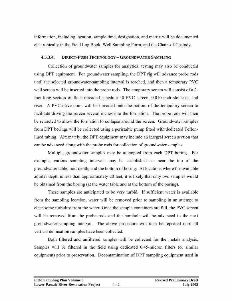
information, including location, sample time, designation, and matrix will be documented
electronically in the Field Log Book, Well Sampling Form, and the Chain-of-Custody.
4.5.3.4. DIRECT-PUSH TECHNOLOGY – GROUNDWATER SAMPLING
Collection of groundwater samples for analytical testing may also be conducted
using DPT equipment. For groundwater sampling, the DPT rig will advance probe rods
until the selected groundwater-sampling interval is reached, and then a temporary PVC
well screen will be inserted into the probe rods. The temporary screen will consist of a 2-
foot-long section of flush-threaded schedule 40 PVC screen, 0.010-inch slot size, and
riser. A PVC drive point will be threaded onto the bottom of the temporary screen to
facilitate driving the screen several inches into the formation. The probe rods will then
be retracted to allow the formation to collapse around the screen. Groundwater samples
from DPT borings will be collected using a peristaltic pump fitted with dedicated Teflon-
lined tubing. Alternately, the DPT equipment may include an integral screen section that
can be advanced along with the probe rods for collection of groundwater samples.
Multiple groundwater samples may be attempted from each DPT boring. For
example, various sampling intervals may be established as: near the top of the
groundwater table, mid-depth, and the bottom of boring. At locations where the available
aquifer depth is less than approximately 20 feet, it is likely that only two samples would
be obtained from the boring (at the water table and at the bottom of the boring).
These samples are anticipated to be very turbid. If sufficient water is available
from the sampling location, water will be removed prior to sampling in an attempt to
clear some turbidity from the water. Once the sample containers are full, the PVC screen
will be removed from the probe rods and the borehole will be advanced to the next
groundwater-sampling interval. The above procedure will then be repeated until all
vertical delineation samples have been collected.
Both filtered and unfiltered samples will be collected for the metals analysis.
Samples will be filtered in the field using dedicated 0.45-micron filters (or similar
equipment) prior to preservation. Decontamination of DPT sampling equipment used in
Field Sampling Plan Volume 3 Revised Preliminary Draft Lower Passaic River Restoration Project 4-42 July 2005

groundwater sampling will follow the decontamination procedures set forth in FSP
Volume 1 (Malcolm Pirnie, 2005a).
4.5.3.5. SURFACE WATER SAMPLING
Due to the shallow nature of most wetland areas, surface water samples will be
generally collected directly into the sample jars by dipping the containers into the water.
If necessary, long-handled stainless steel dippers may be used to collect and transfer
surface water samples to laboratory containers. Sample labels will be completed after the
jars have been filled, to minimize potential volatile contamination from the marker pens.
Latex or nitrile gloves will be worn during sample collection. Jars will be filled upstream
of where the sampling personnel are standing in the stream. For multiple samples in a
stream, collection will start at the most down-gradient location and end at the most
upgradient location, which will prevent disturbed and entrained sediments from
impacting downstream surface water sampling locations. The following in-situ readings
will be obtained after samples are collected at each surface water sampling location:
• pH;
• Dissolved oxygen;
• Specific conductance and salinity;
• Oxidation-reduction potential;
• Temperature;
• Turbidity; and
• Eh (if monitoring sonde is capable).
Surface water sampling from the main stem of the Lower Passaic River is
discussed in FSP Volume 1 (Malcolm Pirnie, 2005a) along with the collection of
particulate organic carbon, dissolved organic carbon, and nutrient data.
4.5.4. Sample Analysis and Reporting
The chemical analyses to be performed collectively for groundwater and surface
water samples include PCBs (as Aroclors and congeners), TCL volatile organic
compounds, TCL semi-volatile organic compounds (base-neutral fraction; PAHs
Field Sampling Plan Volume 3 Revised Preliminary Draft Lower Passaic River Restoration Project 4-43 July 2005

compounds only), TCL pesticides and herbicides, TAL metals, PCDDs/PCDFs, and
TOC. At each of the surface water sampling locations, field measurements will be
collected (see Section 4.5.3.5 “Surface Water Sampling”).
Post-processing, analysis, and interpretation of all field and laboratory data will
be completed prior to the completion of a Water Quality Investigation Report. Maps,
analytical data, and field measurements will be prepared and included in both the Draft
and Final Reports.
4.6. TASK 6 –HYDROLOGIC & HYDRODYNAMIC (PMP TASKS JAB AND
JFB)
This section only addresses potential hydrologic and hydrodynamic investigations
for restoration of wetland habitat and areas along the tributaries of the Lower Passaic
River. For other types of restoration opportunities at locations along the main stem of the
river, the hydrologic and hydrodynamic model developed for the contaminant fate and
transport model will be used (refer to the Draft Modeling Plan; HydroQual, 2005). Note
that although the Draft Modeling Plan does not directly address WRDA-related issues, it
is anticipated that the main issues for the Passaic River will apply to the investigation of
the candidate restoration sites. For example, the hydrodynamic models developed under
CERCLA will include: the restoration of water quality, sediments and watershed drainage
areas, and possibly nearby wetlands in the upper Newark Bay; the protection of river
biota from contact with concentrations of multiple chemicals in the river sediments to
help restore aquatic habitat; and the reduction and control of pollutants now entering the
river from storm water runoff, outfalls, and atmospheric deposition to assist with
restoration and to maintain the restored habitat.
4.6.1. Data Needs and Sampling Objectives
Except for the data summarized in Section 3.7 “Hydrology and Hydrodynamics,”
no other site-specific hydrological or hydrodynamic data were found on the internal
project database. Future hydrologic and hydrodynamic investigations are required to
support the following data needs, which address DQO questions 1, 9, and 28:
Field Sampling Plan Volume 3 Revised Preliminary Draft Lower Passaic River Restoration Project 4-44 July 2005

• Determine groundwater and surface water elevations, fluctuations, and flow
directions or regimes to understand the hydrologic and hydrodynamic factors that
may affect restoration feasibility analyses (refer to DQO task 28G).
• Define channel layout and other design parameters required for the successful
establishment of a salt or brackish wetland (refer to DQO tasks 1A, 1B, and 1C).
• Simulate the hydraulics and the water quality characteristics of the proposed wetland
system (refer to DQO tasks 1A, 1B, and 1C).
• Determine that suitable surface or subsurface hydrology exists to sustain the intended
restoration design and foundation (refer to DQO tasks 1A, 1B, 1C, and 9A).
• Provide the basis for the horticultural design and planting of the wetland (refer to
DQO task 28G).
• Provide the basis for maintaining aesthetics at a site (refer to DQO task 28G).
• Study the flooding potential in offsite areas adjacent to the restoration area (refer to
DQO task 28G).
• Provide information required for the evaluation of alternatives in the NEPA-EIS
(refer to DQO task 28L).
4.6.2. Sample Locations and Frequency
A site-specific hydrologic investigation will be determined once candidate
restoration sites are determined. It is likely that each candidate restoration site will
require the installation of three or more monitoring wells and/or piezometers, staff
gauges, and the installation of water-level data-loggers to record water level data.
4.6.3. Preliminary Hydrologic & Hydrodynamic Methods
To monitor tidal fluctuations in the unconsolidated aquifer, wetland, and stream
channels due to tidal influence in the nearby Lower Passaic River, several monitoring
methods may be implemented on a site-specific basis. These methods include the
installation of piezometers and staff or tide gauges. In addition, there could be a need to
develop a geomorphic map for use in modeling wetland and tributary hydrodynamics.
Field Sampling Plan Volume 3 Revised Preliminary Draft Lower Passaic River Restoration Project 4-45 July 2005

The following presents an overview of the prospective methods that may be implemented
during this program.
For candidate restoration sites and Lower Passaic River tributaries, a hydrologic
features map will be prepared (scale 1 inch = 100 feet) from aerial photographs that show
stream or drainage channels with areas of ponded water and/or mudflats. A set of
quantitative measurements and calculations will be prepared from this map, including:
channel classification (order); total number of channels in each order; and the calculation
of bifurcation ratio, channel frequency, total length (sinuous length), total linear length,
average channel length, channel length ratio, average channel sinuosity, and drainage
density. The methods and calculations will be based on Chow et al. (1988), Chow
(1964), and Horton (1945). A field reconnaissance will be conducted to confirm the map.
The hydrogeologic features data will be prepared in a separate layer for electronic use
(AutoCAD 2004 format).
A hydrologic-hydraulic analysis will be made of the Lower Passaic River and
adjacent contributory drainage areas based on a tidal storm comparable with existing
control measures for the surrounding community and the 100-year fluvial storm event.
This analysis will be performed with the refined Contaminant Assessment and Reduction
Program (CARP) model; however, if this water quality model cannot perform the
required simulations, then alternative models may be implemented. [Note refer to the
Draft Modeling Work Plan (HydroQual, 2005) for more information on the revised
CARP model.] Alternative models include a USACE or in-house hydrodynamic models
(e.g., LATIS; TAMS, an Earth Tech Company) and mathematical simulations to
characterize existing and proposed hydrologic and hydraulic conditions. Both of these
alternative models require the following data: salinity, temperature, water elevation,
current, meterological data, and river discharge.
The LATIS has been in use for more than 25 years in studying unsteady-state tidal
hydraulics at their restoration sites along the Hackensack River. This model is a Quasi-
2D, finite difference model used in simulation of tidal channels through wetland
restoration sites. If necessary, another USACE or in-house model (e.g., WASP5; TAMS,
Field Sampling Plan Volume 3 Revised Preliminary Draft Lower Passaic River Restoration Project 4-46 July 2005

an Earth Tech Company) may be used for water quality simulations if the water quality
model being developed by USEPA cannot perform the required simulations. A design
report will be prepared and submitted that presents the modeling assumptions and
criteria, the results of the hydrologic and hydraulic analysis, and criteria for the design of
the proposed water management facilities to meet the project’s mitigation potential,
habitat enhancement and flood protection objectives.
Installation of piezometers will follow the construction methods outlined in
Section 4.4.3.1 “Soil Sampling and Monitoring Well/Piezometer Boring Procedures.”
Groundwater elevations will be used to evaluate the hydrogeologic regime in the vicinity
of the candidate restoration site. Due to the potential for influence from tidal fluctuations
on the unconfined aquifer, a staff gauge with a self recording tide gauge connected to a
submerged atmospheric compensated transducer will be installed in the river to obtain
river stage elevations. These staff gauge readings will then be compared with
groundwater elevations from the piezometers fitted with similar self-recording pressure
transducers to quantify tidal effects at the restoration site. A staff gauge will be installed
adjacent to each restoration site to identify and/or confirm tidal fluctuations.
4.6.4. Hydrologic & Hydrodynamic Reporting
Post-processing, analysis, and interpretation of all field data will be completed
prior to the completion of a Hydrologic & Hydrodynamic Report. Hydrologic and
geomorphic maps, field measurements, and modeling results will be prepared and
included in both the Draft and Final Reports.
4.7. TASK 7 – CULTURAL RESOURCES (PMP TASK JG)
The cultural resource investigations will be conducted on candidate restoration
sites as well as within the main stem of the Lower Passaic River. Section 106 of the
National Historic Preservation Act of 1966 (as amended) requires Federal agencies, or
project sponsors, seeking Federal funding and/or permits to take into account the effect of
any undertaking on any cultural resource included in, or eligible for inclusion in, the
National Register of Historic Places (NRHP). As a Federal agency the USACE is
Field Sampling Plan Volume 3 Revised Preliminary Draft Lower Passaic River Restoration Project 4-47 July 2005

responsible for the identification, protection and preservation of significant cultural
resources within the Area of Potential Effect (APE) of any proposed project. (The APE
refers to the boundaries of the project where cultural resources could be impacted. The
APE boundaries are determined by identifying direct physical impacts to resources such
as digging and demolition of building, secondary impacts like access roads for
construction, long term impacts like inundation and root penetration from new plantings,
and visual impacts including unsightly elements of the constructed project that could
undermine a historic landscape.) Significant cultural resources are any material remains
of human activity that are listed on, or eligible for inclusion on the NRHP. Other statutes
and regulations authorizing the USACE to undertake these responsibilities include
Section 101 (b) (4) of the National Environmental Policy Act of 1969 and the Advisory
Council Procedures for the Protection of Cultural Properties (36 CFR Part 800).
4.7.1. Data Needs and Study Objectives
Cultural resource investigations will be conducted to identify potentially
significant resources on or near candidate restoration sites and within the main stem of
the Lower Passaic River. Cultural resource investigations will also evaluate their
eligibility for inclusion on the National Register of Historic Places. These investigations
are required to support the following DQO tasks: 6A, 22B, and 28H.
Restoration planners will then be able to evaluate how to best avoid or minimize
any impacts to eligible resources. An evaluation of the impact of alternative plans on
eligible properties will be developed as part of the cultural resources investigation in
consultation with the New Jersey SHPO. If eligible resources cannot be avoided, a
Memorandum of Agreement (MOA) will be developed in consultation with the New
Jersey SHPO to mitigate for unavoidable impacts. Any work stipulated in the MOA will
be undertaken prior to initiation of project construction unless otherwise agreed with the
New Jersey SHPO.
Field Sampling Plan Volume 3 Revised Preliminary Draft Lower Passaic River Restoration Project 4-48 July 2005

4.7.2. Preliminary Cultural Resource Methods
Cultural resources identified during the initial phase of the survey (Phase 1A,
Phase 1) as potentially eligible for inclusion on the NRHP that are within the APE will be
investigated further (Phase II and III) through additional research and fieldwork.
Fieldwork may entail subsurface testing, geomorphological sampling, and remote
sensing. The fieldwork will be tailored to each restoration alternative proposed and will
be based on site topography, fill depths, anticipated resources, and proposed project
actions. At this phase, if resources are identified, their eligibility for listing on the NRHP
will be evaluated. Recommendations will be made for avoiding significant sites and
possible mitigation measures will be suggested, if sites cannot be avoided. A
Memorandum of Agreement may need to be developed in consultation with the New
Jersey SHPO to mitigate for adverse effects. Topographic maps with preliminary project
designs will be needed before a scope of work for cultural resource work can be
developed. Cultural resource considerations that may influence the selected plan will be
summarized and clearly set forth in the FS report and in the candidate restoration site
design documents.
Remediation may include sediment removal, capping, and decontamination and
restoration goals may include benthic habitat restoration, tidal wetland restoration,
vegetative buffer creation, shoreline stabilization, and aquatic habitat improvement.
Multiple types of cultural resource survey and archeological recovery techniques will be
employed in order to investigate in wet, dry, and tidal environments. For dry upland
areas, conventional archaeological techniques will be employed including ground
reconnaissance, test pitting and trench or unit excavations. A ground reconnaissance
survey of the area will be conducted to identify any extant historic structures or
anomalous features along the ground indicating buried remains that could be impacted by
the project. The ground reconnaissance and a review of historic maps will provide
guidance for the subsurface testing portion of the survey. If the reconnaissance and map
documentation indicate the likelihood for buried cultural resources, a testing plan will be
developed based on the nature of the project in each area. Cultural resources that are
Field Sampling Plan Volume 3 Revised Preliminary Draft Lower Passaic River Restoration Project 4-49 July 2005

potentially threatened by the project will be reviewed by the project team and the New
Jersey SHPO, and through coordination with the New Jersey SHPO, a mitigation plan
will be developed, depending on the nature and level of the impact that is anticipated.
Archaeological resources that will be completely demolished or destroyed could be fully
excavated or thoroughly documented prior to construction. Some extant structures could
be relocated or the project plans could be altered to avoid impacting the resource.
To identify sub-aquatic or sub-bottom prehistoric resources, documentary
research will be conducted, which focuses on existing geomorphological studies of the
area to determine locations that are potentially sensitive for prehistoric resources. Side-
scan sonar and sub-bottom profiling survey data can be used to identify buried and
submerged landforms, such as old river valleys, which might have been attractive to
prehistoric cultures. The data obtained from sub-bottom profiling surveys might also
indicate whether any such landforms were associated with preserved geologic strata
containing land surfaces, which might have been available for human occupation.
In the event that potential prehistoric land surfaces were identified, additional
information about their age and ecology could be obtained through sedimentary coring as
part of the site-specific data collection for geotechnical purposes. As traditional
archaeological data recovery is not feasible in these deeply submerged conditions, a
coring program and subsequent analysis of the recovered columns may be used as
mitigative measures to compensate for any adverse effects to prehistoric resources.
Study of cores could include grain-size, pollen, foraminifera and geochemical analyses.
The cores can also be used to assess the potential utility of more intensive sampling and
data recovery of those locations. If adopted as a mitigative measure, a coring program
could obviate the need for additional work or the avoidance of those areas in the siting of
a restoration area.
To identify historic resources documentary research will be conducted. This work
will focus on several existing surveys of shipwrecks on the East Coast, and in the North
Reach of Newark Bay. Primary sources such as Maritime Registers and Life-Saving
Service records may be consulted. Remote sensing techniques can be used to identify the
Field Sampling Plan Volume 3 Revised Preliminary Draft Lower Passaic River Restoration Project 4-50 July 2005

locations of shipwrecks or other isolated artifacts lost or dumped in the Passaic River and
Newark Bay. The side-scan sonar and sub-bottom profiling survey data collected for
prehistoric landforms can also be used to identify buried historic structures and vessels.
Once restoration sites are determined, a magnetometer survey of these more defined areas
can be undertaken. Remote sensing targets can then be evaluated for potential
significance based on their type, size, appearance and correlation with historic data.
Recommendations can be made at that time as to the potential eligibility of the target and
as to the need for further investigations. Diving on the target by a qualified underwater
archaeologist may be necessary to identify the nature of the target and determine its
significance. If no historic properties are identified in the area of potential effect, then
depending on SHPO review, no further cultural resources investigations would be
required. If historic properties are present, then the potential impacts of the alternatives
on eligible sites will be identified and alternatives for avoidance or impact minimization
will be developed. Mitigation for unavoidable adverse impacts could entail a variety of
alternatives based on the type of resource and may include such measures as detailed
recording of a structure or vessel, detailed documentary research or conservation of
selected elements of the resource.
To identify near shore resources, documentary research and a review of historic
maps, including an evaluation of historic landfilling and dredging activities in the project
area, will be undertaken. Research will be followed by a survey of the property on foot
or by boat. This survey will determine the presence of historic structures and landscapes.
A preliminary assessment of archaeological potential will be undertaken which will be
based primarily on existing maps and coring data. This preliminary work will determine
the need for further cultural resources studies. If necessary, a program of borings may
have to be conducted to determine the presence or absence of potential archaeological
deposits. If project activities are proposed on-shore, excavations by mechanical means,
such as a backhoe, may be required. Further studies may be needed to assess the
eligibility of identified architectural or archaeological resources. If no eligible resources
are identified in the area of potential effect then, depending on SHPO review, no further
Field Sampling Plan Volume 3 Revised Preliminary Draft Lower Passaic River Restoration Project 4-51 July 2005

cultural resources investigations would be required. If historic properties are present the
potential impacts of the alternatives on eligible sites will be identified and alternatives for
avoidance or mitigation will be developed. Mitigation can entail a variety of alternatives
based on the type of resource and may include such measures as detailed recording of a
structure or vessel, detailed documentary research, conservation of selected elements of
the resource or detailed archaeological investigations. Avoidance of resources eligible
for the NRHP is recommended but particularly for submerged resources where the costs
associated with documenting sites and recovering, conserving, maintaining and storing
artifacts can be high.
4.7.3. Cultural Resource Reporting
Interim, draft, and final reports will be prepared by the USACE or the contractor.
The report produced by a cultural resource investigation is of potential value not only for
its specific recommendations, but also as a reference document. To this end, the report
can be used as a basis for any future cultural resources work, and will meet both the
requirements for cultural resource protection and scientific standards of current research
as defined in 36 CFR Part 800 and the Councils Handbook and the Advisory Council on
Historic Preservation’s Handbook.
4.8. TASK 8 – SOCIOECONOMICS (PMP TASK JB)
The objective of socioeconomic analyses is to measure the cost effectiveness,
social fairness, and institutional implementability of each restoration plan proposed for
the contaminated environmental media in the Lower Passaic River and the candidate
restoration sites. The restoration plans to be evaluated are expected to address the
CERCLA objectives of removal of site contaminants or remediation of contaminated
sediments and the FS objective of environmental restoration for candidate restoration
sites. The study period for all evaluations will be 50-years to be consistent with the FS
requirements.
Field Sampling Plan Volume 3 Revised Preliminary Draft Lower Passaic River Restoration Project 4-52 July 2005

4.8.1. Data Needs and Objectives
The objective of the socioeconomic analysis is to assess and prioritize proposed
restoration alternatives according to the criteria described above to support decision-
making. The socioeconomic investigation is required to support the following DQO
questions: 28 and 29.
• Habitat units for each alternative from Project Management Plan: Task JDE:
Environmental Resource Inventory Report (USACE et al., 2003) by project feature
(refer to DQO tasks 28I and 29C).
• “Report of Channel Conditions: For Channels 400 Feet Wide or Greater” (Engineer
Form 4020) documenting channel conditions since initial construction (refer to DQO
tasks 28I and 29C).
• Dredging sounding maps of Lower Passaic River for times and projects determined
after reviewing “Report of Channel Conditions: For Channels 400 Feet Wide or
Greater” Engineering Form 4020-R (USACE, 1990c) data (refer to DQO tasks 28I
and 29C).
• Historic dredging costs since last significant project deepening (refer to DQO tasks
28I and 29C).
• Property values adjacent to environmentally restored shorelines (refer to DQO tasks
28I and 29C).
• Demographic data (refer to DQO tasks 28I and 29C).
• Project cost estimates, including operation and maintenance, project cost outlay
schedule by project feature, project implementation schedule, financing plan, and
statement of financial capability (refer to DQO tasks 28I and 29C).
4.8.2. Preliminary Socioeconomic Methods
4.8.2.1. ECONOMIC ANALYSIS
Remediation or restoration plans will have two types of benefits: Those that can
be quantified in terms of monetary value and ecological benefits. The latter type will be
developed in “Task JDE: Environmental Resource Inventory Report” (Project
Field Sampling Plan Volume 3 Revised Preliminary Draft Lower Passaic River Restoration Project 4-53 July 2005

Management Plan; USACE et al., 2003). Estimating only those benefits with monetary
value is within this scope.
For CERCLA plans, Implementation Guidance (CECW-P/CECW-O
memorandum dated April 25, 2001, Subject: Implementation Guidance for Section 312
of the Water Resources Development Act of 1990, Environmental Dredging, as amended
by Section 224 of the Water Resources Development Act of 1999) limits the monetary
benefits to operations and maintenance cost savings. Note that most of the anticipated
saving would actually occur at the New York and New Jersey Federal Navigation
Channels. The non-monetary benefits from “Task JDE: Environmental Resource
Inventory Report” are also included. Quantifying operation and maintenance cost
savings will require extensive coordination with the USACE-New York District. The
District will provide historic dredging costs, each Engineer Form 4020 (“Report of
Channel Conditions: For Channels 400 Feet Wide or Greater”) documenting channel
conditions, and pre- and post-dredging sounding maps. The most promising potential
monetary benefit may be eliminating the need for upland disposal of contaminated
sediments and allowing open-water disposal or upland beneficial use placement options.
For FS plans, the only benefits (usually termed “outputs”) are again non-monetary
benefits from “Task JDE: Environmental Resource Inventory Report”. However, other
monetary benefits can be used to offset costs in the analysis. Such monetary benefits or
cost offsets typically include the value of recreation provided, but are not limited by type.
As this study area is intensely developed, it is expected that cost offsets may include the
anticipated increase in property values adjacent to environmentally restored shorelines.
“Planning Guidance Notebook” Engineering Release Form (ER) 1105-2-100 (USACE,
2000) provides the guidance followed in FS.
Recreation benefits depend on the amount of increased recreation activity and the
value of the recreation activities. The value will be based on either unit day values or
contingent values, depending on the level of increase. Contingent values would likely
require surveys of likely users. Unit day values are usually combined with capacity
estimates, while the contingent valuation method provides a basis for estimating demand.
Field Sampling Plan Volume 3 Revised Preliminary Draft Lower Passaic River Restoration Project 4-54 July 2005

The analysis of environmental restoration projects uses Cost Efficiency and Incremental
Cost Analysis (CE/ICA). This will be accomplished using the Institute of Water
Resources (IWR) PLAN Decision Support Software. The CE/ICA will require six steps.
• Step 1. Display outputs and costs. Calculate average annual outputs (not discounted)
and equivalent annual costs (discounted) based on inputs from the planning team over
the 50-year planning horizon. Net Ecosystem Restoration (NER) costs will include
operation and maintenance, and interest during construction. The NER costs are
reduced by offsetting monetary benefits.
• Step 2. Identify combinable management measures. In this step, planners formulate
all possible combinations of management measures and scales.
• Step 3. Calculate outputs and costs of combinations. All possible combinations of
management measures and scales are sorted in terms of output. This provides the
basis for developing a supply curve.
• Step 4. Conduct cost effectiveness analysis. A plan is cost effective if no other plan
provides the same level of output for less cost and if no other plan provides more
output for the same or less cost. This step identifies the best solution for a given
amount (or range) of outputs. This essentially creates a supply curve and eliminates
economically ineffective solutions.
• Step 5. Incremental cost analysis. Incremental cost analysis identifies the subset of
cost effective plans that are superior financial investments, called “best buys.” Best
buys are the most efficient plans at producing the output variable. They provide the
greatest increase in the value of the output variable for the least increase in cost. The
first best buy plan is the most efficient plan, producing output at the lowest
incremental cost per unit. If a higher level of output is desired than that provided by
the first best-buy plan, the second best buy plan is the most efficient plan for
producing additional output, and so on. That is the same as identifying the plans with
the lowest incremental cost per habitat unit. This is a marginal cost analysis. This
step considers the most cost effective plans by scale of output, beginning with the
Existing Condition.
Field Sampling Plan Volume 3 Revised Preliminary Draft Lower Passaic River Restoration Project 4-55 July 2005

• Step 6. Recalculate incremental costs. This step uses iterative incremental cost
analysis to identify plans where there is a significant change in incremental costs and
identify the potential NER plans. This step first looks at the incremental costs and
outputs for plans larger than the first “Best Buy” plan. This step continues to
iteratively consider only plans larger (i.e. providing more output) than the last best
buy plan with the incremental costs and outputs relative to that last plan. This process
continues until the plan formulated to provide the most outputs is identified as a best
buy.
4.8.2.2. SOCIAL STUDIES
The existing social, economic, and demographic characteristics of study area
populations will be documented. The 2000 census data are expected to be the basis for
most of this information. These characteristics can be obtained by community and by
block group level from the U.S. Census Bureau website (www.census.gov). Block group
data will be aggregated for areas of interest, such as by reach.
Social impacts to consider include: income distribution; employment distribution;
population distribution and composition; the fiscal condition of the state and local
governments; the quality of community life; life, health, and safety factors; displacement;
long-term productivity; and energy requirements and energy conservation.
The measurement of social impacts requires projections into the future with and without
the project. Projections will be coordinated with County government or, more typically,
with the local Council of Governments. Human Health and Ecological risk assessments
will be carried out by the USEPA as part of “Task JFB: HTRW Site Inspection and
Sediment Characterization Report.” The social analysis of impacts will also make use of
information gathered as part of the public involvement program.
Environmental Justice Criteria include the concept of an appropriate comparison
group. The social analysis can be used to help define an appropriate comparison group.
Environmental Justice Issues can arise from the choice of area to remediate, restore, or
used for treatment or confinement.
Field Sampling Plan Volume 3 Revised Preliminary Draft Lower Passaic River Restoration Project 4-56 July 2005

4.8.2.3. INSTITUTIONAL STUDIES
The institutional analysis will consider the constraints and opportunities in
implementing proposed restoration efforts. Unlike environmental sample analytical
results and demographics, the data gathered will be legal and institutional information
frequently not quantified with numerical values.
The institutional analysis will identify relevant government jurisdictions and
interview appropriate contacts to identify relevant legal requirements. A practicing
attorney will review the requirements and prepare a summary addressing their potential
effects on remediation and restoration plan formulation.
Cost sharing formulation among potentially responsible parties (PRPs) may be
problematic. For instance, some PRPs might enter bankruptcy proceedings. The
institutional analysis will assess the certainty of funds from PRPs and other sources. An
example framework will be developed for the commitment of funding from the PRPs on
a timely basis. The example framework will also incorporate reasonable opportunities
for the PRPs to review the progress of plan implementation. This framework will specify
a method for dealing with cost variances and scheduling changes. It will also provide a
mechanism for the escrow of funds. Provision will be made to allow for public review
and comment on the broad outline of the framework.
While there are multiple possible non-Federal sponsors for the construction phase,
non-governmental organization (NGO) funding will also be considered. (Note that the
non-federal sponsors have not been identified yet.) For example, the Passaic River
Coalition has indicated a willingness to provide funding or assets for selected projects.
The institutional analysis will work to take advantage of such opportunities while
evaluating the responsibility for perpetual operation and maintenance of any alternatives
recommended for implementation.
The institutional analysis is considered to be an ongoing effort intended to
facilitate achievement of environmental and socioeconomic goals that might otherwise be
compromised by the self-interest of groups and institutions.
Field Sampling Plan Volume 3 Revised Preliminary Draft Lower Passaic River Restoration Project 4-57 July 2005

4.8.2.4. ABILITY TO PAY
The cost sharing for Flood Control projects can be adjusted to reflect limitations
on the ability of some communities to pay. As this project is not expected to include
flood control, this activity will not be undertaken.
4.8.2.5. FINANCIAL ANALYSIS
The requirements for a conducting a Financial Analysis are contained in
Appendix D of “Planning Guidance Notebook” ER 1105-2-100 (USACE, 2000). The
local sponsor will provide a Financing Plan based on comprehensive cost estimates and a
Statement of Financial Capability. The Financial Analysis Report will draft the District
Commander’s assessment of the non-Federal sponsor’s financial capability.
4.8.3. Socioeconomic Reporting
Reporting for this task will include identification of a recommended restoration
alternative, based on the output of the analyses described above, and a prioritized listing
of the possible alternatives in decreasing order of socioeconomic effectiveness. The
affects of these alternatives on Environmental Justice will be displayed. The institutional
and financial implementability of these alternatives will be assessed.
Documentation will be provided regarding the various inputs to the
socioeconomic model for each alternative, along with a discussion of potential
uncertainties in the model input and their impacts on the prioritization of the alternatives.
4.9. TASK 9 - REAL ESTATE (PMP TASK JC)
According to “Real Estate Handbook” ER 405-1-12 (USACE, 1985), a Real
Estate Plan (REP) is the real estate work product that supports project plan formulation.
It identifies and describes the lands, easements, and rights-of-way (LER) required for the
construction, operation, and maintenance of a proposed project, including those required
for relocations, borrow material and dredged or excavated material disposal.
Field Sampling Plan Volume 3 Revised Preliminary Draft Lower Passaic River Restoration Project 4-58 July 2005
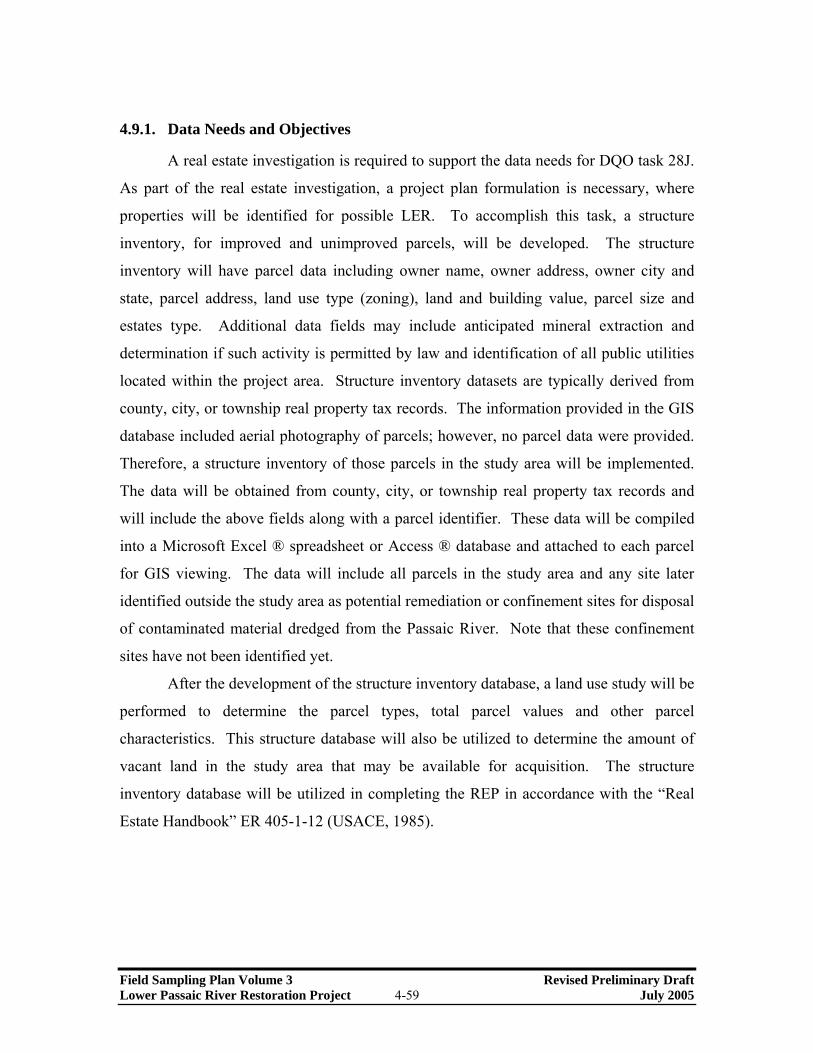
4.9.1. Data Needs and Objectives
A real estate investigation is required to support the data needs for DQO task 28J.
As part of the real estate investigation, a project plan formulation is necessary, where
properties will be identified for possible LER. To accomplish this task, a structure
inventory, for improved and unimproved parcels, will be developed. The structure
inventory will have parcel data including owner name, owner address, owner city and
state, parcel address, land use type (zoning), land and building value, parcel size and
estates type. Additional data fields may include anticipated mineral extraction and
determination if such activity is permitted by law and identification of all public utilities
located within the project area. Structure inventory datasets are typically derived from
county, city, or township real property tax records. The information provided in the GIS
database included aerial photography of parcels; however, no parcel data were provided.
Therefore, a structure inventory of those parcels in the study area will be implemented.
The data will be obtained from county, city, or township real property tax records and
will include the above fields along with a parcel identifier. These data will be compiled
into a Microsoft Excel ® spreadsheet or Access ® database and attached to each parcel
for GIS viewing. The data will include all parcels in the study area and any site later
identified outside the study area as potential remediation or confinement sites for disposal
of contaminated material dredged from the Passaic River. Note that these confinement
sites have not been identified yet.
After the development of the structure inventory database, a land use study will be
performed to determine the parcel types, total parcel values and other parcel
characteristics. This structure database will also be utilized to determine the amount of
vacant land in the study area that may be available for acquisition. The structure
inventory database will be utilized in completing the REP in accordance with the “Real
Estate Handbook” ER 405-1-12 (USACE, 1985).
Field Sampling Plan Volume 3 Revised Preliminary Draft Lower Passaic River Restoration Project 4-59 July 2005

4.9.2. Preliminary Real Estate Methods
4.9.2.1. GROSS APPRAISAL/REPORT
According to the Project Management Plan (USACE et al., 2003), the USACE
New York District’s Real Estate Division will evaluate the selected ecosystem restoration
project and conduct a Gross Appraisal, which includes the preparation of a Baseline Cost
Estimate For Real Estate in the Micro Computer-Aided Cost Engineering System
(MCACES) format and a Real Estate Supplement. The Baseline Cost Estimate for a
project is the estimated total costs to implement the project. It includes estimated costs
for the costs for lands, easements, rights-of-way, relocations and disposal areas
(LERRD), planning and design, construction management, construction, contingencies,
etc. Civil Tech Engineering, Inc. (Houston, Texas) will compile these costs for input into
MCACES in accordance with “USACE Business Process” ER 5-1-11 (USACE, 2001b),
“Accounting and Reporting Civil Works Activities CH 1-89” ER 37-2-10 (USACE,
2004b), “Civil Works Cost Engineering” ER 1110-2-1302 (USACE, 1994), and the Civil
Works, Work Breakdown Structure (WBS).
4.9.2.2. PRELIMINARY REAL ESTATE ACQUISITION MAPS
According to the Project Management Plan (USACE et al., 2003), the USACE
New York District’s Real Estate Division, in conjunction with its Engineering and
Planning Divisions, will perform this task.
4.9.2.3. PHYSICAL TAKINGS ANALYSIS
This task includes a discussion of whether there will be flooding induced by
construction operation and maintenance of the project. If induced flooding is anticipated,
then the REP will also describe the nature and extent thereof and whether additional LER
will be acquired as a result. Where significant induced flooding anticipated, or where
otherwise required, a written Physical Taking analysis separate from the REP will be
prepared with the conclusion of the analysis included in the REP. The information will
be obtained from the structure inventory database and will be include the owner’s name,
Field Sampling Plan Volume 3 Revised Preliminary Draft Lower Passaic River Restoration Project 4-60 July 2005

address, size of parcel and estate. This is to comply with the “Real Estate Handbook” ER
405-1-12 (USACE, 1985).
4.9.2.4. PRELIMINARY ATTORNEY’S OPINION OF COMPENSABILITY
Due to the legal nature of this task, it is understood that the USACE New York
District is responsible for this task.
4.9.2.5. RIGHTS OF ENTRY
Documents which evidence permission from the landowner to temporarily use
owner(s) lands for a specific time and purpose will be obtained for the purpose of
environmental investigations, cultural assessments, core sampling, surveys, explorations,
etc. Government, Contractor or the non-Federal Sponsor may obtain the Rights-of-Entry
(ROE). The “Department of the Army Right-of-Entry for Survey and Exploration”
Engineering Form 1258-R; (USACE, 1998) will be used by the District to obtain Rights-
of-Entry.
4.9.2.6. OTHER REAL ESTATE DOCUMENTS / EXTERNAL TECHNICAL REVIEW
Civil Tech Engineering will perform this task in accordance with the “Real Estate
Handbook” (ER405-1-12; USACE, 1985) and will include the following additions to the
REP.
• A discussion of any relocation assistance benefits anticipated being required in
accordance with the Uniform Relocation Assistance Act (PL 91-646), including the
number of persons, farms and businesses to be displaced and estimated costs. It will
describe the availability of replacement housing and the need for last resort housing
benefits, if required.
• A discussion of the present or anticipated mineral activity in the vicinity of the
proposed project that may affect construction, operation, maintenance of the project
together with a recommendation, including rationale, regarding acquisition of mineral
rights or interests. The REP will also discuss other subsurface minerals or timber
activity if applicable.
Field Sampling Plan Volume 3 Revised Preliminary Draft Lower Passaic River Restoration Project 4-61 July 2005

• A thorough assessment of the non-Federal sponsor's legal and professional capability
and experience to acquire and provide the LER for the construction, operation and
maintenance of the project, including condemnation authority and quick-take
capability. The REP will indicate whether the non-Federal sponsor was advised of
the Uniform Relocation Assistance requirements and the requirements for
documenting expenses for credit purposes. An Assessment of Non-Federal Sponsor’s
Real Estate Acquisition Capability checklist will be prepared as required by Project
Guidance Memorandum Letter No 12, dated May 2, 1996.
• A discussion of the type of ordinance proposed, its intended purpose, and whether
enactment and enforcement of the ordinance will result in a taking of a real property
interest for which compensation will be paid, if enactment of zoning ordinances is
proposed in connection with the project.
• A reasonably detailed schedule of all land acquisition milestones, including LER
certification. Real Estate, the Project Manager, and the sponsor will agree upon the
dates reflected in the schedule.
• A concise discussion of the impacts on the real estate acquisition process (e.g. values,
schedules) due to known or suspected presence of contaminants that are located in,
on, under, or adjacent to the LER required for the construction, operation or
maintenance of the project including LER that is subject to the navigation servitude.
The discussion will include the status of the District’s and USEPA’s investigation for
such contaminants, whether such contaminants are regulated under CERCLA, other
Federal statutes [e.g. Resource Conservation and Recovery Act (RCRA)] or specified
state law. The REP will also disclose whether clean up, or other response action will
be required to implement the project, and who will be responsible for performing, and
paying the costs of performing such work as between the Government and the
sponsor.
• A discussion of known or anticipated support for, or opposition to, the project by
landowners in the project area and any known or anticipated landowner concerns
Field Sampling Plan Volume 3 Revised Preliminary Draft Lower Passaic River Restoration Project 4-62 July 2005

related to issues that could impact the acquisition process (e.g. estate selection,
amount of acreage, etc.).
• A statement that the non-Federal sponsor has been notified in writing about the risks
associated with acquiring land before the execution of the Project Cooperation
Agreement.
• A description of any other real estate issue relevant to planning, designing or
implementing the project.
In addition to the foregoing, these tasks also will require:
• External technical review and response to Project Guidance Memorandum, Formal
Review Conference, or other comments.
• Adherence to Corps of Engineers Financial Management System funding
requirements and Real Estate Management Information System (REMIS)
management information systems requirements.
Field Sampling Plan Volume 3 Revised Preliminary Draft Lower Passaic River Restoration Project 4-63 July 2005

5.0 ACRONYMS
‰ per mil, or part per thousand
°C degree Celsius
σt density (units of g/mL) – 1] × 1000
ADCP Acoustic Doppler Current Profiler
AOC Administrative Order on Consent
APE Area of Potential Effect
ASCII American Standard Code for Information Interchange
ASI Automation System Interconnect, Inc.
ASPRS American Society for Photogrammetry and Remote Sensing
ASTM American Society for Testing and Materials
CADD Computer Aided Design and Drafting
CD-ROM Compact Disc, Read-Only Memory
CE/ICA Cost Efficiency and Incremental Coast Analysis
CERCLA Comprehensive Environmental Response, Compensation,
and Liability Act
CFR Code of Federal Regulations
CLP Contract Laboratory Program
CSM Conceptual Site Model
CSO Combined Sewer Overflow
DDT Dichlorodiphenyltrichloroethane
DEM Digital Elevation Model
DPT Direct Push Technology
DSCC Diamond Shamrock Chemical Company
DTM Digital Terrain Model
EIS Environmental Impact Statement
EM Engineering Manual
ER Engineering Release Form
Field Sampling Plan Volume 3 Revised Preliminary Draft Lower Passaic River Restoration Project 5-1 June 2005
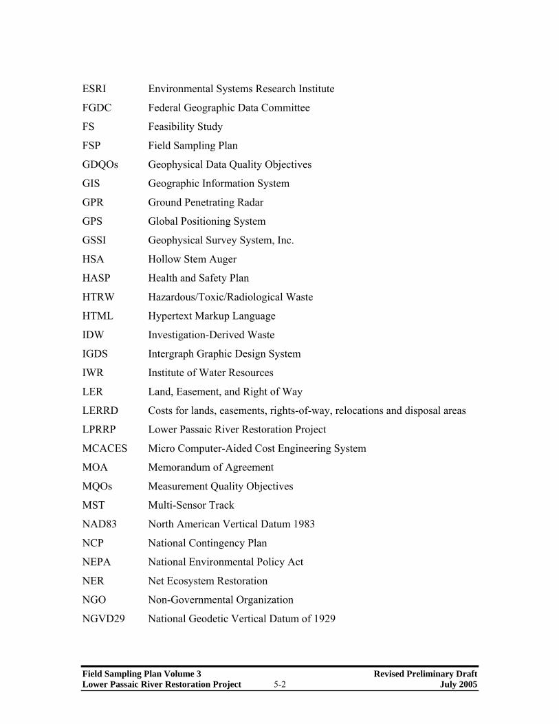
ESRI Environmental Systems Research Institute
FGDC Federal Geographic Data Committee
FS Feasibility Study
FSP Field Sampling Plan
GDQOs Geophysical Data Quality Objectives
GIS Geographic Information System
GPR Ground Penetrating Radar
GPS Global Positioning System
GSSI Geophysical Survey System, Inc.
HSA Hollow Stem Auger
HASP Health and Safety Plan
HTRW Hazardous/Toxic/Radiological Waste
HTML Hypertext Markup Language
IDW Investigation-Derived Waste
IGDS Intergraph Graphic Design System
IWR Institute of Water Resources
LER Land, Easement, and Right of Way
LERRD Costs for lands, easements, rights-of-way, relocations and disposal areas
LPRRP Lower Passaic River Restoration Project
MCACES Micro Computer-Aided Cost Engineering System
MOA Memorandum of Agreement
MQOs Measurement Quality Objectives
MST Multi-Sensor Track
NAD83 North American Vertical Datum 1983
NCP National Contingency Plan
NEPA National Environmental Policy Act
NER Net Ecosystem Restoration
NGO Non-Governmental Organization
NGVD29 National Geodetic Vertical Datum of 1929
Field Sampling Plan Volume 3 Revised Preliminary Draft Lower Passaic River Restoration Project 5-2 July 2005

NIOSH National Institute for Occupational Safety and Health
NJDEP New Jersey Department of Environmental Protection
NJDOT-OMR New Jersey Department of Transportation – Office of Maritime Resources
NOAA National Oceanic and Atmospheric Administration
NRDA Natural Resource Damage Assessment
NRHP National Register of Historic Places
NTU Nephelometric Turbidity Units
OSHA Occupational Safety and Health Administration
PAHs polycyclic aromatic hydrocarbons
PCBs polychlorinated biphenyls
PCDD polychlorinated dibenzodioxin
PCDF polychlorinated dibenzofuran
PMP Project Management Plan
PRP Potentially Responsible Parties
PVC polyvinyl chloride
QAPP Quality Assurance Project Plan
QC/QA Quality Control and Quality Assurance
RCRA Resource Conservation Recovery Act
REMIS Real Estate Management Information System
REP Real Estate Plan
RM River Mile
ROE Right of Entry
RTK DGPS Real-Time Kinematic Differential Global Positioning System
SDSFIE Spatial Data Standards for Facilities, Infrastructure, and Environment
SEG-Y A tape format standard of the Society of Exploration Geophysicists
SHPO State Historic Preservation Officer
SOP Standard Operating Procedure
SPT Standard Penetration Test
TAL Target Analyte List
Field Sampling Plan Volume 3 Revised Preliminary Draft Lower Passaic River Restoration Project 5-3 July 2005

TCL Target Compound List
TCDD 2,3,7,8-tetrachlorodibenzo-p-dioxin
TIN Triangulated Irregular Network
TOC Total Organic Carbon
TSI Tierra Solutions, Inc.
TSS Total Suspended Solids
USACE U.S. Army Corps of Engineers
USCG U.S. Coast Guard
USCS Unified Soil Classification System
USEPA U.S. Environmental Protection Agency
USFWS U.S. Fish and Wildlife Services
USGS U.S. Geological Survey
USNMAS U.S. National Map Accuracy Standards
XTF Extended Triton Format
WBS Work Breakdown Structure
WRDA Water Resource Development Act
Field Sampling Plan Volume 3 Revised Preliminary Draft Lower Passaic River Restoration Project 5-4 July 2005

6.0 REFERENCES
ASPRS, 1990. “ASPRS Accuracy Standards for Large Scale Maps.”
ASTM, 2004. Standard Specification for Portland Cement. ASTM C150-04. 20042.
ASTM, 2002. Standard Test Method for Particle-Size Analysis of Soils. ASTM D422-02.
2002.
ASTM, 2000a. Standard Practice for Soil Investigation and Sampling by Auger Borings.
ASTM D1452-80. January 2000.
ASTM, 2000b. Standard Practice for Thin-Walled Tube Sampling of Soils for
Geotechnical Purposes. ASTM D1587-00. August 2000.
ASTM, 2000c. Standard Test Method for Turbidity of Water. ASTM D-1889-00. 2000.
ASTM, 1999. Standard Test Method for Penetration Test and Split-Barrel Sampling of
Soils. ASTM D1586-99. January 1999.
ASTM, 1984. Standard Practice for Description and Identification of Soils (Visual-
Manual Procedure). ASTM D2488-84.
Caufield, DD, August, 2001. Absorption Estimation in Marine Sub-bottom Layers
Summary – An overview of the Historical Database and Typical Processed Records.
SEA Technology.
Field Sampling Plan Volume 3 Revised Preliminary Draft Lower Passaic River Restoration Project 6-1 June 2005

Caufield, DD, August, 2000. “Survey and Analysis Procedures for the Detection of
PCB’s in Marine Sediments”. Report No. 3075, Caulfield Engineering Services, Ocean
Data Equipment Corporation.
Chow, Ven Te, et al., 1988. Applied Hydrology. McGraw-Hill Book Company, New
York.
Chow, Ven Te, and Ed, 1964. Handbook of Applied Hydrology. McGraw-Hill Book
Company, New York. (Strahler, Arthur N. Section 4-II, Geology, Part II. Quantitative
Geomorphology of Drainage Basins and Channel Networks).
DSCC, 1986. Site Evaluation Addendum 80 &120 Lister Avenue. February 1986.
DSCC, 1985a Site Evaluation 80 Lister Avenue. February 1985.
DSCC, 1985b Site Evaluation 120 Lister Avenue. May 1985.
Horton, RE, 1945. Erosional development of streams and their drainage basins;
hydrophysical approach to quantitative morphology. In Bulletin of The Geological
Society of America, Volume 56, Number 3.
HydroQual, 2005. “Draft Modeling Plan.” Prepared by HydroQual under contract to
Malcolm Pirnie, Inc. (White Plains, NY) for the USEPA Region 2 and USACE-New
York District. April 2005.
Malcolm Pirnie, 2005a. “Draft Field Sampling Plan, Volume 1.” Lower Passaic River
Restoration Project. Prepared in conjunction with Battelle and HydroQual, Inc. April
2005. DACW41-02-D-0003
Field Sampling Plan Volume 3 Revised Preliminary Draft Lower Passaic River Restoration Project 6-2 July 2005

Malcolm Pirnie, 2005b. “Draft Work Plan.” Lower Passaic River Restoration Project.
Prepared in conjunction with Battelle and HydroQual, Inc. April 2005. DACW41-02-D-
0003
Malcolm Pirnie, 2005c. “Health and Safety Plan.” Lower Passaic River Restoration
Project. January 2005. DACW41-02-D-0003
Malcolm Pirnie, 2005d. “Quality Assurance Project Plan” Lower Passaic River
Restoration Project. Prepared in conjunction with Battelle and Hydroqual, Inc. April
2005. DACW41-02-D-0003
Malcolm Pirnie, 2005e. “Draft Technical Memorandum: Preliminary Geochemical
Evaluation.” Lower Passaic River Restoration Project. April 2005. DACW41-02-D-0003
McGee, RG and RF Ballard, 1995. A Technique to Assess the Characteristics of Bottom
and Sub-bottom Marine Sediments. USACE Waterways Experiment Station, Technical
Report DRP-95-3.
NOAA, 1999. Technical Memorandum. Passaic River Study Area Sampling Station-
Bivalve Mussel Deployment August 5, 1999 and Weekly Bivalve Deployment Check,
August 10, 1999. October 22, 1999.
NOAA, 1972. Tide Tables, High and Low Water Prediction, East Coast of North
American and South America Including Greenland, U.S. Dept. of Commerce, National
Oceanic Survey, Rockville, Maryland. (As cited in USEPA, 1995).
NUS Corporation, 1986. Sampling Results 80 Lister Avenue, Newark, New Jersey. June
1986.
Field Sampling Plan Volume 3 Revised Preliminary Draft Lower Passaic River Restoration Project 6-3 July 2005

TAM, 2005. “Final Data Summary and Evaluation Report.” Lower Passaic River
Restoration Project. May 2005. 2001-NJMR02
TSI, 2004. Passaic River Study Data CD, February 2004.
USACE, 2004a. Bathymetric Survey. Prepared by Rogers Surveying, P.L.L.C. for the
USACE in September-November 2004.
USACE, 2004b. Accounting and Reporting Civil Works Activities CH 1-89. ER 37-2-10
Department of the Army, U.S. Army Corps of Engineers, Washington, D.C.
USACE et al., 2003. Project Management Plan: Lower Passaic River, NJ, Investigation
and Feasibility Study for Remediation and Ecosystem Restoration.” U.S. Army Corps of
Engineers, New York District.
USACE, 2002. Engineering and Design – Hydrographic Surveying, EM 1110-2-1003.
Department of the Army, U. S. Army Corps of Engineers, Washington, D.C.
USACE, 2001a. Engineering and Design - Requirements for the Preparation of Sampling
and Analysis Plans. EM 200-1-3 Department of the Army, U.S. Army Corps of
Engineers, Washington, D.C.
USACE, 2001b. Business Process. ER 5-1-11. Department of the Army, U.S. Army
Corps of Engineers, Washington, D.C.
USACE, 2000. Planning Guidance Notebook. ER 1105-2-100. Department of the Army,
U.S. Army Corps of Engineers, Washington, D.C.
Field Sampling Plan Volume 3 Revised Preliminary Draft Lower Passaic River Restoration Project 6-4 July 2005

USACE, 1998a. Monitoring Well Design, Installation, and Documentation at Hazardous
and/or Toxic Waste Sites. EM 1110-1-4000. Department of the Army, U.S. Army Corps
of Engineers, Washington, D.C.
USACE, 1998b. Department of the Army Right-of-Entry For Survey and Exploration.
Engineering Form 1258-R
USACE, 1994a. Engineering and Design - Topographic Surveying. EM 1110-1-1005.
Department of the Army, U.S. Army Corps of Engineers, Washington, D.C.
USACE, 1994b. Civil Works Cost Engineering. ER 1110-2-1302 Department of the
Army, U.S. Army Corps of Engineers, Washington, D.C.
USACE, 1993. Engineering and Design – Photogrammetric Mapping. EM 1110-1-1000
Department of the Army, U.S. Army Corps of Engineers, Washington, D.C.
USACE, 1992. Water Resources Policies and Authorities - Hazardous, Toxic and
Radioactive Waste (HTRW) Guidance for Civil Works Projects. EM 1165-2-132.
Department of the Army, U.S. Army Corps of Engineers, Washington, D.C.
USACE, 1990a. Standards Manual for U.S. Army Corps of Engineers Computer Aided
Design and Drafting (CADD) Systems. EM 1110-2-1807. Department of the Army, U.S.
Army Corps of Engineers, Washington, D.C.
USACE, 1990b. Engineering and Design - Survey Markers and Monumentation. EM
1110-1-1002. Department of the Army, U.S. Army Corps of Engineers, Washington,
D.C.
Field Sampling Plan Volume 3 Revised Preliminary Draft Lower Passaic River Restoration Project 6-5 July 2005

USACE, 1990c. Report of Channel Conditions: For Channels 400 Feet Wide or Greater.
Engineering Form 4020-R.
USACE, 1985. Real Estate Handbook. ER 405-1-12. Department of the Army, U.S.
Army Corps of Engineers, Washington, D.C.
USEPA, 2004. Contract Laboratory Program Guidance for Field Samplers.
USEPA, 1996. Ground Water Issue: Low-Flow Ground-Water Sampling Procedures.
Office of Research and Development and Office of Solid Waste and Emergency
Response. EPA/540/S-95/504. April 1996.
USEPA, 1988. Guidance for Conducting Remedial Investigations and Feasibility Studies
Under CERCLA, EPA/540/G-89/004. October 1988.
Field Sampling Plan Volume 3 Revised Preliminary Draft Lower Passaic River Restoration Project 6-6 July 2005

FIGURE AND TABLES

Dams
Major Waterbodies
Counties
Study Area
Wes
tch
este
r
Bronx
Brooklyn
StatenIsland
Man
hatt
an
Queens
Hud
son
Riv
er
New
ark
Bay
UpperNew York
Bay
Hac
ken
sack River
Kill Van KullKill Van Kull
Art
hur
Kill
Art
hur
Kill
Seco
nd River
Thir d R
iver
Beatties Mill Dam Dundee Dam
Oradell Dam
0 2.5 5 7.5 101.25Miles
Sa
dd
le R
ive
r
Figure 1-1
July 2005Restoration Study AreaLower Passaic River Restoration Project
Low
er P
ass
aic
Riv
er
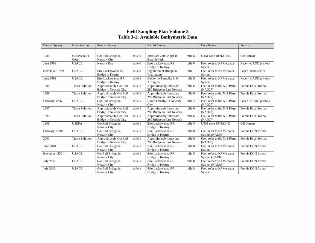
Field Sampling Plan Volume 3 Table 3-1: Available Bathymetric Data
Date of Survey Organization Start of Survey End of Survey Coordinates Source
1985 USEPA & IT Corp
ConRail Bridge in Newark City
mile 1 Interstate 280 Bridge in East Newark
mile 6 UTM zone 18 NAD 83 GIS format
June 1989 USACE Newark Bay mile 0 Erie Lackawanna RR Bridge in Kearny
mile 8 Feet; refer to NJ Mercator System
Paper - CADD printout
November 1989 USACE Erie Lackawanna RR Bridge in Kearny
mile 8 Eighth Street Bridge in Wallington
mile 15 Feet; refer to NJ Mercator System
Paper - handwritten
June 1992 USACE Erie Lackawanna RR Bridge in Kearny
mile 8 Belleville Turnpike in N. Arlington
mile 9 Feet; refer to NJ Mercator System
Paper - CADD printout
1995 Tierra Solution Approximately ConRail Bridge in Newark City
mile 1 Approximately Interstate 280 Bridge in East Newark
mile 6 Feet; refer to the NJS Plane (NAD27)
Premis Excel format
1996 Tierra Solution Approximately ConRail Bridge in Newark City
mile 1 Approximately Interstate 280 Bridge in East Newark
mile 6 Feet; refer to the NJS Plane (NAD27)
Premis Excel format
February 1996 USACE ConRail Bridge in Newark City
mile 1 Route 1 Bridge in Newark City
mile 2 Feet; refer to the NJS Plane (NAD27)
Paper - CADD printout
1997 Tierra Solution Approximately ConRail Bridge in Newark City
mile 1 Approximately Interstate 280 Bridge in East Newark
mile 6 Feet; refer to the NJS Plane (NAD27)
Premis Excel format
1999 Tierra Solution Approximately ConRail Bridge in Newark City
mile 1 Approximately Interstate 280 Bridge in East Newark
mile 6 Feet; refer to the NJS Plane (NAD27)
Premis Excel format
1999 USEPA ConRail Bridge in Newark City
mile 1 Erie Lackawanna RR Bridge in Kearny
mile 8 UTM zone 18 NAD 83 GIS format
February 2000 USACE ConRail Bridge in Newark City
mile 1 Erie Lackawanna RR Bridge in Kearny
mile 8 Feet; refer to NJ Mercator System (NAD83)
Premis DGN format
2001 Tierra Solution Approximately ConRail Bridge in Newark City
mile 1 Approximately Interstate 280 Bridge in East Newark
mile 6 Feet; refer to the NJS Plane (NAD27)
Premis Excel format
June 2001 USACE ConRail Bridge in Newark City
mile 1 Erie Lackawanna RR Bridge in Kearny
mile 8 Feet; refer to NJ Mercator System
Premis DGN format
November 2001 USACE ConRail Bridge in Newark City
mile 1 Erie Lackawanna RR Bridge in Kearny
mile 8 Feet; refer to NJ Mercator System (NAD83)
Premis DGN format
July 2002 USACE ConRail Bridge in Newark City
mile 1 Erie Lackawanna RR Bridge in Kearny
mile 8 Feet; refer to NJ Mercator System (NAD83)
Premis DGN format
July 2003 USACE ConRail Bridge in Newark City
mile 1 Erie Lackawanna RR Bridge in Kearny
mile 8 Feet; refer to NJ Mercator System
Premis DGN format

Field Sampling Plan Volume 3 Table 4-1: Summary of Field Tasks
Task
Objectives Sampling Locations and Frequency Data Generated
Bathymetry Surveys • Determine bathymetry of 17-mile stretch of Passaic River from Newark Bay to Dundee Dam
• Support hydraulic analyses and environmental modeling analyses with detailed, current data
• Identify scour/depositional areas • Support dredging and restoration design
• Bathymetry at transects • Spot elevations at each transect on each
bank
• Bathymetric data for Lower Passaic River, Hackensack River, and Newark Bay
• Spot elevation data for each river bank at each transect
• Digital map deliverables (Intergraph and ArcGIS) • Digital terrain model
Aerial Surveys • Obtain aerial photography of Lower Passaic River and candidate restoration sites
• Prepare shoreline map and mudflat delineation • Support restoration design
• Aerial survey of Lower Passaic River Study Area
• 1 inch = 100 feet (1 foot contours) and 1 inch = 30 feet (0.5 foot contours) survey plots of Passaic River shoreline integrated with bathymetric data
• Digital map deliverables (Intergraph and ArcGIS) • Digital terrain model
Supplemental Land Survey • Determine elevation, topography, and other physical features of candidate restoration sites to support restoration design
• Determine grades of side slopes of Passaic River to support design of bank stabilization/re-grading measures that may be necessary during dredging and restoration
• Determine site access and location of utilities
• Topographic survey or ground truthing of each candidate site (including shoreline to a water depth of 3 feet)
• Monument installation
• 1 inch = 40 feet (0.5 foot contours) topographic and planimetric feature maps of candidate sites
• Digital map deliverables (AutoCAD and ArcGIS) • Digital elevation model
Geophysical Surveys • Determine texture of surficial sediment to characterize Passaic River bottom
• Determine amount/extent of debris/other targets for dredging FS
• Identify significant geological layers in the sediment
• Geophysical prove-out (side scan and subbottom) at limited number of locations to evaluate survey technique usability
• Side scan sonar survey of 17-mile study area at 40 meter line spacing
• Subbottom survey (acoustic and GPR methods) of 17-mile study area at 40 meter line spacing (subject to prove-out results)
• "Ground truth" sediment grab sampling at a rate of 16 samples per river mile (approximately 275 samples)
• Subbottom program sediment cores
• Prove-out Findings and Recommendations Report • Side scan sonar sediment texture maps, contact
lists, and interpretation • Subbottom profile sediment stratigraphy maps and
interpretation (subject to prove-out results) • Descriptions of stratigraphy from subbottom
program sediment cores
Soil/Sediment Investigations
• Characterize environmental (HTRW) quality of soils/sediments at candidate sites
• Evaluate soil geotechnical properties to support restoration design, slope stability issues, and bank stabilization measure design
• Environmental sampling of hollow stem auger and/or DPT borings (approx. 2 to 8 borings per acre) at each candidate site
• Geotechnical soil sampling of soil borings at shoreline softening, wetland restoration, and/or bank stabilization sites at a rate of one boring per 50-250 feet of shoreline
• Wetland soil/sediment sampling via hand coring device and/or DPT boring at a frequency to be determined
• Field measurements (e.g., USCS classification, pocket penetrometer tests, SPT)
• Soil sample or wetland soil/sediment sample chemical data (.e.g., TCL/TAL, PCBs, PCDD/Fs)
• Soil sample geotechnical data (e.g., grain size, Atterberg limits, moisture content)

Task
Objectives Sampling Locations and Frequency Data Generated
Water Quality Investigations
• Characterize groundwater/surface water quality at candidate sites
• Potentially provide input data for Passaic River model
• One round of groundwater sampling per candidate site, generally from a minimum of 3 monitoring wells
• One round of surface water sampling (where applicable) per candidate site
• Multiple rounds (seasonal) of water level measurements
• Staff gauges
• Field parameter measurements (e.g., pH, DO, turbidity)
• Groundwater and surface water sample chemical data (e.g., TCL/TAL, PCBs, PCDD/Fs)
• Surface water sample chemical data
Hydrologic Investigations • Support feasibility analysis for restoration sites • Determine groundwater and surface water elevations, fluctuations and flow regimes via monitoring wells, piezometers, and staff gauges
• Determine channel layout and other design parameters
• Provide the basis for the horticultural design and planting of the wetland
• Study the flooding potential in offsite areas adjacent to the candidate restoration area
• Groundwater and surface water elevation data • Geomorphic and hydrologic features maps • Hydrologic-hydraulic analyses and models (e.g.,
studies of flooding potential in off-site areas adjacent to the candidate restoration site.
Socioeconomic Investigation
• Support feasibility analysis for restoration sites • Review of habitat units for each restoration alternative, reports of channel conditions, dredging sounding maps, historic dredging costs, property values adjacent to candidate sites, demographic data, restoration project cost estimates, schedules, financing plans, and statement of financial capability
• Economic analyses of restoration alternatives using Cost Efficiency and Incremental Cost Analysis via Institute of Water Resources PLAN Decision Support software.
• Documentation of social, economic, and demographic characteristics of the study area population.
• Institutional analysis of constraints/opportunities for remediation and restoration efforts
• Prioritization of restoration alternatives according to socioeconomic effectiveness
• Evaluation of effects of restoration alternatives on environmental justice
• Assessment of institutional and financial implementability of restoration alternatives
• Documentation of modeling tools used to assess
Real Estate Investigation • Support feasibility analysis for restoration sites • Review of costs for lands, easements, rights-of-way, relocations, and disposal areas in USACE baseline cost estimate
• Preparation of Physical Takings Analysis in regard to potential induced flooding
• Evaluation of relocation assistance benefits, mineral rights, feasibility of obtaining lands, easements and rights-of-way (LER) for the project
• Real Estate Plan (REP) including structure inventory, land use study, Physical Taking analysis (if required), rights-of-entry for environmental investigations, a detailed schedule of land acquisition milestones, a discussion of the impacts of contamination on the real estate acquisition process, an assessment of local landowner support/opposition, and descriptions of other relevant real estate issues.

Field Sampling Plan Volume 3 Table 4-2: Guidance for Land Surveying
Feature Format
Type GIS (ArcView) Attributes CADD
Layers Index grids depicting extents of map and orthophoto tiles Polygon Grid ID Map Tile
Ortho Tile Waterbodies Polygon Waterbody Wetlands Polygon Wetlands Treeline/Foliage outlines Polygon Vegetation Shoreline Polygon Islands Polygon
Hydrologic features: stream, shoreline Line
Fields: 1. Continuous Flow 2. Intermittent Flow
Hydrology (Use dashed lines for Intermittent Flow)
Fences Line Fences Roads (curbline) Line Roads Dirt Roads/Trails Line Unpaved Unpaved- dashed line Edge of Pavement Line Paved Paved- full line Railroad centerlines Line Railroads
Buildings/Structures Polygon Structure Type
Separate Layer per Type: 1. Building 2. Shed 3. Foundation 4. Tank/Silo 5. etc…
Topography(1)(2) (contours)
Fields: 1. Elevation
(Numeric, 2 decimal)
1. Index (Boolean):every 5th contour
Annotation (CADD & GIS) 3. Obscured (Boolean)
1. Intermediate 2. Index (every 5th contour) (Used dashed line style where ground is obscured. Elevation of the contour must equal ground elevation.)
Utility Structures: (hydrants, manholes, catch basin, etc.) Structure Type
(One GIS theme) Utility Structure Symbolize (hydrant, manhole MH, catch basin CB, etc.) (One CADD Layer)
Dams/Locks Polygon Separate Layer per Type Utility Poles Point Separate Layer Control Points Point (x-y-z used for survey control)
Gridlines (Gradicules) Line
The grid will be shown on the topographic mapping at no less than 200' intervals; coordinates for both easting and northing will be shown on the topographic mapping at no less than 1000' intervals with easily recognizable tics and will be based on NAD83 (NJ requirements). Vertical elevation will be the NGVD 1929.
Breaklines(3) Line Hard or Soft (1) Includes detailed survey of shoreline slope and shallow water to a water depth of 3 feet. (2) A contour will be defined as an imaginary line of constant elevation on the ground surface. All contours derived from photogrammetric methods will be recorded in this data set. A contour which intersects a manmade feature such as a house will be recorded as a straight line from the point at which it enters the structure to the point at which it exits the structure. These contours will be coded as hidden contours. Contours will not be 'stacked' at vertical objects but will terminate at the beginning of such objects and continue from the end. Contours that may be obscured by vegetation are to be coded as approximate. Contour lines should be smooth and not appear broken. Contour accuracy will be checked by conventional field observation methods.
(3) Breaklines are linear features used to define and control surface smoothness and continuity in relation to the digital orthophotography and the contour data set. Breaklines contain x, y, and z values. The z value along a breakline can be constant, or can vary throughout its length. The data set will contain both soft breaklines and hard breaklines.

Field Sampling Plan Volume 3 Table 4-3: Measurement Quality Objective
Parameter Acceptable Criteria Unit of
Measure Validation Frequency Corrective Action
Source level +/- 2.5% decibel Beginning and end of each
survey line Re-survey if out of
compliance Amplifier Gain +/- 1.0% decibel Same as above Same as above Receiver Gain +/- 2.5% decibel Same as above Same as above
Receiver Signal/Noise Greater than 5 ratio Continuous Re-survey if not immediately corrected
Navigation (Horizontal)
+/- 1 meter Continuous Re-survey if not immediately corrected
Navigation (Vertical)
+/- 0.1 meter Continuous Re-survey if not immediately corrected

APPENDIX A HTRW DRILLING LOG FORM

�������� �
������� ���� �����
��
� �������� �� ��� �� ���������� ������� ��������� �����������
�� ������� � ������� ��� �������� �� ������ ��������
�� �������� ������� �� ������� ��������� �� ��� �� ��������� �����
�� �������������� ����������� �� ����� �� ���� �� ����������� �����������
�� �� � ��� ���� �� �!������� "� ���� ��� ������� #� ���� ��� ���������
"� ���� �� ������� $� ����� ��� �� ���� ��%��
#� ���&���� �� ���������� '� ����������� �� ���
$� ���� ������� ���� ���& ��� ���� �� ���������
'� ����� ���� �� ��� �� ��������� �� ���������
����( ���� ������ ) ������ ���� �����
����� *����+ �������������� �� �������� ���� �,� ����� ������ �����&�
*����+ ������
�
�
���� ����������
�
�
"

��������
������� ���� �����
� ��
� �������� ��� ���� �� ���������
�� ������� �� ��������� �� ���������
����( ���� ������ ) ������ ���� �����
����� *����+ �������������� �� �������� ���� �,� ����� ������ �����&�
*����+ ������
"
'
�
���� ����������
#
$
�
�
�

APPENDIX B SOIL SUMMARY SHEET

�������������������� ������ ��
������������ �������
������������ �� ������������� ���
������������������
��������� �� ��������������� ����
����� ����������� ����������� �� �������������
������� ��� �������������� ��������������������
��� ����� ���������� �� ��������������� ����
���������� ��� �� �������������
�� �������� �������� ������ �� �� ��������
�� !���� ���������"�������� ������������ ���� ���
�������� �� �������������
������������������ ���
����� ��� ������� ��������� �� ����������������
������ �������� ��� �������������� ��������������� �������������
�� ������� �� �����������������
������� ��� ��������������� �������������
�� �#�� ����� ���������� ������ ������ �� �� ������
�����$� ���������� ��� ���������"�������� ������ ���� ���
�������� !���� �������� �� ����������
������������ ���
������������ �������������
� ��������%���������� ����
�������������������������
�� ��� ������ ���� ��� �
���� �� ��&�������� ���������������������� �
������� ��� ��� ������ � ���������� ��� ����������
��� ���� ������������������� �
���������������
���������� ������������
��������������� ��� �
����� ��� ������������ ����������
������ �� ������ ����������������
�� ������� �� ��&�������� ����� �����
������� ��� ��� ���� ��� ������ �� ����������������������
�� �#�� ���� ��� ��� ����� �����
�����$� � ����������������������� �
�������� ��� �������������
������������������ � ��� ����������������
�� ������������������ ��
�'()�*+,-�)*�(./�'*/0�1��23024(1/�-�.0/.)23/�4)(**2524(12�3* .(4/���6��1��6#���5�1�1()�*(,7)/
���������������))�*28/�5.(412�3*�(./�/9'())+�./7./*/31/0 �,/���6#��1��:����5�1�1()�*(,7)/
�����������������3/�*28/�5.(412�3�2*�0�,23(31 �.(;/))+��*(30+��*2)1+��4)(+/+���:��
��� ������6<6=�23 ����1�������5�1�1()�*(,7)/
������6<6=�23 �1��6<#�23
��������6<#�23 �1��6#�23 �.(;/)
�� ������./(1/.�1>(3�6#�23 4�?�:<!@���:@
���%� ���,())�/..(124�0/7�*21 5�?�:<!@���:<6=@ � �1(30(.0
�������/3124')(.�0/7�*21 (30 2/;/�28/
��������)1/.3(123A�*/(,*��.�)(+/.*��5�*(30��*2)1��.�4)(+ 4�?�:<6=@����<=!@ !���6�
�������������3/��.�)/**�7/.�5��1��5�1>24B3/** ,�?��<=!@���6<=!@ 6����!�
���&��� �����./�1>(3��3/�7/.�5��1��5�1>24B3/** 5�?�6<=!@���� ��#C@ !����#��
�)(*12421+ ,/(.� /*1 >./(0�28/
����37)(*124���4.',-)/*�D21>�)2A>1�523A/.�7./**'./ A.211+��.�.�'A> 4.(4B*
����D�7)(*12421+���4.',-)/*�D21>�*�,/�523A/.�7./**'./ .�'A>�1��*,��1> 6<!���6<E@
���/02',�7)(*2421+���-./(B*�231��72/4/*��.�4.',-)/*�D21>�4�3*20/.(-)/�523A/.�7./**'./ *,��1>�F�0')) 6<6=@
���2A>��)(*12421+���4(3G1�-/�-.�B/3�D21>�523A/.�7./**'./��D2))�-./(B�231��72/4/*�-/1D//3 *>23+ 6<:#@
����1>',-�(30�(�>(.0�*'.5(4/
��/.+�7)(*124���4(3G1�-/�-.�B/3�-/1D//3�1>',-�(30�(�>(.0�*'.5(4/ ;/.+�*>23+�F�D(H+ 6<=!@

APPENDIX C HTRW WELL INSTALLATION DIAGRAM
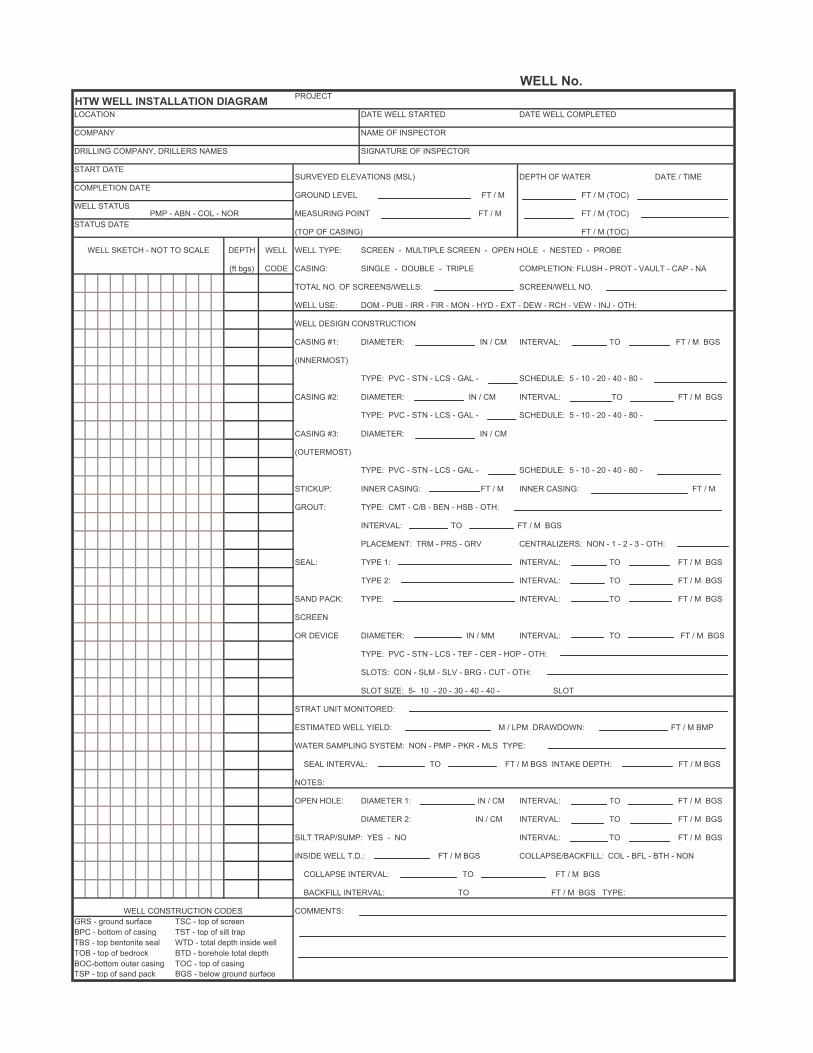
�������������
�������������� ���������������
������ ��� ���� ������ ��� ���� ���������
������ ��� �� ��������
������ ������� ������� ���� ������� �� ��������
���� ����������� �������� ����� ����� �� ���� ��� � ���
��������� ��������� ����� �� � � �� � � �����
���� �������� � �� � ��� � ��� ������� ���� �� � � �� � � �����
����� ������� �� ����� �� � � �����
���� ������ � ��� �� ���� ����� ���� ���� ����� ������ � ������� ������ � ���� ���� � ������ � �����
�� !"#� ���� ����� ����� � ������ � ����� ���������� ����� � ���� � ���� � �� � �
���� ��$ �� �������������� ����������� ��$
���� ���� ��� � ��� � �� � �� � ��� � ��� � �%� � ��� � ��� � ��� � �� � ����
���� ����� �����������
���� &'� ������� � � �� ������� �� �� � � ���
����������
����� ��� � ��� � ��� � �� � ��������� ( � ') � *) � +) � ,) �
���� &*� ������� � � �� ������� �� �� � � ���
����� ��� � ��� � ��� � �� � ��������� ( � ') � *) � +) � ,) �
���� &-� ������� � � ��
�����������
����� ��� � ��� � ��� � �� � ��������� ( � ') � *) � +) � ,) �
������� ���� ����� �� � � ���� ����� �� � �
������ ����� ��� � ��� � ��� � ��� � ����
������� �� �� � � ���
��������� ��� � ��� � ��� ������.���� ��� � ' � * � - � ����
���� ���� '� ������� �� �� � � ���
���� *� ������� �� �� � � ���
��� ���� ����� ������� �� �� � � ���
������
�� ����� ������� � � �� ������� �� �� � � ���
����� ��� � ��� � ��� � ��� � ��� � ��� � ����
������ ��� � ��� � ��� � ��� � ��� � ����
���� �.�� (� ') � *) � -) � +) � +) � ����
���� ��� ���������
������� ���� ����� � � ��� �������� �� � � ���
���� ������ ������� ��� � ��� � ��� � ��� �����
��� ������� �� �� � � ��� ���� ������ �� � � ���
������
���� ����� ������ '� � � �� ������� �� �� � � ���
������ *� � � �� ������� �� �� � � ���
��� ��������� ��� � �� ������� �� �� � � ���
���� ���� �$�$� �� � � ��� ��������������� ��� � ��� � ��� � ���
������� ������� �� �� � � ���
������ ������� �� �� � � ��� �����
���� ����������� ����� ���������
��� � "/0123 #1/�456 ��� � 07 0� #5/662
��� � !0 08 0� 54#92" ��� � 07 0� #9: /47
��� � 07 !62 029 6 #64: ��� � 0 4: 367 ; 92#936 <6::
��� � 07 0� !63/05= ��� � !0/6;0:6 0 4: 367 ;
����!0 08 01 6/ 54#92" ��� � 07 0� 54#92"
��� � 07 0� #423 745= ��� � !6:0< "/0123 #1/�456

APPENDIX D WELL DEVELOPMENT FORM

������������� ���� ����
������������������������ ��
������������ �������������� ����� �����������������������
����������� �������������� �����
������������������� ���� ������������� �����
������������������ ����������
� !"# ��������� ������ �
"$ �%&'
�() �*" & *" � )!� �$+,%-"� �� !� �� �%&.(,("/ ���0
12"3 1)45)(+3 1�3 1)65-)3 1)'5�3 1+"%3
���������
�� ����� �����������

APPENDIX E HTRW WELL SAMPLING FORM

�������������� ���� ����
��������� ����������� ��
������������ �������������� ����� �����������������������
����������� �������������� �����
������������������� ���� ������������� �����
������������������ ���������� ��������� ��������
�!"#$ ��������� ������ �
#% �&'(!
�)*! �+#!' +#! �!*"� �%,-&.#� �� "� �� �&'/)-)#0 ���
12#3 1*45*),3 1�3 1*65.*3 1*(5�3 1,#&3
���������
�� ����� �����������