SCL Manual for MSST-S Drives - MOONS' - moving in better...
130
SCL Manual for MSST-S Drives SCL Commands for the MSST5-S and MSST10-S Step Drives SHANGHAI AMP&MOONS’AUTOMATION CO., LTD.
Transcript of SCL Manual for MSST-S Drives - MOONS' - moving in better...
SCL Manual for MSST-S DrivesSCL Commands for the MSST5-S and MSST10-S Step Drives
SHANGHAI AMP&MOONS’AUTOMATION CO., LTD.

SCL Manual for MSST-S Drive Rev.1
I
Contents
Introduction.....................................................................1What is SCL? .................................................................................1SCL Details .....................................................................................1
Getting Started ................................................................3Step 1: Install software .....................................................................3Step 2: Configure your MSST-S drive using ST Configurator ..........3Step 3: Get familiar with SCL commands ........................................4Step 4: Develop your application ......................................................5
Commands ........................................................................6Buffered Commands .......................................................................6Immediate Commands .....................................................................6
Command Summary ...............................................................................6Motion Commands ...........................................................................7Configuration Commands ...............................................................8Buffer Commands ...........................................................................9Status Commands ..........................................................................9I/O Commands .................................................................................10Register Commands .......................................................................10
Command Listing ....................................................................................11AC - Acceleration Rate ...................................................................12AD - Analog Deadband ...................................................................13AF - Analog Filter ............................................................................14AG - Analog Velocity Gain ................................................................15AI - Alarm Reset Input (EN input) ....................................................16AL - Alarm Code .............................................................................17AM - Max Acceleration .....................................................................18AO - Alarm Output ..........................................................................19AP - Analog Position Gain ..............................................................20AR - Alarm Reset (IMMEDIATE).......................................................21AT - Analog Threshold ......................................................................22AV - Analog Offset Value ..................................................................23AX - Alarm Reset (BUFFERED) ......................................................24AZ - Analog Zero ..............................................................................25BD –Brake Disengage Delay ...........................................................26BE - Brake Engage Delay ...............................................................27
SCL Manual for MSST-S Drive Rev.1
II
BO - Brake Output .......................................................................... 28BR - Baud Rate .............................................................................. 29BS - Buffer Status ........................................................................... 30CC - Change Current ...................................................................... 31CD - Idle Current Delay Time............................................................ 32CE - Communication Error................................................................ 33CF - Anti-Resonance Filter Frequency ............................................ 34CG - Anti-Resonance Filter Gain ..................................................... 35CI - Change Idle Current .................................................................. 36CJ - Commence Jogging ................................................................ 37CM - Command Mode ...................................................................... 38CS - Change Speed ......................................................................... 39CT - Continue................................................................................... 40DA - Define Address ....................................................................... 41DC - Change Distance .................................................................... 42DE - Deceleration Rate ................................................................... 43DI - Distance / Position ................................................................... 44DL - Define Limits ........................................................................... 45EG - Electronic Gearing.................................................................... 47FC - Feed to Length with Speed Change ........................................ 48FD - Feed to Double Sensor ........................................................... 49FE - Follow Encoder ....................................................................... 50FI - Filter Input .................................................................................. 51FL - Feed to Length ........................................................................ 53FM - Feed to Sensor with Mask Distance ....................................... 54FO - Feed to Length and Set Output ............................................... 55FP - Feed to Position ...................................................................... 56FS - Feed to Sensor ......................................................................... 57FY - Feed to Sensor with Safety Distance ...................................... 58HG - 4th Harmonic Filter Gain ........................................................ 59HP - 4th Harmonic Filter Phase ...................................................... 60HW - Hand Wheel ........................................................................... 61IA - Immediate Analog ..................................................................... 62IC - Immediate Current ................................................................... 63ID - Immediate Distance ................................................................. 64IF - Immediate Format .................................................................... 65IH - Immediate High Output ............................................................ 66IL - Immediate Low Output ............................................................... 67

SCL Manual for MSST-S Drive Rev.1
III
IO - Output Status .......................................................................... 68IP - Immediate Position .................................................................. 69IS - Input Status ............................................................................. 70IT - Immediate Temperature ............................................................ 71IU - Immediate Voltage .................................................................... 72IV - Immediate Velocity .................................................................. 73JA - Jog Acceleration ..................................................................... 74JC - Velocity (Oscillator) Mode Second Speed .............................. 75JD - Jog Disable .............................................................................. 76JE - Jog Enable ............................................................................... 77JL - Jog Decel ................................................................................ 78JS - Jog Speed .............................................................................. 79MD - Motor Disable ........................................................................ 80ME - Motor Enable ......................................................................... 81MN - Model Number ........................................................................ 82MO - Motion Output ....................................................................... 83PB - Power-up Baud Rate ............................................................. 84PC - Power-up Current .................................................................... 85PI - Power-up Idle Current ............................................................. 86PM - Power-up Mode ..................................................................... 87PR - Protocol ................................................................................... 88PS - Pause ...................................................................................... 92RE - Restart ................................................................................... 93RL - Register Load (IMMEDIATE).................................................... 94RS - Request Status ...................................................................... 96RU - Register Upload ...................................................................... 97RV - Revision Level ......................................................................... 98SA - Save Parameters ................................................................... 99SC - Status Code ........................................................................... 100SF - Step Filter Frequency............................................................... 101SH - Seek Home ............................................................................ 102SI - Enable Input (EN input) ........................................................... 103SJ - Stop Jogging ........................................................................... 104SK - Stop & Kill Buffer...................................................................... 105SO - Set Output ............................................................................. 106SP - Set Position ............................................................................ 107SS - Send String ............................................................................ 108ST - Stop.......................................................................................... 109
SCL Manual for MSST-S Drive Rev.1
IV
TD –Transmit Delay ........................................................................ 110VC –Change Velocity ....................................................................111VE –Velocity ..................................................................................112WI –Wait for Input ......................................................................... 113WT –Wait Time ............................................................................... 114
Data Registers .............................................................. 115Read-Only data registers ............................................................... 115Read/Write data registers ............................................................... 115
Data Register Assignments......................................................................115Read-Only data registers: a - z ...................................................... 116Read/Write data registers: A - Z ..................................................... 117
Appendix A: Host Serial Communications ............ 119
Appendix B: Alarm and Status Codes ..................... 122

SCL Manual for MSST-S Drive Rev.1
- 1 -
IntroductionThank you for purchasing an MOONS' stepper drive. We hope you will find that performance, price,
and ease of use make our products the best value for your application.
The Serial Command Language (SCL) can be used in several MOONS' drives. This manual focuseson using SCL with the MSST5-S and MSST10-S drives only.
NOTE: Using SCL with other MOONS' drives is detailed in other manuals. Please visit ourweb site www.moons.com.cn to view and download these manuals.
NOTE: This manual only covers details related to using SCL with the MSST-S drives. For allother aspects of applying your MSST-S drive, including hardware configuration, I/O, andsoftware settings, view MSST5(10)-S User Manual and the Help file contained in the STConfigurator software. The manual and software can be downloaded for free fromwww.moons.com.cn.
What is SCL?SCL was to give users a simple way to control a motor drive via a serial port. This eliminates the
need for separate motion controllers or indexers to supply Pulse & Direction signals to your stepper drive.It also provides an easy way to interface to a variety of other industrial devices like PLCs and HMIs, whichmost often have standard or optional serial ports for communicating to other devices.
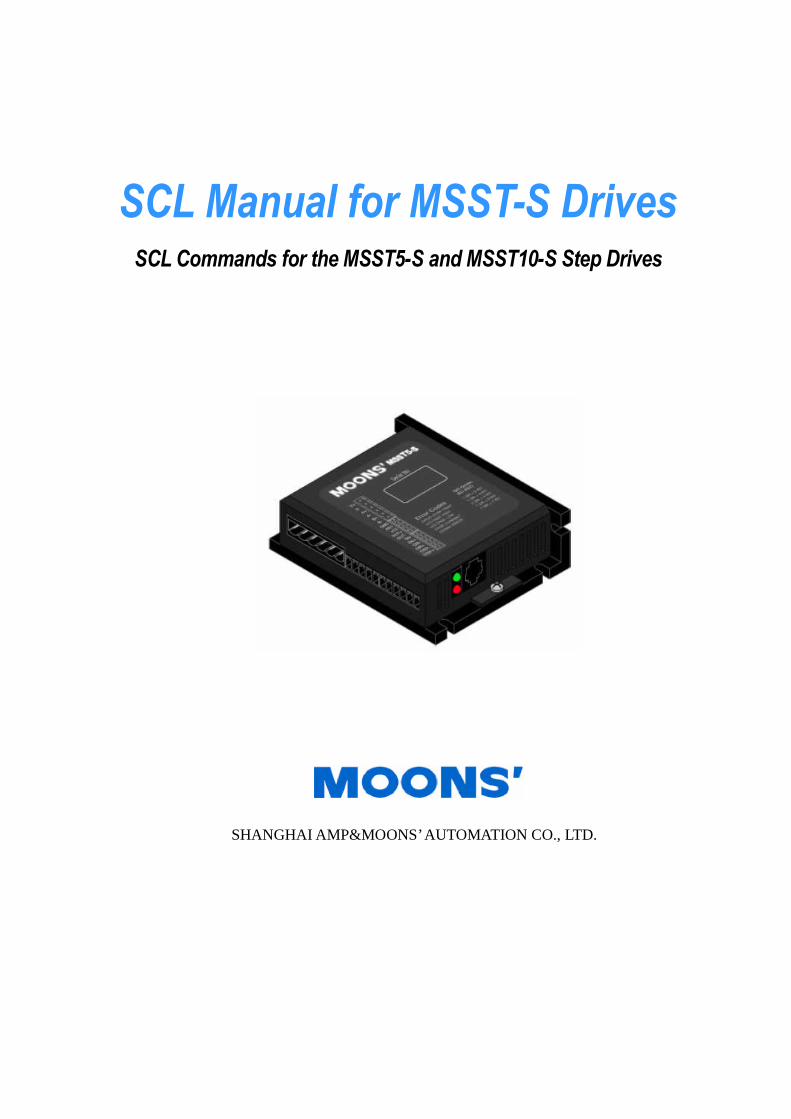
MSST-S drives come with one RS-232 serial port. This port is an RJ-11 jack (6P4C) as shown in thepicture below.
To use SCL in an application means you will have a host device, such as a PC, a PLC, or an HMI, con-nected to the drive’s serial port and using that connection to send commands to the drive. The set ofcommands defined by SCL includes commands for motion of the step motor, commands for using thethree digital inputs, one analog input, and one digital output of the drive, as well as commands forconfiguring different aspects of the drive like motor current and microstep resolution.
When in SCL mode, an MSST-S drive receives commands from the host into a command buffer, andthen executes the received commands directly out of that buffer. One thing you cannot do with anMSST-S drive is to create a stored program that the drive can run stand-alone. For that you shouldconsider the MSST-Q or MSST-Si drives, which are designed for stored program execution.
SCL DetailsThere are two basic parts to the serial communications used in SCL: the physical connection
between the drive and the host, and the communications protocol.
The physical connection between the drive and the host is based on standard RS-232 connections.With PCs this is one of the COM ports on your computer. With PLCs and HMIs look for connections labeledRS-232, PLC port, AUX port, ASCII, or something similar that would indicate a serial RS-232 connection.There are only three connections to be made between the drive and the host: transmit (Tx), receive (Rx),and signal ground (GND).
SCL Manual for MSST-S Drive Rev.1
- 2 -
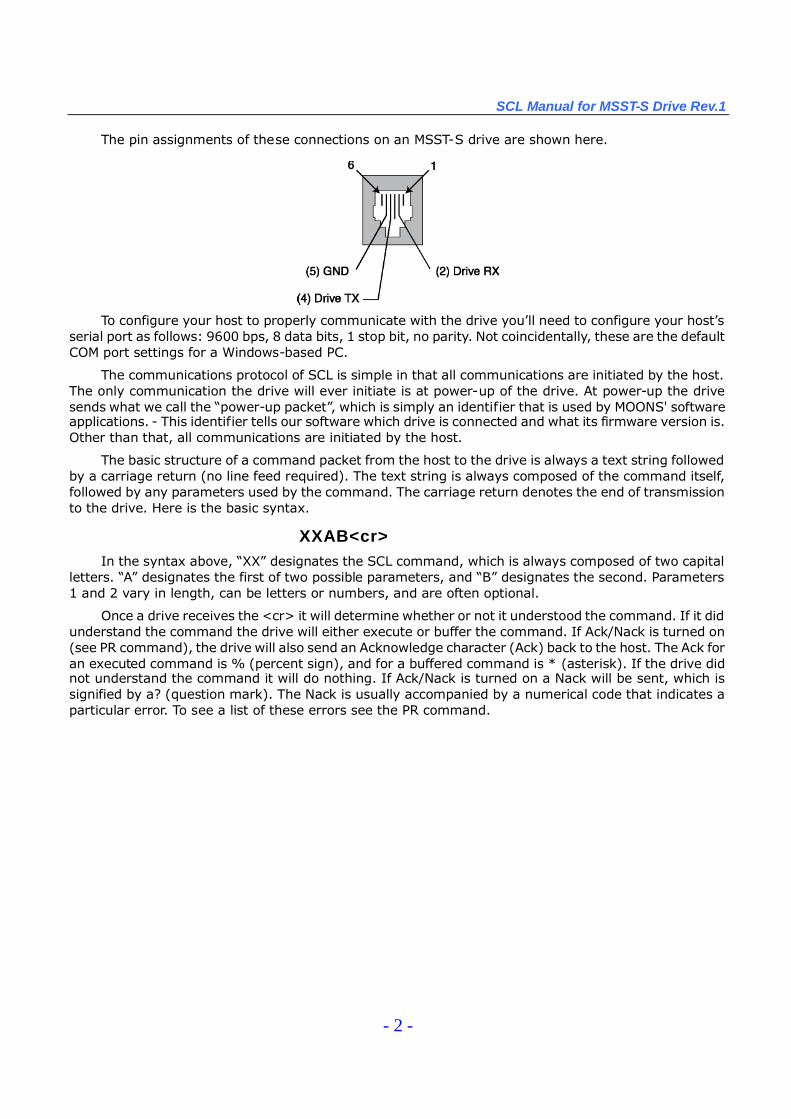
The pin assignments of these connections on an MSST-S drive are shown here.
To configure your host to properly communicate with the drive you’ll need to configure your host’sserial port as follows: 9600 bps, 8 data bits, 1 stop bit, no parity. Not coincidentally, these are the defaultCOM port settings for a Windows-based PC.
The communications protocol of SCL is simple in that all communications are initiated by the host.The only communication the drive will ever initiate is at power-up of the drive. At power-up the drivesends what we call the “power-up packet”, which is simply an identifier that is used by MOONS' softwareapplications. - This identifier tells our software which drive is connected and what its firmware version is.Other than that, all communications are initiated by the host.
The basic structure of a command packet from the host to the drive is always a text string followedby a carriage return (no line feed required). The text string is always composed of the command itself,followed by any parameters used by the command. The carriage return denotes the end of transmissionto the drive. Here is the basic syntax.
XXAB<cr>In the syntax above, “XX”designates the SCL command, which is always composed of two capital
letters. “A”designates the first of two possible parameters, and “B”designates the second. Parameters1 and 2 vary in length, can be letters or numbers, and are often optional.
Once a drive receives the <cr> it will determine whether or not it understood the command. If it didunderstand the command the drive will either execute or buffer the command. If Ack/Nack is turned on(see PR command), the drive will also send an Acknowledge character (Ack) back to the host. The Ack foran executed command is % (percent sign), and for a buffered command is * (asterisk). If the drive didnot understand the command it will do nothing. If Ack/Nack is turned on a Nack will be sent, which issignified by a? (question mark). The Nack is usually accompanied by a numerical code that indicates aparticular error. To see a list of these errors see the PR command.
SCL Manual for MSST-S Drive Rev.1
- 3 -
Getting StartedTo get up running with your MSST-S drive and SCL as quickly as possible, follow the basic steps
below.
Step 1: Install softwareYour MSST-S stepper drive was shipped with User Manual and CD-ROM containing all of the
software applications available from MOONS' drives. If you don’t have a copy of this CD-ROM, you canalso visit www.moons.com.cn to download software applications for free.
From the CD-ROM or from a download, install ST Configurator and SCL Setup Utility on yourWindows-based PC. ST Configurator will be used to configure your drive and put it into SCL mode. SCLSetup Utility will be used to practice with SCL commands.
NOTE: For laptop computers without a serial port you will have to use a USB-Serial adapter or a PCMCIA-Serial adapter.
Step 2: Configure your MSST-S drive using ST ConfiguratorIf you haven’t already done so, unpack your MSST-S drive and step motor and collect them
together near your PC. You’re going to need the following items to begin developing your application.
An MSST5-S or MSST10-S stepper drive
A 2-phase step motor. MOONS' offers a number of step motors for use with the MSST seriesdrives. Of course you can use your own step motors.
The programming cable supplied with your MSST-S drive (9-pin D-sub at one end, RJ-11 modular connector at the other).
A small, flat-blade screwdriver (supplied with your MSST-S drive).
A 24 or 48 VDC power supply.
IMPORTANT: Never connect a step motor to your MSST-S drive with power applied to the drive.Always make sure your DC power supply is either of f o r disconnected from the MSST-S drive whenconnecting or disconnecting your step motor.
Connect the 2-phase step motor to your MSST-S drive. Then connect your MSST-S drive toyour PC using the programming cable. Launch ST Configurator. Power your drive ON. If powerwas ON to the drive when you launched ST Configurator, power the drive OFF, then back ON.
Configure your motor by clicking the “Motor”button on the main screen of ST Configurator. Usethe Help file contained in ST Configurator for details on configuring your drive for the particular stepmotor you have.
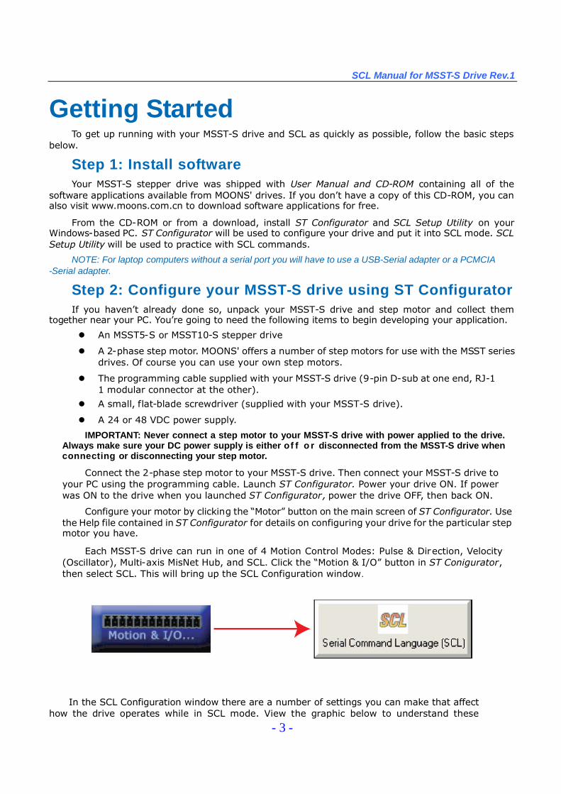
Each MSST-S drive can run in one of 4 Motion Control Modes: Pulse & Direction, Velocity(Oscillator), Multi-axis MisNet Hub, and SCL. Click the “Motion & I/O”button in ST Conigurator,then select SCL. This will bring up the SCL Configuration window.
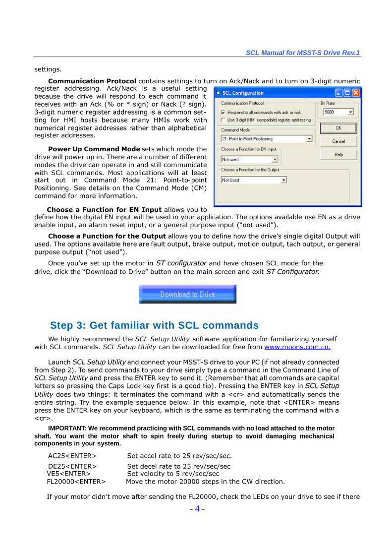
In the SCL Configuration window there are a number of settings you can make that affecthow the drive operates while in SCL mode. View the graphic below to understand these
SCL Manual for MSST-S Drive Rev.1
- 4 -
settings.
Communication Protocol contains settings to turn on Ack/Nack and to turn on 3-digit numericregister addressing. Ack/Nack is a useful settingbecause the drive will respond to each command itreceives with an Ack (% or * sign) or Nack (? sign).3-digit numeric register addressing is a common set-ting for HMI hosts because many HMIs work withnumerical register addresses rather than alphabeticalregister addresses.
Power Up Command Mode sets which mode thedrive will power up in. There are a number of differentmodes the drive can operate in and still communicatewith SCL commands. Most applications will at leaststart out in Command Mode 21: Point-to-pointPositioning. See details on the Command Mode (CM)command for more information.
Choose a Function for EN Input allows you todefine how the digital EN input will be used in your application. The options available use EN as a driveenable input, an alarm reset input, or a general purpose input (“not used”).
Choose a Function for the Output allows you to define how the drive’s single digital Output willused. The options available here are fault output, brake output, motion output, tach output, or generalpurpose output (“not used”).
Once you’ve set up the motor in ST configurator and have chosen SCL mode for thedrive, click the “Download to Drive”button on the main screen and exit ST Configurator.
Step 3: Get familiar with SCL commandsWe highly recommend the SCL Setup Utility software application for familiarizing yourself
with SCL commands. SCL Setup Utility can be downloaded for free from www.moons.com.cn.
Launch SCL Setup Utilityand connect your MSST-S drive to your PC (if not already connectedfrom Step 2). To send commands to your drive simply type a command in the Command Line ofSCL Setup Utility and press the ENTER key to send it. (Remember that all commands are capitalletters so pressing the Caps Lock key first is a good tip). Pressing the ENTER key in SCL SetupUtility does two things: it terminates the command with a <cr> and automatically sends theentire string. Try the example sequence below. In this example, note that <ENTER> meanspress the ENTER key on your keyboard, which is the same as terminating the command with a<cr>.
IMPORTANT: We recommend practicing with SCL commands with no load attached to the motorshaft. You want the motor shaft to spin freely during startup to avoid damaging mechanicalcomponents in your system.
AC25<ENTER> Set accel rate to 25 rev/sec/sec.
DE25<ENTER> Set decel rate to 25 rev/sec/secVE5<ENTER> Set velocity to 5 rev/sec/secFL20000<ENTER> Move the motor 20000 steps in the CW direction.
If your motor didn’t move after sending the FL20000, check the LEDs on your drive to see if there
SCL Manual for MSST-S Drive Rev.1
- 5 -
is an error present. If so send the AR command (AR<ENTER>) to clear the alarm. If after clearing thealarm you see a solid green LED it means the drive is disabled. Enable the drive by sending the MEcommand (ME<ENTER>) and verify that you see a steady, flashing green LED. You might also want toreview your settings in ST Configurator to make sure the motor current is set properly. Then try theabove sequence again.
Here is another sample sequence you can try.
JA10<ENTER> Set jog accel rate to 10 rev/sec/secJL10<ENTER> Set jog decel rate to 10 rev/sec/secJS1<ENTER> Set jog speed to 1 rev/secCJ<ENTER> Commence joggingCS-1<ENTER> Change jog speed to 1 rev/sec in CCW directionSJ<ENTER> Stop jogging
In the above sequence notice that the motor ramps to the new speed set by CS. This ramp isaffected by the JA and JL commands. Try the same sequence above with different JA, JL, JS, and CSvalues to see how the motion of the motor shaft is affected.
Step 4: Develop your application
This step will involve different things for different users. You’ll probably want to spend sufficienttime getting familiar with SCL commands using SCL Setup Utility before getting to this step, but onceyou have consider the following.
If your host is a PC you’ve already done a lot of the hardware configuration necessary for yourapplication. The rest of your application will involve developing your PC applications to properly sendSCL commands to your drive. Which application or language you use, whether it be VisualBasic, C++,LabView, a proprietary vision system application, or something else, is up to you. MOONS' offers somesample VisualBasic code on its web site to show how SCL commands can be sent from awindows-based PC application. You can visit www.moons.com.cn to download it.
If your host is a PLC you’ll have to connect and configure the ASCII module, RS-232 port or Auxserial port on your PLC according to the pin assignments and COM port settings listed in theIntroduction section. From there you’ll have to be able to send text strings followed by carriage returnsfrom the PLC.
If your host is an HMI you’ll have to connect and configure the serial port of the HMI in the sameway as with a PLC, as well as be able to send commands in the proper syntax to the drive.

SCL Manual for MSST-S Drive Rev.1
- 6 -
CommandsThere are two basic types of SCL commands: buffered and immediate. Buffered commands are
loaded into and executed out of your drive’s command buffer. Immediate commands are not buffered:when received by the drive they are executed immediately.
Buffered CommandsAfter being loaded into the command buffer, buffered commands are executed one at a time. If you
send two buffered commands to the drive in succession, like a Feed to Length (FL) command followedby a Send String (SS) command, the SS command sits in the command buffer and waits to executeuntil the FL command is completed. The command buffer can be filled up with commands for sequentialexecution without the host controller needing to wait for a specific command to execute before sendingthe next command. Special buffer commands, like Pause (PS) and Continue (CT), enable the buffer tobe loaded and to pause execution until the desired time.
Immediate CommandsImmediate commands are executed right away, running in parallel with a buffered command if
necessary. For example, this allows you to check the remaining space in the buffer using the BufferStatus (BS) command, or the immediate status of digital inputs using the Input Status (IS) command,while the drive is processing other commands. Immediate commands are designed to access the driveat any time and can be sent as often as needed. This allows a host controller to get information fromthe drive at a high rate, most often for checking drive status or motor position.
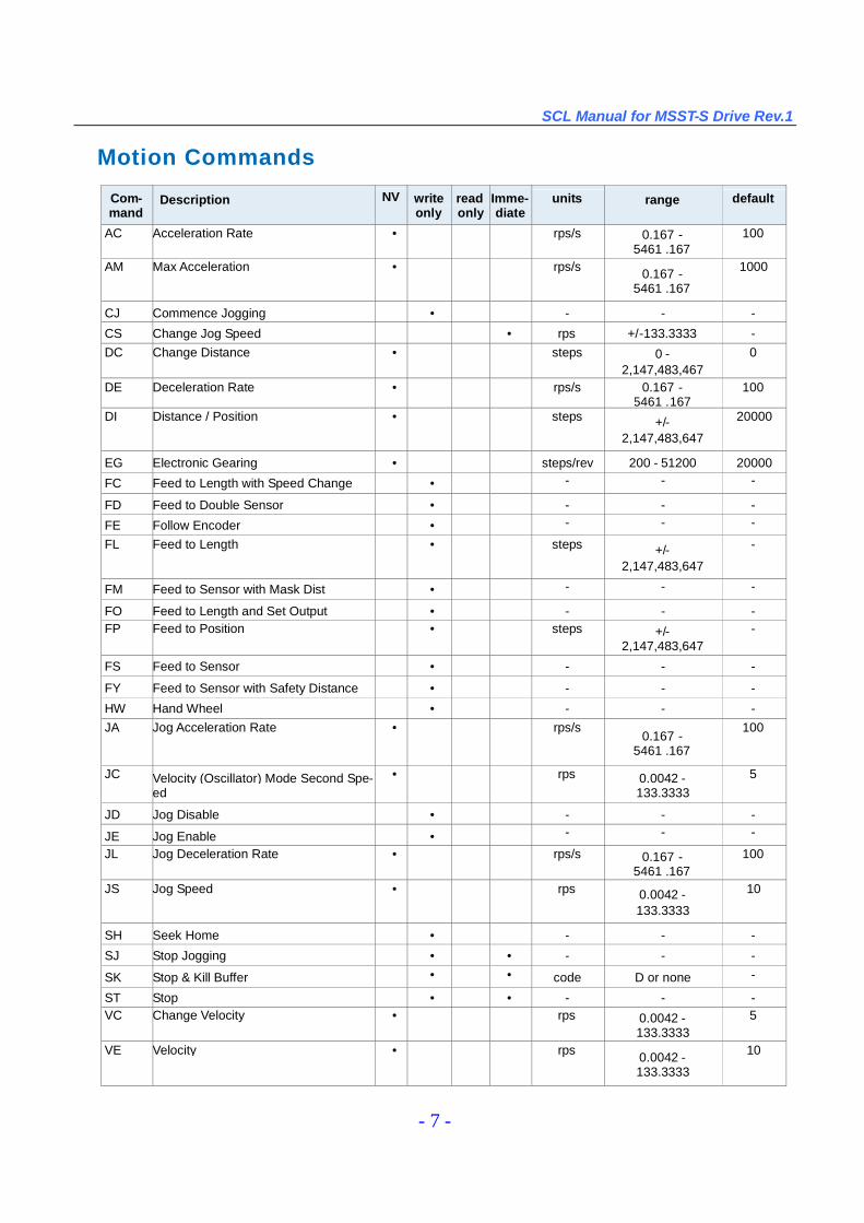
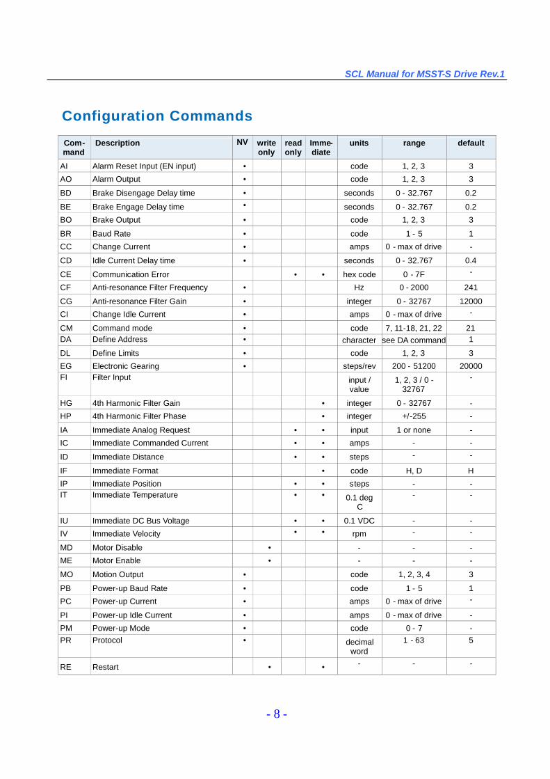
Command SummaryThe set of tables that follows lists all of the SCL commands available with your drive. In each table
there are a number of columns that give information about each command.
“Command”shows the command’s two-letter Command Code.
“Description”shows the name of each command.
“NV”designates which commands are Non-volatile: that is, which commands are saved innon-volatile memory when the SA (Save) command is sent to the drive.
“Write only”or “Read only”is checked when a command is not both Read/Write compatible.
“Immediate”designates an immediate command (all other commands are buffered).
“Units”shows a couple of different things. If a command has a parameter option it shows theunits of that parameter. If the command requests information from the drive (status command)it shows the units of the response.
“Range”shows the range of values the command can use in its parameter.
“Default”shows the default parameter value stored in the drive.
SCL Manual for MSST-S Drive Rev.1
- 7 -
Motion Commands
Com-mand
Description NV writeonly
readonly
Imme-diate
units range default
AC Acceleration Rate • rps/s 0.167 -5461 .167
100
AM Max Acceleration • rps/s 0.167 -5461 .167
1000
CJ Commence Jogging • - - -
CS Change Jog Speed • rps +/-133.3333 -DC Change Distance • steps 0 -
2,147,483,4670
DE Deceleration Rate • rps/s 0.167 -5461 .167
100
DI Distance / Position • steps +/-2,147,483,647
20000
EG Electronic Gearing • steps/rev 200 - 51200 20000
FC Feed to Length with Speed Change • - - -
FD Feed to Double Sensor • - - -
FE Follow Encoder • - - -
FL Feed to Length • steps +/-2,147,483,647
-
FM Feed to Sensor with Mask Dist • - - -
FO Feed to Length and Set Output • - - -FP Feed to Position • steps +/-
2,147,483,647-
FS Feed to Sensor • - - -
FY Feed to Sensor with Safety Distance • - - -
HW Hand Wheel • - - -JA Jog Acceleration Rate • rps/s
0.167 -5461 .167
100
JC Velocity (Oscillator) Mode Second Spe-ed
• rps 0.0042 -133.3333
5
JD Jog Disable • - - -
JE Jog Enable • - - -
JL Jog Deceleration Rate • rps/s 0.167 -5461 .167
100
JS Jog Speed • rps 0.0042 -133.3333
10
SH Seek Home • - - -
SJ Stop Jogging • • - - -
SK Stop & Kill Buffer • • code D or none -
ST Stop • • - - -VC Change Velocity • rps 0.0042 -
133.33335
VE Velocity • rps 0.0042 -133.3333
10
SCL Manual for MSST-S Drive Rev.1
- 8 -
Configuration Commands
Com-mand
Description NV writeonly
readonly
Imme-diate
units range default
AI Alarm Reset Input (EN input) • code 1, 2, 3 3
AO Alarm Output • code 1, 2, 3 3
BD Brake Disengage Delay time • seconds 0 - 32.767 0.2
BE Brake Engage Delay time • seconds 0 - 32.767 0.2
BO Brake Output • code 1, 2, 3 3
BR Baud Rate • code 1 - 5 1
CC Change Current • amps 0 - max of drive -
CD Idle Current Delay time • seconds 0 - 32.767 0.4
CE Communication Error • • hex code 0 - 7F -
CF Anti-resonance Filter Frequency • Hz 0 - 2000 241
CG Anti-resonance Filter Gain • integer 0 - 32767 12000
CI Change Idle Current • amps 0 - max of drive -
CM Command mode • code 7, 11-18, 21, 22 21DA Define Address • character see DA command 1
DL Define Limits • code 1, 2, 3 3
EG Electronic Gearing • steps/rev 200 - 51200 20000FI Filter Input input /
value1, 2, 3 / 0 -
32767-
HG 4th Harmonic Filter Gain • integer 0 - 32767 -
HP 4th Harmonic Filter Phase • integer +/-255 -
IA Immediate Analog Request • • input 1 or none -
IC Immediate Commanded Current • • amps - -
ID Immediate Distance • • steps - -
IF Immediate Format • code H, D H
IP Immediate Position • • steps - -IT Immediate Temperature • • 0.1 deg
C- -
IU Immediate DC Bus Voltage • • 0.1 VDC - -
IV Immediate Velocity • • rpm - -
MD Motor Disable • - - -
ME Motor Enable • - - -
MO Motion Output • code 1, 2, 3, 4 3
PB Power-up Baud Rate • code 1 - 5 1
PC Power-up Current • amps 0 - max of drive -
PI Power-up Idle Current • amps 0 - max of drive -
PM Power-up Mode • code 0 - 7 -PR Protocol • decimal
word1 - 63 5
RE Restart • • - - -
SCL Manual for MSST-S Drive Rev.1
- 9 -
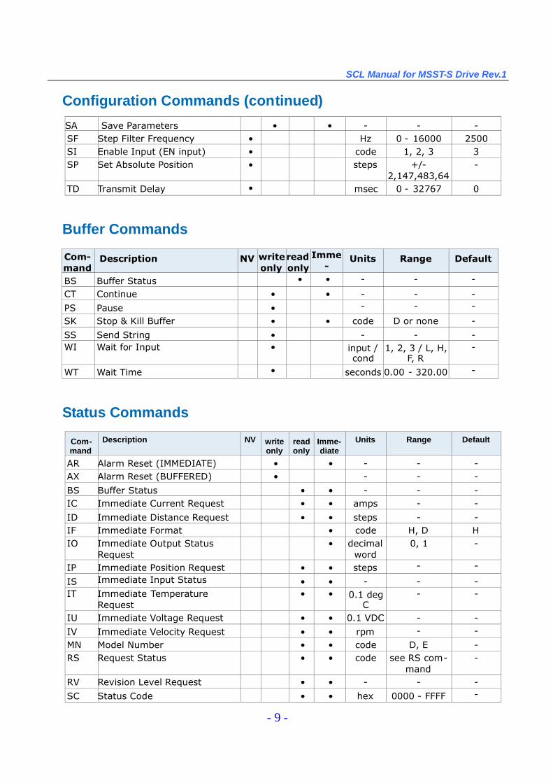
Configuration Commands (continued)
SA Save Parameters • • - - -SF Step Filter Frequency • Hz 0 - 16000 2500SI Enable Input (EN input) • code 1, 2, 3 3SP Set Absolute Position • steps +/-
2,147,483,647
-
TD Transmit Delay • msec 0 - 32767 0
Buffer Commands
Com-mand
Description NV writeonly
readonly
Imme-
diate
Units Range Default
BS Buffer Status • • - - -
CT Continue • • - - -
PS Pause • - - -
SK Stop & Kill Buffer • • code D or none -
SS Send String • - - -WI Wait for Input • input /
cond1, 2, 3 / L, H,
F, R-
WT Wait Time • seconds 0.00 - 320.00 -
Status Commands
Com-mand
Description NV writeonly
readonly
Imme-diate
Units Range Default
AR Alarm Reset (IMMEDIATE) • • - - -AX Alarm Reset (BUFFERED) • - - -
BS Buffer Status • • - - -IC Immediate Current Request • • amps - -
ID Immediate Distance Request • • steps - -IF Immediate Format • code H, D HIO Immediate Output Status
Request• decimal
word0, 1 -
IP Immediate Position Request • • steps - -
IS Immediate Input StatusRequest
• • - - -IT Immediate Temperature
Request• • 0.1 deg
C- -
IU Immediate Voltage Request • • 0.1 VDC - -
IV Immediate Velocity Request • • rpm - -
MN Model Number • • code D, E -RS Request Status • • code see RS com-
mand-
RV Revision Level Request • • - - -
SC Status Code • • hexword
0000 - FFFF -
SCL Manual for MSST-S Drive Rev.1
- 10 -
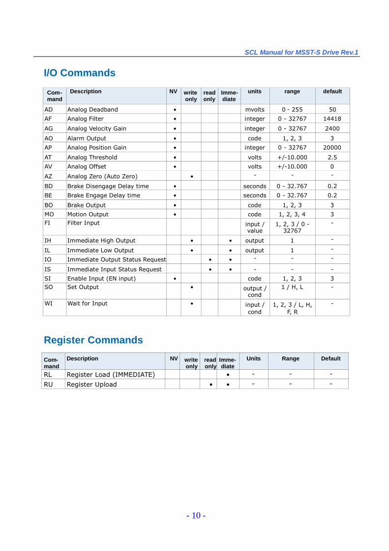
I/O Commands
Com-mand
Description NV writeonly
readonly
Imme-diate
units range default
AD Analog Deadband • mvolts 0 - 255 50
AF Analog Filter • integer 0 - 32767 14418
AG Analog Velocity Gain • integer 0 - 32767 2400
AO Alarm Output • code 1, 2, 3 3
AP Analog Position Gain • integer 0 - 32767 20000
AT Analog Threshold • volts +/-10.000 2.5
AV Analog Offset • volts +/-10.000 0
AZ Analog Zero (Auto Zero) • - - -
BD Brake Disengage Delay time • seconds 0 - 32.767 0.2
BE Brake Engage Delay time • seconds 0 - 32.767 0.2
BO Brake Output • code 1, 2, 3 3
MO Motion Output • code 1, 2, 3, 4 3FI Filter Input input /
value1, 2, 3 / 0 -
32767-
IH Immediate High Output • • output 1 -
IL Immediate Low Output • • output 1 -
IO Immediate Output Status Request • • - - -
IS Immediate Input Status Request • • - - -
SI Enable Input (EN input) • code 1, 2, 3 3SO Set Output • output /
cond1 / H, L -
WI Wait for Input • input /cond
1, 2, 3 / L, H,F, R
-
Register Commands
Com-mand
Description NV writeonly
readonly
Imme-diate
Units Range Default
RL Register Load (IMMEDIATE) • - - -
RU Register Upload • • - - -
SCL Manual for MSST-S Drive Rev.1
- 11 -
Command ListingThis section is an alphabetical listing of all the commands available with your drive. Each page in
this section contains the details of one available command. Below is a sample of what these pages looklike, with an explanation of the information you will find on each page.
Title - shows the command’s two-letter command code followed by the command’s name.
Description - an explanation of what the command does and how it works.
Affects - a summary of parameters or other commands the command affects.
See Also - related commands
Command Structure - shows the command’s syntax. The format for this line is always the two-lettercommand code, followed by the number of parameters it uses. Not all commands have parameters,some commands have optional parameters, and other commands always have a parameter. Optionalparameters are designated by { }, and required parameters are designated by ( ).
Details - shows the “Command Type”(buffered or immediate), the command’s “Usage”(Read Only,Read/Write, or Write Only), and whether the command is “Non-Volatile”or not. Non-Volatile commandsare saved when the Save (SA) command is sent. If the command transfers data to a register that isaccessible via the RL command, that register will be shown in “Register Access”. Also, the details of thecommand’s parameter(s) are shown. Parameter #1 or #2 gives a brief description of the parameter, “-units”shows how the parameter is interpreted by the drive, “- range”gives the acceptable range ofvalues for the parameter, and “- default”shows the default value of the parameter.
Examples - shows what to expect when you use this command. Under “Command”are the commandstrings you would send from a host controller. Note that <cr> is not shown after each command stringin these examples but is still necessary to terminate the string. Under “Drive Sends”are the responsesfrom the drive: no response from the drive is denoted by “-”, although if Ack/Nack is turned on therewill always be a response to every command sent. “Comments”gives additional information about theresults of the command string.
SCL Manual for MSST-S Drive Rev.1
- 12 -
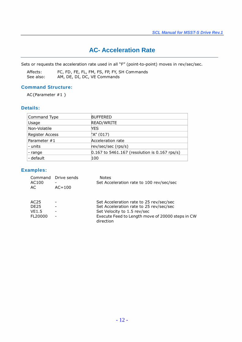
AC- Acceleration Rate
Sets or requests the acceleration rate used in all “F”(point-to-point) moves in rev/sec/sec.
Affects: FC, FD, FE, FL, FM, FS, FP, FY, SH CommandsSee also: AM, DE, DI, DC, VE Commands
Command Structure:
AC{Parameter #1 }
Details:
Command Type BUFFEREDUsage READ/WRITENon-Volatile YES
Register Access “A”(017)
Parameter #1 Acceleration rate- units rev/sec/sec (rps/s)
- range 0.167 to 5461.167 (resolution is 0.167 rps/s)- default 100
Examples:
Command Drive sends NotesAC100 - Set Acceleration rate to 100 rev/sec/secAC AC=100
AC25 - Set Acceleration rate to 25 rev/sec/secDE25 - Set Acceleration rate to 25 rev/sec/secVE1.5 - Set Velocity to 1.5 rev/secFL20000 - Execute Feed to Length move of 20000 steps in CW
direction

SCL Manual for MSST-S Drive Rev.1
- 13 -
AD - Analog Deadband
Sets or requests the analog deadband value in millivolts. The deadband value is the zone around the“zeroed”value of the analog input. This deadband defines the area of the analog input range that thedrive should interpret as “zero”. This zero point can be used as the zero velocity point in analogvelocity mode, or as the zero position point in analog position mode. The deadband is an absolutevalue that in usage is applied to either side of zero volts.
Affects:See also:
Analog inputCM command
Command Structure:AD{Parameter #1 }
Details:
Command Type BUFFEREDUsage READ/WRITE
Non-Volatile YES
Register Access None
Parameter #1 Analog deadband value
- units millivolts
- range 0 - 255
- default
Examples:
Command Drive sends NotesAD100 - Set analog dead band to 0.1 volts
SCL Manual for MSST-S Drive Rev.1
- 14 -
AF - Analog Filter
Applies a digital filter to the analog input. This is a simple single pole filter that rolls off the analoginput. The Filter value of the AF command is related to the desired value of the analog filter in Hz bythe following equation:
Filter value = 72090 / [(1400 /x) + 2.2 ]where x = desired value of the analog filter in Hz
Affects: Analog inputSee also: IA, CM commands
Command StructureAF{Parameter #1 }
Details:
Command Type BUFFEREDUsage READ/WRITE
Non-Volatile YES
Register Access None
Parameter #1 Filter value
- units integer (see formula above)
- range 0 - 32767* (0 disables the filter)
- default 14418 (500 Hz)
* An AF value of 28271 equates to 4000.425 Hz. Setting the AF command to anything higherthan 28271 has a negligible effect on the analog filter. In other words, the maximum value of thefilter is approximately 4000 Hz.
Examples:
Command Drive sends NotesAF5000 - Make the analog input bandwidth 114.585 Hz
AF AF=5000
SCL Manual for MSST-S Drive Rev.1
- 15 -
AG - Analog Velocity Gain
Sets or requests the gain value used in analog velocity (oscillator) mode. The gain value is used toestablish the relationship between the analog input and the motor speed. The units are 0.25 rpm.For example, if the gain is set to 2400, when 5 Volts is read at the analog input the motor will spinat 10 rps. TIP: To set the analog velocity gain to the desired value, multiply the desired motor speedin rps by 240, or the desired motor speed in rpm by 4.
Affects: Analog velocity modesSee also: CM command
Command Structure:AG{Parameter #1 }
Details:
Command Type BUFFEREDUsage READ/WRITE
Non-Volatile YES
Register Access None
Parameter #1 Analog velocity gain value- units 0.25 rpm
- range 0 - 32767
- default 2400 (10 rps)
Examples:
Command Drive sends NotesAG3000 - Set top speed of analog velocity mode to 12.5 rpsAG AG=3000

SCL Manual for MSST-S Drive Rev.1
- 16 -
AI- Alarm Reset Input (EN input)
Defines the EN input as an Alarm Reset Input.The EN input can be assigned to only one function in an application. If you want to use the EN input asan Alarm Reset input you can define it as such in two ways, with the ST Configurator software, or withthe AI command. AI takes no effect if the drive is set in Command Mode (CM) 13, 14, 17 or 18, becausethese modes use the EN input as a speed change input and take precedence over the AI command. Also,setting the SI command after setting the AI command reassigns the EN input to drive enable usage andturns off any alarm reset usage (AI3). In other words, the AI and SI commands, as well as CommandModes (CM) 13, 14, 17 and 18 each assign a usage to the EN input. Each of these must exclusively usethe EN input. Command Modes are most dominant and will continually prevent AI and SI from using theinput. AI and SI exclude each other by overwriting the usage of the EN input.There are three Alarm Reset states that can be defined with the AI command:
AI1: Alarm reset occurs when the EN input is closed (energized). This is an edge-triggeredevent. If the switch is closed when an alarm is activated no reset will occur. The input mustbe opened (de-energized) and then closed to reset the alarm.
AI2: Alarm reset occurs when the input is open (de-energized). This is an edge-triggeredevent. If the switch is open when an alarm is activated no reset will occur. The input mustbe closed (energized) and then opened to reset the alarm.
AI3: The EN Input is not used for Alarm Reset and can be used as a general purpose input. AIwill be automatically set to 3 if CM is set to 13, 14, 17, or 18, or if SI is set to 1 or 2 afterthe AI command is set.
Command Structure:AI {Parameter #1 }
Details:
Command Type BUFFEREDUsage READ/WRITE
Non-Volatile YES
Register Access NoneParameter #1 Usage State (see above for details)
- units integer number- range 1,2 or 3
- default 3
NOTE: When working with digital inputs and outputs in MSST-S drives it is important to remember the designationslow and high. If current is flowing into or out of an input or output, i.e. the circuit is energized, the logic state forthat input/output is defined as low or closed. If no current is flowing, i.e. the circuit is de-energized, or theinput/output is not connected, the logic state is high or open. A low state is represented by the “L”character inparameters of commands that affect inputs/outputs. For example, WI3L means “wait for input 3 (EN input) low”, andSO1L means “set output 1 low”. A high state is represented by the “H”character.
Examples:Command Drive sends NotesAI1 - Closing EN input resets all possible alarmsAI AI=1
SCL Manual for MSST-S Drive Rev.1
- 17 -
AL - Alarm Code
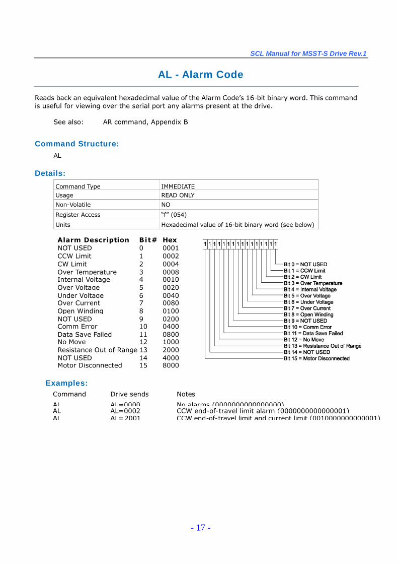
Reads back an equivalent hexadecimal value of the Alarm Code’s 16-bit binary word. This commandis useful for viewing over the serial port any alarms present at the drive.
See also: AR command, Appendix B
Command Structure:AL
Details:
Command Type IMMEDIATEUsage READ ONLY
Non-Volatile NO
Register Access “f”(054)
Units Hexadecimal value of 16-bit binary word (see below)
Alarm Description Bit# HexValueNOT USED 0 0001
CCW Limit 1 0002CW Limit 2 0004Over Temperature 3 0008Internal Voltage 4 0010Over Voltage 5 0020Under Voltage 6 0040Over Current 7 0080Open Winding 8 0100NOT USED 9 0200Comm Error 10 0400Data Save Failed 11 0800No Move 12 1000Resistance Out of Range 13 2000NOT USED 14 4000Motor Disconnected 15 8000
Examples:Command Drive sends Notes
AL AL=0000 No alarms (0000000000000000)AL AL=0002 CCW end-of-travel limit alarm (0000000000000001)AL AL=2001 CCW end-of-travel limit and current limit (0010000000000001)

SCL Manual for MSST-S Drive Rev.1
- 18 -
AM - Max Acceleration
Sets or requests the maximum acceleration/deceleration allowed when using analog velocity(oscillator) mode. Also sets the deceleration used when an end-of-travel limit is activated during anyof the “Feed”moves or when a Stop (ST) or Stop & Kill (SK) command is sent.
Affects: ST, SK commands. Analog velocity (oscillator) mode.See also: VM command
Command Structure:AM{Parameter #1}
Details:
Command Type BUFFEREDUsage READ/WRITE
Non-Volatile YES
Register Access None
Parameter #1 Maximum acceleration/deceleration
- units rev/sec/sec (rps/s)
- range 0.167 - 5461 .167 (resolution is 0.167 rps/s)
- default
Examples:Command Drive sends NotesAM2000 - Set maximum acceleration/deceleration rates to 2000 rev/sec/sec.AM AM=2000
SCL Manual for MSST-S Drive Rev.1
- 19 -
AO - Alarm Output
Defines the drive’s digital output as an Alarm Output.
The output of an MSST-S drive can be assigned to one of four functions: alarm output, brake output,motion output, or tach output. Each of these functions must exclusively use the output, so only onefunction is allowed. There are two ways to define the function of this output: via ST Configurator or viaSCL commands. To set the output as an alarm output, use the AO command and one of the codesbelow.
NOTE: Setting the AO command to 1 or 2 overrides previous assignments of this output’s function. Similarly, if youuse the BO or MO command to set the function of the output after setting the AO command to 1 or 2, usage of theoutput will be reassigned and AO will be automatically set to 3.
There are three Alarm Output states that can be defined with the AO command:
AO1: Output is closed (energized) when an alarm is present.AO2: Output is open (de-energized) when an alarm is present.AO3: Output is not used as an Alarm Output and can be used for another automatic output
function or as a general purpose output.
Affects: Function of digital outputSee also: AI, SI, BO, and MO commands
Command Structure:AO{Parameter #1 }
Details:
Command Type BUFFEREDUsage READ/WRITE
Non-Volatile YES
Register Access None
Parameter #1 Output State (see above)
- units integer code
- range 1, 2 or 3
- default 3
NOTE: When working with digital inputs and outputs in MSST-S drives it is important to remember the designationslow and high. If current is flowing into or out of an input or output, i.e. the circuit is energized, the logic state for thatinput/output is defined as low or closed. If no current is flowing, i.e. the circuit is de-energized, or the input/output isnot connected, the logic state is high or open. A low state is represented by the “L”character in parameters ofcommands that affect inputs/outputs. For example, WI3L means “wait for input 3 (EN input) low”, and SO1L means“set output 1 low”. A high state is represented by the “H”character.
Examples:Command Drive sends NotesAO1 - Output will be closed when an alarm or fault occursAO AO=1
SCL Manual for MSST-S Drive Rev.1
- 20 -
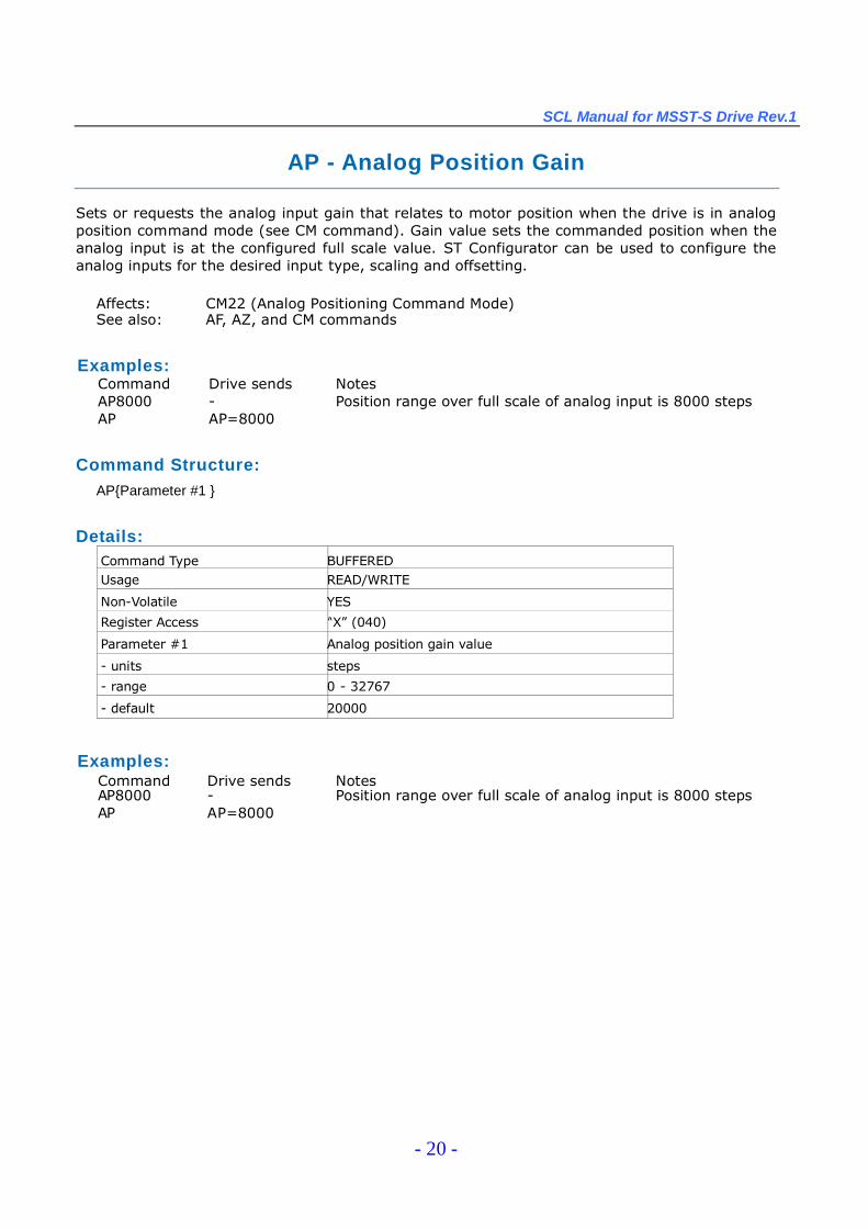
AP - Analog Position Gain
Sets or requests the analog input gain that relates to motor position when the drive is in analogposition command mode (see CM command). Gain value sets the commanded position when theanalog input is at the configured full scale value. ST Configurator can be used to configure theanalog inputs for the desired input type, scaling and offsetting.
Affects: CM22 (Analog Positioning Command Mode)See also: AF, AZ, and CM commands
Command Structure:AP{Parameter #1 }
Details:Command Type BUFFEREDUsage READ/WRITE
Non-Volatile YES
Register Access “X”(040)
Parameter #1 Analog position gain value
- units steps
- range 0 - 32767
- default 20000
Examples:Command Drive sends NotesAP8000 - Position range over full scale of analog input is 8000 stepsAP AP=8000
Examples:Command Drive sends NotesAP8000 - Position range over full scale of analog input is 8000 stepsAP AP=8000
SCL Manual for MSST-S Drive Rev.1
- 21 -
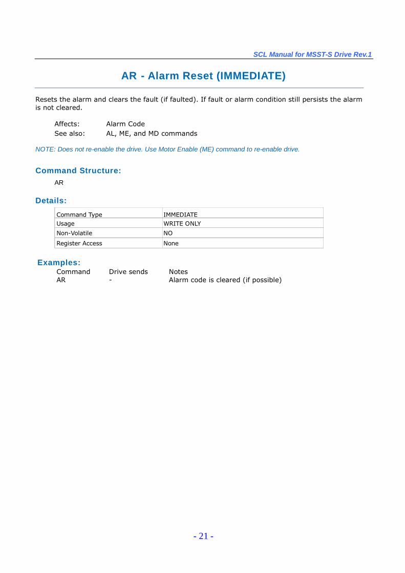
AR - Alarm Reset (IMMEDIATE)
Resets the alarm and clears the fault (if faulted). If fault or alarm condition still persists the alarmis not cleared.
Affects: Alarm CodeSee also: AL, ME, and MD commands
NOTE: Does not re-enable the drive. Use Motor Enable (ME) command to re-enable drive.
Command Structure:AR
Details:
Command Type IMMEDIATEUsage WRITE ONLY
Non-Volatile NO
Register Access None
Examples:Command Drive sends NotesAR - Alarm code is cleared (if possible)
SCL Manual for MSST-S Drive Rev.1
- 22 -
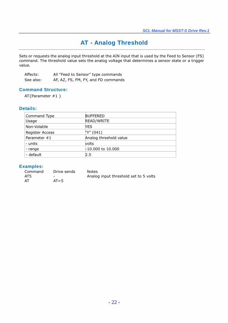
AT - Analog Threshold
Sets or requests the analog input threshold at the AIN input that is used by the Feed to Sensor (FS)command. The threshold value sets the analog voltage that determines a sensor state or a triggervalue.
Affects: All “Feed to Sensor”type commandsSee also: AF, AZ, FS, FM, FY, and FD commands
Command Structure:AT{Parameter #1 }
Details:
Command Type BUFFEREDUsage READ/WRITE
Non-Volatile YES
Register Access “Y”(041)Parameter #1 Analog threshold value
- units volts- range -10.000 to 10.000
- default 2.5
Examples:Command Drive sends NotesAT5 - Analog input threshold set to 5 voltsAT AT=5
SCL Manual for MSST-S Drive Rev.1
- 23 -
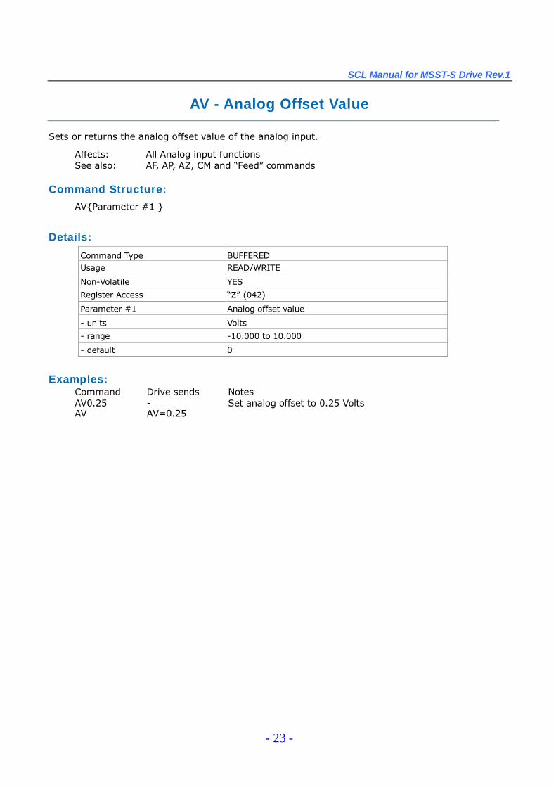
AV - Analog Offset Value
Sets or returns the analog offset value of the analog input.
Affects: All Analog input functionsSee also: AF, AP, AZ, CM and “Feed”commands
Command Structure:
AV{Parameter #1 }
Details:
Command Type BUFFEREDUsage READ/WRITE
Non-Volatile YES
Register Access “Z”(042)
Parameter #1 Analog offset value
- units Volts
- range -10.000 to 10.000
- default 0
Examples:Command Drive sends NotesAV0.25 - Set analog offset to 0.25 VoltsAV AV=0.25
SCL Manual for MSST-S Drive Rev.1
- 24 -
AX - Alarm Reset (BUFFERED)
Resets a drive fault and clears the alarm code. This command is the same as the AR command butis a buffered command rather than an immediate command.
NOTE: Does not re-enable the drive. Use Motor Enable (ME) command to re-enable drive.
Affects: Alarm CodeSee also: ME, AR Commands
Command Structure:
AX
Details:
Command Type BUFFEREDUsage WRITE ONLY
Non-Volatile NO
Register Access None
Examples:Command Drive sends NotesAX - Reset drive fault and clear alarm code

SCL Manual for MSST-S Drive Rev.1
- 25 -
AZ - Analog Zero
Activates the analog “auto offset”algorithm. This algorithm can also be accessed in ST Con-figurator. It is useful in defining the current voltage present at the analog input as the zero point oroffset.
Affects: All Analog input functionsSee also: AF, AP, AV, CM and “Feed”commands
Command Structure:AZ
Details:
Command Type BUFFEREDUsage WRITE ONLY
Non-Volatile NO
Register Access None
Examples:Command Drive sends NotesAZ - Start analog auto offset algorithm
Examples: Apply 1 VDC across the AIN(+) and GND(-) terminals of the drive. Then send the AZcommand to the drive. Next apply 4 VDC across the AIN and GND terminals. Send the IA commandand the response should be very close to IA=3.00.
SCL Manual for MSST-S Drive Rev.1
- 26 -
BD - Brake Disengage Delay
This command only takes effect if the BO command is set to 1 or 2. After a drive is enabled this is thetime value that may delay a move waiting for the brake to disengage. When beginning a move thedelay value must expire before a move can take place. The delay timer begins counting downimmediately after the drive is enabled and the brake output is set. The BD command sets a time inmilliseconds that a move may be delayed.
Affects: All “Feed”and Jog commands.See also: BE and BO commands
Command Structure:
BD{Parameter #1 }
Details:
Command Type BUFFEREDUsage READ/WRITE
Non-Volatile YES
Register Access None
Parameter #1 Delay time
- units seconds
- range 0 - 32.767
- default 0.2
Examples:Command Drive sends NotesBD0.2 - Sets brake disengage delay to 200 msBD BD=0.2

SCL Manual for MSST-S Drive Rev.1
- 27 -
BE - Brake Engage Delay
This command only takes effect if the BO command is set to 1 or 2. After a drive is commanded tobe disabled, this is the time value that delays the actual disabling of the driver output. When usingthe digital output as a brake output (see BO command) the output is activated immediately with thedisable command, then the drive the waits the delay time before turning off the driver outputs.
Affects: All “Feed”and Jog commandsSee also: BD and BO commands
Command Structure:BE{Parameter #1 }
Details:
Command Type BUFFEREDUsage READ/WRITE
Non-Volatile YES
Register Access None
Parameter #1 Delay time
- units seconds
- range 0 - 32.767
- default 0.2
Examples:Command Drive sends NotesBE0.25 - Sets brake engage delay to 250 msBE BE=0.25
SCL Manual for MSST-S Drive Rev.1
- 28 -
BO - Brake Output
Defines the drive’s digital output as a Brake Output.
The output of an MSST-S drive can be assigned to one of four functions: alarm output, brake output,motion output, or tach output. Each of these functions must exclusively use the output, so only onefunction is allowed. There are two ways to define the function of this output: via ST Configurator or viaSCL commands. To set the output as a brake output, use the BO command and one of the codes below.
NOTE: Setting the BO command to 1 or 2 overrides previous assignments of this output’s function. Similarly, ifyou use the AO or MO command to set the function of the output after setting the BO command to 1 or 2, usageof the output wil be reassigned and BO wil be automaticaly set to 3.
There are three Brake Output states that can be defined with the BO command:
BO1: Output is closed (energized) when the drive is enabled, and open when the drives is disabled.BO2: Output is open(de-energized) when the drive is enabled, and closed when the drive is
disabled.BO3: Output is not used as an Brake Output and can be used for another automatic output function
or as a general purpose output.
Affects: Function of digital outputSee also: AI, AO, ME, MD, MO, SI commands
Command Structure:BO{Parameter #1 }
Details:
Command Type BUFFEREDUsage READ/WRITE
Non-Volatile YES
Register Access None
Parameter #1 Output state (see above)
- units integer number
- range 1, 2 or 3
- default 3
NOTE: When working with digital inputs and outputs in MSST-S drives it is important to remember the designationslow and high. If current is flowing into or out of an input or output, i.e. the circuit is energized, the logic state for thatinput/output is defined as low or closed. If no current is flowing, i.e. the circuit is de-energized, or the input/output isnot connected, the logic state is high or open. A low state is represented by the “L”character in parameters ofcommands that affect inputs/outputs. For example, WI3L means “wait for input 3 (EN input) low”, and SO1L means“set output 1 low”. A high state is represented by the “H”character.
Examples:Command Drive sends NotesBO1 - Output will be closed when drive is enabledBO BO= 1
SCL Manual for MSST-S Drive Rev.1
- 29 -
BR - Baud Rate
Sets or requests the bit rate (baud) for serial communications.
At power up the drive defaults to 9600 baud. If a host system is not detected after 1 second and thedrive is configured for SCL mode the drive will set the baud rate according to the value stored in thebaud rate NV parameter. A host system can set the baud rate at anytime using this command.
NOTE: Setting the value takes effect immediately.
Affects: Serial communications with the hostSee also: TD, PR commands
Command Structure:BR{Parameter #1 }
Details:
Command Type BUFFEREDUsage READ/WRITE
Non-Volatile YES
Register Access None
Parameter #1 Baud rate (see above)
- units integer code- range 1 = 9600
2 = 192003 = 384004 = 576005 = 115200
- default 1
Examples:Command Drive sends NotesBR2 - Baud rate is immediately set to 19200 bpsBR BR=2

SCL Manual for MSST-S Drive Rev.1
- 30 -
BS - Buffer Status
Requests from the drive the number of available command locations in the command buffer. Thistechnique simplifies sending commands by eliminating the need to calculate if there is enough spacein the buffer for additional commands. If the drive responds with at least a “1”, a command can besent.
If a drive responds to the BS command with “63”, the buffer is empty. If a “0”is returned the bufferis full and no more buffered commands can be accepted.
Command Structure:BS
Details:
Command Type IMMEDIATEUsage READ ONLY
Non-Volatile NO
Register Access None
Units Empty command spaces in buffer
Examples:CommandBS
Drive sendsBS=20
NotesThere is room in the buffer for 20 more commands

SCL Manual for MSST-S Drive Rev.1
- 31 -
CC - Change Current
Sets or requests the current setting of drive.
Affects: All “Feed”commands, CJ, SH, WI (jogging) and Torque ModeSee also: PC command
Command Structure:
CC{Parameter #1 }
Details:
Command Type BUFFEREDUsage READ/WRITE
Non-Volatile YES
Register Access “N”(030)
Parameter #1 Motor current
- units amps- range 0 - 5.0 (MSST5-S)
0 - 10.0 (MMST10-S)
Examples:Command Drive sends NotesCC4.50 - Set current to 4.5 ampsCC CC=4.5
SCL Manual for MSST-S Drive Rev.1
- 32 -
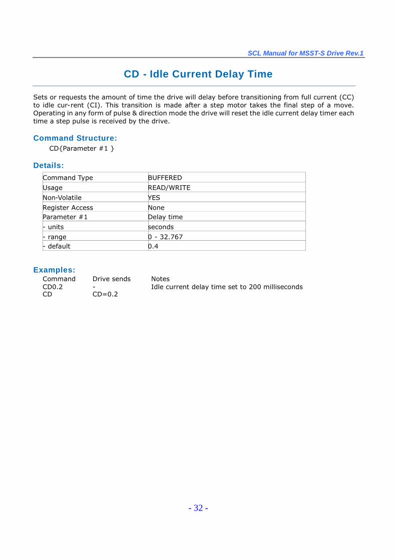
CD - Idle Current Delay Time
Sets or requests the amount of time the drive will delay before transitioning from full current (CC)to idle cur-rent (CI). This transition is made after a step motor takes the final step of a move.Operating in any form of pulse & direction mode the drive will reset the idle current delay timer eachtime a step pulse is received by the drive.
Command Structure:CD{Parameter #1 }
Details:
Command Type BUFFERED
Usage READ/WRITE
Non-Volatile YES
Register Access NoneParameter #1 Delay time
- units seconds
- range 0 - 32.767- default 0.4
Examples:Command Drive sends NotesCD0.2 - Idle current delay time set to 200 millisecondsCD CD=0.2
SCL Manual for MSST-S Drive Rev.1
- 33 -
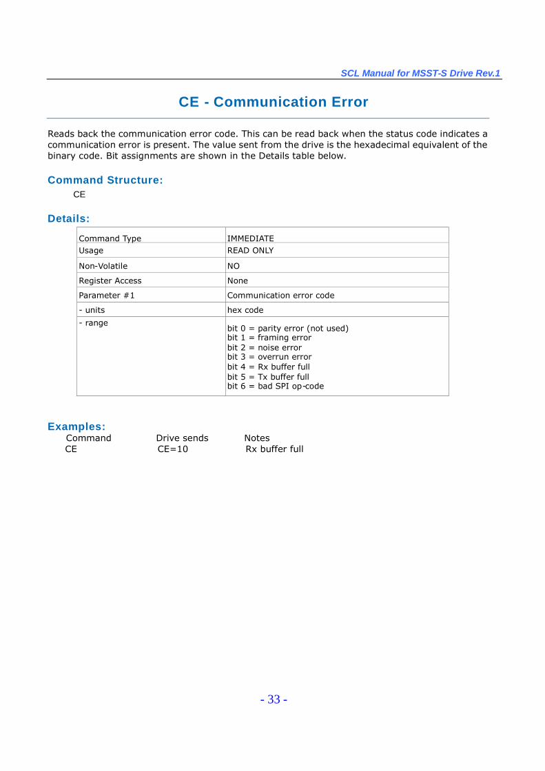
CE - Communication Error
Reads back the communication error code. This can be read back when the status code indicates acommunication error is present. The value sent from the drive is the hexadecimal equivalent of thebinary code. Bit assignments are shown in the Details table below.
Command Structure:CE
Details:
Command Type IMMEDIATEUsage READ ONLY
Non-Volatile NO
Register Access None
Parameter #1 Communication error code
- units hex code
- rangebit 0 = parity error (not used)bit 1 = framing errorbit 2 = noise errorbit 3 = overrun errorbit 4 = Rx buffer fullbit 5 = Tx buffer fullbit 6 = bad SPI op-code
Examples:Command Drive sends NotesCE CE=10 Rx buffer full

SCL Manual for MSST-S Drive Rev.1
- 34 -
CF - Anti-Resonance Filter Frequency
Sets or requests the anti-resonance filter frequency setting. This setting is in Hz and works inconjunction with the anti-resonance filter gain setting (CG) to cancel instabilities due to mid-bandresonance.
NOTE: We strongly suggest using ST Configurator to set this value by entering as accurate a load inertiavalue as possible in the motor settings window.
Affects: Mid-range performance of step motorsSee also: CG command
Command Structure:CF{Parameter #1 }
Details:
Command Type BUFFEREDUsage READ/WRITE
Non-Volatile YESRegister Access None
Parameter #1 Filter frequency- units Hz
- range 0 - 2000
- default 241
Examples:Command Drive sends NotesCF1400 - Set anti-resonance filter frequency to 1400 HzCF CF=1400

SCL Manual for MSST-S Drive Rev.1
- 35 -
CG - Anti-Resonance Filter Gain
Sets or requests the anti-resonance filter gain setting. This setting works in conjunction with theanti-resonance filter frequency setting (CF) to cancel instabilities due to mid-band resonance.
NOTE: We strongly suggest using ST Configurator to set this value by entering as accurate a load inertia valueas possible in the motor settings window.
Affects: Mid-range performance of step motorsSee also: CF command
Command Structure:CG{Parameter #1 }
Details:
Command Type BUFFEREDUsage READ/WRITE
Non-Volatile YES
Register Access None
Parameter #1 Filter gain
- units integer number
- range 0 - 32767
- default 12000
Examples:Command Drive sends NotesCG800 - Set anti-resonance filter gain to 800CG CG=800
SCL Manual for MSST-S Drive Rev.1
- 36 -
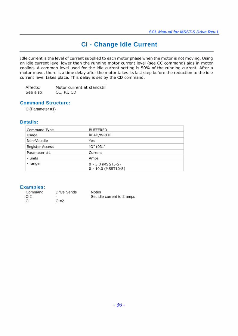
CI - Change Idle Current
Idle current is the level of current supplied to each motor phase when the motor is not moving. Usingan idle current level lower than the running motor current level (see CC command) aids in motorcooling. A common level used for the idle current setting is 50% of the running current. After amotor move, there is a time delay after the motor takes its last step before the reduction to the idlecurrent level takes place. This delay is set by the CD command.
Affects: Motor current at standstillSee also: CC, PI, CD
Command Structure:CI{Parameter #1}
Details:
Command Type BUFFEREDUsage READ/WRITE
Non-Volatile Yes
Register Access “O”(031)
Parameter #1 Current
- units Amps- range 0 - 5.0 (MSST5-S)
0 - 10.0 (MSST10-S)
Examples:Command Drive Sends NotesCI2 - Set idle current to 2 ampsCI CI=2
SCL Manual for MSST-S Drive Rev.1
- 37 -
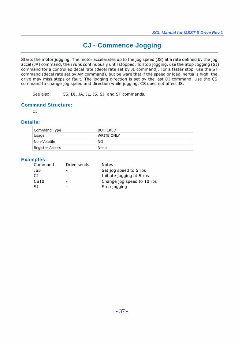
CJ - Commence Jogging
Starts the motor jogging. The motor accelerates up to the jog speed (JS) at a rate defined by the jogaccel (JA) command, then runs continuously until stopped. To stop jogging, use the Stop Jogging (SJ)command for a controlled decel rate (decel rate set by JL command). For a faster stop, use the STcommand (decel rate set by AM command), but be ware that if the speed or load inertia is high, thedrive may miss steps or fault. The jogging direction is set by the last DI command. Use the CScommand to change jog speed and direction while jogging. CS does not affect JS.
See also: CS, DI, JA, JL, JS, SJ, and ST commands.
Command Structure:CJ
Details:
Command Type BUFFEREDUsage WRITE ONLY
Non-Volatile NO
Register Access None
Examples:Command Drive sends NotesJS5 - Set jog speed to 5 rpsCJ - Initiate jogging at 5 rpsCS10 - Change jog speed to 10 rpsSJ - Stop jogging
SCL Manual for MSST-S Drive Rev.1
- 38 -
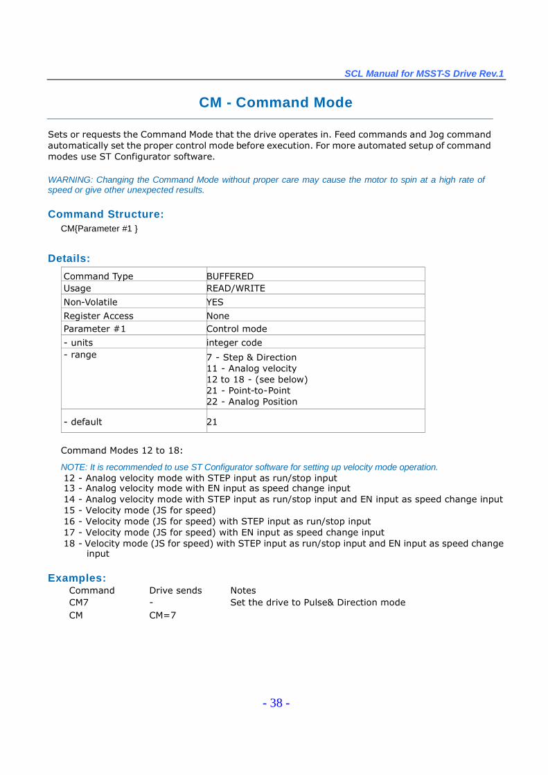
CM - Command Mode
Sets or requests the Command Mode that the drive operates in. Feed commands and Jog commandautomatically set the proper control mode before execution. For more automated setup of commandmodes use ST Configurator software.
WARNING: Changing the Command Mode without proper care may cause the motor to spin at a high rate ofspeed or give other unexpected results.
Command Structure:CM{Parameter #1 }
Details:
Command Type BUFFEREDUsage READ/WRITE
Non-Volatile YES
Register Access NoneParameter #1 Control mode
- units integer code- range 7 - Step & Direction
11 - Analog velocity12 to 18 - (see below)21 - Point-to-Point22 - Analog Position
- default 21
Command Modes 12 to 18:
NOTE: It is recommended to use ST Configurator software for setting up velocity mode operation.12 - Analog velocity mode with STEP input as run/stop input13 - Analog velocity mode with EN input as speed change input14 - Analog velocity mode with STEP input as run/stop input and EN input as speed change input15 - Velocity mode (JS for speed)16 - Velocity mode (JS for speed) with STEP input as run/stop input17 - Velocity mode (JS for speed) with EN input as speed change input18 - Velocity mode (JS for speed) with STEP input as run/stop input and EN input as speed change
input
Examples:Command Drive sends NotesCM7 - Set the drive to Pulse& Direction modeCM CM=7

SCL Manual for MSST-S Drive Rev.1
- 39 -
CS - Change Speed
Sets or requests the jog speed in rev/sec while jogging. When Jogging using the CJ command thejog speed can be changed dynamically by using this command. The value of CS can be positive ornegative allowing the direction of jogging to be changed also. Ramping between speeds whilejogging is controlled by the JA and JL commands. Changing CS does not change either JS or DI.
Affects: Jog speed while joggingSee also: CJ and JS commands
Command Structure:CS{Parameter #1 }
Details:
Command Type IMMEDIATE
Usage READ/WRITE
Non-Volatile NO
Register Access “J”(026)
Parameter #1 Jog Speed
- units rev/sec
- range -133.3333 to 133.3333sign determines direction: “-“for CCW, no sign for CW
Examples:CommandCS2.5CSCS-5
Drive sends Notes- Set jog speed to CW at 2.5 rev/secCS=2.5 Displays current Jog speed- Set jog speed to CCW at 5 rev/sec

SCL Manual for MSST-S Drive Rev.1
- 40 -
CT –Continue
Resume execution of buffered commands after a PS command has been sent. The Pause (PS)command allows you to pause execution of commands in the command buffer. After sending the PScommand, subsequent commands are buffered in the command buffer until either a CT command issent, at which time the buffered commands will execute in the order they were received, or until thecommand buffer is full.
See also: PS, ST, and SK commands
Command Structure:CT
Details:
Command Type IMMEDIATEUsage WRITE ONLY
Non-Volatile NO
Register Access None
Examples:Command Drive sends NotesCT - Resumes execution of a paused command buffer
SCL Manual for MSST-S Drive Rev.1
- 41 -
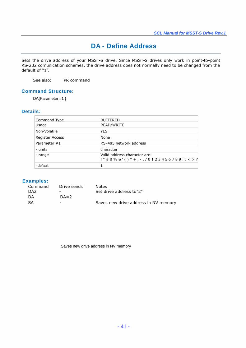
DA - Define Address
Sets the drive address of your MSST-S drive. Since MSST-S drives only work in point-to-pointRS-232 comunication schemes, the drive address does not normally need to be changed from thedefault of “1”.
See also: PR command
Command Structure:DA{Parameter #1 }
Details:
Command Type BUFFEREDUsage READ/WRITE
Non-Volatile YES
Register Access None
Parameter #1 RS-485 network address
- units character- range Valid address character are:
! “# $ % & ‘( ) * + , - . / 0 1 2 3 4 5 6 7 8 9 : ; < > ?@- default 1
Saves new drive address in NV memory
Examples:Command Drive sends NotesDA2 - Set drive address to”2”DA DA=2SA - Saves new drive address in NV memory

SCL Manual for MSST-S Drive Rev.1
- 42 -
DC - Change Distance
Sets or requests the “change distance”or offset distance in steps. The change distance is used byvarious move commands to define more than one distance parameter. All move commands use theDI command at some level, and many require DC as well. Examples are FC, FM, FO, and FY. Themoves executed by these commands change their behavior after the change distance (DC) has beentraveled. For example, FM is similar to FS, but in an FM move the sensor input is ignored until themotor has moved the number of steps set by DC. This is useful for masking unwanted switch orsensor triggers. Since DI sets move direction (CW or CCW), the sign of DC is ignored.
Affects: FC, FY, FO, and FM commandsSee also: VC command
Command Structure:DC{Parameter #1 }
Details:
Command Type BUFFEREDUsage READ/WRITE
Non-Volatile YES
Register Access “C”(019)
Parameter #1 distance
- units steps
- range 0 to 2,147,483,647
- default 0
Examples:Command Drive sends NotesDC80000 - Set change distance to 80000 countsDC DC=80000
DI-100000 - Set overall distance to 100000 counts in CCWdirection
DC50000 - Set change distance to 50000 countsVE5 - Set velocity to 5 rev/secVC2 - Set change velocity to 2 rev/secFC - Initiate FC command
SCL Manual for MSST-S Drive Rev.1
- 43 -
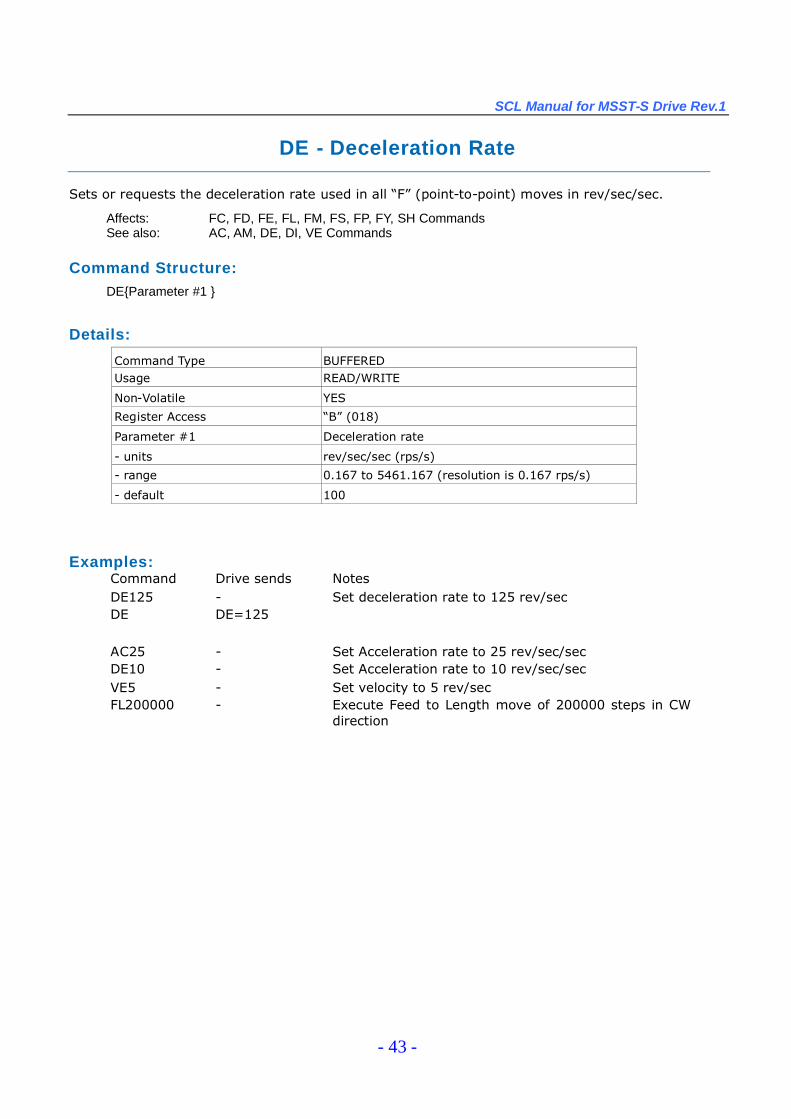
DE - Deceleration Rate
Sets or requests the deceleration rate used in all “F”(point-to-point) moves in rev/sec/sec.
Affects: FC, FD, FE, FL, FM, FS, FP, FY, SH CommandsSee also: AC, AM, DE, DI, VE Commands
Command Structure:DE{Parameter #1 }
Details:
Command Type BUFFEREDUsage READ/WRITE
Non-Volatile YES
Register Access “B”(018)
Parameter #1 Deceleration rate
- units rev/sec/sec (rps/s)
- range 0.167 to 5461.167 (resolution is 0.167 rps/s)
- default 100
Examples:Command Drive sends NotesDE125 - Set deceleration rate to 125 rev/secDE DE=125
AC25 - Set Acceleration rate to 25 rev/sec/secDE10 - Set Acceleration rate to 10 rev/sec/secVE5 - Set velocity to 5 rev/secFL200000 - Execute Feed to Length move of 200000 steps in CW
direction
SCL Manual for MSST-S Drive Rev.1
- 44 -
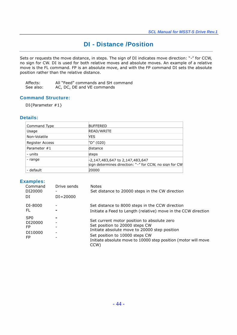
DI - Distance /Position
Sets or requests the move distance, in steps. The sign of DI indicates move direction: “-”for CCW,no sign for CW. DI is used for both relative moves and absolute moves. An example of a relativemove is the FL command. FP is an absolute move, and with the FP command DI sets the absoluteposition rather than the relative distance.
Affects: All “Feed”commands and SH commandSee also: AC, DC, DE and VE commands
Command Structure:
DI{Parameter #1}
Details:
Command Type BUFFEREDUsage READ/WRITE
Non-Volatile YES
Register Access “D”(020)
Parameter #1 distance
- units steps- range -2,147,483,647 to 2,147,483,647
sign determines direction: “-”for CCW, no sign for CW
- default 20000
Examples:Command Drive sends NotesDI20000 - Set distance to 20000 steps in the CW directionDI DI=20000
DI-8000 -FL -
SP0 -DI20000 -FP -DI10000 -FP -
Set distance to 8000 steps in the CCW directionInitiate a Feed to Length (relative) move in the CCW direction
Set current motor position to absolute zeroSet position to 20000 steps CWInitiate absolute move to 20000 step positionSet position to 10000 steps CWInitiate absolute move to 10000 step position (motor will moveCCW)
SCL Manual for MSST-S Drive Rev.1
- 45 -
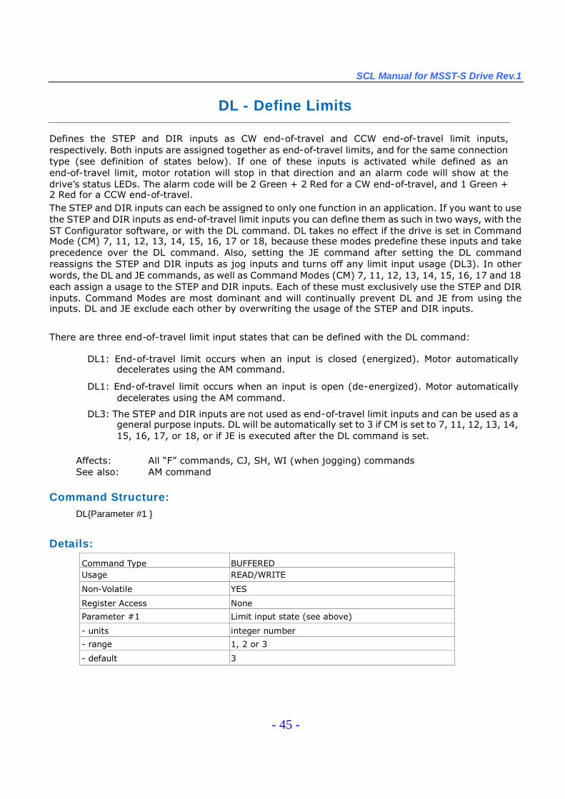
DL - Define Limits
Defines the STEP and DIR inputs as CW end-of-travel and CCW end-of-travel limit inputs,respectively. Both inputs are assigned together as end-of-travel limits, and for the same connectiontype (see definition of states below). If one of these inputs is activated while defined as anend-of-travel limit, motor rotation will stop in that direction and an alarm code will show at thedrive’s status LEDs. The alarm code will be 2 Green + 2 Red for a CW end-of-travel, and 1 Green +2 Red for a CCW end-of-travel.The STEP and DIR inputs can each be assigned to only one function in an application. If you want to usethe STEP and DIR inputs as end-of-travel limit inputs you can define them as such in two ways, with theST Configurator software, or with the DL command. DL takes no effect if the drive is set in CommandMode (CM) 7, 11, 12, 13, 14, 15, 16, 17 or 18, because these modes predefine these inputs and takeprecedence over the DL command. Also, setting the JE command after setting the DL commandreassigns the STEP and DIR inputs as jog inputs and turns off any limit input usage (DL3). In otherwords, the DL and JE commands, as well as Command Modes (CM) 7, 11, 12, 13, 14, 15, 16, 17 and 18each assign a usage to the STEP and DIR inputs. Each of these must exclusively use the STEP and DIRinputs. Command Modes are most dominant and will continually prevent DL and JE from using theinputs. DL and JE exclude each other by overwriting the usage of the STEP and DIR inputs.
There are three end-of-travel limit input states that can be defined with the DL command:
DL1: End-of-travel limit occurs when an input is closed (energized). Motor automaticallydecelerates using the AM command.
DL1: End-of-travel limit occurs when an input is open (de-energized). Motor automaticallydecelerates using the AM command.
DL3: The STEP and DIR inputs are not used as end-of-travel limit inputs and can be used as ageneral purpose inputs. DL will be automatically set to 3 if CM is set to 7, 11, 12, 13, 14,15, 16, 17, or 18, or if JE is executed after the DL command is set.
Affects: All “F”commands, CJ, SH, WI (when jogging) commandsSee also: AM command
Command Structure:DL{Parameter #1 }
Details:
Command Type BUFFEREDUsage READ/WRITE
Non-Volatile YES
Register Access None
Parameter #1 Limit input state (see above)
- units integer number
- range 1, 2 or 3
- default 3
SCL Manual for MSST-S Drive Rev.1
- 46 -
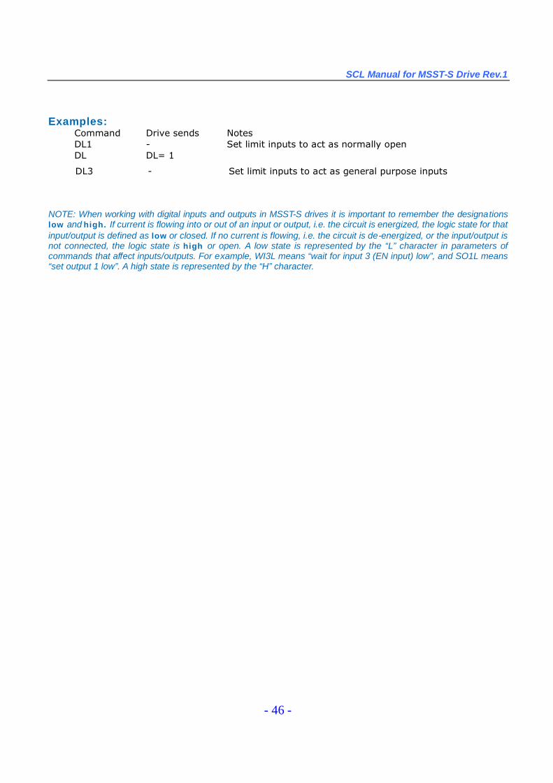
NOTE: When working with digital inputs and outputs in MSST-S drives it is important to remember the designationslow and high. If current is flowing into or out of an input or output, i.e. the circuit is energized, the logic state for thatinput/output is defined as low or closed. If no current is flowing, i.e. the circuit is de-energized, or the input/output isnot connected, the logic state is high or open. A low state is represented by the “L”character in parameters ofcommands that affect inputs/outputs. For example, WI3L means “wait for input 3 (EN input) low”, and SO1L means“set output 1 low”. A high state is represented by the “H”character.
Examples:Command Drive sends NotesDL1 - Set limit inputs to act as normally openDL DL= 1
DL3 - Set limit inputs to act as general purpose inputs
SCL Manual for MSST-S Drive Rev.1
- 47 -
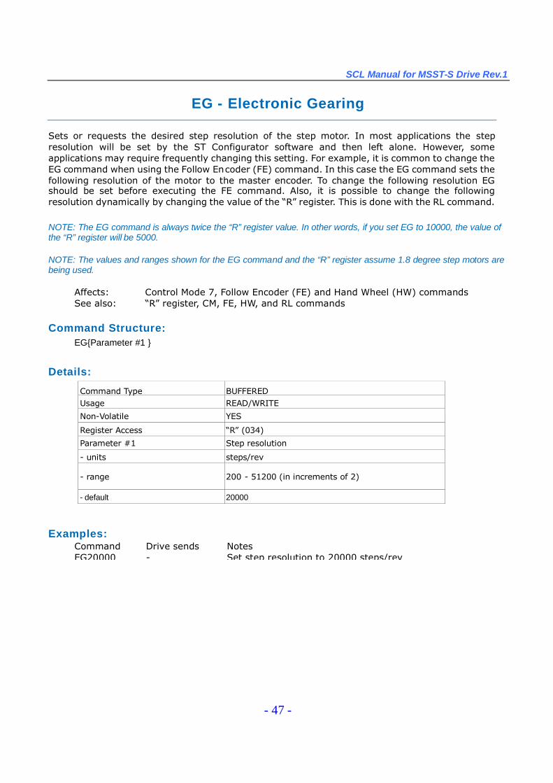
EG - Electronic Gearing
Sets or requests the desired step resolution of the step motor. In most applications the stepresolution will be set by the ST Configurator software and then left alone. However, someapplications may require frequently changing this setting. For example, it is common to change theEG command when using the Follow Encoder (FE) command. In this case the EG command sets thefollowing resolution of the motor to the master encoder. To change the following resolution EGshould be set before executing the FE command. Also, it is possible to change the followingresolution dynamically by changing the value of the “R”register. This is done with the RL command.
NOTE: The EG command is always twice the “R”register value. In other words, if you set EG to 10000, the value ofthe “R”register will be 5000.
NOTE: The values and ranges shown for the EG command and the “R”register assume 1.8 degree step motors arebeing used.
Affects: Control Mode 7, Follow Encoder (FE) and Hand Wheel (HW) commandsSee also: “R”register, CM, FE, HW, and RL commands
Command Structure:EG{Parameter #1 }
Details:
Command Type BUFFEREDUsage READ/WRITE
Non-Volatile YES
Register Access “R”(034)
Parameter #1 Step resolution
- units steps/rev
- range 200 - 51200 (in increments of 2)
- default 20000
Examples:Command Drive sends NotesEG20000 - Set step resolution to 20000 steps/rev

SCL Manual for MSST-S Drive Rev.1
- 48 -
FC - Feed to Length with Speed Change
Executes a Feed to Length (relative move) with a speed change. Overall move distance and directioncome from the last DI command. Accel and decel are from AC and DE commands. Initial speed is VE.After the motor has moved DC counts, the speed is reduced to VC.
NOTE: If DC is greater than DI minus the distance required to decelerate the motor (affected by DE and VE), nospeed change wil result.
See also: VC and DC commands
Command Structure:FC
Details:
Command Type BUFFEREDUsage WRITE ONLY
Non-Volatile NO
Register Access None
Examples:Command Drive sends NotesD150000 - Set overall distance to 50000 stepsVE5 - Set initial velocity to 5 rev/secDC40000 - Set change distance to 40000 stepsVC0.5 - Set change velocity to 0.5 rev/secFC - Initiate move
SCL Manual for MSST-S Drive Rev.1
- 49 -
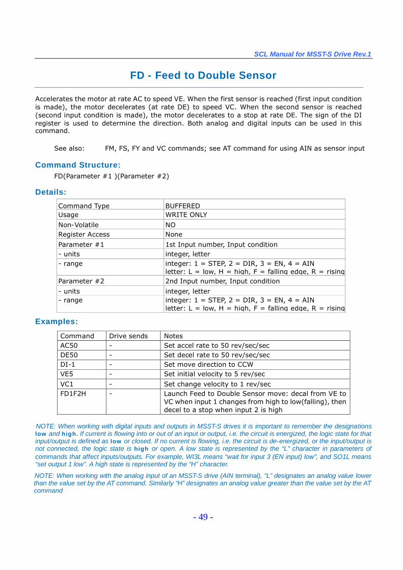
FD - Feed to Double Sensor
Accelerates the motor at rate AC to speed VE. When the first sensor is reached (first input conditionis made), the motor decelerates (at rate DE) to speed VC. When the second sensor is reached(second input condition is made), the motor decelerates to a stop at rate DE. The sign of the DIregister is used to determine the direction. Both analog and digital inputs can be used in thiscommand.
See also: FM, FS, FY and VC commands; see AT command for using AIN as sensor input
Command Structure:FD(Parameter #1 )(Parameter #2)
Details:
Command Type BUFFEREDUsage WRITE ONLY
Non-Volatile NORegister Access None
Parameter #1 1st Input number, Input condition- units integer, letter- range integer: 1 = STEP, 2 = DIR, 3 = EN, 4 = AIN
letter: L = low, H = high, F = falling edge, R = risingedgeParameter #2 2nd Input number, Input condition
- units integer, letter- range integer: 1 = STEP, 2 = DIR, 3 = EN, 4 = AIN
letter: L = low, H = high, F = falling edge, R = risingedge
Examples:
NOTE: When working with digital inputs and outputs in MSST-S drives it is important to remember the designationslow and high. If current is flowing into or out of an input or output, i.e. the circuit is energized, the logic state for thatinput/output is defined as low or closed. If no current is flowing, i.e. the circuit is de-energized, or the input/output isnot connected, the logic state is high or open. A low state is represented by the “L”character in parameters ofcommands that affect inputs/outputs. For example, WI3L means “wait for input 3 (EN input) low”, and SO1L means“set output 1 low”. A high state is represented by the “H”character.
NOTE: When working with the analog input of an MSST-S drive (AIN terminal), “L”designates an analog value lowerthan the value set by the AT command. Similarly “H”designates an analog value greater than the value set by the ATcommand
Command Drive sends NotesAC50 - Set accel rate to 50 rev/sec/secDE50 - Set decel rate to 50 rev/sec/secDI-1 - Set move direction to CCWVE5 - Set initial velocity to 5 rev/sec
VC1 - Set change velocity to 1 rev/secFD1F2H - Launch Feed to Double Sensor move: decal from VE to
VC when input 1 changes from high to low(falling), thendecel to a stop when input 2 is high
SCL Manual for MSST-S Drive Rev.1
- 50 -
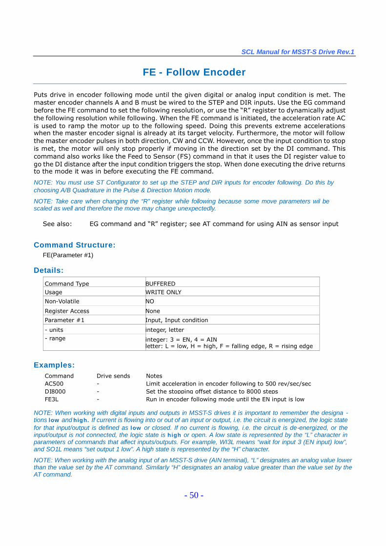
FE - Follow Encoder
Puts drive in encoder following mode until the given digital or analog input condition is met. Themaster encoder channels A and B must be wired to the STEP and DIR inputs. Use the EG commandbefore the FE command to set the following resolution, or use the “R”register to dynamically adjustthe following resolution while following. When the FE command is initiated, the acceleration rate ACis used to ramp the motor up to the following speed. Doing this prevents extreme accelerationswhen the master encoder signal is already at its target velocity. Furthermore, the motor will followthe master encoder pulses in both direction, CW and CCW. However, once the input condition to stopis met, the motor will only stop properly if moving in the direction set by the DI command. Thiscommand also works like the Feed to Sensor (FS) command in that it uses the DI register value togo the DI distance after the input condition triggers the stop. When done executing the drive returnsto the mode it was in before executing the FE command.
NOTE: You must use ST Configurator to set up the STEP and DIR inputs for encoder following. Do this bychoosing A/B Quadrature in the Pulse & Direction Motion mode.
NOTE: Take care when changing the “R”register while following because some move parameters wil bescaled as well and therefore the move may change unexpectedly.
See also: EG command and “R”register; see AT command for using AIN as sensor input
Command Structure:FE(Parameter #1)
Details:
Command Type BUFFEREDUsage WRITE ONLY
Non-Volatile NO
Register Access None
Parameter #1 Input, Input condition
- units integer, letter- range integer: 3 = EN, 4 = AIN
letter: L = low, H = high, F = falling edge, R = rising edge
Examples:Command Drive sends NotesAC500 - Limit acceleration in encoder following to 500 rev/sec/secDI8000 - Set the stopping offset distance to 8000 stepsFE3L - Run in encoder following mode until the EN input is low
NOTE: When working with digital inputs and outputs in MSST-S drives it is important to remember the designa -tions low and high. If current is flowing into or out of an input or output, i.e. the circuit is energized, the logic statefor that input/output is defined as low or closed. If no current is flowing, i.e. the circuit is de-energized, or theinput/output is not connected, the logic state is high or open. A low state is represented by the “L”character inparameters of commands that affect inputs/outputs. For example, WI3L means “wait for input 3 (EN input) low”,and SO1L means “set output 1 low”. A high state is represented by the “H”character.
NOTE: When working with the analog input of an MSST-S drive (AIN terminal), “L”designates an analog value lowerthan the value set by the AT command. Similarly “H”designates an analog value greater than the value set by theAT command.
SCL Manual for MSST-S Drive Rev.1
- 51 -
FI- Filter Input
Applies a digital filter to a given input. The digital input must be at the same level for the time periodspecified by the FI command before the input state is updated. For example, if the time value is setto 100 the input must remain high for 100 processor cycles (one cycle = 250 usec) before high isupdated as the input state. A filter value of 100 equals 25 msec. A filter value of “0”disables the filter.This command can be used to apply filters to inputs STEP, DIR, and EN
Affects: All commands using inputsSee also: WI, FE, FD, FM, FS, and FY commands
Command Structure:FI(Parameter #1 ){Parameter #2}
Details:
Command Type BUFFEREDUsage READ/WRITE
Non-Volatile NO
Register Access None
Parameter #1 Input
- units integer
- range 1 = STEP, 2 = DIR, 3 = EN
Parameter #2 Filter value
- units processor cycles
- range 0 - 32767 (0 disables the filter)
Examples:
Command Drive sends Notes
FI1100 - Requires that STEP input maintain the same state( low orhigh) for 25 milliseconds before the drive registers that state
FI1 FI1=100
Digital Input Filters in Detail
The MSST-S drives have the capability to apply digital filters to selected digital inputs. With factorydefaults, digital inputs are not filtered through any means other than the natural response time of theoptical couplers used in the input circuits. Analog filtering has purposely not been implemented so asnot to restrict the input circuit. However, digital filtering is available on select digital inputs to enhancethe usage of those inputs.
On occasion, electrical noise at digital inputs may create a false trigger or even a double-trigger.This can often happen when using mechanical switches that “bounce”when activated or de-activated.For this reason there may be a need to filter an input to eliminate the effects of these noise conditions.Digital filtering gives the greatest flexibility by allowing the user to select the amount of filteringrequired to eliminate the effects of noise or bounce.
The digital filters implemented in MSST-S drives work by continuously monitoring the level of theinputs to which filters have been applied using the FI command. During each processor cycle (every
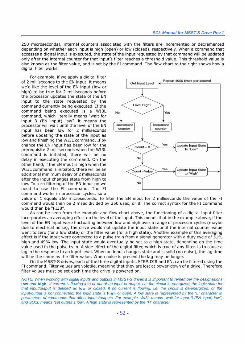
SCL Manual for MSST-S Drive Rev.1
- 52 -
250 microseconds), internal counters associated with the filters are incremented or decrementeddepending on whether each input is high (open) or low (closed), respectively. When a command thataccesses a digital input is executed, the state of the input requested by that command will be updatedonly after the internal counter for that input’s filter reaches a threshold value. This threshold value isalso known as the filter value, and is set by the FI command. The flow chart to the right shows how adigital filter works.
For example, if we apply a digital filterof 2 milliseconds to the EN input, it meanswe’d like the level of the EN input (low orhigh) to be true for 2 milliseconds beforethe processor updates the state of the ENinput to the state requested by thecommand currently being executed. If thecommand being executed is a WI3Lcommand, which literally means “wait forinput 3 (EN input) low”, it means theprocessor will wait until the level of the ENinput has been low for 2 millisecondsbefore updating the state of the input aslow and finishing the WI3L command. If bychance the EN input has been low for theprerequisite 2 milliseconds when the WI3Lcommand is initiated, there will be nodelay in executing the command. On theother hand, if the EN input is high when theWI3L command is initiated, there will be anadditional minimum delay of 2 millisecondsafter the input changes state from high tolow. To turn filtering of the EN input on weneed to use the FI command. The FIcommand works in processor cycles, so avalue of 1 equals 250 microseconds. To filter the EN input for 2 milliseconds the value of the FIcommand would then be 2 msec divided by 250 usec, or 8. The correct syntax for the FI commandwould then be “FI38”.
As can be seen from the example and flow chart above, the functioning of a digital input filterincorporates an averaging effect on the level of the input. This means that in the example above, if thelevel of the EN input were fluctuating between low and high over a range of processor cycles (maybedue to electrical noise), the drive would not update the input state until the internal counter valuewent to zero (for a low state) or the filter value (for a high state). Another example of this averagingeffect is if the input were connected to a pulse train from a signal generator with a duty cycle of 51%high and 49% low. The input state would eventually be set to a high state, depending on the timevalue used in the pulse train. A side effect of the digital filter, which is true of any filter, is to cause alag in the response to an input level. When an input changes state and is solid (no noise), the lag timewill be the same as the filter value. When noise is present the lag may be longer.
On the MSST-S drives, each of the three digital inputs, STEP, DIR and EN, can be filtered using theFI command. Filter values are volatile, meaning that they are lost at power-down of a drive. Thereforefilter values must be set each time the drive is powered on.
NOTE: When working with digital inputs and outputs in MSST-S drives it is important to remember the designationslow and high. If current is flowing into or out of an input or output, i.e. the circuit is energized; the logic state forthat input/output is defined as low or closed. If no current is flowing, i.e. the circuit is de-energized, or theinput/output is not connected, the logic state is high or open. A low state is represented by the “L”character inparameters of commands that affect inputs/outputs. For example, WI3L means “wait for input 3 (EN input) low”,and SO1L means “set output 1 low”. A high state is represented by the “H”character.
SCL Manual for MSST-S Drive Rev.1
- 53 -
FL - Feed to Length
Executes a Feed to Length (relative move) command. Move distance and direction come from thelast DI command. Speed, accel and decel are from VE, AC and DE commands respectively. Optionalparameter al-lows using a local distance for the FL command rather than the last DI value.
NOTE: The last DI command can be ignored/unaltered if a parameter is used with the FL command.
See also: AC, DE, DI, VE commands
Command Structure:FL{Parameter #1 }
Details:
Command Type BUFFEREDUsage WRITE ONLY
Non-Volatile NO
Register Access None
Parameter #1 * Relative distance
- units steps- range -2,147,483,647 to 2,147,483,647
sign determines direction: “-”for CCW, no sign for CW
Examples:
Command Drive sends NotesAC100 - Set accel rate to 100 rev/sec/secDE150 - Set decel rate to 150 rev/sec/secVE8 - Set velocity to 8 rev/secDI20000 - Set distance to 20000 steps in the CW directionFL - Initiate Feed to Length move
FL10000 - Initiate Feed to Length move of 10000 steps in theCW direction without affecting the last DI command
FL-400 - Initiate Feed to Length move of 400 steps in the CWdirection without affecting the last DI command
SCL Manual for MSST-S Drive Rev.1
- 54 -
FM - Feed to Sensor with Mask Distance
Executes a Feed to Sensor command, but sensor is ignored for the first DC counts of the move.Useful for masking a switch or clearing a part before sensing the correct stop input. DI sets thedistance to move after the stop input is triggered. AC sets accel rate, VE sets velocity, and DE setsdecel rate.
See also: DC and FS commands; see AT command for using AIN as sensor input
Command Structure:FM(Parameter #1)
Details:
Command Type BUFFEREDUsage WRITE ONLY
Non-Volatile NO
Register Access None
Parameter #1 Input, Input condition
- units integer, letter- range integer: 1 = STEP, 2 = DIR, 3 = EN, 4 = AIN
letter: L = low, H = high, F = falling edge, R = rising edge
Examples:Example: Parts are feeding on a conveyor which is being driven by the step motor. A sensordetects the leading edge of the part and stops. If the part has a hole in it, which is common,when you attempt to feed the next part into position you may in fact stop after feeding theprevious part only a short distance because the sensor will register the hole in the part ratherthan the leading edge of the next part. The solution is to use the FM command instead of the FScommand, and to set the DC command for the size of the part (or greater).
Example continued: The parts on the conveyor are 6 inches long. Your mechanical linkageprovides 2000 steps per inch. You want the leading edge of the part to stop moving 1 inch pastthe sensor, and therefore 5 inches of the part will not have gone past the sensor yet. To avoid holesin the part and see the next part properly, we need to mask 5 inches or more of the move. Hereare the commands you could use.
Command Drive sends NotesDI2000 - Set distance to stop past sensor at 1 inch (2000 steps)DC10200 - Set distance over which to ignore (mask) the sensor at 5.1 inches,
enough to allow the previous part to completely clear the sensorFM1F - Initiate FM move. Sensor is connected to input 1 and will close
when it sees a part
NOTE: When working with inputs and outputs in MSST-S drives it is important to remember the designations low andhigh. If current is flowing into or out of an input or output, i.e. the circuit is energized; the logic state for thatinput/output is defined as low or closed. If no current is flowing, i.e. the circuit is de-energized, or the input/outputis not connected, the logic state is high or open. A low state is represented by the “L”character in parameters ofcommands that affect inputs/outputs. For example, WI3L means “wait for input 3 (EN input) low”, and SO1L means“set output 1 low”. A high state is represented by the “H”character.
NOTE: When working with the analog input of an MSST-S drive (AIN terminal), “L”designates an analog value lowerthan the value set by the AT command. Similarly “H”designates an analog value greater than the value set by theAT command.
SCL Manual for MSST-S Drive Rev.1
- 55 -
FO - Feed to Length and Set Output
Same as Feed to Length (FL) but changes the state of an output during the move. Overall movedistance is defined by the DI command. Accel rate, decel rate, and velocity are set by the AC, DE andVE commands, respectively. Distance within overall move at which output condition should be set isdefined by the DC command.
NOTE: Dedicated output functions - alarm output, brake output, motion output - must be configured as generalpurpose before the FO command can be used with the drive’s output. See AO, BO, and MO commands.
See Also: DC, AO, BO, MO commands
Command Structure:FO(Parameter #1)
Details:
Command Type BUFFEREDUsage WRITE ONLY
Non-Volatile NO
Register Access None
Parameter #1 Output, Output condition
- units integer, letter- range integer: 1
letter: L = low (closed), H = high (open)
Examples:Example: You’re feeding parts to be cut to length. For maximum throughput, you want to triggerthe cut-off knife as the part is nearing the final position.
Command Drive sends NotesAC100 - Set accel rate to 100 rev/sec/sec
DE100 - Set decel rate to 100 rev/sec/sec
VE2.5 - Set velocity to 2.5 rev/sec
DI20000 - Overall move distance set to 20000 steps
DC15000 - Set output distance set to 15000 stepsFO1L - Initiate move and set output low at 15000 steps
NOTE: When working with digital inputs and outputs in MSST-S drives it is important to remember the designationslow and high. If current is flowing into or out of an input or output, i.e. the circuit is energized, the logic state for thatinput/output is defined as low or closed. If no current is flowing, i.e. the circuit is de-energized, or the input/output isnot connected, the logic state is high or open. A low state is represented by the “L”character in parameters ofcommands that affect inputs/outputs. For example, WI3L means “wait for input 3 (EN input) low”, and SO1L means“set output 1 low”. A high state is represented by the “H”character.

SCL Manual for MSST-S Drive Rev.1
- 56 -
FP - Feed to Position
Executes a Feed to Position (absolute) move. Move position comes from the last DI command. Speed,accel and decel are from VE, AC and DE commands, respectively. Optional parameter allows using alocal absolute position for the FP command rather than the last DI value.
NOTE: The last DI command can be ignored/unaltered if a parameter is used with the FP command.
See also: AC, DE, DI, VE commands
Command Structure:FP{Parameter #1 }
Details:
Command Type BUFFEREDUsage WRITE ONLY
Non-Volatile NO
Register Access None
Parameter #1* Absolute position
- units steps
- range -2,147,483,647 to 2,147,483,647
Examples:Example: After homing the motor you want to zero the home position and move to an absoluteposition 80000 steps from the new home position.
Command Drive sends NotesSP0 - Set current motor position as absolute zeroVE5 - Set velocity to 5 rev/secD180000 - Set move position to 80000 stepsFP - Initiate Feed to Position move
FP40000 - Initiate Feed to Position move to 40000 steps without affecting thethe last DI command
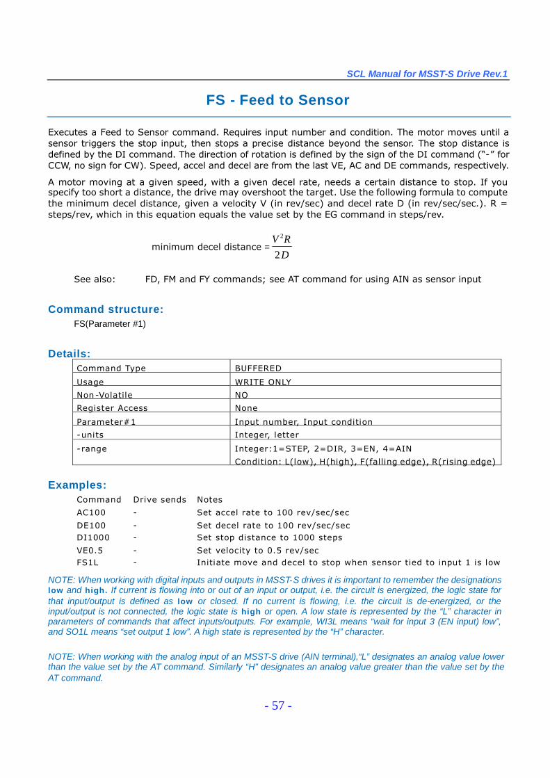
SCL Manual for MSST-S Drive Rev.1
- 57 -
FS - Feed to Sensor
Executes a Feed to Sensor command. Requires input number and condition. The motor moves until asensor triggers the stop input, then stops a precise distance beyond the sensor. The stop distance isdefined by the DI command. The direction of rotation is defined by the sign of the DI command (“-”forCCW, no sign for CW). Speed, accel and decel are from the last VE, AC and DE commands, respectively.
A motor moving at a given speed, with a given decel rate, needs a certain distance to stop. If youspecify too short a distance, the drive may overshoot the target. Use the following formula to computethe minimum decel distance, given a velocity V (in rev/sec) and decel rate D (in rev/sec/sec.). R =steps/rev, which in this equation equals the value set by the EG command in steps/rev.
minimum decel distance =DRV
2
2
See also: FD, FM and FY commands; see AT command for using AIN as sensor input
Command structure:FS(Parameter #1)
Details:Command Type BUFFERED
Usage WRITE ONLY
Non-Volatile NO
Register Access None
Parameter#1 Input number, Input condition
-units Integer, letter
-range Integer:1=STEP, 2=DIR, 3=EN, 4=AIN
Condition: L(low), H(high), F(falling edge), R(rising edge)
Examples:Command Drive sends Notes
AC100 - Set accel rate to 100 rev/sec/sec
DE100 - Set decel rate to 100 rev/sec/secDI1000 - Set stop distance to 1000 steps
VE0.5 - Set velocity to 0.5 rev/secFS1L - Initiate move and decel to stop when sensor tied to input 1 is low
NOTE: When working with digital inputs and outputs in MSST-S drives it is important to remember the designationslow and high. If current is flowing into or out of an input or output, i.e. the circuit is energized, the logic state forthat input/output is defined as low or closed. If no current is flowing, i.e. the circuit is de-energized, or theinput/output is not connected, the logic state is high or open. A low state is represented by the “L”character inparameters of commands that affect inputs/outputs. For example, WI3L means “wait for input 3 (EN input) low”,and SO1L means “set output 1 low”. A high state is represented by the “H”character.
NOTE: When working with the analog input of an MSST-S drive (AIN terminal),“L”designates an analog value lowerthan the value set by the AT command. Similarly “H”designates an analog value greater than the value set by theAT command.
SCL Manual for MSST-S Drive Rev.1
- 58 -
FY - Feed to Sensor with Safety Distance
Executes a Feed to Sensor move, but monitors a predefined safety distance. If sensor is not found beforedistance reaches the safety distance DC, the motor is stopped and the drive sends the host anexclamation point (“!”). DI defines the direction of rotation and the stop distance to move after the sensortriggers the stop input. Accel rate, decel rate, and velocity are set by the AC, DE, and VE commands,respectively. Note that the final motor position if the sensor is not found will be the safety distance plusthe distance required to decelerate the load, which is dependent on the decel rate DE.
This command is useful for avoiding machine jams or detecting the end of a roll of labels. For example,you are feeding labels and you want to stop each label 2000 steps after the sensor detects the leadingedge. The labels are 60,000 steps apart. Therefore, if you move the roll more than 60,000 steps withoutdetecting a new label, you must be at the end of the roll.
See also: DC, DE, FD, FM and FS commands; see AT command for using AIN as sensor input
Command Structure:FY(Parameter #1)
Details:
Command Type BUFFEREDUsage WRITE ONLY
Non-Volatile NO
Register Access None
Parameter #1 Input number, Input condition
- units integer, letter- range integer: 1 = STEP, 2 = DIR, 3 = EN
condition: L (low), H (high), F (falling edge), R (rising edge)
Examples:Command Drive sends NotesAC50 - Set accel rate to 50 rev/sec/sec
DE50 - Set decel rate to 100 rev/sec/sec
VE2.5 - Set velocity to 2.5 rev/secDI2000 - Set distance to stop beyond sensor to 2000 steps, and set move
direction to CW
DC60000 - Set safety distance to 60000 stepsFY2L - Launch Feed to Sensor: motor will stop when input 2 is low or when
60000 steps are reached: whichever event comes first
NOTE: When working with digital inputs and outputs in MSST-S drives it is important to remember the designationslow and high. If current is flowing into or out of an input or output, i.e. the circuit is energized, the logic state forthat input/output is defined as low or closed. If no current is flowing, i.e. the circuit is de-energized, or theinput/output is not connected, the logic state is high or open. A low state is represented by the “L”character inparameters of commands that affect inputs/outputs. For example, WI3L means “wait for input 3 (EN input) low”,and SO1L means “set output 1 low”. A high state is represented by the “H”character.
NOTE: When working with the analog input of an MSST-S drive (AIN terminal),“L”designates an analog value lowerthan the value set by the AT command. Similarly “H”designates an analog value greater than the value set by theAT command.

SCL Manual for MSST-S Drive Rev.1
- 59 -
HG - 4th Harmonic Filter Gain
Sets or requests the 4th harmonic filter gain setting. This setting works in conjunction with the 4thharmonic filter phase setting (HP) to reduce low-speed torque ripple in step motors.
NOTE: We strongly suggest you set this value in the ST Configurator software application only.
Affects: Low-speed performance of step motorsSee also: HP command
Command Structure:HG{Parameter #1 }
Details:
Command Type IMMEDIATEUsage READ/WRITE
Non-Volatile YES only when set in Configurator software, otherwise NO
Register Access None
Parameter #1 Filter gain
- units integer number
- range 0 - 32767
Example:
Command Drive sends NotesHG8000 - Set filter gain value to 8000
HG HG=8000
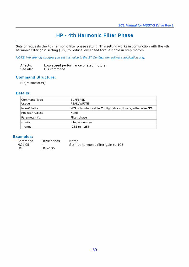
SCL Manual for MSST-S Drive Rev.1
- 60 -
HP - 4th Harmonic Filter Phase
Sets or requests the 4th harmonic filter phase setting. This setting works in conjunction with the 4thharmonic filter gain setting (HG) to reduce low-speed torque ripple in step motors.
NOTE: We strongly suggest you set this value in the ST Configurator software application only.
Affects: Low-speed performance of step motorsSee also: HG command
Command Structure:HP{Parameter #1}
Details:
Command Type BUFFEREDUsage READ/WRITE
Non-Volatile YES only when set in Configurator software, otherwise NO
Register Access None
Parameter #1 Filter phase
- units integer number
- range -255 to +255
Examples:Command Drive sends NotesHG1 05 - Set 4th harmonic filter gain to 105HG HG=105
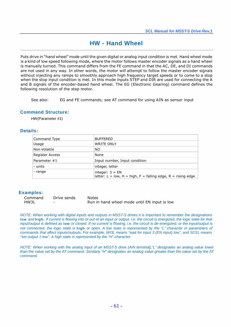
SCL Manual for MSST-S Drive Rev.1
- 61 -
HW - Hand Wheel
Puts drive in “hand wheel”mode until the given digital or analog input condition is met. Hand wheel modeis a kind of low speed following mode, where the motor follows master encoder signals as a hand wheelis manually turned. This command differs from the FE command in that the AC, DE, and DI commandsare not used in any way. In other words, the motor will attempt to follow the master encoder signalswithout injecting any ramps to smoothly approach high frequency target speeds or to come to a stopwhen the stop input condition is met. In this mode inputs STEP and DIR are used for connecting the Aand B signals of the encoder-based hand wheel. The EG (Electronic Gearing) command defines thefollowing resolution of the step motor.
See also: EG and FE commands; see AT command for using AIN as sensor input
Command Structure:HW(Parameter #1)
Details:
Command Type BUFFEREDUsage WRITE ONLY
Non-Volatile NO
Register Access None
Parameter #1 Input number, Input condition
- units integer, letter- range integer: 3 = EN
letter: L = low, H = high, F = falling edge, R = rising edge
NOTE: When working with digital inputs and outputs in MSST-S drives it is important to remember the designationslow and high. If current is flowing into or out of an input or output, i.e. the circuit is energized, the logic state for thatinput/output is defined as low or closed. If no current is flowing, i.e. the circuit is de-energized, or the input/output isnot connected, the logic state is high or open. A low state is represented by the “L”character in parameters ofcommands that affect inputs/outputs. For example, WI3L means “wait for input 3 (EN input) low”, and SO1L means“set output 1 low”. A high state is represented by the “H”character.
NOTE: When working with the analog input of an MSST-S drive (AIN terminal),“L”designates an analog value lowerthan the value set by the AT command. Similarly “H”designates an analog value greater than the value set by the ATcommand.
Examples:Command Drive sends NotesHW3L - Run in hand wheel mode until EN input is low
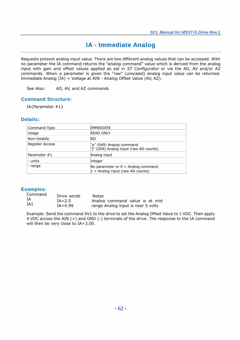
SCL Manual for MSST-S Drive Rev.1
- 62 -
IA - Immediate Analog
Requests present analog input value. There are two different analog values that can be accessed. Withno parameter the IA command returns the “analog command”value which is derived from the analoginput with gain and offset values applied as set in ST Configurator or via the AD, AV and/or AZcommands. When a parameter is given the “raw”(unscaled) analog input value can be returned.Immediate Analog (IA) = Voltage at AIN - Analog Offset Value (AV, AZ).
See Also: AD, AV, and AZ commands
Command Structure:
IA{Parameter #1}
Details:
Command Type IMMEDIATEUsage READ ONLY
Non-Volatile NORegister Access “a”(049) Analog command
“j”(058) Analog input (raw AD counts)
Parameter #1 Analog input
- units integer- range No parameter or 0 = Analog command
1 = Analog input (raw AD counts)
Examples:CommandIAIA1
Drive sendsIA=2.5IA=4.99
NotesAnalog command value is at midrange Analog input is near 5 volts
Example: Send the command AV1 to the drive to set the Analog Offset Value to 1 VDC. Then apply4 VDC across the AIN (+) and GND (-) terminals of the drive. The response to the IA commandwill then be very close to IA=3.00.
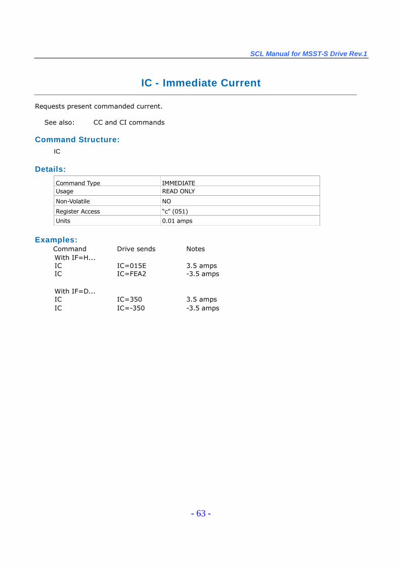
SCL Manual for MSST-S Drive Rev.1
- 63 -
IC - Immediate Current
Requests present commanded current.
See also: CC and CI commands
Command Structure:IC
Details:
Command Type IMMEDIATEUsage READ ONLY
Non-Volatile NO
Register Access “c”(051)
Units 0.01 amps
Examples:Command Drive sends NotesWith IF=H...IC IC=015E 3.5 ampsIC IC=FEA2 -3.5 amps
With IF=D...IC IC=350 3.5 ampsIC IC=-350 -3.5 amps
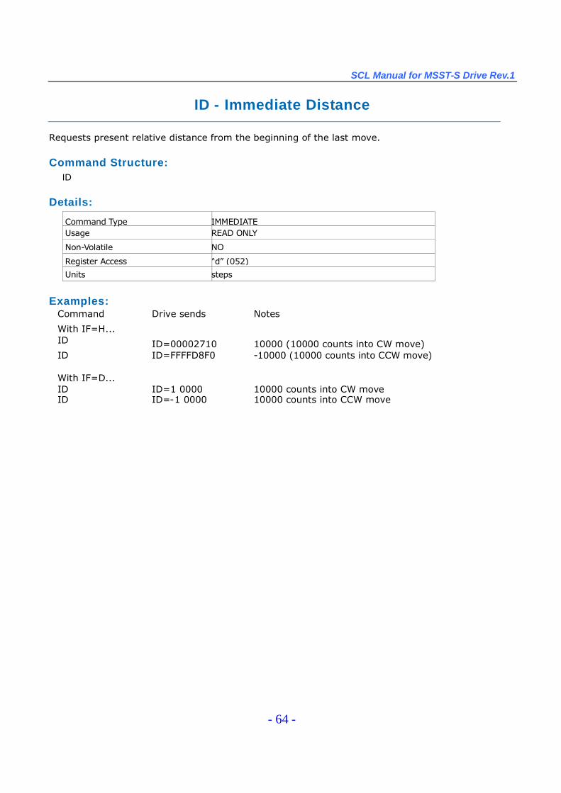
SCL Manual for MSST-S Drive Rev.1
- 64 -
ID - Immediate Distance
Requests present relative distance from the beginning of the last move.
Command Structure:ID
Details:
Command Type IMMEDIATEUsage READ ONLY
Non-Volatile NO
Register Access “d”(052)
Units steps
Examples:Command Drive sends Notes
With IF=H...ID ID=00002710 10000 (10000 counts into CW move)ID ID=FFFFD8F0 -10000 (10000 counts into CCW move)
With IF=D...ID ID=1 0000 10000 counts into CW moveID ID=-1 0000 10000 counts into CCW move
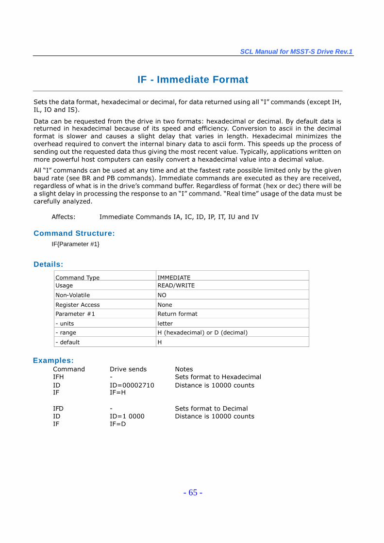
SCL Manual for MSST-S Drive Rev.1
- 65 -
IF - Immediate Format
Sets the data format, hexadecimal or decimal, for data returned using all “I”commands (except IH,IL, IO and IS).
Data can be requested from the drive in two formats: hexadecimal or decimal. By default data isreturned in hexadecimal because of its speed and efficiency. Conversion to ascii in the decimalformat is slower and causes a slight delay that varies in length. Hexadecimal minimizes theoverhead required to convert the internal binary data to ascii form. This speeds up the process ofsending out the requested data thus giving the most recent value. Typically, applications written onmore powerful host computers can easily convert a hexadecimal value into a decimal value.
All “I”commands can be used at any time and at the fastest rate possible limited only by the givenbaud rate (see BR and PB commands). Immediate commands are executed as they are received,regardless of what is in the drive’s command buffer. Regardless of format (hex or dec) there will bea slight delay in processing the response to an “I”command. “Real time”usage of the data must becarefully analyzed.
Affects: Immediate Commands IA, IC, ID, IP, IT, IU and IV
Command Structure:IF{Parameter #1}
Details:
Command Type IMMEDIATEUsage READ/WRITE
Non-Volatile NO
Register Access None
Parameter #1 Return format
- units letter
- range H (hexadecimal) or D (decimal)
- default H
Examples:Command Drive sends NotesIFH - Sets format to HexadecimalID ID=00002710 Distance is 10000 countsIF IF=H
IFD - Sets format to DecimalID ID=1 0000 Distance is 10000 countsIF IF=D
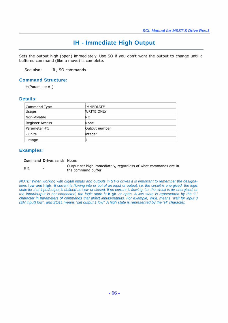
SCL Manual for MSST-S Drive Rev.1
- 66 -
IH - Immediate High Output
Sets the output high (open) immediately. Use SO if you don’t want the output to change until abuffered command (like a move) is complete.
See also: IL, SO commands
Command Structure:IH(Parameter #1)
Details:
Command Type IMMEDIATEUsage WRITE ONLY
Non-Volatile NO
Register Access None
Parameter #1 Output number
- units integer
- range 1
Examples:
Command Drives sends Notes
IH1 -Output set high immediately, regardless of what commands are inthe command buffer
NOTE: When working with digital inputs and outputs in ST-S drives it is important to remember the designa-tions low and high. If current is flowing into or out of an input or output, i.e. the circuit is energized; the logicstate for that input/output is defined as low or closed. If no current is flowing, i.e. the circuit is de-energized, orthe input/output is not connected, the logic state is high or open. A low state is represented by the “L”character in parameters of commands that affect inputs/outputs. For example, WI3L means “wait for input 3(EN input) low”, and SO1L means “set output 1 low”. A high state is represented by the “H”character.

SCL Manual for MSST-S Drive Rev.1
- 67 -
IL - Immediate Low Output
Sets the output low (closed) immediately. Use SO if you don’t want the output to change until abuffered command (like a move) is complete.
See also: IH, SO commands
Command Structure:IL(Parameter #1)
Details:
Command Type IMMEDIATEUsage WRITE ONLY
Non-Volatile NO
Register Access None
Parameter #1 Output number
- units integer
- range 1
NOTE: When working with digital inputs and outputs in MSST-S drives it is important to remember the designationslow and high. If current is flowing into or out of an input or output, i.e. the circuit is energized, the logic state for thatinput/output is defined as low or closed. If no current is flowing, i.e. the circuit is de-energized, or the input/output isnot connected, the logic state is high or open. A low state is represented by the “L”character in parameters ofcommands that affect inputs/outputs. For example, WI3L means “wait for input 3 (EN input) low”, and SO1L means“set output 1 low”. A high state is represented by the “H”character.
Examples:Command Drive sends NotesI L1 - Output set low immediately

SCL Manual for MSST-S Drive Rev.1
- 68 -
IO- Output Status
With no parameter this command requests the immediate status of the designated outputs. Thestatus is displayed as an 8-bit binary number with input 1 in the far right position (bit 0). With aparameter this command sets the outputs high or low using the decimal equivalent of the samebinary pattern. Logic zero (“0”) turns an output on by closing it.
NOTE: Since the MSST-S drives only have one digital output this command will only return values of 0 or 1.
See also: IS command
Command Structure:IO{Parameter #1 }
Details:
Command Type IMMEDIATEUsage READ/WRITE
Non-Volatile NO
Register Access None
Parameter #1 Decimal equivalent of binary output pattern
- units integer
- range 0, 1
Examples:Command Drive sends NotesIO IO=00000000 Output is low (closed)IO IO=00000001 Output is high (open)
IO0 - Set output low (closed)IO1 - Set output high (open)
NOTE: When working with digital inputs and outputs in MSST-S drives it is important to remember the designa-tions low and high. If current is flowing into or out of an input or output, i.e. the circuit is energized, the logic statefor that input/output is defined as low or closed. If no current is flowing, i.e. the circuit is de-energized, or theinput/output is not connected, the logic state is high or open. A low state is represented by the “L”character inparameters of commands that affect inputs/outputs. For example, WI3L means “wait for input 3 (EN input) low”,and SO1L means “set output 1 low”. A high state is represented by the “H”character.
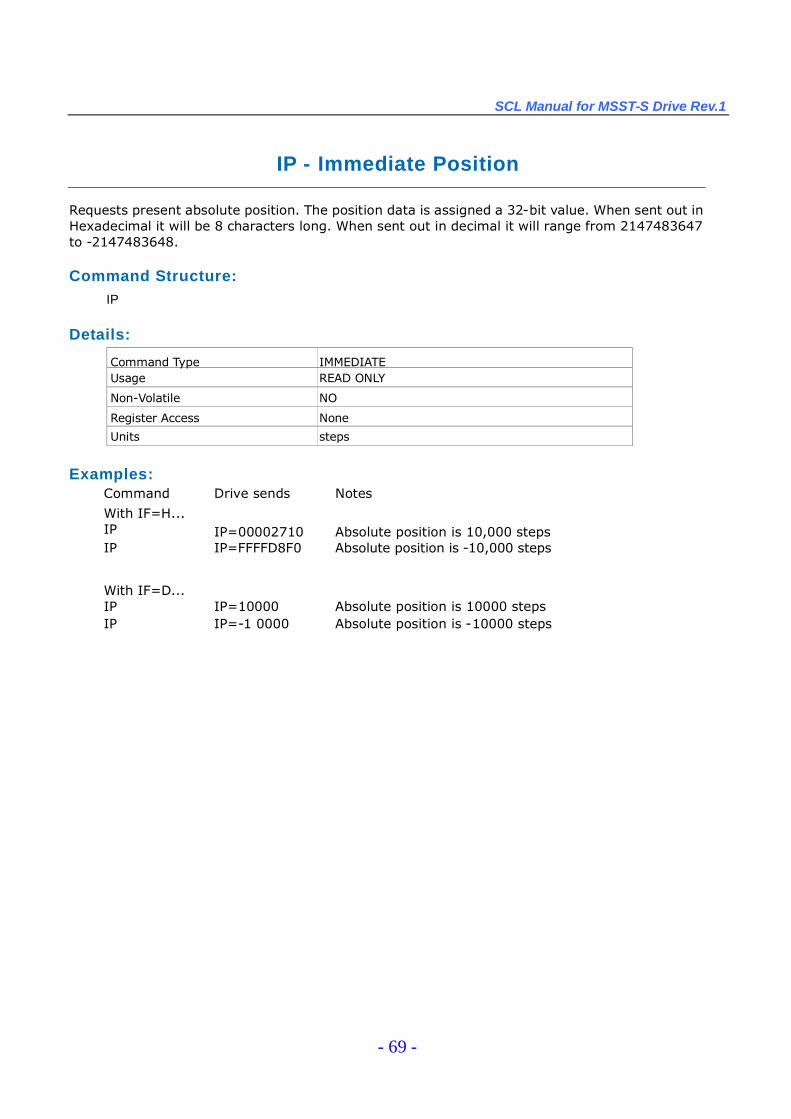
SCL Manual for MSST-S Drive Rev.1
- 69 -
IP - Immediate Position
Requests present absolute position. The position data is assigned a 32-bit value. When sent out inHexadecimal it will be 8 characters long. When sent out in decimal it will range from 2147483647to -2147483648.
Command Structure:IP
Details:
Command Type IMMEDIATEUsage READ ONLY
Non-Volatile NO
Register Access None
Units steps
Examples:Command Drive sends Notes
With IF=H...IP IP=00002710 Absolute position is 10,000 stepsIP IP=FFFFD8F0 Absolute position is -10,000 steps
With IF=D...IP IP=10000 Absolute position is 10000 stepsIP IP=-1 0000 Absolute position is -10000 steps
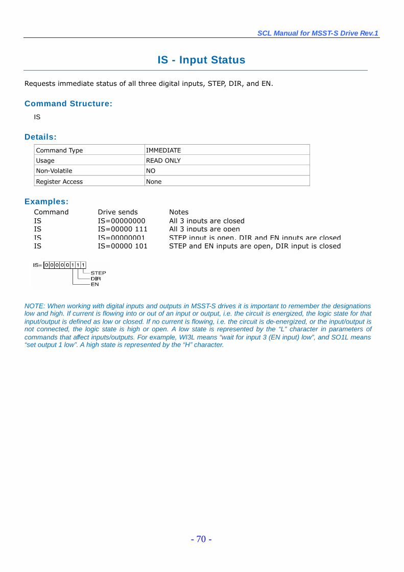
SCL Manual for MSST-S Drive Rev.1
- 70 -
IS - Input Status
Requests immediate status of all three digital inputs, STEP, DIR, and EN.
Command Structure:
IS
Details:
Command Type IMMEDIATE
Usage READ ONLY
Non-Volatile NO
Register Access None
Examples:Command Drive sends NotesIS IS=00000000 All 3 inputs are closedIS IS=00000 111 All 3 inputs are openIS IS=00000001 STEP input is open, DIR and EN inputs are closedIS IS=00000 101 STEP and EN inputs are open, DIR input is closed
NOTE: When working with digital inputs and outputs in MSST-S drives it is important to remember the designationslow and high. If current is flowing into or out of an input or output, i.e. the circuit is energized, the logic state for thatinput/output is defined as low or closed. If no current is flowing, i.e. the circuit is de-energized, or the input/output isnot connected, the logic state is high or open. A low state is represented by the “L”character in parameters ofcommands that affect inputs/outputs. For example, WI3L means “wait for input 3 (EN input) low”, and SO1L means“set output 1 low”. A high state is represented by the “H”character.
SCL Manual for MSST-S Drive Rev.1
- 71 -
IT - Immediate Temperature
Requests present value of the temperature sensor on the drive. The temperature reads out in 0.1degrees Centigrade resolution. The drive will fault when the temperature reaches a specifiedmaximum value. (See hardware manuals for details).
Command Structure:
IT
Details:Command Type IMMEDIATE
Usage READ ONLY
Non-Volatile NO
Register Access “t”(068)
Units 0.1 deg C
Examples:Command Drive sends Notes
IT IT=275 Drive temperature is 27.5 C。IT IT=310 Drive temperature is 31.0 Co
SCL Manual for MSST-S Drive Rev.1
- 72 -
IU - Immediate Voltage
Requests present value of the DC bus voltage. The voltage reads out in 0.1 volts resolution. The drivewill fault when the DC bus voltage reaches a specified maximum value. An Alarm will be set when theDC Bus voltage is less then a minimum value. (See user manuals for details).
Command Structure:
IU
Details:Command Type IMMEDIATE
Usage READ ONLY
Non-Volatile NO
Register Access “u”(069)
Units 0.1 Volts DC
Examples:Command Drive sends Notes
With IF=H…
IU IU=01E2 DC supply voltage is 48.2 Volts
With IF=D…
IU IU=482 DC supply voltage is 48.2 Volts
SCL Manual for MSST-S Drive Rev.1
- 73 -
IV - Immediate Velocity
Requests present velocity of the motor in rpm.
Command Structure:
IV(Parameter #1)
Details:
Command Type IMMEDIATE
Usage READ ONLY
Non-Volatile NO
Register Access “w”(071)Target velocity
Parameter # 1 Velocity selector
-units integer
-range 1 = target velocity
Examples:Command Drive sends Notes
IV1 IV=1000 Motor is running at 1000 rpm
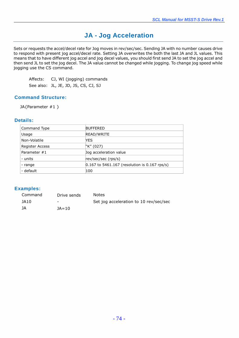
SCL Manual for MSST-S Drive Rev.1
- 74 -
JA - Jog Acceleration
Sets or requests the accel/decel rate for Jog moves in rev/sec/sec. Sending JA with no number causes driveto respond with present jog accel/decel rate. Setting JA overwrites the both the last JA and JL values. Thismeans that to have different jog accel and jog decel values, you should first send JA to set the jog accel andthen send JL to set the jog decel. The JA value cannot be changed while jogging. To change jog speed whilejogging use the CS command.
Affects: CJ, WI (jogging) commands
See also: JL, JE, JD, JS, CS, CJ, SJ
Command Structure:
JA{Parameter #1 }
Details:
Command Type BUFFERED
Usage READ/WRITE
Non-Volatile YES
Register Access “K”(027)
Parameter #1 Jog acceleration value
- units rev/sec/sec (rps/s)
- range 0.167 to 5461.167 (resolution is 0.167 rps/s)
- default 100
Examples:Command Drive sends Notes
JA10 - Set jog acceleration to 10 rev/sec/sec
JA JA=10
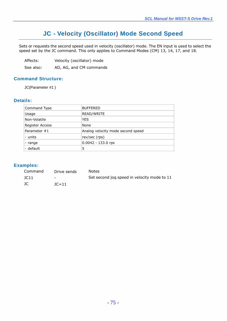
SCL Manual for MSST-S Drive Rev.1
- 75 -
JC - Velocity (Oscillator) Mode Second Speed
Sets or requests the second speed used in velocity (oscillator) mode. The EN input is used to select thespeed set by the JC command. This only applies to Command Modes (CM) 13, 14, 17, and 18.
Affects: Velocity (oscillator) mode
See also: AD, AG, and CM commands
Command Structure:
JC{Parameter #1 }
Details:
Command Type BUFFERED
Usage READ/WRITE
Non-Volatile YES
Register Access None
Parameter #1 Analog velocity mode second speed
- units rev/sec (rps)
- range 0.0042 - 133.0 rps
- default 5
Examples:Command Drive sends Notes
JC11 - Set second jog speed in velocity mode to 11
JC JC=11

SCL Manual for MSST-S Drive Rev.1
- 76 -
JD –Jog Disable
Disables the STEP and DIR inputs as jog inputs during a WI instruction.
Affects: Jogging during WI commandSee also: JE and WI commands
Command Structure:
JD
Details:
Command Type BUFFERED
Usage WRITE ONLY
Non-Volatile NO
Register Access None
Examples:
Command Drive sends Notes
JD - Disable jogging while executing a WI

SCL Manual for MSST-S Drive Rev.1
- 77 -
JE - Jog Enable
Enables the STEP and DIR inputs as jog inputs during a WI instruction. Jog accel, decel and velocity are setusing the JA, JL, and JS commands, respectively.
The STEP and DIR inputs can each be assigned to only one function in an application. If you want to usethe STEP and DIR inputs as jog inputs you can define them as such with the JE command. JE takes noeffect if the drive is set in Command Mode (CM) 7, 11, 12, 13, 14, 15, 16, 17 or 18, because these modespredefine these inputs and take precedence over the JE command. Also, setting the DL command (to 1 or2) after setting the JE command reassigns the STEP and DIR inputs as end-of-travel limit inputs and turnsoff jogging functionality. In other words, the JE and DL commands, as well as Command Modes (CM) 7,11, 12, 13, 14, 15, 16, 17 and 18 each assign a usage to the STEP and DIR inputs. Each of these mustexclusively use the STEP and DIR inputs. Command Modes are most dominant and will continuallyprevent JE and DL from using the inputs. JE and DL exclude each other by overwriting the usage of theSTEP and DIR inputs.
To enable jogging with the STEP and DIR inputs simply execute the JE command with CM=21 or CM=22.
Affects: Jogging during WI command
See also: JD and WI commands
Command Structure:
JE
Details:Command Type BUFFERED
Usage WRITE ONLY
Non-Volatile NO
Register Access None
Examples:Command Drive sends Notes
JE - Enable jogging while executing the WI
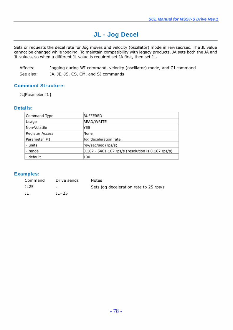
SCL Manual for MSST-S Drive Rev.1
- 78 -
JL - Jog Decel
Sets or requests the decel rate for Jog moves and velocity (oscillator) mode in rev/sec/sec. The JL valuecannot be changed while jogging. To maintain compatibility with legacy products, JA sets both the JA andJL values, so when a different JL value is required set JA first, then set JL.
Affects: Jogging during WI command, velocity (oscillator) mode, and CJ command
See also: JA, JE, JS, CS, CM, and SJ commands
Command Structure:
JL{Parameter #1 }
Details:
Command Type BUFFERED
Usage READ/WRITE
Non-Volatile YES
Register Access None
Parameter #1 Jog deceleration rate
- units rev/sec/sec (rps/s)
- range 0.167 - 5461.167 rps/s (resolution is 0.167 rps/s)
- default 100
Examples:Command Drive sends Notes
JL25 - Sets jog deceleration rate to 25 rps/s
JL JL=25
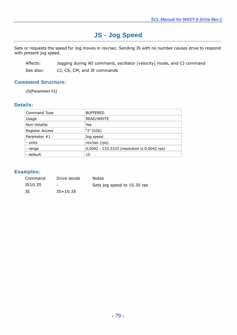
SCL Manual for MSST-S Drive Rev.1
- 79 -
JS - Jog Speed
Sets or requests the speed for Jog moves in rev/sec. Sending JS with no number causes drive to respondwith present jog speed.
Affects: Jogging during WI command, oscillator (velocity) mode, and CJ command
See also: CJ, CS, CM, and JE commands
Command Structure:
JS{Parameter #1}
Details:
Command Type BUFFERED
Usage READ/WRITE
Non-Volatile Yes
Register Access “J”(026)
Parameter #1 Jog speed
- units rev/sec (rps)
- range 0.0042 - 133.3333 (resolution is 0.0042 rps)
- default 10
Examples:Command Drive sends Notes
JS10.35 - Sets jog speed to 10.35 rps
JS JS=10.35
SCL Manual for MSST-S Drive Rev.1
- 80 -
MD - Motor Disable
Disables motor outputs (reduces motor current to zero). Disabling the motor also activates theoutput when set to function as a Brake Output (BO command).
Affects: All Motion commandsSee also: BD, BO, and ME commands
Command Structure:
MD
Details:Command Type BUFFERED
Usage WRITE ONLY
Non-Volatile No
Register Access None
Examples:Command Drive sends Notes
MD - Drive turns off current to the motor
SCL Manual for MSST-S Drive Rev.1
- 81 -
ME - Motor Enable
Restores drive current to motor. If the drive cannot be enabled due to the Enable Input (SI) state, thedrive will respond with a “&”which indicates that the drive could not be enabled. Enabling the motor alsodeactivates the output when set to function as a Brake Output (BO command). Also, enabling of the motoris delayed by the BE (Brake Engage) time delay when the output is set to function as a Brake Output.
IMPORTANT: This command restores the previous mode of operation. If for example the drive is operating invelocity (oscillator) mode the motor may immediately start moving after sending the ME command. Externalinputs to the drive must be sequenced properly to avoid unpredicted operation.
Affects: All motion commands
See also: BE, BO, and MD commands
Command Structure:
ME
Details:
Command Type BUFFERED
Usage WRITE ONLY
Non-Volatile NO
Register Access None
Examples:Command Drive sends Notes
ME - Motor current is restored
ME & Motor current is NOT restored: check Servo Enable input
Proper state
SCL Manual for MSST-S Drive Rev.1
- 82 -
MN - Model Number
Requests the drive’s Model Number. Drive returns a single character that is a code for the model number.
NOTE: Unlike most other commands that request data back from the drive, where the drive will send theoriginal Command Code with an “=”and then a value, the drive’s response to the MN command is a singlecharacter code (see below).
Command Structure:
MN
Details:
Command Type IMMEDIATE
Usage READ ONLY
Non-Volatile NO
Register Access None
Units character code
Range D = MSST5-S
E = MSST10-S
Examples:
Command Drive sends Notes
MN MN=E Connected drive is an MSST10-S

SCL Manual for MSST-S Drive Rev.1
- 83 -
MO - Motion Output
Defines the drive’s digital output as a Motion Output.
The output of an MSST-S drive can be assigned to one of four functions: alarm output, brake output,motion output, or tach output. Each of these functions must exclusively use the output, so only onefunction is allowed. There are two ways to define the function of this output: via ST Configurator or viaSCL commands. To set the output as a motion output, use the MO command and one of the codesbelow.
NOTE: Setting the MO command to 1 or 2 overrides previous assignments of this output’s function. Similarly, if youuse the AO or BO command to set the function of the output after setting the MO command to 1 or 2, usage of theoutput will be reassigned and MO will be automatically set to 3.
There are four Motion Output states that can be defined with the MO command:
MO1: Output is closed (energized) when motor is not moving.MO2: Output is open (de-energized) when motor is not moving.MO3: Output is not used as a Motion Output and can be used for another automatic output
function or as a general purpose output.MO4: Output is used as a Tach Output. Use ST Configurator to set the resolution of the Tach
Output function.
Affects: Function of digital output
See also: AO and BO commands
Command Structure:
MO{Parameter #1 }
Details:
Command Type BUFFERED
Usage READ/WRITE
Non-Volatile Yes
Register Access None
Parameter #1 Condition code
- units integer
- range 1, 2, 3, or 4 (see above)
- default 3
Examples:Command Drive sends Notes
MO1 - Output will be closed when motor is not moving
MO MO=1
NOTE: When working with digital inputs and outputs in MSST-S drives it is important to remember the designa - tions lowand high. If current is flowing into or out of an input or output, i.e. the circuit is energized, the logic state for thatinput/output is defined as low or closed. If no current is flowing, i.e. the circuit is de-energized, or the input/output is notconnected, the logic state is high or open. A low state is represented by the “L”character in parameters of commandsthat affect inputs/outputs. For example, WI3L means “wait for input 3 (EN input) low”, and SO1L means “set output 1low”. A high state is represented by the “H”character.
SCL Manual for MSST-S Drive Rev.1
- 84 -
PB - Power-up Baud Rate
Sets or requests the power-up baud rate for RS-232 serial communications. When executed, thiscommand sets the baud rate and immediately saves it to non-volatile memory.
At power-up the drive defaults to 9600 baud. If a host system is not detected after 1 second and thedrive is configured for host operation the drive will set the baud rate according to the value stored inthe power-up baud rate non-volatile parameter. A host system can change the baud rate at any time.
NOTE: Setting the baud rate takes effect immediately.
See also: BR, PR, and TD commands
Command Structure:
PB{Parameter #1}
Details:
Command Type BUFFERED
Usage READ/WRITE
Non-Volatile YES
Register Access None
Parameter #1 Baud rate code
- units integer code
- range 1 - 9600
2 - 19200
3 - 38400
4 - 57600
5 - 115200- default 1
Examples:Command Drive sends Notes
PB2 - Power–up baud rate is set to 19200 and this value issaved to non-volatile memory
PB PB=2

SCL Manual for MSST-S Drive Rev.1
- 85 -
PC - Power-up Current
Sets or requests the current setting of the drive. This command differs from the CC command in that thePC setting is saved to non-volatile memory as the command is executed.
Affects: Motor current, motor torque
See also: CC and PI commands
Command Structure:
PC{Parameter #1 }
Details:Command Type BUFFERED
Usage READ/WRITE
Non-Volatile YES
Register Access None
Parameter #1 Power-up current setting
- units Amps (resolution is 0.01 Amps)
- range 0 - 5.0 (MSST5-S*)
0 - 10.0 (MSST1 0-S*)
*Current settings in MSST drives depend on the selected motor. Use ST Configurator software toselect a motor and set the maximum and idle current settings
Examples:Command Drive sends Notes
PC3.2 - Set power-up current to 3.2 Amps
PC PC3.2
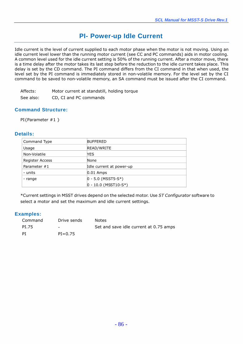
SCL Manual for MSST-S Drive Rev.1
- 86 -
PI- Power-up Idle Current
Idle current is the level of current supplied to each motor phase when the motor is not moving. Using anidle current level lower than the running motor current (see CC and PC commands) aids in motor cooling.A common level used for the idle current setting is 50% of the running current. After a motor move, thereis a time delay after the motor takes its last step before the reduction to the idle current takes place. Thisdelay is set by the CD command. The PI command differs from the CI command in that when used, thelevel set by the PI command is immediately stored in non-volatile memory. For the level set by the CIcommand to be saved to non-volatile memory, an SA command must be issued after the CI command.
Affects: Motor current at standstill, holding torque
See also: CD, CI and PC commands
Command Structure:
PI{Parameter #1 }
Details:Command Type BUFFERED
Usage READ/WRITE
Non-Volatile YES
Register Access None
Parameter #1 Idle current at power-up
- units 0.01 Amps
- range 0 - 5.0 (MSST5-S*)
0 - 10.0 (MSST10-S*)
*Current settings in MSST drives depend on the selected motor. Use ST Configurator software toselect a motor and set the maximum and idle current settings.
Examples:Command Drive sends Notes
PI.75 - Set and save idle current at 0.75 amps
PI PI=0.75

SCL Manual for MSST-S Drive Rev.1
- 87 -
PM - Power-up Mode
Sets or requests the power-up mode of the drive. PM determines how the drive is configured for serialcommunications at power-up. For SCL applications set PM=2 or PM=5.
Affects: Serial communications
See also: CM command
Command Structure:
PM {Parameter #1 }
Details:
Command Type BUFFERED
Usage READ/WRITENon-Volatile YES
Register Access NoneParameter #1 Power on mode- units integer code- range 2 - SCL / Host command (drive enabled)
3 - ST Configurator only4 - MisNet Hub
5 - SCL / Host command (drive disabled)
Examples:Command Drive sends Notes
PM2 - Drive will power up in SCL mode
PM PM=2
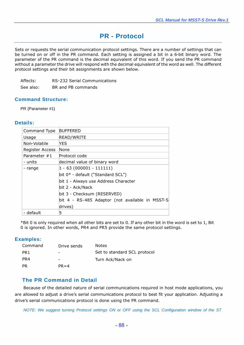
SCL Manual for MSST-S Drive Rev.1
- 88 -
PR - Protocol
Sets or requests the serial communication protocol settings. There are a number of settings that canbe turned on or off in the PR command. Each setting is assigned a bit in a 6-bit binary word. Theparameter of the PR command is the decimal equivalent of this word. If you send the PR commandwithout a parameter the drive will respond with the decimal equivalent of the word as well. The differentprotocol settings and their bit assignments are shown below.
Affects: RS-232 Serial Communications
See also: BR and PB commands
Command Structure:
PR {Parameter #1}
Details:
Command Type BUFFERED
Usage READ/WRITENon-Volatile YESRegister Access NoneParameter #1 Protocol code- units decimal value of binary word- range 1 - 63 (000001 - 111111)
bit 0* - default (“Standard SCL”)
bit 1 - Always use Address Characterbit 2 - Ack/Nack
bit 3 - Checksum (RESERVED)bit 4 - RS-485 Adaptor (not available in MSST-S
drives)- default 5
*Bit 0 is only required when all other bits are set to 0. If any other bit in the word is set to 1, Bit0 is ignored. In other words, PR4 and PR5 provide the same protocol settings.
Examples:Command Drive sends Notes
PR1 - Set to standard SCL protocol
PR4 - Turn Ack/Nack on
PR PR=4
The PR Command in DetailBecause of the detailed nature of serial communications required in host mode applications, you
are allowed to adjust a drive’s serial communications protocol to best fit your application. Adjusting adrive’s serial communications protocol is done using the PR command.
NOTE: We suggest turning Protocol settings ON or OFF using the SCL Configuration window of the ST
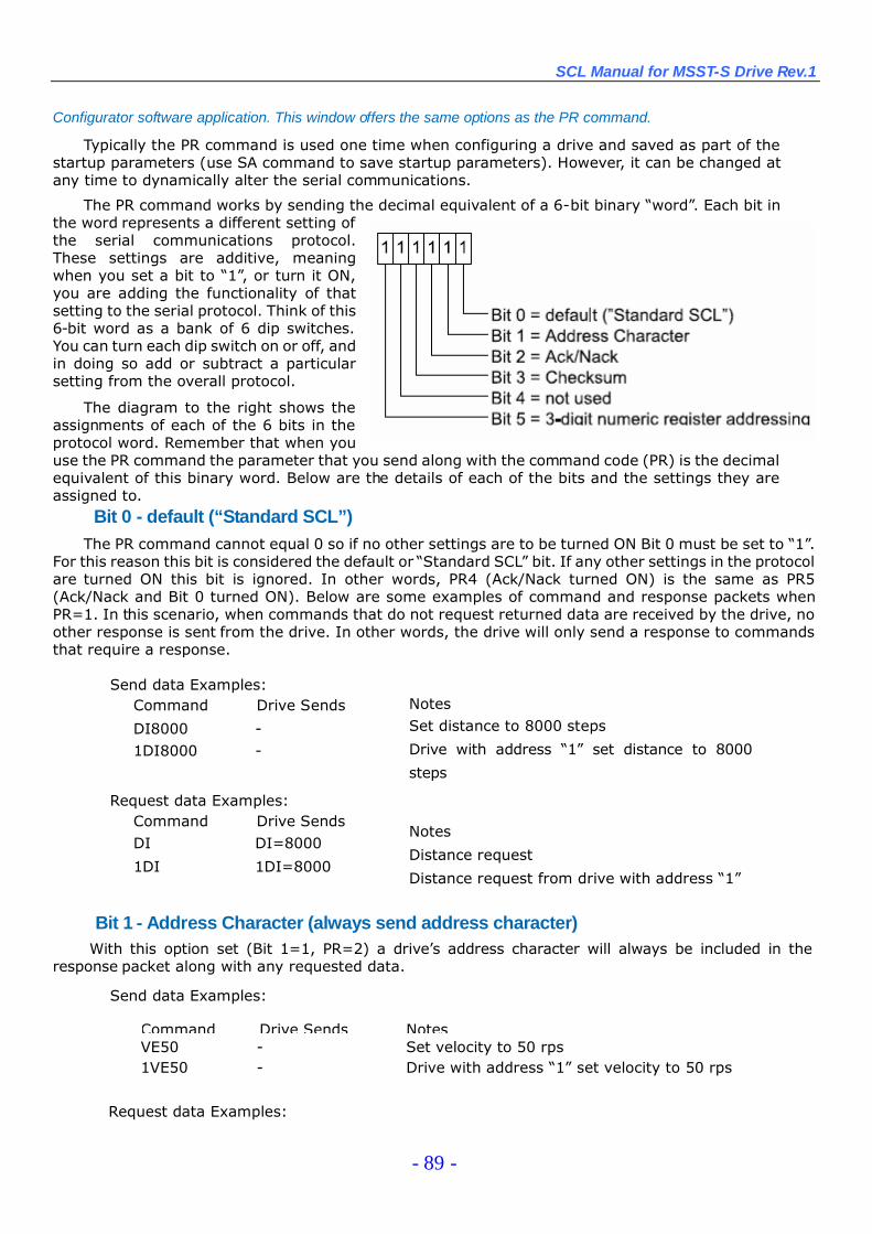
SCL Manual for MSST-S Drive Rev.1
- 89 -
Configurator software application. This window offers the same options as the PR command.
Typically the PR command is used one time when configuring a drive and saved as part of thestartup parameters (use SA command to save startup parameters). However, it can be changed atany time to dynamically alter the serial communications.
The PR command works by sending the decimal equivalent of a 6-bit binary “word”. Each bit inthe word represents a different setting ofthe serial communications protocol.These settings are additive, meaningwhen you set a bit to “1”, or turn it ON,you are adding the functionality of thatsetting to the serial protocol. Think of this6-bit word as a bank of 6 dip switches.You can turn each dip switch on or off, andin doing so add or subtract a particularsetting from the overall protocol.
The diagram to the right shows theassignments of each of the 6 bits in theprotocol word. Remember that when youuse the PR command the parameter that you send along with the command code (PR) is the decimalequivalent of this binary word. Below are the details of each of the bits and the settings they areassigned to.
Bit 0 - default (“Standard SCL”)The PR command cannot equal 0 so if no other settings are to be turned ON Bit 0 must be set to “1”.
For this reason this bit is considered the default or “Standard SCL”bit. If any other settings in the protocolare turned ON this bit is ignored. In other words, PR4 (Ack/Nack turned ON) is the same as PR5(Ack/Nack and Bit 0 turned ON). Below are some examples of command and response packets whenPR=1. In this scenario, when commands that do not request returned data are received by the drive, noother response is sent from the drive. In other words, the drive will only send a response to commandsthat require a response.
Send data Examples:Command Drive Sends
DI8000 -1DI8000 -
Request data Examples:Command Drive SendsDI DI=8000
1DI 1DI=8000
NotesSet distance to 8000 steps
Drive with address “1”set distance to 8000
steps
Notes
Distance request
Distance request from drive with address “1”
Bit 1 - Address Character (always send address character)With this option set (Bit 1=1, PR=2) a drive’s address character will always be included in the
response packet along with any requested data.
Send data Examples:
Command Drive Sends NotesVE50 - Set velocity to 50 rps1VE50 - Drive with address “1”set velocity to 50 rps
Request data Examples:
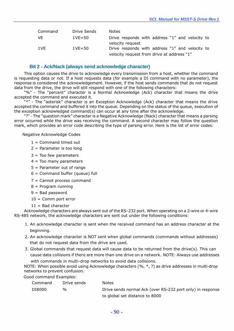
SCL Manual for MSST-S Drive Rev.1
- 90 -
Command Drive Sends Notes
VE 1VE=50 Drive responds with address “1”and velocity tovelocity request
1VE 1VE=50 Drive responds with address “1”and velocity tovelocity request from drive at address “1”
Bit 2 - Ack/Nack (always send acknowledge character)This option causes the drive to acknowledge every transmission from a host, whether the command
is requesting data or not. If a host requests data (for example a DI command with no parameter), theresponse is considered the acknowledgement. However, if the host sends commands that do not requestdata from the drive, the drive will still respond with one of the following characters:
“%”- The “percent”character is a Normal Acknowledge (Ack) character that means the driveaccepted the command and executed it.
“*”- The “asterisk”character is an Exception Acknowledge (Ack) character that means the driveaccepted the command and buffered it into the queue. Depending on the status of the queue, execution ofthe exception acknowledged command(s) can occur at any time after the acknowledge.
“?”-The “question mark”character is a Negative Acknowledge (Nack) character that means a parsingerror occurred while the drive was receiving the command. A second character may follow the questionmark, which provides an error code describing the type of parsing error. Here is the list of error codes:
Negative Acknowledge Codes
1 = Command timed out2 = Parameter is too long
3 = Too few parameters4 = Too many parameters
5 = Parameter out of range6 = Command buffer (queue) full
7 = Cannot process command8 = Program running
9 = Bad password
10 = Comm port error
11 = Bad characterAcknowledge characters are always sent out of the RS-232 port. When operating on a 2-wire or 4-wire
RS-485 network, the acknowledge characters are sent out under the following conditions:
1. An acknowledge character is sent when the received command has an address character at the
beginning.
2. An acknowledge character is NOT sent when global commands (commands without addresses)that do not request data from the drive are used.
3. Global commands that request data will cause data to be returned from the drive(s). This cancause data collisions if there are more than one drive on a network. NOTE: Always use addresses
with commands in multi-drop networks to avoid data collisions.NOTE: When possible avoid using Acknowledge characters (%, *, ?) as drive addresses in multi-dropnetworks to prevent confusion.Good command Examples:
Command Drive sends Notes
DI8000 % Drive sends normal Ack (over RS-232 port only) in response
to global set distance to 8000
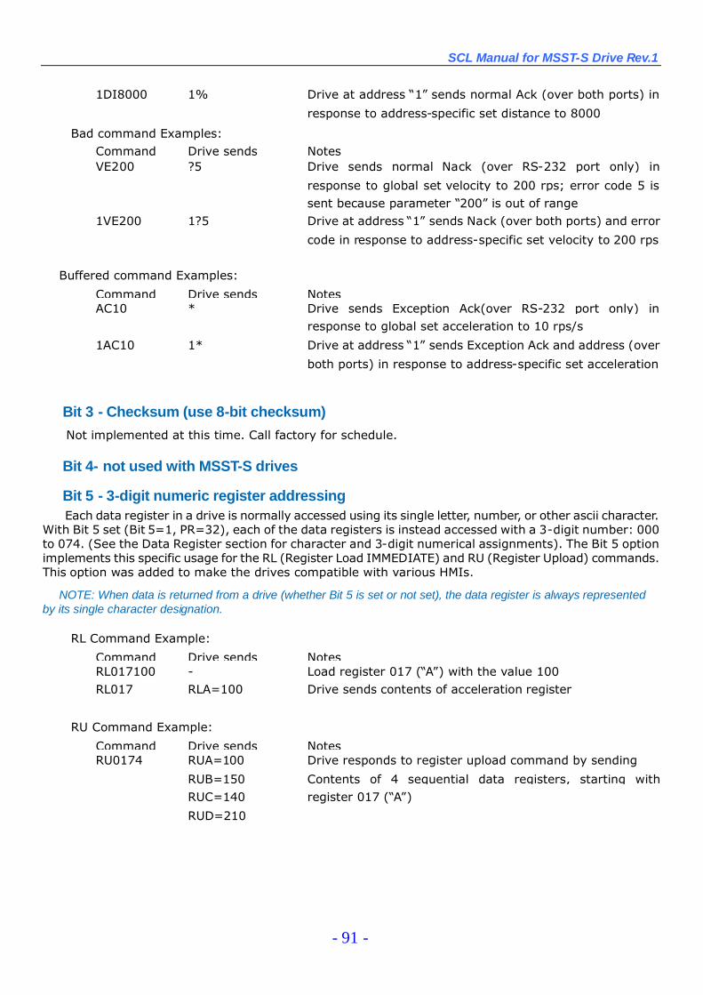
SCL Manual for MSST-S Drive Rev.1
- 91 -
1DI8000 1% Drive at address “1”sends normal Ack (over both ports) in
response to address-specific set distance to 8000
Bad command Examples:Command Drive sends NotesVE200 ?5 Drive sends normal Nack (over RS-232 port only) in
response to global set velocity to 200 rps; error code 5 issent because parameter “200”is out of range
1VE200 1?5 Drive at address “1”sends Nack (over both ports) and error
code in response to address-specific set velocity to 200 rps
Buffered command Examples:
Command Drive sends NotesAC10 * Drive sends Exception Ack(over RS-232 port only) in
response to global set acceleration to 10 rps/s
1AC10 1* Drive at address “1”sends Exception Ack and address (over
both ports) in response to address-specific set acceleration
Bit 3 - Checksum (use 8-bit checksum)
Not implemented at this time. Call factory for schedule.
Bit 4- not used with MSST-S drives
Bit 5 - 3-digit numeric register addressingEach data register in a drive is normally accessed using its single letter, number, or other ascii character.
With Bit 5 set (Bit 5=1, PR=32), each of the data registers is instead accessed with a 3-digit number: 000to 074. (See the Data Register section for character and 3-digit numerical assignments). The Bit 5 optionimplements this specific usage for the RL (Register Load IMMEDIATE) and RU (Register Upload) commands.This option was added to make the drives compatible with various HMIs.
NOTE: When data is returned from a drive (whether Bit 5 is set or not set), the data register is always representedby its single character designation.
RL Command Example:
Command Drive sends NotesRL017100 - Load register 017 (“A”) with the value 100RL017 RLA=100 Drive sends contents of acceleration register
RU Command Example:
Command Drive sends NotesRU0174 RUA=100
RUB=150RUC=140
Drive responds to register upload command by sending
Contents of 4 sequential data registers, starting withregister 017 (“A”)
RUD=210
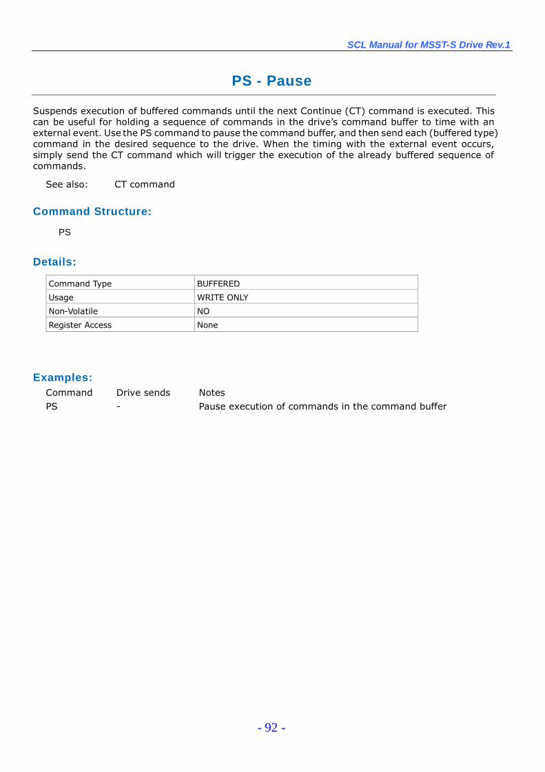
SCL Manual for MSST-S Drive Rev.1
- 92 -
PS - Pause
Suspends execution of buffered commands until the next Continue (CT) command is executed. Thiscan be useful for holding a sequence of commands in the drive’s command buffer to time with anexternal event. Use the PS command to pause the command buffer, and then send each (buffered type)command in the desired sequence to the drive. When the timing with the external event occurs,simply send the CT command which will trigger the execution of the already buffered sequence ofcommands.
See also: CT command
Command Structure:
PS
Details:
Command Type BUFFERED
Usage WRITE ONLY
Non-Volatile NO
Register Access None
Examples:Command Drive sends NotesPS - Pause execution of commands in the command buffer
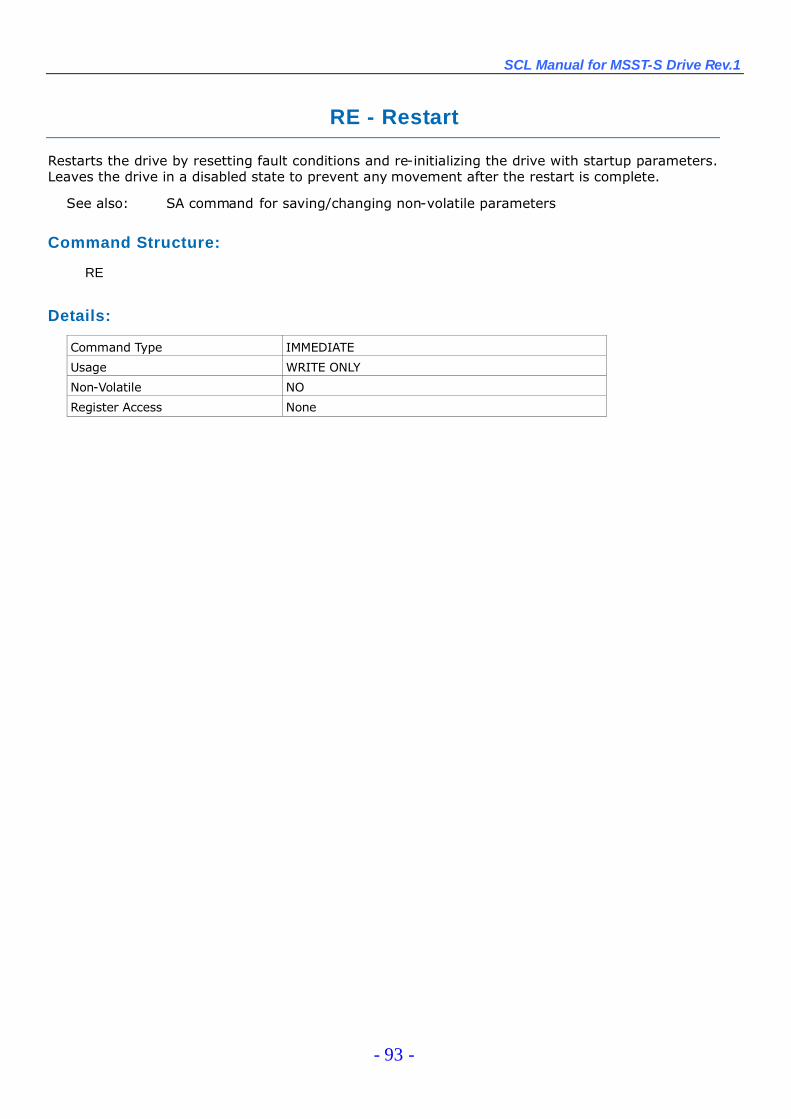
SCL Manual for MSST-S Drive Rev.1
- 93 -
RE - Restart
Restarts the drive by resetting fault conditions and re-initializing the drive with startup parameters.Leaves the drive in a disabled state to prevent any movement after the restart is complete.
See also: SA command for saving/changing non-volatile parameters
Command Structure:
RE
Details:
Command Type IMMEDIATE
Usage WRITE ONLY
Non-Volatile NO
Register Access None
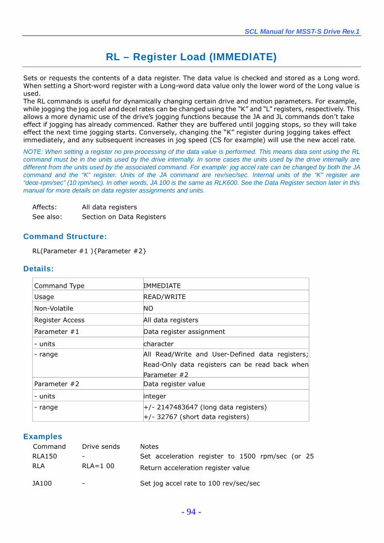
SCL Manual for MSST-S Drive Rev.1
- 94 -
RL – Register Load (IMMEDIATE)
Sets or requests the contents of a data register. The data value is checked and stored as a Long word.When setting a Short-word register with a Long-word data value only the lower word of the Long value isused.The RL commands is useful for dynamically changing certain drive and motion parameters. For example,while jogging the jog accel anddecel rates can be changed using the “K”and “L”registers, respectively. Thisallows a more dynamic use of the drive’s jogging functions because the JA and JL commands don’t takeeffect if jogging has already commenced. Rather they are buffered until jogging stops, so they will takeeffect the next time jogging starts. Conversely, changing the “K”register during jogging takes effectimmediately, and any subsequent increases in jog speed (CS for example) will use the new accel rate.
NOTE: When setting a register no pre-processing of the data value is performed. This means data sent using the RLcommand must be in the units used by the drive internally. In some cases the units used by the drive internally aredifferent from the units used by the associated command. For example: jog accel rate can be changed by both the JAcommand and the “K”register. Units of the JA command are rev/sec/sec. Internal units of the “K”register are“dece-rpm/sec”(10 rpm/sec). In other words, JA 100 is the same as RLK600. See the Data Register section later in thismanual for more details on data register assignments and units.
Affects: All data registersSee also: Section on Data Registers
Command Structure:
RL(Parameter #1 ){Parameter #2}
Details:
Command Type IMMEDIATE
Usage READ/WRITE
Non-Volatile NO
Register Access All data registers
Parameter #1 Data register assignment
- units character
- range All Read/Write and User-Defined data registers;
Read-Only data registers can be read back when
Parameter #2Parameter #2 Data register value
- units integer
- range +/- 2147483647 (long data registers)+/- 32767 (short data registers)
ExamplesCommand Drive sends NotesRLA150 - Set acceleration register to 1500 rpm/sec (or 25RLA RLA=1 00 Return acceleration register value
JA100 - Set jog accel rate to 100 rev/sec/sec
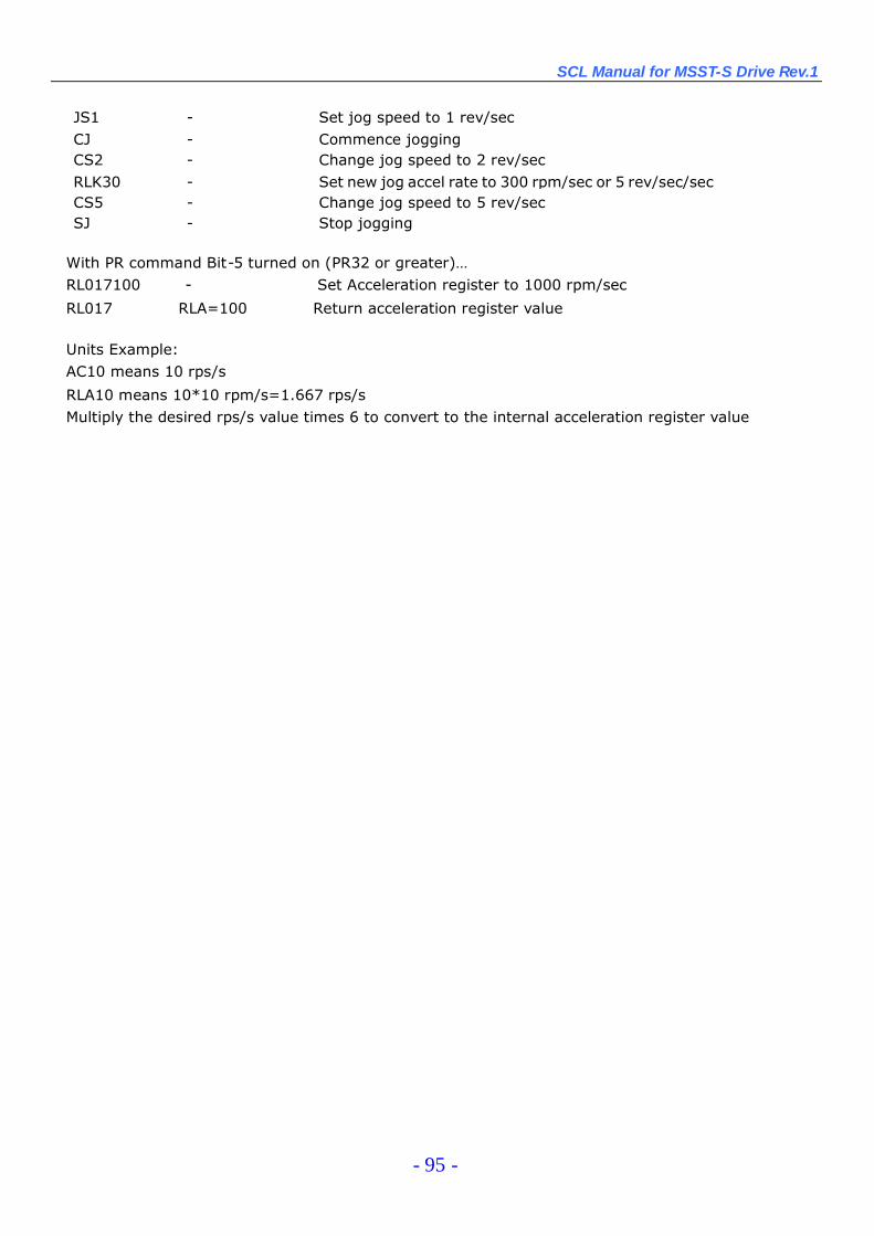
SCL Manual for MSST-S Drive Rev.1
- 95 -
JS1 - Set jog speed to 1 rev/secCJ - Commence joggingCS2 - Change jog speed to 2 rev/secRLK30 - Set new jog accel rate to 300 rpm/sec or 5 rev/sec/secCS5 - Change jog speed to 5 rev/secSJ - Stop jogging
With PR command Bit-5 turned on (PR32 or greater)…RL017100 - Set Acceleration register to 1000 rpm/sec
RL017 RLA=100 Return acceleration register value
Units Example:AC10 means 10 rps/s
RLA10 means 10*10 rpm/s=1.667 rps/sMultiply the desired rps/s value times 6 to convert to the internal acceleration register value
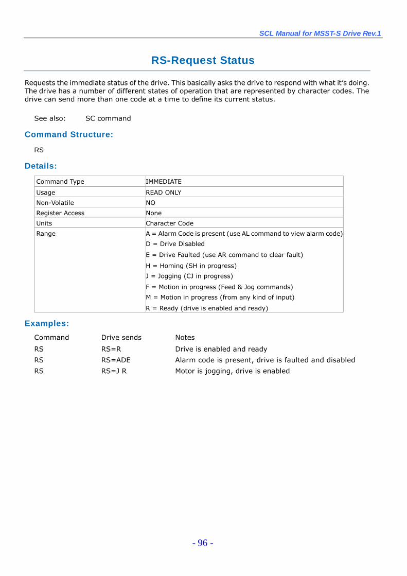
SCL Manual for MSST-S Drive Rev.1
- 96 -
RS-Request Status
Requests the immediate status of the drive. This basically asks the drive to respond with what it’s doing.The drive has a number of different states of operation that are represented by character codes. Thedrive can send more than one code at a time to define its current status.
See also: SC command
Command Structure:
RS
Details:
Command Type IMMEDIATE
Usage READ ONLY
Non-Volatile NO
Register Access None
Units Character Code
Range A = Alarm Code is present (use AL command to view alarm code)
D = Drive Disabled
E = Drive Faulted (use AR command to clear fault)
H = Homing (SH in progress)
J = Jogging (CJ in progress)
F = Motion in progress (Feed & Jog commands)
M = Motion in progress (from any kind of input)
R = Ready (drive is enabled and ready)
Examples:
Command Drive sends Notes
RS RS=R Drive is enabled and ready
RS RS=ADE Alarm code is present, drive is faulted and disabled
RS RS=J R Motor is jogging, drive is enabled
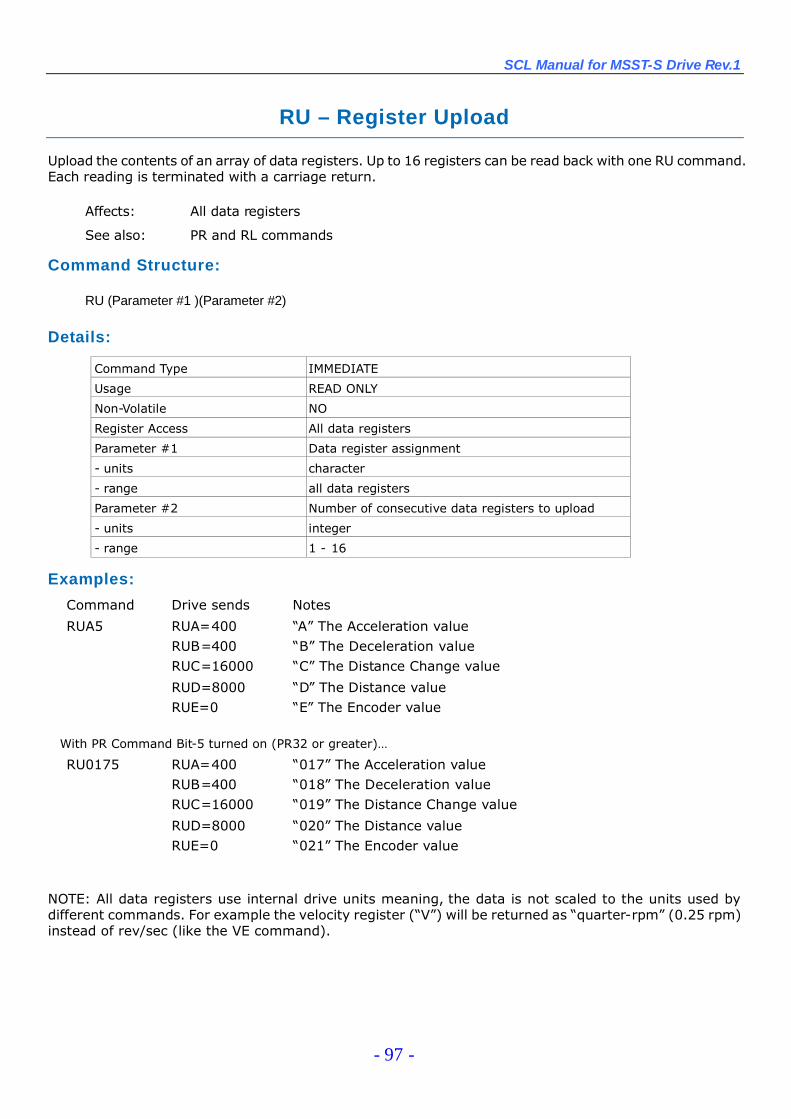
SCL Manual for MSST-S Drive Rev.1
- 97 -
RU –Register Upload
Upload the contents of an array of data registers. Up to 16 registers can be read back with one RU command.Each reading is terminated with a carriage return.
Affects: All data registers
See also: PR and RL commands
Command Structure:
RU (Parameter #1 )(Parameter #2)
Details:
Command Type IMMEDIATE
Usage READ ONLY
Non-Volatile NO
Register Access All data registers
Parameter #1 Data register assignment
- units character
- range all data registers
Parameter #2 Number of consecutive data registers to upload
- units integer
- range 1 - 16
Examples:
Command Drive sends Notes
RUA5 RUA=400 “A”The Acceleration valueRUB=400 “B”The Deceleration valueRUC=16000 “C”The Distance Change value
RUD=8000 “D”The Distance valueRUE=0 “E”The Encoder value
With PR Command Bit-5 turned on (PR32 or greater)…
RU0175 RUA=400 “017”The Acceleration valueRUB=400 “018”The Deceleration valueRUC=16000 “019”The Distance Change value
RUD=8000 “020”The Distance valueRUE=0 “021”The Encoder value
NOTE: All data registers use internal drive units meaning, the data is not scaled to the units used bydifferent commands. For example the velocity register (“V”) will be returned as “quarter-rpm”(0.25 rpm)instead of rev/sec (like the VE command).

SCL Manual for MSST-S Drive Rev.1
- 98 -
RV –Revision Level
Requests the drive’s firmware version. Data is returned as a three digit value with no decimal point. Seebelow for example.
Command Structure:
RV
Details:
Command Type IMMEDIATE
Usage READ ONLY
Non-Volatile NO
Register Access None
Units Drive firmware version
Examples:
Command Drive sends Notes
RV RV=150 Drive is running firmware version 1.50RV RV=222 Drive is running firmware version 2.22

SCL Manual for MSST-S Drive Rev.1
- 99 -
SA –Save Parameters
Saves selected command parameters to non-volatile memory. All commands in this section that show“Non-Volatile = YES”are saved when the SA command is sent. This command is useful for saving thedesired defaults for subsequent power-ups. (See which commands are Non-Volatile in the CommandSummary section earlier in this manual.)
See Also: RE command
Command Structure:
SA
Details:
Command Type IMMEDIATE
Usage WRITE ONLY
Non-Volatile NO
Register Access None
Examples:
Command Drive sends NotesSA - Save all Non-volatile data registers and commands
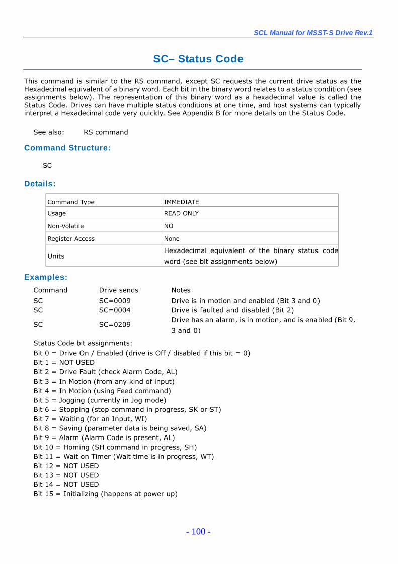
SCL Manual for MSST-S Drive Rev.1
- 100 -
SC–Status Code
This command is similar to the RS command, except SC requests the current drive status as theHexadecimal equivalent of a binary word. Each bit in the binary word relates to a status condition (seeassignments below). The representation of this binary word as a hexadecimal value is called theStatus Code. Drives can have multiple status conditions at one time, and host systems can typicallyinterpret a Hexadecimal code very quickly. See Appendix B for more details on the Status Code.
See also: RS command
Command Structure:
SC
Details:
Command Type IMMEDIATE
Usage READ ONLY
Non-Volatile NO
Register Access None
UnitsHexadecimal equivalent of the binary status code
word (see bit assignments below)
Examples:
Command Drive sends Notes
SC SC=0009 Drive is in motion and enabled (Bit 3 and 0)SC SC=0004 Drive is faulted and disabled (Bit 2)
SC SC=0209Drive has an alarm, is in motion, and is enabled (Bit 9,
3 and 0)
Status Code bit assignments:Bit 0 = Drive On / Enabled (drive is Off / disabled if this bit = 0)Bit 1 = NOT USEDBit 2 = Drive Fault (check Alarm Code, AL)Bit 3 = In Motion (from any kind of input)Bit 4 = In Motion (using Feed command)Bit 5 = Jogging (currently in Jog mode)Bit 6 = Stopping (stop command in progress, SK or ST)Bit 7 = Waiting (for an Input, WI)Bit 8 = Saving (parameter data is being saved, SA)Bit 9 = Alarm (Alarm Code is present, AL)Bit 10 = Homing (SH command in progress, SH)Bit 11 = Wait on Timer (Wait time is in progress, WT)Bit 12 = NOT USEDBit 13 = NOT USEDBit 14 = NOT USEDBit 15 = Initializing (happens at power up)
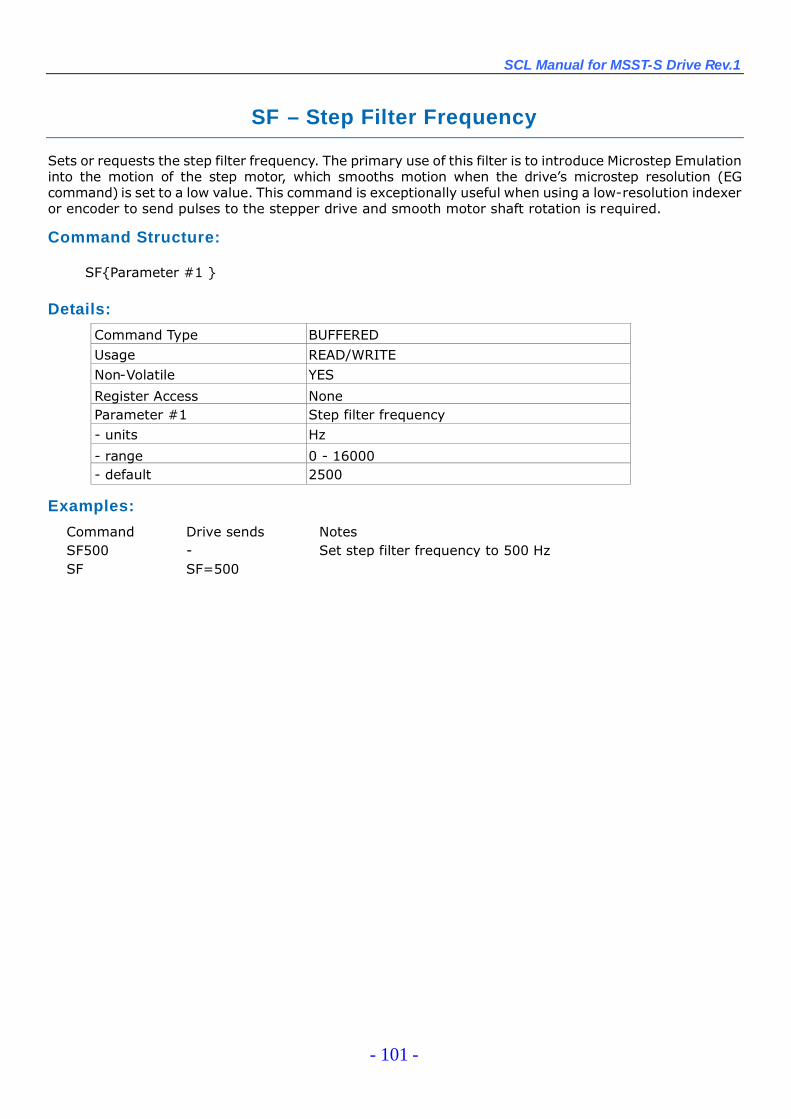
SCL Manual for MSST-S Drive Rev.1
- 101 -
SF –Step Filter Frequency
Sets or requests the step filter frequency. The primary use of this filter is to introduce Microstep Emulationinto the motion of the step motor, which smooths motion when the drive’s microstep resolution (EGcommand) is set to a low value. This command is exceptionally useful when using a low-resolution indexeror encoder to send pulses to the stepper drive and smooth motor shaft rotation is required.
Command Structure:
SF{Parameter #1 }
Details:
Command Type BUFFEREDUsage READ/WRITENon-Volatile YES
Register Access NoneParameter #1 Step filter frequency- units Hz
- range 0 - 16000- default 2500
Examples:
Command Drive sends NotesSF500 - Set step filter frequency to 500 HzSF SF=500
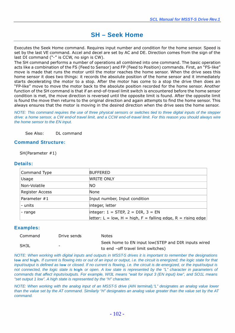
SCL Manual for MSST-S Drive Rev.1
- 102 -
SH –Seek Home
Executes the Seek Home command. Requires input number and condition for the home sensor. Speed isset by the last VE command. Accel and decel are set by AC and DE. Direction comes from the sign of thelast DI command (“-”is CCW, no sign is CW).The SH command performs a number of operations all combined into one command. The basic operationacts like a combination of the FS (Feed to Sensor) and FP (Feed to Position) commands. First, an “FS-like”move is made that runs the motor until the motor reaches the home sensor. When the drive sees thishome sensor it does two things: it records the absolute position of the home sensor and it immediatelystarts decelerating the motor to a stop. After the motor has come to a stop the drive then does an“FP-like”move to move the motor back to the absolute position recorded for the home sensor. Anotherfunction of the SH command is that if an end-of-travel limit switch is encountered before the home sensorcondition is met, the move direction is reversed until the opposite limit is found. After the opposite limitis found the move then returns to the original direction and again attempts to find the home sensor. Thisalways ensures that the motor is moving in the desired direction when the drive sees the home sensor.
NOTE: This command requires the use of three physical sensors or switches tied to three digital inputs of the stepperdrive: a home sensor, a CW end-of travel limit, and a CCW end-of-travel limit. For this reason you should always wirethe home sensor to the EN input.
See Also: DL command
Command Structure:
SH(Parameter #1)
Details:
Command Type BUFFERED
Usage WRITE ONLY
Non-Volatile NO
Register Access None
Parameter #1 Input number, Input condition
- units integer, letter
- range integer: 1 = STEP, 2 = DIR, 3 = ENletter: L = low, H = high, F = falling edge, R = rising edge
Examples:
Command Drive sends Notes
SH3L -Seek home to EN input low(STEP and DIR inputs wiredto end –off travel limit switches)
NOTE: When working with digital inputs and outputs in MSST-S drives it is important to remember the designationslow and high. If current is flowing into or out of an input or output, i.e. the circuit is energized; the logic state for thatinput/output is defined as low or closed. If no current is flowing, i.e. the circuit is de-energized, or the input/output isnot connected, the logic state is high or open. A low state is represented by the “L”character in parameters ofcommands that affect inputs/outputs. For example, WI3L means “wait for input 3 (EN input) low”, and SO1L means“set output 1 low”. A high state is represented by the “H”character.
NOTE: When working with the analog input of an MSST-S drive (AIN terminal),“L”designates an analog value lowerthan the value set by the AT command. Similarly “H”designates an analog value greater than the value set by the ATcommand.
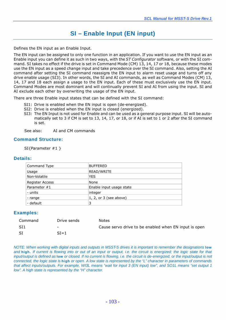
SCL Manual for MSST-S Drive Rev.1
- 103 -
SI –Enable Input (EN input)
Defines the EN input as an Enable Input.
The EN input can be assigned to only one function in an application. If you want to use the EN input as anEnable input you can define it as such in two ways, with the ST Configurator software, or with the SI com-mand. SI takes no effect if the drive is set in Command Mode (CM) 13, 14, 17 or 18, because these modesuse the EN input as a speed change input and take precedence over the SI command. Also, setting the AIcommand after setting the SI command reassigns the EN input to alarm reset usage and turns off anydrive enable usage (SI3). In other words, the SI and AI commands, as well as Command Modes (CM) 13,14, 17 and 18 each assign a usage to the EN input. Each of these must exclusively use the EN input.Command Modes are most dominant and will continually prevent SI and AI from using the input. SI andAI exclude each other by overwriting the usage of the EN input.
There are three Enable input states that can be defined with the SI command:
SI1: Drive is enabled when the EN input is open (de-energized).SI2: Drive is enabled when the EN input is closed (energized).SI3: The EN Input is not used for Enable and can be used as a general purpose input. SI will be auto-
matically set to 3 if CM is set to 13, 14, 17, or 18, or if AI is set to 1 or 2 after the SI commandis set.
See also: AI and CM commands
Command Structure:
SI{Parameter #1 }
Details:
Command Type BUFFERED
Usage READ/WRITENon-Volatile YES
Register Access NoneParameter #1 Enable input usage state
- units integer
- range 1, 2, or 3 (see above)
- default 3
Examples:
Command Drive sends Notes
SI1 - Cause servo drive to be enabled when EN input is open
SI SI=1
NOTE: When working with digital inputs and outputs in MSST-S drives it is important to remember the designations lowand high. If current is flowing into or out of an input or output, i.e. the circuit is energized; the logic state for thatinput/output is defined as low or closed. If no current is flowing, i.e. the circuit is de-energized, or the input/output is notconnected, the logic state is high or open. A low state is represented by the “L”character in parameters of commandsthat affect inputs/outputs. For example, WI3L means “wait for input 3 (EN input) low”, and SO1L means “set output 1low”. A high state is represented by the “H”character.
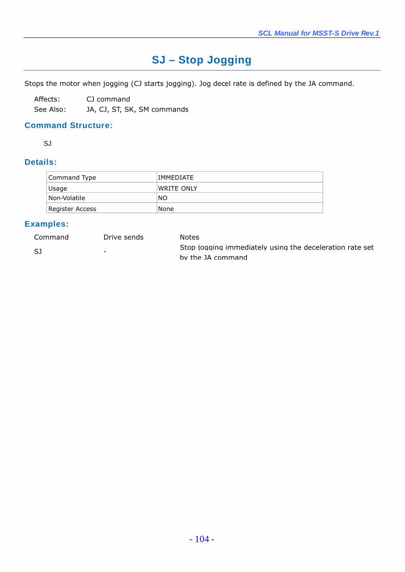
SCL Manual for MSST-S Drive Rev.1
- 104 -
SJ –Stop Jogging
Stops the motor when jogging (CJ starts jogging). Jog decel rate is defined by the JA command.
Affects: CJ commandSee Also: JA, CJ, ST, SK, SM commands
Command Structure:
SJ
Details:
Command Type IMMEDIATE
Usage WRITE ONLY
Non-Volatile NO
Register Access None
Examples:
Command Drive sends Notes
SJ - Stop jogging immediately using the deceleration rate setby the JA command

SCL Manual for MSST-S Drive Rev.1
- 105 -
SK –Stop & Kill Buffer
Halts any buffered command in progress and erases all buffered commands in the command buffer.When used to stop a move deceleration rate is controlled by the AM (Max Acceleration) parameter. If the“D”parameter is used deceleration rate is controlled by either DE (with “Feed”moves like FL, FP, SH) orJA (when jogging).
Affects: Motion and command buffer contents
See Also: AM and ST commands
Command Structure:
SK{Parameter #1}
Details:
Command Type IMMEDIATE
Usage WRITE ONLY
Non-Volatile NO
Register Access None
Parameter #1 Deceleration rate
- units letter
- range D = deceleration rate set by DE or JA command
no parameter = deceleration rate set by AM command
Examples:
Command Drive sends Notes
SK -Stop motion immediately using the deceleration rate setby the AM command and erase the contents of the
command buffer
SKD -Stop motion immediately using the deceleration rate setby the DE command (or JA if jogging) and erase the
contents of the command buffer
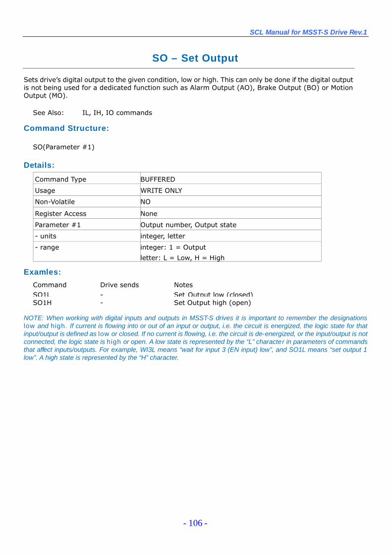
SCL Manual for MSST-S Drive Rev.1
- 106 -
SO – Set Output
Sets drive’s digital output to the given condition, low or high. This can only be done if the digital outputis not being used for a dedicated function such as Alarm Output (AO), Brake Output (BO) or MotionOutput (MO).
See Also: IL, IH, IO commands
Command Structure:
SO(Parameter #1)
Details:
Command Type BUFFERED
Usage WRITE ONLY
Non-Volatile NO
Register Access None
Parameter #1 Output number, Output state
- units integer, letter
- range integer: 1 = Output
letter: L = Low, H = High
Examles:
Command Drive sends NotesSO1L - Set Output low (closed)SO1H - Set Output high (open)
NOTE: When working with digital inputs and outputs in MSST-S drives it is important to remember the designationslow and high. If current is flowing into or out of an input or output, i.e. the circuit is energized, the logic state for thatinput/output is defined as low or closed. If no current is flowing, i.e. the circuit is de-energized, or the input/output is notconnected, the logic state is high or open. A low state is represented by the “L”character in parameters of commandsthat affect inputs/outputs. For example, WI3L means “wait for input 3 (EN input) low”, and SO1L means “set output 1low”. A high state is represented by the “H”character.
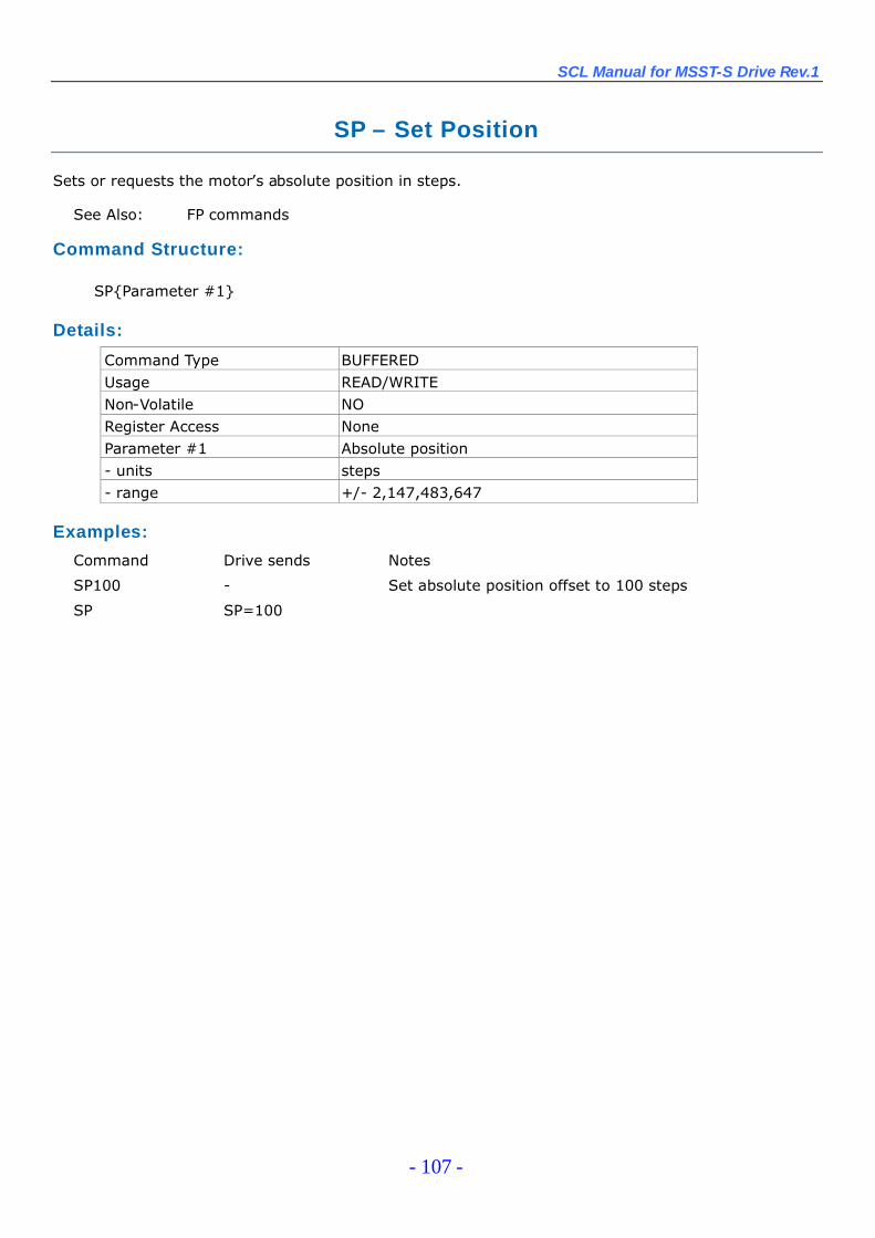
SCL Manual for MSST-S Drive Rev.1
- 107 -
SP – Set Position
Sets or requests the motor’s absolute position in steps.
See Also: FP commands
Command Structure:
SP{Parameter #1}
Details:
Command Type BUFFEREDUsage READ/WRITENon-Volatile NORegister Access NoneParameter #1 Absolute position- units steps- range +/- 2,147,483,647
Examples:
Command Drive sends Notes
SP100 - Set absolute position offset to 100 steps
SP SP=100
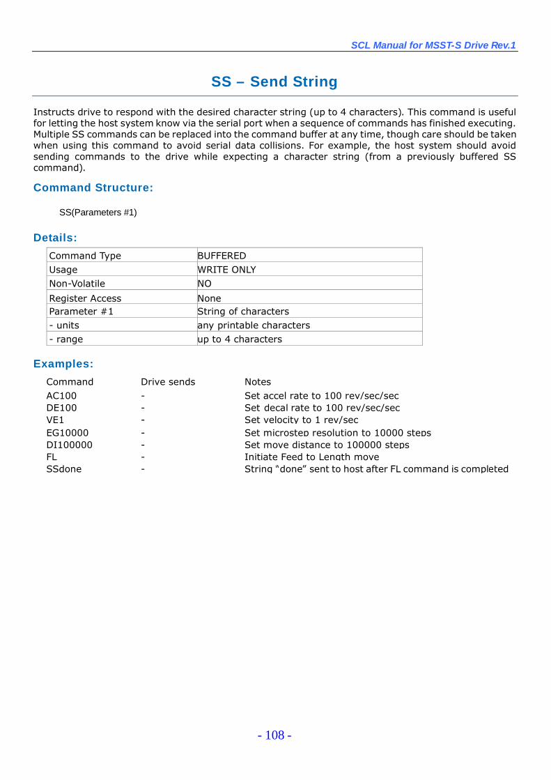
SCL Manual for MSST-S Drive Rev.1
- 108 -
SS – Send String
Instructs drive to respond with the desired character string (up to 4 characters). This command is usefulfor letting the host system know via the serial port when a sequence of commands has finished executing.Multiple SS commands can be replaced into the command buffer at any time, though care should be takenwhen using this command to avoid serial data collisions. For example, the host system should avoidsending commands to the drive while expecting a character string (from a previously buffered SScommand).
Command Structure:
SS(Parameters #1)
Details:
Command Type BUFFEREDUsage WRITE ONLYNon-Volatile NO
Register Access NoneParameter #1 String of characters- units any printable characters- range up to 4 characters
Examples:
Command Drive sends NotesAC100 - Set accel rate to 100 rev/sec/secDE100 - Set decal rate to 100 rev/sec/secVE1 - Set velocity to 1 rev/secEG10000 - Set microstep resolution to 10000 stepsDI100000 - Set move distance to 100000 stepsFL - Initiate Feed to Length moveSSdone - String “done”sent to host after FL command is completed
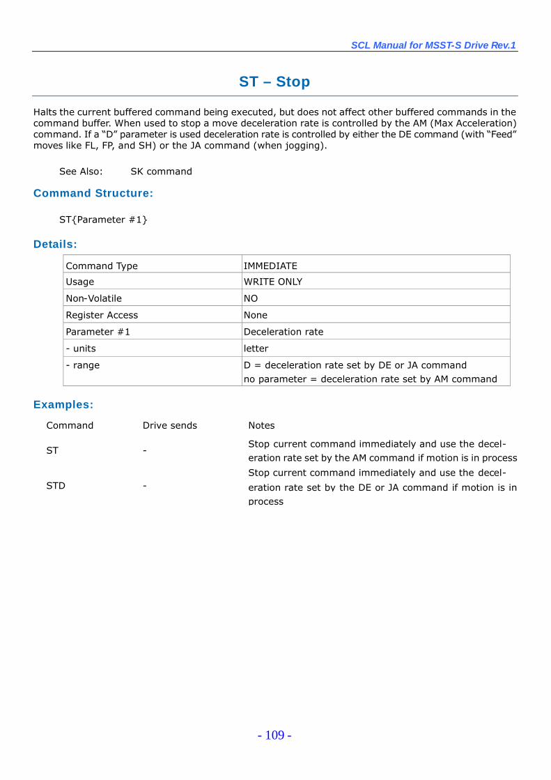
SCL Manual for MSST-S Drive Rev.1
- 109 -
ST –Stop
Halts the current buffered command being executed, but does not affect other buffered commands in thecommand buffer. When used to stop a move deceleration rate is controlled by the AM (Max Acceleration)command. If a “D”parameter is used deceleration rate is controlled by either the DE command (with “Feed”moves like FL, FP, and SH) or the JA command (when jogging).
See Also: SK command
Command Structure:
ST{Parameter #1}
Details:
Command Type IMMEDIATE
Usage WRITE ONLY
Non-Volatile NO
Register Access None
Parameter #1 Deceleration rate
- units letter
- range D = deceleration rate set by DE or JA commandno parameter = deceleration rate set by AM command
Examples:
Command Drive sends Notes
ST -Stop current command immediately and use the decel-eration rate set by the AM command if motion is in process
STD -Stop current command immediately and use the decel-
eration rate set by the DE or JA command if motion is inprocess
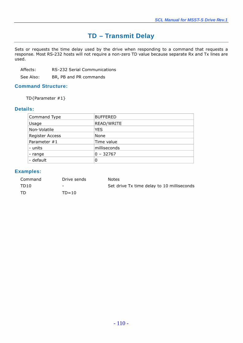
SCL Manual for MSST-S Drive Rev.1
- 110 -
TD –Transmit Delay
Sets or requests the time delay used by the drive when responding to a command that requests aresponse. Most RS-232 hosts will not require a non-zero TD value because separate Rx and Tx lines areused.
Affects: RS-232 Serial Communications
See Also: BR, PB and PR commands
Command Structure:
TD{Parameter #1}
Details:
Command Type BUFFERED
Usage READ/WRITENon-Volatile YESRegister Access NoneParameter #1 Time value- units milliseconds- range 0 –32767- default 0
Examples:
Command Drive sends Notes
TD10 - Set drive Tx time delay to 10 milliseconds
TD TD=10
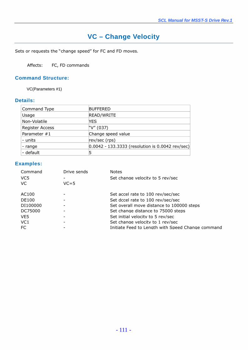
SCL Manual for MSST-S Drive Rev.1
- 111 -
VC –Change Velocity
Sets or requests the “change speed”for FC and FD moves.
Affects: FC, FD commands
Command Structure:
VC(Parameters #1)
Details:
Command Type BUFFEREDUsage READ/WRITENon-Volatile YESRegister Access “V”(037)Parameter #1 Change speed value- units rev/sec (rps)- range 0.0042 - 133.3333 (resolution is 0.0042 rev/sec)- default 5
Examples:
Command Drive sends NotesVC5 - Set change velocity to 5 rev/secVC VC=5
AC100 - Set accel rate to 100 rev/sec/secDE100 - Set dccel rate to 100 rev/sec/secDI100000 - Set overall move distance to 100000 stepsDC75000 - Set change distance to 75000 stepsVE5 - Set initial velocity to 5 rev/secVC1 - Set change velocity to 1 rev/secFC - Initiate Feed to Length with Speed Change command
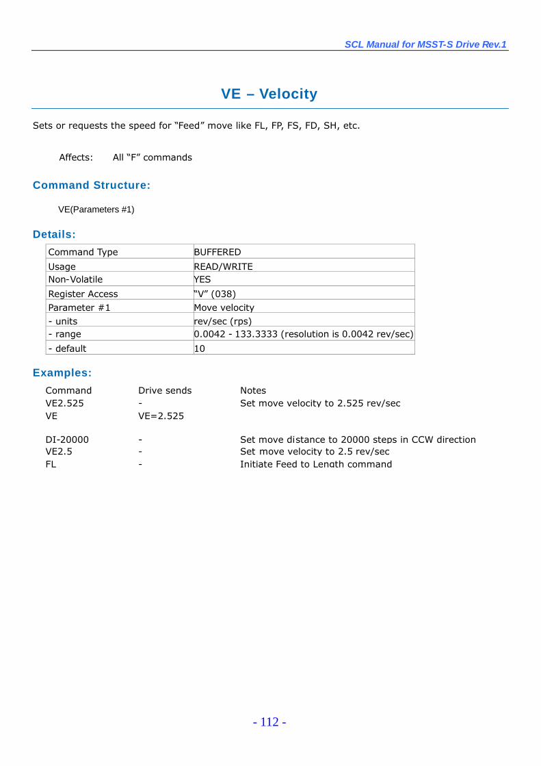
SCL Manual for MSST-S Drive Rev.1
- 112 -
VE –Velocity
Sets or requests the speed for “Feed”move like FL, FP, FS, FD, SH, etc.
Affects: All “F”commands
Command Structure:
VE(Parameters #1)
Details:
Command Type BUFFERED
Usage READ/WRITENon-Volatile YES
Register Access “V”(038)Parameter #1 Move velocity- units rev/sec (rps)- range 0.0042 - 133.3333 (resolution is 0.0042 rev/sec)
- default 10
Examples:
Command Drive sends NotesVE2.525 - Set move velocity to 2.525 rev/secVE VE=2.525
DI-20000 - Set move distance to 20000 steps in CCW directionVE2.5 - Set move velocity to 2.5 rev/secFL - Initiate Feed to Length command
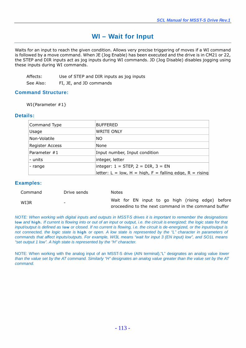
SCL Manual for MSST-S Drive Rev.1
- 113 -
WI – Wait for Input
Waits for an input to reach the given condition. Allows very precise triggering of moves if a WI commandis followed by a move command. When JE (Jog Enable) has been executed and the drive is in CM21 or 22,the STEP and DIR inputs act as jog inputs during WI commands. JD (Jog Disable) disables jogging usingthese inputs during WI commands.
Affects: Use of STEP and DIR inputs as jog inputs
See Also: FI, JE, and JD commands
Command Structure:
WI{Parameter #1}
Details:
Command Type BUFFERED
Usage WRITE ONLY
Non-Volatile NO
Register Access None
Parameter #1 Input number, Input condition
- units integer, letter
- range integer: 1 = STEP, 2 = DIR, 3 = EN
letter: L = low, H = high, F = falling edge, R = rising
Examples:
Command Drive sends Notes
WI3R - Wait for EN input to go high (rising edge) beforeproceeding to the next command in the command buffer
NOTE: When working with digital inputs and outputs in MSST-S drives it is important to remember the designationslow and high. If current is flowing into or out of an input or output, i.e. the circuit is energized; the logic state for thatinput/output is defined as low or closed. If no current is flowing, i.e. the circuit is de-energized, or the input/output isnot connected, the logic state is high or open. A low state is represented by the “L”character in parameters ofcommands that affect inputs/outputs. For example, WI3L means “wait for input 3 (EN input) low”, and SO1L means“set output 1 low”. A high state is represented by the “H”character.
NOTE: When working with the analog input of an MSST-S drive (AIN terminal),“L”designates an analog value lowerthan the value set by the AT command. Similarly “H”designates an analog value greater than the value set by the ATcommand.
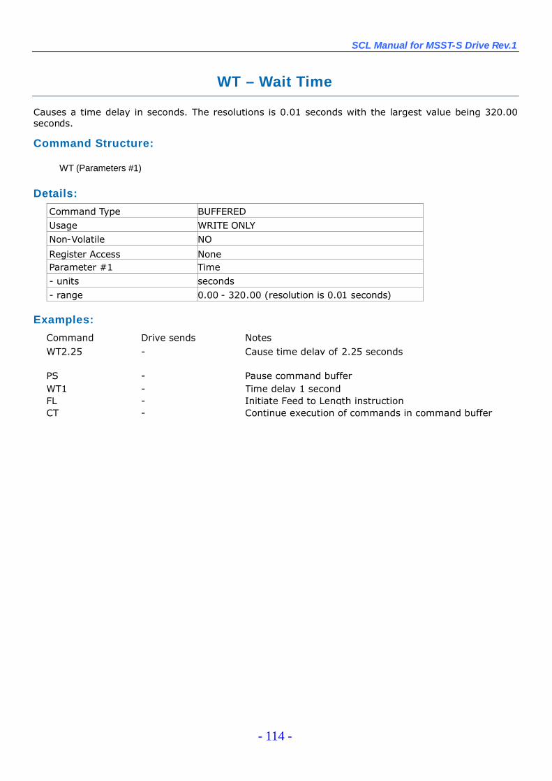
SCL Manual for MSST-S Drive Rev.1
- 114 -
WT –Wait Time
Causes a time delay in seconds. The resolutions is 0.01 seconds with the largest value being 320.00seconds.
Command Structure:
WT (Parameters #1)
Details:
Command Type BUFFEREDUsage WRITE ONLYNon-Volatile NO
Register Access NoneParameter #1 Time- units seconds- range 0.00 - 320.00 (resolution is 0.01 seconds)
Examples:
Command Drive sends NotesWT2.25 - Cause time delay of 2.25 seconds
PS - Pause command bufferWT1 - Time delay 1 secondFL - Initiate Feed to Length instructionCT - Continue execution of commands in command buffer

SCL Manual for MSST-S Drive Rev.1
- 115 -
Data RegistersMany of the commands listed in this reference function by transferring data to a drive for later use.
These values are stored in data registers within the drive and remain there until new commands changethe values, or until power is removed from the drive. For example, if you send the Velocity command “VE10”, a maximum move speed of 10 rev/sec is placed in the data register for velocity. You can then execute asmany Feed to Length (FL), Feed to Position (FP) and Feed to Sensor (FS) commands as you’d like withoutsending another VE command: the move speed of 10 rev/sec will remain in the velocity data register untilyou change it or until power is removed from the drive.
In addition to the data register for velocity, there are registers for move acceleration (AC command,“A”register), deceleration (DE command, “B”register) and move distance (DI command, “D”register).There are also registers for limit sensors (DL command), motor current (CC command), motor resolution(EG command), and motor position (SP command). See the following section on Data RegisterAssignments for a complete listing of data registers available in your drive.
Not all commands function by transferring a data value into a register. Conversely, not all dataregisters are associated with a command. To access data registers that are not associated with acommand, you can use a register’s unique character assignment. See the Data Register Assignments onthe following pages for a listing of data registers and their character assignments. When accessing a dataregister using its character assignment you use the RL (Register Load IMMEDIATE) or RX (Register LoadBUFFERED) commands. These commands allow you to load data values into a register as well as readback the contents of a data register. For example, we set the move speed to 10 rev/sec by using thevelocity command “VE1 0”. You can accomplish the same thing by using the RL command and thecharacter assignment for the velocity data register, “V”. By sending “RLV2400”to the drive you set themove speed to 10 rev/sec. Wait, please read that again: send “RLV2400”to change the velocity to 10rev/sec? Be careful of units when working directly with registers and the RL and RX commands. Dataregister units are often not the same as the units used by their associated commands. The VE commandworks in rev/sec, but the “V”register works in “deca-rpm/sec”(10 rpm/sec). This means you multiply thedesired speed in rev/sec by 240 to get the same value in “deca-rpm/ sec”.
There are two basic types of data registers available in MSST-S drives: Read-Only and Read/Write
Read-Only data registersRead-Only data registers are predefined registers that contain information about drive parameters,
settings, and states. These include registers for commanded current, analog input level, drivetemperature, internal bus voltage, and more. You cannot transfer data values to a Read-Only dataregister; you can only read the contents of them (see RL and RX commands). Read-Only registers areassigned to lower-case letters.
Read/Write data registersRead/Write data registers are predefined registers that contain drive and move parameters that can
be set by the user. These parameters include acceleration rate, velocity, move distance, current setting,and more. Many of the Read/Write registers are associated with a particular command, so you can readtheir contents or load data into them with RL, RX, or that parameter’s particular command. Read/Writeregisters are assigned to upper-case letters.
Data Registers AssignmentWhat follows is a listing of all the data registers available with your MSST-S drive. In the tables
below,"Ch." denotes the data register’s character assignment, and “Description”gives the name of thedata register. The column “3-digit”denotes the register’s 3-digit numeric assignment (see PR command);“Data Type”designates whether the data register is a 16-bit word (Short) or a 32-bit word (Long); “Units”shows how a data register’s contents are used by the drive; and, “Default”shows the value loaded intothe register at the factory. Also, some registers are followed by specific notes helpful for using them.
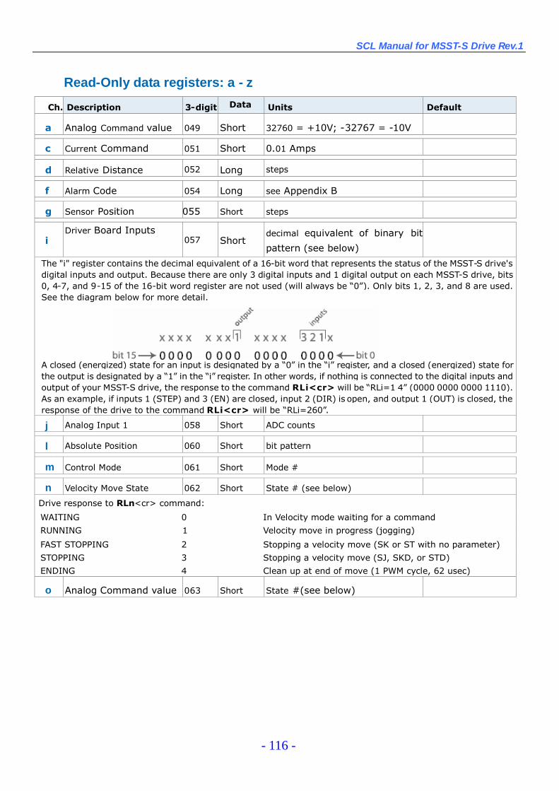
SCL Manual for MSST-S Drive Rev.1
- 116 -
Read-Only data registers: a - z
Ch. Description 3-digit Data
TypeUnits Default
a Analog Command value 049 Short 32760 = +10V; -32767 = -10V
c Current Command 051 Short 0.01 Amps
d Relative Distance 052 Long steps
f Alarm Code 054 Long see Appendix B
g Sensor Position 055 Short steps
iDriver Board Inputs
057 Shortdecimal equivalent of binary bit
pattern (see below)
The "i" register contains the decimal equivalent of a 16-bit word that represents the status of the MSST-S drive'sdigital inputs and output. Because there are only 3 digital inputs and 1 digital output on each MSST-S drive, bits0, 4-7, and 9-15 of the 16-bit word register are not used (will always be “0”). Only bits 1, 2, 3, and 8 are used.See the diagram below for more detail.
A closed (energized) state for an input is designated by a “0”in the “i”register, and a closed (energized) state forthe output is designated by a “1”in the “i”register. In other words, if nothing is connected to the digital inputs andoutput of your MSST-S drive, the response to the command RLi<cr> will be “RLi=1 4”(0000 0000 0000 1110).As an example, if inputs 1 (STEP) and 3 (EN) are closed, input 2 (DIR) is open, and output 1 (OUT) is closed, theresponse of the drive to the command RLi<cr> will be “RLi=260”.
j Analog Input 1 058 Short ADC counts
l Absolute Position 060 Short bit pattern
m Control Mode 061 Short Mode #
n Velocity Move State 062 Short State # (see below)
Drive response to RLn<cr> command:
WAITING 0 In Velocity mode waiting for a command
RUNNING 1 Velocity move in progress (jogging)
FAST STOPPING 2 Stopping a velocity move (SK or ST with no parameter)
STOPPING 3 Stopping a velocity move (SJ, SKD, or STD)
ENDING 4 Clean up at end of move (1 PWM cycle, 62 usec)
o Analog Command value 063 Short State #(see below)
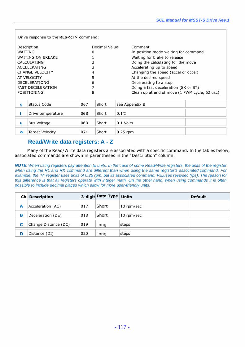
SCL Manual for MSST-S Drive Rev.1
- 117 -
Drive response to the RLo<cr> command:
Description Decimal Value CommentWAITING 0 In position mode waiting for commandWAITING ON BREAKE 1 Waiting for brake to releaseCALCULATING 2 Doing the calculating for the moveACCELERATING 3 Accelerating up to speedCHANGE VELOCITY 4 Changing the speed (accel or dccel)AT VELOCITY 5 At the desired speedDECELERATIONG 6 Decelerating to a stopFAST DECELERATION 7 Doing a fast deceleration (SK or ST)POSITIONING 8 Clean up at end of move (1 PWM cycle, 62 usc)
s Status Code 067 Short see Appendix B
t Drive temperature 068 Short 0.1℃
u Bus Voltage 069 Short 0.1 Volts
w Target Velocity 071 Short 0.25 rpm
Read/Write data registers: A - ZMany of the Read/Write data registers are associated with a specific command. In the tables below,
associated commands are shown in parentheses in the “Description”column.
NOTE: When using registers pay attention to units. In the case of some Read/Write registers, the units of the registerwhen using the RL and RX command are different than when using the same register’s associated command. Forexample, the “V”register uses units of 0.25 rpm, but its associated command, VE,uses revs/sec (rps). The reason forthis difference is that all registers operate with integer math. On the other hand, when using commands it is oftenpossible to include decimal places which allow for more user-friendly units.
Ch. Description 3-digit Data Type
TypeType
Units Default
A Acceleration (AC) 017 Short 10 rpm/sec
B Deceleration (DE) 018 Short 10 rpm/sec
C Change Distance (DC) 019 Long steps
D Distance (DI) 020 Long steps

SCL Manual for MSST-S Drive Rev.1
- 118 -
F Other Flags 022 Long bit pattern (see below)
Drive response to RLF<cr> command:
Description Hex Value Decimal ValueDISTANCE LIMIT FLAG 0x0001 1SENSOR FOUND FLAG 0x0002 2HARDWARE OVERCURRENT 0x0004 4SOFTWARE OVERCURRENT 0x0008 8BAD CURRENT OFFSET –Ph. A 0x0010 16BAD CURRENT OFFSET –Ph. A 0x0020 32OPEN WINDING –Phase A 0x0040 64OPEN WINDING –Phase B 0x0080 128
Note: Clear flags by sending RLF0<cr> command to the drive
H RESERVED 024 Long
J Jog Velocity (JS) 026 Short 0.25 rpm
K Jog Acceleration (JA) 027 Short 10 rpm/sec
L Jog Deceleration (JL) 028 Short 10 rpm/sec
NContinuous Current/Change
Current030 Short 0.01 Amps
O Peak Current/Idle Current 031 Short 0.01 Amps
P Absolute Position Command 032 Long Steps
Q RESERVED 033 Long
R Steps per Rev (EG) 034 Short Steps/rev
S Actual Step Position 035 Long Steps
U Change Velocity (VC) 037 Short 0.25 rpm
V Velocity (VE) 038 Short 0.25 rpm
X Analog Position Gain (AP) 040 Short ADC counts/count
Y Analog threshold (AT) 041 Short ADC counts
Z Analog Offset (AO) 042 Short 0.001 Volts
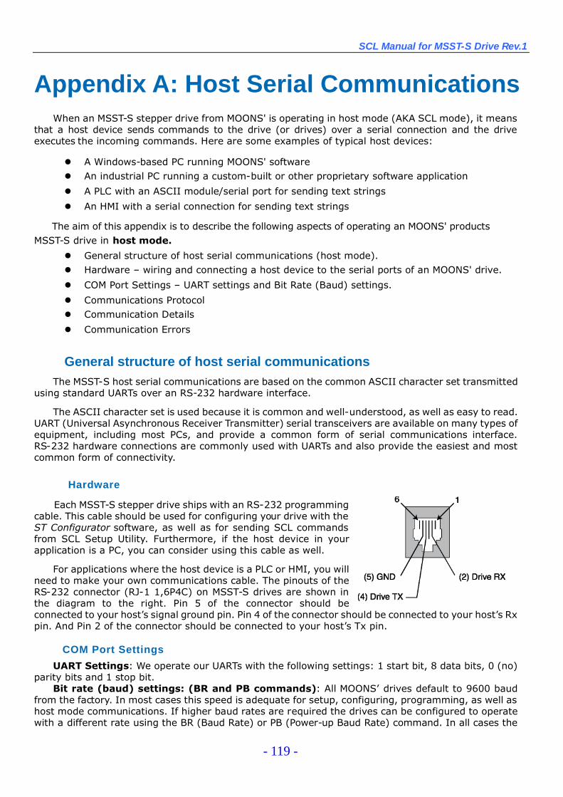
SCL Manual for MSST-S Drive Rev.1
- 119 -
Appendix A: Host Serial CommunicationsWhen an MSST-S stepper drive from MOONS' is operating in host mode (AKA SCL mode), it means
that a host device sends commands to the drive (or drives) over a serial connection and the driveexecutes the incoming commands. Here are some examples of typical host devices:
A Windows-based PC running MOONS' software An industrial PC running a custom-built or other proprietary software application
A PLC with an ASCII module/serial port for sending text strings
An HMI with a serial connection for sending text strings
The aim of this appendix is to describe the following aspects of operating an MOONS' productsMSST-S drive in host mode.
General structure of host serial communications (host mode). Hardware –wiring and connecting a host device to the serial ports of an MOONS' drive.
COM Port Settings –UART settings and Bit Rate (Baud) settings.
Communications Protocol Communication Details
Communication Errors
General structure of host serial communicationsThe MSST-S host serial communications are based on the common ASCII character set transmitted
using standard UARTs over an RS-232 hardware interface.
The ASCII character set is used because it is common and well-understood, as well as easy to read.UART (Universal Asynchronous Receiver Transmitter) serial transceivers are available on many types ofequipment, including most PCs, and provide a common form of serial communications interface.RS-232 hardware connections are commonly used with UARTs and also provide the easiest and mostcommon form of connectivity.
Hardware
Each MSST-S stepper drive ships with an RS-232 programmingcable. This cable should be used for configuring your drive with theST Configurator software, as well as for sending SCL commandsfrom SCL Setup Utility. Furthermore, if the host device in yourapplication is a PC, you can consider using this cable as well.
For applications where the host device is a PLC or HMI, you willneed to make your own communications cable. The pinouts of theRS-232 connector (RJ-1 1,6P4C) on MSST-S drives are shown inthe diagram to the right. Pin 5 of the connector should beconnected to your host’s signal ground pin. Pin 4 of the connector should be connected to your host’s Rxpin. And Pin 2 of the connector should be connected to your host’s Tx pin.
COM Port Settings
UART Settings: We operate our UARTs with the following settings: 1 start bit, 8 data bits, 0 (no)parity bits and 1 stop bit.
Bit rate (baud) settings: (BR and PB commands): All MOONS’drives default to 9600 baudfrom the factory. In most cases this speed is adequate for setup, configuring, programming, as well ashost mode communications. If higher baud rates are required the drives can be configured to operatewith a different rate using the BR (Baud Rate) or PB (Power-up Baud Rate) command. In all cases the
SCL Manual for MSST-S Drive Rev.1
- 120 -
drive starts up at the factory rate, 9600, and will remain there if the “power-up packet”is acknowledgedby the host (see “Drive Startup”below). When the power-up cycle is complete and if the drive has notreceived the power-up packet, the drive will activate the new baud rate.
Selecting a baud rate higher than the default 9600 is dependent on the application. If there is a hostdevice operating a number of drives on a network, a higher speed may be required in order to processall the communication needs.
Communications Protocol
In general, the protocol for communications between a host device and a drive is quite simple.MSST-S drives do not initiate communications on their own, so drives are normally in a state to receivepackets from the host. A communications packet, or packet for short, includes all the charactersrequired to complete a command (host to drive) or response (drive to host) transmission. In otherwords, a host initiates communication by sending a command packet, and the drive responds to thatcommand by sending a response packet back to the host.
Command Transmission (host to drive): The philosophy of sending characters to the driverequires the host to send all the required characters that form a packet in a limited time frame. At thestart of receiving a packet, the drive begins timing the space between characters. Each time a characteris received an internal timer is reset to 200 milliseconds. If the timer reaches zero before the nextcharacter in the packet is received the drive will terminate its packet parsing (characters will still go intothe receive buffer) and may send out an error response packet depending on the protocol setting. Thepurpose of the timeout feature is to allow the drive to purge its buffers automatically when a badtransmission occurs.
NOTE: This timeout feature limits the usage of host devices such as the Windows application HyperTerminal.We recommend using MOONS' SCL Setup Utility instead. This utility sends out an entire command packet withthe minimum delay between characters, and includes the packet’s terminating character.
Response Transmission (drive to host): In response to a command packet from the host adrive will usually send a response packet. The drive sends out its entire response packet with verylimited space between characters. At 9600 baud rate the space between characters is less then 1 bitspace (0.0001 seconds). The host system must be able to handle this speed. The space betweencharacters can vary depending on the settings of the PR command (see below).
Protocol Settings (PR Command): The PR (Protocol) command offers users the ability to addvarious features to the overall communications protocol, i.e. tailor the structure of command andresponse packets to best fit the needs of their application. In general, when a host device sends acommand packet to a drive, the drive will either understand the command or not. If the driveunderstands the command the drive executes the command. If the drive doesn’t understand thecommand it cannot execute the command. In most cases the host device will want to know whether thedrive has understood the command or not, and so the drive can be set to automatically send anAcknowledge (understood) or Negative Acknowledge (not understand) response packet to the host.
Along with Acknowledge/Negative Acknowledge (Ack/Nack), the PR command controls a number ofother protocol settings (see PR command). Also, the PR command controls whether or not the drive willrespond with error codes in the response packet when communications errors occur.
Communication Details
Transmit Delay: (TD Command): The TD command allows users to define a dwell time in a drive,which is used by the drive to delay the start of transmission of a response packet after the end ofreception of a command packet.
NOTE: The Transmit Delay (TD) command is intended for use in 2-wire RS-485 serial communicationnetworks. Because the MSST-S drives only have RS-232 ports for serial communications, setting the TD commandto a non-zero value is unnecessary.
Communications Packet: A Communications Packet, or packet for short, includes all thecharacters required to complete a command or response transmission. This can vary depending on the

SCL Manual for MSST-S Drive Rev.1
- 121 -
settings of the PR command. See the PR command for more details.
Drive Startup: At power-up, all MOONS' drives send out what is called the “power-up packet”. Thispacket notifies a host of the drive’s presence. After sending the power-up packet the drive waits for aresponse from the host. This is one of the rare instances in which a drive will initiate communications withthe host. This process is necessary for a number of MOONS' software applications such as MisProgrammer and ST Configurator. The power-up packet is an exception to the ASCII character rulein that all the characters in the packet are binary value. The power-up packet consists of three binarycharacters with the first character being a binary 255 (255 is not a printable ASCII character). Thischaracter designates to the software application that the packet is a power-up packet. The following twocharacters are the firmware version number and the model number of the drive, respectively.
Power-Up Packet = (255)(F/W Version)(Model No.)
As an example, an MSST-S drive with f/w version 1.53 will send out a power-up packet that lookslike this: (255)(53)(38). To an ASCII terminal this packet may look like “ÿ5&”. The (255) is thepower-up packet designator, the (53) actually stands for f/w version 1.53 (the “1”is implied), and the(38) is an internal model number for the drive.
The power-up packet is always sent at 9600 baud, regardless of the bit rate set by the BR or PBcommand. If an MOONS' software application is present it will respond to the power-up packet andcommunications will continue at 9600 baud. If an MOONS' software application is not present, thedrive’s request made by the power-up packet will time-out and the drive will begin communicating atthe saved bit rate (BR or PB command), 9600 or otherwise.
Communication Errors
During the process of sending communication packets between the host and drive(s), twodifferent types of communication errors can occur.
Hardware errors: Hardware errors are displayed physically by an MSST-S drive via the red andgreen LEDs on the drive, (see Appendix B), but no response packet is automatically generated fromthe drive to the host. Therefore it is the responsibility of the host to check for hardwarecommunication errors using the AL, RS, and/or SC commands. See AL and SC commands for moredetails. Once the host has determined the presence of a hardware communication error, the nature ofthe error can be retrieved using the CE command.
Parsing errors: Parsing errors happen when a drive receives a command packet but cannotproperly interpret (parse) the command. Parsing errors can automatically generate a response packetfrom the drive to the host, depending on the settings of the PR command (see PR command, Bit 2).
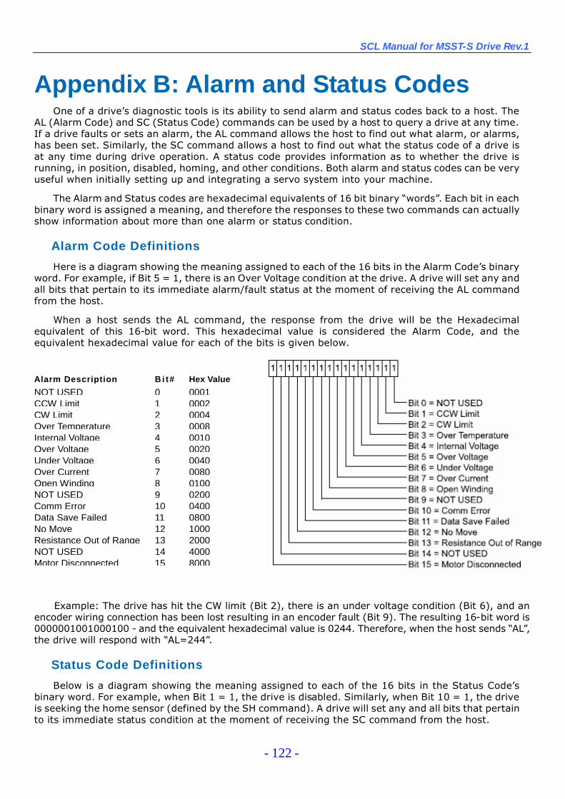
SCL Manual for MSST-S Drive Rev.1
- 122 -
Appendix B: Alarm and Status CodesOne of a drive’s diagnostic tools is its ability to send alarm and status codes back to a host. The
AL (Alarm Code) and SC (Status Code) commands can be used by a host to query a drive at any time.If a drive faults or sets an alarm, the AL command allows the host to find out what alarm, or alarms,has been set. Similarly, the SC command allows a host to find out what the status code of a drive isat any time during drive operation. A status code provides information as to whether the drive isrunning, in position, disabled, homing, and other conditions. Both alarm and status codes can be veryuseful when initially setting up and integrating a servo system into your machine.
The Alarm and Status codes are hexadecimal equivalents of 16 bit binary “words”. Each bit in eachbinary word is assigned a meaning, and therefore the responses to these two commands can actuallyshow information about more than one alarm or status condition.
Alarm Code Definitions
Here is a diagram showing the meaning assigned to each of the 16 bits in the Alarm Code’s binaryword. For example, if Bit 5 = 1, there is an Over Voltage condition at the drive. A drive will set any andall bits that pertain to its immediate alarm/fault status at the moment of receiving the AL commandfrom the host.
When a host sends the AL command, the response from the drive will be the Hexadecimalequivalent of this 16-bit word. This hexadecimal value is considered the Alarm Code, and theequivalent hexadecimal value for each of the bits is given below.
Example: The drive has hit the CW limit (Bit 2), there is an under voltage condition (Bit 6), and anencoder wiring connection has been lost resulting in an encoder fault (Bit 9). The resulting 16-bit word is0000001001000100 - and the equivalent hexadecimal value is 0244. Therefore, when the host sends “AL”,the drive will respond with “AL=244”.
Status Code Definitions
Below is a diagram showing the meaning assigned to each of the 16 bits in the Status Code’sbinary word. For example, when Bit 1 = 1, the drive is disabled. Similarly, when Bit 10 = 1, the driveis seeking the home sensor (defined by the SH command). A drive will set any and all bits that pertainto its immediate status condition at the moment of receiving the SC command from the host.
Alarm Description Bi t# Hex Value
NOT USED 0 0001CCW Limit 1 0002CW Limit 2 0004Over Temperature 3 0008Internal Voltage 4 0010Over Voltage 5 0020Under Voltage 6 0040Over Current 7 0080Open Winding 8 0100NOT USED 9 0200Comm Error 10 0400Data Save Failed 11 0800No Move 12 1000Resistance Out of Range 13 2000NOT USED 14 4000Motor Disconnected 15 8000
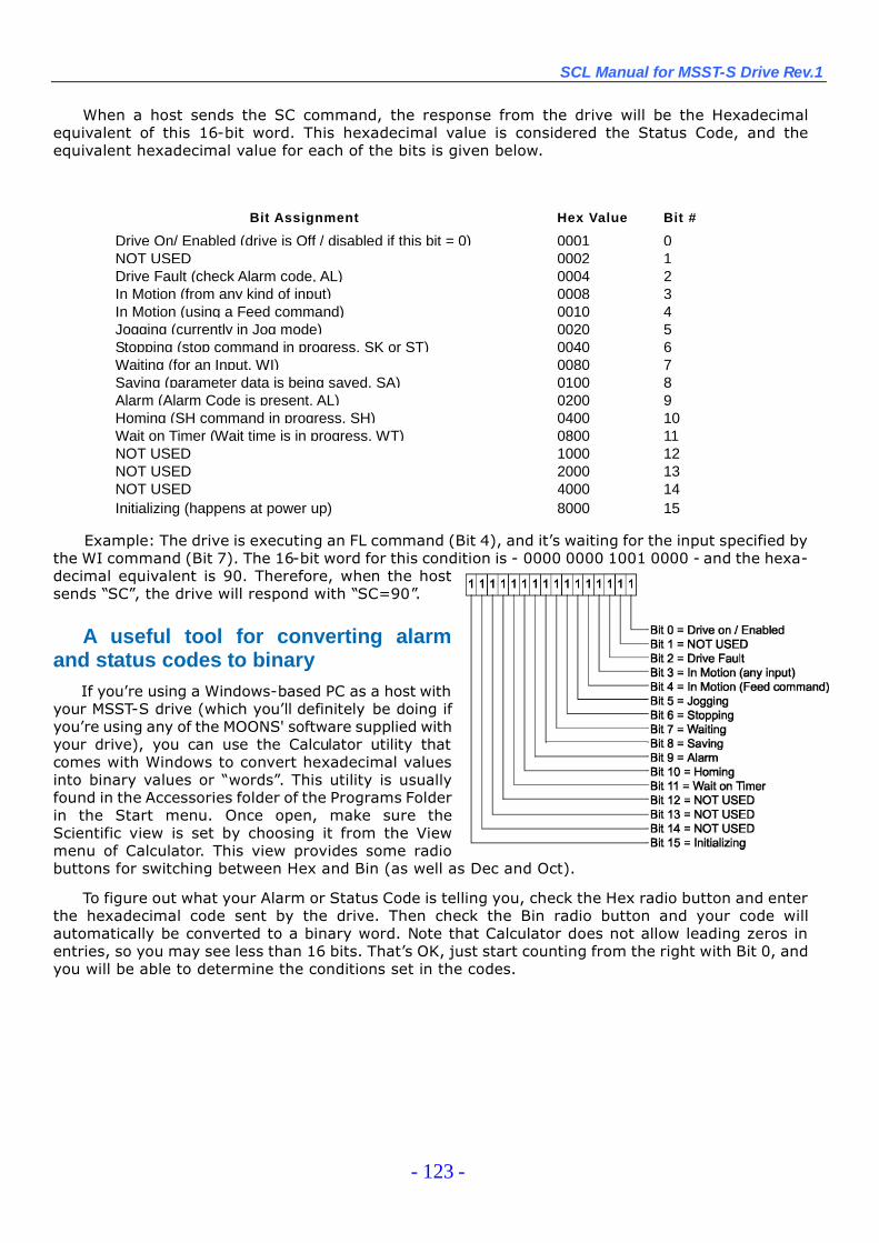
SCL Manual for MSST-S Drive Rev.1
- 123 -
When a host sends the SC command, the response from the drive will be the Hexadecimalequivalent of this 16-bit word. This hexadecimal value is considered the Status Code, and theequivalent hexadecimal value for each of the bits is given below.
Example: The drive is executing an FL command (Bit 4), and it’s waiting for the input specified bythe WI command (Bit 7). The 16-bit word for this condition is - 0000 0000 1001 0000 - and the hexa-decimal equivalent is 90. Therefore, when the hostsends “SC”, the drive will respond with “SC=90”.
A useful tool for converting alarmand status codes to binary
If you’re using a Windows-based PC as a host withyour MSST-S drive (which you’ll definitely be doing ifyou’re using any of the MOONS' software supplied withyour drive), you can use the Calculator utility thatcomes with Windows to convert hexadecimal valuesinto binary values or “words”. This utility is usuallyfound in the Accessories folder of the Programs Folderin the Start menu. Once open, make sure theScientific view is set by choosing it from the Viewmenu of Calculator. This view provides some radiobuttons for switching between Hex and Bin (as well as Dec and Oct).
To figure out what your Alarm or Status Code is telling you, check the Hex radio button and enterthe hexadecimal code sent by the drive. Then check the Bin radio button and your code willautomatically be converted to a binary word. Note that Calculator does not allow leading zeros inentries, so you may see less than 16 bits. That’s OK, just start counting from the right with Bit 0, andyou will be able to determine the conditions set in the codes.
Bit Assignment Hex Value Bit #
Drive On/ Enabled (drive is Off / disabled if this bit = 0) 0001 0NOT USED 0002 1Drive Fault (check Alarm code, AL) 0004 2In Motion (from any kind of input) 0008 3In Motion (using a Feed command) 0010 4Jogging (currently in Jog mode) 0020 5Stopping (stop command in progress, SK or ST) 0040 6Waiting (for an Input, WI) 0080 7Saving (parameter data is being saved, SA) 0100 8Alarm (Alarm Code is present, AL) 0200 9Homing (SH command in progress, SH) 0400 10Wait on Timer (Wait time is in progress, WT) 0800 11NOT USED 1000 12NOT USED 2000 13NOT USED 4000 14Initializing (happens at power up) 8000 15

SCL Manual for MSST-S Drive Rev.1
- 124 -
LED Display codesIn addition to the AL and SC commands, some alarm and status codes are physically displayed at the
red and green LEDs of MSST-S drives.
DESCRIPTION
1 1 NOT USED
1 2 no move (attempted move while drive disabled)
2 1 CCW limit
2 2 CW limit
3 1 drive overheating
3 2 NOT USED4 1 power supply over-voltage
4 2 power supply under-voltage
5 1 over current / short circuit5 2 motor resistance out of range
6 1 open motor winding
6 2 NOT USED7 1 serial communication error
7 2 NOT USED
SCL Manual for MSST-S Drive Rev.1
- 125 -
Shanghai AMP&MOONS’Automation CO., Ltd.
NO.168 Mingjia Road, Shanghai 201107, P.R.China
Tel/86-21-52634688
Fax/86-21-52634098
E-mail/[email protected]
www.moons.com.cn
SCL Manual for MSST-S Drives