
SCHEDA ELETTRONICA CONTROL BOARD CARTE … automation/CAME/Control Boards... · I dati e le...
40
ZBX74-78 RICAMBI ORIGINALI ORIGINAL SPARE PARTS PIECES DE RECHANGE ORIGINALES ORIGINALERSATZTEILE REPUESTOS ORIGINALES ORIGINEEL ONDERDEEL SCHEDA ELETTRONICA CONTROL BOARD CARTE ELECTRONIQUE STEUER PLATINE TARJETA ELECTRONICA ELEKTRONISCHE PRINTKAART Nederlands NL Español ES Deutch DE Français FR English EN Italiano IT 319LR22
Transcript of SCHEDA ELETTRONICA CONTROL BOARD CARTE … automation/CAME/Control Boards... · I dati e le...

ZBX74-78
RIC
AM
BI
OR
IGIN
ALI
OR
IGIN
AL
SPA
RE
PAR
TS
PIE
CE
S D
E R
EC
HA
NG
E O
RIG
INA
LES
OR
IGIN
ALE
RS
ATZT
EILE
RE
PU
ES
TO
S O
RIG
INA
LES
OR
IGIN
EEL
ON
DER
DEE
L
SCHEDA ELETTRONICA
CONTROL BOARD
CARTE ELECTRONIQUE
STEUER PLATINE
TARJETA ELECTRONICA
ELEKTRONISCHE PRINTKAART
Nederlands NL
Español ES
Deutch DE
Français FR
English EN
Italiano IT
319LR22
• • • • •• • •• • • • •• • •
AF1 2 3 4
O N
5 6 7 8 9 1 01 2 3 4
O N
A
F
C
1 2 3 4
O NO
1 2 3 4 1 2 3 4
O N
5 6 7 8 9 1 0
OO
9 1 0
AFAFAFAA
F E
B D

ITA
LIA
NO
Pag.
3
- C
odic
e m
anua
le: 3
19
LR2
23
19
LR2
2 v
er. 3
07
/201
3 ©
CA
ME
canc
elli
auto
mat
ici s
.p.a
.
I dati e le informazioni indicate in questo manuale sono da ritenersi suscettibili di modifica in qualsiasi momento e senza obbligo di preavviso da parte di CAME cancelli automatici s.p.a.
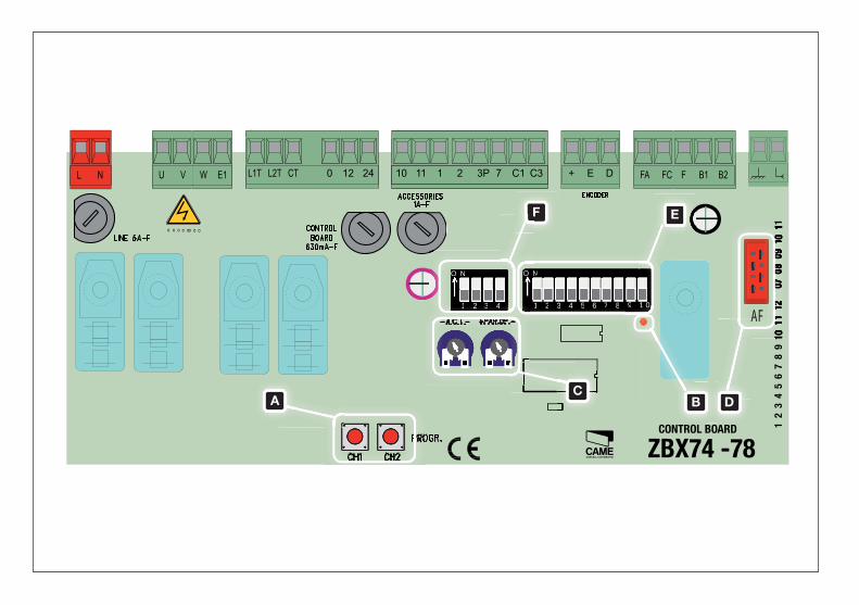
Collegamenti elettrici
IT
L-N Alimentazione 230V (a.c.) 50/60 Hz
10-11 Alimentazione accessori 24V (a.c.)
W-E1 Lampeggiatore di segnalazione (portata contatto: 230V -
25W max.)
W-E1 Lampada ciclo (portata contatto: 230V - 60W max.)
Posizionare di 1 e 6 in ON
11-FC Spia cancello aperto (Portata contatto: 24V - 3W max.)
11-FA Spia cancello chiuso (Portata contatto: 24V - 3W max.)
2-C1 Contatto (N.C.) di riapertura durante la chiusura
2-C3 Contatto (N.C.) di stop parziale
U-V-W Motoriduttore 230V a.c.
+-E-D Encoder 230V (E=nero, D=rosso)
1-2 Pulsante di stop (contatto N.C.)
2-3P Selettore a chiave e/o pulsante di apertura parziale (N.O.)
2-7 Selettore a chiave e/o pulsante per comandi (N.O.)
B1-B2 Uscita eventuale secondo canale del ricevitore radio (N.O.).
Portata contatto: 5A-24V (d.c.).
Collegamento antenna
FA-F finecorsa apre (contatto N.C.)
FC-F finecorsa chiude (contatto N.C.)
-Collegare il cavo RG58 dell’antenna agli appositi morsetti.
-Innestare la scheda di radiofrequenza sulla scheda elettronica D DOPO AVER TOLTO LA TENSIONE (o scollegato le batterie).
N.B.: La scheda elettronica riconosce la scheda di radiofrequenza solo quando viene alimentata.
Attivazione del comando radio
Memorizzazione
CH1 = Canale per comandi diretti a una funzione della scheda del motoriduttore (comando “solo apre” / “apre-chiude-inversione” oppure
“apre-stop-chiude-stop”, a seconda della selezione effettuata sui dip-switch 2 e 3).
CH2 = Canale per comando diretto ad un dispositivo accessorio o per il comando di due motori abbinati, collegato su B1-B2.
-Tenere premuto il tasto “CH1” A sulla scheda elettronica. Il led lampeggia. B
-Premere il tasto del trasmettitore da memorizzare. Il led rimarrà acceso a segnalare l’avvenuta memorizzazione.
-Ripetere la procedura per il tasto “CH2” associandolo con un altro tasto del trasmettitore.
ITA
LIA
NO
I dati e le informazioni indicate in questo manuale sono da ritenersi suscettibili di modifica in qualsiasi momento e senza obbligo di preavviso da parte di CAME cancelli automatici s.p.a.
Pag.
4
- C
odic
e m
anua
le: 3
19
LR2
23
19
LR2
2 v
er. 3
07
/201
3 ©
CA
ME
canc
elli
auto
mat
ici s
.p.a
.
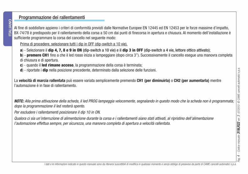
Programmazione dei rallentamenti
NOTE: Alla prima attivazione della scheda, il led PROG lampeggia velocemente, segnalando in questo modo che la scheda non è programmata;
dopo la programmazione il led resterà spento.
Per escludere i rallentamenti posizionare il dip 10 in ON.
Qualora ci sia un’interruzione di alimentazione durante la corsa e i rallentamenti siano stati attivati, al ripristino dell’alimentazione
l’automazione effettua sempre, per sicurezza, una manovra completa di apertura a velocità rallentata.
La velocità di marcia rallentata può essere variata semplicemente premendo CH1 (per diminuirla) o CH2 (per aumentarla) mentre
l’automazione è in fase di rallentamento.
Al fi ne di soddisfare appieno i criteri di conformità previsti dalle Normative Europee EN 12445 ed EN 12453 per le forze massime d’impatto,
BX-74/78 è predisposto per il rallentamento della corsa a 50 cm dai punti di fi necorsa in apertura e chiusura. Al momento dell’installazione è
suffi ciente programmare la corsa del cancello nel seguente modo:
Prima di procedere, selezionare tutti i dip in OFF (dip-switch a 10 vie).
a) - Selezionare il dip 4, 7, 8 e 9 in ON (dip-switch a 10 vie) e il dip 3 in OFF (dip-switch a 4 vie, lettore ottico attivato);
b) - premere CH1 fi no a che il led rosso inizia a lampeggiare (dopo circa 3”). Successivamente il cancello esegue una manovra completa
di chiusura e di apertura.
c) - quando il led rimane acceso, la programmazione della corsa è terminata;
d) - riportate i dip nella posizione precedente, determinato dalla selezione delle funzioni.
ITA
LIA
NO
Pag.
5
- C
odic
e m
anua
le: 3
19
LR2
23
19
LR2
2 v
er. 3
07
/201
3 ©
CA
ME
canc
elli
auto
mat
ici s
.p.a
.
I dati e le informazioni indicate in questo manuale sono da ritenersi suscettibili di modifica in qualsiasi momento e senza obbligo di preavviso da parte di CAME cancelli automatici s.p.a.
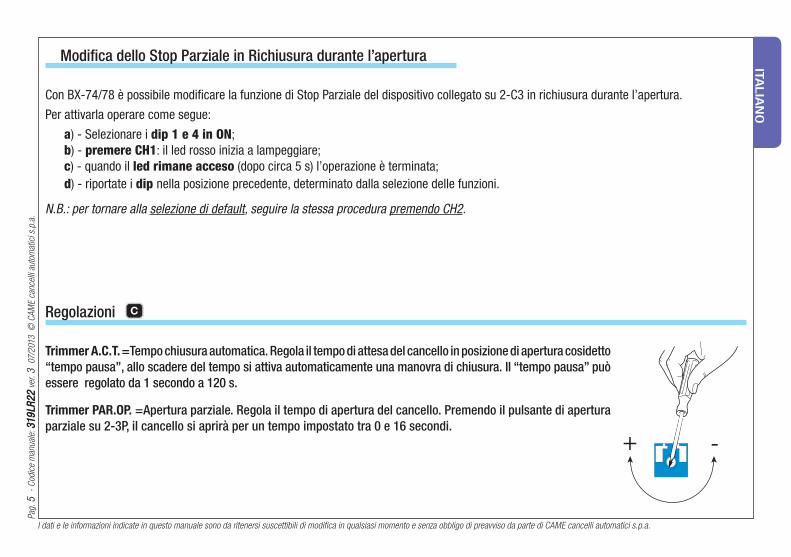
Regolazioni C
Modifica dello Stop Parziale in Richiusura durante l’apertura
Trimmer A.C.T. =Tempo chiusura automatica. Regola il tempo di attesa del cancello in posizione di apertura cosidetto
“tempo pausa”, allo scadere del tempo si attiva automaticamente una manovra di chiusura. Il “tempo pausa” può
essere regolato da 1 secondo a 120 s.
Trimmer PAR.OP. = Apertura parziale. Regola il tempo di apertura del cancello. Premendo il pulsante di apertura
parziale su 2-3P, il cancello si aprirà per un tempo impostato tra 0 e 16 secondi.
Con BX-74/78 è possibile modifi care la funzione di Stop Parziale del dispositivo collegato su 2-C3 in richiusura durante l’apertura.
Per attivarla operare come segue:
a) - Selezionare i dip 1 e 4 in ON;
b) - premere CH1: il led rosso inizia a lampeggiare;
c) - quando il led rimane acceso (dopo circa 5 s) l’operazione è terminata;
d) - riportate i dip nella posizione precedente, determinato dalla selezione delle funzioni.
N.B.: per tornare alla selezione di default, seguire la stessa procedura premendo CH2.
ITA
LIA
NO
I dati e le informazioni indicate in questo manuale sono da ritenersi suscettibili di modifica in qualsiasi momento e senza obbligo di preavviso da parte di CAME cancelli automatici s.p.a.
Pag.
6
- C
odic
e m
anua
le: 3
19
LR2
23
19
LR2
2 v
er. 3
07
/201
3 ©
CA
ME
canc
elli
auto
mat
ici s
.p.a
.
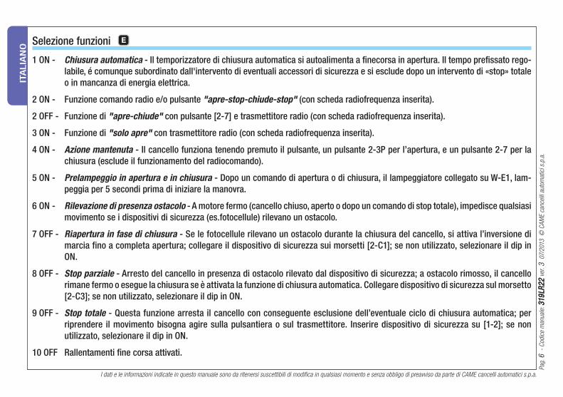
Selezione funzioni E
1 ON - Chiusura automatica - Il temporizzatore di chiusura automatica si autoalimenta a fi necorsa in apertura. Il tempo prefi ssato rego-
labile, é comunque subordinato dall'intervento di eventuali accessori di sicurezza e si esclude dopo un intervento di «stop» totale
o in mancanza di energia elettrica.
2 ON - Funzione comando radio e/o pulsante "apre-stop-chiude-stop" (con scheda radiofrequenza inserita).
2 OFF - Funzione di "apre-chiude" con pulsante [2-7] e trasmettitore radio (con scheda radiofrequenza inserita).
3 ON - Funzione di "solo apre" con trasmettitore radio (con scheda radiofrequenza inserita).
4 ON - Azione mantenuta - Il cancello funziona tenendo premuto il pulsante, un pulsante 2-3P per l’apertura, e un pulsante 2-7 per la
chiusura (esclude il funzionamento del radiocomando).
5 ON - Prelampeggio in apertura e in chiusura - Dopo un comando di apertura o di chiusura, il lampeggiatore collegato su W-E1, lam-
peggia per 5 secondi prima di iniziare la manovra.
6 ON - Rilevazione di presenza ostacolo - A motore fermo (cancello chiuso, aperto o dopo un comando di stop totale), impedisce qualsiasi
movimento se i dispositivi di sicurezza (es.fotocellule) rilevano un ostacolo.
7 OFF - Riapertura in fase di chiusura - Se le fotocellule rilevano un ostacolo durante la chiusura del cancello, si attiva l’inversione di
marcia fino a completa apertura; collegare il dispositivo di sicurezza sui morsetti [2-C1]; se non utilizzato, selezionare il dip in
ON.
8 OFF - Stop parziale - Arresto del cancello in presenza di ostacolo rilevato dal dispositivo di sicurezza; a ostacolo rimosso, il cancello
rimane fermo o esegue la chiusura se è attivata la funzione di chiusura automatica. Collegare dispositivo di sicurezza sul morsetto
[2-C3]; se non utilizzato, selezionare il dip in ON.
9 OFF - Stop totale - Questa funzione arresta il cancello con conseguente esclusione dell’eventuale ciclo di chiusura automatica; per
riprendere il movimento bisogna agire sulla pulsantiera o sul trasmettitore. Inserire dispositivo di sicurezza su [1-2]; se non
utilizzato, selezionare il dip in ON.
10 OFF Rallentamenti fi ne corsa attivati.
ITA
LIA
NO
Pag.
7
- C
odic
e m
anua
le: 3
19
LR2
23
19
LR2
2 v
er. 3
07
/201
3 ©
CA
ME
canc
elli
auto
mat
ici s
.p.a
.
I dati e le informazioni indicate in questo manuale sono da ritenersi suscettibili di modifica in qualsiasi momento e senza obbligo di preavviso da parte di CAME cancelli automatici s.p.a.
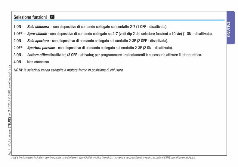
1 ON - Solo chiusura - con dispositivo di comando collegato sul contatto 2-7 (1 OFF - disattivata).
1 OFF - Apre-chiude - con dispositivo di comando collegato su 2-7 (vedi dip 2 del selettore funzioni a 10 vie) (1 ON - disattivata).
2 ON - Sola apertura - con dispositivo di comando collegato sul contatto 2-3P (2 OFF - disattivata).
2 OFF - Apertura parziale - con dispositivo di comando collegato sul contatto 2-3P (2 ON - disattivata).
3 ON - Lettore ottico disattivato; (3 OFF - attivato); per programmare i rallentamenti è necessario attivare il lettore ottico.
4 ON - Non connesso.
NOTA: le selezioni vanno eseguite a motore fermo in posizione di chiusura.
Selezione funzioni F

ITA
LIA
NO
I dati e le informazioni indicate in questo manuale sono da ritenersi suscettibili di modifica in qualsiasi momento e senza obbligo di preavviso da parte di CAME cancelli automatici s.p.a.
Pag.
8
- C
odic
e m
anua
le: 3
19
LR2
23
19
LR2
2 v
er. 3
07
/201
3 ©
CA
ME
canc
elli
auto
mat
ici s
.p.a
.
I nostri prodotti sono realizzati con materiali diversi. La maggior parte di essi (alluminio, plastica, ferro, cavi elettrici) è assimilabile ai rifi uti
solidi e urbani. Possono essere riciclati attraverso la raccolta e lo smaltimento differenziato nei centri autorizzati.
Altri componenti (schede elettroniche, batterie dei transmettitori etc.) possono invece contenere sostanze inquinanti.
Vanno quindi rimossi e consegnati a ditte autorizzate al recupero e allo smaltimento degli stessi.
Dismissione e smaltimento
Codice di riferimento per richiedere una copia conforme all’originale: DDF L IT Z001b

The data and information reported in this installation manual are susceptible to change at any time and without obligation on CAME cancelli automatici s.p.a. to notify users.
Pag.
9
- M
anua
l cod
e: 3
19
LR2
23
19
LR2
2 v
er. 3
07
/201
3 ©
CA
ME
canc
elli
auto
mat
ici s
.p.a
.E
NG
LIS
H
Electrical connections
EN
L-N Power supply 230V (a.c.) 50/60 Hz
10-11 Terminals for powering 24V (a.c.) accessories
W-E1 Flashing light (socket rating: 230V - 25W max.)
W-E1 Cycle lamp: (contact rating: 230V – 60W max.)
Set DIP 1 and 6 switch to ON.
11-FC Open gate indicator-light (socket rating: 24V - 3W max.)
11-FA Close gate indicator-light (socket rating: 24V - 3W max.)
2-C1 Re-open during closing (N.C.) socket
2-C3 Partial stop” (N.C.) socket
U-V-W 230V (d.c.) motor
+-E-D Encoder 230V (E=black, D=red)
1-2 Stop button (N.C. socket)
2-3P Keyswitch and/or partial opening button (N.O.)
2-7 Keyswitch and/or commands button (N.O.)
B1-B2 Possible output of the radio receiver’s second channel
(N.O.). Socket rating: 5A-24V (d.c.).
Connection of antenna
FA-F finecorsa apre (contatto N.C.)
FC-F finecorsa chiude (contatto N.C.)
-Connect the antenna’s RG58 cable to the apposite terminals.
-Lock the radiofrequency card into the electronic card D AFTER CUTTING OFF THE POWER SUPPLY (or after disconnecting the batte-
ries).
N.B.: the electronic card only recognises the radiofrequency card when the power is on.
Activating the remote control
Memorisation
CH1 = Channel for direct command to a function of the the gearmotor’s card, (“open only / “open-close-invert” or “open-stop-close-stop”
command, depending on the choice made on DIP switches 2 and 3).
CH2 = Channel for direct command to an auxiliary device or for the control of two paired motors, connected to B1-B2.
-Keep the “CH1” A button on the electronic card pressed. The LED fl ashes. B
-Press the transmitter button you wish to memorise. The LED will stay on to show memorisation has been successful.
-Repeat the procedures for the “CH2” button associating this to another button on the transmitter.
The data and information reported in this installation manual are susceptible to change at any time and without obligation on CAME cancelli automatici s.p.a. to notify users.
Pag.
10
10
-
Man
ual c
ode:
31
9LR
22
31
9LR
22
ver
. 3
07
/201
3 ©
CA
ME
canc
elli
auto
mat
ici s
.p.a
.
EN
GLIS
H
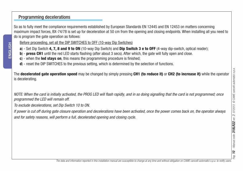
Programming decelerations
The decelerated gate operation speed may be changed by simply pressing CH1 (to reduce it) or CH2 (to increase it) while the operator
is decelerating.
NOTE: When the card is initially activated, the PROG LED will fl ash rapidly, and in so doing signalling that the card is not programmed; once
programmed the LED will remain off.
To exclude decelerations, set Dip Switch 10 to ON.
If power is cut off during gate closure operation and decelerations have been activated, once the power comes back on, the operator always
and for safety reasons, will perform a full, decelerated opening and closing cycle.
So as to fully meet the compliance requirements established by European Standards EN 12445 and EN 12453 on matters concerning
maximum impact forces, BX-74/78 is set up for deceleration at 50 cm from the opening and closing endpoints. When installing all you need to
do is program the gate operation as follows:
Before proceeding, set all the DIP SWITCHES to OFF (10-way Dip Switches)
a) - Set Dip Switch 4, 7, 8 and 9 to ON (10-way Dip Switch) and Dip Switch 3 e to OFF (4-way dip-switch, optical reader);
b) - press CH1 until the red LED starts fl ashing (after about 3 secs). After which, the gate will fully open and close.
c) - when the led stays on, this means the programming procedure is fi nished;
d) - reset the DIP SWITCHES to the previous setting, which is determined by the selection of functions.

The data and information reported in this installation manual are susceptible to change at any time and without obligation on CAME cancelli automatici s.p.a. to notify users.
Pag.
1111
-
Man
ual c
ode:
31
9LR
22
31
9LR
22
ver
. 3
07
/201
3 ©
CA
ME
canc
elli
auto
mat
ici s
.p.a
.E
NG
LIS
H
Adjustment Trimmer C
Trimmer A.C.T. =Sets the waiting time while open. Once this time has elapsed, closing automatically takes
place. The waiting time may be set from 1 to 120 seconds.
Trimmer PAR.OP. = Sets the gate’s partial opening. By pushing the partial opening button connected at 2-3P,
the gate will open for a set time between 0 and 16 seconds.
Modifying the Re-closing Partial Stop during opening
With BX-74/78 you can change the function of the Re-closing Partial Stop during opening, which is connected on 2-C3.
To activate it, do the following:
a) - Set Dip Switch 1 and 4 on ON;
b) - press CH1: the red LED will start to fl ash;
c) - when the LED stays lit up (after about 5 secs) this means that the procedure is fi nished;
d) - reset the DIP SWITCHES to the previous setting, which is determined by the selection of functions.
N.B.: to go back to the default selection, follow the same procedure but press CH2.

The data and information reported in this installation manual are susceptible to change at any time and without obligation on CAME cancelli automatici s.p.a. to notify users.
Pag.
12
12
-
Man
ual c
ode:
31
9LR
22
31
9LR
22
ver
. 3
07
/201
3 ©
CA
ME
canc
elli
auto
mat
ici s
.p.a
.
EN
GLIS
H
Function selector E
1 ON - Automatic Closing - The automatic closing timer activates at the end of the opening gate run. The pre-set time is adjustable,
and is in any case conditioned by the activation of any safety devices, and does not activate after a total safety “stop” or during
a blackout.
2 ON - "Open-stop-close-stop" function with [2-7] button and radio transmitter (fi tted with inserted radiofrequency card).
2 OFF - "Open-close" function with [2-7] button and radio transmitter ((fi tted with inserted radiofrequency card).
3 ON - "Open only" function with radio transmitter ((fi tted with inserted radiofrequency card).
4 ON - Maintained action - The gate works by keeping button pressed (one 2-3P opening button , and one 2-7 closing button).
5 ON - Pre-Opening and closing fl asher - Following and opening and closing command, the fl asher connected to [W-E1], fl ashes for 5
seconds before motion begins.
6 ON - Obstacle detected - When motor is stopped (gate closed or after a total stop command) it prevents any movement if safety devices,
such as photocells, detect any obstacles.
7 OFF - Opening during closing - If the photocells detect an obstacle during gate’s closing, gate motion is inverted until fully opened;
connect the safety device to terminals [2-C1]; if unused, set DIP switch to ON.
8 OFF - Partial stop - Gate stop when obstacle is detected by the safety device; once obstacle is removed, the gate remains still or closes
if automatic closing is activated. Connect the safety device to terminal [2-C3]; if unused, set the DIP switch to ON.
9 OFF - Total stop - This function stops the gate and then excludes any automatic closing cycle; to set in motion again, use either the
keypad or transmitter. Insert the safety device in [1-2]; If unused, set DIP switch to ON.
10 OFF Limit switch slowing activated.

The data and information reported in this installation manual are susceptible to change at any time and without obligation on CAME cancelli automatici s.p.a. to notify users.
Pag.
13
13
-
Man
ual c
ode:
31
9LR
22
31
9LR
22
ver
. 3
07
/201
3 ©
CA
ME
canc
elli
auto
mat
ici s
.p.a
.E
NG
LIS
H
1 ON - Closing only – with command device connected on contact 2-7 (1 OFF – deactivated)
1 OFF - Open-close – with command device connected on 2-7 (see 10-way Dip Switch 2 of the function selector) (1 ON – deactivated).
2 ON - Only opening – with command device connected on contact 2-3P (2 OFF – deactivated).
2 OFF - Partial opening – with command device connected on contact 2-3P (2 ON – deactivated).
3 ON - Optical reader deactivated; (3 OFF –activated); to program deceleration you need to activated the optical reader.
4 ON - disconnected
NOTE: make selections when motor is stopped and in the closed position.
Function selector F

The data and information reported in this installation manual are susceptible to change at any time and without obligation on CAME cancelli automatici s.p.a. to notify users.
Pag.
1414
-
Man
ual c
ode:
31
9LR
22
31
9LR
22
ver
. 3
07
/201
3 ©
CA
ME
canc
elli
auto
mat
ici s
.p.a
.
EN
GLIS
H
Disposal
This product, including the packaging, is made up of several types of materials that can be recycled.
Investigate the recycling or disposal systems of the product, complying with prevailing local legislation.
Some electronic components may contain polluting substances. Do not litter.

Pag.
15
15
-
Cod
e m
anue
l: 3
19
LR2
23
19
LR2
2 v
er. 3
07
/201
3 ©
CA
ME
canc
elli
auto
mat
ici s
.p.a
.
Les données et les indications fournies dans ce manuel d’installation peuvent subir des modifications à tout moment sans avis préalable de la part de CAME cancelli automatici s.p.a.
FR
AN
ÇA
IS
Branchements électriques
FR
L-N Alimentation 230V (a.c.) 50/60 Hz
10-11 Alimentation des accessoires 24V (a.c.)
W-E1 Clignotant de signalisation (portée contact : 230V - 25W
max.)
W-E1 Lampe cycle (230V - 60W max.) sélectionnez le dip 1 et 6 sur
ON.
11-FC Voyant portail ouverte (Portée contact : 24V - 3 W max.)
11-FA Voyant portail fermée (Portée contact : 24V - 3 W max.)
2-C1 Contact (N.C.) de “réouverture pendant la fermeture”
2-C3 Contact (N.C.) de stop partiel
U-V-W Moteur 230V a.c.
+-E-D Encoder 230V (E=noir, D=rouge)
1-2 Boutons de stop (N.C.)
2-3P Sélecteur à clé et/ou bouton d’ouverture partielle (N.O.)
2-7 Sélecteur à clé et/ou bouton pour les commandes (N.O.)
B1-B2 Sortie éventuelle du deuxième canal du récepteur radio (N.O.).
Portée contact : 5A-24V (d.c.)
Branchement antenne
FA-F finecorsa apre (contatto N.C.)
FC-F finecorsa chiude (contatto N.C.)
-Branchez le câble RG58 de l’antenne aux borniers correpondants.
-Branchez la carte de radiofréquence sur la carte électronique D APRÈS AVOIR COUPÉ LE COURANT (ou débranchez les batteries).
N.B. : La carte électronique reconnaît la carte de radiofréquence seulement quand elle est alimentée.
Mise en service de l’émetteur
Mise en mémoire
CH1 = Canal pour commandes directes à une fonction de la carte du motoréducteur (commande “ouvre seulement” / “ouvre-ferme-inver-
sion” ou bien “ouvre-stop-ferme-stop”, selon la sélection effectuée sur les dip-switch 2 et 3).
CH2 = Canal pour commande directe à un dispositif accessoire ou pour la commande de deux moteurs accouplés, branché sur B1-B2.
-Appuyez sans relâcher la touche “CH1” A sur la carte électronique. La led clignote. B
-Appuyez sur la touche de l’émetteur à mémoriser. La led restera allumée pour confi rmer que la mise en mémoire a été effectuée.
-Répétez l’opération pour la touche “CH2” en l’associant à une autre touche de l’émetteur.
Les données et les indications fournies dans ce manuel d’installation peuvent subir des modifications à tout moment sans avis préalable de la part de CAME cancelli automatici s.p.a.
Pag.
16
16
-
Cod
e m
anue
l: 3
19
LR2
23
19
LR2
2 v
er. 3
07
/201
3 ©
CA
ME
canc
elli
auto
mat
ici s
.p.a
.
FR
AN
ÇA
IS
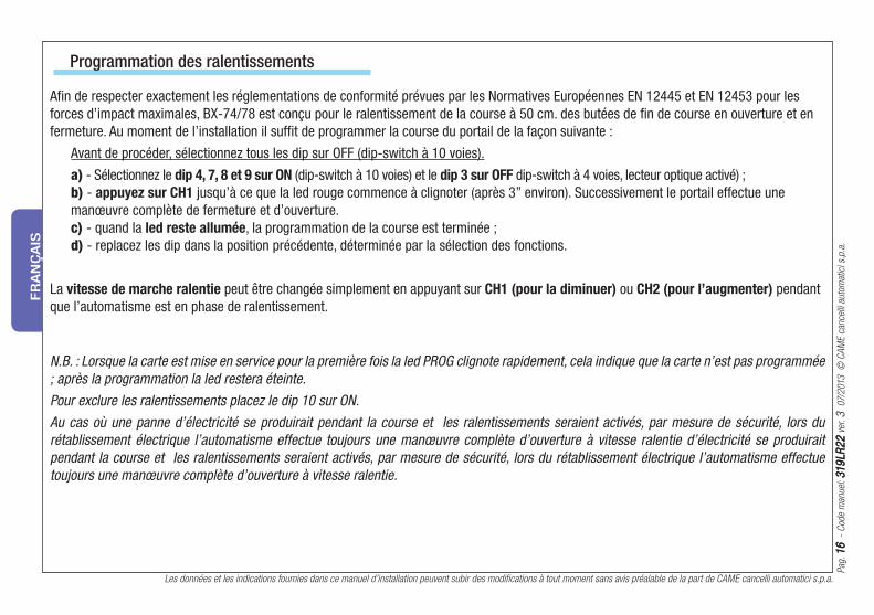
Programmation des ralentissements
N.B. : Lorsque la carte est mise en service pour la première fois la led PROG clignote rapidement, cela indique que la carte n’est pas programmée
; après la programmation la led restera éteinte.
Pour exclure les ralentissements placez le dip 10 sur ON.
Au cas où une panne d’électricité se produirait pendant la course et les ralentissements seraient activés, par mesure de sécurité, lors du
rétablissement électrique l’automatisme effectue toujours une manœuvre complète d’ouverture à vitesse ralentie d’électricité se produirait
pendant la course et les ralentissements seraient activés, par mesure de sécurité, lors du rétablissement électrique l’automatisme effectue
toujours une manœuvre complète d’ouverture à vitesse ralentie.
La vitesse de marche ralentie peut être changée simplement en appuyant sur CH1 (pour la diminuer) ou CH2 (pour l’augmenter) pendant
que l’automatisme est en phase de ralentissement.
Afi n de respecter exactement les réglementations de conformité prévues par les Normatives Européennes EN 12445 et EN 12453 pour les
forces d’impact maximales, BX-74/78 est conçu pour le ralentissement de la course à 50 cm. des butées de fi n de course en ouverture et en
fermeture. Au moment de l’installation il suffi t de programmer la course du portail de la façon suivante :
Avant de procéder, sélectionnez tous les dip sur OFF (dip-switch à 10 voies).
a) - Sélectionnez le dip 4, 7, 8 et 9 sur ON (dip-switch à 10 voies) et le dip 3 sur OFF dip-switch à 4 voies, lecteur optique activé) ;
b) - appuyez sur CH1 jusqu’à ce que la led rouge commence à clignoter (après 3” environ). Successivement le portail effectue une
manœuvre complète de fermeture et d’ouverture.
c) - quand la led reste allumée, la programmation de la course est terminée ;
d) - replacez les dip dans la position précédente, déterminée par la sélection des fonctions.

Pag.
1717
-
Cod
e m
anue
l: 3
19
LR2
23
19
LR2
2 v
er. 3
07
/201
3 ©
CA
ME
canc
elli
auto
mat
ici s
.p.a
.
Les données et les indications fournies dans ce manuel d’installation peuvent subir des modifications à tout moment sans avis préalable de la part de CAME cancelli automatici s.p.a.
FR
AN
ÇA
IS
Réglages des compensateurs C
Trimmer A.C.T. =Il règle la durée de l’attente en position d’ouverture. Lorsque ce délai est écoulé, la manœuvre
de fermeture s’effectue automatiquement. La durée du temps d’attente peut être fixée de 1 à 120 secondes.
Trimmer PAR.OP. = Il règle l’ouverture partielle du portail. En appuyant sur le bouton d’ouverture partielle
connecté sur 2-3P, le porttail s’ouvre pendant un temps réglé de 0 à 16 secondes.
Modification du Stop Partiel en fermeture pendant l’ouverture
Avec BX-74/78 il est possible de modifi er la fonction de Stop Partiel du dispositif raccordé sur 2-C3 en Réenclenchement de la fermeture
pendant l’ouverture.
Pour l’activer procédez de la façon suivante :
a) - Sélectionnez les dip 1 et 4 sur ON ;
b) - appuyez sur CH1 : la led rouge commence à clignoter ;c) - quand la led reste allumée (environ 5 s après) l’opération est terminée ;
d) - replacez les dip dans la position précédente, déterminée par la sélection des fonctions.
N.B. : pour revenir à la sélection par défaut, effectuez la même procédure en appuyant sur CH2.
Les données et les indications fournies dans ce manuel d’installation peuvent subir des modifications à tout moment sans avis préalable de la part de CAME cancelli automatici s.p.a.
Pag.
18
18
-
Cod
e m
anue
l: 3
19
LR2
23
19
LR2
2 v
er. 3
07
/201
3 ©
CA
ME
canc
elli
auto
mat
ici s
.p.a
.
FR
AN
ÇA
IS
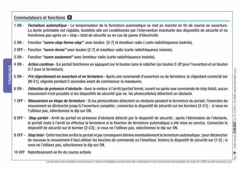
Commutateurs et fonctions E
1 ON - Fermeture automatique - Le temporisateur de la fermeture automatique se met en marche en fin de course en ouverture.
La durée préétablie est réglable, toutefois elle est conditionnée par l’intervention éventuelle des dispositifs de sécurité et ne
fonctionne pas après un « stop » total de sécurité ou en cas de panne d’électricité.
2 ON - Fonction ”ouvre-stop-ferme-stop” avec bouton [2-7] et émetteur radio ( carte radiofréquence insérée).
2 OFF - Fonction ”ouvre-ferme” avec bouton [2-7] et émetteur radio (carte radiofréquence insérée).
3 ON - Fonction “ouvre seulement” avec émetteur radio (carte radiofréquence insérée).
4 ON - Action continue - ILe portail fonctionne en appuyant sur le bouton sans le relâcher (un bouton 2-3P pour l’ouverture et un bouton
2-7 pour la fermeture).
5 ON - Pré clignotement en ouverture et en fermeture - Après une commande d’ouverture ou de fermeture, le clignotant connecté sur
[W-E1], clignote pendant 5 secondes avant de commencer la manœuvre.
6 ON - Détection de présence d’obstacle - Avec le moteur à l’arrêt (portail fermé, ouvert ou après une commande de stop total), aucun
mouvement n’est possible si les dispositifs de sécurité (par ex. les photocellules) détectent un obstacle.
7 OFF - Réouverture en étape de fermeture - Si les photocellules détectent un obstacle pendant la fermeture du portail, l’inversion du
mouvement se déclenche jusqu’à l’ouverture complète ; connectez le dispositif de sécurité sur les borniers [2-C1] ; si vous ne
l’utilisez pas, sélectionnez le dip sur ON.
8 OFF - Stop partiel - Arrêt du portail en présence d’obstacle détecté par le dispositif de sécurité ; après l’élimination de l’obstacle,
le portail reste à l’arrêt ou effectue la fermeture si la fonction de fermeture automatique a été mise en service. Connectez le
dispositif de sécurité sur le bornier [2-C3] ; si vous ne l’utilisez pas, sélectionnez le dip sur ON.
9 OFF - Stop total - Cette fonction arrête le portail et par conséquent élimine éventuellement la fermeture automatique ; pour déclencher
de nouveau le mouvement il faut utiliser les touches de commande ou l’émetteur. Insérez le dispositif de sécurité sur [1-2] ; si
vous ne l’utilisez pas, sélectionnez le dip sur ON.
10 OFF Ralentissement en fi n de course activée
Pag.
19
19
-
Cod
e m
anue
l: 3
19
LR2
23
19
LR2
2 v
er. 3
07
/201
3 ©
CA
ME
canc
elli
auto
mat
ici s
.p.a
.
Les données et les indications fournies dans ce manuel d’installation peuvent subir des modifications à tout moment sans avis préalable de la part de CAME cancelli automatici s.p.a.
FR
AN
ÇA
IS
Commutateurs et fonctions E
1 ON - Fermeture seulement - avec le dispositif de commande raccordé sur le contact 2-7 ( 1 OFF – Désactivée).
1 OFF - Ouvre-ferme - avec le dispositif de commande raccordé sur 2-7 (voir dip 2 du sélecteur de fonctions à 10 voies) (1 ON – désactivée)
2 ON - Ouverture seulement - avec le dispositif de commande raccordé sur le contact 2-3P (2 OFF – désactivée).
2 OFF - Ouverture partielle - avec le dispositif de commande raccordé sur le contact 2-3P (2 ON – désactivée).
3 ON - Lecteur optique désactivé ; (3 OFF – activée) ; pour programmer les ralentissements il faut activer le lecteur optique.
4 ON - Débranché.
N.B. : les sélections doivent être faites avec le moteur à l’arrêt en position de fermeture.

Les données et les indications fournies dans ce manuel d’installation peuvent subir des modifications à tout moment sans avis préalable de la part de CAME cancelli automatici s.p.a.
Pag.
20
20
-
Cod
e m
anue
l: 3
19
LR2
23
19
LR2
2 v
er. 3
07
/201
3 ©
CA
ME
canc
elli
auto
mat
ici s
.p.a
.
FR
AN
ÇA
IS
Cet appareil, y compris l’emballage, est constitué de plusieurs types de matériaux pouvant être recyclés.
S’informer sur les systèmes de recyclage ou d’élimination de l’appareil en se conformant aux lois locales en vigueur.
Certains composants électroniques pourraient contenir des substances polluantes, ne pas les jeter n’importe où.
Recyclage et élimination

Sei
te 2
12
1
- H
andb
uch-
Cod
e: 3
19
LR2
23
19
LR2
2 v
er. 3
07
/201
3 ©
CA
ME
canc
elli
auto
mat
ici s
.p.a
.
Sämtliche in der Installationsanleitung aufgeführten Daten und Informationen können jederzeit und ohne Vorankündigung von CAME cancelli automatici s.p.a verändert werden.
DE
UTS
CH
Elektrischer anschluss
DE
L-N Anschluss 230V (a.c.) 50/60 Hz
10-11 Elektrischen Anschluss der Zubehörteile 24V (a.c.)
W-E1 Warnleuchte (Anschlussleistung: 230V – 25W max.)
W-E1 Betriebszyklus-Anzeigeleuchte (230V - 60W max.)
DIP 1 ON – DIP 6 ON
11-FC Kontrollleuchte Tor offen (Anschlussleistung: 24-3W max.)
11-FA Kontrollleuchte Tor geschlossen (Anschluss.: 24-3W max.)
2-C1 Kontakt (N.C.) «Reversierung während des Zulaufs»
2-C3 Kontakt (N.C.) «Teilstopp»
U-V-W Motor 230V a.c.
+-E-D Encoder 230V (E=Schwarz, D=Rot)
1-2 Stopp-Taster (N.C.)
2-3P Schlüsseltaster bzw. Teilaufl auf-Taster (N.O.)
2-7 Schlüsseltaster bzw. Befehlstaster (N.O.)
B1-B2 Eventueller Ausgang des zweiten Kanals des Funkempfän-
gers (N.O.)
Antennenanschluss
FA-F finecorsa apre (contatto N.C.)
FC-F finecorsa chiude (contatto N.C.)
-Kabel RG58 der Antenne an die dafür vorgesehenen Klemmen anschließen.
-Funksteckmodul auf der Steuerplatine aufstecken D , NACH UNTERBRECHUNG DER STROMZUFUHR (bzw. nach Entfernung der Batterien).
N.B.: Die Steckkarte erkennt das Funksteckmodul nur wenn sie mit Strom gespeist wird.
Aktivierung des Senders
Speichem
CH1 = Kanal für Befehle an eine Funktion der Steuerung des Getriebemotors (Befehl „nur auf“ / „auf-zu-reversiere“ bzw. „auf-stopp-zu-
stopp“ je nach Wahl auf den Dip-Switches 2 und 3).
CH2 = Kanal für Befehle an ein auf B1-B2 angeschlossenes Zusatzgerät.
1) Den Taster “CH1” A auf der Steuerplatine gedrückt halten. Das Led blinkt. B
2) Den zu speichernden Taster auf dem Sender drücken. Das Led bleibt an und zeigt so die erfolgte Speicherung an.
3) Den in Punkt 1 und 2 beschriebenen Vorgang für den Taster “CH2” wiederholen und diesen mit einem anderen Taster auf der Fernbedienung
kombinieren.

Sämtliche in der Installationsanleitung aufgeführten Daten und Informationen können jederzeit und ohne Vorankündigung von CAME cancelli automatici s.p.a verändert werden.
Sei
te 2
22
2
- H
andb
uch-
Cod
e: 3
19
LR2
23
19
LR2
2 v
er. 3
07
/201
3 ©
CA
ME
canc
elli
auto
mat
ici s
.p.a
.
DE
UTS
CH
Einstellung der Soft-Stops
ANMERKUNGEN: Beim ersten Einschalten der Steuerung blinkt die Leuchtdiode PROG schnell. So wird angezeigt, dass die Steuerung noch
nicht programmiert wurde; nach erfolgter Programmierung bleibt die Diode aus.
Um die Soft-Stops auszuschließen, Dip 10 auf ON stellen.
Sollte bei eingeschalteten Soft-Stops der Strom während des Torlaufs ausfallen, führt der Antrieb, nach Ende des Stromausfalls, zur Sicherheit
einen kompletten Aufl auf bei verlangsamter Geschwindigkeit durch.
Die Geschwindigkeit des verlangsamten Torlaufs kann, während des verlangsamten Torlaufs, durch Druck auf CH1 (langsamer) oder CH2
(schneller) verändert werden.
Um die von den Euronormen EN 12445 und EN 12453 für Schubkräfte vorgegebenen Konformitätskriterien einzuhalten, ist bei BX-74/78 50
cm vor den Endlaufpunkten im Auf- und Zulauf die Verlangsamung des Torlaufs vorgesehen. Bei Installierung genügt es, den Torlauf, wie im
folgenden beschrieben, einzustellen:
Vor der Einstellung, alle Dips auf OFF stellen (10-Wege Dip-Schalter).
a) - Dip 4, 7, 8 und 9 auf ON (10-Wege-Dip-Schalter) und Dip 3 auf OFF stellen; (4-Wege-Dip-Schalter, optisches Lesegerät
eingeschaltet);
b) - CH1 drücken, bis die rote Leuchtdiode blinkt (nach ca. 3“). Danach führt das Tor einen vollständigen Zyklus – Auf- und Zulauf – aus.
c) - wenn die Leuchtdiode an bleibt, ist die Einstellung des Torlaufs beendet;
d) - Die Dips wieder auf ihre vorherige von der Funktionswahl.
Sei
te 2
32
3
- H
andb
uch-
Cod
e: 3
19
LR2
23
19
LR2
2 v
er. 3
07
/201
3 ©
CA
ME
canc
elli
auto
mat
ici s
.p.a
.
Sämtliche in der Installationsanleitung aufgeführten Daten und Informationen können jederzeit und ohne Vorankündigung von CAME cancelli automatici s.p.a verändert werden.
DE
UTS
CH
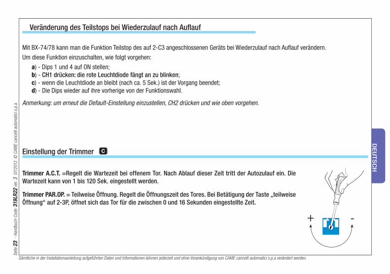
Einstellung der Trimmer C
Trimmer A.C.T. =Regelt die Wartezeit bei offenem Tor. Nach Ablauf dieser Zeit tritt der Autozulauf ein. Die
Wartezeit kann von 1 bis 120 Sek. eingestellt werden.
Trimmer PAR.OP. = Teilweise Öffnung. Regelt die Öffnungszeit des Tores. Bei Betätigung der Taste „teilweise
Öffnung“ auf 2-3P, öffnet sich das Tor für die zwischen 0 und 16 Sekunden eingestellte Zeit.
Veränderung des Teilstops bei Wiederzulauf nach Auflauf
Mit BX-74/78 kann man die Funktion Teilstop des auf 2-C3 angeschlossenen Geräts bei Wiederzulauf nach Aufl auf verändern.
Um diese Funktion einzuschalten, wie folgt vorgehen:
a) - Dips 1 und 4 auf ON stellen;
b) - CH1 drücken: die rote Leuchtdiode fängt an zu blinken;
c) - wenn die Leuchtdiode an bleibt (nach ca. 5 Sek.) ist der Vorgang beendet;
d) - Die Dips wieder auf ihre vorherige von der Funktionswahl.
Anmerkung: um erneut die Default-Einstellung einzustellen, CH2 drücken und wie oben vorgehen.
Sämtliche in der Installationsanleitung aufgeführten Daten und Informationen können jederzeit und ohne Vorankündigung von CAME cancelli automatici s.p.a verändert werden.
Sei
te 2
42
4
- H
andb
uch-
Cod
e: 3
19
LR2
23
19
LR2
2 v
er. 3
07
/201
3 ©
CA
ME
canc
elli
auto
mat
ici s
.p.a
.
DE
UTS
CH
Funktionswahl E
1 ON - Autozulauf - Der Zeitmesser des Autozulaufs aktiviert sich bei Endlauf im Auflauf. Die vorgegebene Zeit ist einstellbar und hängt
in jedem Fall von den Sicherheitseinrichtungen ab. Autozulauf wird nach Notstopp und bei Stromausfall nicht aktiviert.
2 ON - Funktion "auf-stopp-zu-stopp" über Befehlstaster [2-7] und Funkbefehl (bei eingestecktem Funkmodul).
2 OFF - Funktion "auf-zu" über Befehlstaster [2-7] und Funkbefehl (bei eingestecktem Funkmodul).
3 ON - Funktion "nur Aufl auf" über Funkbefehl (bei eingestecktem Funkmodul).
4 ON - Totmannbetrieb - Das Tor funktioniert durch ständigen Druck eines Tasters (ein Taster 2-3P für Aufl auf und ein Taster 2-7 für den
Zulauf).
5 ON - orblinken bei Auf- und Zulauf - Nach Auf- bzw. Zu-Befehl blinkt die über [W-E1] verbundene Warnleuchte 5 Sek. lang auf, bevor
die Torbewegung einsetzt.
6 ON - Hinderniserfassung - Bei stehendem Motor (Tor zu, auf oder nach Notstopp) wird jegliche Torbewegung unterdrückt, wenn die
Sicherheitseinrichtungen (z.B. Lichtschranken) ein Hindernis erfassen.
7 OFF - Wiederaufl auf bei Zulauf - Bei Hinderniserfassung durch die Lichtschranken während des Zulaufs wird die Torbewegung bis zum
völligen Auflauf des Tores reversiert; Sicherheitseinrichtungen mit Klemmen [2-C1] verbinden. Bei Nichtverwendung Dip auf ON
stellen.
8 OFF - Teilstopp - Unterbrechung der Torbewegung nach Hinderniserfassung durch die Sicherheitseinrichtungen; nach Entfernung
des Hindernisses bleibt das Tor stehen bzw., wenn die Funktion Autozulauf aktiviert wurde, wird der Autozulauf bewirkt.
Sicherheitseinrichtung mit Klemmen [2-C3] verbinden. Bei Nichtverwendung Dip auf ON stellen.
9 OFF - Notstopp - Diese Funktion unterbricht die Torbewegung und schließt den Autozulauf aus; über Befehlstaster bzw. Funkbefehl
wird die Torbewegung wieder aufgenommen. Sicherheitseinrichtung mit [1-2] verbinden; Bei Nichtverwendung den Dip auf ON
stellen.
10 OFF Abbremsen am Endanschlag.

Sei
te 2
52
5
- H
andb
uch-
Cod
e: 3
19
LR2
23
19
LR2
2 v
er. 3
07
/201
3 ©
CA
ME
canc
elli
auto
mat
ici s
.p.a
.
Sämtliche in der Installationsanleitung aufgeführten Daten und Informationen können jederzeit und ohne Vorankündigung von CAME cancelli automatici s.p.a verändert werden.
DE
UTS
CH
Funktionswahl F
1 ON - Nur Zulauf - Befehlsgerät auf Kontakt 2-7 angeschlossen (1 OFF - nicht eingeschaltet).
1 OFF - Auf-und Zulauf - Befehlsgerät auf 2-7 angeschlossen (siehe Dip 2 des zehn-Wege-Nummerntasters) (1 ON - nicht eingeschaltet).
2 ON - Nur Aufl auf - Befehlsgerät auf Kontakt 2-3P angeschlossen (2 OFF - nicht eingeschaltet).
2 OFF - Teilaufl auf - Befehlsgerät auf Kontakt 2-3P angeschlossen (2 ON - nicht eingeschaltet).
3 ON - optisches Lesegerät nicht eingeschaltet; (3 OFF - eingeschaltet); Zur Einstellung der Soft-Stops muss das optische Lesegerät eingeschaltet werden.
4 ON - nicht angeschlossen
ANMERKUNG: Die Einstellungen werden bei geschlossenem Tor und abgeschaltetem Motor durchgeführt.
Sämtliche in der Installationsanleitung aufgeführten Daten und Informationen können jederzeit und ohne Vorankündigung von CAME cancelli automatici s.p.a verändert werden.
Sei
te 2
62
6
- H
andb
uch-
Cod
e: 3
19
LR2
23
19
LR2
2 v
er. 3
07
/201
3 ©
CA
ME
canc
elli
auto
mat
ici s
.p.a
.
DE
UTS
CH
Dieses Produkt einschließlich Verpackungen besteht aus verschiedenen wiederverwertbaren Materialien.
Informieren Sie sich unter Berücksichtigung der örtlich geltenden Rechtsvorschriften über die Recycling- und Entsorgungssysteme des Produkts.
Einige elektronische Bauteile könnte verschmutzende Substanzen enthalten – nicht in der Umwelt zerstreuen.
Entsorgung
Pag.
27
27
-
Cod
igo
man
ual:
31
9LR
22
31
9LR
22
ver
. 3
07
/201
3 ©
CA
ME
canc
elli
auto
mat
ici s
.p.a
.
Los datos y las informaciones indicadas en este manual de instalación podrían modificarse en cualquier momento y sin obligación de aviso previo por parte de la firma CAME cancelli automatici s.p.a.
ES
PA
ÑO
L
Conexiones eléctricas
ES
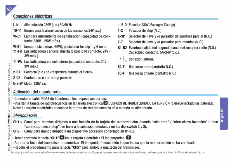
-Conectar el cable RG58 de la antena a los respectivos bornes.
-Insertar la tarjeta de radiofrecuencia en la tarjeta electrónica D DESPUÉS DE HABER QUITADO LA TENSIÓN (o desconectado las baterías).
Nota: La tarjeta electrónica reconoce la tarjeta de radiofrecuencia sólo cuando es alimentada.
Activación del mando radio
Memorización
CH1 = Canal para mandos dirigidos a una función de la tarjeta del motorreductor (mando “sólo abre” / “abre-cierra-inversión” o bien
“abre-stop-cierra-stop”, en base a la selección efectuada en los dip-switch 2 y 3).
CH2 = Canal para mando dirigido a un dispositivo accesorio conectado en B1-B2.
-Tener apretada la tecla “CH1” A en la tarjeta electrónica.El led parpadea. B
-Apretar la tecla del transmisor a memorizar: El led quedará encendido lo que indica que la memorización se ha verifi cado.
-Repetir el procedimiento para la tecla “CH2” asociándolo a una tecla del transmisor.
L-N Alimentación 230V (a.c.) 50/60 Hz
10-11 Bornes para la alimentación de los accesorios 24V (a.c.)
W-E1 Lámpara intermitente de señalización (capacidad de con-
tacto: 230V - 25W máx.)
W-E1 làmpara ciclo (max. 60W), posicionar los dip 1 y 6 en on
11-FC Luz indicadora cancela abierta (capacidad contacto: 24V -
3W máx.)
11-FA Luz indicadora cancela cierre (capacidad contacto: 24V -
3W máx.)
2-C1 Contacto (n.c.) de «reapertura durante el cierre»
2-C3 Contacto (n.c.) de «stop parcial»
U-V-W Motor 230V a.c.
+-E-D Encoder 230V (E=negro, D=rojo)
1-2 Pulsador de stop (N.C.)
2-3P Selector de llave y /o pulsador de apertura parcial (N.O.)
2-7 Selector de llave y /o pulsador para mandos (N.O.)
B1-B2 Eventual salida del segundo canal del receptor radio (N.O.)
Capacidad contacto: 5A-24V (c.c.).
Conexión antena
FA-F finecorsa apre (contatto N.C.)
FC-F finecorsa chiude (contatto N.C.)

Los datos y las informaciones indicadas en este manual de instalación podrían modificarse en cualquier momento y sin obligación de aviso previo por parte de la firma CAME cancelli automatici s.p.a.
Pag.
28
28
-
Cod
igo
man
ual:
31
9LR
22
31
9LR
22
ver
. 3
07
/201
3 ©
CA
ME
canc
elli
auto
mat
ici s
.p.a
.
ES
PA
ÑO
L
Programación de los ralentís
NOTAS: Durante la primera activación de la tarjeta, el led PROG parpadea rápidamente, lo que indica que la tarjeta no está programada;
después de la programación, el led quedará apagado.
Para excluir los ralentís, ubicar el dip 10 en ON.
En caso de interrupción de la alimentación durante la carrera y si los ralentís han sido activados, en el momento de restablecimiento de la
misma, la automatización efectúa siempre una maniobra completa de apertura con velocidad ralentizada por motivos de seguridad.
La velocidad de marcha ralentizada puede variarse apretando simplemente CH1 (para disminuirla) o CH2 (para aumentarla) mientras la
automatización está en fase de ralentí.
Con el objetivo de satisfacer completamente los criterios de conformidad previstos por las Normativas Europeas EN 12445 y EN 12453
respecto a las fuerzas de impacto, BX-74/78 está predispuesto para el ralentí de la carrera a 50 cm. de los puntos de fi nal de carrera en
apertura y cierre. Durante la instalación es sufi ciente programar la carrera de la puerta de la siguiente manera:
Antes de operar, seleccionar todos los dip en OFF (dip-switch de 10 vías).
a) - Seleccionar el dip 4, 7, 8 y 9 en ON (dip-switch de 10 vías) y el dip 3 en OFF (dip-switch de 4 vías, lector óptico activado);
b) - apretar CH1 hasta que el led rojo comienza a parpadear (después de 3” aprox.). Después la puerta efectúa una maniobra completa de
cierre y de apertura.
c) - cuando el led queda encendido, la programación de la carrera se concluye;
d) - llevar los dip a la posición anterior, determinada por la selección de las funciones.

Pag.
29
29
-
Cod
igo
man
ual:
31
9LR
22
31
9LR
22
ver
. 3
07
/201
3 ©
CA
ME
canc
elli
auto
mat
ici s
.p.a
.
Los datos y las informaciones indicadas en este manual de instalación podrían modificarse en cualquier momento y sin obligación de aviso previo por parte de la firma CAME cancelli automatici s.p.a.
ES
PA
ÑO
L
Regulaciones Trimmer C
Modificación del Stop Parcial en fase de Recierre durante la apertura
Trimmer T.C.A. = Regula el tiempo de espera en posición de apertura. Transcurrido dicho tiempo, se efectúa
automáticamente una maniobra de cierre. El tiempo de espera puede regularse desde 1 a 150 segundos.
Trimmer AP.PARZ. = Regula la apertura parcial de la cancela. Apretando el pulsador de apertura parcial co-
nectado en 2-3P, la puerta se abrirá durante un tiempo configurado entre 0 y 16 segundos.
Con BX-74/78 es posible modifi car la función de Stop Parcial del dispositivo conectado en 2-C3 en recierre durante la apertura.
Para activarla, efectuar las siguientes operaciones:
a) - Seleccionar los dip 1 y 4 en ON;
b) - apretar CH1: el led rojo comienza a parpadear;c) - cuando el led queda encendido (después de aprox. 5 s.) la operación está concluida;
d) - llevar los dip a la posición anterior, determinada por la selección de las funciones.
NOTA: para volver a la selección por defecto, efectuar el mismo procedimiento apretando CH2.
Los datos y las informaciones indicadas en este manual de instalación podrían modificarse en cualquier momento y sin obligación de aviso previo por parte de la firma CAME cancelli automatici s.p.a.
Pag.
30
30
-
Cod
igo
man
ual:
31
9LR
22
31
9LR
22
ver
. 3
07
/201
3 ©
CA
ME
canc
elli
auto
mat
ici s
.p.a
.
ES
PA
ÑO
L
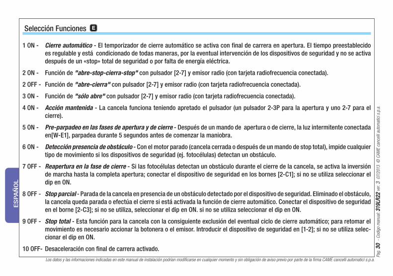
Selección Funciones E
1 ON - Cierre automático - El temporizador de cierre automático se activa con final de carrera en apertura. El tiempo preestablecido
es regulable y está condicionado de todas maneras, por la eventual intervención de los dispositivos de seguridad y no se activa
después de un «stop» total de seguridad o por falta de energía eléctrica.
2 ON - Función de "abre-stop-cierra-stop" con pulsador [2-7] y emisor radio (con tarjeta radiofrecuencia conectada).
2 OFF - Función de "abre-cierra" con pulsador [2-7] y emisor radio (con tarjeta radiofrecuencia conectada).
3 ON - Función de "sólo abre" con pulsador [2-7] y emisor radio (con tarjeta radiofrecuencia conectada).
4 ON - Acción mantenida - La cancela funciona teniendo apretado el pulsador (un pulsador 2-3P para la apertura y uno 2-7 para el
cierre).
5 ON - Pre-parpadeo en las fases de apertura y de cierre - Después de un mando de apertura o de cierre, la luz intermitente conectada
en[W-E1], parpadea durante 5 segundos antes de comenzar la maniobra.
6 ON - Detección presencia de obstáculo - Con el motor parado (cancela cerrada o después de un mando de stop total), impide cualquier
tipo de movimiento si los dispositivos de seguridad (ej. fotocélulas) detectan un obstáculo.
7 OFF - Reapertura en la fase de cierre - Si las fotocélulas detectan un obstáculo durante el cierre de la cancela, se activa la inversión
de marcha hasta la completa apertura; conectar el dispositivo de seguridad en los bornes [2-C1]; si no se utiliza seleccionar el
dip en ON.
8 OFF - Stop parcial - Parada de la cancela en presencia de un obstáculo detectado por el dispositivo de seguridad. Eliminado el obstáculo,
la cancela queda parada o efectúa el cierre si está activada la función de cierre automático. Conectar el dispositivo de seguridad
en el borne [2-C3]; si no se utiliza, seleccionar el dip en ON. si no se utiliza seleccionar el dip en ON.
9 OFF - Stop total - Esta función para la cancela con la consiguiente exclusión del eventual ciclo de cierre automático; para retomar el
movimiento es necesario accionar la botonera o el emisor. Introducir el dispositivo de seguridad en [1-2]; si no se utiliza selec-
cionar el dip en ON.
10 OFF- Desaceleración con fi nal de carrera activado.

Pag.
31
31
-
Cod
igo
man
ual:
31
9LR
22
31
9LR
22
ver
. 3
07
/201
3 ©
CA
ME
canc
elli
auto
mat
ici s
.p.a
.
Los datos y las informaciones indicadas en este manual de instalación podrían modificarse en cualquier momento y sin obligación de aviso previo por parte de la firma CAME cancelli automatici s.p.a.
ES
PA
ÑO
L
1 ON - Sólo cierre -con dispositivo de mando conectado en el contacto 2-7 (1 OFF - desactivada).
1 OFF – Abre-cierra - con dispositivo de mando conectado en el contacto 2-7 (véase dip del selector funciones de 10 vías) (1 ON - desactivada).
2 ON - Sólo apertura - con dispositivo de 2 ON - Sólo apertura - con dispositivo de mando conectado en el contacto 2-3P (2 OFF - desactivada).
2 OFF - Apertura parcial - con dispositivo de mando conectado en el contacto 2-3P (2 ON - desactivada).
3 ON - Lector óptico desactivado; (3 OFF - activado); para programar los ralentís, es necesario activar el lector óptico.
4 ON - No conectado.
NOTA: las selecciones se deben efectuar con el motor parado en posición de cierre.
Selección Funciones

Los datos y las informaciones indicadas en este manual de instalación podrían modificarse en cualquier momento y sin obligación de aviso previo por parte de la firma CAME cancelli automatici s.p.a.
Pag.
32
32
-
Cod
igo
man
ual:
31
9LR
22
31
9LR
22
ver
. 3
07
/201
3 ©
CA
ME
canc
elli
auto
mat
ici s
.p.a
.
ES
PA
ÑO
L
Este producto, incluido el embalaje, está hecho con diferentes tipos de materiales que pueden reciclarse.
Infórmese sobre los sistemas de reciclaje o eliminación del producto, respetando las normas locales vigentes.
Algunos componentes electrónicos podrían contener substancias contaminantes; no los abandone en el medio ambiente.
Desguase

Pag.
33
33
-
Han
dlei
ding
num
mer
: 3
19
LR2
23
19
LR2
2 v
er. 3
07
/201
3 ©
CA
ME
canc
elli
auto
mat
ici s
.p.a
.
De gegevens en informatie in deze handleiding voor de installatie zijn op elk ogenblik vatbaar voor wijziging zonder verplichting tot waarschuwing vooraf door Came Cancelli Automatici S.p.A.
NE
DE
RLA
ND
S
Elektrische aansluitingen
NL
L-N Aansluitstroom 230V (a.c.) 50/60 Hz
10-11 Stroomaansluitklemmen voor de accessoires 24V (a.c.)
W-E1 Flitslamp (vermogen van het contact: 230V - 25W max.
W-E1 Cycluslamp (vermogen van het contact: 230V - 60W max.) Dip 1ON - dip 6 ON
11-FC Lampje “hek open” (Vermogen van contact: 24V - 3W max.)
11-FA Lampje “hek sluiten” (Vermogen van contact: 24V - 3W max.)
2-C1 Contact (N.C.) voor «weer openen tijdens sluiten»
2-C3 Contact (N.C.) voor «stop halverwege»
U-V-W Motor 230V a.c.
+-E-D Encoder 230V (E=zwart, D=rood)
1-2 Stopknop (contatto N.C.)
2-3P Vergrendelbare schakelaar met sleutel en/of knop om de halve poort te openen (N.O.)
2-7 Vergrendelbare schakelaar met sleutel en/of knop voor be-dieningen (N.O.)
B1-B2 Eventuele uitgang van het tweede kanaal van de radio-ontvanger (N.O.).
Antenneaansluiting
FA-F finecorsa apre (contatto N.C.)
FC-F finecorsa chiude (contatto N.C.)
-Sluit de kabel RG58 van de antenne aan op de bijbehorende klemmen.
-Koppel de frequentiekaart aan de elektronische printkaart D NADAT U EERST DE SPANNIGN HEBT UITGEZET (of de batterijen hebt
losgemaakt).
Opm.: De elektronische printkaart herkent de radiokaart alleen als de spanning wordt ingeschakeld.
De radiobediening inschakelen
Opslaan
CH1 = Kanaal voor directe commando’s van een functie op de printkaart van de aandrijving (commando “alleen openen” / “open-sluit-
omkeren” of “open-stop-sluit-stop”, afhankelijk van de manier waarop de dip-switches 2 en 3 zijn gezet).
CH2 = Kanaal voor commando’s gericht op een accessoires of voor commando van twee gekoppelde motoren, aangesloten op B1-B2.
-Houd de toets “CH1” A op de printkaart ingedrukt.Het lampje knippert. B
-Druk de toets van de zender in die u wenst te confi gureren. Het lampje zal blijven branden om te signaleren dat de zender geconfi gureerd is.
-Herhaal de procedure met de toets “CH2” om deze toe te wijzen aan een andere toets van de zender.

De gegevens en informatie in deze handleiding voor de installatie zijn op elk ogenblik vatbaar voor wijziging zonder verplichting tot waarschuwing vooraf door Came Cancelli Automatici S.p.A.
Pag.
34
34
-
Han
dlei
ding
num
mer
: 3
19
LR2
23
19
LR2
2 v
er. 3
07
/201
3 ©
CA
ME
canc
elli
auto
mat
ici s
.p.a
.
NE
DE
RLA
ND
S
Vertragingen programmeren
OPMERKING: Als de printkaart voor het eerst wordt gebruikt, knippert het lampje PROG snel. Dit signaleert dat de kaart nog niet is
geprogrammeerd. Als de kaart geprogrammeerd is, blijft dit lampje uit.
Om het hek niet te laten vertragen, zet u de dip 10 op ON.
Als de stroom uitvalt tijdens de baan en er zijn vertragingen geprogrammeerd, zal de aandrijving altijd voor de veiligheid het hek volledig
openen en sluiten met een lagere snelheid.
U kunt de snelheid van de vertraagde baan wijzigen door CH1 in te drukken (lager) of CH2 (hoger) terwijl het hek aan het vertragen is.
Om te voldoen aan de criteria van overeenstemming van de Europese normen EN 12445 en EN 12453 inzake de maximale sluitkracht,
is BX-74/78 uitgerust met een vertraging van de baan op 50 cm van de eindaanslagen open en gesloten hek. Tijdens de installatie
programmeert u de baan van het hek op de volgende manier:
In de eerste plaats zet u alle dips op OFF (dip switches met 10 uitgangen).
a) - Zet de dip 4, 7, 8, en 9 op ON (dip-switch met 10 uitgangen) en de dip 3 op OFF (dip-switch met 4 uitgangen, optische lezer aan);
b) - druk op CH1 totdat het rode lampje begint te knipperen (na ong. 3sec). Het hek zal één keer volledig openen en sluiten
c) - zodra het lampje aan blijft, is de baan van het hek geprogrammeerd;
d) - Zet de dips weer in hun vorige stand (die hoort bij de gekozen functie).
Pag.
35
35
-
Han
dlei
ding
num
mer
: 3
19
LR2
23
19
LR2
2 v
er. 3
07
/201
3 ©
CA
ME
canc
elli
auto
mat
ici s
.p.a
.
De gegevens en informatie in deze handleiding voor de installatie zijn op elk ogenblik vatbaar voor wijziging zonder verplichting tot waarschuwing vooraf door Came Cancelli Automatici S.p.A.
NE
DE
RLA
ND
S
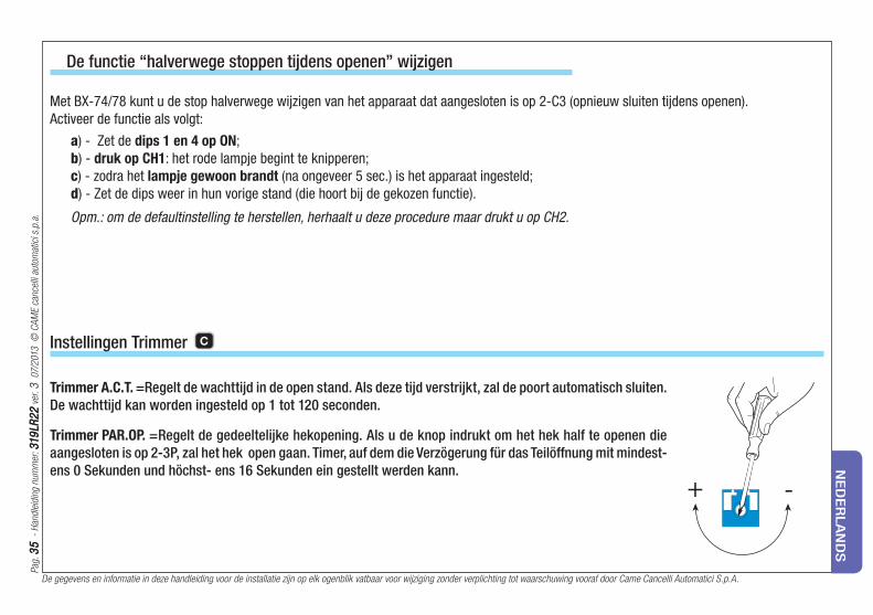
Instellingen Trimmer C
Met BX-74/78 kunt u de stop halverwege wijzigen van het apparaat dat aangesloten is op 2-C3 (opnieuw sluiten tijdens openen).
Activeer de functie als volgt:
a) - Zet de dips 1 en 4 op ON;
b) - druk op CH1: het rode lampje begint te knipperen;
c) - zodra het lampje gewoon brandt (na ongeveer 5 sec.) is het apparaat ingesteld;
d) - Zet de dips weer in hun vorige stand (die hoort bij de gekozen functie).
Opm.: om de defaultinstelling te herstellen, herhaalt u deze procedure maar drukt u op CH2.
De functie “halverwege stoppen tijdens openen” wijzigen
Trimmer A.C.T. =Regelt de wachttijd in de open stand. Als deze tijd verstrijkt, zal de poort automatisch sluiten.
De wachttijd kan worden ingesteld op 1 tot 120 seconden.
Trimmer PAR.OP. = Regelt de gedeeltelijke hekopening. Als u de knop indrukt om het hek half te openen die
aangesloten is op 2-3P, zal het hek open gaan. Timer, auf dem die Verzögerung für das Teilöffnung mit mindest-
ens 0 Sekunden und höchst- ens 16 Sekunden ein gestellt werden kann.

De gegevens en informatie in deze handleiding voor de installatie zijn op elk ogenblik vatbaar voor wijziging zonder verplichting tot waarschuwing vooraf door Came Cancelli Automatici S.p.A.
Pag.
36
36
-
Han
dlei
ding
num
mer
: 3
19
LR2
23
19
LR2
2 v
er. 3
07
/201
3 ©
CA
ME
canc
elli
auto
mat
ici s
.p.a
.
NE
DE
RLA
ND
S
Selectie functies E
1 ON - Automatisch sluiten - De timer voor het automatisch sluiten, begint te werken als het hek op de eindaanslag in de open stand
komt. De geprogrammeerde tijd kan worden ingesteld en hangt in elk geval af van het in werking treden van de beveiligingen.
De timer start niet na een totale «stop» noodstop of als er geen stroom is.
2 ON - Functie “openen-stop-sluiten-stop”met knop (2-7) en radiozender (met gemonteerde radiofrequentiekaart).
2 OFF - Functie “openen-sluiten” met knop (2-7) en radiozender (met gemonteerde radiofrequentiekaart).
3 ON - Functie “alleen openen” met knop (2-7) en radiozender (met gemonteerde radiofrequentiekaart).
4 ON - Ingeduwde bedieningsknop - Het hek werkt als de knop ingedrukt wordt gehouden (een knop 2-3P voor het openen en een knop
2-7 voor het sluiten).
5 ON - Eerste waarschuwing van het knipperlicht tijdens het openen en het sluiten - Als een commando tot openen of sluiten wordt
gegeven, zal het knipperlicht dat is aangesloten op het contact [W-E1] 5 seconden knipperen voordat de beweging begint.
6 ON - Obstakel waarnemen - Met stilstaande motor (hek gesloten, open of na een commando voor totale stilstand), belet dit elke
beweging als de beveiligingen (bijvoorbeeld de fotocellen) een obstakel waarnemen.
7 OFF - Weer openen tijdens sluiten - SAls de fotocellen een obstakel waarnemen tijdens het sluiten, wordt de beweging omgekeerd
totdat het hek weer helemaal open is; sluit de beveiliging aan op de klemmen [2-C1]; indien niet gebuikt, zet u de dip op ON.
8 OFF - Gedeeltelijke stilstand - Het hek stopt als de beveiliging een obstakel signaleert. Als dit obstakel er niet meer is, blijft het hek
blijft stilstaan of sluit als de automatische sluiting is ingesteld. Sluit de beveiliging aan op de klem [2-C3]; indien niet gebruikt,
zet u de dip op ON.
9 OFF - Totale stilstand - Met deze functie stopt het hek helemaal, waardoor ook de eventuele automatische sluitingen worden uitgeschakeld;
om de beweging te hernemen, dient u de knoppen of de zender te gebruiken. Zet het ijbehorende veiligheidsmechanisme op [1-2];
indien niet gebruikt zet u de dip op ON.
10 OFF Vertraging aan eindeloop.
Pag.
37
37
-
Han
dlei
ding
num
mer
: 3
19
LR2
23
19
LR2
2 v
er. 3
07
/201
3 ©
CA
ME
canc
elli
auto
mat
ici s
.p.a
.
De gegevens en informatie in deze handleiding voor de installatie zijn op elk ogenblik vatbaar voor wijziging zonder verplichting tot waarschuwing vooraf door Came Cancelli Automatici S.p.A.
NE
DE
RLA
ND
S
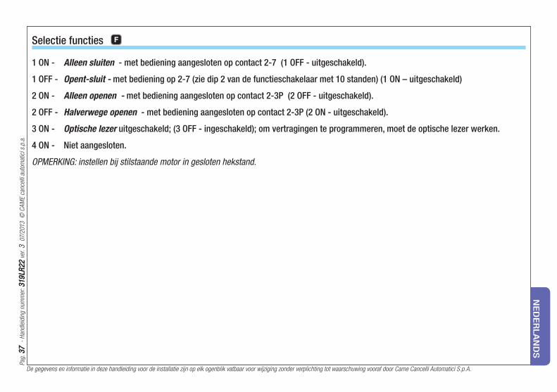
1 ON - Alleen sluiten - met bediening aangesloten op contact 2-7 (1 OFF - uitgeschakeld).
1 OFF - Opent-sluit - met bediening op 2-7 (zie dip 2 van de functieschakelaar met 10 standen) (1 ON – uitgeschakeld)
2 ON - Alleen openen - met bediening aangesloten op contact 2-3P (2 OFF - uitgeschakeld).
2 OFF - Halverwege openen - met bediening aangesloten op contact 2-3P (2 ON - uitgeschakeld).
3 ON - Optische lezer uitgeschakeld; (3 OFF - ingeschakeld); om vertragingen te programmeren, moet de optische lezer werken.
4 ON - Niet aangesloten.
OPMERKING: instellen bij stilstaande motor in gesloten hekstand.
Selectie functies F

De gegevens en informatie in deze handleiding voor de installatie zijn op elk ogenblik vatbaar voor wijziging zonder verplichting tot waarschuwing vooraf door Came Cancelli Automatici S.p.A.
Pag.
38
38
-
Han
dlei
ding
num
mer
: 3
19
LR2
23
19
LR2
2 v
er. 3
07
/201
3 ©
CA
ME
canc
elli
auto
mat
ici s
.p.a
.
NE
DE
RLA
ND
S
Afvalverwerking
Dit product, inclusief de verpakking, werd vervaardigd uit verschillende materialen die gerecycleerd kunnen worden.
Informeer in uw land over de recyclagemethoden of afvalverwerking van het product en volg de plaatselijke normen die van kracht zijn.
Elektronische onderdelen kunnen vervuilende stoffen bevatten: laat ze niet in het milieu achter.


31
9LR
22
31
9LR
22
ver
. 3
07
/201
3 ©
CA
ME
canc
elli
auto
mat
ici s
.p.a
.
IT • Per ogni ulteriore informazione su azienda, prodotti e assistenza nella vostra lingua:EN • For any further information on company, products and assistance in your language:
FR • Pour toute autre information sur la société, les produits et l’assistance dans votre langue :DE • Weitere Infos über Unternehmen, Produkte und Kundendienst bei:
ES • Por cualquier información sobre la empresa, los productos y asistencia en su idioma:NL • Voor meer informatie over het bedrijf, de producten en hulp in uw eigen taal:
PT • Para toda e qualquer informação acerca da empresa, de produtos e assistência técnica, em sua língua:PL • Wszystkie inne informacje dotyczące fi rmy, produktów oraz usług i pomocy technicznej w Waszym języku znajdują się na stronie:
RU • Для получения дополнительной информации о компании, продукции и сервисной поддержке на вашем языке:HU • A vállalatra, termékeire és a műszaki szervizre vonatkozó minden további információért az Ön nyelvén:
HR • Za sve dodatne informacije o poduzeću, proizvodima i tehničkoj podršci:UK • Для отримання будь-якої іншої інформації про компанію, продукцію та технічну підтримку:
CAME Cancelli Automatici S.p.a.CAME Cancelli Automatici S.p.a.Via Martiri Della Libertà, 15
31030 Dosson Di Casier Dosson Di Casier (Tv) (+39) 0422 4940 (+39) 0422 4941
Assistenza Tecnica/Numero Verde 800 295830Assistenza Tecnica/Numero Verde 800 295830
www. came.comwww. came.com


