SCENARIO OF FRACTURE DEVELOPMENT IN BUCKET WHEEL...
16
85 SCENARIO OF FRACTURE DEVELOPMENT IN BUCKET WHEEL EXCAVATOR Darko Daničić 1 , Stojan Sedmak 2 , Ivo Blačić 3 1 Kolubara metal, Lazarevac, Serbia 2 University of Belgrade, Faculty of Technology and Metallurgy, Belgrade, Serbia 3 Military Technical Institute, Belgrade, Serbia e-mail [email protected] Abstract: Continued service of BWE in the severe working conditions may result in machine failure. In case of important structural elements it might lead to a large- scale breakdown. The allocation of structurally significant elements is of vital importance for the lifecycle of BWE, starting from design and construction, through operation and maintenance. The example of recent failure of one BWE caused by complex fracture, consisting of fatigue and final fast fracture is considered. Possible scenario indicated that fracture started from a small element due to defects introduced by poor quality of welded joints which significance in structure was underestimated in given operating condition and applied loading. Key words: welding joint; stress distribution; structural integrity; maintenance
Transcript of SCENARIO OF FRACTURE DEVELOPMENT IN BUCKET WHEEL...
85
SCENARIO OF FRACTURE DEVELOPMENT IN BUCKET WHEEL EXCAVATOR
Darko Daničić1, Stojan Sedmak2, Ivo Blačić3
1Kolubara metal, Lazarevac, Serbia 2University of Belgrade, Faculty of Technology and Metallurgy, Belgrade, Serbia 3Military Technical Institute, Belgrade, Serbia
e-mail [email protected]
Abstract: Continued service of BWE in the severe working conditions may result in machine failure. In case of important structural elements it might lead to a large-scale breakdown. The allocation of structurally significant elements is of vital importance for the lifecycle of BWE, starting from design and construction, through operation and maintenance. The example of recent failure of one BWE caused by complex fracture, consisting of fatigue and final fast fracture is considered. Possible scenario indicated that fracture started from a small element due to defects introduced by poor quality of welded joints which significance in structure was underestimated in given operating condition and applied loading. Key words: welding joint; stress distribution; structural integrity; maintenance
D. Daničić, S. Sedmak, I. Blačić
1. INTRODUCTION
In-service behavior of bucket wheel excavator (BWE) and other equipment operating on surface mines (bucket chain excavators, spreaders, belt wagons, stackers), aimed to supply electrical power plants by coal, depends on the design, capacity, manufacturing quality, applied loading and typical mining conditions (stability of mining area, strength of overburden mass, allowable soil loading). BWE development and application include design and manufacturing, acceptance for service after performed requested testing, operation, in-service inspection and maintenance. Structural integrity can be endangered in each of these steps, and this requires the decision to continue the operation or undertake the repair of damaged components. In spite of strictly obeyed prescribed rules and sequences, premature damages and failures of surface mine equipment occur in service, causing significant costs. Such failures are experienced also in opencasts surface coal mines in Serbia, and one of them is selected for a detailed consideration. In addition to direct costs, the losses due to downtimes caused by failure disturb electricity production, and for that they are important.
Performed failure analysis revealed that wheel with buckets and boom are most critical parts, requiring in some cases to improve the design /1-5/. One important aspect of excavator design is fatigue and fracture behavior of welded steel structures /6-8/. Welded joints, due to imperfections caused by manufacturing and heterogeneous microstructure (parent metal - PM, weld metal - WM, heat-affected-zone – HAZ) are most critical parts regarding crack initiation and growth, requiring special attention when exposed to variable loading and fatigue, as it is the case on open surface mines.
The service problems of equipment operating on surface mines attracted the attention and in many papers they had been considered /9-12/.
2. FAILURE OF A BUCKET WHEEL EXCAVATOR
To avoid unexpected failures of bucket wheel excavators (BWE) and save their structural integrity in service, necessary care during operational life, monitoring and diagnostics of all vital elements of supporting structure, sometimes also repairing and redesign, are required.
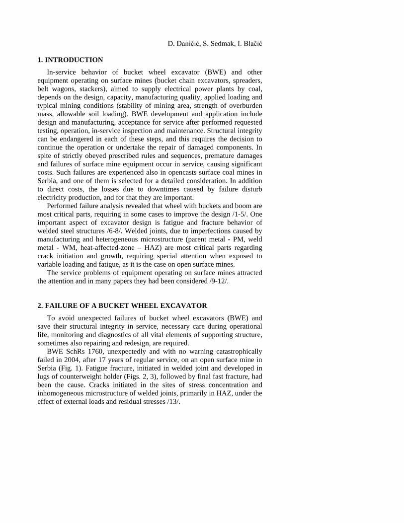
BWE SchRs 1760, unexpectedly and with no warning catastrophically failed in 2004, after 17 years of regular service, on an open surface mine in Serbia (Fig. 1). Fatigue fracture, initiated in welded joint and developed in lugs of counterweight holder (Figs. 2, 3), followed by final fast fracture, had been the cause. Cracks initiated in the sites of stress concentration and inhomogeneous microstructure of welded joints, primarily in HAZ, under the effect of external loads and residual stresses /13/.
87
Figure 1. Collapse of bucket wheel excavator SRs 1760
The fracture surfaces of left lug, pos. 68 (Fig. 3.a) and right lug, pos. 62
(Fig. 3.b) are substantially different. Right lug fractured in brittle manner, due to an overloading. Brute fracture in left lug took place when the loaded cross section area was significantly reduced after extended fatigue cracks on both sides of welded rib (Fig. 3). Flat fatigue crack growth in pos. 68 had been interrupted by stable crack growths, with visible shear lips.
Figure 2. Fracture of two lugs on counterweight holder
a.
b.
Figure 3.a. Lug (pos. 68) fracture (fatigue, stable crack growth and brute fracture) b. Brittle fracture of lug (pos. 62), indicating single initiation point from both sites
pos. 68
pos. 62

D. Daničić, S. Sedmak, I. Blačić
2.1. Analysis of applied load and stress distribution The loading acting on the bucket wheel is stochastic. It was limited
across the load cases given in the standard DIN 22261-2 /14/; sizing of individual components is done based on this standard. Based on the static load and center of gravity position, it can be seen that the anchor rope is exposed to the maximum load when the BWE is “ready to work” (load case in standard) with a horizontal boom. At the time of excavation, in any floor, the values of digging forces reduce, while the coupling slipped. Variable load and stress will be ranged between maximum and minimum values, i.e. between static load and minimum value, corresponding to maximum applied digging load in each digging contact between the bucket and the ground. This is confirmed by the strain alteration, recorded by strain gages (Fig. 4) /15/ in regular operating condition of BWE. When applied digging force exceeds nominal value for 50%, drive would be switched off automatically.
Analyzing the lugs in Fig. 2 and design scheme (Fig. 5.a) a symmetrical distribution of load and stress in two lugs could be assumed as reasonable. This was not the case, as it is possible to conclude analyzing the fracture surfaces on lugs 62 and 68 (Fig. 3).
Two effects could contribute to induced asymmetry. First one is an error in the design; the second one is low quality of welded joint, which allowed high level of stress concentration, induced by welding imperfection and defects. In this aspect it is necessary to explain (1) how cracks initiated and transferred from welded joint to lugs parent metal and (2) how variable loading and stress did not affect the behavior of lug, pos. 62 (Fig. 3.b).
0.00 0.20 0.40 0.60 0.80 1.00 1.20 1.40 1.60 1.80 2.00Time [Sec.]
-1.0
-0.5
0.0
0.5
1.0
Figure 4. Strains recorded in typical locations of BWE welded structure in operation

89
Figure 5.a. Design scheme of anchor ropes. b. Presentation of connection of the main rope and a structure of the counterweight
The design details of welded joint between rib (pos. 60) and the lug (pos.
68) are shown in Fig. 6. The same design is used for other lug, pos. 62. In the case of BWE SchRs 1760, originally applied design of connection
of the main rope to counterweight structure had more than one unfavorable solution. Double lugs design is used (Fig. 5) and the load distribution in structure is non symmetric regarding direction of the load. From Fig. 5.b it is clear that the tension force is transferred to the positions 62 and 68 through the ribs, pos. 60. In this way the distribution of load to the lugs is unbalanced. Ribs, although transferred the load, were treated as auxiliary elements and strict requirement for welding inspection was not prescribed.
Two facts have to be noticed. At first, the fatigue crack started from welded joint between the positions 68 and 60 (Fig. 7 left), on the defect location 1, produced by welding. Variable loading had been transferred as fatigue loading completely to position 68 (Fig. 3.a). On the other side, on the position 62, although similar defects had been detected (Fig.7 right), fatigue crack did not developed (Fig. 3.b). The explanation can be found in the design of the lugs: position 62 is fixed to the main structure (Fig. 5.b) while position 68 is free to swing.
pos. 62
pos. 68
pos.60

D. Daničić, S. Sedmak, I. Blačić
Figure 6. Design scheme of welded joint between lug (pos. 68) and rib (pos. 60)
Figure 7. Welded joints between rib and lugs (pos. 68, left, pos. 62 right)
Having in mind long time period for fracture, it is interesting to assess, at
least roughly, the time consumed for different steps. For that, the data recorded for BWE till its collapse is taken from the diary of work. They have shown total of 60 600 working hours with following data:
The frequency of load change 58.2/60 = 0.97 sec. The total number of load changes 60.600x3600/0.97= 2.25x10⁸ The nominal circumferential force 373.8 kN The switch off force 560.7 kN Maximum calculated force in anchor rope 3874 kN
pos. 60
metal seam pos. 68
cross section surfice
view 1
view 2

91 2.2. Quality of welded joints
The design details (Fig. 6) indicate that fillet welds applied between rib (pos. 60) and the lug (pos. 68) had been performed without penetration, since the joint had been considered as an auxiliary one. These welded joints had not been manufactured according to welding procedure specification (WPS) and were not inspected properly. Heterogeneous microstructure (Fig. 8), and presence of defects and imperfections, (Fig. 9), discovered by investigation after collapse, are typical.
Figures 7 to 9 allow to conclude that for both lugs the welding quality is poor, causing eventually the high level of stress concentration, similar in joints of both lugs, pos. 68 and 62. to the ribs.
Figure 8. Welded joint section, normal to fracture of lug, pos.
68
Figure 9. Crack in the fillet weld root (up); incomplete root penetration (down)

D. Daničić, S. Sedmak, I. Blačić
3. PROBABLE SCENARIO OF FRACTURE DEVELOPMENT
3.1. Crack initiation in welded joint In BWE welded structure with defects (Fig. 7 and Fig. 9), and
inevitably heterogeneous microstructure (Fig. 8), exposed to load characterized by maximum initial static value and operational variable load, crack might be locally initiated by brittle fracture in microstructural region of low fracture toughness, by combined low cycle fatigue and crack tip blunting followed by stable crack growth in the more ductile region or by high cycle fatigue due to variable loading. Since the change in microstructure is sharp, crack initiation can include in both lugs all three, brittle, ductile and fatigue cracks, Fig. 7. The stress concentration, constraint and residual stresses, in addition to the variation of mechanical properties due microstructural heterogeneity can govern the mode of crack growth. Interrelation between influencing factor is decisive for the dominant type of a crack, but the fatigue crack will be surely present at the transition of welded joint to a lug, as can be concluded from Fig. 10.
Time period for crack initiation and propagation through weld metals in two runs (about 3,6 and 3,8 mm, Fig.) up to the HAZ of lug (2,2 mm) is difficult to evaluate because this process is complex.
Figure 10. Initiation of dominant fatigue cracks in lug, pos. 68: details in locations
A and B, LZ- ratchet marks, LO- beach marks, critical region C
93 3.2. Fatigue crack transfer to a lug
For the scenario of fracture in Fig. 3.a more interesting is development
of fatigue fracture in lug, pos. 68. More details about fatigue crack transition to the lug, pos. 68, are visible in Fig. 10. They might be used in explanation of fatigue crack initiation in this lug. Variable loading exerted its effect only to pos. 68, and not in pos. 62, what is attributed to fixation of the later to main structure.
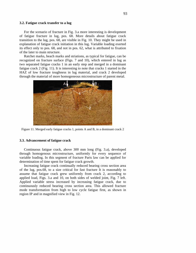
Ratchet marks, beach marks and striations, as typical for fatigue, can be recognized on fracture surface (Figs. 7 and 10), which entered in lug as two separated fatigue cracks 1 in an early step and merged in a dominant fatigue crack 2 (Fig. 11). It is interesting to note that cracks 1 started in the HAZ of low fracture toughness in lug material, and crack 2 developed through the material of more homogeneous microstructure of parent metal.
Figure 11. Merged early fatigue cracks 1, points A and B, in a dominant crack 2
3.3. Advancement of fatigue crack
Continuous fatigue crack, above 300 mm long (Fig. 3.a), developed through homogenous microstructure, uniformly for every sequence of variable loading. In this segment of fracture Paris law can be applied for determination of time spent for fatigue crack growth.
Increasing fatigue crack continually reduced bearing cross section area of the lug, pos.68, to a size critical for fast fracture It is reasonably to assume that fatigue crack grew uniformly from crack 2, according to applied load, Figs. 3.a and 10, on both sides of welded joint, Fig. 7 left. Applied variable stress increased by increasing fatigue crack, due to continuously reduced bearing cross section area. This allowed fracture mode transformation from high to low cycle fatigue first, as shown in region IP and in magnified view in Fig. 12.

D. Daničić, S. Sedmak, I. Blačić
3.4. Stable crack growth by ductile fracture
Three regions of stable crack growth by tearing fracture had been registered in Fig. 3.a. They occurred when applied maximum stress in analyzed component locally exceeded yield stress of material, the energy had been consumed for tearing fracture and crack tip blunting, followed by shear lips and development of stretch zone, according to maximum shear stress, under 45° to acting force. But among these three regions there is the difference in starting condition. In the case on the left side (Fig. 3a) high cycle fatigue preceded stable crack growth, which had been arrested by final stretch zone (FSZ) in the region ZP. At the end of FSZ final fast fracture took place. On the right side, in the region IP (Fig. 12) low cycle fatigue preceded the tearing segment CA, which had been arrested by FSZ (Fig. 13). After this new FSZ, crack had to continue to grow, again by tearing fracture, up to the formation of FSZ before final fast fracture.
It is to notice that in all three cases plane stress dominated and shear lips are present. However, the sequence of occurrence individual tearing fracture regions is not clear and request further analysis.
Figure 12. Transition from flat fatigue
fracture surface, with visible beach marks and less visible striation, to stable tearing,
region IP in Fig. 3
Figure13. Final stretch zone after developed shear lips prior the next
stable growth of ductile crack, corresponding to region CA in Fig. 3
95
After stress redistribution, fatigue crack continued to grow continuously, by low cycle process beyond final stretch at CA and by high cycle process on the other side, up to simultaneous transition to tearing mode on both sides. Fracture process ended by fast fracture on both ends, after probably simultaneous development of final stretch zones (FSZ).
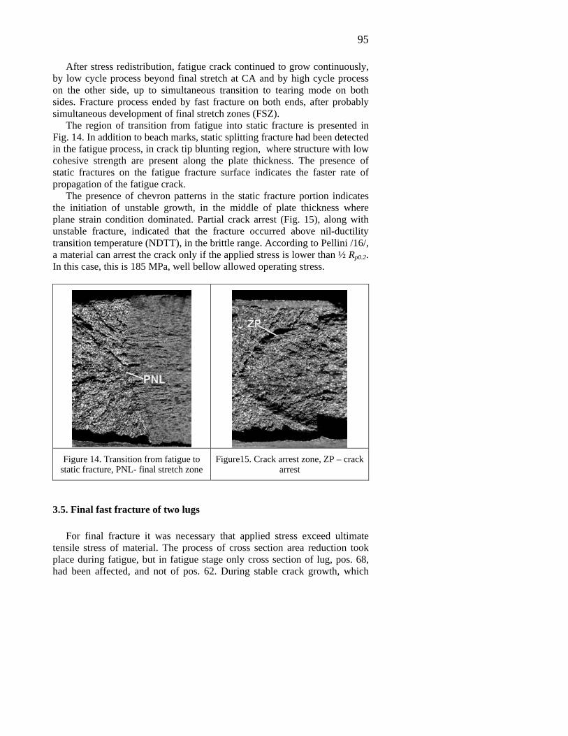
The region of transition from fatigue into static fracture is presented in Fig. 14. In addition to beach marks, static splitting fracture had been detected in the fatigue process, in crack tip blunting region, where structure with low cohesive strength are present along the plate thickness. The presence of static fractures on the fatigue fracture surface indicates the faster rate of propagation of the fatigue crack.
The presence of chevron patterns in the static fracture portion indicates the initiation of unstable growth, in the middle of plate thickness where plane strain condition dominated. Partial crack arrest (Fig. 15), along with unstable fracture, indicated that the fracture occurred above nil-ductility transition temperature (NDTT), in the brittle range. According to Pellini /16/, a material can arrest the crack only if the applied stress is lower than ½ Rp0.2. In this case, this is 185 MPa, well bellow allowed operating stress.
Figure 14. Transition from fatigue to
static fracture, PNL- final stretch zone Figure15. Crack arrest zone, ZP – crack
arrest
3.5. Final fast fracture of two lugs For final fracture it was necessary that applied stress exceed ultimate
tensile stress of material. The process of cross section area reduction took place during fatigue, but in fatigue stage only cross section of lug, pos. 68, had been affected, and not of pos. 62. During stable crack growth, which

D. Daničić, S. Sedmak, I. Blačić
preceded the final fracture, the reduction of cross section continued, still only of pos. 68. When total residual area of bearing cross section in both lugs had been reduced to a minimal value instantaneous fast fracture occurred, but by tearing mechanism. For the balance of applied load between different residual cross sections of two lugs, the load had to be redistributed, that means pos. 62 accepted greater part of the load than pos. 68.
This process had ended by development of first local final stretch zone CA. Simultaneously fatigue process might continue on lug other side up to the crack arrest and second final stretch zone ZP produced. When the stresses on both sides were balanced after strain energy had been consumed by final stretch zones development, last ductile stable crack had grown beyond CA location. This step finished by reached third final stretch zone. In this very moment bearing total cross section area of both lugs, pos. 68 and pos. 62, was reduced to the value critical for instant fast fracture.
The examination of the fracture surface of the position 62 showed the chevron pattern indicating that the fracture started in the weld metal, in the area between the two passes, Fig. 3.10. Generally, the occurrence of the unstable crack growth is typical for all the constituents of the welded joint and the parent material. Since no cracks have been arrested during the fracture of the position 62, one can say that, based on Pellini’s analysis /16/, the stress applied in the cross section was above ½ Rp0.2. This fracture has another typical characteristic: there are no shear lips on the fracture surface.
4. DISCUSSION
From theoretical point of view it is interesting to analyze the levels of applied stress and material response in different stages of considered fracture and the rates of crack growth, going back from final separation. This might help to better understanding of fracture mechanism and process duration.
Material will be separated if the applied stress exceeds ultimate tensile stress (UTS). However, it can happen at global level, for average value of applied stress, but also it can be sufficient if it happened locally, where stress concentration increases the value of average stress well above UTS. For tearing fracture the applied stress has to be in average higher than yield strength (YS) of material, accounting with stress concentration again. If the maximum value of applied variable load is slightly lower than YS, low cycle fatigue is most probable mode of cracking. The value of stress for high cycle fatigue should be lower than YS.
Rate of crack advancement also corresponds to fracture mode. For unstable fracture the rate is very high, the fracture occurred in very short time period, almost instantaneously. The rate of stable crack growth by tearing is lower, and for final separation, after final strength zone formation,
97 determined time is necessary. Low cycle fracture occurs in the range of cycle of variable loading (e.g. 50 000 to 100 000 cycles. For high cycle fatigue long time is required for crack development, measured by more than one million cycles.
It is also important to consider local microstructure for the evaluation of time necessary for individual steps of fracture.
The more detailed analysis of applied stress level, crack growth rate and microstructure investigation of welded joint is necessary for the evaluation of time period required for individual steps in presented fracture.
Roughly, of 17 years of BWE operation, it might be proposed that 70% of time had to be spent for high cycle fatigue, and the rest for crack initiation and early development in weld metal.
In the case of BWE fracture more interesting is practical engineering aspect of considered fracture, directed to the possibility how to avoid crack occurrence and how to prevent so difficult collapse and its consequences.
Fracture initiated from cracks in critical welded joint. The problem would not appear if this welded joint is not introduced in a structure of the counterweight. It is likely that, after experience with BWE failure, the design solution without welded joint of that kind is possible.
Next question is if the fatal collapse could be prevented by proper action during BWE design and exploitation.
By introduction of ISO 9000 series standards for quality assurance and ISO 9001 and ISO 9002 for quality systems welding is defined as "special process" because welded joints can not be fully inspected according to the standard requirements for a complete verification. In the case of welding, the quality can not be verified on the product but has to be built-in in the product. This generally accepted approach is dictated by the nature of fabri-cation in welding. Anyhow, the quality of welded joint can be endangered: (1) by defects induced during manufacturing and service and (2) by inevitable heterogeneity in microstructure and mechanical properties, corres-ponding to the nature of welding process, consisting of applied heating - cooling cycles.
In design stage most important was the underestimated significance of this welded joint, classifying it as auxiliary, and quality assurance system was not applied, neither in fabrication, nor in inspection. As a consequence, many detected defects and imperfections induced during manufacturing of welded joint contributed to high stress concentration, and critical welded joint was not available for inspection during service. In addition, misbalance of load and reduction of lug thickness from 40 mm to 20 mm by design solution produced inconvenient stress distribution. So, the structure contained the cracks, developed in fabrication or during operation under variable loading. For sure they could be detected in a proper inspection system, but it was not provided. Time period of 17 years of operation

D. Daničić, S. Sedmak, I. Blačić
indicates that in corresponding inspection and maintenance system the failure might be prevented.
5. CONCLUSION
Considering the importance of safe operation of BWE and other equipment operating on surface mines, complex systems for safety have been established, mainly as governmental agencies. It includes also welding procedures.
This approach is the direct contribution of new inspection and maintenance approach, especially proactive maintenance /17/, because the time estimates based on the crack can set a time frame in which the cracks can be detected and repaired to avoid a collapse of the structure. Also, during the inspection may be extended, reducing maintenance costs. Concerning this approach set a time in which critical elements of the structure should be revised so as to prevent damage, applying correct non-destructive examination. It means that corrected time of steel structure inspection can be applied basing on this kind of estimates and make more efficient inspection and maintenance.
Given the levels of assessment, definitely oblige to do the experimental confirmation of the hypothesis that would be a continuation of this work.
6. REFERENCES
[1] M. Arsić “Korelacija zamorne čvrstoće i praga zamora zavarenih spojeva” (“Correlation between endurance and fatigue threshold of welded joints”), Ph. D. thesis, Priština, 1995. [2] M. Arsić, S. Sedmak, M. Sarvan:“Analiza uzroka pojave prslina na zavarenim spojevima konstrukcije rotora bagera SRs 1300.26/5.0”, International conference “Welding 96”, Beograd, 1996. [3] D. Daničić, T. Maneski, D. Ignjatovic: Diagnostic approach to steel structure maintenance to prevent mining machine fractures, New Trends in Fatigue and Fracture, Metz 2010. [4] D. Daničić, T. Maneski, D. Ignjatović: Structural Diagnostics and Behaviour of Bucket Wheel Excavator, IVK 1-2010,53-60. [5] D. Daničić, T. Maneski: Structure Failure of the Discharge boom of BWE C 700 S due to Dynamic Effects, IVK 1-2012, 43-46 [6] M. Berković, Numerical Methods in Fracture Mechanics, IVK 2-2004, 63-66 [7] M. Berković, S. Maksimović, A. Sedmak, Analysis of Welded Joints by Applying the Finite Element Method, IVK 2-2004, 75-84
99 [8] T. Maneski, D. Ignjatović, Dijagnostika čvrstoće konstrukcije - Structural Performance Diagnostics, IVK 1-2004, 3-8 [9] T. Maneski, D. Ignjatović, Sanacije i rekonstrukcije rotornih bagera - Repair and Reconstruction of Bucket Wheel Excavators IVK 1-2004,9-28 [10] T. Maneski, D. Ignjatović, Sanacije i rekonstrukcije transportera i odlagača - Repair and Reconstruction of Belt Wagons and Stackers, IVK 1-2004, 29-38. [11] M. Arsić, S. Sedmak: “Spektar opterećenja za zamorna ispitivanja zavarenih spojeva rotornih bagera”, Međunarodno savetovanje “Zavarivanje ´94”, Novi Sad, 1994. [12] D. Daničić: Diagnosis of Conditions and Behavior for Steel Structures of Mining Machinery, PhD Thesis, Belgrade 2010. [13] S. Sedmak, V. Grabulov, D. Momčilović, Chronology of lost structural integrity initiated from manufacturing defects in welded structures, IVK 1-2009, 39-50 [14] Standard DIN 22 261-2:2006-12, Bagger, Absetzer und Zusatzgeräte in Braunkohlentagebauen - Teil 2: Berechnungsgrundlagen [15] N. Zuber, H. Ličen, A. Klašnja-Miličević: Applied Remote Condition Monitoring of the Bucket Wheel Excavator, Istraživanja i projektovanja za privredu, Naučno-stručni časopis, Beograd 2009. [16] W.S. Pellini, Guidelines for fracture-safe and fatigue-reliable design of steel structures, The Welding Institute, Abington, Cambridge, 1983. [17] P. Jovančić, D. Ignjatović: Proactive monitoring system for main mining mechanization at open cast mines, IVK 1-2010, 11-20.


![Orthogonal cutting in Ceramic Matrix Compositeseprints.nottingham.ac.uk/41706/1/Fracture mechanics paper1.pdf · two-dimensional scenario [8]. The cutting mechanism in composite materi-als](https://static.fdocuments.us/doc/165x107/5cc3323a88c993af3f8c46fd/orthogonal-cutting-in-ceramic-matrix-mechanics-paper1pdf-two-dimensional-scenario.jpg)