
Sax, Stephen To: Kelley, Penny (ECY) Cc: Bullamore, Bryant; Boyd, Robyn; Becher, Dave; Kucharski,...
256
From: Sax, Stephen To: Kelley, Penny (ECY) Cc: Bullamore, Bryant ; Boyd, Robyn ; Becher, Dave ; Kucharski, Margaret ; Wornell, Greg ; Meade, Michelle ; Meadows, Greg (Consultant) Subject: RE: WQC 9011 FB&L Discharge of process water to Lake WA Date: Tuesday, May 24, 2016 2:25:23 PM Attachments: Reportable Event Report Medina 05 19 2016.docx Penny, Attached is the incident report from the non compliance event that occurred on 5/19. The quantify of process water that entered the lake was estimated to be 1-3 gallons. If you have any questions regarding this incident please contact me. Stephen Stephen J. Sax Environmental Compliance Team Lead SR 520, I-5 to Medina: Stage 1 Evergreen Point Floating Bridge and Landings Washington State Department of Transportation 3015 - 112th Ave NE, Suite 100, Bellevue, WA 98004-8001 425.576.7133 0ffice 206-713-9783 Cell P Please Reduce, Reuse, Recycle, Rethink From: Sax, Stephen Sent: Monday, May 23, 2016 10:43 AM To: Kelley, Penny ([email protected]) Cc: Bullamore, Bryant ([email protected]); Boyd, Robyn; Becher, Dave ([email protected]); Kucharski, Margaret ([email protected]) Subject: WQC 9011 FB&L Discharge of process water to Lake WA Penny, As a follow up to the voice mail I left your earlier today, this is a notification that on 5/19 an event occurred on the SR 520 FB&L project the was not in compliance with general condition E4 the WQC 9011. During the demolition of Span 41 of the old SR 520 Floating Bridge, North Star (demo subcontractor) was using water to control dust while the concrete was being broken up. KGM had several barges, floats and mats under the work area to contain the debris and water from the demolition. One of the barges had a slight list causing the mixture of process water and rainwater to migrate to one side. There was a containment berm around the barge. Some of the rainwater process water mix overtopped the berm and was discharged to Lake Washington. The discharge lasted approximately 1-5 minutes. The water leaving the barge was clear in color. Crews stopped the water and made sure no more could enter the lake. They used pumps to
Transcript of Sax, Stephen To: Kelley, Penny (ECY) Cc: Bullamore, Bryant; Boyd, Robyn; Becher, Dave; Kucharski,...

From: Sax, StephenTo: Kelley, Penny (ECY)Cc: Bullamore, Bryant; Boyd, Robyn; Becher, Dave; Kucharski, Margaret; Wornell, Greg; Meade, Michelle; Meadows,
Greg (Consultant)Subject: RE: WQC 9011 FB&L Discharge of process water to Lake WADate: Tuesday, May 24, 2016 2:25:23 PMAttachments: Reportable Event Report Medina 05 19 2016.docx
Penny, Attached is the incident report from the non compliance event that occurred on 5/19. The quantify of process water that entered the lake was estimated to be 1-3 gallons. If you have any questions regarding this incident please contact me. Stephen
Stephen J. SaxEnvironmental Compliance Team LeadSR 520, I-5 to Medina: Stage 1 Evergreen Point Floating Bridge and LandingsWashington State Department of Transportation3015 - 112th Ave NE, Suite 100, Bellevue, WA 98004-8001425.576.7133 0ffice 206-713-9783 CellP Please Reduce, Reuse, Recycle, Rethink
From: Sax, Stephen Sent: Monday, May 23, 2016 10:43 AMTo: Kelley, Penny ([email protected])Cc: Bullamore, Bryant ([email protected]); Boyd, Robyn; Becher, Dave ([email protected]); Kucharski, Margaret ([email protected])Subject: WQC 9011 FB&L Discharge of process water to Lake WA Penny, As a follow up to the voice mail I left your earlier today, this is a notification that on 5/19 an event occurred on the SR 520 FB&L project the was not in compliance with general condition E4 the WQC 9011. During the demolition of Span 41 of the old SR 520 Floating Bridge, North Star (demo subcontractor) was using water to control dust while the concrete was being broken up. KGM had several barges, floats and mats under the work area to contain the debris and water from the demolition. One of the barges had a slight list causing the mixture of process water and rainwater to migrate to one side. There was a containment berm around the barge. Some of the rainwater process water mix overtopped the berm and was discharged to Lake Washington. The discharge lasted approximately 1-5 minutes. The water leaving the barge was clear in color. Crews stopped the water and made sure no more could enter the lake. They used pumps to
remove the process/rainwater mix from the barge into tanks for storage and disposal. We are working with KGM to draft an incident report with additional information and will submit this to you when it is completed. If you have questions regarding this incident please contact me. Stephen
Stephen J. SaxEnvironmental Compliance Team LeadSR 520, I-5 to Medina: Stage 1 Evergreen Point Floating Bridge and LandingsWashington State Department of Transportation3015 - 112th Ave NE, Suite 100, Bellevue, WA 98004-8001425.576.7133 0ffice 206-713-9783 CellP Please Reduce, Reuse, Recycle, Rethink

Reportable Environmental Incident Report
05/19/2016
Subject: SR 520 Floating Bridge and Landings
Location: Medina (over water)
Incident Date/Time: 5/19/2016 10:00 AM Duration: 5 min Report Date: 5/19/2016 Agencies Notified: Ecology # Pending
Notified by KGM on 5/19/2016 National Response Center # 1148213 Notified by KGM on 5/19/2016 Washington Emergency Management # 16-1855 Notified by KGM on 5/19/2016 Washington Department of Fish and Wildlife WSDOT notified Stewart Reinbold on 5/20/2016 Washington Department of Ecology WSDOT notified Penny Kelley on 5/20/2016
Incident Description: During the demolition of span 41 of the old SR 520 Floating Bridge, North Star, the demolition subcontractor, was using water to control dust while the concrete was being broken up. Underneath the work area KGM had several barges, floats and mats in place to contain concrete debris and water from the demolition operation. One of the barges developed a slight list from being unevenly loaded. This resulted in some the water migrating to one side of it. There was a four inch containment berm lined with filter fabric around the perimeter of the barge. A mixture of rain/process water filled the barge past the top of the containment berm and some of it overtopped the berm and entered the lake. The slow discharge lasted approximately 1-5 minutes and the discharge quantity was estimated to be one to three gallons. The pH was measured at 11 and the water leaving the barge was clear in color. No injured or distressed fish were observed in the area. Corrective Mitigation: Crews turned off the hoses to stop the flow of water and made sure no further process water left the work area. They used pumps to remove and transfer the process/rainwater mix into tanks. Ongoing Prevention of Future Incidents: An observer will be onsite to monitor water levels in the containment area. Pumps and storage tanks will be ready to use when water
Reportable Environmental Incident Report
05/19/2016
is being applied. The quantity of water being used for dust control will be monitored to make sure it isn’t excessive.
From: Bullamore, BryantTo: Kelley, Penny (ECY)Cc: Sax, StephenSubject: FW: KG520 ECP REV4 AppxI CWQMPP Text 05.25.16 Edit DraftDate: Thursday, May 26, 2016 3:54:34 PMAttachments: image001.gif
image003.pngKG520 ECP REV4 AppxI CWQMPP Text 05.25.16 Edit Draft.docx
Penny, Attached are the revisions to the WQMPP for the demolition of the SR 520 floating bridge. The revisions are in red. These changes are based on our phone conversations the last few days. Please let us know if any further updates are required or if you need additional information. If you have any questions on any of the information please let me know. Bryant Bullamore, P.E.Project EngineerFloating Bridge and Landings ProjectSR 520 Bridge Replacement and HOV ProgramOffice phone 425-576-7042Cell phone 425-766-3233
From: John.Gage [mailto:[email protected]] Sent: Thursday, May 26, 2016 3:43 PMTo: Bullamore, BryantCc: [email protected]; Ben.Nelson; Robert.BrennerSubject: KG520 ECP REV4 AppxI CWQMPP Text 05.25.16 Edit Draft Bryant, See the attached updated CWQMPP per our conversation to provide to Ecology. Let me know if there are any questions.
John Gage, AEP, CSEM, LEED APEnvironmental Manager | Kiewit/General/Manson, A Joint VentureSR 520 Evergreen Point Floating Bridge3015 112th Ave N.E., Suite 100, Bellevue, WA 98004(p) 425-576-7138 (c) 817-789-2380
REVISION 5 Released for Construction
SR 520 Evergreen Point Floating Bridge and Landings Project
Environmental Compliance Plan
Appendix I Construction Water Quality Monitoring and Protection Plan (Order No. 9011)
Prepared for Submittal to Washington State Department of Transportation
Prepared by Floyd|Snider
On behalf of Kiewit/General/Manson, A Joint Venture
May 25, 2016

SR 520 Evergreen Point Floating Bridge and Landings Project
05/25/2016 REVISION 5 Page i Environmental Compliance Plan Appendix I: CWQMPP
Table of Contents
Table of Contents ........................................................................................................... i 1.0 Introduction ......................................................................................................... 1 2.0 Project Description ............................................................................................. 3
2.1 IN-WATER/OVER-WATER CONSTRUCTION ACTIVITY DESCRIPTION ........... 3 2.1.1 Establishment of the Temporary Eastside Staging Area ........................ 6 2.1.2 Cofferdam Construction/Removal and Pier 1 Construction .................... 7 2.1.3 Dredging Prior to Cofferdam Construction at Pier 1 ............................... 9 2.1.4 Backfilling of Post-Dredge Sloughing Areas at Pier 1 .......................... 11 2.1.5 Construction of the East Approach Temporary Work Trestle ............... 12 2.1.6 Drilled Shaft Construction .................................................................... 13 2.1.7 Anchor Installation ............................................................................... 14 2.1.8 East Approach Construction ................................................................ 15 2.1.9 Floating Bridge Superstructure Outfitting ............................................. 16 2.1.10 Connection of a New Side Sewer to the Existing Sanitary Sewer
Main .................................................................................................... 19 2.1.11 Assembly of Bridge Floating Components ........................................... 20 2.1.12 Discharge of Temporary Pontoon Ballast Water .................................. 20 2.1.13 Bridge Deck Grinding and Texturing .................................................... 21 2.1.14 Preparation and Application of Bridge Pigmented Sealer..................... 22 2.1.15 Maintenance Facility Dock Construction .............................................. 22 2.1.16 Shoreline Mitigation Project Construction ............................................ 23 2.1.17 Pontoon Repair Work in Floating Coffercell ............................................. 25 2.1.18 Existing Bridge Demolition – Deck, Girder, Crossbeam and
Column Demolition .............................................................................. 26 2.1.19 Existing Bridge Demolition - Pier and Footing Demolition ........................ 27 2.1.20 Existing Bridge Demolition - Anchor Pile Demolition ................................ 28 2.1.21 Existing Bridge Demolition - Pontoon Separation .................................... 28 2.1.22 Existing Bridge Demolition - Pontoon Ballasting ...................................... 29 2.1.23 Existing Bridge Demolition - Anchor Cable Removal ............................... 29
3.0 Water Quality Standards .................................................................................. 30 4.0 Monitoring Plan ................................................................................................ 32
4.1 MONITORING LOCATIONS AND SCHEDULE.................................................. 32 4.2 CONTINGENCY MONITORING ........................................................................ 33
4.2.1 Biological Opinion Monitoring Requirements ....................................... 33 4.2.2 Bridge Demolition and Underwater Demolition Monitoring
Variance .............................................................................................. 34 4.3 NON-COMPLIANCE .......................................................................................... 34
5.0 Monitoring Procedures and Equipment.......................................................... 36 5.1 MONITORING EQUIPMENT.............................................................................. 36 5.2 FIELD EQUIPMENT CALIBRATION AND MAINTENANCE ............................... 36
SR 520 Evergreen Point Floating Bridge and Landings Project
05/25/2016 REVISION 5 Page ii Environmental Compliance Plan Appendix I: CWQMPP
6.0 Documentation and Reporting ........................................................................ 38 6.1 ADDITIONAL AGENCY REPORTING REQUIREMENTS .................................. 38
6.1.2 Bridge Demolition and Underwater Demolition Reporting Variance .............................................................................................. 38
7.0 Communications and Contacts ....................................................................... 41 8.0 References ........................................................................................................ 43
SR 520 Evergreen Point Floating Bridge and Landings Project
05/25/2016 REVISION 5 Page iii Environmental Compliance Plan Appendix I: CWQMPP
List of Tables
Table I.1 Project-Approved In-Water Work Windows
Table I.2 Water Quality Monitoring Schedule
List of Figures
Figure I.1 Floating Bridge and Landings Site Layout
List of Attachments
Attachment I.1 Project Linear Construction Schedule
Attachment I.2 Drilled Shaft, Anchor, Bridge Assembly, and Final Pontoon Ballast Water Discharge Plan Sheet and Water Quality Monitoring Locations
Attachment I.3 Pile Driving, Pier 1 Cofferdam Installation/Removal and Dredging, and Discharge of Temporary Pontoon Ballast Water Plan Sheet and Water Quality Monitoring Locations
Attachment I.4 Water Quality Monitoring and Protection Plan Monitoring Form

SR 520 Evergreen Point Floating Bridge and Landings Project
05/25/2016 REVISION 5 Page iv Environmental Compliance Plan Appendix I: CWQMPP
List of Abbreviations/Acronyms
Abbreviation/ Acronym Definition BMP Best Management Practice CSWGP Construction Stormwater General Permit CWQMPP Construction Water Quality Monitoring and Protection Plan ECM Environmental Compliance Manager Ecology Washington State Department of Ecology ECP Environmental Compliance Plan HPA Hydraulic Project Approval Kenmore Yard Kenmore Construction and Support Yard KGM Kiewit/General/Manson, A Joint Venture Medina City of Medina NGCS Next Generation Concrete Surface NMFS National Marine Fisheries Service NPDES National Pollutant Discharge Elimination System NTU Nephelometric Turbidity Unit OHWM Ordinary High Water Mark RFP Request for Proposal SPCCP Spill Prevention, Control, and Countermeasures Plan SR 520 FBL Project State Route 520 Evergreen Point Floating Bridge and Landings Project SR 520 FBL Site Floating Bridge and Landings Site USFWS U.S. Fish and Wildlife Service WAC Washington Administrative Code WDFW Washington Department of Fish and Wildlife WQC Water Quality Certification WQMPP Water Quality Monitoring and Protection Plan WSDOT Washington State Department of Transportation

SR 520 Evergreen Point Floating Bridge and Landings Project
05/25/2016 REVISION 4 Page I-1 Environmental Compliance Plan Appendix I: CWQMPP
1.0 Introduction
Kiewit/General/Manson, A Joint Venture (KGM) has prepared this Construction Water Quality Monitoring and Protection Plan (CWQMPP) for the Washington State Department of Transportation (WSDOT) to facilitate construction of the State Route 520 Evergreen Point Floating Bridge and Landings Project (SR 520 FBL Project). This document pertains to the in-water and over-water construction activities within the SR 520 limits of construction within Lake Washington and is not applicable to any other locations that may be used to support the project.
KGM will implement this CWQMPP for any in-water or over-water construction activities within the SR 520 limits of construction within Lake Washington. A water quality monitoring and protection plan (WQMPP) is required per the SR 520 FBL Project 401 Water Quality Certification (WQC) and is intended to provide specific information on activities that will be performed within and/or over waters of the state, and provide a monitoring schedule for tracking the performance of best management practices (BMPs) used during in-water and over-water construction work within the project limits of the Floating Bridge and Landings Site (SR 520 FBL Site). For the SR 520 FBL Project, and per the WSDOT Request for Proposal (RFP), the project specific WQMPP is titled the Construction Water Quality Monitoring and Protection Plan (WSDOT 2010). The CWQMPP was also prepared per the requirements described in Section 2.8.3.2.3.1.3 of the WSDOT RFP, the Environmental Commitments List (Appendix C1 of the RFP), and the terms and conditions provided in Biological Opinions prepared by the U.S. Fish and Wildlife Service (USFWS) and National Marine Fisheries Service (NMFS) for the SR 520 FBL Project. This plan is submitted to WSDOT as Appendix I of the SR 520 FBL Project Environmental Compliance Plan (ECP).
Any changes to BMPs, procedures, and/or monitoring must be approved by the Washington State Department of Ecology (Ecology) prior to conducting the work. Approval is not necessary for minor adjustments to BMPs and/or procedures that are needed as the work is being done.
All waters generated from the land-based construction activities in the eastside uplands of the City of Medina (Medina), consisting of dewatered groundwater, stormwater, and uplands Pier 1 cofferdam dewatering effluent, will be managed under and must meet the requirements of the SR 520 FBL Project National Pollution Discharge Elimination System (NPDES) Construction Stormwater General Permit (CSWGP) for bridge and approach construction. The SR 520 FBL Site Temporary Erosion and Sediment Control and associated Stormwater Pollution Prevention Plan, and the SR 520 FBL Project Spill Prevention, Control, and Countermeasures Plan (SPCCP) provide descriptions of: the uplands construction activities, BMPs that will be implemented to reduce potential impacts to and protect Lake Washington, construction stormwater pollution prevention measures, and all discharge monitoring requirements per the CSWGP (Appendices B.2 and C of the ECP). The Concrete Collection, Containment, and Disposal Plan (CCDP) also includes BMPs to be implemented in the upland areas associated with concrete management, handling, and disposal (Appendix D of the ECP). The SPCCP also includes BMPs relevant to in-water and over-water activities.
The procedures defined in this CWQMPP will achieve the following goals:
• Document the performance of BMPs and procedures used within and over Lake Washington.

SR 520 Evergreen Point Floating Bridge and Landings Project
05/25/2016 REVISION 4 Page I-2 Environmental Compliance Plan Appendix I: CWQMPP
• Determine if Water Quality Standards are being met at the point of compliance as defined in Washington Administrative Code (WAC) Chapter 173-201A-200, “Fresh water designated uses and criteria.”
• Help to ensure compliance with the conditions of the 401 WQC for construction activities conducted below the Ordinary High Water Mark (OHWM) and over water.
This CWQMPP identifies the appropriate parameters to be monitored, monitoring locations, monitoring and sampling procedures, and the frequency of monitoring. It also contains the BMPs and construction procedures that will be used to reduce impacts to waters of the state during specific identified construction activities over waters and/or below OHWM. These elements are described in detail in the following sections, which refer to drawings when appropriate. This plan does not include BMPs and construction procedures for the demolition activities associated with the existing floating bridge. Demolition of the existing floating bridge is scheduled to occur from approximately December 2014 to summer 2015. Prior to the start of any demolition activities over water and/or below OHWM, an amendment to this CWQMPP will be submitted to Ecology for review and approval per the 401 WQC.

SR 520 Evergreen Point Floating Bridge and Landings Project
05/25/2016 REVISION 4 Page I-3 Environmental Compliance Plan Appendix I: CWQMPP
2.0 Project Description
The purpose of the SR 520 FBL Project is to build a six-lane floating bridge and landings as a component of the Interstate 5 (I-5) to Medina: Bridge Replacement and High Occupancy Vehicle (HOV) Project. Final construction and assembly of the SR 520 FBL Project will be completed in Medina, and over water on Lake Washington between Medina and the City of Seattle.
The SR 520 FBL Project involves several phases of work associated with construction of a new six-lane bridge that includes HOV lanes, bicycle/pedestrian facilities, and the ability to accommodate future light rail. The layout of the SR 520 FBL Project Site is presented in Figure I.1 and shows where the construction activities will be performed. The SR 520 FBL Site construction activities are described below:
• Mobilization activities.
• Construction of a temporary eastside construction staging area for outfitting and assembly of floating bridge components, and construction of a temporary work bridge at the Medina shoreline.
• Construction of the floating bridge structure, a fixed east approach, and transition structures between the fixed structures and floating bridge.
• Construction of a new floating bridge maintenance facility and dock located beneath the east approach structure.
• All aspects of floating bridge assembly, comprising temporary moorage, towing all pontoons to Lake Washington, assembly of the pontoon substructure, and installation of the superstructure and roadway deck.
• Deconstruction of the existing floating bridge and landing components.
• Site demobilization.
As stated above, an amendment to this CWQMPP for the activities associated with the demolition of the existing floating bridge and landings will be submitted at a later date for Ecology review and approval. The amendment will describe the specific demolition work activities, how the work will be conducted, and the BMPs that will be used to reduce impacts and/or protect waters of the state.
2.1 IN-WATER/OVER-WATER CONSTRUCTION ACTIVITY DESCRIPTION
Most of the work associated with the SR 520 FBL Project will occur below the OHWM and/or over Lake Washington. The lake is the only surface water within the project area. The discharge of polluting matter to waters of the state is a violation of the Washington State Water Pollution Control Law (RCW 90.48.080). This CWQMPP is intended to help prevent violation of that law.
All in-water work will be conducted during the in-water work windows identified in the Hydraulic Project Approval (HPA) and authorized by the Washington Department of Fish and Wildlife (WDFW) and as presented in Table I.1. The project baseline linear construction schedule is provided in Attachment I.1. The construction activity plan sheets and water quality monitoring locations are presented in Attachments I.2 and I.3. Throughout all in-water and over-water work KGM will ensure, through implementation of the BMPs described below, that all construction-related debris is collected and contained and that no debris, garbage, or fuel will enter the lake.

SR 520 Evergreen Point Floating Bridge and Landings Project
05/25/2016 REVISION 4 Page I-4 Environmental Compliance Plan Appendix I: CWQMPP
Visual monitoring for floating debris (trash, oil sheen, etc.) will be conducted and boats will be available during construction for debris retrieval.
During in-water and over-water activities conducted for bridge construction, KGM will comply with the SR 520 FBL Project 401 WQC (provided in Appendix A of the ECP). There are three types of water associated with bridge construction in-water and over-water activities that require management:
• Concrete Process Water: Concrete process water is defined as concrete slurry resulting from drilled shafts, grinding residue water, and any other concrete-derived waters. All concrete process water will be contained and collected for off-site upland disposal at a licensed facility.
• High pH Stormwater: High pH stormwater is defined as rainwater that falls on uncured “green” concrete during the first 7 days of the curing process. Stormwater that falls on uncured concrete will be contained, tested, and treated as necessary to ensure compliance with pH and turbidity water quality standards prior to discharge to the lake. If high pH stormwater mixes with concrete process water, then it becomes concrete process water and will be contained and collected for off-site upland disposal at a licensed facility.
• Work Area Stormwater: Work area stormwater is defined as rainwater that falls into bridge work areas of active construction that contain debris and/or stockpiled materials. These work areas will require that catch basins be blocked for water containment and collection. Work area stormwater will be contained, tested, and treated as necessary to ensure compliance with pH and turbidity water quality standards prior to discharge to the lake.
If rainwater falls onto clean, cured concrete surfaces and bridge work areas, it will be allowed to run off the structure or surface directly to the lake. Fully cured concrete surfaces, such as the bridge roadway or pontoons, will be regularly cleaned (e.g., sweeping, debris collection and removal, etc.) and managed under the provision of the SPCCP and the Collection, Containment, and Disposal Plan (Appendices C and D of the ECP) to allow stormwater to run off these structures directly to the lake.
The BMPs that will be implemented during the project and apply to all in-water and over-water construction activities are presented below:
• Daily vehicle and construction equipment inspection (e.g., leaks, drips, or maintenance needs).
• Vehicles will be inspected prior to entering any over-water work zone in accordance with the SPCCP (Appendix C of the ECP). Vehicles and equipment (including cranes) will be kept clean of excessive oil and grease build-up.
• When over-water fueling is necessary, the BMPs and procedures described in the SPCCP will be implemented. Temporary land-based fueling stations will be used to the extent practicable and will be located at least 50 feet away from the shoreline.
• Eco-friendly lubricants and fuel sources (e.g., vegetable-based hydraulic fluid) will be used for in-water construction where practicable.
• The over-water cranes (located on the work trestle), including the tower crane and crawler crane(s), are a relatively newer fleet of equipment that will be well maintained and regularly cleaned. Fueling BMPs, as described in the SPCCP, will be
SR 520 Evergreen Point Floating Bridge and Landings Project
05/25/2016 REVISION 4 Page I-5 Environmental Compliance Plan Appendix I: CWQMPP
implemented during all fueling operations. For crane storage overnight, BMPs, such as diapers and plastic, will be placed underneath the crane engines and maintained daily.
• Temporary construction staging areas will be constructed within the upland portion of the site and will include spill containment measures in accordance with the SPCCP and erosion control BMPs presented in the Temporary Erosion and Sediment Control Plan, SWPPP, and the NPDES CSWGP.
• Spill containment kits and visqueen plastic will be kept in multiple locations on-site and within construction vehicles/barges for easy deployment in the event of a spill.
• Oil containment booms to contain and localize any potential spills, and thus minimize pollution and to assist in the removal of any spilled oil, will be present and available during all construction activities.
• Absorbent materials will be placed under all vehicles and equipment on barges or other over-water structures. Absorbent materials will be applied immediately on small spills, and promptly removed and disposed of properly. An adequate supply of spill cleanup materials, such as absorbent materials, will be maintained and available in multiple locations on-site.
• For significant equipment repairs, off-site equipment repair shops will be used to the extent practicable.
• Tie downs and other methods will be used to secure materials to aid in preventing discharges to the lake via wind forces.
• Over-water work areas and temporary stockpile materials will be covered when not in use. Nets, tarps, platforms, scaffolds, blankets, barges, and/or floats will be used as necessary to contain and control debris beneath structures being constructed.
• Curbing, bull rails, or toe boards will be installed around the perimeter of work trestles, platforms, and barges, as appropriate, to contain potential spills and prevent materials, tools, and debris from leaving the over-water structures. These applications will be installed with a minimum vertical height appropriate to contain runoff water. All concrete process water, as defined above, will be contained and collected for off-site disposal.
• Weather forecasting will be used to schedule concrete pour periods during fair weather conditions and allow for the early implementation of BMPs prior to predicted storm events to avoid and minimize any releases.
• “Pour Watches” will occur during all concrete pour events for health and safety, construction quality control, and release or spill prevention. Pour Watches will include inspection of formwork integrity and containment of all concrete process water.
• Formwork soffit systems will have edge forms and containment curbing systems that will contain concrete cure water and rainfall on curing concrete, so that the water can be collected and treated.
• Concrete will be poured in the dry or in conditions when rainwater falling on freshly poured uncovered concrete can be contained and collected for off-site disposal. Rainwater falling on freshly poured, uncured concrete will be considered high pH stormwater. High pH stormwater will be contained, tested, and treated as necessary to ensure compliance with the pH and turbidity water quality standards prior to
SR 520 Evergreen Point Floating Bridge and Landings Project
05/25/2016 REVISION 4 Page I-6 Environmental Compliance Plan Appendix I: CWQMPP
discharge to the lake. Concrete will be allowed to cure for at least 7 days before contact with surface water.
• When not in immediate use, Eco-Pans will be covered to prevent rainwater accumulation and minimize the generation of water requiring handling, treatment, and disposal, and to minimize the risk of a release of high pH stormwater or concrete process water.
• Concrete pumps and pipelines will be equipped with emergency cut-off valves so that no uncured concrete comes into contact with surface water.
• When construction activities are occurring on the bridge in work areas where water must be collected and treated (Work Area Stormwater), catch basins will be blocked to collect and contain construction waters.
• Treatment will include pumping the ballast water to a temporary holding tank, allowing the turbidity to settle, and treating for pH via a CO2 bubbler or other approved BMP designed to reduce pH to within an acceptable discharge limit, as necessary.
• Barges used for construction will not be allowed to ground within the project area.
• Barges and other floating equipment shall be operated so that there is minimal suspension of nearshore sediments.
Bridge construction will include the specific in-water and over-water activities described in the following sections.
2.1.1 Establishment of the Temporary Eastside Staging Area
One of the first in-water work activities on this project will be the installation of dolphins and anchors for the construction of the eastside staging area that will be used for pontoon outfitting and assembly. The staging area will be located approximately 450 feet from the eastern shoreline of Lake Washington, as shown in Figure I.1.
The eastside staging area will utilize 4 temporary pile anchor dolphins (each consisting of four (4) 30-inch diameter steel piles) and 10 temporary Danforth-type anchors within the WSDOT right-of-way to hold the pontoons in place as they are being assembled and outfitted. Danforth-type anchors are commonly used lightweight boat anchors. The temporary pile anchor dolphins will be located on the east end of the staging area. They are required (rather than Danforth-type anchors) in this location because a rigid temporary anchoring system with lateral stability is necessary to prevent the pontoons from moving east to west and damaging the existing bridge during storm events. Temporary piles will be driven by vibratory hammer to the maximum extent possible; however, to resist the lateral and vertical loads that are expected on these piles, pile installation will likely require proofing with an impact hammer following vibratory installation.
The westside staging area will utilize 8 temporary pile anchor dolphins (each consisting of three (3) 36-inch diameter steel piles) within the WSDOT right-of-way to construct two (2) temporary storage rafts for pontoon and barge storage. The temporary pile anchor dolphins will be located on the west end of the project north of the existing bridge. They are required in this location because a rigid temporary anchoring system with lateral stability is necessary to prevent the pontoons from moving east to west and damaging the existing bridge during storm events. Temporary piles will be driven by vibratory hammer to the maximum extent possible.

SR 520 Evergreen Point Floating Bridge and Landings Project
05/25/2016 REVISION 4 Page I-7 Environmental Compliance Plan Appendix I: CWQMPP
Water quality monitoring for turbidity will be conducted during pile-driving operations for the establishment of the temporary eastside and westside staging areas (Table I.2).
In addition to the BMPs listed Section 2.1 above, the following in-water BMPs will be implemented during installation of dolphins and anchors for construction of the eastside staging area:
• Pile driving will occur only during approved in-water work windows identified in the HPA and authorized by WDFW, or as otherwise authorized by WDFW to minimize the potential effects on fish species (Table I.1).
• Underwater sound attenuation in the form of a bubble curtain will be used during impact pile driving and underwater noise monitoring will be conducted (Appendix J of the ECP).
2.1.2 Cofferdam Construction/Removal and Pier 1 Construction
Another early in-water work activity on this project is the construction of a cofferdam and spread footing for Pier 1 (Attachment I.3). The cofferdam will be used to prevent sediment, concrete, and steel debris from mixing with waters of the state. The construction and removal of the cofferdam will occur only during the in-water construction periods; however, once the cofferdam is installed, work inside the cofferdam can occur at any time. Two spread footings will be used for the new bridge and will exist below the mudline at a depth of approximately 2 to 4 feet, with only the bridge columns present at the mudline. Only one of the spread footings will be constructed in the water (Pier 1). The other, Pier 2, will be constructed in the upland area in Medina. The location of the Pier 1 in-water spread footing and cofferdam is presented in Attachment I.3.
The cofferdam will be constructed by vibrating template piles or beams to guide the sheet pile enclosure installation. Steel walers, frames, and struts will be installed and the sheet piles will then be vibrated about 20 feet into the substrate, around the perimeter of the walers. Interlock sealant may then be applied to sheet pile joints to keep them watertight.
After completion of the cofferdam, it will be dewatered and any trapped fish will be removed using approved WSDOT fish handling and exclusion protocols or appropriately adapted and approved methods as described in the Fish Handling Plan for KGM Operations at the Pier 1 Cofferdam (Appendix M.2 of the ECP). The area within the cofferdam will then be excavated below the existing mudline with a clamshell bucket (prior to any concrete work) and dewatered again, if necessary. All excavated sediment will be transferred to a barge, and hauled off-site for proper disposal.
Initial dewatering effluent (prior to concrete placement) will be pumped to a barge-mounted tank system for turbidity treatment. Once the suspended solids in the effluent have settled and the water is monitored to ensure compliance with turbidity water quality standards, the water will be discharged back into Lake Washington.
Following completion of excavation and initial dewatering of the cofferdam interior, and prior to the construction of the spread footing, rock fill material will be spread across the top of the soil. A 2-foot concrete slab will then be constructed within the entire interior area of the cofferdam. The cofferdam sheet piles will act as the formwork to contain the concrete, and the inward pressure of the lake water to the sheet pile walls will prevent any potential seepage or leakage

SR 520 Evergreen Point Floating Bridge and Landings Project
05/25/2016 REVISION 4 Page I-8 Environmental Compliance Plan Appendix I: CWQMPP
of concrete outside of the cofferdam interior. This concrete slab will provide a stable and safe work surface during the construction of the spread footing and Pier 1. Following initiation of concrete work within the cofferdam, water management will be consistent with and based on the types of water described above in Section 2.1. Concrete process water will be contained and collected for off-site upland disposal at a licensed facility. Stormwater that falls on uncured concrete (high pH stormwater) will be contained, tested, and treated as necessary to ensure compliance with pH and turbidity water quality standards prior to discharge to the lake. If high pH stormwater mixes with concrete process water, then it becomes concrete process water and will be contained and collected for off-site upland disposal at a licensed facility. Uncured concrete will be prevented from contacting waters of the state.
The concrete pier columns and pier table will be constructed with cast-in-place concrete, off of the spread footings and with the cofferdam still in place. The formwork and the cofferdam enclosure will provide secondary containment for the concrete column placement. Freshly poured concrete will be covered during curing. Water entering the cofferdam (i.e., rainwater or surface water seeps) that is not in contact with uncured concrete will be contained within the cofferdam and will be pumped to the barge-mounted tank for turbidity and pH treatment as needed, prior to discharge to the lake. Concrete will be delivered from a concrete pump truck equipped with a boom arm located on the east approach work trestle.
Following construction of the spread footing and columns, the excavated area within the cofferdam will be backfilled, the cofferdam filled with lake water, and then the cofferdam steel sheet piles will be removed by vibratory methods. The sheet pile removal will occur at a slow controlled rate to minimize turbidity.
Water quality monitoring for turbidity will be conducted during the installation and removal of the Pier 1 cofferdam. Water quality monitoring is limited to only the installation and removal of the cofferdam sheets because all spread footing construction will be conducted and contained within the cofferdam.
In addition to the BMPs listed in Section 2.1 above, the following in-water and over-water BMPs will be implemented during cofferdam construction and removal and Pier 1 construction:
• The formwork used during cast-in-place concrete column construction will be secure, preventing any leaks of cure water or concrete, and concrete Pour Watches will be conducted. Visual monitoring will be conducted following the placement of the forms to ensure that the forms are secure.
• Eco-Pans and visqueen plastic will be used underneath the concrete hopper on the work trestle where concrete from the concrete trucks enters the system and a concrete pump pushes it through the slick line or pump boom.
• When not in immediate use, the Eco-Pans will be covered to prevent rainwater accumulation, minimize the generation of water requiring handling, treatment, and disposal, and to minimize the risk of an Eco-Pan release.
• Backfilled surfaces will be stabilized within the cofferdam, the cofferdam will be filled with lake water, and turbidity settlement within the cofferdam will occur prior to removing the cofferdam sheet piles.
• To minimize turbidity, the cofferdam sheet piles will be gradually removed with vibratory methods.
SR 520 Evergreen Point Floating Bridge and Landings Project
05/25/2016 REVISION 4 Page I-9 Environmental Compliance Plan Appendix I: CWQMPP
• All material used for the temporary cofferdam structure will be removed and properly disposed of off-site.
2.1.3 Dredging Prior to Cofferdam Construction at Pier 1
As described above, the Pier 1 cofferdam will be constructed by vibrating template piles or beams to guide the sheet pile enclosure installation. Steel walers, frames, and struts will be installed and the sheet piles will then be vibrated about 20 feet into the substrate, around the perimeter of the walers. Based on difficult pile driving at the uplands Pier 2 cofferdam location and at the Temporary East-side Staging Area (Figure I.1), it is anticipated that similar hard subsurface sediment conditions are present at Pier 1, since it is located between those two areas. To ensure that the cofferdam sheet piles are installed in their accurate locations given these hard sediment conditions, it is necessary to install the lower cofferdam frame to its final location prior to driving the sheet piles. The installation of the lower cofferdam frame will require pre-dredging of approximately 6,000 cubic yards of sediment, which is the total of the target 45,000 cubic yards plus an estimated additional 1,500 cubic yards of sloughing based on a 3V:1H repose. The dredge cut footprint is approximately 52 feet by 181 feet by 15 feet deep (Attachment I.3). Because the surface sediments (upper 5 feet of the sediment column) are not firm enough to support vertical sides, it is anticipated that the sides of the dredge cut will slough, or collapse, into the area being dredged. There may be additional sloughing that results from the vibratory installation of the sheet piling that will be used to construct the cofferdam. To account for all potential sloughing, including that directly resulting from dredging as well as from vibration during sheet pile installation, the estimated maximum area of impact is approximately 80 feet by 210 feet by 15 feet deep.
If determined to be necessary, prior to dredging, a total of 10 36-inch diameter steel pipe spuds will be installed with a vibratory hammer 50 feet from the neatline dredge cut and outside of the anticipated footprint of sloughing for vessel working on or in the cofferdam so the sheets or wale frame are not moved by vessel contact. If needed, the spud piles will remain in place for the duration that the cofferdam is in place to protect it from vessels and provide a means of mooring for vessels necessary to the cofferdam work, particularly those without their own spuds (e.g., concrete and rebar delivery barges). The installation of the spud piles may not be necessary if existing piling are sufficient for vessel mooring and to avoid vessel contact with the sheets and wale frame. If existing piling are not sufficient and without the spud piles, those vessels would otherwise have to be on anchors, some of which would extend into the navigation channel and present a navigation hazard. Following the installation of the spud piles, a full depth silt curtain (extending from the surface of the lake to the mudline) will be installed around the dredge cut footprint to contain any suspended solids or turbidity and aid in settling to reduce the potential impacts of dredging to the water column. The silt curtain will be secured to the spud piling around the perimeter of the dredged area at all times while dredging is occurring, eliminating the need to use anchors to secure the silt curtain and minimizing the additional suspended of sediments typically resulting from curtain anchors. Fish will be removed from within the silt curtain prior to the starting of dredging activities. The dredging will be completed in water depths of approximately 20 to 25 feet and within a lake environment that does not contain significant currents or tidal fluctuations. These conditions are favorable for use of a full depth silt curtain to contain turbidity. The area within the silt curtain (or the dredge cut footprint, including potential sloughing) is expected to encompass approximately 0.39 acres.
To exclude fish from the interior of the silt curtain, the silt curtain will be deployed doubled-up on itself. A skiff, or multiple skiffs, will tow the open end of the doubled-up curtain to the first piling, where it will be opened enough to allow it to encompass the first piling, then closed until the next
SR 520 Evergreen Point Floating Bridge and Landings Project
05/25/2016 REVISION 4 Page I-10 Environmental Compliance Plan Appendix I: CWQMPP
piling is reached. This process will be repeated until all 10 pilings have been included in the interior of the silt curtain. The two ends of the curtain will then be attached at the float, creating a cell that will enclose the dredging work while excluding fish. This method of silt curtain installation will reduce or eliminate the need for further efforts to exclude or herd fish out of the interior of the cell. If the bottoms of the curtain do not remain closed during movement, additional weight will be added to help keep them together so that fish are not inadvertently introduced into the cell. The cell will be checked visually to ensure that fish have been excluded prior to the commencement of dredging.
The sediments will be mechanically dredged with a standard clamshell bucket as the subsurface conditions prohibit the use of the Ecology bucket (e.g., environmental bucket). The dredged sediments will be loaded onto receiving barges, and transported to an off-site transload facility for upland disposal. During barge sediment dewatering, BMPs as described below will be implemented to minimize potential water quality impacts. If water quality exceedances occur, the release of dewatered return water will be staggered to provide a controlled release and prevent water quality criteria exceedances at the point of compliance, or the sediment water will be contained and pumped to a barge mounted or upland treatment area for turbidity removal. Alternatively, the sediment water will be contained and handled and removed at the off-site transload facility for upland disposal. Barge dewatering will be monitored per the water quality monitoring schedule in Table I.2.
Following completion of dredging, the interior of the silt curtain will be visually and physically inspected to ensure that turbidity levels are not too elevated prior to the removal of the silt curtain. If the turbidity is elevated to a level where an exceedance of water quality criteria may be expected at the 150 feet point of compliance, the silt curtain will not be removed until the suspended sediments have been allowed to settle. In the event that the suspended sediments consist of a small particle size and are not settling, the silt curtain will be slowly opened and closed in stages such that the silt curtain enclosure footprint is slightly reduced each time to provide a staggered and controlled release of the enclosed water. Water quality monitoring for turbidity will be conducted during the opening and closing of the silt curtain if this activity is required. Following the removal of the silt curtain the wale frames will be installed in preparation for driving the cofferdam sheet piles.
After the completion of the installation of the cofferdam sheet piles, the interior lake water will be dewatered using a pump with a compliant fish screen on the inlet hose and any fish present within the cofferdam will be removed. The cofferdam cell will be visually scanned for fish prior to the last bit of water being removed. If any fish are present, personnel will walk the sediment floor with a seine net or nets and remove the fish to an aerated cooler, which will be transferred for release in the lake. If the sediment floor is not firm enough to support personnel, a skiff or skiffs will be used to catch and remove fish with seine nets and dip nets. Following dewatering, the upper 5 feet of sediment from within the cofferdam will be excavated in the dry using standard excavation equipment and excavated sediments will be handled following the same best management practices as described below and in Section 2.1. The upper 5 feet of sediment that will be excavated in the dry following cofferdam construction is not being included in the pre-dredge activities due to concerns that dredging these sediments without dewatering could potentially jeopardize the quality of the subgrade material necessary for Pier 1 footing construction.
Water quality monitoring for turbidity will be conducted during all dredging activities, outside of the enclosed silt curtain at the point of compliance as identified in Section 4.0 and Table I.2.

SR 520 Evergreen Point Floating Bridge and Landings Project
05/25/2016 REVISION 4 Page I-11 Environmental Compliance Plan Appendix I: CWQMPP
In addition to the BMPs listed in Section 2.1 above, the following in-water BMPs will be implemented during sediment dredging:
• Use of a full depth silt curtain to contain all suspended sediment generated from the dredging work.
• Horizontal control for dredging operations will be achieved by careful tracking of clamshell bucket positions using an electronic positioning system that provides real-time display and tracking of the horizontal position of the dredge bucket.
• Receiving derrick barges will not be overfilled to the point where recovered sediment overflows directly back to the lake and barges will be suitably equipped to prevent spillage of turbid water while en route to the transload facility.
• Dredging will be conducted using procedures that will minimize potential impacts to water and sediment quality to the extent practicable. These procedures include the following:
∗ Stockpiling of material below MHHW will not be allowed (i.e., each time the bucket is closed it will be brought to the surface).
∗ The bucket will be required to pause for several seconds at the water surface during retrieval to release excess water.
∗ Ensuring that the bucket is completely emptied of sediments over the barge before re-submerging the bucket in the lake.
• Dredging will occur only during the most restrictive (i.e., shortest) approved in-water work window (East Approach Impact Pile Driving) identified in the HPA and authorized by WDFW, or as otherwise authorized by WDFW, to minimize the potential effects on fish species (Table I.1).
• Return water draining from the barge containing dredged sediment will be treated by filtering water through straw bales and/or geotextile fabric before returning to the lake.
• During sediment dewatering, the barge will remain within the project area.
• Return water from the barge will not be allowed to discharge to the lake outside the project area (e.g., during transport to a transloading site).
2.1.4 Backfilling of Post-Dredge Sloughing Areas at Pier 1
As described above, it is anticipated that the sides of the Pier 1 dredge cut will slough, or collapse, into the area being dredged and that there may be additional sloughing that results from the vibratory installation of the sheet piling that will be used to construct the cofferdam. The areas that have sloughed outside of the cofferdam sheet piles will be backfilled with either native sediment that was dredged or with washed gravel sized rock similar to that used in the shoreline habitat mitigation areas.
If native dredged sediment is used for backfill, a silt curtain attached to the cofferdam as described above would be installed prior to the start of backfilling operations which would provide a complete enclosure for backfill placement. The silt curtain would be moved as backfilling with native sediment occurs throughout the sloughed area(s). Fish will be removed from within the silt curtain prior to the start of backfilling activities. The dredged sediment would be placed in the sloughed areas with the use of a clamshell bucket.

SR 520 Evergreen Point Floating Bridge and Landings Project
05/25/2016 REVISION 4 Page I-12 Environmental Compliance Plan Appendix I: CWQMPP
Water quality monitoring for turbidity will be conducted during sloughed areas backfilling within the silt curtain. If dredged native sediments are used to backfill the sloughed areas the following in-water BMPs, in addition to those indentified in Section 2.1 with be implemented:
• Use of a full depth silt curtain to contain all suspended sediment generated from the backfilling work.
• Horizontal control for backfilling operations will be achieved by careful tracking of clamshell bucket positions using an electronic positioning system that provides real-time display and tracking of the horizontal position of the bucket.
If gravel is used for backfill, it will be accurately placed within the sloughed areas with use of a tremie line system and a barge-mounted hopper. A clamshell bucket will be used to load the gravel from a barge to the barge-mounted hopper. Water quality monitoring for turbidity will be conducted during the placement of the gravel in the sloughed areas. If washed gravel/rock is used to backfill the sloughed areas the following in-water BMPs, in addition to those indentified in Section 2.1 with be implemented:
• The gravel backfill will be placed in the barge-mounted hopper with a controlled clamshell bucket to minimize turbidity.
• Clean gravel backfill (i.e., without substantial fines) will be used to minimize turbidity.
• A tremie line will be used for accurate placement of gravel within the sloughed areas.
• During gravel loading to the hopper for backfilling, the clamshell bucket will be fully closed and not overfilled to prevent the release of any gravel between the supply barge and the hopper barge.
2.1.5 Construction of the East Approach Temporary Work Trestle
A temporary work trestle will be constructed along the east side of Lake Washington (Attachment I.3). The work trestle will consist of heavy timber decking supported by steel beams. The trestle will be supported by 23 24-inch steel piles and at the end of the trestle 13 24-inch steel piles will be installed to support a movable unloading ramp and an alignment dolphin. A vibratory hammer will be used to initially insert the temporary steel piles; however, an impact hammer will be used to complete the installation and confirm the load-bearing capacity of each pile at the end of the pile-driving process. During impact pile driving a bubble curtain sound attenuation device will be employed to completely surround the piles during impact driving.
Water quality monitoring for turbidity will be conducted during pile-driving operations for the construction of the east approach temporary work trestle.
In addition to the BMPs listed in Section 2.1 above, the following in-water and over-water BMPs will be implemented during construction of the temporary work trestle:
• Pile driving will occur only during approved in-water work windows identified in the HPA and authorized by WDFW, or as otherwise authorized by WDFW, to minimize the potential effects on fish species, unless otherwise authorized (Table I.1).
• Underwater sound attenuation in the form of a bubble curtain will be used during impact pile driving and underwater noise monitoring will be conducted.

SR 520 Evergreen Point Floating Bridge and Landings Project
05/25/2016 REVISION 4 Page I-13 Environmental Compliance Plan Appendix I: CWQMPP
• Material on the trestle will be secured with tie downs or similar devices and bull rails or toe boards will be installed around the perimeter of the work trestle to prevent any over-water releases of debris.
• The work trestle will be regularly swept and cleaned to prevent over-water releases of dirt, dust, or debris.
2.1.6 Drilled Shaft Construction
The fixed portions of the bridge on the west side of Lake Washington will be supported by reinforced concrete drilled shaft foundations. Four drilled shafts and concrete support columns will be constructed at the western terminus of the floating span to support the eastbound and westbound transition spans. Four approximately 12-foot diameter drilled shafts will comprise a single pier bent (Pier #36) of the future west approach span.
In addition, drilled shafts will be used for five shallow anchors where the use of gravity anchors would not allow for the required navigational water depth. Drilled anchor shafts are constructed the same as drilled shafts, but shaft anchors are smaller and approximately 10 feet in diameter. The locations of the drilled shaft and drilled shaft anchors are included in Attachment I.2.
Drilled shaft construction requires an initial installation of temporary piling and construction of a template to facilitate the precise placement of the shafts. Then a steel casing of specified diameter and length is installed and the interior of the shaft steel casing is excavated to a specified diameter and depth. Next, a steel reinforcing cage is installed and the interior of the shaft is backfilled with reinforced concrete, which for anchor construction ends at approximately 6 feet above the mudline, and for drilled shaft construction ends at approximately 7 feet above lake level. The shaft steel casing will be installed using a vibratory hammer, and the steel reinforcing cage is set inside the open shaft and hung at elevation.
During construction, the steel casing extends out of the water, containing all material within the casing and preventing releases to open water. The interior of the shaft casing will be excavated using an auger or clamshell bucket supported by a floating derrick. The excavated or augered spoils will be fully contained and will be loaded onto receiving barges and transported to an off-site transload facility for disposal. Since the drilled shafts are backfilled with concrete, displacing water and sediment material, and the concrete slurry is recirculated with the auger, the resulting waste slurry and all associated slurry waters and sediment will be pumped into barge-mounted waste bins and the barges will go to a transloading facility for off-site disposal. After the shaft casing is backfilled with concrete, the shaft casing will be cleaned out and then cut off by a diver at the top of the concrete or at the mudline.
Water quality monitoring for turbidity will be conducted during the installation of the drilled shaft casings. All other drilled shaft construction activities are contained within the casing, and all excavated sediments, concrete slurry, and slurry waters will be contained, collected for offsite disposal, and will not be allowed to discharge to the lake.
In addition to the BMPs listed in Section 2.1 above, the following in-water BMPs will be implemented during drilled shaft construction:
• The shaft steel casing will be installed with vibratory methods.
• Material excavated from within casing (slurry and sediment) will be loaded onto receiving barges that will not be overfilled to the point where material overflows directly back to the lake.

SR 520 Evergreen Point Floating Bridge and Landings Project
05/25/2016 REVISION 4 Page I-14 Environmental Compliance Plan Appendix I: CWQMPP
• Eco-Pans and visqueen plastic will be used to contain and collect any concrete or slurry drips to prevent spills.
• Barge-mounted slurry waste bins that will receive concrete and/or slurry water will be lined to prevent leakage.
• The tops of the shaft casings will be cleaned prior to cutting of the casing by either vacuum or agitation and pumping or air lift, depending on the depth of the drilled shafts and shaft anchors.
2.1.7 Anchor Installation
The new floating bridge will be secured in place three types of anchors. As with the existing bridge, the two primary anchor types will be gravity anchors for harder lake bed materials and sloped areas (likely 8 such anchors, near the shores), fluke anchors for soft bottom sediments and flat areas (likely 40 such anchors, middle of the lake), and 5 drilled shaft anchors in shallow areas of the lake, to the north of the new bridge on the east side of the lake, and to the south of the existing bridge near Pier 36, where gravity anchors would present a navigation hazard. Both the gravity and fluke types of anchors will be deployed using a barge-mounted crane. Drilled shaft anchors will be constructed using the same equipment and methodology as the drilled shafts as described above in Section 2.1.4. Following installation, anchors will be connected to the floating pontoons with high-strength steel cables. The locations of the gravity, fluke, and shaft anchors are presented in Attachment I.2.
Fluke anchors are installed using a combination of their own weight and water-jetting to set them below the mudline. Water supplied by pumps and hoses is jetted through pipes cast into the concrete anchors. As the high-pressure water exits the bottom of the anchor, it liquefies the soft substrate and allows the anchors to penetrate the substrate. Once fluke anchor installation has started, it cannot be stopped or the jet nozzles will become plugged and the fluke anchor would be stuck at the depth at which the jetting stopped. The typical duration of the installation of each fluke anchor is expected to be up to 8 hours, but could potentially be as short as 2 to 3 hours, depending on the site-specific sediment and equipment conditions. The depth of the fluke anchors prevents the use of containment BMPs to address turbidity. The water quality standards (WAC 173-201-200), as described in detail below in Section 3.0, are based on the aquatic life use of the lake, which will be Core Summer Salmonid Habitat. The approximate depth range at which elevated turbidity is a concern to potentially impact aquatic life is from the surface to approximately 40 to 60 feet below the water surface. The fluke anchors and associated water-jetting will be used for the deepest anchor locations, approximately 180 feet or more. Additionally, in June 2011, WSDOT conducted a study to summarize the potential effects on lake circulation from the new floating bridge, which will be deeper, longer, and wider than the current bridge. Lake Washington water temperature profiles that were collected between March and September in the years 2008, 2009, and 2010 indicate that seasonal stratification occurs in the shallow depths of the lake (between the surface and 65 feet), but that temperature does not vary at the deeper depths of the lake, below approximately 65 feet. Based on these temperature profile data that indicate lake water at deeper depths is not driven by surface mechanisms, turbidity at the deeper depths is not expected to affect the overlying shallow water. Therefore, the unavoidable turbidity that will be generated during installation of the fluke anchors is not expected adversely impact the aquatic life within the shallower depths of the lake. KGM will conduct visual water quality monitoring for turbidity plumes throughout the duration of fluke anchor installation. If a plume of turbidity is observed, documentation and contingency monitoring will occur, as described below in Section 4.2.
SR 520 Evergreen Point Floating Bridge and Landings Project
05/25/2016 REVISION 4 Page I-15 Environmental Compliance Plan Appendix I: CWQMPP
Gravity anchors are planned to be used in areas with harder lake bed materials and in sloped areas. Fill will be required to obtain level substrate surfaces for gravity anchor installation. The fill will consist of rock fill pads on the sloping portion of the lake bed. The rock fill will be barged into the work area, and will be placed with clamshell buckets. If excavation of the sloped substrate is required for gravity anchor installation, the excavated material will be placed out of the excavation and anchor installation area and will not be removed from the lake bed. Rock will be accurately placed within each of the four internal cells of the gravity anchor, once placed, with use of a tremie line system and a barge-mounted hopper. A clamshell bucket will be used to load the rock from a barge to the barge-mounted hopper.
Water quality monitoring for turbidity will be conducted during the installation of gravity anchors, including the excavation and/or leveling of sediments and the placement of the gravity anchor.
Shaft anchors will be constructed in the same manner as the drilled shaft foundation elements. Refer to Section 2.1.4 for the description of the drilled shaft construction activities and associated BMPs.
In addition to the BMPs listed in Section 2.1 above, the following in-water BMPs will be implemented during gravity anchor installation:
• The rock fill will be placed with a controlled clamshell bucket to minimize turbidity.
• Clean rock fill (i.e., without substantial fines) will be used to minimize turbidity.
• An environmental clamshell bucket will be used for the dredging/excavation of surface sediments as required for gravity anchor placement; however, in the event that the environmental clamshell bucket encounters debris or cannot successfully dig through the material, heavier digging using a standard clamshell bucket may be required.
• Controlled placement of any excavated material outside of the gravity anchor installation area to minimize turbidity.
• A tremie line will be used for accurate placement of rock within the interior gravity anchor cells.
• During rock loading to the hopper for gravity anchor filling, the clamshell bucket will be fully closed and not overfilled to prevent the release of any rock between the rock supply barge and the hopper barge.
2.1.8 East Approach Construction
The fixed portion of the east approach will be completed using the segmental concrete-balanced cantilever construction technique. This method will also be used for the construction of the bridge on top of the Pier 1 and Pier 2 columns.
Segmental concrete-balanced cantilever construction begins with construction of “pier tables” above the columns from which to begin construction of the balanced cantilever bridge sections. A pier crossbeam is constructed to connect the pier tables and then form travelers (which are mechanical formwork) will be installed on this initial segment of the bridge. The forms, including the soffit support system, will be extended out from the pier in both directions. Rebar will be installed and concrete poured to create cantilevered bridge sections extending from the pier. Concrete will be delivered from a concrete pump truck equipped with a boom arm located either on the uplands or on the work trestle, and possibly through the use of a slick line. All concrete

SR 520 Evergreen Point Floating Bridge and Landings Project
05/25/2016 REVISION 4 Page I-16 Environmental Compliance Plan Appendix I: CWQMPP
process water will be collected for disposal with appropriate BMPs described in Section 2.1 and below. High pH stormwater will be contained, tested, and treated as necessary to ensure compliance with the pH and turbidity water quality standards prior to discharge to the lake. In-water water quality monitoring will not be performed during east approach construction; however, contingency monitoring will be performed in the event of an unauthorized release as described in Section 4.2.
Following concrete placement, the bridge sections will be post-tensioned. As part of the post-tensioning process, steel reinforcing cables will be placed in ducts within the structure, the steel tensioned, and then the ducts pressure grouted. BMPs for pressure grouting are described below. Epoxy will also be used in the post-tensioning process with similar containment BMPs as those identified below for the pressure grouting work.
In addition to the BMPs listed in Section 2.1, the following over-water BMPs will be implemented during fixed bridge superstructure construction:
• Formwork soffit systems will have edge forms and containment curbing systems that will contain concrete process water, so that the water can be collected and treated.
• Eco-Pans and visqueen plastic will be used to contain and collect any concrete or slurry drips to prevent spills. Waste bins that will receive concrete and/or slurry water will be watertight.
• Eco-Pans and visqueen plastic will be used underneath the concrete hopper in the uplands or on the work trestle where concrete from the concrete trucks enters the system.
• Concrete line cleaning will be conducted by hand on the waste bin barges or other contained areas to minimize potential releases. Grout, followed by water, and then a final sponge “rabbit” will be pushed through the concrete line to ensure removal of all concrete within the line for line maintenance and prevention of line failures after each pour.
• Dry grout bags will be stored under plastic cover.
• A small portable grout mix plant will be used for grout preparation. Grout preparation, including the grout mix plant placement, will be conducted within areas that have secondary containment, using Eco-Pans, visqueen plastic, and temporary curbing.
• Eco-Pans and visqueen plastic or plastic containment buckets will be used at the ends of post-tensioning ducts to contain and collect any grout and/or epoxy and to prevent spills.
2.1.9 Floating Bridge Superstructure Outfitting
Floating bridge superstructure outfitting consists of the construction of bridge superstructure and roadway decking on the top of the pontoons. Pontoon outfitting includes constructing the columns that support the roadway, installing pier cross beams between the columns, and placing and connecting the precast concrete roadway deck panels.
There are five pontoon assembly cycles anticipated for the eastside staging area. Up to 16 pontoons would be present in the eastside staging area at any given time during the 3-year construction period. Temporary moorage and outfitting at the eastside staging area could last up to 3 months for each cycle of pontoons. On-site outfitting will initially commence at the eastside staging area. Outfitting efforts could continue at this location until the next complete cycle of

SR 520 Evergreen Point Floating Bridge and Landings Project
05/25/2016 REVISION 4 Page I-17 Environmental Compliance Plan Appendix I: CWQMPP
pontoons arrives from the fabrication sites, or just prior to the arrival of the new pontoons all completed work may be shifted to the permanent bridge location where outfitting will be completed.
Most of the bridge superstructure to be installed on the pontoons is comprised of pre-cast concrete components that will be constructed in upland controlled environments and will be barged to the eastside staging area for installation. Cast-in-place concrete columns will be constructed on the pontoons to support pre-cast cross beams, girders and deck panels. Small-scale “closure pours” of cast-in-place concrete will be used to connect deck panels and cross beams. Following completion of the concrete work, the superstructure components will be post-tensioned. As part of the post-tensioning process, steel reinforcing cables are placed in ducts within the structure, the steel is tensioned and then the ducts are pressure grouted. BMPs for pressure grouting are described below. Epoxy will also be used in the post-tensioning process with similar containment BMPs as those identified below for the pressure grouting work.
For outfitting work, all cast-in-place concrete work will be conducted above the pontoon surface. Each area where cast-in-place concrete work is conducted will have operational surrounds to collect and contain concrete process water. Derrick barge-mounted cranes will be used for handling and installation of the precast concrete components placed on the pontoons in the eastside staging area.
For outfitting operations, concrete will be delivered to either the eastside staging area or the bridge final alignment by two different mechanisms. Concrete will be provided to the eastside staging area using a hard-line pumping system (slick line) from a fixed location adjacent to the existing bridge on the Medina uplands, and/or concrete will be provided to the bridge final alignment via moored barges and concrete trucks. For this delivery system a barge will be moored off of the work trestle ramp, and another barge will be moored off the other side of the primary barge. The moored barges form a rigid, solid “barge bridge” that connects to the pontoon that will be outfitted. Concrete trucks would then be able to drive down the work trestle platform, down the ramp, and across the barge bridge to deliver concrete to the pontoons via the truck hopper. When the barge bridge is in use for concrete delivery the barges will be spudded down; however, when concrete is not being delivered, the barge spuds will be pulled up and the barges will relocate. The barge bridge used for concrete delivery provides a rigid working platform, and the same BMPs that will be implemented during concrete delivery via the eastside staging area will be employed during operation of this delivery system. Concrete trucks supplying concrete to the eastside staging area and bridge final alignment for outfitting will ingress/egress at the Medina property, adjacent to Evergreen Point Road.
Washout areas and procedures will be established on-site for all concrete-related activities. As described in the CCDP (Appendix D of the ECP) concrete trucks will not be washed out into storm drains, open ditches, streets, or streams. Concrete washout facilities will be located a safe distance away from storm drains or open drainage facilities, and a minimum of 50 feet away from water bodies, and away from construction traffic or access areas to prevent disturbance.
A concrete slick line delivery system would run from the abutment of the existing east high-rise, eastward along the edge of the existing bridge and newly constructed employee access walkway, down to the existing pontoons, and then laterally to the staging area. Redi-mix concrete trucks would deliver concrete to one or more line pumps located at the east abutment; from there, the concrete will flow through piping to the staging area. As pontoons are added from the east to the west, the delivery system will be extended with each pontoon. The total planned length of the system is approximately 2,500 feet. Flexible connections utilizing steel
SR 520 Evergreen Point Floating Bridge and Landings Project
05/25/2016 REVISION 4 Page I-18 Environmental Compliance Plan Appendix I: CWQMPP
reinforced concrete pump hoses will be used where necessary at transition points, and for connections to the placement boom. Custom-made brackets will be used to clamp the line to the existing bridge and access walkways to cross over to the staging area.
At the end of each concrete pour the line will be cleaned by discharging the remaining concrete in the line into lined waste bins (approximately 10 cubic yards in size) located on pontoons or barges. The boom connected to the pipeline will extend to the waste bins over visqueen plastic, to prevent any over-water releases. The bins will be transported off-site and replaced as required. The concrete waste within the waste bins will be removed off-site for proper disposal.
Any rainwater that falls on the uncured concrete components during the first 7 days of curing will be considered High pH stormwater. High pH stormwater will be contained and tested to ensure compliance with the pH and turbidity water quality standards prior to discharge to the lake. In-water water quality monitoring will not be performed during superstructure outfitting; however, contingency monitoring to be performed in the event of an unauthorized release as described in Section 4.2. In addition to the BMPs listed in Section 2.1 above, the following over-water BMPs will be implemented during superstructure outfitting and concrete delivery:
• Eco-Pans will be used underneath the concrete hopper on the barge where concrete from the concrete trucks is provided to the pontoons.
• Concrete trucks and/or equipment will not be washed out or cleaned on the barge bridges. All concrete cleaning will be done in an upland-designated washout area with containment BMPs (refer to the CCDP, Appendix D of the ECP).
• Eco-Pans and visqueen plastic will be used to contain and collect any concrete or slurry drips to prevent spills. Waste bins that will receive concrete and/or slurry water will be watertight.
• Dry grout bags will be stored under plastic cover.
• A small portable grout mix plant will be used for grout preparation. Grout preparation, including the grout mix plant placement, will be conducted within areas that have secondary containment, using Eco-Pans, visqueen plastic, and temporary curbing.
• Eco-Pans and visqueen plastic or plastic containment buckets will be used to contain and collect any grout and/or epoxy and to prevent spills.
• Temporary curbing will be installed in each area where concrete is being poured. Concrete process water will be contained within the temporary containment area with curbing and visqueen plastic.
• Edge forms will be used to fully contain concrete process water and high pH stormwater.
• Formwork will be secure and watertight to fully contain all concrete process water and high pH stormwater.
Additional BMPs if the concrete slick line delivery system is used:
• The concrete pumps that feed the slick line will be placed at the east abutment because it is the closest point to the water line that truck access can be established (due to the very steep slope).
• The piping system will be located on the employee access walkways to the staging area such that it can be continuously inspected and maintained.

SR 520 Evergreen Point Floating Bridge and Landings Project
05/25/2016 REVISION 4 Page I-19 Environmental Compliance Plan Appendix I: CWQMPP
• Concrete slick line containment BMPs, such as Eco-Pans and visqueen plastic, will be readily available and focused on the flexible joints of the line, which are more vulnerable to wear and tear and leaks than the rigid portions of the line. The concrete slick line will continuously be inspected to ensure integrity and conduct preventive maintenance (e.g., if any sections of the pipe appear weak or thin, or small leaks are noted the line will be depressurized, shut off, opened, cleaned and repaired, and reconnected).
• The concrete pipeline will be supported upon the decking of the main access walkways with toe boards, which will serve as secondary containment along the majority of the routing.
• Eco-Pans will be used underneath the concrete hopper on the uplands where concrete from the concrete trucks enters the system and a concrete pump pushes it through the pipeline.
• The concrete pipeline will be rigid steel pipe with restrained gasketed joints. During line connections or during cleaning, secondary containment BMPs, such as Eco-Pans and visqueen plastic, will be readily available and used.
• Concrete line cleaning will be conducted by hand on the waste bin barges or other contained areas to minimize potential releases. Grout, followed by water, and then a final sponge “rabbit” will be pushed through the concrete line to ensure removal of all concrete within the line for line maintenance and prevention of line failures after each pour.
2.1.10 Connection of a New Side Sewer to the Existing Sanitary Sewer Main
An existing City of Bellevue lake line sewer main runs north to south along the Medina shoreline. The sewer line is located approximately at the lake water’s edge, although the elevation and horizontal location varies along the shoreline. At the Medina property for the SR 520 FBL Project, a clean-out, where an existing side sewer joins the main, is located underneath an existing private dock at the northern right-of-way boundary. As part of KGM’s work for the SR 520 FBL Project, the dock will be demolished and KGM will construct a new 8-inch ductile iron side sewer line that will connect to the City of Bellevue’s lake line sewer main, near the existing side sewer connection. The existing lake line sewer main is located along the shoreline at the edge of the lake water level. The work to be performed to connect the new side sewer line to the existing lake line sewer main is expected to consist of limited hand digging or excavation with small equipment of the shoreline sediment around the existing line in approximate dimensions of 2 to 3 feet wide and 2 to 3 feet deep. The work will be conducted in the dry as much as possible and blocked off from the lake with the use of a temporary dam constructed of sandbags or equivalently effective BMP. The location of the existing side sewer connection and the location of the new side sewer line are shown on the Medina TESC site plans (refer to Appendix B.2 of the ECP).
Water quality monitoring will be performed for turbidity during the shoreline sewer line connection activities.
In addition to the BMPs listed in Section 2.1 above, the following in-water BMPs will be implemented during the connection of new side sewer line:
• Work will be conducted as expediently as possible for the disturbance of the shoreline sediment and sewer line connection. Work will be targeted to be performed

SR 520 Evergreen Point Floating Bridge and Landings Project
05/25/2016 REVISION 4 Page I-20 Environmental Compliance Plan Appendix I: CWQMPP
during lower lake water levels to maximize the duration of the work to be completed in the dry and minimize the amount of water to be displaced.
• The sewer line work area will be blocked off from the lake with a temporary dam constructed of sandbags or equivalent.
• All work activities will be conducted by equipment located at the top of bank, or by hand within the work area. Excavated material will be immediately placed in the upland area of the site and appropriately managed per the Temporary Erosion and Sediment Control (TESC) requirements.
• After the new surfaces within the work area are stabilized, the sandbag dams or equivalent will be removed in a manner to minimize the generation of turbidity.
• Upon completion of the sewer line connection work, all material used for the construction of the temporary dams will be removed from the site and the site returned to the pre-project or improved conditions.
2.1.11 Assembly of Bridge Floating Components
Prior to superstructure outfitting, pontoons will be joined into clusters. To join pontoons, divers will clean the joining ends of the pontoons via pressure washing, remove temporary towing plugs, and install rubber seal elements. Once pontoons have been brought together with the help of tugs or boats, assembly bolts will be installed, and the watertight joints will be dewatered with a small electric pump and grouted. Once the pontoon joining is completed, the temporary anchors will be removed and the joined pontoons, now a completed section of the bridge, will be towed to the final bridge position.
Once the joined pontoons are in final bridge position, anchor cables will be connected and the sections of the bridge and pontoons to be joined will be pressure washed before assembly. pH water quality monitoring adjacent to the pontoon or bridge surface being cleaned will be conducted during pressure washing. Since these concrete floating bridge components will be fully cured prior to towing, any rainwater on the surfaces will be allowed to run off directly into the surface water.
The BMPs described in Section 2.1 above will be implemented during the assembly of the floating bridge components.
2.1.12 Discharge of Temporary Pontoon Ballast Water
Each pontoon used in constructing the new bridge will contain both rock and water ballast. Ballast water is required in order to make adjustments to trim and level the pontoons during outfitting and assembly. Prior to towing the pontoons to Lake Washington, the inside cells of the pontoons to receive ballast water will be cleaned at the casting facility (the Concrete Technology Corporation Pontoon Casting Facility Tacoma or Grays Harbor) to remove dust and debris before the ballast water is placed in the cells. The water ballast added to the pontoons at the CTC Facility and Grays Harbor will be fresh water, likely from the fire water systems. The pontoons will have cells dedicated to water ballast, with water and rock ballast kept separate. The ballast water will require continuous adjustments (addition and removal) during staging and outfitting for pontoon trim adjustments. The pump intake for water ballast addition will be screened to avoid fish entrainment and impingement. Once the new bridge section comprised of joined pontoons is in final bridge position, all of the temporary ballast water will be pumped out of the pontoons, the ballast water cells cleaned via pressure washing, and the final rock ballast will be added. The rock ballast will be placed in the pontoons with the use of a barge-mounted

SR 520 Evergreen Point Floating Bridge and Landings Project
05/25/2016 REVISION 4 Page I-21 Environmental Compliance Plan Appendix I: CWQMPP
conveyer. The pH and turbidity of the temporary pontoon ballast water will be tested to ensure compliance with the pH and turbidity water quality standards prior to discharge of all ballast water, including both the discharge of water for trim adjustment during outfitting, and the final discharge of ballast water prior to pontoon interior cleaning and final rock ballasting as described above. If the pH or turbidity of the temporary pontoon ballast water is found to be greater than the respective water quality standard, the ballast water will be treated and tested again to ensure compliance with water quality standards prior to discharge.
In addition to the BMPs listed in Section 2.1 above, the following over-water BMPs will be implemented during the discharge of temporary pontoon ballast water:
• The pontoons will be cleaned at the casting facility prior to towing and entry into the lake to prevent dust or debris impacts to the lake from towing and temporary ballast water.
• The pontoon water ballast cells will be cleaned prior to final rock ballasting to prevent any biological growth within the cells of the pontoons.
• During the conveyance of rock ballast to pontoon interior cells for final ballasting, the pontoon and surfaces will be cleaned and managed in accordance with the SPCCP (RFP Section 7C and Appendix C to the ECP) to allow for the runoff of normal stormwater (i.e., rain fall) to the lake and prevent impacts to water quality.
• During the conveyance of rock ballast to pontoon interior cells for final ballasting secondary containment, such as shielding, will be used at the end of the rock conveyer to prevent releases of rock to the lake.
2.1.13 Bridge Deck Grinding and Texturing
There are two types of concrete grinding that will be required for construction of the floating bridge. The first will be the surface smoothing grinding to remove roadway imperfections, and the second will be texturing. KGM will apply a Next Generation Concrete Surface (NGCS) texture to all mainline Portland Cement Concrete Pavement driving lanes, bridge approach slabs, and bridge decks. The NGCS grinding will eliminate joint or crack faults and provide lateral drainage by maintaining a constant cross slope between grinding passes in each line.
Concrete slurry and grinding residue will be removed from the bridge roadway on a continuous basis immediately behind the grinding operations. Concrete slurry and grinding residue will not be allowed to drain into the lake, and will be collected via vacuum and transported off-site via truck to a permitted disposal site. Water quality monitoring will not be performed during bridge deck grinding and texturing; however, contingency monitoring will be performed in the event of an unauthorized release of concrete slurry as described in Section 4.2.
In addition to the BMPs listed in Section 2.1 above, the following over-water BMPs will be implemented during grinding:
• The bridge barrier rail will be in place during all grinding activities.
• Bridge deck drains will be plugged and checked to ensure water capture, prior to grinding, and all concrete slurry and grinding residue will be removed via vacuum from the bridge roadway on a continuous basis immediately behind the grinding operations and transported for off-site disposal.
• Water will be used to minimize and control grinding-generated dusts and residues. Grinding waters will be removed via vacuum from the bridge roadway on a

SR 520 Evergreen Point Floating Bridge and Landings Project
05/25/2016 REVISION 4 Page I-22 Environmental Compliance Plan Appendix I: CWQMPP
continuous basis immediately behind the grinding operations and transported for off-site disposal.
2.1.14 Preparation and Application of Bridge Pigmented Sealer
As part of final bridge aesthetics, a pigmented sealer will be added to the exposed above-ground and above-water surfaces of the bridge, excluding the pontoons and the roadway deck surface. The pigmented sealer will be applied to the following bridge structures and architectural elements: all sides of the outermost girder of any structure, all exposed sides of the superstructure, all exposed sides of cap beams, columns, all walls (retaining, pier, abutment, and noise), barriers, and railings. The bridge surfaces will be prepared by surface cleaning prior to applying the pigmented sealer. Surface preparation cleaning, neutralization of the surface, and subsequent penetration of the pigmented sealer will be achieved by light sandblasting. A mesh screen will be hung in place on the windward side of the bridge structure during sand blasting to block wind and assist with capture of the sand blast particles. The sand blast particles are large sand grains that readily settle and fall onto the underlying concrete surfaces and plastic sheets for containment. The sand blast particles will be immediately swept and/or vacuumed behind the blasting operations.
The pigmented sealer is a spray-on application that will be applied with the use of pressurized spray wands. The spray nozzle on the wand will be positioned next to the concrete surface for accurate and controlled application. Per the WSDOT standard specifications (6-02.3(14)C), the pigmented sealer will not be applied to damp surfaces, nor will it be applied when the air is misty, or otherwise unsatisfactory for the work. Water quality monitoring will not be performed during preparation and application of bridge pigmented sealer; however, contingency monitoring will be performed in the event of an unauthorized release as described in Section 4.2.
In addition to the BMPs listed in Section 2.1 above, the following over-water BMPs will be implemented during grinding:
• A windward screen will be in place during sand blasting operations to block the wind and assist with capture of sand blast particles.
• Visqueen plastic will be used under sand blasting areas to contain and collect sand blasting particles.
• All sand blasting particles will be removed via sweeping and vacuum from the bridge surfaces and plastic on a continuous basis immediately behind the sand blasting operations and transported for off-site disposal.
• The pigmented sealer spray nozzle will be positioned adjacent to the concrete surface for accurate and controlled application of the sealer.
• Any opening or transferring of the sealer from the original containers will occur within secondary containment consisting of a plastic container or pan and visqueen plastic.
2.1.15 Maintenance Facility Dock Construction
The proposed bridge maintenance facility will be constructed underneath the new east bridge approach structure, between the east shore of Lake Washington and Evergreen Point Road. A component of the proposed maintenance facility is the construction of a new dock to replace the current moorage facility for maintenance vessels at the mid-span of the existing floating bridge. The dock will consist of a fixed (not floating) approach pier and service platform. A fixed structure is required to provide safe and stable boat access during rough weather and waves.
SR 520 Evergreen Point Floating Bridge and Landings Project
05/25/2016 REVISION 4 Page I-23 Environmental Compliance Plan Appendix I: CWQMPP
The approach pier will be elevated above the water and land. The T-shaped pier will start at the maintenance building and extend approximately 120 feet over the water, with 2 mooring dolphins. The pier and platform will be constructed of reinforced concrete and steel and sit on nine (9) 24-inch-diameter in-water precast concrete piles, and 2 additional moorage dolphin piles. A vibratory hammer will be used to initially insert the precast concrete piles; however, an impact hammer will be used to complete the installation and confirm the load-bearing capacity of each pile at the end of the pile-driving process. Impact pile driving of concrete piles does not generate underwater noise at the level of impact driving steel piles; therefore, a bubble curtain sound attenuation device will not be required. Water quality monitoring will be performed for turbidity during pile-driving operations for the construction of the maintenance facility dock.
The maintenance facility dock will be constructed with a combination of land-based and water-borne equipment that can access the shallow water work area.
In addition to the BMPs listed Section 2.1 above, the following in-water BMP will be implemented during construction of the maintenance facility dock:
• Pile driving will occur only during approved in-water work windows identified in the HPA and authorized by WDFW, or as otherwise authorized by WDFW, to minimize the potential effects on fish species (Table I.1).
2.1.16 Shoreline Mitigation Project Construction
Mitigation for the I-5 to Medina Project will occur at several sites throughout the region. One of these mitigation sites is the shoreline area in Medina near the proposed maintenance facility. The shoreline mitigation project includes the removal of wood, rock bulkheads, and rip-rap, and regrading and replanting the shoreline and riparian area to provide a naturally functioning habitat. In addition to the shoreline and riparian activities, 0.75 acres of offshore habitat will be supplemented with gravel suitable for sockeye spawning. This in-water mitigation activity will be conducted by KGM. KGM will place spawning-suitable gravel with the use of an excavator for gravel staged either on a barge or upland. Water quality monitoring will be performed for turbidity during gravel placement operations.
In addition to the BMPs listed in Section 2.1 above, the following in-water BMPs will be implemented during gravel placement:
• The gravel spawning substrate will be placed with a controlled clamshell bucket to minimize turbidity.
• If the gravel will be staged on an over-water barge, during gravel transfer from the barge to the mitigation area, the clamshell bucket or excavator bucket will not be overfilled to prevent the release of any gravel between the gravel supply barge and the mitigation area.

SR 520 Evergreen Point Floating Bridge and Landings Project
05/25/2016 REVISION 4 Page I-24 Environmental Compliance Plan Appendix I: CWQMPP
This page intentionally left blank.

SR 520 Evergreen Point Floating Bridge and Landings Project
05/25/2016 REVISION 4 Page I-25 Environmental Compliance Plan Appendix I: CWQMPP
2.1.17 Pontoon Repair Work in Floating Coffercell
Two pontoons (U and V) will require repairs on both ends of each pontoon. With the supplemental pontoons attached, the pontoons will be too wide to fit through the Ballard Locks for repairs. To remedy this, KGM is constructing a metal floating cofferdam (Coffercell) to attach to the ends of the pontoons to remove the water and provide a dry working area to facilitate the pontoon repairs. The coffercell is an open top, box shaped, floating containment device made of steel that is specifically designed to attach around the ends of the damaged pontoons. It will be assembled at an offsite yard and floated into Lake Washington on a barge. The coffercell will be launched off the barge and will have supplemental flex-i-floats attached to it for balancing. After the coffercell is balanced it will be floated into place around the end of the pontoon and the rubber seals will be closed. Once attached to the pontoon the coffercell will be dewatered of all lake water and will be checked for leaks. Divers will seal the leaking joints to prevent leaking using Splash Zone sealing compound. Once dewatered and dried out the coffercell will be used as the work platform for performing the repairs to the damaged pontoons. In-water water quality monitoring will not be performed during coffer cell de-watering; however if there is a visual change in the lake, not due to rust, contingency monitoring will be performed as described in Section 4.2. In order to complete the repairs KGM will drill out damaged portions of concrete on the ends of the pontoons and fill them with grout and epoxy using small manual equipment. The repair grout will be delivered using small buckets due to the limited quantity needed for the repairs. Prior to disconnecting the coffercell from the repaired end of the pontoon, KGM will ensure the coffercell is cleaned to the greatest extent practicable to remove all contaminants prior to flooding the coffercell with lake water. This will mitigate the possibility of the water becoming contaminated between cycles as the lake water enters the coffercell. This process will be repeated over 4 cycles with each cycle lasting approximately 6-8 weeks. This work activity is anticipated to begin in early December 2013 and will continue through July 2014. The work will take place in Lake Washington approximately 1000 ft west of the East Side Staging Area, north of the 520 Bridge within the ROW where the water is at least 100 feet deep. This location was selected to keep the work outside of the fish migration channels as another preventative measure to limit the amount of fish that could potentially be impacted by the coffer cell work. Water quality monitoring will not be performed during pontoon repair work; however in the event of an unauthorized release of grout or process water, contingency monitoring will be performed as described in Section 4.2. In addition to the BMPs listed in Section 2.1 above, the following BMPs will be implemented:
• All grout and concrete mixes will be contained in seal containers • Concrete washout/concrete slurry will be contained in Eco Pans and will be recycled. • Any fresh lake water entering the coffercell area will be segregated and pumped back
into the lake to prevent comingling with processed water. • All epoxy containers and other chemicals used will be stored in containment to prevent
spills and comingling with lake water. • Processed water will be pumped into Baker tanks for proper disposal.
SR 520 Evergreen Point Floating Bridge and Landings Project
05/25/2016 REVISION 4 Page I-26 Environmental Compliance Plan Appendix I: CWQMPP
2.1.18 Existing Bridge Demolition – Deck, Girder, Crossbeam and Column Demolition
The decks, girders and crossbeams will be broken free of the bridge and lowered down onto barges. Once on the barge, the girders and crossbeams will be broken down to smaller pieces as necessary on the barge within the construction limits. In order to demolish the existing concrete approach span column piles, the operation will require in-water work and modifications to the lake bed. The depth of the water in the column work areas varies from 10 to 30 feet in depth. A derrick crane will be deployed to support and handle the column removal. There are 13 column bents that need to be removed. The crane will use a clamshell bucket to remove lake bed material away from the base of the columns so that the columns are exposed and can be cut 2 feet below mudline. The total area of excavation is 20’ by 60’ per column bent with a small over excavation to mitigate sluffing of the excavation. The material will be side-cast approximately 50 ft. away from the columns without the clamshell bucket extending above the water surface. The location of the excavated material will be documented and will be used for backfill. Then, the pile will be rigged to the derrick crane. Once the crane is holding the weight of the pile, the pile will be cut with an underwater shear and underwater wire saw at the 2 feet below mudline elevation. The pile will be hoisted onto the barge. Once on the barge, the columns will be broken down to smaller pieces as necessary on the barge within the construction limits. Material from the deck, girders, crossbeams and columns will be offloaded using a ramp and a loader in the Kenmore Yard directly to trucks to be hauled for disposal. The material transfer will require a front end loader to board the barge on a solid ramp made of road plates with a type of edge/curbing on it. The loader will remove a couple truckloads of material from the barge, drive it back across the ramp upland to the truck to load the truck. Once there is space sufficient for the trucks to drive onto the barge, trucks will back onto the barge and will be loaded on the barge. KGM/Northstar will monitor the loading operation to help mitigate and spills or releases of materials. The derrick crane will use the clamshell bucket to restore the lake bed to the original mudline elevation by moving the sidecast material into the void left by the pile. It is anticipated that the side cast materials will be adequate to fill in the void left by the hollow piles. The crane hoist lines will be painted in 1 foot intervals to gauge the depth of the backfilling operation. If additional material is required to fill the voids KGM will utilize a previous approved fill material. Throughout the operation water quality monitoring will be performed as described in Table I.2. In addition to the BMPs listed in Section 2.1 above, the following BMPs will be implemented:
• Barges used as containment under demo operations will be equipped with water tight structures to contain water from dust suppression and a wall/barrier structure to keep debris from bouncing off the barge into Lake Washington.
• Barges used for breaking materials down onsite will be equipped with a water tight containment structure to contain water from demolition dust suppression.
• Barges used for breaking materials down onsite will be equipped with barrier or fencing as needed to contain debris and keep it from entering Lake Washington.
• Clam shell buckets will remain under water while side casting lake bed materials to minimize turbidity.
• Barges will be staged near the column removal area to catch any debris or slurry. • If turbidity levels exceed the thresholds described in Table I.2 KGM will deploy a turbidity
curtain around the operation and will continue to monitor water quality levels until the return below the threshold.
• If pH levels exceed KGM will install a pump near the discharge point to capture the slurry being generated by the cutting operation. The pump will have a fish screen on it. The discharge would be pumped into a filter bag which traps the cementitious particles and
SR 520 Evergreen Point Floating Bridge and Landings Project
05/25/2016 REVISION 4 Page I-27 Environmental Compliance Plan Appendix I: CWQMPP
lets the water filter out. The water will then be tested and treated for pH with a CO2 injector as needed before being discharged to the lake.
2.1.19 Existing Bridge Demolition - Pier and Footing Demolition
Prior to demolition of Piers 40 and 41, the lake bed material will be excavated and side casted to allow for removal of the concrete debris to 2 feet below the mudline. The material will be side-cast approximately 50 ft. away from the footing without the clamshell bucket extending above the water surface. Approximately 800 sf per footing will have to be removed to allow full access to remove the footings from the lake bed. The location of the excavated material will be documented and will be used for backfill. Once the material is side cast, a material barge will be moored on both sides of the transition pier and decked with crane mats between the barges for containment of the concrete debris from demolishing the pier. A long reach excavator with a breaker attachment (jack hammer) will be utilized to demolish the transition pier into small pieces until the pier is demolished down to the deck level of the material barges. Once the pier has been demolished to barge deck level, the long reach excavator with breaker attachment will continue to break the pier and footing below water line. Approximately 24 ft. of column (125 CY) and 8 ft. of footing (400 CY) will be removed underwater for each pier. The pier footings will be demolished down to 2 ft. below existing mudline. The long reach excavator with breaker attachment will work in tandem with a derrick crane so that once the material begins to stockpile underwater the derrick crane will use a clam shell to remove broken pieces of concrete out of the lake and onto a material barge. Once on the barge the material will be broken down to smaller pieces as necessary on the barge within the construction limits. Material will be offloaded using a ramp and a loader in the Kenmore Yard directly to trucks to be hauled for disposal. The material transfer will require a front end loader to board the barge on a solid ramp made of road plates with a type of edge/curbing on it. The loader will remove a couple truckloads of material from the barge, drive it back across the ramp upland to the truck to load the truck. Once there is space sufficient for the trucks to drive onto the barge, trucks will back onto the barge and will be loaded on the barge. KGM/Northstar will monitor the loading operation to help mitigate and spills or releases of materials. The derrick crane will use the clamshell bucket to restore the lake bed to the original mudline elevation by moving the side cast material into the void left by the pile. It is anticipated that the side cast materials will be adequate to fill in the void left by the pier footings. If additional material is required to fill the voids KGM will utilize a previous approved fill material. Throughout the operation water quality monitoring will be performed as described in Table I.2. In addition to the BMPs listed in Section 2.1 above, the following BMPs will be implemented:
• Barges used as containment under demo operations will be equipped with water tight structures to contain water from dust suppression and a wall/barrier structure to keep debris from bouncing off the barge into Lake Washington.
• Barges used for breaking materials down onsite will be equipped with a water tight containment structure to contain water from demolition dust suppression.
• Barges used for breaking materials down onsite will be equipped with barrier or fencing as needed to contain debris and keep it from entering Lake Washington.
• Equipment used below the water will utilize vegetable oil or other environmentally friendly oils in all hydraulics.
• Hydraulic hoses will be housed in the excavator to prevent wear and damage of the hoses.
• An oil boom and turbidity curtain will be deployed during all underwater work and will remain in place until the lake bed is restored.

SR 520 Evergreen Point Floating Bridge and Landings Project
05/25/2016 REVISION 4 Page I-28 Environmental Compliance Plan Appendix I: CWQMPP
• Clam shell buckets will remain under water while side casting lake bed materials to minimize turbidity.
• If the pH levels reach or exceed the limits outline in Table I.2, KGM will implement one of the following BMPs:
o KGM will slow the demolition operation to reduce the speed in which pH is introduced into the water. KGM will continue to monitor the pH levels until they return to acceptable levels..
o KGM will remove the buildup of demolished materials to remove the pH generating debris form the lake. KGM will continue to monitor the pH levels until they return to acceptable levels..
2.1.20 Existing Bridge Demolition - Anchor Pile Demolition
Four anchor piles on the existing bridge that require removal as part of the bridge demolition. They are required to be cut to 2 ft. below mudline and removed. The anchor piles are in water depths from approximately 40 ft. to 70 ft. This work begins by mooring a derrick crane next to the pile. The derrick crane will clam shell and side cast the material around the anchor pile to expose the pile to 2 ft. below mudline. The location of the excavated material will be documented and will be used for backfill. After the soil is removed, a crane will be rigged to the pile with assistance from a diver. Once the crane is holding the weight of the pile, divers will cut the pile at least 2 ft. below the original grade. The pile will be hoisted out of the water and set onto a barge. It will be transported to an offsite recycling facility (Schnitzer, Seattle Iron, or similar.). The derrick crane will use the clamshell bucket to restore the lake bed to the original mudline elevation by moving the side cast material into the void left by the pile. It is anticipated that the side cast materials will be adequate to fill in the void left by the pier footings. Throughout the operation water quality monitoring will be performed as described in Table I.2. In addition to the BMPs listed in Section 2.1 above, the following BMPs will be implemented:
• Equipment used below the water will utilize vegetable oil or other environmentally friendly oils in all hydraulics.
• Clam shell buckets will remain under water while side casting lake bed materials to minimize turbidity.
• If turbidity levels exceed the thresholds described in Table I.2 KGM will stop the operation and deploy a turbidity curtain around the operation. KGM will continue to monitor water quality levels until they return below the threshold.
2.1.21 Existing Bridge Demolition - Pontoon Separation
All pontoons on the existing bridge must be separated to allow removal from Lake Washington. The first step in separation would be to disengage the retro-fit post-tensioning (PT) inside the pontoons. After the retrofit PT is disengaged and removed from the grouted joint between the pontoons, the joining bolts will be removed in a specific sequence; all of the bolt sleeves will be plugged to prevent water intrusion inside the pontoons. Once bolts and PT are removed, a containment system consisting of a half pipe and seal or netting will be installed on the pontoon joint and the pontoons will be pulled apart using tug boats and the grout in the joint is expected to separate with little or no effort. This is based on past experiences with pontoon grouted joint separation on this project and at the I-90/Lacey V. Murrow Floating Bridge pontoon separations. A tug boat and derrick crane will be used to remove the free pontoon. Then the pontoon will be transported to temporary moorage on the lake (buoys, West Side Staging Area, East Side

SR 520 Evergreen Point Floating Bridge and Landings Project
05/25/2016 REVISION 4 Page I-29 Environmental Compliance Plan Appendix I: CWQMPP
Staging Area). Some pontoons will require additional demolition work, such as removing the elevated roadway, prior to leaving the lake. Finally, the pontoons will be transported out of the lake for demolition or transfer to a third party purchasing the pontoon. Currently, 21 of the 31 pontoons have been sold. The remaining 10 pontoons will be demolished at the Port of Tacoma CTC basin. Throughout the operation water quality monitoring will be performed as described in Table I.2.
In addition to the BMPs listed in Section 2.1 above, the following BMPs will be implemented:
• A containment and debris catchment system will be installed along the pontoon joint being separated to prevent debris from falling into the lake.
• Bolt holes and post tensioning holes will be plugged with metal plates and neoprene seals to minimize water entering the pontoon cells.
2.1.22 Existing Bridge Demolition - Pontoon Ballasting
Ballast water may need to be added to the pontoons. This would be to facilitate separation of pontoons, or to make the pontoons stable as elevated road deck is removed from the pontoons. In addition, the existing pontoons have active pumps that remove water when it is leaking into the cells from cracks in the concrete. More leaks may develop from cracks during pontoon removal. This “additional ballast” may need to be pumped out. All ballast water will come from the lake and will be pumped back into the lake. Similar to current ballast requirements, any water that is pumped out of the pontoon cells will be tested to confirm pH is within allowable limits and the water will be treated with CO2 to regulate the pH. Throughout the operation water quality monitoring will be performed as described in Table I.2.
In addition to the BMPs listed in Section 2.1 above, the following BMPs will be implemented:
• CO2 will be used to regulate pH if needed. • Pumps will be equipped with screens to prevent fish from getting injured from the
pumping.
2.1.23 Existing Bridge Demolition - Anchor Cable Removal
Existing pontoons are held in place with anchor cables that stretch to under water anchors. These anchors range in depth from 30 to 210 feet with the majority of the anchors at depths greater than 100 feet. There are three types of anchors: Jetted fluke (shown above), gravity, and pile. The jetted anchor has an eye that extends from its underground location to the anchor cable. The gravity anchors are heavy concrete structures that hold the tension from the bridge with their mass and friction on the lake floor. An eye bar extends from the bottom of the gravity anchor to the anchor cable. Finally, there are four pile anchors that are driven in pairs of steel H pile that anchor the cables. Pile anchors, along with all cable attachments will be removed as described below. In all cases, the anchor cable is held to the anchorage with sockets.
KGM will utilize two methods to remove anchor cables.
• During pontoon separation, a remote operated hydraulic cutting tool will cut the cable at the socket. The cable will then be spooled up and disposed of off-site. The eye bar and socket will remain in place.

SR 520 Evergreen Point Floating Bridge and Landings Project
05/25/2016 REVISION 4 Page I-30 Environmental Compliance Plan Appendix I: CWQMPP
• During pontoon separation, the cables will be placed on a buoy. Later, a diver will cut the eye bar at mudline. Part of the eye bar, the socket, and the cable will be spooled up and disposed of off-site. The other portion of the eye bar will remain in place.
In addition to the BMPs listed in Section 2.1 above, the following BMPs will be implemented:
• The equipment for this operation will utilize vegetable based oils or similar environmentally friendly hydraulic fluid.
3.0 Water Quality Standards
The Washington State Department of Ecology establishes surface water quality standards (Chapter 173-201A WAC) as required by the U. S. Environmental Protection Agency (USEPA). All surface waters of the state have uses designated to them for protection under this chapter. These standards are intended to protect surface waters of the state for beneficial uses. These uses include public health, recreation, and the propagation and protection of fish, shellfish, and wildlife.
Surface waters of the state include lakes, rivers, ponds, streams, inland waters, saltwater, wetlands, and all other surface waters and water courses within the jurisdiction of the state of Washington. The aquatic use of the water body, as identified in Ecology’s Water Resource Inventory Area (WRIA), determines the applicable WAC Aquatic Use Criteria for the parameter(s) of concern per WAC 173-201A-200. Lake Washington is included in WRIA 8. The Aquatic Use Designation of Lake Washington is Core Summer Salmonid Habitat.
The Aquatic Use Criteria for the following parameters for this designation are discussed below:
• Turbidity: Turbidity shall not exceed 5 nephelometric turbidity units (NTUs) over background when background is 50 NTUs, or a 10 percent increase in turbidity when the background turbidity is more than 50 NTUs.
• pH: pH must be within the range of 6.5 to 8.5, with human-caused variation within this range of less than 0.2 units.
• Oil and Grease: No visible sheen.
The turbidity water quality standard includes an allowed 150-foot mixing zone from the in-water activity, and water quality monitoring for turbidity will be conducted at the 150-foot radius point of compliance per the WAC 173-201A-200 Aquatic Use Criteria. A mixing zone is not allowed for pH.

SR 520 Evergreen Point Floating Bridge and Landings Project
05/25/2016 REVISION 4 Page I-31 Environmental Compliance Plan Appendix I: CWQMPP
This page intentionally left blank.
SR 520 Evergreen Point Floating Bridge and Landings Project
05/25/2016 REVISION 4 Page I-32 Environmental Compliance Plan Appendix I: CWQMPP
4.0 Monitoring Plan
The objective of water quality monitoring is to ensure that in-water and over-water activities do not result in exceedances of the applicable water quality turbidity and pH standards at the point(s) of compliance, as defined in the 401 WQC.
4.1 MONITORING LOCATIONS AND SCHEDULE
Throughout all in-water work, KGM will conduct visual monitoring of turbidity. Additionally, visual monitoring for floating debris (trash, oil sheen, etc.) will be performed to ensure that water quality is being protected. The water quality monitoring schedules for each in-water and over-water activity described above are presented in Table I.2. Water quality monitoring will be conducted at the compliance monitoring locations shown on the activity plan sheets.
Per WAC 173-201A-200, for projects working within or along lakes or other nonflowing waters, the point of compliance for turbidity is a radius of 150 feet from the activity causing the turbidity exceedance. Therefore, compliance monitoring for turbidity will be conducted at a 150-foot radius from the in-water construction activity. A mixing zone is not allowed for pH, and prior to the discharge of any high pH stormwater during the concrete curing period of 7 days, the pH must be tested and ensured to be within the water quality standard range.
Background water quality monitoring will be conducted prior to the start of in-water activity, and on the same day as the activity is to be performed. Once work has started, monitoring will occur as listed in Table I.2. If, at any time, physical or visual monitoring shows that there is an exceedance of water quality standards for turbidity, then another background sample will be taken outside the area of influence (refer to Section 4.2).
Prior to pressure washing of the floating bridge component for joining, and prior to the discharge of ballast waters and interior pontoon cleaning waters, as described above in Section 2.1, background pH levels will be monitored at two locations: (1) adjacent to the surface of the concrete surface that will be cleaned, and (2) 150 feet away from the concrete surface, outside of the area of potential influence. The lake water pH measurement taken during pressure washing will be compared to the immediate background conditions, with an understanding that any potential variation of background pH levels would be attributable to the presence of the pontoons.
Monitoring locations will be located in the field using a Differential Global Positioning System (DGPS) on board the sampling vessel. Water quality monitoring will be measured and recorded at a shallow depth within 1 meter of the water surface.
For each specific and unique in-water activity, as described in Section 2.0 in detail, water quality monitoring will be conducted at the frequencies and for the parameters as shown in Table I.2. Intensive and normal monitoring schedules are presented for each activity. Normal monitoring schedules will only be implemented if during initial intensive monitoring the activity is shown to be in compliance with water quality standards.
During intensive or normal monitoring the last monitoring event will be conducted approximately 30 minutes following completion of the activity and stop work for the day. If during the normal monitoring schedule there are significant changes to the construction in-water or over-water relevant equipment or activity BMPs then monitoring will return to the intensive schedule to ensure compliance with water quality standards.

SR 520 Evergreen Point Floating Bridge and Landings Project
05/25/2016 REVISION 4 Page I-33 Environmental Compliance Plan Appendix I: CWQMPP
4.2 CONTINGENCY MONITORING
If there is a visual change in surface water turbidity due to work activities outside of a scheduled monitoring event or a potential increase in pH, or an unauthorized discharge, contingency sampling is required. If monitoring/sampling at that location within the 150 foot radial area of mixing confirms an exceedance of water quality standards, then another sample will be taken at the point of compliance (edge of the mixing zone). If that sample shows an exceedance of water quality standards, then another background sample will be taken outside the area of influence and additional monitoring will be conducted to determine the duration and magnitude of the event. KGM will implement corrective actions based on the activity, or stop the activity causing the problem and commence hourly monitoring until standards are met for two consecutive monitoring events. Once compliance with water quality standards is achieved, the project shall return to its normal monitoring schedule.
If there is an unauthorized discharge of concrete process water (e.g., concrete slurry, slurry waters, grinding residues, etc.) or high pH stormwater to the lake, the discharge will be documented and that information included in the monthly monitoring report to be submitted to Ecology, in addition to the notification and documentation procedures described in Sections 4.3 and 6.0. Discharge information to be documented includes the following: why/how the unauthorized discharge occurred (e.g., BMP failure), approximate volume of the release, associated construction activity, steps taken to minimize the release or prevent additional discharge, and any resulting monitoring. KGM will attempt to test the pH of the discharged water, or the pH of water that is representative of what was released (e.g., waters still remaining in containment besides that volume that was discharged) to understand the quality of the discharge. If feasible, KGM will also test the pH of the receiving lake water at the point of the discharge.
During fluke anchor installation KGM will conduct visual monitoring for turbidity plumes within the area of influence or mixing zone of 150 feet. The results of visual monitoring will be documented on the Water Quality Monitoring and Protection Plan Monitoring Form (Attachment I.4). If a turbidity plume is observed, KGM will document the approximate dimensions and duration of the plume, and conduct turbidity monitoring at the 150-foot point of compliance to characterize the extent of the observed turbidity plume.
4.2.1 Biological Opinion Monitoring Requirements
Additionally, to meet the requirements of the USFWS Biological Opinion, during in-water and over-water activities, if monitoring conducted 150 feet from sediment-generating activities indicates turbidity in excess of 9 NTUs over background, then monitoring shall also be conducted at 300 feet from sediment-generating activities (USFWS 2011). Monitoring shall be conducted at 30-minute intervals until turbidity falls to less than 9 NTUs over background.
Per the USFWS Biological Opinion, if turbidity levels measured at 300 feet from the sediment-generating activity exceed 84 NTUs over background at any time, 40 NTUs over background for more than 1 hour continuously, or 18 NTUs over background for more than 3 hours, cumulatively, over an 18-hour workday, then the amount of take authorized by the Incidental Take Statement will have been exceeded. Sediment-generating activities shall cease, and KGM will notify WSDOT, who will contact a consulting biologist with the Transportation Planning Branch at the Washington Fish and Wildlife Office in Lacey, Washington (360-753-9440) within 24 hours.
SR 520 Evergreen Point Floating Bridge and Landings Project
05/25/2016 REVISION 4 Page I-34 Environmental Compliance Plan Appendix I: CWQMPP
Based on the more stringent WAC 173-201A-200 water quality standards and monitoring requirements, however, the additional USFWS Biological Opinion monitoring and exceedances of turbidity levels should not occur during these in-water and over-water activities.
4.2.2 Bridge Demolition and Underwater Demolition Monitoring Variance
Upon completion of the new SR 520 Floating Bridge, KGM will demolish and remove the existing bridge. The demolition consists of several over and under water work activities listed in Sections 2.1.18 thru 2.1.23 of the CWQMPP. The majority of these activities will require pH monitoring, turbidity monitoring or a combination of the two. During the underwater demolition activities there is a greater safety risk with the equipment working in the area and the underwater obstructions. Monitoring will be performed adjacent to the activity as allowed by the safe work conditions. When conditions don’t allow for monitoring adjacent to the activity, monitoring will be performed at 25 feet from the activity.
4.3 NON-COMPLIANCE
If monitoring confirms that water quality standards are not achieved as described above, KGM will immediately inform the WSDOT Environmental Compliance Manager, and file an Environmental Compliance Assurance Procedure Report with the WSDOT environmental office. WSDOT will then notify Ecology immediately.

SR 520 Evergreen Point Floating Bridge and Landings Project
05/25/2016 REVISION 4 Page I-35 Environmental Compliance Plan Appendix I: CWQMPP
This page intentionally left blank.
SR 520 Evergreen Point Floating Bridge and Landings Project
05/25/2016 REVISION 4 Page I-36 Environmental Compliance Plan Appendix I: CWQMPP
5.0 Monitoring Procedures and Equipment
5.1 MONITORING EQUIPMENT
Equipment that will be used to perform water quality monitoring will include the following:
• Water quality meter: Troll 9500, YSI 6920 Sonde (or other suitable equipment)
• Field observations field notebook
• Deionized water for rinsing water quality monitoring equipment
• Personal protective equipment
• Camera
• Cellular phone and project contact phone numbers
Turbidity and pH levels will be measured using a water quality meter. Prior to each use, the meter will be calibrated according to the manufacturer’s instructions. When the interface screen shows no significant change in the readings, the probe will be considered calibrated and ready for monitoring. All water quality monitoring field data as described in Section 6.0 will be documented on the Water Quality Monitoring Results Reporting Form (Attachment I.4) for the duration of the activity that triggered the monitoring.
5.2 FIELD EQUIPMENT CALIBRATION AND MAINTENANCE
Field instruments will be properly operated, calibrated, and maintained by qualified personnel prior to each use according to the manufacturer’s guidelines and recommendations. Documentation of routine and special preventive maintenance and calibration information will be maintained in the appropriate field logbook, and copies will be made available upon request. Each maintenance and calibration logbook entry will include the date and initials of the individual performing the activity.

SR 520 Evergreen Point Floating Bridge and Landings Project
05/25/2016 REVISION 4 Page I-37 Environmental Compliance Plan Appendix I: CWQMPP
This page intentionally left blank.
SR 520 Evergreen Point Floating Bridge and Landings Project
05/25/2016 REVISION 4 Page I-38 Environmental Compliance Plan Appendix I: CWQMPP
6.0 Documentation and Reporting
All water quality monitoring will be recorded on the Water Quality Monitoring Results Reporting Form (Attachment I.4). The monitoring form will be used to document the person conducting the monitoring, date, time, weather, activity prompting monitoring, location of monitoring, waterbody, monitoring results, and applicable comments.
In addition to the monitoring form, a copy of the site map and any applicable drawings, as shown in Figure I.1 and Attachments I.2 and I.3, may also be provided to Ecology. These records will be in a form that is accessible by interested individuals upon request, such as Ecology’s Federal Project Coordinator.
All monitoring results, including reporting forms, will be submitted monthly to the Ecology Federal Project Coordinator per Condition A2 (Order No. 9011) by WSDOT. If monitoring results indicate a violation of water quality standards or if conditions of the 401 WQC or the CWQMPP are not being followed, notification shall be made immediately (within 24 hours) to Ecology’s Federal Project Coordinator via phone or e-mail (e-mail is preferred). Notifications shall be identified with Order No. 9011 and will include the project name, project location, project contact, and the contact’s phone number.
In addition to the phone or e-mail notification, KGM will provide WSDOT will all necessary information, as listed above, such that WSDOT will submit a detailed written report to Ecology within 5 days that describes the nature of the non-compliance event, corrective action taken and/or planned, steps to be taken to prevent a recurrence, results of any samples taken, and any other pertinent information.
Monitoring results and notification will be sent to:
Penny Kelley Federal Project Coordinator (360) 407-7298 [email protected]
6.1 ADDITIONAL AGENCY REPORTING REQUIREMENTS
WSDOT will submit the results of water quality monitoring to NMFS within 60 days of the completion of each in-water work season. WSDOT will also submit a monitoring report to the Washington Fish and Wildlife Office in Lacey, Washington (Attn: Transportation Planning Branch), by April 15 following each construction season. The report shall include, at a minimum, the following: (1) dates, times, and locations of construction activities, (2) monitoring results, sample times, locations, and measured turbidities (in NTUs), (3) summary of construction activities and measured turbidities associated with those activities, and (4) a summary of corrective actions taken to reduce turbidity.
WSDOT will also copy USFWS with any water quality monitoring data or reports submitted to Ecology as required by related permits.
6.1.2 Bridge Demolition and Underwater Demolition Reporting Variance
Upon completion of the new SR 520 Floating Bridge, KGM will demolish and remove the existing bridge. The demolition consists of several over and under water work activities listed in Sections 2.1.18 thru 2.1.23 of the CWQMPP. The majority of these activities will require pH
SR 520 Evergreen Point Floating Bridge and Landings Project
05/25/2016 REVISION 4 Page I-39 Environmental Compliance Plan Appendix I: CWQMPP
monitoring, turbidity monitoring or a combination of the two. The underwater demolition activities require cutting and demolishing concrete underwater. Since the work needs to be performed underwater the slurry and fines produced from these activities can not all be captured. As a result the monitoring and reporting has been modified aid in compliance and mitigation. During the demolition of the Piers and Footings KGM will monitor pH levels at the safe distance described in 4.2.2 and in Table I.2 of this plan. The results of that monitoring will be sent to the Department of Ecology on a weekly basis. If there are exceedances of the levels indicated in Table I.2 up to a pH level of 10, the report will be included in the weekly report to Ecology. KGM will perform mitigation measures outlined in 2.1.19 of this plan. Those measures will be included in the report. Any pH exceedance above 10 will be reported immediately and additional monitoring will be performed at the 150 foot radius to monitor if the pH levels have extended past the immediate work area.

SR 520 Evergreen Point Floating Bridge and Landings Project
05/25/2016 REVISION 4 Page I-40 Environmental Compliance Plan Appendix I: CWQMPP
This page intentionally left blank.

SR 520 Evergreen Point Floating Bridge and Landings Project
05/25/2016 REVISION 4 Page I-41 Environmental Compliance Plan Appendix I: CWQMPP
7.0 Communications and Contacts
All communication and correspondence with Ecology will occur with Penny Kelley as the primary point of contact. WSDOT’s Environmental Compliance Manager (ECM), Stephen Sax, will be responsible for providing Ecology with the necessary notifications and results of the water quality monitoring on a monthly basis and at the conclusion of the monitoring period. KGM will provide the WSDOT ECM with water quality monitoring results on a monthly basis for WSDOT’s submittal to Ecology.
KGM will provide WSDOT with notification of the pre-construction meeting and start of in-water activities such that WSDOT can provide notifications to Ecology in accordance with the requirements of the 401 WQC.
KGM will provide immediate notification to WSDOT of any confirmed water quality standard violations and potential corrective actions, or if a revision from the 401-WQC-permitted work is needed such that WSDOT will then immediately notify Ecology.
KGM and WSDOT will ensure that all appropriate project engineers, lead contractors, subcontractors, and site managers at the SR 520 FBL Site have read and understand the relevant conditions of the 401 WQC and all permits and approvals referenced in the 401 WQC (Appendix A of the ECP).
Contact information is provided below for the key KGM, WSDOT, and agency personnel responsible for water quality protection for the project.
WSDOT Project Engineer Dave Becher Office phone number is 425-576-7045
WSDOT Environmental Compliance Manager Stephen Sax Office phone number is 425-576-7133 or Cell 206-713-9783
WSDOT Environmental Compliance Inspector Office phone number is 425-576-7041 or Cell 206-276-4489
KGM Project Director Cody Bishop Office phone number is 425-576-7119 or Cell 425-765-9871
KGM Environmental Manager John Gage Office phone number is 425-576-7138 or Cell 817-789-2380.
SR 520 Evergreen Point Floating Bridge and Landings Project
05/25/2016 REVISION 4 Page I-42 Environmental Compliance Plan Appendix I: CWQMPP
KGM Water Quality Monitoring Lead John Gage Office phone number is 425-576-7138 or Cell 817-789-2380.
KGM Spill Response Subcontractor Global Diving and Salvage Aaron Harrington, Environmental Division Manager Office phone number is 206-623-0621 or Cell 260-730-9362
Ecology Emergency Spill Response Northwest Regional Office Phone number is 425-649-7000

SR 520 Evergreen Point Floating Bridge and Landings Project
05/25/2016 REVISION 4 Page I-43 Environmental Compliance Plan Appendix I: CWQMPP
8.0 References
National Marine Fisheries Service (NMFS). 1997. Fish Screening Criteria for Anadromous Salmonids.
U. S. Fish and Wildlife Service (USFWS). 2011. Endangered Species Act – Section 7 Consultation Biological Opinion, State Route 520, Interstate-5 to Medina Bridge Replacement and HOV Project, Grays Harbor, King, Pierce, Snohomish, Thurston, and Whatcom Counties, Washington. 15 April.
Washington State Department of Transportation (WSDOT). 2010. SR 520 Evergreen Point Floating Bridge and Landings Project Request for Proposal. Olympia, Washington. 6 December.

From: Bullamore, BryantTo: Kelley, Penny (ECY)Cc: Sax, Stephen; Stegman, Greg (ECY); John.GageSubject: RE: KG520 ECP REV4 AppxI CWQMPP Text 05.25.16 Edit DraftDate: Friday, May 27, 2016 11:12:30 AMAttachments: image001.gif
image003.pngKG520 ECP REV4 AppxI CWQMPP Text 05 25 16 Edit Draft.docx
Penny I spoke with John Gage (KGM) and both WSDOT and KGM accept your minor edits. We will consider the plan approved . Thank you Bryant Bullamore, P.E.Project EngineerFloating Bridge and Landings ProjectSR 520 Bridge Replacement and HOV ProgramOffice phone 425-576-7042Cell phone 425-766-3233
From: Kelley, Penny (ECY) [mailto:[email protected]] Sent: Friday, May 27, 2016 11:02 AMTo: Bullamore, BryantCc: Sax, Stephen; Stegman, Greg (ECY)Subject: RE: KG520 ECP REV4 AppxI CWQMPP Text 05.25.16 Edit Draft Hi Bryant, Ok, I have finished reviewing the updated plan. Thanks for indicating the sections that changed by using red text. I only see one thing that needs to be changed. I went ahead and made the change as it concerned only two words in each section – those changes are highlighted. Take a look and let me know if folks on your end good. If you agree to that change, then consider the plan approved. You can reach me on my cell if you have any questions. I will be out after 1:00 p.m. Penny Kelley WSDOT LiaisonOffice: 360-407-7298Cell: [email protected]
From: Bullamore, Bryant [mailto:[email protected]] Sent: Thursday, May 26, 2016 3:54 PMTo: Kelley, Penny (ECY) <[email protected]>Cc: Sax, Stephen <[email protected]>
Subject: FW: KG520 ECP REV4 AppxI CWQMPP Text 05.25.16 Edit Draft Penny, Attached are the revisions to the WQMPP for the demolition of the SR 520 floating bridge. The revisions are in red. These changes are based on our phone conversations the last few days. Please let us know if any further updates are required or if you need additional information. If you have any questions on any of the information please let me know. Bryant Bullamore, P.E.Project EngineerFloating Bridge and Landings ProjectSR 520 Bridge Replacement and HOV ProgramOffice phone 425-576-7042Cell phone 425-766-3233
From: John.Gage [mailto:[email protected]] Sent: Thursday, May 26, 2016 3:43 PMTo: Bullamore, BryantCc: [email protected]; Ben.Nelson; Robert.BrennerSubject: KG520 ECP REV4 AppxI CWQMPP Text 05.25.16 Edit Draft Bryant, See the attached updated CWQMPP per our conversation to provide to Ecology. Let me know if there are any questions.
John Gage, AEP, CSEM, LEED APEnvironmental Manager | Kiewit/General/Manson, A Joint VentureSR 520 Evergreen Point Floating Bridge3015 112th Ave N.E., Suite 100, Bellevue, WA 98004(p) 425-576-7138 (c) 817-789-2380

REVISION 5 Released for Construction
SR 520 Evergreen Point Floating Bridge and Landings Project
Environmental Compliance Plan
Appendix I Construction Water Quality Monitoring and Protection Plan (Order No. 9011)
Prepared for Submittal to Washington State Department of Transportation
Prepared by Floyd|Snider
On behalf of Kiewit/General/Manson, A Joint Venture
May 25, 2016

SR 520 Evergreen Point Floating Bridge and Landings Project
05/25/2016 REVISION 5 Page i Environmental Compliance Plan Appendix I: CWQMPP
Table of Contents
Table of Contents ........................................................................................................... i 1.0 Introduction ......................................................................................................... 1 2.0 Project Description ............................................................................................. 3
2.1 IN-WATER/OVER-WATER CONSTRUCTION ACTIVITY DESCRIPTION ........... 3 2.1.1 Establishment of the Temporary Eastside Staging Area ........................ 6 2.1.2 Cofferdam Construction/Removal and Pier 1 Construction .................... 7 2.1.3 Dredging Prior to Cofferdam Construction at Pier 1 ............................... 9 2.1.4 Backfilling of Post-Dredge Sloughing Areas at Pier 1 .......................... 11 2.1.5 Construction of the East Approach Temporary Work Trestle ............... 12 2.1.6 Drilled Shaft Construction .................................................................... 13 2.1.7 Anchor Installation ............................................................................... 14 2.1.8 East Approach Construction ................................................................ 15 2.1.9 Floating Bridge Superstructure Outfitting ............................................. 16 2.1.10 Connection of a New Side Sewer to the Existing Sanitary Sewer
Main .................................................................................................... 19 2.1.11 Assembly of Bridge Floating Components ........................................... 20 2.1.12 Discharge of Temporary Pontoon Ballast Water .................................. 20 2.1.13 Bridge Deck Grinding and Texturing .................................................... 21 2.1.14 Preparation and Application of Bridge Pigmented Sealer..................... 22 2.1.15 Maintenance Facility Dock Construction .............................................. 22 2.1.16 Shoreline Mitigation Project Construction ............................................ 23 2.1.17 Pontoon Repair Work in Floating Coffercell ............................................. 25 2.1.18 Existing Bridge Demolition – Deck, Girder, Crossbeam and
Column Demolition .............................................................................. 26 2.1.19 Existing Bridge Demolition - Pier and Footing Demolition ........................ 27 2.1.20 Existing Bridge Demolition - Anchor Pile Demolition ................................ 28 2.1.21 Existing Bridge Demolition - Pontoon Separation .................................... 28 2.1.22 Existing Bridge Demolition - Pontoon Ballasting ...................................... 29 2.1.23 Existing Bridge Demolition - Anchor Cable Removal ............................... 29
3.0 Water Quality Standards .................................................................................. 30 4.0 Monitoring Plan ................................................................................................ 32
4.1 MONITORING LOCATIONS AND SCHEDULE.................................................. 32 4.2 CONTINGENCY MONITORING ........................................................................ 33
4.2.1 Biological Opinion Monitoring Requirements ....................................... 33 4.2.2 Bridge Demolition and Underwater Demolition Monitoring
Variance .............................................................................................. 34 4.3 NON-COMPLIANCE .......................................................................................... 34
5.0 Monitoring Procedures and Equipment.......................................................... 36 5.1 MONITORING EQUIPMENT.............................................................................. 36 5.2 FIELD EQUIPMENT CALIBRATION AND MAINTENANCE ............................... 36

SR 520 Evergreen Point Floating Bridge and Landings Project
05/25/2016 REVISION 5 Page ii Environmental Compliance Plan Appendix I: CWQMPP
6.0 Documentation and Reporting ........................................................................ 38 6.1 ADDITIONAL AGENCY REPORTING REQUIREMENTS .................................. 38
6.1.2 Bridge Demolition and Underwater Demolition Reporting Variance .............................................................................................. 38
7.0 Communications and Contacts ....................................................................... 41 8.0 References ........................................................................................................ 43

SR 520 Evergreen Point Floating Bridge and Landings Project
05/25/2016 REVISION 5 Page iii Environmental Compliance Plan Appendix I: CWQMPP
List of Tables
Table I.1 Project-Approved In-Water Work Windows
Table I.2 Water Quality Monitoring Schedule
List of Figures
Figure I.1 Floating Bridge and Landings Site Layout
List of Attachments
Attachment I.1 Project Linear Construction Schedule
Attachment I.2 Drilled Shaft, Anchor, Bridge Assembly, and Final Pontoon Ballast Water Discharge Plan Sheet and Water Quality Monitoring Locations
Attachment I.3 Pile Driving, Pier 1 Cofferdam Installation/Removal and Dredging, and Discharge of Temporary Pontoon Ballast Water Plan Sheet and Water Quality Monitoring Locations
Attachment I.4 Water Quality Monitoring and Protection Plan Monitoring Form

SR 520 Evergreen Point Floating Bridge and Landings Project
05/25/2016 REVISION 5 Page iv Environmental Compliance Plan Appendix I: CWQMPP
List of Abbreviations/Acronyms
Abbreviation/ Acronym Definition BMP Best Management Practice CSWGP Construction Stormwater General Permit CWQMPP Construction Water Quality Monitoring and Protection Plan ECM Environmental Compliance Manager Ecology Washington State Department of Ecology ECP Environmental Compliance Plan HPA Hydraulic Project Approval Kenmore Yard Kenmore Construction and Support Yard KGM Kiewit/General/Manson, A Joint Venture Medina City of Medina NGCS Next Generation Concrete Surface NMFS National Marine Fisheries Service NPDES National Pollutant Discharge Elimination System NTU Nephelometric Turbidity Unit OHWM Ordinary High Water Mark RFP Request for Proposal SPCCP Spill Prevention, Control, and Countermeasures Plan SR 520 FBL Project State Route 520 Evergreen Point Floating Bridge and Landings Project SR 520 FBL Site Floating Bridge and Landings Site USFWS U.S. Fish and Wildlife Service WAC Washington Administrative Code WDFW Washington Department of Fish and Wildlife WQC Water Quality Certification WQMPP Water Quality Monitoring and Protection Plan WSDOT Washington State Department of Transportation
SR 520 Evergreen Point Floating Bridge and Landings Project
05/25/2016 REVISION 4 Page I-1 Environmental Compliance Plan Appendix I: CWQMPP
1.0 Introduction
Kiewit/General/Manson, A Joint Venture (KGM) has prepared this Construction Water Quality Monitoring and Protection Plan (CWQMPP) for the Washington State Department of Transportation (WSDOT) to facilitate construction of the State Route 520 Evergreen Point Floating Bridge and Landings Project (SR 520 FBL Project). This document pertains to the in-water and over-water construction activities within the SR 520 limits of construction within Lake Washington and is not applicable to any other locations that may be used to support the project.
KGM will implement this CWQMPP for any in-water or over-water construction activities within the SR 520 limits of construction within Lake Washington. A water quality monitoring and protection plan (WQMPP) is required per the SR 520 FBL Project 401 Water Quality Certification (WQC) and is intended to provide specific information on activities that will be performed within and/or over waters of the state, and provide a monitoring schedule for tracking the performance of best management practices (BMPs) used during in-water and over-water construction work within the project limits of the Floating Bridge and Landings Site (SR 520 FBL Site). For the SR 520 FBL Project, and per the WSDOT Request for Proposal (RFP), the project specific WQMPP is titled the Construction Water Quality Monitoring and Protection Plan (WSDOT 2010). The CWQMPP was also prepared per the requirements described in Section 2.8.3.2.3.1.3 of the WSDOT RFP, the Environmental Commitments List (Appendix C1 of the RFP), and the terms and conditions provided in Biological Opinions prepared by the U.S. Fish and Wildlife Service (USFWS) and National Marine Fisheries Service (NMFS) for the SR 520 FBL Project. This plan is submitted to WSDOT as Appendix I of the SR 520 FBL Project Environmental Compliance Plan (ECP).
Any changes to BMPs, procedures, and/or monitoring must be approved by the Washington State Department of Ecology (Ecology) prior to conducting the work. Approval is not necessary for minor adjustments to BMPs and/or procedures that are needed as the work is being done.
All waters generated from the land-based construction activities in the eastside uplands of the City of Medina (Medina), consisting of dewatered groundwater, stormwater, and uplands Pier 1 cofferdam dewatering effluent, will be managed under and must meet the requirements of the SR 520 FBL Project National Pollution Discharge Elimination System (NPDES) Construction Stormwater General Permit (CSWGP) for bridge and approach construction. The SR 520 FBL Site Temporary Erosion and Sediment Control and associated Stormwater Pollution Prevention Plan, and the SR 520 FBL Project Spill Prevention, Control, and Countermeasures Plan (SPCCP) provide descriptions of: the uplands construction activities, BMPs that will be implemented to reduce potential impacts to and protect Lake Washington, construction stormwater pollution prevention measures, and all discharge monitoring requirements per the CSWGP (Appendices B.2 and C of the ECP). The Concrete Collection, Containment, and Disposal Plan (CCDP) also includes BMPs to be implemented in the upland areas associated with concrete management, handling, and disposal (Appendix D of the ECP). The SPCCP also includes BMPs relevant to in-water and over-water activities.
The procedures defined in this CWQMPP will achieve the following goals:
• Document the performance of BMPs and procedures used within and over Lake Washington.

SR 520 Evergreen Point Floating Bridge and Landings Project
05/25/2016 REVISION 4 Page I-2 Environmental Compliance Plan Appendix I: CWQMPP
• Determine if Water Quality Standards are being met at the point of compliance as defined in Washington Administrative Code (WAC) Chapter 173-201A-200, “Fresh water designated uses and criteria.”
• Help to ensure compliance with the conditions of the 401 WQC for construction activities conducted below the Ordinary High Water Mark (OHWM) and over water.
This CWQMPP identifies the appropriate parameters to be monitored, monitoring locations, monitoring and sampling procedures, and the frequency of monitoring. It also contains the BMPs and construction procedures that will be used to reduce impacts to waters of the state during specific identified construction activities over waters and/or below OHWM. These elements are described in detail in the following sections, which refer to drawings when appropriate. This plan does not include BMPs and construction procedures for the demolition activities associated with the existing floating bridge. Demolition of the existing floating bridge is scheduled to occur from approximately December 2014 to summer 2015. Prior to the start of any demolition activities over water and/or below OHWM, an amendment to this CWQMPP will be submitted to Ecology for review and approval per the 401 WQC.
SR 520 Evergreen Point Floating Bridge and Landings Project
05/25/2016 REVISION 4 Page I-3 Environmental Compliance Plan Appendix I: CWQMPP
2.0 Project Description
The purpose of the SR 520 FBL Project is to build a six-lane floating bridge and landings as a component of the Interstate 5 (I-5) to Medina: Bridge Replacement and High Occupancy Vehicle (HOV) Project. Final construction and assembly of the SR 520 FBL Project will be completed in Medina, and over water on Lake Washington between Medina and the City of Seattle.
The SR 520 FBL Project involves several phases of work associated with construction of a new six-lane bridge that includes HOV lanes, bicycle/pedestrian facilities, and the ability to accommodate future light rail. The layout of the SR 520 FBL Project Site is presented in Figure I.1 and shows where the construction activities will be performed. The SR 520 FBL Site construction activities are described below:
• Mobilization activities.
• Construction of a temporary eastside construction staging area for outfitting and assembly of floating bridge components, and construction of a temporary work bridge at the Medina shoreline.
• Construction of the floating bridge structure, a fixed east approach, and transition structures between the fixed structures and floating bridge.
• Construction of a new floating bridge maintenance facility and dock located beneath the east approach structure.
• All aspects of floating bridge assembly, comprising temporary moorage, towing all pontoons to Lake Washington, assembly of the pontoon substructure, and installation of the superstructure and roadway deck.
• Deconstruction of the existing floating bridge and landing components.
• Site demobilization.
As stated above, an amendment to this CWQMPP for the activities associated with the demolition of the existing floating bridge and landings will be submitted at a later date for Ecology review and approval. The amendment will describe the specific demolition work activities, how the work will be conducted, and the BMPs that will be used to reduce impacts and/or protect waters of the state.
2.1 IN-WATER/OVER-WATER CONSTRUCTION ACTIVITY DESCRIPTION
Most of the work associated with the SR 520 FBL Project will occur below the OHWM and/or over Lake Washington. The lake is the only surface water within the project area. The discharge of polluting matter to waters of the state is a violation of the Washington State Water Pollution Control Law (RCW 90.48.080). This CWQMPP is intended to help prevent violation of that law.
All in-water work will be conducted during the in-water work windows identified in the Hydraulic Project Approval (HPA) and authorized by the Washington Department of Fish and Wildlife (WDFW) and as presented in Table I.1. The project baseline linear construction schedule is provided in Attachment I.1. The construction activity plan sheets and water quality monitoring locations are presented in Attachments I.2 and I.3. Throughout all in-water and over-water work KGM will ensure, through implementation of the BMPs described below, that all construction-related debris is collected and contained and that no debris, garbage, or fuel will enter the lake.
SR 520 Evergreen Point Floating Bridge and Landings Project
05/25/2016 REVISION 4 Page I-4 Environmental Compliance Plan Appendix I: CWQMPP
Visual monitoring for floating debris (trash, oil sheen, etc.) will be conducted and boats will be available during construction for debris retrieval.
During in-water and over-water activities conducted for bridge construction, KGM will comply with the SR 520 FBL Project 401 WQC (provided in Appendix A of the ECP). There are three types of water associated with bridge construction in-water and over-water activities that require management:
• Concrete Process Water: Concrete process water is defined as concrete slurry resulting from drilled shafts, grinding residue water, and any other concrete-derived waters. All concrete process water will be contained and collected for off-site upland disposal at a licensed facility.
• High pH Stormwater: High pH stormwater is defined as rainwater that falls on uncured “green” concrete during the first 7 days of the curing process. Stormwater that falls on uncured concrete will be contained, tested, and treated as necessary to ensure compliance with pH and turbidity water quality standards prior to discharge to the lake. If high pH stormwater mixes with concrete process water, then it becomes concrete process water and will be contained and collected for off-site upland disposal at a licensed facility.
• Work Area Stormwater: Work area stormwater is defined as rainwater that falls into bridge work areas of active construction that contain debris and/or stockpiled materials. These work areas will require that catch basins be blocked for water containment and collection. Work area stormwater will be contained, tested, and treated as necessary to ensure compliance with pH and turbidity water quality standards prior to discharge to the lake.
If rainwater falls onto clean, cured concrete surfaces and bridge work areas, it will be allowed to run off the structure or surface directly to the lake. Fully cured concrete surfaces, such as the bridge roadway or pontoons, will be regularly cleaned (e.g., sweeping, debris collection and removal, etc.) and managed under the provision of the SPCCP and the Collection, Containment, and Disposal Plan (Appendices C and D of the ECP) to allow stormwater to run off these structures directly to the lake.
The BMPs that will be implemented during the project and apply to all in-water and over-water construction activities are presented below:
• Daily vehicle and construction equipment inspection (e.g., leaks, drips, or maintenance needs).
• Vehicles will be inspected prior to entering any over-water work zone in accordance with the SPCCP (Appendix C of the ECP). Vehicles and equipment (including cranes) will be kept clean of excessive oil and grease build-up.
• When over-water fueling is necessary, the BMPs and procedures described in the SPCCP will be implemented. Temporary land-based fueling stations will be used to the extent practicable and will be located at least 50 feet away from the shoreline.
• Eco-friendly lubricants and fuel sources (e.g., vegetable-based hydraulic fluid) will be used for in-water construction where practicable.
• The over-water cranes (located on the work trestle), including the tower crane and crawler crane(s), are a relatively newer fleet of equipment that will be well maintained and regularly cleaned. Fueling BMPs, as described in the SPCCP, will be

SR 520 Evergreen Point Floating Bridge and Landings Project
05/25/2016 REVISION 4 Page I-5 Environmental Compliance Plan Appendix I: CWQMPP
implemented during all fueling operations. For crane storage overnight, BMPs, such as diapers and plastic, will be placed underneath the crane engines and maintained daily.
• Temporary construction staging areas will be constructed within the upland portion of the site and will include spill containment measures in accordance with the SPCCP and erosion control BMPs presented in the Temporary Erosion and Sediment Control Plan, SWPPP, and the NPDES CSWGP.
• Spill containment kits and visqueen plastic will be kept in multiple locations on-site and within construction vehicles/barges for easy deployment in the event of a spill.
• Oil containment booms to contain and localize any potential spills, and thus minimize pollution and to assist in the removal of any spilled oil, will be present and available during all construction activities.
• Absorbent materials will be placed under all vehicles and equipment on barges or other over-water structures. Absorbent materials will be applied immediately on small spills, and promptly removed and disposed of properly. An adequate supply of spill cleanup materials, such as absorbent materials, will be maintained and available in multiple locations on-site.
• For significant equipment repairs, off-site equipment repair shops will be used to the extent practicable.
• Tie downs and other methods will be used to secure materials to aid in preventing discharges to the lake via wind forces.
• Over-water work areas and temporary stockpile materials will be covered when not in use. Nets, tarps, platforms, scaffolds, blankets, barges, and/or floats will be used as necessary to contain and control debris beneath structures being constructed.
• Curbing, bull rails, or toe boards will be installed around the perimeter of work trestles, platforms, and barges, as appropriate, to contain potential spills and prevent materials, tools, and debris from leaving the over-water structures. These applications will be installed with a minimum vertical height appropriate to contain runoff water. All concrete process water, as defined above, will be contained and collected for off-site disposal.
• Weather forecasting will be used to schedule concrete pour periods during fair weather conditions and allow for the early implementation of BMPs prior to predicted storm events to avoid and minimize any releases.
• “Pour Watches” will occur during all concrete pour events for health and safety, construction quality control, and release or spill prevention. Pour Watches will include inspection of formwork integrity and containment of all concrete process water.
• Formwork soffit systems will have edge forms and containment curbing systems that will contain concrete cure water and rainfall on curing concrete, so that the water can be collected and treated.
• Concrete will be poured in the dry or in conditions when rainwater falling on freshly poured uncovered concrete can be contained and collected for off-site disposal. Rainwater falling on freshly poured, uncured concrete will be considered high pH stormwater. High pH stormwater will be contained, tested, and treated as necessary to ensure compliance with the pH and turbidity water quality standards prior to

SR 520 Evergreen Point Floating Bridge and Landings Project
05/25/2016 REVISION 4 Page I-6 Environmental Compliance Plan Appendix I: CWQMPP
discharge to the lake. Concrete will be allowed to cure for at least 7 days before contact with surface water.
• When not in immediate use, Eco-Pans will be covered to prevent rainwater accumulation and minimize the generation of water requiring handling, treatment, and disposal, and to minimize the risk of a release of high pH stormwater or concrete process water.
• Concrete pumps and pipelines will be equipped with emergency cut-off valves so that no uncured concrete comes into contact with surface water.
• When construction activities are occurring on the bridge in work areas where water must be collected and treated (Work Area Stormwater), catch basins will be blocked to collect and contain construction waters.
• Treatment will include pumping the ballast water to a temporary holding tank, allowing the turbidity to settle, and treating for pH via a CO2 bubbler or other approved BMP designed to reduce pH to within an acceptable discharge limit, as necessary.
• Barges used for construction will not be allowed to ground within the project area.
• Barges and other floating equipment shall be operated so that there is minimal suspension of nearshore sediments.
Bridge construction will include the specific in-water and over-water activities described in the following sections.
2.1.1 Establishment of the Temporary Eastside Staging Area
One of the first in-water work activities on this project will be the installation of dolphins and anchors for the construction of the eastside staging area that will be used for pontoon outfitting and assembly. The staging area will be located approximately 450 feet from the eastern shoreline of Lake Washington, as shown in Figure I.1.
The eastside staging area will utilize 4 temporary pile anchor dolphins (each consisting of four (4) 30-inch diameter steel piles) and 10 temporary Danforth-type anchors within the WSDOT right-of-way to hold the pontoons in place as they are being assembled and outfitted. Danforth-type anchors are commonly used lightweight boat anchors. The temporary pile anchor dolphins will be located on the east end of the staging area. They are required (rather than Danforth-type anchors) in this location because a rigid temporary anchoring system with lateral stability is necessary to prevent the pontoons from moving east to west and damaging the existing bridge during storm events. Temporary piles will be driven by vibratory hammer to the maximum extent possible; however, to resist the lateral and vertical loads that are expected on these piles, pile installation will likely require proofing with an impact hammer following vibratory installation.
The westside staging area will utilize 8 temporary pile anchor dolphins (each consisting of three (3) 36-inch diameter steel piles) within the WSDOT right-of-way to construct two (2) temporary storage rafts for pontoon and barge storage. The temporary pile anchor dolphins will be located on the west end of the project north of the existing bridge. They are required in this location because a rigid temporary anchoring system with lateral stability is necessary to prevent the pontoons from moving east to west and damaging the existing bridge during storm events. Temporary piles will be driven by vibratory hammer to the maximum extent possible.

SR 520 Evergreen Point Floating Bridge and Landings Project
05/25/2016 REVISION 4 Page I-7 Environmental Compliance Plan Appendix I: CWQMPP
Water quality monitoring for turbidity will be conducted during pile-driving operations for the establishment of the temporary eastside and westside staging areas (Table I.2).
In addition to the BMPs listed Section 2.1 above, the following in-water BMPs will be implemented during installation of dolphins and anchors for construction of the eastside staging area:
• Pile driving will occur only during approved in-water work windows identified in the HPA and authorized by WDFW, or as otherwise authorized by WDFW to minimize the potential effects on fish species (Table I.1).
• Underwater sound attenuation in the form of a bubble curtain will be used during impact pile driving and underwater noise monitoring will be conducted (Appendix J of the ECP).
2.1.2 Cofferdam Construction/Removal and Pier 1 Construction
Another early in-water work activity on this project is the construction of a cofferdam and spread footing for Pier 1 (Attachment I.3). The cofferdam will be used to prevent sediment, concrete, and steel debris from mixing with waters of the state. The construction and removal of the cofferdam will occur only during the in-water construction periods; however, once the cofferdam is installed, work inside the cofferdam can occur at any time. Two spread footings will be used for the new bridge and will exist below the mudline at a depth of approximately 2 to 4 feet, with only the bridge columns present at the mudline. Only one of the spread footings will be constructed in the water (Pier 1). The other, Pier 2, will be constructed in the upland area in Medina. The location of the Pier 1 in-water spread footing and cofferdam is presented in Attachment I.3.
The cofferdam will be constructed by vibrating template piles or beams to guide the sheet pile enclosure installation. Steel walers, frames, and struts will be installed and the sheet piles will then be vibrated about 20 feet into the substrate, around the perimeter of the walers. Interlock sealant may then be applied to sheet pile joints to keep them watertight.
After completion of the cofferdam, it will be dewatered and any trapped fish will be removed using approved WSDOT fish handling and exclusion protocols or appropriately adapted and approved methods as described in the Fish Handling Plan for KGM Operations at the Pier 1 Cofferdam (Appendix M.2 of the ECP). The area within the cofferdam will then be excavated below the existing mudline with a clamshell bucket (prior to any concrete work) and dewatered again, if necessary. All excavated sediment will be transferred to a barge, and hauled off-site for proper disposal.
Initial dewatering effluent (prior to concrete placement) will be pumped to a barge-mounted tank system for turbidity treatment. Once the suspended solids in the effluent have settled and the water is monitored to ensure compliance with turbidity water quality standards, the water will be discharged back into Lake Washington.
Following completion of excavation and initial dewatering of the cofferdam interior, and prior to the construction of the spread footing, rock fill material will be spread across the top of the soil. A 2-foot concrete slab will then be constructed within the entire interior area of the cofferdam. The cofferdam sheet piles will act as the formwork to contain the concrete, and the inward pressure of the lake water to the sheet pile walls will prevent any potential seepage or leakage
SR 520 Evergreen Point Floating Bridge and Landings Project
05/25/2016 REVISION 4 Page I-8 Environmental Compliance Plan Appendix I: CWQMPP
of concrete outside of the cofferdam interior. This concrete slab will provide a stable and safe work surface during the construction of the spread footing and Pier 1. Following initiation of concrete work within the cofferdam, water management will be consistent with and based on the types of water described above in Section 2.1. Concrete process water will be contained and collected for off-site upland disposal at a licensed facility. Stormwater that falls on uncured concrete (high pH stormwater) will be contained, tested, and treated as necessary to ensure compliance with pH and turbidity water quality standards prior to discharge to the lake. If high pH stormwater mixes with concrete process water, then it becomes concrete process water and will be contained and collected for off-site upland disposal at a licensed facility. Uncured concrete will be prevented from contacting waters of the state.
The concrete pier columns and pier table will be constructed with cast-in-place concrete, off of the spread footings and with the cofferdam still in place. The formwork and the cofferdam enclosure will provide secondary containment for the concrete column placement. Freshly poured concrete will be covered during curing. Water entering the cofferdam (i.e., rainwater or surface water seeps) that is not in contact with uncured concrete will be contained within the cofferdam and will be pumped to the barge-mounted tank for turbidity and pH treatment as needed, prior to discharge to the lake. Concrete will be delivered from a concrete pump truck equipped with a boom arm located on the east approach work trestle.
Following construction of the spread footing and columns, the excavated area within the cofferdam will be backfilled, the cofferdam filled with lake water, and then the cofferdam steel sheet piles will be removed by vibratory methods. The sheet pile removal will occur at a slow controlled rate to minimize turbidity.
Water quality monitoring for turbidity will be conducted during the installation and removal of the Pier 1 cofferdam. Water quality monitoring is limited to only the installation and removal of the cofferdam sheets because all spread footing construction will be conducted and contained within the cofferdam.
In addition to the BMPs listed in Section 2.1 above, the following in-water and over-water BMPs will be implemented during cofferdam construction and removal and Pier 1 construction:
• The formwork used during cast-in-place concrete column construction will be secure, preventing any leaks of cure water or concrete, and concrete Pour Watches will be conducted. Visual monitoring will be conducted following the placement of the forms to ensure that the forms are secure.
• Eco-Pans and visqueen plastic will be used underneath the concrete hopper on the work trestle where concrete from the concrete trucks enters the system and a concrete pump pushes it through the slick line or pump boom.
• When not in immediate use, the Eco-Pans will be covered to prevent rainwater accumulation, minimize the generation of water requiring handling, treatment, and disposal, and to minimize the risk of an Eco-Pan release.
• Backfilled surfaces will be stabilized within the cofferdam, the cofferdam will be filled with lake water, and turbidity settlement within the cofferdam will occur prior to removing the cofferdam sheet piles.
• To minimize turbidity, the cofferdam sheet piles will be gradually removed with vibratory methods.
SR 520 Evergreen Point Floating Bridge and Landings Project
05/25/2016 REVISION 4 Page I-9 Environmental Compliance Plan Appendix I: CWQMPP
• All material used for the temporary cofferdam structure will be removed and properly disposed of off-site.
2.1.3 Dredging Prior to Cofferdam Construction at Pier 1
As described above, the Pier 1 cofferdam will be constructed by vibrating template piles or beams to guide the sheet pile enclosure installation. Steel walers, frames, and struts will be installed and the sheet piles will then be vibrated about 20 feet into the substrate, around the perimeter of the walers. Based on difficult pile driving at the uplands Pier 2 cofferdam location and at the Temporary East-side Staging Area (Figure I.1), it is anticipated that similar hard subsurface sediment conditions are present at Pier 1, since it is located between those two areas. To ensure that the cofferdam sheet piles are installed in their accurate locations given these hard sediment conditions, it is necessary to install the lower cofferdam frame to its final location prior to driving the sheet piles. The installation of the lower cofferdam frame will require pre-dredging of approximately 6,000 cubic yards of sediment, which is the total of the target 45,000 cubic yards plus an estimated additional 1,500 cubic yards of sloughing based on a 3V:1H repose. The dredge cut footprint is approximately 52 feet by 181 feet by 15 feet deep (Attachment I.3). Because the surface sediments (upper 5 feet of the sediment column) are not firm enough to support vertical sides, it is anticipated that the sides of the dredge cut will slough, or collapse, into the area being dredged. There may be additional sloughing that results from the vibratory installation of the sheet piling that will be used to construct the cofferdam. To account for all potential sloughing, including that directly resulting from dredging as well as from vibration during sheet pile installation, the estimated maximum area of impact is approximately 80 feet by 210 feet by 15 feet deep.
If determined to be necessary, prior to dredging, a total of 10 36-inch diameter steel pipe spuds will be installed with a vibratory hammer 50 feet from the neatline dredge cut and outside of the anticipated footprint of sloughing for vessel working on or in the cofferdam so the sheets or wale frame are not moved by vessel contact. If needed, the spud piles will remain in place for the duration that the cofferdam is in place to protect it from vessels and provide a means of mooring for vessels necessary to the cofferdam work, particularly those without their own spuds (e.g., concrete and rebar delivery barges). The installation of the spud piles may not be necessary if existing piling are sufficient for vessel mooring and to avoid vessel contact with the sheets and wale frame. If existing piling are not sufficient and without the spud piles, those vessels would otherwise have to be on anchors, some of which would extend into the navigation channel and present a navigation hazard. Following the installation of the spud piles, a full depth silt curtain (extending from the surface of the lake to the mudline) will be installed around the dredge cut footprint to contain any suspended solids or turbidity and aid in settling to reduce the potential impacts of dredging to the water column. The silt curtain will be secured to the spud piling around the perimeter of the dredged area at all times while dredging is occurring, eliminating the need to use anchors to secure the silt curtain and minimizing the additional suspended of sediments typically resulting from curtain anchors. Fish will be removed from within the silt curtain prior to the starting of dredging activities. The dredging will be completed in water depths of approximately 20 to 25 feet and within a lake environment that does not contain significant currents or tidal fluctuations. These conditions are favorable for use of a full depth silt curtain to contain turbidity. The area within the silt curtain (or the dredge cut footprint, including potential sloughing) is expected to encompass approximately 0.39 acres.
To exclude fish from the interior of the silt curtain, the silt curtain will be deployed doubled-up on itself. A skiff, or multiple skiffs, will tow the open end of the doubled-up curtain to the first piling, where it will be opened enough to allow it to encompass the first piling, then closed until the next

SR 520 Evergreen Point Floating Bridge and Landings Project
05/25/2016 REVISION 4 Page I-10 Environmental Compliance Plan Appendix I: CWQMPP
piling is reached. This process will be repeated until all 10 pilings have been included in the interior of the silt curtain. The two ends of the curtain will then be attached at the float, creating a cell that will enclose the dredging work while excluding fish. This method of silt curtain installation will reduce or eliminate the need for further efforts to exclude or herd fish out of the interior of the cell. If the bottoms of the curtain do not remain closed during movement, additional weight will be added to help keep them together so that fish are not inadvertently introduced into the cell. The cell will be checked visually to ensure that fish have been excluded prior to the commencement of dredging.
The sediments will be mechanically dredged with a standard clamshell bucket as the subsurface conditions prohibit the use of the Ecology bucket (e.g., environmental bucket). The dredged sediments will be loaded onto receiving barges, and transported to an off-site transload facility for upland disposal. During barge sediment dewatering, BMPs as described below will be implemented to minimize potential water quality impacts. If water quality exceedances occur, the release of dewatered return water will be staggered to provide a controlled release and prevent water quality criteria exceedances at the point of compliance, or the sediment water will be contained and pumped to a barge mounted or upland treatment area for turbidity removal. Alternatively, the sediment water will be contained and handled and removed at the off-site transload facility for upland disposal. Barge dewatering will be monitored per the water quality monitoring schedule in Table I.2.
Following completion of dredging, the interior of the silt curtain will be visually and physically inspected to ensure that turbidity levels are not too elevated prior to the removal of the silt curtain. If the turbidity is elevated to a level where an exceedance of water quality criteria may be expected at the 150 feet point of compliance, the silt curtain will not be removed until the suspended sediments have been allowed to settle. In the event that the suspended sediments consist of a small particle size and are not settling, the silt curtain will be slowly opened and closed in stages such that the silt curtain enclosure footprint is slightly reduced each time to provide a staggered and controlled release of the enclosed water. Water quality monitoring for turbidity will be conducted during the opening and closing of the silt curtain if this activity is required. Following the removal of the silt curtain the wale frames will be installed in preparation for driving the cofferdam sheet piles.
After the completion of the installation of the cofferdam sheet piles, the interior lake water will be dewatered using a pump with a compliant fish screen on the inlet hose and any fish present within the cofferdam will be removed. The cofferdam cell will be visually scanned for fish prior to the last bit of water being removed. If any fish are present, personnel will walk the sediment floor with a seine net or nets and remove the fish to an aerated cooler, which will be transferred for release in the lake. If the sediment floor is not firm enough to support personnel, a skiff or skiffs will be used to catch and remove fish with seine nets and dip nets. Following dewatering, the upper 5 feet of sediment from within the cofferdam will be excavated in the dry using standard excavation equipment and excavated sediments will be handled following the same best management practices as described below and in Section 2.1. The upper 5 feet of sediment that will be excavated in the dry following cofferdam construction is not being included in the pre-dredge activities due to concerns that dredging these sediments without dewatering could potentially jeopardize the quality of the subgrade material necessary for Pier 1 footing construction.
Water quality monitoring for turbidity will be conducted during all dredging activities, outside of the enclosed silt curtain at the point of compliance as identified in Section 4.0 and Table I.2.
SR 520 Evergreen Point Floating Bridge and Landings Project
05/25/2016 REVISION 4 Page I-11 Environmental Compliance Plan Appendix I: CWQMPP
In addition to the BMPs listed in Section 2.1 above, the following in-water BMPs will be implemented during sediment dredging:
• Use of a full depth silt curtain to contain all suspended sediment generated from the dredging work.
• Horizontal control for dredging operations will be achieved by careful tracking of clamshell bucket positions using an electronic positioning system that provides real-time display and tracking of the horizontal position of the dredge bucket.
• Receiving derrick barges will not be overfilled to the point where recovered sediment overflows directly back to the lake and barges will be suitably equipped to prevent spillage of turbid water while en route to the transload facility.
• Dredging will be conducted using procedures that will minimize potential impacts to water and sediment quality to the extent practicable. These procedures include the following:
∗ Stockpiling of material below MHHW will not be allowed (i.e., each time the bucket is closed it will be brought to the surface).
∗ The bucket will be required to pause for several seconds at the water surface during retrieval to release excess water.
∗ Ensuring that the bucket is completely emptied of sediments over the barge before re-submerging the bucket in the lake.
• Dredging will occur only during the most restrictive (i.e., shortest) approved in-water work window (East Approach Impact Pile Driving) identified in the HPA and authorized by WDFW, or as otherwise authorized by WDFW, to minimize the potential effects on fish species (Table I.1).
• Return water draining from the barge containing dredged sediment will be treated by filtering water through straw bales and/or geotextile fabric before returning to the lake.
• During sediment dewatering, the barge will remain within the project area.
• Return water from the barge will not be allowed to discharge to the lake outside the project area (e.g., during transport to a transloading site).
2.1.4 Backfilling of Post-Dredge Sloughing Areas at Pier 1
As described above, it is anticipated that the sides of the Pier 1 dredge cut will slough, or collapse, into the area being dredged and that there may be additional sloughing that results from the vibratory installation of the sheet piling that will be used to construct the cofferdam. The areas that have sloughed outside of the cofferdam sheet piles will be backfilled with either native sediment that was dredged or with washed gravel sized rock similar to that used in the shoreline habitat mitigation areas.
If native dredged sediment is used for backfill, a silt curtain attached to the cofferdam as described above would be installed prior to the start of backfilling operations which would provide a complete enclosure for backfill placement. The silt curtain would be moved as backfilling with native sediment occurs throughout the sloughed area(s). Fish will be removed from within the silt curtain prior to the start of backfilling activities. The dredged sediment would be placed in the sloughed areas with the use of a clamshell bucket.
SR 520 Evergreen Point Floating Bridge and Landings Project
05/25/2016 REVISION 4 Page I-12 Environmental Compliance Plan Appendix I: CWQMPP
Water quality monitoring for turbidity will be conducted during sloughed areas backfilling within the silt curtain. If dredged native sediments are used to backfill the sloughed areas the following in-water BMPs, in addition to those indentified in Section 2.1 with be implemented:
• Use of a full depth silt curtain to contain all suspended sediment generated from the backfilling work.
• Horizontal control for backfilling operations will be achieved by careful tracking of clamshell bucket positions using an electronic positioning system that provides real-time display and tracking of the horizontal position of the bucket.
If gravel is used for backfill, it will be accurately placed within the sloughed areas with use of a tremie line system and a barge-mounted hopper. A clamshell bucket will be used to load the gravel from a barge to the barge-mounted hopper. Water quality monitoring for turbidity will be conducted during the placement of the gravel in the sloughed areas. If washed gravel/rock is used to backfill the sloughed areas the following in-water BMPs, in addition to those indentified in Section 2.1 with be implemented:
• The gravel backfill will be placed in the barge-mounted hopper with a controlled clamshell bucket to minimize turbidity.
• Clean gravel backfill (i.e., without substantial fines) will be used to minimize turbidity.
• A tremie line will be used for accurate placement of gravel within the sloughed areas.
• During gravel loading to the hopper for backfilling, the clamshell bucket will be fully closed and not overfilled to prevent the release of any gravel between the supply barge and the hopper barge.
2.1.5 Construction of the East Approach Temporary Work Trestle
A temporary work trestle will be constructed along the east side of Lake Washington (Attachment I.3). The work trestle will consist of heavy timber decking supported by steel beams. The trestle will be supported by 23 24-inch steel piles and at the end of the trestle 13 24-inch steel piles will be installed to support a movable unloading ramp and an alignment dolphin. A vibratory hammer will be used to initially insert the temporary steel piles; however, an impact hammer will be used to complete the installation and confirm the load-bearing capacity of each pile at the end of the pile-driving process. During impact pile driving a bubble curtain sound attenuation device will be employed to completely surround the piles during impact driving.
Water quality monitoring for turbidity will be conducted during pile-driving operations for the construction of the east approach temporary work trestle.
In addition to the BMPs listed in Section 2.1 above, the following in-water and over-water BMPs will be implemented during construction of the temporary work trestle:
• Pile driving will occur only during approved in-water work windows identified in the HPA and authorized by WDFW, or as otherwise authorized by WDFW, to minimize the potential effects on fish species, unless otherwise authorized (Table I.1).
• Underwater sound attenuation in the form of a bubble curtain will be used during impact pile driving and underwater noise monitoring will be conducted.
SR 520 Evergreen Point Floating Bridge and Landings Project
05/25/2016 REVISION 4 Page I-13 Environmental Compliance Plan Appendix I: CWQMPP
• Material on the trestle will be secured with tie downs or similar devices and bull rails or toe boards will be installed around the perimeter of the work trestle to prevent any over-water releases of debris.
• The work trestle will be regularly swept and cleaned to prevent over-water releases of dirt, dust, or debris.
2.1.6 Drilled Shaft Construction
The fixed portions of the bridge on the west side of Lake Washington will be supported by reinforced concrete drilled shaft foundations. Four drilled shafts and concrete support columns will be constructed at the western terminus of the floating span to support the eastbound and westbound transition spans. Four approximately 12-foot diameter drilled shafts will comprise a single pier bent (Pier #36) of the future west approach span.
In addition, drilled shafts will be used for five shallow anchors where the use of gravity anchors would not allow for the required navigational water depth. Drilled anchor shafts are constructed the same as drilled shafts, but shaft anchors are smaller and approximately 10 feet in diameter. The locations of the drilled shaft and drilled shaft anchors are included in Attachment I.2.
Drilled shaft construction requires an initial installation of temporary piling and construction of a template to facilitate the precise placement of the shafts. Then a steel casing of specified diameter and length is installed and the interior of the shaft steel casing is excavated to a specified diameter and depth. Next, a steel reinforcing cage is installed and the interior of the shaft is backfilled with reinforced concrete, which for anchor construction ends at approximately 6 feet above the mudline, and for drilled shaft construction ends at approximately 7 feet above lake level. The shaft steel casing will be installed using a vibratory hammer, and the steel reinforcing cage is set inside the open shaft and hung at elevation.
During construction, the steel casing extends out of the water, containing all material within the casing and preventing releases to open water. The interior of the shaft casing will be excavated using an auger or clamshell bucket supported by a floating derrick. The excavated or augered spoils will be fully contained and will be loaded onto receiving barges and transported to an off-site transload facility for disposal. Since the drilled shafts are backfilled with concrete, displacing water and sediment material, and the concrete slurry is recirculated with the auger, the resulting waste slurry and all associated slurry waters and sediment will be pumped into barge-mounted waste bins and the barges will go to a transloading facility for off-site disposal. After the shaft casing is backfilled with concrete, the shaft casing will be cleaned out and then cut off by a diver at the top of the concrete or at the mudline.
Water quality monitoring for turbidity will be conducted during the installation of the drilled shaft casings. All other drilled shaft construction activities are contained within the casing, and all excavated sediments, concrete slurry, and slurry waters will be contained, collected for offsite disposal, and will not be allowed to discharge to the lake.
In addition to the BMPs listed in Section 2.1 above, the following in-water BMPs will be implemented during drilled shaft construction:
• The shaft steel casing will be installed with vibratory methods.
• Material excavated from within casing (slurry and sediment) will be loaded onto receiving barges that will not be overfilled to the point where material overflows directly back to the lake.
SR 520 Evergreen Point Floating Bridge and Landings Project
05/25/2016 REVISION 4 Page I-14 Environmental Compliance Plan Appendix I: CWQMPP
• Eco-Pans and visqueen plastic will be used to contain and collect any concrete or slurry drips to prevent spills.
• Barge-mounted slurry waste bins that will receive concrete and/or slurry water will be lined to prevent leakage.
• The tops of the shaft casings will be cleaned prior to cutting of the casing by either vacuum or agitation and pumping or air lift, depending on the depth of the drilled shafts and shaft anchors.
2.1.7 Anchor Installation
The new floating bridge will be secured in place three types of anchors. As with the existing bridge, the two primary anchor types will be gravity anchors for harder lake bed materials and sloped areas (likely 8 such anchors, near the shores), fluke anchors for soft bottom sediments and flat areas (likely 40 such anchors, middle of the lake), and 5 drilled shaft anchors in shallow areas of the lake, to the north of the new bridge on the east side of the lake, and to the south of the existing bridge near Pier 36, where gravity anchors would present a navigation hazard. Both the gravity and fluke types of anchors will be deployed using a barge-mounted crane. Drilled shaft anchors will be constructed using the same equipment and methodology as the drilled shafts as described above in Section 2.1.4. Following installation, anchors will be connected to the floating pontoons with high-strength steel cables. The locations of the gravity, fluke, and shaft anchors are presented in Attachment I.2.
Fluke anchors are installed using a combination of their own weight and water-jetting to set them below the mudline. Water supplied by pumps and hoses is jetted through pipes cast into the concrete anchors. As the high-pressure water exits the bottom of the anchor, it liquefies the soft substrate and allows the anchors to penetrate the substrate. Once fluke anchor installation has started, it cannot be stopped or the jet nozzles will become plugged and the fluke anchor would be stuck at the depth at which the jetting stopped. The typical duration of the installation of each fluke anchor is expected to be up to 8 hours, but could potentially be as short as 2 to 3 hours, depending on the site-specific sediment and equipment conditions. The depth of the fluke anchors prevents the use of containment BMPs to address turbidity. The water quality standards (WAC 173-201-200), as described in detail below in Section 3.0, are based on the aquatic life use of the lake, which will be Core Summer Salmonid Habitat. The approximate depth range at which elevated turbidity is a concern to potentially impact aquatic life is from the surface to approximately 40 to 60 feet below the water surface. The fluke anchors and associated water-jetting will be used for the deepest anchor locations, approximately 180 feet or more. Additionally, in June 2011, WSDOT conducted a study to summarize the potential effects on lake circulation from the new floating bridge, which will be deeper, longer, and wider than the current bridge. Lake Washington water temperature profiles that were collected between March and September in the years 2008, 2009, and 2010 indicate that seasonal stratification occurs in the shallow depths of the lake (between the surface and 65 feet), but that temperature does not vary at the deeper depths of the lake, below approximately 65 feet. Based on these temperature profile data that indicate lake water at deeper depths is not driven by surface mechanisms, turbidity at the deeper depths is not expected to affect the overlying shallow water. Therefore, the unavoidable turbidity that will be generated during installation of the fluke anchors is not expected adversely impact the aquatic life within the shallower depths of the lake. KGM will conduct visual water quality monitoring for turbidity plumes throughout the duration of fluke anchor installation. If a plume of turbidity is observed, documentation and contingency monitoring will occur, as described below in Section 4.2.

SR 520 Evergreen Point Floating Bridge and Landings Project
05/25/2016 REVISION 4 Page I-15 Environmental Compliance Plan Appendix I: CWQMPP
Gravity anchors are planned to be used in areas with harder lake bed materials and in sloped areas. Fill will be required to obtain level substrate surfaces for gravity anchor installation. The fill will consist of rock fill pads on the sloping portion of the lake bed. The rock fill will be barged into the work area, and will be placed with clamshell buckets. If excavation of the sloped substrate is required for gravity anchor installation, the excavated material will be placed out of the excavation and anchor installation area and will not be removed from the lake bed. Rock will be accurately placed within each of the four internal cells of the gravity anchor, once placed, with use of a tremie line system and a barge-mounted hopper. A clamshell bucket will be used to load the rock from a barge to the barge-mounted hopper.
Water quality monitoring for turbidity will be conducted during the installation of gravity anchors, including the excavation and/or leveling of sediments and the placement of the gravity anchor.
Shaft anchors will be constructed in the same manner as the drilled shaft foundation elements. Refer to Section 2.1.4 for the description of the drilled shaft construction activities and associated BMPs.
In addition to the BMPs listed in Section 2.1 above, the following in-water BMPs will be implemented during gravity anchor installation:
• The rock fill will be placed with a controlled clamshell bucket to minimize turbidity.
• Clean rock fill (i.e., without substantial fines) will be used to minimize turbidity.
• An environmental clamshell bucket will be used for the dredging/excavation of surface sediments as required for gravity anchor placement; however, in the event that the environmental clamshell bucket encounters debris or cannot successfully dig through the material, heavier digging using a standard clamshell bucket may be required.
• Controlled placement of any excavated material outside of the gravity anchor installation area to minimize turbidity.
• A tremie line will be used for accurate placement of rock within the interior gravity anchor cells.
• During rock loading to the hopper for gravity anchor filling, the clamshell bucket will be fully closed and not overfilled to prevent the release of any rock between the rock supply barge and the hopper barge.
2.1.8 East Approach Construction
The fixed portion of the east approach will be completed using the segmental concrete-balanced cantilever construction technique. This method will also be used for the construction of the bridge on top of the Pier 1 and Pier 2 columns.
Segmental concrete-balanced cantilever construction begins with construction of “pier tables” above the columns from which to begin construction of the balanced cantilever bridge sections. A pier crossbeam is constructed to connect the pier tables and then form travelers (which are mechanical formwork) will be installed on this initial segment of the bridge. The forms, including the soffit support system, will be extended out from the pier in both directions. Rebar will be installed and concrete poured to create cantilevered bridge sections extending from the pier. Concrete will be delivered from a concrete pump truck equipped with a boom arm located either on the uplands or on the work trestle, and possibly through the use of a slick line. All concrete
SR 520 Evergreen Point Floating Bridge and Landings Project
05/25/2016 REVISION 4 Page I-16 Environmental Compliance Plan Appendix I: CWQMPP
process water will be collected for disposal with appropriate BMPs described in Section 2.1 and below. High pH stormwater will be contained, tested, and treated as necessary to ensure compliance with the pH and turbidity water quality standards prior to discharge to the lake. In-water water quality monitoring will not be performed during east approach construction; however, contingency monitoring will be performed in the event of an unauthorized release as described in Section 4.2.
Following concrete placement, the bridge sections will be post-tensioned. As part of the post-tensioning process, steel reinforcing cables will be placed in ducts within the structure, the steel tensioned, and then the ducts pressure grouted. BMPs for pressure grouting are described below. Epoxy will also be used in the post-tensioning process with similar containment BMPs as those identified below for the pressure grouting work.
In addition to the BMPs listed in Section 2.1, the following over-water BMPs will be implemented during fixed bridge superstructure construction:
• Formwork soffit systems will have edge forms and containment curbing systems that will contain concrete process water, so that the water can be collected and treated.
• Eco-Pans and visqueen plastic will be used to contain and collect any concrete or slurry drips to prevent spills. Waste bins that will receive concrete and/or slurry water will be watertight.
• Eco-Pans and visqueen plastic will be used underneath the concrete hopper in the uplands or on the work trestle where concrete from the concrete trucks enters the system.
• Concrete line cleaning will be conducted by hand on the waste bin barges or other contained areas to minimize potential releases. Grout, followed by water, and then a final sponge “rabbit” will be pushed through the concrete line to ensure removal of all concrete within the line for line maintenance and prevention of line failures after each pour.
• Dry grout bags will be stored under plastic cover.
• A small portable grout mix plant will be used for grout preparation. Grout preparation, including the grout mix plant placement, will be conducted within areas that have secondary containment, using Eco-Pans, visqueen plastic, and temporary curbing.
• Eco-Pans and visqueen plastic or plastic containment buckets will be used at the ends of post-tensioning ducts to contain and collect any grout and/or epoxy and to prevent spills.
2.1.9 Floating Bridge Superstructure Outfitting
Floating bridge superstructure outfitting consists of the construction of bridge superstructure and roadway decking on the top of the pontoons. Pontoon outfitting includes constructing the columns that support the roadway, installing pier cross beams between the columns, and placing and connecting the precast concrete roadway deck panels.
There are five pontoon assembly cycles anticipated for the eastside staging area. Up to 16 pontoons would be present in the eastside staging area at any given time during the 3-year construction period. Temporary moorage and outfitting at the eastside staging area could last up to 3 months for each cycle of pontoons. On-site outfitting will initially commence at the eastside staging area. Outfitting efforts could continue at this location until the next complete cycle of

SR 520 Evergreen Point Floating Bridge and Landings Project
05/25/2016 REVISION 4 Page I-17 Environmental Compliance Plan Appendix I: CWQMPP
pontoons arrives from the fabrication sites, or just prior to the arrival of the new pontoons all completed work may be shifted to the permanent bridge location where outfitting will be completed.
Most of the bridge superstructure to be installed on the pontoons is comprised of pre-cast concrete components that will be constructed in upland controlled environments and will be barged to the eastside staging area for installation. Cast-in-place concrete columns will be constructed on the pontoons to support pre-cast cross beams, girders and deck panels. Small-scale “closure pours” of cast-in-place concrete will be used to connect deck panels and cross beams. Following completion of the concrete work, the superstructure components will be post-tensioned. As part of the post-tensioning process, steel reinforcing cables are placed in ducts within the structure, the steel is tensioned and then the ducts are pressure grouted. BMPs for pressure grouting are described below. Epoxy will also be used in the post-tensioning process with similar containment BMPs as those identified below for the pressure grouting work.
For outfitting work, all cast-in-place concrete work will be conducted above the pontoon surface. Each area where cast-in-place concrete work is conducted will have operational surrounds to collect and contain concrete process water. Derrick barge-mounted cranes will be used for handling and installation of the precast concrete components placed on the pontoons in the eastside staging area.
For outfitting operations, concrete will be delivered to either the eastside staging area or the bridge final alignment by two different mechanisms. Concrete will be provided to the eastside staging area using a hard-line pumping system (slick line) from a fixed location adjacent to the existing bridge on the Medina uplands, and/or concrete will be provided to the bridge final alignment via moored barges and concrete trucks. For this delivery system a barge will be moored off of the work trestle ramp, and another barge will be moored off the other side of the primary barge. The moored barges form a rigid, solid “barge bridge” that connects to the pontoon that will be outfitted. Concrete trucks would then be able to drive down the work trestle platform, down the ramp, and across the barge bridge to deliver concrete to the pontoons via the truck hopper. When the barge bridge is in use for concrete delivery the barges will be spudded down; however, when concrete is not being delivered, the barge spuds will be pulled up and the barges will relocate. The barge bridge used for concrete delivery provides a rigid working platform, and the same BMPs that will be implemented during concrete delivery via the eastside staging area will be employed during operation of this delivery system. Concrete trucks supplying concrete to the eastside staging area and bridge final alignment for outfitting will ingress/egress at the Medina property, adjacent to Evergreen Point Road.
Washout areas and procedures will be established on-site for all concrete-related activities. As described in the CCDP (Appendix D of the ECP) concrete trucks will not be washed out into storm drains, open ditches, streets, or streams. Concrete washout facilities will be located a safe distance away from storm drains or open drainage facilities, and a minimum of 50 feet away from water bodies, and away from construction traffic or access areas to prevent disturbance.
A concrete slick line delivery system would run from the abutment of the existing east high-rise, eastward along the edge of the existing bridge and newly constructed employee access walkway, down to the existing pontoons, and then laterally to the staging area. Redi-mix concrete trucks would deliver concrete to one or more line pumps located at the east abutment; from there, the concrete will flow through piping to the staging area. As pontoons are added from the east to the west, the delivery system will be extended with each pontoon. The total planned length of the system is approximately 2,500 feet. Flexible connections utilizing steel

SR 520 Evergreen Point Floating Bridge and Landings Project
05/25/2016 REVISION 4 Page I-18 Environmental Compliance Plan Appendix I: CWQMPP
reinforced concrete pump hoses will be used where necessary at transition points, and for connections to the placement boom. Custom-made brackets will be used to clamp the line to the existing bridge and access walkways to cross over to the staging area.
At the end of each concrete pour the line will be cleaned by discharging the remaining concrete in the line into lined waste bins (approximately 10 cubic yards in size) located on pontoons or barges. The boom connected to the pipeline will extend to the waste bins over visqueen plastic, to prevent any over-water releases. The bins will be transported off-site and replaced as required. The concrete waste within the waste bins will be removed off-site for proper disposal.
Any rainwater that falls on the uncured concrete components during the first 7 days of curing will be considered High pH stormwater. High pH stormwater will be contained and tested to ensure compliance with the pH and turbidity water quality standards prior to discharge to the lake. In-water water quality monitoring will not be performed during superstructure outfitting; however, contingency monitoring to be performed in the event of an unauthorized release as described in Section 4.2. In addition to the BMPs listed in Section 2.1 above, the following over-water BMPs will be implemented during superstructure outfitting and concrete delivery:
• Eco-Pans will be used underneath the concrete hopper on the barge where concrete from the concrete trucks is provided to the pontoons.
• Concrete trucks and/or equipment will not be washed out or cleaned on the barge bridges. All concrete cleaning will be done in an upland-designated washout area with containment BMPs (refer to the CCDP, Appendix D of the ECP).
• Eco-Pans and visqueen plastic will be used to contain and collect any concrete or slurry drips to prevent spills. Waste bins that will receive concrete and/or slurry water will be watertight.
• Dry grout bags will be stored under plastic cover.
• A small portable grout mix plant will be used for grout preparation. Grout preparation, including the grout mix plant placement, will be conducted within areas that have secondary containment, using Eco-Pans, visqueen plastic, and temporary curbing.
• Eco-Pans and visqueen plastic or plastic containment buckets will be used to contain and collect any grout and/or epoxy and to prevent spills.
• Temporary curbing will be installed in each area where concrete is being poured. Concrete process water will be contained within the temporary containment area with curbing and visqueen plastic.
• Edge forms will be used to fully contain concrete process water and high pH stormwater.
• Formwork will be secure and watertight to fully contain all concrete process water and high pH stormwater.
Additional BMPs if the concrete slick line delivery system is used:
• The concrete pumps that feed the slick line will be placed at the east abutment because it is the closest point to the water line that truck access can be established (due to the very steep slope).
• The piping system will be located on the employee access walkways to the staging area such that it can be continuously inspected and maintained.

SR 520 Evergreen Point Floating Bridge and Landings Project
05/25/2016 REVISION 4 Page I-19 Environmental Compliance Plan Appendix I: CWQMPP
• Concrete slick line containment BMPs, such as Eco-Pans and visqueen plastic, will be readily available and focused on the flexible joints of the line, which are more vulnerable to wear and tear and leaks than the rigid portions of the line. The concrete slick line will continuously be inspected to ensure integrity and conduct preventive maintenance (e.g., if any sections of the pipe appear weak or thin, or small leaks are noted the line will be depressurized, shut off, opened, cleaned and repaired, and reconnected).
• The concrete pipeline will be supported upon the decking of the main access walkways with toe boards, which will serve as secondary containment along the majority of the routing.
• Eco-Pans will be used underneath the concrete hopper on the uplands where concrete from the concrete trucks enters the system and a concrete pump pushes it through the pipeline.
• The concrete pipeline will be rigid steel pipe with restrained gasketed joints. During line connections or during cleaning, secondary containment BMPs, such as Eco-Pans and visqueen plastic, will be readily available and used.
• Concrete line cleaning will be conducted by hand on the waste bin barges or other contained areas to minimize potential releases. Grout, followed by water, and then a final sponge “rabbit” will be pushed through the concrete line to ensure removal of all concrete within the line for line maintenance and prevention of line failures after each pour.
2.1.10 Connection of a New Side Sewer to the Existing Sanitary Sewer Main
An existing City of Bellevue lake line sewer main runs north to south along the Medina shoreline. The sewer line is located approximately at the lake water’s edge, although the elevation and horizontal location varies along the shoreline. At the Medina property for the SR 520 FBL Project, a clean-out, where an existing side sewer joins the main, is located underneath an existing private dock at the northern right-of-way boundary. As part of KGM’s work for the SR 520 FBL Project, the dock will be demolished and KGM will construct a new 8-inch ductile iron side sewer line that will connect to the City of Bellevue’s lake line sewer main, near the existing side sewer connection. The existing lake line sewer main is located along the shoreline at the edge of the lake water level. The work to be performed to connect the new side sewer line to the existing lake line sewer main is expected to consist of limited hand digging or excavation with small equipment of the shoreline sediment around the existing line in approximate dimensions of 2 to 3 feet wide and 2 to 3 feet deep. The work will be conducted in the dry as much as possible and blocked off from the lake with the use of a temporary dam constructed of sandbags or equivalently effective BMP. The location of the existing side sewer connection and the location of the new side sewer line are shown on the Medina TESC site plans (refer to Appendix B.2 of the ECP).
Water quality monitoring will be performed for turbidity during the shoreline sewer line connection activities.
In addition to the BMPs listed in Section 2.1 above, the following in-water BMPs will be implemented during the connection of new side sewer line:
• Work will be conducted as expediently as possible for the disturbance of the shoreline sediment and sewer line connection. Work will be targeted to be performed
SR 520 Evergreen Point Floating Bridge and Landings Project
05/25/2016 REVISION 4 Page I-20 Environmental Compliance Plan Appendix I: CWQMPP
during lower lake water levels to maximize the duration of the work to be completed in the dry and minimize the amount of water to be displaced.
• The sewer line work area will be blocked off from the lake with a temporary dam constructed of sandbags or equivalent.
• All work activities will be conducted by equipment located at the top of bank, or by hand within the work area. Excavated material will be immediately placed in the upland area of the site and appropriately managed per the Temporary Erosion and Sediment Control (TESC) requirements.
• After the new surfaces within the work area are stabilized, the sandbag dams or equivalent will be removed in a manner to minimize the generation of turbidity.
• Upon completion of the sewer line connection work, all material used for the construction of the temporary dams will be removed from the site and the site returned to the pre-project or improved conditions.
2.1.11 Assembly of Bridge Floating Components
Prior to superstructure outfitting, pontoons will be joined into clusters. To join pontoons, divers will clean the joining ends of the pontoons via pressure washing, remove temporary towing plugs, and install rubber seal elements. Once pontoons have been brought together with the help of tugs or boats, assembly bolts will be installed, and the watertight joints will be dewatered with a small electric pump and grouted. Once the pontoon joining is completed, the temporary anchors will be removed and the joined pontoons, now a completed section of the bridge, will be towed to the final bridge position.
Once the joined pontoons are in final bridge position, anchor cables will be connected and the sections of the bridge and pontoons to be joined will be pressure washed before assembly. pH water quality monitoring adjacent to the pontoon or bridge surface being cleaned will be conducted during pressure washing. Since these concrete floating bridge components will be fully cured prior to towing, any rainwater on the surfaces will be allowed to run off directly into the surface water.
The BMPs described in Section 2.1 above will be implemented during the assembly of the floating bridge components.
2.1.12 Discharge of Temporary Pontoon Ballast Water
Each pontoon used in constructing the new bridge will contain both rock and water ballast. Ballast water is required in order to make adjustments to trim and level the pontoons during outfitting and assembly. Prior to towing the pontoons to Lake Washington, the inside cells of the pontoons to receive ballast water will be cleaned at the casting facility (the Concrete Technology Corporation Pontoon Casting Facility Tacoma or Grays Harbor) to remove dust and debris before the ballast water is placed in the cells. The water ballast added to the pontoons at the CTC Facility and Grays Harbor will be fresh water, likely from the fire water systems. The pontoons will have cells dedicated to water ballast, with water and rock ballast kept separate. The ballast water will require continuous adjustments (addition and removal) during staging and outfitting for pontoon trim adjustments. The pump intake for water ballast addition will be screened to avoid fish entrainment and impingement. Once the new bridge section comprised of joined pontoons is in final bridge position, all of the temporary ballast water will be pumped out of the pontoons, the ballast water cells cleaned via pressure washing, and the final rock ballast will be added. The rock ballast will be placed in the pontoons with the use of a barge-mounted

SR 520 Evergreen Point Floating Bridge and Landings Project
05/25/2016 REVISION 4 Page I-21 Environmental Compliance Plan Appendix I: CWQMPP
conveyer. The pH and turbidity of the temporary pontoon ballast water will be tested to ensure compliance with the pH and turbidity water quality standards prior to discharge of all ballast water, including both the discharge of water for trim adjustment during outfitting, and the final discharge of ballast water prior to pontoon interior cleaning and final rock ballasting as described above. If the pH or turbidity of the temporary pontoon ballast water is found to be greater than the respective water quality standard, the ballast water will be treated and tested again to ensure compliance with water quality standards prior to discharge.
In addition to the BMPs listed in Section 2.1 above, the following over-water BMPs will be implemented during the discharge of temporary pontoon ballast water:
• The pontoons will be cleaned at the casting facility prior to towing and entry into the lake to prevent dust or debris impacts to the lake from towing and temporary ballast water.
• The pontoon water ballast cells will be cleaned prior to final rock ballasting to prevent any biological growth within the cells of the pontoons.
• During the conveyance of rock ballast to pontoon interior cells for final ballasting, the pontoon and surfaces will be cleaned and managed in accordance with the SPCCP (RFP Section 7C and Appendix C to the ECP) to allow for the runoff of normal stormwater (i.e., rain fall) to the lake and prevent impacts to water quality.
• During the conveyance of rock ballast to pontoon interior cells for final ballasting secondary containment, such as shielding, will be used at the end of the rock conveyer to prevent releases of rock to the lake.
2.1.13 Bridge Deck Grinding and Texturing
There are two types of concrete grinding that will be required for construction of the floating bridge. The first will be the surface smoothing grinding to remove roadway imperfections, and the second will be texturing. KGM will apply a Next Generation Concrete Surface (NGCS) texture to all mainline Portland Cement Concrete Pavement driving lanes, bridge approach slabs, and bridge decks. The NGCS grinding will eliminate joint or crack faults and provide lateral drainage by maintaining a constant cross slope between grinding passes in each line.
Concrete slurry and grinding residue will be removed from the bridge roadway on a continuous basis immediately behind the grinding operations. Concrete slurry and grinding residue will not be allowed to drain into the lake, and will be collected via vacuum and transported off-site via truck to a permitted disposal site. Water quality monitoring will not be performed during bridge deck grinding and texturing; however, contingency monitoring will be performed in the event of an unauthorized release of concrete slurry as described in Section 4.2.
In addition to the BMPs listed in Section 2.1 above, the following over-water BMPs will be implemented during grinding:
• The bridge barrier rail will be in place during all grinding activities.
• Bridge deck drains will be plugged and checked to ensure water capture, prior to grinding, and all concrete slurry and grinding residue will be removed via vacuum from the bridge roadway on a continuous basis immediately behind the grinding operations and transported for off-site disposal.
• Water will be used to minimize and control grinding-generated dusts and residues. Grinding waters will be removed via vacuum from the bridge roadway on a
SR 520 Evergreen Point Floating Bridge and Landings Project
05/25/2016 REVISION 4 Page I-22 Environmental Compliance Plan Appendix I: CWQMPP
continuous basis immediately behind the grinding operations and transported for off-site disposal.
2.1.14 Preparation and Application of Bridge Pigmented Sealer
As part of final bridge aesthetics, a pigmented sealer will be added to the exposed above-ground and above-water surfaces of the bridge, excluding the pontoons and the roadway deck surface. The pigmented sealer will be applied to the following bridge structures and architectural elements: all sides of the outermost girder of any structure, all exposed sides of the superstructure, all exposed sides of cap beams, columns, all walls (retaining, pier, abutment, and noise), barriers, and railings. The bridge surfaces will be prepared by surface cleaning prior to applying the pigmented sealer. Surface preparation cleaning, neutralization of the surface, and subsequent penetration of the pigmented sealer will be achieved by light sandblasting. A mesh screen will be hung in place on the windward side of the bridge structure during sand blasting to block wind and assist with capture of the sand blast particles. The sand blast particles are large sand grains that readily settle and fall onto the underlying concrete surfaces and plastic sheets for containment. The sand blast particles will be immediately swept and/or vacuumed behind the blasting operations.
The pigmented sealer is a spray-on application that will be applied with the use of pressurized spray wands. The spray nozzle on the wand will be positioned next to the concrete surface for accurate and controlled application. Per the WSDOT standard specifications (6-02.3(14)C), the pigmented sealer will not be applied to damp surfaces, nor will it be applied when the air is misty, or otherwise unsatisfactory for the work. Water quality monitoring will not be performed during preparation and application of bridge pigmented sealer; however, contingency monitoring will be performed in the event of an unauthorized release as described in Section 4.2.
In addition to the BMPs listed in Section 2.1 above, the following over-water BMPs will be implemented during grinding:
• A windward screen will be in place during sand blasting operations to block the wind and assist with capture of sand blast particles.
• Visqueen plastic will be used under sand blasting areas to contain and collect sand blasting particles.
• All sand blasting particles will be removed via sweeping and vacuum from the bridge surfaces and plastic on a continuous basis immediately behind the sand blasting operations and transported for off-site disposal.
• The pigmented sealer spray nozzle will be positioned adjacent to the concrete surface for accurate and controlled application of the sealer.
• Any opening or transferring of the sealer from the original containers will occur within secondary containment consisting of a plastic container or pan and visqueen plastic.
2.1.15 Maintenance Facility Dock Construction
The proposed bridge maintenance facility will be constructed underneath the new east bridge approach structure, between the east shore of Lake Washington and Evergreen Point Road. A component of the proposed maintenance facility is the construction of a new dock to replace the current moorage facility for maintenance vessels at the mid-span of the existing floating bridge. The dock will consist of a fixed (not floating) approach pier and service platform. A fixed structure is required to provide safe and stable boat access during rough weather and waves.

SR 520 Evergreen Point Floating Bridge and Landings Project
05/25/2016 REVISION 4 Page I-23 Environmental Compliance Plan Appendix I: CWQMPP
The approach pier will be elevated above the water and land. The T-shaped pier will start at the maintenance building and extend approximately 120 feet over the water, with 2 mooring dolphins. The pier and platform will be constructed of reinforced concrete and steel and sit on nine (9) 24-inch-diameter in-water precast concrete piles, and 2 additional moorage dolphin piles. A vibratory hammer will be used to initially insert the precast concrete piles; however, an impact hammer will be used to complete the installation and confirm the load-bearing capacity of each pile at the end of the pile-driving process. Impact pile driving of concrete piles does not generate underwater noise at the level of impact driving steel piles; therefore, a bubble curtain sound attenuation device will not be required. Water quality monitoring will be performed for turbidity during pile-driving operations for the construction of the maintenance facility dock.
The maintenance facility dock will be constructed with a combination of land-based and water-borne equipment that can access the shallow water work area.
In addition to the BMPs listed Section 2.1 above, the following in-water BMP will be implemented during construction of the maintenance facility dock:
• Pile driving will occur only during approved in-water work windows identified in the HPA and authorized by WDFW, or as otherwise authorized by WDFW, to minimize the potential effects on fish species (Table I.1).
2.1.16 Shoreline Mitigation Project Construction
Mitigation for the I-5 to Medina Project will occur at several sites throughout the region. One of these mitigation sites is the shoreline area in Medina near the proposed maintenance facility. The shoreline mitigation project includes the removal of wood, rock bulkheads, and rip-rap, and regrading and replanting the shoreline and riparian area to provide a naturally functioning habitat. In addition to the shoreline and riparian activities, 0.75 acres of offshore habitat will be supplemented with gravel suitable for sockeye spawning. This in-water mitigation activity will be conducted by KGM. KGM will place spawning-suitable gravel with the use of an excavator for gravel staged either on a barge or upland. Water quality monitoring will be performed for turbidity during gravel placement operations.
In addition to the BMPs listed in Section 2.1 above, the following in-water BMPs will be implemented during gravel placement:
• The gravel spawning substrate will be placed with a controlled clamshell bucket to minimize turbidity.
• If the gravel will be staged on an over-water barge, during gravel transfer from the barge to the mitigation area, the clamshell bucket or excavator bucket will not be overfilled to prevent the release of any gravel between the gravel supply barge and the mitigation area.

SR 520 Evergreen Point Floating Bridge and Landings Project
05/25/2016 REVISION 4 Page I-24 Environmental Compliance Plan Appendix I: CWQMPP
This page intentionally left blank.
SR 520 Evergreen Point Floating Bridge and Landings Project
05/25/2016 REVISION 4 Page I-25 Environmental Compliance Plan Appendix I: CWQMPP
2.1.17 Pontoon Repair Work in Floating Coffercell
Two pontoons (U and V) will require repairs on both ends of each pontoon. With the supplemental pontoons attached, the pontoons will be too wide to fit through the Ballard Locks for repairs. To remedy this, KGM is constructing a metal floating cofferdam (Coffercell) to attach to the ends of the pontoons to remove the water and provide a dry working area to facilitate the pontoon repairs. The coffercell is an open top, box shaped, floating containment device made of steel that is specifically designed to attach around the ends of the damaged pontoons. It will be assembled at an offsite yard and floated into Lake Washington on a barge. The coffercell will be launched off the barge and will have supplemental flex-i-floats attached to it for balancing. After the coffercell is balanced it will be floated into place around the end of the pontoon and the rubber seals will be closed. Once attached to the pontoon the coffercell will be dewatered of all lake water and will be checked for leaks. Divers will seal the leaking joints to prevent leaking using Splash Zone sealing compound. Once dewatered and dried out the coffercell will be used as the work platform for performing the repairs to the damaged pontoons. In-water water quality monitoring will not be performed during coffer cell de-watering; however if there is a visual change in the lake, not due to rust, contingency monitoring will be performed as described in Section 4.2. In order to complete the repairs KGM will drill out damaged portions of concrete on the ends of the pontoons and fill them with grout and epoxy using small manual equipment. The repair grout will be delivered using small buckets due to the limited quantity needed for the repairs. Prior to disconnecting the coffercell from the repaired end of the pontoon, KGM will ensure the coffercell is cleaned to the greatest extent practicable to remove all contaminants prior to flooding the coffercell with lake water. This will mitigate the possibility of the water becoming contaminated between cycles as the lake water enters the coffercell. This process will be repeated over 4 cycles with each cycle lasting approximately 6-8 weeks. This work activity is anticipated to begin in early December 2013 and will continue through July 2014. The work will take place in Lake Washington approximately 1000 ft west of the East Side Staging Area, north of the 520 Bridge within the ROW where the water is at least 100 feet deep. This location was selected to keep the work outside of the fish migration channels as another preventative measure to limit the amount of fish that could potentially be impacted by the coffer cell work. Water quality monitoring will not be performed during pontoon repair work; however in the event of an unauthorized release of grout or process water, contingency monitoring will be performed as described in Section 4.2. In addition to the BMPs listed in Section 2.1 above, the following BMPs will be implemented:
• All grout and concrete mixes will be contained in seal containers • Concrete washout/concrete slurry will be contained in Eco Pans and will be recycled. • Any fresh lake water entering the coffercell area will be segregated and pumped back
into the lake to prevent comingling with processed water. • All epoxy containers and other chemicals used will be stored in containment to prevent
spills and comingling with lake water. • Processed water will be pumped into Baker tanks for proper disposal.

SR 520 Evergreen Point Floating Bridge and Landings Project
05/25/2016 REVISION 4 Page I-26 Environmental Compliance Plan Appendix I: CWQMPP
2.1.18 Existing Bridge Demolition – Deck, Girder, Crossbeam and Column Demolition
The decks, girders and crossbeams will be broken free of the bridge and lowered down onto barges. Once on the barge, the girders and crossbeams will be broken down to smaller pieces as necessary on the barge within the construction limits. In order to demolish the existing concrete approach span column piles, the operation will require in-water work and modifications to the lake bed. The depth of the water in the column work areas varies from 10 to 30 feet in depth. A derrick crane will be deployed to support and handle the column removal. There are 13 column bents that need to be removed. The crane will use a clamshell bucket to remove lake bed material away from the base of the columns so that the columns are exposed and can be cut 2 feet below mudline. The total area of excavation is 20’ by 60’ per column bent with a small over excavation to mitigate sluffing of the excavation. The material will be side-cast approximately 50 ft. away from the columns without the clamshell bucket extending above the water surface. The location of the excavated material will be documented and will be used for backfill. Then, the pile will be rigged to the derrick crane. Once the crane is holding the weight of the pile, the pile will be cut with an underwater shear and underwater wire saw at the 2 feet below mudline elevation. The pile will be hoisted onto the barge. Once on the barge, the columns will be broken down to smaller pieces as necessary on the barge within the construction limits. Material from the deck, girders, crossbeams and columns will be offloaded using a ramp and a loader in the Kenmore Yard directly to trucks to be hauled for disposal. The material transfer will require a front end loader to board the barge on a solid ramp made of road plates with a type of edge/curbing on it. The loader will remove a couple truckloads of material from the barge, drive it back across the ramp upland to the truck to load the truck. Once there is space sufficient for the trucks to drive onto the barge, trucks will back onto the barge and will be loaded on the barge. KGM/Northstar will monitor the loading operation to help mitigate and prevent any spills or releases of materials. The derrick crane will use the clamshell bucket to restore the lake bed to the original mudline elevation by moving the sidecast material into the void left by the pile. It is anticipated that the side cast materials will be adequate to fill in the void left by the hollow piles. The crane hoist lines will be painted in 1 foot intervals to gauge the depth of the backfilling operation. If additional material is required to fill the voids KGM will utilize a previous approved fill material. Throughout the operation water quality monitoring will be performed as described in Table I.2. In addition to the BMPs listed in Section 2.1 above, the following BMPs will be implemented:
• Barges used as containment under demo operations will be equipped with water tight structures to contain water from dust suppression and a wall/barrier structure to keep debris from bouncing off the barge into Lake Washington.
• Barges used for breaking materials down onsite will be equipped with a water tight containment structure to contain water from demolition dust suppression.
• Barges used for breaking materials down onsite will be equipped with barrier or fencing as needed to contain debris and keep it from entering Lake Washington.
• Clam shell buckets will remain under water while side casting lake bed materials to minimize turbidity.
• Barges will be staged near the column removal area to catch any debris or slurry. • If turbidity levels exceed the thresholds described in Table I.2 KGM will deploy a turbidity
curtain around the operation and will continue to monitor water quality levels until the return below the threshold.
• If pH levels exceed KGM will install a pump near the discharge point to capture the slurry being generated by the cutting operation. The pump will have a fish screen on it. The discharge would be pumped into a filter bag which traps the cementitious particles and

SR 520 Evergreen Point Floating Bridge and Landings Project
05/25/2016 REVISION 4 Page I-27 Environmental Compliance Plan Appendix I: CWQMPP
lets the water filter out. The water will then be tested and treated for pH with a CO2 injector as needed before being discharged to the lake.
2.1.19 Existing Bridge Demolition - Pier and Footing Demolition
Prior to demolition of Piers 40 and 41, the lake bed material will be excavated and side casted to allow for removal of the concrete debris to 2 feet below the mudline. The material will be side-cast approximately 50 ft. away from the footing without the clamshell bucket extending above the water surface. Approximately 800 sf per footing will have to be removed to allow full access to remove the footings from the lake bed. The location of the excavated material will be documented and will be used for backfill. Once the material is side cast, a material barge will be moored on both sides of the transition pier and decked with crane mats between the barges for containment of the concrete debris from demolishing the pier. A long reach excavator with a breaker attachment (jack hammer) will be utilized to demolish the transition pier into small pieces until the pier is demolished down to the deck level of the material barges. Once the pier has been demolished to barge deck level, the long reach excavator with breaker attachment will continue to break the pier and footing below water line. Approximately 24 ft. of column (125 CY) and 8 ft. of footing (400 CY) will be removed underwater for each pier. The pier footings will be demolished down to 2 ft. below existing mudline. The long reach excavator with breaker attachment will work in tandem with a derrick crane so that once the material begins to stockpile underwater the derrick crane will use a clam shell to remove broken pieces of concrete out of the lake and onto a material barge. Once on the barge the material will be broken down to smaller pieces as necessary on the barge within the construction limits. Material will be offloaded using a ramp and a loader in the Kenmore Yard directly to trucks to be hauled for disposal. The material transfer will require a front end loader to board the barge on a solid ramp made of road plates with a type of edge/curbing on it. The loader will remove a couple truckloads of material from the barge, drive it back across the ramp upland to the truck to load the truck. Once there is space sufficient for the trucks to drive onto the barge, trucks will back onto the barge and will be loaded on the barge. KGM/Northstar will monitor the loading operation to help mitigate and prevent any spills or releases of materials. The derrick crane will use the clamshell bucket to restore the lake bed to the original mudline elevation by moving the side cast material into the void left by the pile. It is anticipated that the side cast materials will be adequate to fill in the void left by the pier footings. If additional material is required to fill the voids KGM will utilize a previous approved fill material. Throughout the operation water quality monitoring will be performed as described in Table I.2. In addition to the BMPs listed in Section 2.1 above, the following BMPs will be implemented:
• Barges used as containment under demo operations will be equipped with water tight structures to contain water from dust suppression and a wall/barrier structure to keep debris from bouncing off the barge into Lake Washington.
• Barges used for breaking materials down onsite will be equipped with a water tight containment structure to contain water from demolition dust suppression.
• Barges used for breaking materials down onsite will be equipped with barrier or fencing as needed to contain debris and keep it from entering Lake Washington.
• Equipment used below the water will utilize vegetable oil or other environmentally friendly oils in all hydraulics.
• Hydraulic hoses will be housed in the excavator to prevent wear and damage of the hoses.
• An oil boom and turbidity curtain will be deployed during all underwater work and will remain in place until the lake bed is restored.

SR 520 Evergreen Point Floating Bridge and Landings Project
05/25/2016 REVISION 4 Page I-28 Environmental Compliance Plan Appendix I: CWQMPP
• Clam shell buckets will remain under water while side casting lake bed materials to minimize turbidity.
• If the pH levels reach or exceed the limits outline in Table I.2, KGM will implement one of the following BMPs:
o KGM will slow the demolition operation to reduce the speed in which pH is introduced into the water. KGM will continue to monitor the pH levels until they return to acceptable levels..
o KGM will remove the buildup of demolished materials to remove the pH generating debris form the lake. KGM will continue to monitor the pH levels until they return to acceptable levels..
2.1.20 Existing Bridge Demolition - Anchor Pile Demolition
Four anchor piles on the existing bridge that require removal as part of the bridge demolition. They are required to be cut to 2 ft. below mudline and removed. The anchor piles are in water depths from approximately 40 ft. to 70 ft. This work begins by mooring a derrick crane next to the pile. The derrick crane will clam shell and side cast the material around the anchor pile to expose the pile to 2 ft. below mudline. The location of the excavated material will be documented and will be used for backfill. After the soil is removed, a crane will be rigged to the pile with assistance from a diver. Once the crane is holding the weight of the pile, divers will cut the pile at least 2 ft. below the original grade. The pile will be hoisted out of the water and set onto a barge. It will be transported to an offsite recycling facility (Schnitzer, Seattle Iron, or similar.). The derrick crane will use the clamshell bucket to restore the lake bed to the original mudline elevation by moving the side cast material into the void left by the pile. It is anticipated that the side cast materials will be adequate to fill in the void left by the pier footings. Throughout the operation water quality monitoring will be performed as described in Table I.2. In addition to the BMPs listed in Section 2.1 above, the following BMPs will be implemented:
• Equipment used below the water will utilize vegetable oil or other environmentally friendly oils in all hydraulics.
• Clam shell buckets will remain under water while side casting lake bed materials to minimize turbidity.
• If turbidity levels exceed the thresholds described in Table I.2 KGM will stop the operation and deploy a turbidity curtain around the operation. KGM will continue to monitor water quality levels until they return below the threshold.
2.1.21 Existing Bridge Demolition - Pontoon Separation
All pontoons on the existing bridge must be separated to allow removal from Lake Washington. The first step in separation would be to disengage the retro-fit post-tensioning (PT) inside the pontoons. After the retrofit PT is disengaged and removed from the grouted joint between the pontoons, the joining bolts will be removed in a specific sequence; all of the bolt sleeves will be plugged to prevent water intrusion inside the pontoons. Once bolts and PT are removed, a containment system consisting of a half pipe and seal or netting will be installed on the pontoon joint and the pontoons will be pulled apart using tug boats and the grout in the joint is expected to separate with little or no effort. This is based on past experiences with pontoon grouted joint separation on this project and at the I-90/Lacey V. Murrow Floating Bridge pontoon separations. A tug boat and derrick crane will be used to remove the free pontoon. Then the pontoon will be transported to temporary moorage on the lake (buoys, West Side Staging Area, East Side

SR 520 Evergreen Point Floating Bridge and Landings Project
05/25/2016 REVISION 4 Page I-29 Environmental Compliance Plan Appendix I: CWQMPP
Staging Area). Some pontoons will require additional demolition work, such as removing the elevated roadway, prior to leaving the lake. Finally, the pontoons will be transported out of the lake for demolition or transfer to a third party purchasing the pontoon. Currently, 21 of the 31 pontoons have been sold. The remaining 10 pontoons will be demolished at the Port of Tacoma CTC basin. Throughout the operation water quality monitoring will be performed as described in Table I.2.
In addition to the BMPs listed in Section 2.1 above, the following BMPs will be implemented:
• A containment and debris catchment system will be installed along the pontoon joint being separated to prevent debris from falling into the lake.
• Bolt holes and post tensioning holes will be plugged with metal plates and neoprene seals to minimize water entering the pontoon cells.
2.1.22 Existing Bridge Demolition - Pontoon Ballasting
Ballast water may need to be added to the pontoons. This would be to facilitate separation of pontoons, or to make the pontoons stable as elevated road deck is removed from the pontoons. In addition, the existing pontoons have active pumps that remove water when it is leaking into the cells from cracks in the concrete. More leaks may develop from cracks during pontoon removal. This “additional ballast” may need to be pumped out. All ballast water will come from the lake and will be pumped back into the lake. Similar to current ballast requirements, any water that is pumped out of the pontoon cells will be tested to confirm pH is within allowable limits and the water will be treated with CO2 to regulate the pH. Throughout the operation water quality monitoring will be performed as described in Table I.2.
In addition to the BMPs listed in Section 2.1 above, the following BMPs will be implemented:
• CO2 will be used to regulate pH if needed. • Pumps will be equipped with screens to prevent fish from getting injured from the
pumping.
2.1.23 Existing Bridge Demolition - Anchor Cable Removal
Existing pontoons are held in place with anchor cables that stretch to under water anchors. These anchors range in depth from 30 to 210 feet with the majority of the anchors at depths greater than 100 feet. There are three types of anchors: Jetted fluke (shown above), gravity, and pile. The jetted anchor has an eye that extends from its underground location to the anchor cable. The gravity anchors are heavy concrete structures that hold the tension from the bridge with their mass and friction on the lake floor. An eye bar extends from the bottom of the gravity anchor to the anchor cable. Finally, there are four pile anchors that are driven in pairs of steel H pile that anchor the cables. Pile anchors, along with all cable attachments will be removed as described below. In all cases, the anchor cable is held to the anchorage with sockets.
KGM will utilize two methods to remove anchor cables.
• During pontoon separation, a remote operated hydraulic cutting tool will cut the cable at the socket. The cable will then be spooled up and disposed of off-site. The eye bar and socket will remain in place.
SR 520 Evergreen Point Floating Bridge and Landings Project
05/25/2016 REVISION 4 Page I-30 Environmental Compliance Plan Appendix I: CWQMPP
• During pontoon separation, the cables will be placed on a buoy. Later, a diver will cut the eye bar at mudline. Part of the eye bar, the socket, and the cable will be spooled up and disposed of off-site. The other portion of the eye bar will remain in place.
In addition to the BMPs listed in Section 2.1 above, the following BMPs will be implemented:
• The equipment for this operation will utilize vegetable based oils or similar environmentally friendly hydraulic fluid.
3.0 Water Quality Standards
The Washington State Department of Ecology establishes surface water quality standards (Chapter 173-201A WAC) as required by the U. S. Environmental Protection Agency (USEPA). All surface waters of the state have uses designated to them for protection under this chapter. These standards are intended to protect surface waters of the state for beneficial uses. These uses include public health, recreation, and the propagation and protection of fish, shellfish, and wildlife.
Surface waters of the state include lakes, rivers, ponds, streams, inland waters, saltwater, wetlands, and all other surface waters and water courses within the jurisdiction of the state of Washington. The aquatic use of the water body, as identified in Ecology’s Water Resource Inventory Area (WRIA), determines the applicable WAC Aquatic Use Criteria for the parameter(s) of concern per WAC 173-201A-200. Lake Washington is included in WRIA 8. The Aquatic Use Designation of Lake Washington is Core Summer Salmonid Habitat.
The Aquatic Use Criteria for the following parameters for this designation are discussed below:
• Turbidity: Turbidity shall not exceed 5 nephelometric turbidity units (NTUs) over background when background is 50 NTUs, or a 10 percent increase in turbidity when the background turbidity is more than 50 NTUs.
• pH: pH must be within the range of 6.5 to 8.5, with human-caused variation within this range of less than 0.2 units.
• Oil and Grease: No visible sheen.
The turbidity water quality standard includes an allowed 150-foot mixing zone from the in-water activity, and water quality monitoring for turbidity will be conducted at the 150-foot radius point of compliance per the WAC 173-201A-200 Aquatic Use Criteria. A mixing zone is not allowed for pH.

SR 520 Evergreen Point Floating Bridge and Landings Project
05/25/2016 REVISION 4 Page I-31 Environmental Compliance Plan Appendix I: CWQMPP
This page intentionally left blank.
SR 520 Evergreen Point Floating Bridge and Landings Project
05/25/2016 REVISION 4 Page I-32 Environmental Compliance Plan Appendix I: CWQMPP
4.0 Monitoring Plan
The objective of water quality monitoring is to ensure that in-water and over-water activities do not result in exceedances of the applicable water quality turbidity and pH standards at the point(s) of compliance, as defined in the 401 WQC.
4.1 MONITORING LOCATIONS AND SCHEDULE
Throughout all in-water work, KGM will conduct visual monitoring of turbidity. Additionally, visual monitoring for floating debris (trash, oil sheen, etc.) will be performed to ensure that water quality is being protected. The water quality monitoring schedules for each in-water and over-water activity described above are presented in Table I.2. Water quality monitoring will be conducted at the compliance monitoring locations shown on the activity plan sheets.
Per WAC 173-201A-200, for projects working within or along lakes or other nonflowing waters, the point of compliance for turbidity is a radius of 150 feet from the activity causing the turbidity exceedance. Therefore, compliance monitoring for turbidity will be conducted at a 150-foot radius from the in-water construction activity. A mixing zone is not allowed for pH, and prior to the discharge of any high pH stormwater during the concrete curing period of 7 days, the pH must be tested and ensured to be within the water quality standard range.
Background water quality monitoring will be conducted prior to the start of in-water activity, and on the same day as the activity is to be performed. Once work has started, monitoring will occur as listed in Table I.2. If, at any time, physical or visual monitoring shows that there is an exceedance of water quality standards for turbidity, then another background sample will be taken outside the area of influence (refer to Section 4.2).
Prior to pressure washing of the floating bridge component for joining, and prior to the discharge of ballast waters and interior pontoon cleaning waters, as described above in Section 2.1, background pH levels will be monitored at two locations: (1) adjacent to the surface of the concrete surface that will be cleaned, and (2) 150 feet away from the concrete surface, outside of the area of potential influence. The lake water pH measurement taken during pressure washing will be compared to the immediate background conditions, with an understanding that any potential variation of background pH levels would be attributable to the presence of the pontoons.
Monitoring locations will be located in the field using a Differential Global Positioning System (DGPS) on board the sampling vessel. Water quality monitoring will be measured and recorded at a shallow depth within 1 meter of the water surface.
For each specific and unique in-water activity, as described in Section 2.0 in detail, water quality monitoring will be conducted at the frequencies and for the parameters as shown in Table I.2. Intensive and normal monitoring schedules are presented for each activity. Normal monitoring schedules will only be implemented if during initial intensive monitoring the activity is shown to be in compliance with water quality standards.
During intensive or normal monitoring the last monitoring event will be conducted approximately 30 minutes following completion of the activity and stop work for the day. If during the normal monitoring schedule there are significant changes to the construction in-water or over-water relevant equipment or activity BMPs then monitoring will return to the intensive schedule to ensure compliance with water quality standards.

SR 520 Evergreen Point Floating Bridge and Landings Project
05/25/2016 REVISION 4 Page I-33 Environmental Compliance Plan Appendix I: CWQMPP
4.2 CONTINGENCY MONITORING
If there is a visual change in surface water turbidity due to work activities outside of a scheduled monitoring event or a potential increase in pH, or an unauthorized discharge, contingency sampling is required. If monitoring/sampling at that location within the 150 foot radial area of mixing confirms an exceedance of water quality standards, then another sample will be taken at the point of compliance (edge of the mixing zone). If that sample shows an exceedance of water quality standards, then another background sample will be taken outside the area of influence and additional monitoring will be conducted to determine the duration and magnitude of the event. KGM will implement corrective actions based on the activity, or stop the activity causing the problem and commence hourly monitoring until standards are met for two consecutive monitoring events. Once compliance with water quality standards is achieved, the project shall return to its normal monitoring schedule.
If there is an unauthorized discharge of concrete process water (e.g., concrete slurry, slurry waters, grinding residues, etc.) or high pH stormwater to the lake, the discharge will be documented and that information included in the monthly monitoring report to be submitted to Ecology, in addition to the notification and documentation procedures described in Sections 4.3 and 6.0. Discharge information to be documented includes the following: why/how the unauthorized discharge occurred (e.g., BMP failure), approximate volume of the release, associated construction activity, steps taken to minimize the release or prevent additional discharge, and any resulting monitoring. KGM will attempt to test the pH of the discharged water, or the pH of water that is representative of what was released (e.g., waters still remaining in containment besides that volume that was discharged) to understand the quality of the discharge. If feasible, KGM will also test the pH of the receiving lake water at the point of the discharge.
During fluke anchor installation KGM will conduct visual monitoring for turbidity plumes within the area of influence or mixing zone of 150 feet. The results of visual monitoring will be documented on the Water Quality Monitoring and Protection Plan Monitoring Form (Attachment I.4). If a turbidity plume is observed, KGM will document the approximate dimensions and duration of the plume, and conduct turbidity monitoring at the 150-foot point of compliance to characterize the extent of the observed turbidity plume.
4.2.1 Biological Opinion Monitoring Requirements
Additionally, to meet the requirements of the USFWS Biological Opinion, during in-water and over-water activities, if monitoring conducted 150 feet from sediment-generating activities indicates turbidity in excess of 9 NTUs over background, then monitoring shall also be conducted at 300 feet from sediment-generating activities (USFWS 2011). Monitoring shall be conducted at 30-minute intervals until turbidity falls to less than 9 NTUs over background.
Per the USFWS Biological Opinion, if turbidity levels measured at 300 feet from the sediment-generating activity exceed 84 NTUs over background at any time, 40 NTUs over background for more than 1 hour continuously, or 18 NTUs over background for more than 3 hours, cumulatively, over an 18-hour workday, then the amount of take authorized by the Incidental Take Statement will have been exceeded. Sediment-generating activities shall cease, and KGM will notify WSDOT, who will contact a consulting biologist with the Transportation Planning Branch at the Washington Fish and Wildlife Office in Lacey, Washington (360-753-9440) within 24 hours.

SR 520 Evergreen Point Floating Bridge and Landings Project
05/25/2016 REVISION 4 Page I-34 Environmental Compliance Plan Appendix I: CWQMPP
Based on the more stringent WAC 173-201A-200 water quality standards and monitoring requirements, however, the additional USFWS Biological Opinion monitoring and exceedances of turbidity levels should not occur during these in-water and over-water activities.
4.2.2 Bridge Demolition and Underwater Demolition Monitoring Variance
Upon completion of the new SR 520 Floating Bridge, KGM will demolish and remove the existing bridge. The demolition consists of several over and under water work activities listed in Sections 2.1.18 thru 2.1.23 of the CWQMPP. The majority of these activities will require pH monitoring, turbidity monitoring or a combination of the two. During the underwater demolition activities there is a greater safety risk with the equipment working in the area and the underwater obstructions. Monitoring will be performed adjacent to the activity as allowed by the safe work conditions. When conditions don’t allow for monitoring adjacent to the activity, monitoring will be performed at 25 feet from the activity.
4.3 NON-COMPLIANCE
If monitoring confirms that water quality standards are not achieved as described above, KGM will immediately inform the WSDOT Environmental Compliance Manager, and file an Environmental Compliance Assurance Procedure Report with the WSDOT environmental office. WSDOT will then notify Ecology immediately.

SR 520 Evergreen Point Floating Bridge and Landings Project
05/25/2016 REVISION 4 Page I-35 Environmental Compliance Plan Appendix I: CWQMPP
This page intentionally left blank.

SR 520 Evergreen Point Floating Bridge and Landings Project
05/25/2016 REVISION 4 Page I-36 Environmental Compliance Plan Appendix I: CWQMPP
5.0 Monitoring Procedures and Equipment
5.1 MONITORING EQUIPMENT
Equipment that will be used to perform water quality monitoring will include the following:
• Water quality meter: Troll 9500, YSI 6920 Sonde (or other suitable equipment)
• Field observations field notebook
• Deionized water for rinsing water quality monitoring equipment
• Personal protective equipment
• Camera
• Cellular phone and project contact phone numbers
Turbidity and pH levels will be measured using a water quality meter. Prior to each use, the meter will be calibrated according to the manufacturer’s instructions. When the interface screen shows no significant change in the readings, the probe will be considered calibrated and ready for monitoring. All water quality monitoring field data as described in Section 6.0 will be documented on the Water Quality Monitoring Results Reporting Form (Attachment I.4) for the duration of the activity that triggered the monitoring.
5.2 FIELD EQUIPMENT CALIBRATION AND MAINTENANCE
Field instruments will be properly operated, calibrated, and maintained by qualified personnel prior to each use according to the manufacturer’s guidelines and recommendations. Documentation of routine and special preventive maintenance and calibration information will be maintained in the appropriate field logbook, and copies will be made available upon request. Each maintenance and calibration logbook entry will include the date and initials of the individual performing the activity.

SR 520 Evergreen Point Floating Bridge and Landings Project
05/25/2016 REVISION 4 Page I-37 Environmental Compliance Plan Appendix I: CWQMPP
This page intentionally left blank.

SR 520 Evergreen Point Floating Bridge and Landings Project
05/25/2016 REVISION 4 Page I-38 Environmental Compliance Plan Appendix I: CWQMPP
6.0 Documentation and Reporting
All water quality monitoring will be recorded on the Water Quality Monitoring Results Reporting Form (Attachment I.4). The monitoring form will be used to document the person conducting the monitoring, date, time, weather, activity prompting monitoring, location of monitoring, waterbody, monitoring results, and applicable comments.
In addition to the monitoring form, a copy of the site map and any applicable drawings, as shown in Figure I.1 and Attachments I.2 and I.3, may also be provided to Ecology. These records will be in a form that is accessible by interested individuals upon request, such as Ecology’s Federal Project Coordinator.
All monitoring results, including reporting forms, will be submitted monthly to the Ecology Federal Project Coordinator per Condition A2 (Order No. 9011) by WSDOT. If monitoring results indicate a violation of water quality standards or if conditions of the 401 WQC or the CWQMPP are not being followed, notification shall be made immediately (within 24 hours) to Ecology’s Federal Project Coordinator via phone or e-mail (e-mail is preferred). Notifications shall be identified with Order No. 9011 and will include the project name, project location, project contact, and the contact’s phone number.
In addition to the phone or e-mail notification, KGM will provide WSDOT will all necessary information, as listed above, such that WSDOT will submit a detailed written report to Ecology within 5 days that describes the nature of the non-compliance event, corrective action taken and/or planned, steps to be taken to prevent a recurrence, results of any samples taken, and any other pertinent information.
Monitoring results and notification will be sent to:
Penny Kelley Federal Project Coordinator (360) 407-7298 [email protected]
6.1 ADDITIONAL AGENCY REPORTING REQUIREMENTS
WSDOT will submit the results of water quality monitoring to NMFS within 60 days of the completion of each in-water work season. WSDOT will also submit a monitoring report to the Washington Fish and Wildlife Office in Lacey, Washington (Attn: Transportation Planning Branch), by April 15 following each construction season. The report shall include, at a minimum, the following: (1) dates, times, and locations of construction activities, (2) monitoring results, sample times, locations, and measured turbidities (in NTUs), (3) summary of construction activities and measured turbidities associated with those activities, and (4) a summary of corrective actions taken to reduce turbidity.
WSDOT will also copy USFWS with any water quality monitoring data or reports submitted to Ecology as required by related permits.
6.1.2 Bridge Demolition and Underwater Demolition Reporting Variance
Upon completion of the new SR 520 Floating Bridge, KGM will demolish and remove the existing bridge. The demolition consists of several over and under water work activities listed in Sections 2.1.18 thru 2.1.23 of the CWQMPP. The majority of these activities will require pH

SR 520 Evergreen Point Floating Bridge and Landings Project
05/25/2016 REVISION 4 Page I-39 Environmental Compliance Plan Appendix I: CWQMPP
monitoring, turbidity monitoring or a combination of the two. The underwater demolition activities require cutting and demolishing concrete underwater. Since the work needs to be performed underwater the slurry and fines produced from these activities can not all be captured. As a result the monitoring and reporting has been modified aid in compliance and mitigation. During the demolition of the Piers and Footings KGM will monitor pH levels at the safe distance described in 4.2.2 and in Table I.2 of this plan. The results of that monitoring will be sent to the Department of Ecology on a weekly basis. If there are exceedances of the levels indicated in Table I.2 up to a pH level of 10, the report will be included in the weekly report to Ecology. KGM will perform mitigation measures outlined in 2.1.19 of this plan. Those measures will be included in the report. Any pH exceedance above 10 will be reported immediately and additional monitoring will be performed at the 150 foot radius to monitor if the pH levels have extended past the immediate work area.

SR 520 Evergreen Point Floating Bridge and Landings Project
05/25/2016 REVISION 4 Page I-40 Environmental Compliance Plan Appendix I: CWQMPP
This page intentionally left blank.

SR 520 Evergreen Point Floating Bridge and Landings Project
05/25/2016 REVISION 4 Page I-41 Environmental Compliance Plan Appendix I: CWQMPP
7.0 Communications and Contacts
All communication and correspondence with Ecology will occur with Penny Kelley as the primary point of contact. WSDOT’s Environmental Compliance Manager (ECM), Stephen Sax, will be responsible for providing Ecology with the necessary notifications and results of the water quality monitoring on a monthly basis and at the conclusion of the monitoring period. KGM will provide the WSDOT ECM with water quality monitoring results on a monthly basis for WSDOT’s submittal to Ecology.
KGM will provide WSDOT with notification of the pre-construction meeting and start of in-water activities such that WSDOT can provide notifications to Ecology in accordance with the requirements of the 401 WQC.
KGM will provide immediate notification to WSDOT of any confirmed water quality standard violations and potential corrective actions, or if a revision from the 401-WQC-permitted work is needed such that WSDOT will then immediately notify Ecology.
KGM and WSDOT will ensure that all appropriate project engineers, lead contractors, subcontractors, and site managers at the SR 520 FBL Site have read and understand the relevant conditions of the 401 WQC and all permits and approvals referenced in the 401 WQC (Appendix A of the ECP).
Contact information is provided below for the key KGM, WSDOT, and agency personnel responsible for water quality protection for the project.
WSDOT Project Engineer Dave Becher Office phone number is 425-576-7045
WSDOT Environmental Compliance Manager Stephen Sax Office phone number is 425-576-7133 or Cell 206-713-9783
WSDOT Environmental Compliance Inspector Office phone number is 425-576-7041 or Cell 206-276-4489
KGM Project Director Cody Bishop Office phone number is 425-576-7119 or Cell 425-765-9871
KGM Environmental Manager John Gage Office phone number is 425-576-7138 or Cell 817-789-2380.

SR 520 Evergreen Point Floating Bridge and Landings Project
05/25/2016 REVISION 4 Page I-42 Environmental Compliance Plan Appendix I: CWQMPP
KGM Water Quality Monitoring Lead John Gage Office phone number is 425-576-7138 or Cell 817-789-2380.
KGM Spill Response Subcontractor Global Diving and Salvage Aaron Harrington, Environmental Division Manager Office phone number is 206-623-0621 or Cell 260-730-9362
Ecology Emergency Spill Response Northwest Regional Office Phone number is 425-649-7000

SR 520 Evergreen Point Floating Bridge and Landings Project
05/25/2016 REVISION 4 Page I-43 Environmental Compliance Plan Appendix I: CWQMPP
8.0 References
National Marine Fisheries Service (NMFS). 1997. Fish Screening Criteria for Anadromous Salmonids.
U. S. Fish and Wildlife Service (USFWS). 2011. Endangered Species Act – Section 7 Consultation Biological Opinion, State Route 520, Interstate-5 to Medina Bridge Replacement and HOV Project, Grays Harbor, King, Pierce, Snohomish, Thurston, and Whatcom Counties, Washington. 15 April.
Washington State Department of Transportation (WSDOT). 2010. SR 520 Evergreen Point Floating Bridge and Landings Project Request for Proposal. Olympia, Washington. 6 December.

From: Kelley, Penny (ECY)To: "Bullamore, Bryant"Cc: Sax, Stephen; Stegman, Greg (ECY)Subject: RE: KG520 ECP REV4 AppxI CWQMPP Text 05.25.16 Edit DraftDate: Friday, May 27, 2016 11:01:00 AMAttachments: image001.gif
image002.pngKG520 ECP REV4 AppxI CWQMPP Text 05 25 16 Edit Draft.docx
Hi Bryant, Ok, I have finished reviewing the updated plan. Thanks for indicating the sections that changed by using red text. I only see one thing that needs to be changed. I went ahead and made the change as it concerned only two words in each section – those changes are highlighted. Take a look and let me know if folks on your end good. If you agree to that change, then consider the plan approved. You can reach me on my cell if you have any questions. I will be out after 1:00 p.m. Penny Kelley WSDOT LiaisonOffice: 360-407-7298Cell: [email protected]
From: Bullamore, Bryant [mailto:[email protected]] Sent: Thursday, May 26, 2016 3:54 PMTo: Kelley, Penny (ECY) <[email protected]>Cc: Sax, Stephen <[email protected]>Subject: FW: KG520 ECP REV4 AppxI CWQMPP Text 05.25.16 Edit Draft Penny, Attached are the revisions to the WQMPP for the demolition of the SR 520 floating bridge. The revisions are in red. These changes are based on our phone conversations the last few days. Please let us know if any further updates are required or if you need additional information. If you have any questions on any of the information please let me know. Bryant Bullamore, P.E.Project EngineerFloating Bridge and Landings ProjectSR 520 Bridge Replacement and HOV ProgramOffice phone 425-576-7042Cell phone 425-766-3233
From: John.Gage [mailto:[email protected]] Sent: Thursday, May 26, 2016 3:43 PM

To: Bullamore, BryantCc: [email protected]; Ben.Nelson; Robert.BrennerSubject: KG520 ECP REV4 AppxI CWQMPP Text 05.25.16 Edit Draft Bryant, See the attached updated CWQMPP per our conversation to provide to Ecology. Let me know if there are any questions.
John Gage, AEP, CSEM, LEED APEnvironmental Manager | Kiewit/General/Manson, A Joint VentureSR 520 Evergreen Point Floating Bridge3015 112th Ave N.E., Suite 100, Bellevue, WA 98004(p) 425-576-7138 (c) 817-789-2380

REVISION 5 Released for Construction
SR 520 Evergreen Point Floating Bridge and Landings Project
Environmental Compliance Plan
Appendix I Construction Water Quality Monitoring and Protection Plan (Order No. 9011)
Prepared for Submittal to Washington State Department of Transportation
Prepared by Floyd|Snider
On behalf of Kiewit/General/Manson, A Joint Venture
May 25, 2016
SR 520 Evergreen Point Floating Bridge and Landings Project
05/25/2016 REVISION 5 Page i Environmental Compliance Plan Appendix I: CWQMPP
Table of Contents
Table of Contents ........................................................................................................... i 1.0 Introduction ......................................................................................................... 1 2.0 Project Description ............................................................................................. 3
2.1 IN-WATER/OVER-WATER CONSTRUCTION ACTIVITY DESCRIPTION ........... 3 2.1.1 Establishment of the Temporary Eastside Staging Area ........................ 6 2.1.2 Cofferdam Construction/Removal and Pier 1 Construction .................... 7 2.1.3 Dredging Prior to Cofferdam Construction at Pier 1 ............................... 9 2.1.4 Backfilling of Post-Dredge Sloughing Areas at Pier 1 .......................... 11 2.1.5 Construction of the East Approach Temporary Work Trestle ............... 12 2.1.6 Drilled Shaft Construction .................................................................... 13 2.1.7 Anchor Installation ............................................................................... 14 2.1.8 East Approach Construction ................................................................ 15 2.1.9 Floating Bridge Superstructure Outfitting ............................................. 16 2.1.10 Connection of a New Side Sewer to the Existing Sanitary Sewer
Main .................................................................................................... 19 2.1.11 Assembly of Bridge Floating Components ........................................... 20 2.1.12 Discharge of Temporary Pontoon Ballast Water .................................. 20 2.1.13 Bridge Deck Grinding and Texturing .................................................... 21 2.1.14 Preparation and Application of Bridge Pigmented Sealer..................... 22 2.1.15 Maintenance Facility Dock Construction .............................................. 22 2.1.16 Shoreline Mitigation Project Construction ............................................ 23 2.1.17 Pontoon Repair Work in Floating Coffercell ............................................. 25 2.1.18 Existing Bridge Demolition – Deck, Girder, Crossbeam and
Column Demolition .............................................................................. 26 2.1.19 Existing Bridge Demolition - Pier and Footing Demolition ........................ 27 2.1.20 Existing Bridge Demolition - Anchor Pile Demolition ................................ 28 2.1.21 Existing Bridge Demolition - Pontoon Separation .................................... 28 2.1.22 Existing Bridge Demolition - Pontoon Ballasting ...................................... 29 2.1.23 Existing Bridge Demolition - Anchor Cable Removal ............................... 29
3.0 Water Quality Standards .................................................................................. 30 4.0 Monitoring Plan ................................................................................................ 32
4.1 MONITORING LOCATIONS AND SCHEDULE.................................................. 32 4.2 CONTINGENCY MONITORING ........................................................................ 33
4.2.1 Biological Opinion Monitoring Requirements ....................................... 33 4.2.2 Bridge Demolition and Underwater Demolition Monitoring
Variance .............................................................................................. 34 4.3 NON-COMPLIANCE .......................................................................................... 34
5.0 Monitoring Procedures and Equipment.......................................................... 36 5.1 MONITORING EQUIPMENT.............................................................................. 36 5.2 FIELD EQUIPMENT CALIBRATION AND MAINTENANCE ............................... 36

SR 520 Evergreen Point Floating Bridge and Landings Project
05/25/2016 REVISION 5 Page ii Environmental Compliance Plan Appendix I: CWQMPP
6.0 Documentation and Reporting ........................................................................ 38 6.1 ADDITIONAL AGENCY REPORTING REQUIREMENTS .................................. 38
6.1.2 Bridge Demolition and Underwater Demolition Reporting Variance .............................................................................................. 38
7.0 Communications and Contacts ....................................................................... 41 8.0 References ........................................................................................................ 43

SR 520 Evergreen Point Floating Bridge and Landings Project
05/25/2016 REVISION 5 Page iii Environmental Compliance Plan Appendix I: CWQMPP
List of Tables
Table I.1 Project-Approved In-Water Work Windows
Table I.2 Water Quality Monitoring Schedule
List of Figures
Figure I.1 Floating Bridge and Landings Site Layout
List of Attachments
Attachment I.1 Project Linear Construction Schedule
Attachment I.2 Drilled Shaft, Anchor, Bridge Assembly, and Final Pontoon Ballast Water Discharge Plan Sheet and Water Quality Monitoring Locations
Attachment I.3 Pile Driving, Pier 1 Cofferdam Installation/Removal and Dredging, and Discharge of Temporary Pontoon Ballast Water Plan Sheet and Water Quality Monitoring Locations
Attachment I.4 Water Quality Monitoring and Protection Plan Monitoring Form
SR 520 Evergreen Point Floating Bridge and Landings Project
05/25/2016 REVISION 5 Page iv Environmental Compliance Plan Appendix I: CWQMPP
List of Abbreviations/Acronyms
Abbreviation/ Acronym Definition BMP Best Management Practice CSWGP Construction Stormwater General Permit CWQMPP Construction Water Quality Monitoring and Protection Plan ECM Environmental Compliance Manager Ecology Washington State Department of Ecology ECP Environmental Compliance Plan HPA Hydraulic Project Approval Kenmore Yard Kenmore Construction and Support Yard KGM Kiewit/General/Manson, A Joint Venture Medina City of Medina NGCS Next Generation Concrete Surface NMFS National Marine Fisheries Service NPDES National Pollutant Discharge Elimination System NTU Nephelometric Turbidity Unit OHWM Ordinary High Water Mark RFP Request for Proposal SPCCP Spill Prevention, Control, and Countermeasures Plan SR 520 FBL Project State Route 520 Evergreen Point Floating Bridge and Landings Project SR 520 FBL Site Floating Bridge and Landings Site USFWS U.S. Fish and Wildlife Service WAC Washington Administrative Code WDFW Washington Department of Fish and Wildlife WQC Water Quality Certification WQMPP Water Quality Monitoring and Protection Plan WSDOT Washington State Department of Transportation

SR 520 Evergreen Point Floating Bridge and Landings Project
05/25/2016 REVISION 4 Page I-1 Environmental Compliance Plan Appendix I: CWQMPP
1.0 Introduction
Kiewit/General/Manson, A Joint Venture (KGM) has prepared this Construction Water Quality Monitoring and Protection Plan (CWQMPP) for the Washington State Department of Transportation (WSDOT) to facilitate construction of the State Route 520 Evergreen Point Floating Bridge and Landings Project (SR 520 FBL Project). This document pertains to the in-water and over-water construction activities within the SR 520 limits of construction within Lake Washington and is not applicable to any other locations that may be used to support the project.
KGM will implement this CWQMPP for any in-water or over-water construction activities within the SR 520 limits of construction within Lake Washington. A water quality monitoring and protection plan (WQMPP) is required per the SR 520 FBL Project 401 Water Quality Certification (WQC) and is intended to provide specific information on activities that will be performed within and/or over waters of the state, and provide a monitoring schedule for tracking the performance of best management practices (BMPs) used during in-water and over-water construction work within the project limits of the Floating Bridge and Landings Site (SR 520 FBL Site). For the SR 520 FBL Project, and per the WSDOT Request for Proposal (RFP), the project specific WQMPP is titled the Construction Water Quality Monitoring and Protection Plan (WSDOT 2010). The CWQMPP was also prepared per the requirements described in Section 2.8.3.2.3.1.3 of the WSDOT RFP, the Environmental Commitments List (Appendix C1 of the RFP), and the terms and conditions provided in Biological Opinions prepared by the U.S. Fish and Wildlife Service (USFWS) and National Marine Fisheries Service (NMFS) for the SR 520 FBL Project. This plan is submitted to WSDOT as Appendix I of the SR 520 FBL Project Environmental Compliance Plan (ECP).
Any changes to BMPs, procedures, and/or monitoring must be approved by the Washington State Department of Ecology (Ecology) prior to conducting the work. Approval is not necessary for minor adjustments to BMPs and/or procedures that are needed as the work is being done.
All waters generated from the land-based construction activities in the eastside uplands of the City of Medina (Medina), consisting of dewatered groundwater, stormwater, and uplands Pier 1 cofferdam dewatering effluent, will be managed under and must meet the requirements of the SR 520 FBL Project National Pollution Discharge Elimination System (NPDES) Construction Stormwater General Permit (CSWGP) for bridge and approach construction. The SR 520 FBL Site Temporary Erosion and Sediment Control and associated Stormwater Pollution Prevention Plan, and the SR 520 FBL Project Spill Prevention, Control, and Countermeasures Plan (SPCCP) provide descriptions of: the uplands construction activities, BMPs that will be implemented to reduce potential impacts to and protect Lake Washington, construction stormwater pollution prevention measures, and all discharge monitoring requirements per the CSWGP (Appendices B.2 and C of the ECP). The Concrete Collection, Containment, and Disposal Plan (CCDP) also includes BMPs to be implemented in the upland areas associated with concrete management, handling, and disposal (Appendix D of the ECP). The SPCCP also includes BMPs relevant to in-water and over-water activities.
The procedures defined in this CWQMPP will achieve the following goals:
• Document the performance of BMPs and procedures used within and over Lake Washington.
SR 520 Evergreen Point Floating Bridge and Landings Project
05/25/2016 REVISION 4 Page I-2 Environmental Compliance Plan Appendix I: CWQMPP
• Determine if Water Quality Standards are being met at the point of compliance as defined in Washington Administrative Code (WAC) Chapter 173-201A-200, “Fresh water designated uses and criteria.”
• Help to ensure compliance with the conditions of the 401 WQC for construction activities conducted below the Ordinary High Water Mark (OHWM) and over water.
This CWQMPP identifies the appropriate parameters to be monitored, monitoring locations, monitoring and sampling procedures, and the frequency of monitoring. It also contains the BMPs and construction procedures that will be used to reduce impacts to waters of the state during specific identified construction activities over waters and/or below OHWM. These elements are described in detail in the following sections, which refer to drawings when appropriate. This plan does not include BMPs and construction procedures for the demolition activities associated with the existing floating bridge. Demolition of the existing floating bridge is scheduled to occur from approximately December 2014 to summer 2015. Prior to the start of any demolition activities over water and/or below OHWM, an amendment to this CWQMPP will be submitted to Ecology for review and approval per the 401 WQC.

SR 520 Evergreen Point Floating Bridge and Landings Project
05/25/2016 REVISION 4 Page I-3 Environmental Compliance Plan Appendix I: CWQMPP
2.0 Project Description
The purpose of the SR 520 FBL Project is to build a six-lane floating bridge and landings as a component of the Interstate 5 (I-5) to Medina: Bridge Replacement and High Occupancy Vehicle (HOV) Project. Final construction and assembly of the SR 520 FBL Project will be completed in Medina, and over water on Lake Washington between Medina and the City of Seattle.
The SR 520 FBL Project involves several phases of work associated with construction of a new six-lane bridge that includes HOV lanes, bicycle/pedestrian facilities, and the ability to accommodate future light rail. The layout of the SR 520 FBL Project Site is presented in Figure I.1 and shows where the construction activities will be performed. The SR 520 FBL Site construction activities are described below:
• Mobilization activities.
• Construction of a temporary eastside construction staging area for outfitting and assembly of floating bridge components, and construction of a temporary work bridge at the Medina shoreline.
• Construction of the floating bridge structure, a fixed east approach, and transition structures between the fixed structures and floating bridge.
• Construction of a new floating bridge maintenance facility and dock located beneath the east approach structure.
• All aspects of floating bridge assembly, comprising temporary moorage, towing all pontoons to Lake Washington, assembly of the pontoon substructure, and installation of the superstructure and roadway deck.
• Deconstruction of the existing floating bridge and landing components.
• Site demobilization.
As stated above, an amendment to this CWQMPP for the activities associated with the demolition of the existing floating bridge and landings will be submitted at a later date for Ecology review and approval. The amendment will describe the specific demolition work activities, how the work will be conducted, and the BMPs that will be used to reduce impacts and/or protect waters of the state.
2.1 IN-WATER/OVER-WATER CONSTRUCTION ACTIVITY DESCRIPTION
Most of the work associated with the SR 520 FBL Project will occur below the OHWM and/or over Lake Washington. The lake is the only surface water within the project area. The discharge of polluting matter to waters of the state is a violation of the Washington State Water Pollution Control Law (RCW 90.48.080). This CWQMPP is intended to help prevent violation of that law.
All in-water work will be conducted during the in-water work windows identified in the Hydraulic Project Approval (HPA) and authorized by the Washington Department of Fish and Wildlife (WDFW) and as presented in Table I.1. The project baseline linear construction schedule is provided in Attachment I.1. The construction activity plan sheets and water quality monitoring locations are presented in Attachments I.2 and I.3. Throughout all in-water and over-water work KGM will ensure, through implementation of the BMPs described below, that all construction-related debris is collected and contained and that no debris, garbage, or fuel will enter the lake.

SR 520 Evergreen Point Floating Bridge and Landings Project
05/25/2016 REVISION 4 Page I-4 Environmental Compliance Plan Appendix I: CWQMPP
Visual monitoring for floating debris (trash, oil sheen, etc.) will be conducted and boats will be available during construction for debris retrieval.
During in-water and over-water activities conducted for bridge construction, KGM will comply with the SR 520 FBL Project 401 WQC (provided in Appendix A of the ECP). There are three types of water associated with bridge construction in-water and over-water activities that require management:
• Concrete Process Water: Concrete process water is defined as concrete slurry resulting from drilled shafts, grinding residue water, and any other concrete-derived waters. All concrete process water will be contained and collected for off-site upland disposal at a licensed facility.
• High pH Stormwater: High pH stormwater is defined as rainwater that falls on uncured “green” concrete during the first 7 days of the curing process. Stormwater that falls on uncured concrete will be contained, tested, and treated as necessary to ensure compliance with pH and turbidity water quality standards prior to discharge to the lake. If high pH stormwater mixes with concrete process water, then it becomes concrete process water and will be contained and collected for off-site upland disposal at a licensed facility.
• Work Area Stormwater: Work area stormwater is defined as rainwater that falls into bridge work areas of active construction that contain debris and/or stockpiled materials. These work areas will require that catch basins be blocked for water containment and collection. Work area stormwater will be contained, tested, and treated as necessary to ensure compliance with pH and turbidity water quality standards prior to discharge to the lake.
If rainwater falls onto clean, cured concrete surfaces and bridge work areas, it will be allowed to run off the structure or surface directly to the lake. Fully cured concrete surfaces, such as the bridge roadway or pontoons, will be regularly cleaned (e.g., sweeping, debris collection and removal, etc.) and managed under the provision of the SPCCP and the Collection, Containment, and Disposal Plan (Appendices C and D of the ECP) to allow stormwater to run off these structures directly to the lake.
The BMPs that will be implemented during the project and apply to all in-water and over-water construction activities are presented below:
• Daily vehicle and construction equipment inspection (e.g., leaks, drips, or maintenance needs).
• Vehicles will be inspected prior to entering any over-water work zone in accordance with the SPCCP (Appendix C of the ECP). Vehicles and equipment (including cranes) will be kept clean of excessive oil and grease build-up.
• When over-water fueling is necessary, the BMPs and procedures described in the SPCCP will be implemented. Temporary land-based fueling stations will be used to the extent practicable and will be located at least 50 feet away from the shoreline.
• Eco-friendly lubricants and fuel sources (e.g., vegetable-based hydraulic fluid) will be used for in-water construction where practicable.
• The over-water cranes (located on the work trestle), including the tower crane and crawler crane(s), are a relatively newer fleet of equipment that will be well maintained and regularly cleaned. Fueling BMPs, as described in the SPCCP, will be
SR 520 Evergreen Point Floating Bridge and Landings Project
05/25/2016 REVISION 4 Page I-5 Environmental Compliance Plan Appendix I: CWQMPP
implemented during all fueling operations. For crane storage overnight, BMPs, such as diapers and plastic, will be placed underneath the crane engines and maintained daily.
• Temporary construction staging areas will be constructed within the upland portion of the site and will include spill containment measures in accordance with the SPCCP and erosion control BMPs presented in the Temporary Erosion and Sediment Control Plan, SWPPP, and the NPDES CSWGP.
• Spill containment kits and visqueen plastic will be kept in multiple locations on-site and within construction vehicles/barges for easy deployment in the event of a spill.
• Oil containment booms to contain and localize any potential spills, and thus minimize pollution and to assist in the removal of any spilled oil, will be present and available during all construction activities.
• Absorbent materials will be placed under all vehicles and equipment on barges or other over-water structures. Absorbent materials will be applied immediately on small spills, and promptly removed and disposed of properly. An adequate supply of spill cleanup materials, such as absorbent materials, will be maintained and available in multiple locations on-site.
• For significant equipment repairs, off-site equipment repair shops will be used to the extent practicable.
• Tie downs and other methods will be used to secure materials to aid in preventing discharges to the lake via wind forces.
• Over-water work areas and temporary stockpile materials will be covered when not in use. Nets, tarps, platforms, scaffolds, blankets, barges, and/or floats will be used as necessary to contain and control debris beneath structures being constructed.
• Curbing, bull rails, or toe boards will be installed around the perimeter of work trestles, platforms, and barges, as appropriate, to contain potential spills and prevent materials, tools, and debris from leaving the over-water structures. These applications will be installed with a minimum vertical height appropriate to contain runoff water. All concrete process water, as defined above, will be contained and collected for off-site disposal.
• Weather forecasting will be used to schedule concrete pour periods during fair weather conditions and allow for the early implementation of BMPs prior to predicted storm events to avoid and minimize any releases.
• “Pour Watches” will occur during all concrete pour events for health and safety, construction quality control, and release or spill prevention. Pour Watches will include inspection of formwork integrity and containment of all concrete process water.
• Formwork soffit systems will have edge forms and containment curbing systems that will contain concrete cure water and rainfall on curing concrete, so that the water can be collected and treated.
• Concrete will be poured in the dry or in conditions when rainwater falling on freshly poured uncovered concrete can be contained and collected for off-site disposal. Rainwater falling on freshly poured, uncured concrete will be considered high pH stormwater. High pH stormwater will be contained, tested, and treated as necessary to ensure compliance with the pH and turbidity water quality standards prior to
SR 520 Evergreen Point Floating Bridge and Landings Project
05/25/2016 REVISION 4 Page I-6 Environmental Compliance Plan Appendix I: CWQMPP
discharge to the lake. Concrete will be allowed to cure for at least 7 days before contact with surface water.
• When not in immediate use, Eco-Pans will be covered to prevent rainwater accumulation and minimize the generation of water requiring handling, treatment, and disposal, and to minimize the risk of a release of high pH stormwater or concrete process water.
• Concrete pumps and pipelines will be equipped with emergency cut-off valves so that no uncured concrete comes into contact with surface water.
• When construction activities are occurring on the bridge in work areas where water must be collected and treated (Work Area Stormwater), catch basins will be blocked to collect and contain construction waters.
• Treatment will include pumping the ballast water to a temporary holding tank, allowing the turbidity to settle, and treating for pH via a CO2 bubbler or other approved BMP designed to reduce pH to within an acceptable discharge limit, as necessary.
• Barges used for construction will not be allowed to ground within the project area.
• Barges and other floating equipment shall be operated so that there is minimal suspension of nearshore sediments.
Bridge construction will include the specific in-water and over-water activities described in the following sections.
2.1.1 Establishment of the Temporary Eastside Staging Area
One of the first in-water work activities on this project will be the installation of dolphins and anchors for the construction of the eastside staging area that will be used for pontoon outfitting and assembly. The staging area will be located approximately 450 feet from the eastern shoreline of Lake Washington, as shown in Figure I.1.
The eastside staging area will utilize 4 temporary pile anchor dolphins (each consisting of four (4) 30-inch diameter steel piles) and 10 temporary Danforth-type anchors within the WSDOT right-of-way to hold the pontoons in place as they are being assembled and outfitted. Danforth-type anchors are commonly used lightweight boat anchors. The temporary pile anchor dolphins will be located on the east end of the staging area. They are required (rather than Danforth-type anchors) in this location because a rigid temporary anchoring system with lateral stability is necessary to prevent the pontoons from moving east to west and damaging the existing bridge during storm events. Temporary piles will be driven by vibratory hammer to the maximum extent possible; however, to resist the lateral and vertical loads that are expected on these piles, pile installation will likely require proofing with an impact hammer following vibratory installation.
The westside staging area will utilize 8 temporary pile anchor dolphins (each consisting of three (3) 36-inch diameter steel piles) within the WSDOT right-of-way to construct two (2) temporary storage rafts for pontoon and barge storage. The temporary pile anchor dolphins will be located on the west end of the project north of the existing bridge. They are required in this location because a rigid temporary anchoring system with lateral stability is necessary to prevent the pontoons from moving east to west and damaging the existing bridge during storm events. Temporary piles will be driven by vibratory hammer to the maximum extent possible.
SR 520 Evergreen Point Floating Bridge and Landings Project
05/25/2016 REVISION 4 Page I-7 Environmental Compliance Plan Appendix I: CWQMPP
Water quality monitoring for turbidity will be conducted during pile-driving operations for the establishment of the temporary eastside and westside staging areas (Table I.2).
In addition to the BMPs listed Section 2.1 above, the following in-water BMPs will be implemented during installation of dolphins and anchors for construction of the eastside staging area:
• Pile driving will occur only during approved in-water work windows identified in the HPA and authorized by WDFW, or as otherwise authorized by WDFW to minimize the potential effects on fish species (Table I.1).
• Underwater sound attenuation in the form of a bubble curtain will be used during impact pile driving and underwater noise monitoring will be conducted (Appendix J of the ECP).
2.1.2 Cofferdam Construction/Removal and Pier 1 Construction
Another early in-water work activity on this project is the construction of a cofferdam and spread footing for Pier 1 (Attachment I.3). The cofferdam will be used to prevent sediment, concrete, and steel debris from mixing with waters of the state. The construction and removal of the cofferdam will occur only during the in-water construction periods; however, once the cofferdam is installed, work inside the cofferdam can occur at any time. Two spread footings will be used for the new bridge and will exist below the mudline at a depth of approximately 2 to 4 feet, with only the bridge columns present at the mudline. Only one of the spread footings will be constructed in the water (Pier 1). The other, Pier 2, will be constructed in the upland area in Medina. The location of the Pier 1 in-water spread footing and cofferdam is presented in Attachment I.3.
The cofferdam will be constructed by vibrating template piles or beams to guide the sheet pile enclosure installation. Steel walers, frames, and struts will be installed and the sheet piles will then be vibrated about 20 feet into the substrate, around the perimeter of the walers. Interlock sealant may then be applied to sheet pile joints to keep them watertight.
After completion of the cofferdam, it will be dewatered and any trapped fish will be removed using approved WSDOT fish handling and exclusion protocols or appropriately adapted and approved methods as described in the Fish Handling Plan for KGM Operations at the Pier 1 Cofferdam (Appendix M.2 of the ECP). The area within the cofferdam will then be excavated below the existing mudline with a clamshell bucket (prior to any concrete work) and dewatered again, if necessary. All excavated sediment will be transferred to a barge, and hauled off-site for proper disposal.
Initial dewatering effluent (prior to concrete placement) will be pumped to a barge-mounted tank system for turbidity treatment. Once the suspended solids in the effluent have settled and the water is monitored to ensure compliance with turbidity water quality standards, the water will be discharged back into Lake Washington.
Following completion of excavation and initial dewatering of the cofferdam interior, and prior to the construction of the spread footing, rock fill material will be spread across the top of the soil. A 2-foot concrete slab will then be constructed within the entire interior area of the cofferdam. The cofferdam sheet piles will act as the formwork to contain the concrete, and the inward pressure of the lake water to the sheet pile walls will prevent any potential seepage or leakage

SR 520 Evergreen Point Floating Bridge and Landings Project
05/25/2016 REVISION 4 Page I-8 Environmental Compliance Plan Appendix I: CWQMPP
of concrete outside of the cofferdam interior. This concrete slab will provide a stable and safe work surface during the construction of the spread footing and Pier 1. Following initiation of concrete work within the cofferdam, water management will be consistent with and based on the types of water described above in Section 2.1. Concrete process water will be contained and collected for off-site upland disposal at a licensed facility. Stormwater that falls on uncured concrete (high pH stormwater) will be contained, tested, and treated as necessary to ensure compliance with pH and turbidity water quality standards prior to discharge to the lake. If high pH stormwater mixes with concrete process water, then it becomes concrete process water and will be contained and collected for off-site upland disposal at a licensed facility. Uncured concrete will be prevented from contacting waters of the state.
The concrete pier columns and pier table will be constructed with cast-in-place concrete, off of the spread footings and with the cofferdam still in place. The formwork and the cofferdam enclosure will provide secondary containment for the concrete column placement. Freshly poured concrete will be covered during curing. Water entering the cofferdam (i.e., rainwater or surface water seeps) that is not in contact with uncured concrete will be contained within the cofferdam and will be pumped to the barge-mounted tank for turbidity and pH treatment as needed, prior to discharge to the lake. Concrete will be delivered from a concrete pump truck equipped with a boom arm located on the east approach work trestle.
Following construction of the spread footing and columns, the excavated area within the cofferdam will be backfilled, the cofferdam filled with lake water, and then the cofferdam steel sheet piles will be removed by vibratory methods. The sheet pile removal will occur at a slow controlled rate to minimize turbidity.
Water quality monitoring for turbidity will be conducted during the installation and removal of the Pier 1 cofferdam. Water quality monitoring is limited to only the installation and removal of the cofferdam sheets because all spread footing construction will be conducted and contained within the cofferdam.
In addition to the BMPs listed in Section 2.1 above, the following in-water and over-water BMPs will be implemented during cofferdam construction and removal and Pier 1 construction:
• The formwork used during cast-in-place concrete column construction will be secure, preventing any leaks of cure water or concrete, and concrete Pour Watches will be conducted. Visual monitoring will be conducted following the placement of the forms to ensure that the forms are secure.
• Eco-Pans and visqueen plastic will be used underneath the concrete hopper on the work trestle where concrete from the concrete trucks enters the system and a concrete pump pushes it through the slick line or pump boom.
• When not in immediate use, the Eco-Pans will be covered to prevent rainwater accumulation, minimize the generation of water requiring handling, treatment, and disposal, and to minimize the risk of an Eco-Pan release.
• Backfilled surfaces will be stabilized within the cofferdam, the cofferdam will be filled with lake water, and turbidity settlement within the cofferdam will occur prior to removing the cofferdam sheet piles.
• To minimize turbidity, the cofferdam sheet piles will be gradually removed with vibratory methods.

SR 520 Evergreen Point Floating Bridge and Landings Project
05/25/2016 REVISION 4 Page I-9 Environmental Compliance Plan Appendix I: CWQMPP
• All material used for the temporary cofferdam structure will be removed and properly disposed of off-site.
2.1.3 Dredging Prior to Cofferdam Construction at Pier 1
As described above, the Pier 1 cofferdam will be constructed by vibrating template piles or beams to guide the sheet pile enclosure installation. Steel walers, frames, and struts will be installed and the sheet piles will then be vibrated about 20 feet into the substrate, around the perimeter of the walers. Based on difficult pile driving at the uplands Pier 2 cofferdam location and at the Temporary East-side Staging Area (Figure I.1), it is anticipated that similar hard subsurface sediment conditions are present at Pier 1, since it is located between those two areas. To ensure that the cofferdam sheet piles are installed in their accurate locations given these hard sediment conditions, it is necessary to install the lower cofferdam frame to its final location prior to driving the sheet piles. The installation of the lower cofferdam frame will require pre-dredging of approximately 6,000 cubic yards of sediment, which is the total of the target 45,000 cubic yards plus an estimated additional 1,500 cubic yards of sloughing based on a 3V:1H repose. The dredge cut footprint is approximately 52 feet by 181 feet by 15 feet deep (Attachment I.3). Because the surface sediments (upper 5 feet of the sediment column) are not firm enough to support vertical sides, it is anticipated that the sides of the dredge cut will slough, or collapse, into the area being dredged. There may be additional sloughing that results from the vibratory installation of the sheet piling that will be used to construct the cofferdam. To account for all potential sloughing, including that directly resulting from dredging as well as from vibration during sheet pile installation, the estimated maximum area of impact is approximately 80 feet by 210 feet by 15 feet deep.
If determined to be necessary, prior to dredging, a total of 10 36-inch diameter steel pipe spuds will be installed with a vibratory hammer 50 feet from the neatline dredge cut and outside of the anticipated footprint of sloughing for vessel working on or in the cofferdam so the sheets or wale frame are not moved by vessel contact. If needed, the spud piles will remain in place for the duration that the cofferdam is in place to protect it from vessels and provide a means of mooring for vessels necessary to the cofferdam work, particularly those without their own spuds (e.g., concrete and rebar delivery barges). The installation of the spud piles may not be necessary if existing piling are sufficient for vessel mooring and to avoid vessel contact with the sheets and wale frame. If existing piling are not sufficient and without the spud piles, those vessels would otherwise have to be on anchors, some of which would extend into the navigation channel and present a navigation hazard. Following the installation of the spud piles, a full depth silt curtain (extending from the surface of the lake to the mudline) will be installed around the dredge cut footprint to contain any suspended solids or turbidity and aid in settling to reduce the potential impacts of dredging to the water column. The silt curtain will be secured to the spud piling around the perimeter of the dredged area at all times while dredging is occurring, eliminating the need to use anchors to secure the silt curtain and minimizing the additional suspended of sediments typically resulting from curtain anchors. Fish will be removed from within the silt curtain prior to the starting of dredging activities. The dredging will be completed in water depths of approximately 20 to 25 feet and within a lake environment that does not contain significant currents or tidal fluctuations. These conditions are favorable for use of a full depth silt curtain to contain turbidity. The area within the silt curtain (or the dredge cut footprint, including potential sloughing) is expected to encompass approximately 0.39 acres.
To exclude fish from the interior of the silt curtain, the silt curtain will be deployed doubled-up on itself. A skiff, or multiple skiffs, will tow the open end of the doubled-up curtain to the first piling, where it will be opened enough to allow it to encompass the first piling, then closed until the next

SR 520 Evergreen Point Floating Bridge and Landings Project
05/25/2016 REVISION 4 Page I-10 Environmental Compliance Plan Appendix I: CWQMPP
piling is reached. This process will be repeated until all 10 pilings have been included in the interior of the silt curtain. The two ends of the curtain will then be attached at the float, creating a cell that will enclose the dredging work while excluding fish. This method of silt curtain installation will reduce or eliminate the need for further efforts to exclude or herd fish out of the interior of the cell. If the bottoms of the curtain do not remain closed during movement, additional weight will be added to help keep them together so that fish are not inadvertently introduced into the cell. The cell will be checked visually to ensure that fish have been excluded prior to the commencement of dredging.
The sediments will be mechanically dredged with a standard clamshell bucket as the subsurface conditions prohibit the use of the Ecology bucket (e.g., environmental bucket). The dredged sediments will be loaded onto receiving barges, and transported to an off-site transload facility for upland disposal. During barge sediment dewatering, BMPs as described below will be implemented to minimize potential water quality impacts. If water quality exceedances occur, the release of dewatered return water will be staggered to provide a controlled release and prevent water quality criteria exceedances at the point of compliance, or the sediment water will be contained and pumped to a barge mounted or upland treatment area for turbidity removal. Alternatively, the sediment water will be contained and handled and removed at the off-site transload facility for upland disposal. Barge dewatering will be monitored per the water quality monitoring schedule in Table I.2.
Following completion of dredging, the interior of the silt curtain will be visually and physically inspected to ensure that turbidity levels are not too elevated prior to the removal of the silt curtain. If the turbidity is elevated to a level where an exceedance of water quality criteria may be expected at the 150 feet point of compliance, the silt curtain will not be removed until the suspended sediments have been allowed to settle. In the event that the suspended sediments consist of a small particle size and are not settling, the silt curtain will be slowly opened and closed in stages such that the silt curtain enclosure footprint is slightly reduced each time to provide a staggered and controlled release of the enclosed water. Water quality monitoring for turbidity will be conducted during the opening and closing of the silt curtain if this activity is required. Following the removal of the silt curtain the wale frames will be installed in preparation for driving the cofferdam sheet piles.
After the completion of the installation of the cofferdam sheet piles, the interior lake water will be dewatered using a pump with a compliant fish screen on the inlet hose and any fish present within the cofferdam will be removed. The cofferdam cell will be visually scanned for fish prior to the last bit of water being removed. If any fish are present, personnel will walk the sediment floor with a seine net or nets and remove the fish to an aerated cooler, which will be transferred for release in the lake. If the sediment floor is not firm enough to support personnel, a skiff or skiffs will be used to catch and remove fish with seine nets and dip nets. Following dewatering, the upper 5 feet of sediment from within the cofferdam will be excavated in the dry using standard excavation equipment and excavated sediments will be handled following the same best management practices as described below and in Section 2.1. The upper 5 feet of sediment that will be excavated in the dry following cofferdam construction is not being included in the pre-dredge activities due to concerns that dredging these sediments without dewatering could potentially jeopardize the quality of the subgrade material necessary for Pier 1 footing construction.
Water quality monitoring for turbidity will be conducted during all dredging activities, outside of the enclosed silt curtain at the point of compliance as identified in Section 4.0 and Table I.2.

SR 520 Evergreen Point Floating Bridge and Landings Project
05/25/2016 REVISION 4 Page I-11 Environmental Compliance Plan Appendix I: CWQMPP
In addition to the BMPs listed in Section 2.1 above, the following in-water BMPs will be implemented during sediment dredging:
• Use of a full depth silt curtain to contain all suspended sediment generated from the dredging work.
• Horizontal control for dredging operations will be achieved by careful tracking of clamshell bucket positions using an electronic positioning system that provides real-time display and tracking of the horizontal position of the dredge bucket.
• Receiving derrick barges will not be overfilled to the point where recovered sediment overflows directly back to the lake and barges will be suitably equipped to prevent spillage of turbid water while en route to the transload facility.
• Dredging will be conducted using procedures that will minimize potential impacts to water and sediment quality to the extent practicable. These procedures include the following:
∗ Stockpiling of material below MHHW will not be allowed (i.e., each time the bucket is closed it will be brought to the surface).
∗ The bucket will be required to pause for several seconds at the water surface during retrieval to release excess water.
∗ Ensuring that the bucket is completely emptied of sediments over the barge before re-submerging the bucket in the lake.
• Dredging will occur only during the most restrictive (i.e., shortest) approved in-water work window (East Approach Impact Pile Driving) identified in the HPA and authorized by WDFW, or as otherwise authorized by WDFW, to minimize the potential effects on fish species (Table I.1).
• Return water draining from the barge containing dredged sediment will be treated by filtering water through straw bales and/or geotextile fabric before returning to the lake.
• During sediment dewatering, the barge will remain within the project area.
• Return water from the barge will not be allowed to discharge to the lake outside the project area (e.g., during transport to a transloading site).
2.1.4 Backfilling of Post-Dredge Sloughing Areas at Pier 1
As described above, it is anticipated that the sides of the Pier 1 dredge cut will slough, or collapse, into the area being dredged and that there may be additional sloughing that results from the vibratory installation of the sheet piling that will be used to construct the cofferdam. The areas that have sloughed outside of the cofferdam sheet piles will be backfilled with either native sediment that was dredged or with washed gravel sized rock similar to that used in the shoreline habitat mitigation areas.
If native dredged sediment is used for backfill, a silt curtain attached to the cofferdam as described above would be installed prior to the start of backfilling operations which would provide a complete enclosure for backfill placement. The silt curtain would be moved as backfilling with native sediment occurs throughout the sloughed area(s). Fish will be removed from within the silt curtain prior to the start of backfilling activities. The dredged sediment would be placed in the sloughed areas with the use of a clamshell bucket.

SR 520 Evergreen Point Floating Bridge and Landings Project
05/25/2016 REVISION 4 Page I-12 Environmental Compliance Plan Appendix I: CWQMPP
Water quality monitoring for turbidity will be conducted during sloughed areas backfilling within the silt curtain. If dredged native sediments are used to backfill the sloughed areas the following in-water BMPs, in addition to those indentified in Section 2.1 with be implemented:
• Use of a full depth silt curtain to contain all suspended sediment generated from the backfilling work.
• Horizontal control for backfilling operations will be achieved by careful tracking of clamshell bucket positions using an electronic positioning system that provides real-time display and tracking of the horizontal position of the bucket.
If gravel is used for backfill, it will be accurately placed within the sloughed areas with use of a tremie line system and a barge-mounted hopper. A clamshell bucket will be used to load the gravel from a barge to the barge-mounted hopper. Water quality monitoring for turbidity will be conducted during the placement of the gravel in the sloughed areas. If washed gravel/rock is used to backfill the sloughed areas the following in-water BMPs, in addition to those indentified in Section 2.1 with be implemented:
• The gravel backfill will be placed in the barge-mounted hopper with a controlled clamshell bucket to minimize turbidity.
• Clean gravel backfill (i.e., without substantial fines) will be used to minimize turbidity.
• A tremie line will be used for accurate placement of gravel within the sloughed areas.
• During gravel loading to the hopper for backfilling, the clamshell bucket will be fully closed and not overfilled to prevent the release of any gravel between the supply barge and the hopper barge.
2.1.5 Construction of the East Approach Temporary Work Trestle
A temporary work trestle will be constructed along the east side of Lake Washington (Attachment I.3). The work trestle will consist of heavy timber decking supported by steel beams. The trestle will be supported by 23 24-inch steel piles and at the end of the trestle 13 24-inch steel piles will be installed to support a movable unloading ramp and an alignment dolphin. A vibratory hammer will be used to initially insert the temporary steel piles; however, an impact hammer will be used to complete the installation and confirm the load-bearing capacity of each pile at the end of the pile-driving process. During impact pile driving a bubble curtain sound attenuation device will be employed to completely surround the piles during impact driving.
Water quality monitoring for turbidity will be conducted during pile-driving operations for the construction of the east approach temporary work trestle.
In addition to the BMPs listed in Section 2.1 above, the following in-water and over-water BMPs will be implemented during construction of the temporary work trestle:
• Pile driving will occur only during approved in-water work windows identified in the HPA and authorized by WDFW, or as otherwise authorized by WDFW, to minimize the potential effects on fish species, unless otherwise authorized (Table I.1).
• Underwater sound attenuation in the form of a bubble curtain will be used during impact pile driving and underwater noise monitoring will be conducted.

SR 520 Evergreen Point Floating Bridge and Landings Project
05/25/2016 REVISION 4 Page I-13 Environmental Compliance Plan Appendix I: CWQMPP
• Material on the trestle will be secured with tie downs or similar devices and bull rails or toe boards will be installed around the perimeter of the work trestle to prevent any over-water releases of debris.
• The work trestle will be regularly swept and cleaned to prevent over-water releases of dirt, dust, or debris.
2.1.6 Drilled Shaft Construction
The fixed portions of the bridge on the west side of Lake Washington will be supported by reinforced concrete drilled shaft foundations. Four drilled shafts and concrete support columns will be constructed at the western terminus of the floating span to support the eastbound and westbound transition spans. Four approximately 12-foot diameter drilled shafts will comprise a single pier bent (Pier #36) of the future west approach span.
In addition, drilled shafts will be used for five shallow anchors where the use of gravity anchors would not allow for the required navigational water depth. Drilled anchor shafts are constructed the same as drilled shafts, but shaft anchors are smaller and approximately 10 feet in diameter. The locations of the drilled shaft and drilled shaft anchors are included in Attachment I.2.
Drilled shaft construction requires an initial installation of temporary piling and construction of a template to facilitate the precise placement of the shafts. Then a steel casing of specified diameter and length is installed and the interior of the shaft steel casing is excavated to a specified diameter and depth. Next, a steel reinforcing cage is installed and the interior of the shaft is backfilled with reinforced concrete, which for anchor construction ends at approximately 6 feet above the mudline, and for drilled shaft construction ends at approximately 7 feet above lake level. The shaft steel casing will be installed using a vibratory hammer, and the steel reinforcing cage is set inside the open shaft and hung at elevation.
During construction, the steel casing extends out of the water, containing all material within the casing and preventing releases to open water. The interior of the shaft casing will be excavated using an auger or clamshell bucket supported by a floating derrick. The excavated or augered spoils will be fully contained and will be loaded onto receiving barges and transported to an off-site transload facility for disposal. Since the drilled shafts are backfilled with concrete, displacing water and sediment material, and the concrete slurry is recirculated with the auger, the resulting waste slurry and all associated slurry waters and sediment will be pumped into barge-mounted waste bins and the barges will go to a transloading facility for off-site disposal. After the shaft casing is backfilled with concrete, the shaft casing will be cleaned out and then cut off by a diver at the top of the concrete or at the mudline.
Water quality monitoring for turbidity will be conducted during the installation of the drilled shaft casings. All other drilled shaft construction activities are contained within the casing, and all excavated sediments, concrete slurry, and slurry waters will be contained, collected for offsite disposal, and will not be allowed to discharge to the lake.
In addition to the BMPs listed in Section 2.1 above, the following in-water BMPs will be implemented during drilled shaft construction:
• The shaft steel casing will be installed with vibratory methods.
• Material excavated from within casing (slurry and sediment) will be loaded onto receiving barges that will not be overfilled to the point where material overflows directly back to the lake.

SR 520 Evergreen Point Floating Bridge and Landings Project
05/25/2016 REVISION 4 Page I-14 Environmental Compliance Plan Appendix I: CWQMPP
• Eco-Pans and visqueen plastic will be used to contain and collect any concrete or slurry drips to prevent spills.
• Barge-mounted slurry waste bins that will receive concrete and/or slurry water will be lined to prevent leakage.
• The tops of the shaft casings will be cleaned prior to cutting of the casing by either vacuum or agitation and pumping or air lift, depending on the depth of the drilled shafts and shaft anchors.
2.1.7 Anchor Installation
The new floating bridge will be secured in place three types of anchors. As with the existing bridge, the two primary anchor types will be gravity anchors for harder lake bed materials and sloped areas (likely 8 such anchors, near the shores), fluke anchors for soft bottom sediments and flat areas (likely 40 such anchors, middle of the lake), and 5 drilled shaft anchors in shallow areas of the lake, to the north of the new bridge on the east side of the lake, and to the south of the existing bridge near Pier 36, where gravity anchors would present a navigation hazard. Both the gravity and fluke types of anchors will be deployed using a barge-mounted crane. Drilled shaft anchors will be constructed using the same equipment and methodology as the drilled shafts as described above in Section 2.1.4. Following installation, anchors will be connected to the floating pontoons with high-strength steel cables. The locations of the gravity, fluke, and shaft anchors are presented in Attachment I.2.
Fluke anchors are installed using a combination of their own weight and water-jetting to set them below the mudline. Water supplied by pumps and hoses is jetted through pipes cast into the concrete anchors. As the high-pressure water exits the bottom of the anchor, it liquefies the soft substrate and allows the anchors to penetrate the substrate. Once fluke anchor installation has started, it cannot be stopped or the jet nozzles will become plugged and the fluke anchor would be stuck at the depth at which the jetting stopped. The typical duration of the installation of each fluke anchor is expected to be up to 8 hours, but could potentially be as short as 2 to 3 hours, depending on the site-specific sediment and equipment conditions. The depth of the fluke anchors prevents the use of containment BMPs to address turbidity. The water quality standards (WAC 173-201-200), as described in detail below in Section 3.0, are based on the aquatic life use of the lake, which will be Core Summer Salmonid Habitat. The approximate depth range at which elevated turbidity is a concern to potentially impact aquatic life is from the surface to approximately 40 to 60 feet below the water surface. The fluke anchors and associated water-jetting will be used for the deepest anchor locations, approximately 180 feet or more. Additionally, in June 2011, WSDOT conducted a study to summarize the potential effects on lake circulation from the new floating bridge, which will be deeper, longer, and wider than the current bridge. Lake Washington water temperature profiles that were collected between March and September in the years 2008, 2009, and 2010 indicate that seasonal stratification occurs in the shallow depths of the lake (between the surface and 65 feet), but that temperature does not vary at the deeper depths of the lake, below approximately 65 feet. Based on these temperature profile data that indicate lake water at deeper depths is not driven by surface mechanisms, turbidity at the deeper depths is not expected to affect the overlying shallow water. Therefore, the unavoidable turbidity that will be generated during installation of the fluke anchors is not expected adversely impact the aquatic life within the shallower depths of the lake. KGM will conduct visual water quality monitoring for turbidity plumes throughout the duration of fluke anchor installation. If a plume of turbidity is observed, documentation and contingency monitoring will occur, as described below in Section 4.2.

SR 520 Evergreen Point Floating Bridge and Landings Project
05/25/2016 REVISION 4 Page I-15 Environmental Compliance Plan Appendix I: CWQMPP
Gravity anchors are planned to be used in areas with harder lake bed materials and in sloped areas. Fill will be required to obtain level substrate surfaces for gravity anchor installation. The fill will consist of rock fill pads on the sloping portion of the lake bed. The rock fill will be barged into the work area, and will be placed with clamshell buckets. If excavation of the sloped substrate is required for gravity anchor installation, the excavated material will be placed out of the excavation and anchor installation area and will not be removed from the lake bed. Rock will be accurately placed within each of the four internal cells of the gravity anchor, once placed, with use of a tremie line system and a barge-mounted hopper. A clamshell bucket will be used to load the rock from a barge to the barge-mounted hopper.
Water quality monitoring for turbidity will be conducted during the installation of gravity anchors, including the excavation and/or leveling of sediments and the placement of the gravity anchor.
Shaft anchors will be constructed in the same manner as the drilled shaft foundation elements. Refer to Section 2.1.4 for the description of the drilled shaft construction activities and associated BMPs.
In addition to the BMPs listed in Section 2.1 above, the following in-water BMPs will be implemented during gravity anchor installation:
• The rock fill will be placed with a controlled clamshell bucket to minimize turbidity.
• Clean rock fill (i.e., without substantial fines) will be used to minimize turbidity.
• An environmental clamshell bucket will be used for the dredging/excavation of surface sediments as required for gravity anchor placement; however, in the event that the environmental clamshell bucket encounters debris or cannot successfully dig through the material, heavier digging using a standard clamshell bucket may be required.
• Controlled placement of any excavated material outside of the gravity anchor installation area to minimize turbidity.
• A tremie line will be used for accurate placement of rock within the interior gravity anchor cells.
• During rock loading to the hopper for gravity anchor filling, the clamshell bucket will be fully closed and not overfilled to prevent the release of any rock between the rock supply barge and the hopper barge.
2.1.8 East Approach Construction
The fixed portion of the east approach will be completed using the segmental concrete-balanced cantilever construction technique. This method will also be used for the construction of the bridge on top of the Pier 1 and Pier 2 columns.
Segmental concrete-balanced cantilever construction begins with construction of “pier tables” above the columns from which to begin construction of the balanced cantilever bridge sections. A pier crossbeam is constructed to connect the pier tables and then form travelers (which are mechanical formwork) will be installed on this initial segment of the bridge. The forms, including the soffit support system, will be extended out from the pier in both directions. Rebar will be installed and concrete poured to create cantilevered bridge sections extending from the pier. Concrete will be delivered from a concrete pump truck equipped with a boom arm located either on the uplands or on the work trestle, and possibly through the use of a slick line. All concrete

SR 520 Evergreen Point Floating Bridge and Landings Project
05/25/2016 REVISION 4 Page I-16 Environmental Compliance Plan Appendix I: CWQMPP
process water will be collected for disposal with appropriate BMPs described in Section 2.1 and below. High pH stormwater will be contained, tested, and treated as necessary to ensure compliance with the pH and turbidity water quality standards prior to discharge to the lake. In-water water quality monitoring will not be performed during east approach construction; however, contingency monitoring will be performed in the event of an unauthorized release as described in Section 4.2.
Following concrete placement, the bridge sections will be post-tensioned. As part of the post-tensioning process, steel reinforcing cables will be placed in ducts within the structure, the steel tensioned, and then the ducts pressure grouted. BMPs for pressure grouting are described below. Epoxy will also be used in the post-tensioning process with similar containment BMPs as those identified below for the pressure grouting work.
In addition to the BMPs listed in Section 2.1, the following over-water BMPs will be implemented during fixed bridge superstructure construction:
• Formwork soffit systems will have edge forms and containment curbing systems that will contain concrete process water, so that the water can be collected and treated.
• Eco-Pans and visqueen plastic will be used to contain and collect any concrete or slurry drips to prevent spills. Waste bins that will receive concrete and/or slurry water will be watertight.
• Eco-Pans and visqueen plastic will be used underneath the concrete hopper in the uplands or on the work trestle where concrete from the concrete trucks enters the system.
• Concrete line cleaning will be conducted by hand on the waste bin barges or other contained areas to minimize potential releases. Grout, followed by water, and then a final sponge “rabbit” will be pushed through the concrete line to ensure removal of all concrete within the line for line maintenance and prevention of line failures after each pour.
• Dry grout bags will be stored under plastic cover.
• A small portable grout mix plant will be used for grout preparation. Grout preparation, including the grout mix plant placement, will be conducted within areas that have secondary containment, using Eco-Pans, visqueen plastic, and temporary curbing.
• Eco-Pans and visqueen plastic or plastic containment buckets will be used at the ends of post-tensioning ducts to contain and collect any grout and/or epoxy and to prevent spills.
2.1.9 Floating Bridge Superstructure Outfitting
Floating bridge superstructure outfitting consists of the construction of bridge superstructure and roadway decking on the top of the pontoons. Pontoon outfitting includes constructing the columns that support the roadway, installing pier cross beams between the columns, and placing and connecting the precast concrete roadway deck panels.
There are five pontoon assembly cycles anticipated for the eastside staging area. Up to 16 pontoons would be present in the eastside staging area at any given time during the 3-year construction period. Temporary moorage and outfitting at the eastside staging area could last up to 3 months for each cycle of pontoons. On-site outfitting will initially commence at the eastside staging area. Outfitting efforts could continue at this location until the next complete cycle of
SR 520 Evergreen Point Floating Bridge and Landings Project
05/25/2016 REVISION 4 Page I-17 Environmental Compliance Plan Appendix I: CWQMPP
pontoons arrives from the fabrication sites, or just prior to the arrival of the new pontoons all completed work may be shifted to the permanent bridge location where outfitting will be completed.
Most of the bridge superstructure to be installed on the pontoons is comprised of pre-cast concrete components that will be constructed in upland controlled environments and will be barged to the eastside staging area for installation. Cast-in-place concrete columns will be constructed on the pontoons to support pre-cast cross beams, girders and deck panels. Small-scale “closure pours” of cast-in-place concrete will be used to connect deck panels and cross beams. Following completion of the concrete work, the superstructure components will be post-tensioned. As part of the post-tensioning process, steel reinforcing cables are placed in ducts within the structure, the steel is tensioned and then the ducts are pressure grouted. BMPs for pressure grouting are described below. Epoxy will also be used in the post-tensioning process with similar containment BMPs as those identified below for the pressure grouting work.
For outfitting work, all cast-in-place concrete work will be conducted above the pontoon surface. Each area where cast-in-place concrete work is conducted will have operational surrounds to collect and contain concrete process water. Derrick barge-mounted cranes will be used for handling and installation of the precast concrete components placed on the pontoons in the eastside staging area.
For outfitting operations, concrete will be delivered to either the eastside staging area or the bridge final alignment by two different mechanisms. Concrete will be provided to the eastside staging area using a hard-line pumping system (slick line) from a fixed location adjacent to the existing bridge on the Medina uplands, and/or concrete will be provided to the bridge final alignment via moored barges and concrete trucks. For this delivery system a barge will be moored off of the work trestle ramp, and another barge will be moored off the other side of the primary barge. The moored barges form a rigid, solid “barge bridge” that connects to the pontoon that will be outfitted. Concrete trucks would then be able to drive down the work trestle platform, down the ramp, and across the barge bridge to deliver concrete to the pontoons via the truck hopper. When the barge bridge is in use for concrete delivery the barges will be spudded down; however, when concrete is not being delivered, the barge spuds will be pulled up and the barges will relocate. The barge bridge used for concrete delivery provides a rigid working platform, and the same BMPs that will be implemented during concrete delivery via the eastside staging area will be employed during operation of this delivery system. Concrete trucks supplying concrete to the eastside staging area and bridge final alignment for outfitting will ingress/egress at the Medina property, adjacent to Evergreen Point Road.
Washout areas and procedures will be established on-site for all concrete-related activities. As described in the CCDP (Appendix D of the ECP) concrete trucks will not be washed out into storm drains, open ditches, streets, or streams. Concrete washout facilities will be located a safe distance away from storm drains or open drainage facilities, and a minimum of 50 feet away from water bodies, and away from construction traffic or access areas to prevent disturbance.
A concrete slick line delivery system would run from the abutment of the existing east high-rise, eastward along the edge of the existing bridge and newly constructed employee access walkway, down to the existing pontoons, and then laterally to the staging area. Redi-mix concrete trucks would deliver concrete to one or more line pumps located at the east abutment; from there, the concrete will flow through piping to the staging area. As pontoons are added from the east to the west, the delivery system will be extended with each pontoon. The total planned length of the system is approximately 2,500 feet. Flexible connections utilizing steel
SR 520 Evergreen Point Floating Bridge and Landings Project
05/25/2016 REVISION 4 Page I-18 Environmental Compliance Plan Appendix I: CWQMPP
reinforced concrete pump hoses will be used where necessary at transition points, and for connections to the placement boom. Custom-made brackets will be used to clamp the line to the existing bridge and access walkways to cross over to the staging area.
At the end of each concrete pour the line will be cleaned by discharging the remaining concrete in the line into lined waste bins (approximately 10 cubic yards in size) located on pontoons or barges. The boom connected to the pipeline will extend to the waste bins over visqueen plastic, to prevent any over-water releases. The bins will be transported off-site and replaced as required. The concrete waste within the waste bins will be removed off-site for proper disposal.
Any rainwater that falls on the uncured concrete components during the first 7 days of curing will be considered High pH stormwater. High pH stormwater will be contained and tested to ensure compliance with the pH and turbidity water quality standards prior to discharge to the lake. In-water water quality monitoring will not be performed during superstructure outfitting; however, contingency monitoring to be performed in the event of an unauthorized release as described in Section 4.2. In addition to the BMPs listed in Section 2.1 above, the following over-water BMPs will be implemented during superstructure outfitting and concrete delivery:
• Eco-Pans will be used underneath the concrete hopper on the barge where concrete from the concrete trucks is provided to the pontoons.
• Concrete trucks and/or equipment will not be washed out or cleaned on the barge bridges. All concrete cleaning will be done in an upland-designated washout area with containment BMPs (refer to the CCDP, Appendix D of the ECP).
• Eco-Pans and visqueen plastic will be used to contain and collect any concrete or slurry drips to prevent spills. Waste bins that will receive concrete and/or slurry water will be watertight.
• Dry grout bags will be stored under plastic cover.
• A small portable grout mix plant will be used for grout preparation. Grout preparation, including the grout mix plant placement, will be conducted within areas that have secondary containment, using Eco-Pans, visqueen plastic, and temporary curbing.
• Eco-Pans and visqueen plastic or plastic containment buckets will be used to contain and collect any grout and/or epoxy and to prevent spills.
• Temporary curbing will be installed in each area where concrete is being poured. Concrete process water will be contained within the temporary containment area with curbing and visqueen plastic.
• Edge forms will be used to fully contain concrete process water and high pH stormwater.
• Formwork will be secure and watertight to fully contain all concrete process water and high pH stormwater.
Additional BMPs if the concrete slick line delivery system is used:
• The concrete pumps that feed the slick line will be placed at the east abutment because it is the closest point to the water line that truck access can be established (due to the very steep slope).
• The piping system will be located on the employee access walkways to the staging area such that it can be continuously inspected and maintained.
SR 520 Evergreen Point Floating Bridge and Landings Project
05/25/2016 REVISION 4 Page I-19 Environmental Compliance Plan Appendix I: CWQMPP
• Concrete slick line containment BMPs, such as Eco-Pans and visqueen plastic, will be readily available and focused on the flexible joints of the line, which are more vulnerable to wear and tear and leaks than the rigid portions of the line. The concrete slick line will continuously be inspected to ensure integrity and conduct preventive maintenance (e.g., if any sections of the pipe appear weak or thin, or small leaks are noted the line will be depressurized, shut off, opened, cleaned and repaired, and reconnected).
• The concrete pipeline will be supported upon the decking of the main access walkways with toe boards, which will serve as secondary containment along the majority of the routing.
• Eco-Pans will be used underneath the concrete hopper on the uplands where concrete from the concrete trucks enters the system and a concrete pump pushes it through the pipeline.
• The concrete pipeline will be rigid steel pipe with restrained gasketed joints. During line connections or during cleaning, secondary containment BMPs, such as Eco-Pans and visqueen plastic, will be readily available and used.
• Concrete line cleaning will be conducted by hand on the waste bin barges or other contained areas to minimize potential releases. Grout, followed by water, and then a final sponge “rabbit” will be pushed through the concrete line to ensure removal of all concrete within the line for line maintenance and prevention of line failures after each pour.
2.1.10 Connection of a New Side Sewer to the Existing Sanitary Sewer Main
An existing City of Bellevue lake line sewer main runs north to south along the Medina shoreline. The sewer line is located approximately at the lake water’s edge, although the elevation and horizontal location varies along the shoreline. At the Medina property for the SR 520 FBL Project, a clean-out, where an existing side sewer joins the main, is located underneath an existing private dock at the northern right-of-way boundary. As part of KGM’s work for the SR 520 FBL Project, the dock will be demolished and KGM will construct a new 8-inch ductile iron side sewer line that will connect to the City of Bellevue’s lake line sewer main, near the existing side sewer connection. The existing lake line sewer main is located along the shoreline at the edge of the lake water level. The work to be performed to connect the new side sewer line to the existing lake line sewer main is expected to consist of limited hand digging or excavation with small equipment of the shoreline sediment around the existing line in approximate dimensions of 2 to 3 feet wide and 2 to 3 feet deep. The work will be conducted in the dry as much as possible and blocked off from the lake with the use of a temporary dam constructed of sandbags or equivalently effective BMP. The location of the existing side sewer connection and the location of the new side sewer line are shown on the Medina TESC site plans (refer to Appendix B.2 of the ECP).
Water quality monitoring will be performed for turbidity during the shoreline sewer line connection activities.
In addition to the BMPs listed in Section 2.1 above, the following in-water BMPs will be implemented during the connection of new side sewer line:
• Work will be conducted as expediently as possible for the disturbance of the shoreline sediment and sewer line connection. Work will be targeted to be performed

SR 520 Evergreen Point Floating Bridge and Landings Project
05/25/2016 REVISION 4 Page I-20 Environmental Compliance Plan Appendix I: CWQMPP
during lower lake water levels to maximize the duration of the work to be completed in the dry and minimize the amount of water to be displaced.
• The sewer line work area will be blocked off from the lake with a temporary dam constructed of sandbags or equivalent.
• All work activities will be conducted by equipment located at the top of bank, or by hand within the work area. Excavated material will be immediately placed in the upland area of the site and appropriately managed per the Temporary Erosion and Sediment Control (TESC) requirements.
• After the new surfaces within the work area are stabilized, the sandbag dams or equivalent will be removed in a manner to minimize the generation of turbidity.
• Upon completion of the sewer line connection work, all material used for the construction of the temporary dams will be removed from the site and the site returned to the pre-project or improved conditions.
2.1.11 Assembly of Bridge Floating Components
Prior to superstructure outfitting, pontoons will be joined into clusters. To join pontoons, divers will clean the joining ends of the pontoons via pressure washing, remove temporary towing plugs, and install rubber seal elements. Once pontoons have been brought together with the help of tugs or boats, assembly bolts will be installed, and the watertight joints will be dewatered with a small electric pump and grouted. Once the pontoon joining is completed, the temporary anchors will be removed and the joined pontoons, now a completed section of the bridge, will be towed to the final bridge position.
Once the joined pontoons are in final bridge position, anchor cables will be connected and the sections of the bridge and pontoons to be joined will be pressure washed before assembly. pH water quality monitoring adjacent to the pontoon or bridge surface being cleaned will be conducted during pressure washing. Since these concrete floating bridge components will be fully cured prior to towing, any rainwater on the surfaces will be allowed to run off directly into the surface water.
The BMPs described in Section 2.1 above will be implemented during the assembly of the floating bridge components.
2.1.12 Discharge of Temporary Pontoon Ballast Water
Each pontoon used in constructing the new bridge will contain both rock and water ballast. Ballast water is required in order to make adjustments to trim and level the pontoons during outfitting and assembly. Prior to towing the pontoons to Lake Washington, the inside cells of the pontoons to receive ballast water will be cleaned at the casting facility (the Concrete Technology Corporation Pontoon Casting Facility Tacoma or Grays Harbor) to remove dust and debris before the ballast water is placed in the cells. The water ballast added to the pontoons at the CTC Facility and Grays Harbor will be fresh water, likely from the fire water systems. The pontoons will have cells dedicated to water ballast, with water and rock ballast kept separate. The ballast water will require continuous adjustments (addition and removal) during staging and outfitting for pontoon trim adjustments. The pump intake for water ballast addition will be screened to avoid fish entrainment and impingement. Once the new bridge section comprised of joined pontoons is in final bridge position, all of the temporary ballast water will be pumped out of the pontoons, the ballast water cells cleaned via pressure washing, and the final rock ballast will be added. The rock ballast will be placed in the pontoons with the use of a barge-mounted
SR 520 Evergreen Point Floating Bridge and Landings Project
05/25/2016 REVISION 4 Page I-21 Environmental Compliance Plan Appendix I: CWQMPP
conveyer. The pH and turbidity of the temporary pontoon ballast water will be tested to ensure compliance with the pH and turbidity water quality standards prior to discharge of all ballast water, including both the discharge of water for trim adjustment during outfitting, and the final discharge of ballast water prior to pontoon interior cleaning and final rock ballasting as described above. If the pH or turbidity of the temporary pontoon ballast water is found to be greater than the respective water quality standard, the ballast water will be treated and tested again to ensure compliance with water quality standards prior to discharge.
In addition to the BMPs listed in Section 2.1 above, the following over-water BMPs will be implemented during the discharge of temporary pontoon ballast water:
• The pontoons will be cleaned at the casting facility prior to towing and entry into the lake to prevent dust or debris impacts to the lake from towing and temporary ballast water.
• The pontoon water ballast cells will be cleaned prior to final rock ballasting to prevent any biological growth within the cells of the pontoons.
• During the conveyance of rock ballast to pontoon interior cells for final ballasting, the pontoon and surfaces will be cleaned and managed in accordance with the SPCCP (RFP Section 7C and Appendix C to the ECP) to allow for the runoff of normal stormwater (i.e., rain fall) to the lake and prevent impacts to water quality.
• During the conveyance of rock ballast to pontoon interior cells for final ballasting secondary containment, such as shielding, will be used at the end of the rock conveyer to prevent releases of rock to the lake.
2.1.13 Bridge Deck Grinding and Texturing
There are two types of concrete grinding that will be required for construction of the floating bridge. The first will be the surface smoothing grinding to remove roadway imperfections, and the second will be texturing. KGM will apply a Next Generation Concrete Surface (NGCS) texture to all mainline Portland Cement Concrete Pavement driving lanes, bridge approach slabs, and bridge decks. The NGCS grinding will eliminate joint or crack faults and provide lateral drainage by maintaining a constant cross slope between grinding passes in each line.
Concrete slurry and grinding residue will be removed from the bridge roadway on a continuous basis immediately behind the grinding operations. Concrete slurry and grinding residue will not be allowed to drain into the lake, and will be collected via vacuum and transported off-site via truck to a permitted disposal site. Water quality monitoring will not be performed during bridge deck grinding and texturing; however, contingency monitoring will be performed in the event of an unauthorized release of concrete slurry as described in Section 4.2.
In addition to the BMPs listed in Section 2.1 above, the following over-water BMPs will be implemented during grinding:
• The bridge barrier rail will be in place during all grinding activities.
• Bridge deck drains will be plugged and checked to ensure water capture, prior to grinding, and all concrete slurry and grinding residue will be removed via vacuum from the bridge roadway on a continuous basis immediately behind the grinding operations and transported for off-site disposal.
• Water will be used to minimize and control grinding-generated dusts and residues. Grinding waters will be removed via vacuum from the bridge roadway on a

SR 520 Evergreen Point Floating Bridge and Landings Project
05/25/2016 REVISION 4 Page I-22 Environmental Compliance Plan Appendix I: CWQMPP
continuous basis immediately behind the grinding operations and transported for off-site disposal.
2.1.14 Preparation and Application of Bridge Pigmented Sealer
As part of final bridge aesthetics, a pigmented sealer will be added to the exposed above-ground and above-water surfaces of the bridge, excluding the pontoons and the roadway deck surface. The pigmented sealer will be applied to the following bridge structures and architectural elements: all sides of the outermost girder of any structure, all exposed sides of the superstructure, all exposed sides of cap beams, columns, all walls (retaining, pier, abutment, and noise), barriers, and railings. The bridge surfaces will be prepared by surface cleaning prior to applying the pigmented sealer. Surface preparation cleaning, neutralization of the surface, and subsequent penetration of the pigmented sealer will be achieved by light sandblasting. A mesh screen will be hung in place on the windward side of the bridge structure during sand blasting to block wind and assist with capture of the sand blast particles. The sand blast particles are large sand grains that readily settle and fall onto the underlying concrete surfaces and plastic sheets for containment. The sand blast particles will be immediately swept and/or vacuumed behind the blasting operations.
The pigmented sealer is a spray-on application that will be applied with the use of pressurized spray wands. The spray nozzle on the wand will be positioned next to the concrete surface for accurate and controlled application. Per the WSDOT standard specifications (6-02.3(14)C), the pigmented sealer will not be applied to damp surfaces, nor will it be applied when the air is misty, or otherwise unsatisfactory for the work. Water quality monitoring will not be performed during preparation and application of bridge pigmented sealer; however, contingency monitoring will be performed in the event of an unauthorized release as described in Section 4.2.
In addition to the BMPs listed in Section 2.1 above, the following over-water BMPs will be implemented during grinding:
• A windward screen will be in place during sand blasting operations to block the wind and assist with capture of sand blast particles.
• Visqueen plastic will be used under sand blasting areas to contain and collect sand blasting particles.
• All sand blasting particles will be removed via sweeping and vacuum from the bridge surfaces and plastic on a continuous basis immediately behind the sand blasting operations and transported for off-site disposal.
• The pigmented sealer spray nozzle will be positioned adjacent to the concrete surface for accurate and controlled application of the sealer.
• Any opening or transferring of the sealer from the original containers will occur within secondary containment consisting of a plastic container or pan and visqueen plastic.
2.1.15 Maintenance Facility Dock Construction
The proposed bridge maintenance facility will be constructed underneath the new east bridge approach structure, between the east shore of Lake Washington and Evergreen Point Road. A component of the proposed maintenance facility is the construction of a new dock to replace the current moorage facility for maintenance vessels at the mid-span of the existing floating bridge. The dock will consist of a fixed (not floating) approach pier and service platform. A fixed structure is required to provide safe and stable boat access during rough weather and waves.

SR 520 Evergreen Point Floating Bridge and Landings Project
05/25/2016 REVISION 4 Page I-23 Environmental Compliance Plan Appendix I: CWQMPP
The approach pier will be elevated above the water and land. The T-shaped pier will start at the maintenance building and extend approximately 120 feet over the water, with 2 mooring dolphins. The pier and platform will be constructed of reinforced concrete and steel and sit on nine (9) 24-inch-diameter in-water precast concrete piles, and 2 additional moorage dolphin piles. A vibratory hammer will be used to initially insert the precast concrete piles; however, an impact hammer will be used to complete the installation and confirm the load-bearing capacity of each pile at the end of the pile-driving process. Impact pile driving of concrete piles does not generate underwater noise at the level of impact driving steel piles; therefore, a bubble curtain sound attenuation device will not be required. Water quality monitoring will be performed for turbidity during pile-driving operations for the construction of the maintenance facility dock.
The maintenance facility dock will be constructed with a combination of land-based and water-borne equipment that can access the shallow water work area.
In addition to the BMPs listed Section 2.1 above, the following in-water BMP will be implemented during construction of the maintenance facility dock:
• Pile driving will occur only during approved in-water work windows identified in the HPA and authorized by WDFW, or as otherwise authorized by WDFW, to minimize the potential effects on fish species (Table I.1).
2.1.16 Shoreline Mitigation Project Construction
Mitigation for the I-5 to Medina Project will occur at several sites throughout the region. One of these mitigation sites is the shoreline area in Medina near the proposed maintenance facility. The shoreline mitigation project includes the removal of wood, rock bulkheads, and rip-rap, and regrading and replanting the shoreline and riparian area to provide a naturally functioning habitat. In addition to the shoreline and riparian activities, 0.75 acres of offshore habitat will be supplemented with gravel suitable for sockeye spawning. This in-water mitigation activity will be conducted by KGM. KGM will place spawning-suitable gravel with the use of an excavator for gravel staged either on a barge or upland. Water quality monitoring will be performed for turbidity during gravel placement operations.
In addition to the BMPs listed in Section 2.1 above, the following in-water BMPs will be implemented during gravel placement:
• The gravel spawning substrate will be placed with a controlled clamshell bucket to minimize turbidity.
• If the gravel will be staged on an over-water barge, during gravel transfer from the barge to the mitigation area, the clamshell bucket or excavator bucket will not be overfilled to prevent the release of any gravel between the gravel supply barge and the mitigation area.

SR 520 Evergreen Point Floating Bridge and Landings Project
05/25/2016 REVISION 4 Page I-24 Environmental Compliance Plan Appendix I: CWQMPP
This page intentionally left blank.

SR 520 Evergreen Point Floating Bridge and Landings Project
05/25/2016 REVISION 4 Page I-25 Environmental Compliance Plan Appendix I: CWQMPP
2.1.17 Pontoon Repair Work in Floating Coffercell
Two pontoons (U and V) will require repairs on both ends of each pontoon. With the supplemental pontoons attached, the pontoons will be too wide to fit through the Ballard Locks for repairs. To remedy this, KGM is constructing a metal floating cofferdam (Coffercell) to attach to the ends of the pontoons to remove the water and provide a dry working area to facilitate the pontoon repairs. The coffercell is an open top, box shaped, floating containment device made of steel that is specifically designed to attach around the ends of the damaged pontoons. It will be assembled at an offsite yard and floated into Lake Washington on a barge. The coffercell will be launched off the barge and will have supplemental flex-i-floats attached to it for balancing. After the coffercell is balanced it will be floated into place around the end of the pontoon and the rubber seals will be closed. Once attached to the pontoon the coffercell will be dewatered of all lake water and will be checked for leaks. Divers will seal the leaking joints to prevent leaking using Splash Zone sealing compound. Once dewatered and dried out the coffercell will be used as the work platform for performing the repairs to the damaged pontoons. In-water water quality monitoring will not be performed during coffer cell de-watering; however if there is a visual change in the lake, not due to rust, contingency monitoring will be performed as described in Section 4.2. In order to complete the repairs KGM will drill out damaged portions of concrete on the ends of the pontoons and fill them with grout and epoxy using small manual equipment. The repair grout will be delivered using small buckets due to the limited quantity needed for the repairs. Prior to disconnecting the coffercell from the repaired end of the pontoon, KGM will ensure the coffercell is cleaned to the greatest extent practicable to remove all contaminants prior to flooding the coffercell with lake water. This will mitigate the possibility of the water becoming contaminated between cycles as the lake water enters the coffercell. This process will be repeated over 4 cycles with each cycle lasting approximately 6-8 weeks. This work activity is anticipated to begin in early December 2013 and will continue through July 2014. The work will take place in Lake Washington approximately 1000 ft west of the East Side Staging Area, north of the 520 Bridge within the ROW where the water is at least 100 feet deep. This location was selected to keep the work outside of the fish migration channels as another preventative measure to limit the amount of fish that could potentially be impacted by the coffer cell work. Water quality monitoring will not be performed during pontoon repair work; however in the event of an unauthorized release of grout or process water, contingency monitoring will be performed as described in Section 4.2. In addition to the BMPs listed in Section 2.1 above, the following BMPs will be implemented:
• All grout and concrete mixes will be contained in seal containers • Concrete washout/concrete slurry will be contained in Eco Pans and will be recycled. • Any fresh lake water entering the coffercell area will be segregated and pumped back
into the lake to prevent comingling with processed water. • All epoxy containers and other chemicals used will be stored in containment to prevent
spills and comingling with lake water. • Processed water will be pumped into Baker tanks for proper disposal.
SR 520 Evergreen Point Floating Bridge and Landings Project
05/25/2016 REVISION 4 Page I-26 Environmental Compliance Plan Appendix I: CWQMPP
2.1.18 Existing Bridge Demolition – Deck, Girder, Crossbeam and Column Demolition
The decks, girders and crossbeams will be broken free of the bridge and lowered down onto barges. Once on the barge, the girders and crossbeams will be broken down to smaller pieces as necessary on the barge within the construction limits. In order to demolish the existing concrete approach span column piles, the operation will require in-water work and modifications to the lake bed. The depth of the water in the column work areas varies from 10 to 30 feet in depth. A derrick crane will be deployed to support and handle the column removal. There are 13 column bents that need to be removed. The crane will use a clamshell bucket to remove lake bed material away from the base of the columns so that the columns are exposed and can be cut 2 feet below mudline. The total area of excavation is 20’ by 60’ per column bent with a small over excavation to mitigate sluffing of the excavation. The material will be side-cast approximately 50 ft. away from the columns without the clamshell bucket extending above the water surface. The location of the excavated material will be documented and will be used for backfill. Then, the pile will be rigged to the derrick crane. Once the crane is holding the weight of the pile, the pile will be cut with an underwater shear and underwater wire saw at the 2 feet below mudline elevation. The pile will be hoisted onto the barge. Once on the barge, the columns will be broken down to smaller pieces as necessary on the barge within the construction limits. Material from the deck, girders, crossbeams and columns will be offloaded using a ramp and a loader in the Kenmore Yard directly to trucks to be hauled for disposal. The material transfer will require a front end loader to board the barge on a solid ramp made of road plates with a type of edge/curbing on it. The loader will remove a couple truckloads of material from the barge, drive it back across the ramp upland to the truck to load the truck. Once there is space sufficient for the trucks to drive onto the barge, trucks will back onto the barge and will be loaded on the barge. KGM/Northstar will monitor the loading operation to help mitigate and prevent any spills or releases of materials. The derrick crane will use the clamshell bucket to restore the lake bed to the original mudline elevation by moving the sidecast material into the void left by the pile. It is anticipated that the side cast materials will be adequate to fill in the void left by the hollow piles. The crane hoist lines will be painted in 1 foot intervals to gauge the depth of the backfilling operation. If additional material is required to fill the voids KGM will utilize a previous approved fill material. Throughout the operation water quality monitoring will be performed as described in Table I.2. In addition to the BMPs listed in Section 2.1 above, the following BMPs will be implemented:
• Barges used as containment under demo operations will be equipped with water tight structures to contain water from dust suppression and a wall/barrier structure to keep debris from bouncing off the barge into Lake Washington.
• Barges used for breaking materials down onsite will be equipped with a water tight containment structure to contain water from demolition dust suppression.
• Barges used for breaking materials down onsite will be equipped with barrier or fencing as needed to contain debris and keep it from entering Lake Washington.
• Clam shell buckets will remain under water while side casting lake bed materials to minimize turbidity.
• Barges will be staged near the column removal area to catch any debris or slurry. • If turbidity levels exceed the thresholds described in Table I.2 KGM will deploy a turbidity
curtain around the operation and will continue to monitor water quality levels until the return below the threshold.
• If pH levels exceed KGM will install a pump near the discharge point to capture the slurry being generated by the cutting operation. The pump will have a fish screen on it. The discharge would be pumped into a filter bag which traps the cementitious particles and
SR 520 Evergreen Point Floating Bridge and Landings Project
05/25/2016 REVISION 4 Page I-27 Environmental Compliance Plan Appendix I: CWQMPP
lets the water filter out. The water will then be tested and treated for pH with a CO2 injector as needed before being discharged to the lake.
2.1.19 Existing Bridge Demolition - Pier and Footing Demolition
Prior to demolition of Piers 40 and 41, the lake bed material will be excavated and side casted to allow for removal of the concrete debris to 2 feet below the mudline. The material will be side-cast approximately 50 ft. away from the footing without the clamshell bucket extending above the water surface. Approximately 800 sf per footing will have to be removed to allow full access to remove the footings from the lake bed. The location of the excavated material will be documented and will be used for backfill. Once the material is side cast, a material barge will be moored on both sides of the transition pier and decked with crane mats between the barges for containment of the concrete debris from demolishing the pier. A long reach excavator with a breaker attachment (jack hammer) will be utilized to demolish the transition pier into small pieces until the pier is demolished down to the deck level of the material barges. Once the pier has been demolished to barge deck level, the long reach excavator with breaker attachment will continue to break the pier and footing below water line. Approximately 24 ft. of column (125 CY) and 8 ft. of footing (400 CY) will be removed underwater for each pier. The pier footings will be demolished down to 2 ft. below existing mudline. The long reach excavator with breaker attachment will work in tandem with a derrick crane so that once the material begins to stockpile underwater the derrick crane will use a clam shell to remove broken pieces of concrete out of the lake and onto a material barge. Once on the barge the material will be broken down to smaller pieces as necessary on the barge within the construction limits. Material will be offloaded using a ramp and a loader in the Kenmore Yard directly to trucks to be hauled for disposal. The material transfer will require a front end loader to board the barge on a solid ramp made of road plates with a type of edge/curbing on it. The loader will remove a couple truckloads of material from the barge, drive it back across the ramp upland to the truck to load the truck. Once there is space sufficient for the trucks to drive onto the barge, trucks will back onto the barge and will be loaded on the barge. KGM/Northstar will monitor the loading operation to help mitigate and prevent any spills or releases of materials. The derrick crane will use the clamshell bucket to restore the lake bed to the original mudline elevation by moving the side cast material into the void left by the pile. It is anticipated that the side cast materials will be adequate to fill in the void left by the pier footings. If additional material is required to fill the voids KGM will utilize a previous approved fill material. Throughout the operation water quality monitoring will be performed as described in Table I.2. In addition to the BMPs listed in Section 2.1 above, the following BMPs will be implemented:
• Barges used as containment under demo operations will be equipped with water tight structures to contain water from dust suppression and a wall/barrier structure to keep debris from bouncing off the barge into Lake Washington.
• Barges used for breaking materials down onsite will be equipped with a water tight containment structure to contain water from demolition dust suppression.
• Barges used for breaking materials down onsite will be equipped with barrier or fencing as needed to contain debris and keep it from entering Lake Washington.
• Equipment used below the water will utilize vegetable oil or other environmentally friendly oils in all hydraulics.
• Hydraulic hoses will be housed in the excavator to prevent wear and damage of the hoses.
• An oil boom and turbidity curtain will be deployed during all underwater work and will remain in place until the lake bed is restored.
SR 520 Evergreen Point Floating Bridge and Landings Project
05/25/2016 REVISION 4 Page I-28 Environmental Compliance Plan Appendix I: CWQMPP
• Clam shell buckets will remain under water while side casting lake bed materials to minimize turbidity.
• If the pH levels reach or exceed the limits outline in Table I.2, KGM will implement one of the following BMPs:
o KGM will slow the demolition operation to reduce the speed in which pH is introduced into the water. KGM will continue to monitor the pH levels until they return to acceptable levels..
o KGM will remove the buildup of demolished materials to remove the pH generating debris form the lake. KGM will continue to monitor the pH levels until they return to acceptable levels..
2.1.20 Existing Bridge Demolition - Anchor Pile Demolition
Four anchor piles on the existing bridge that require removal as part of the bridge demolition. They are required to be cut to 2 ft. below mudline and removed. The anchor piles are in water depths from approximately 40 ft. to 70 ft. This work begins by mooring a derrick crane next to the pile. The derrick crane will clam shell and side cast the material around the anchor pile to expose the pile to 2 ft. below mudline. The location of the excavated material will be documented and will be used for backfill. After the soil is removed, a crane will be rigged to the pile with assistance from a diver. Once the crane is holding the weight of the pile, divers will cut the pile at least 2 ft. below the original grade. The pile will be hoisted out of the water and set onto a barge. It will be transported to an offsite recycling facility (Schnitzer, Seattle Iron, or similar.). The derrick crane will use the clamshell bucket to restore the lake bed to the original mudline elevation by moving the side cast material into the void left by the pile. It is anticipated that the side cast materials will be adequate to fill in the void left by the pier footings. Throughout the operation water quality monitoring will be performed as described in Table I.2. In addition to the BMPs listed in Section 2.1 above, the following BMPs will be implemented:
• Equipment used below the water will utilize vegetable oil or other environmentally friendly oils in all hydraulics.
• Clam shell buckets will remain under water while side casting lake bed materials to minimize turbidity.
• If turbidity levels exceed the thresholds described in Table I.2 KGM will stop the operation and deploy a turbidity curtain around the operation. KGM will continue to monitor water quality levels until they return below the threshold.
2.1.21 Existing Bridge Demolition - Pontoon Separation
All pontoons on the existing bridge must be separated to allow removal from Lake Washington. The first step in separation would be to disengage the retro-fit post-tensioning (PT) inside the pontoons. After the retrofit PT is disengaged and removed from the grouted joint between the pontoons, the joining bolts will be removed in a specific sequence; all of the bolt sleeves will be plugged to prevent water intrusion inside the pontoons. Once bolts and PT are removed, a containment system consisting of a half pipe and seal or netting will be installed on the pontoon joint and the pontoons will be pulled apart using tug boats and the grout in the joint is expected to separate with little or no effort. This is based on past experiences with pontoon grouted joint separation on this project and at the I-90/Lacey V. Murrow Floating Bridge pontoon separations. A tug boat and derrick crane will be used to remove the free pontoon. Then the pontoon will be transported to temporary moorage on the lake (buoys, West Side Staging Area, East Side
SR 520 Evergreen Point Floating Bridge and Landings Project
05/25/2016 REVISION 4 Page I-29 Environmental Compliance Plan Appendix I: CWQMPP
Staging Area). Some pontoons will require additional demolition work, such as removing the elevated roadway, prior to leaving the lake. Finally, the pontoons will be transported out of the lake for demolition or transfer to a third party purchasing the pontoon. Currently, 21 of the 31 pontoons have been sold. The remaining 10 pontoons will be demolished at the Port of Tacoma CTC basin. Throughout the operation water quality monitoring will be performed as described in Table I.2.
In addition to the BMPs listed in Section 2.1 above, the following BMPs will be implemented:
• A containment and debris catchment system will be installed along the pontoon joint being separated to prevent debris from falling into the lake.
• Bolt holes and post tensioning holes will be plugged with metal plates and neoprene seals to minimize water entering the pontoon cells.
2.1.22 Existing Bridge Demolition - Pontoon Ballasting
Ballast water may need to be added to the pontoons. This would be to facilitate separation of pontoons, or to make the pontoons stable as elevated road deck is removed from the pontoons. In addition, the existing pontoons have active pumps that remove water when it is leaking into the cells from cracks in the concrete. More leaks may develop from cracks during pontoon removal. This “additional ballast” may need to be pumped out. All ballast water will come from the lake and will be pumped back into the lake. Similar to current ballast requirements, any water that is pumped out of the pontoon cells will be tested to confirm pH is within allowable limits and the water will be treated with CO2 to regulate the pH. Throughout the operation water quality monitoring will be performed as described in Table I.2.
In addition to the BMPs listed in Section 2.1 above, the following BMPs will be implemented:
• CO2 will be used to regulate pH if needed. • Pumps will be equipped with screens to prevent fish from getting injured from the
pumping.
2.1.23 Existing Bridge Demolition - Anchor Cable Removal
Existing pontoons are held in place with anchor cables that stretch to under water anchors. These anchors range in depth from 30 to 210 feet with the majority of the anchors at depths greater than 100 feet. There are three types of anchors: Jetted fluke (shown above), gravity, and pile. The jetted anchor has an eye that extends from its underground location to the anchor cable. The gravity anchors are heavy concrete structures that hold the tension from the bridge with their mass and friction on the lake floor. An eye bar extends from the bottom of the gravity anchor to the anchor cable. Finally, there are four pile anchors that are driven in pairs of steel H pile that anchor the cables. Pile anchors, along with all cable attachments will be removed as described below. In all cases, the anchor cable is held to the anchorage with sockets.
KGM will utilize two methods to remove anchor cables.
• During pontoon separation, a remote operated hydraulic cutting tool will cut the cable at the socket. The cable will then be spooled up and disposed of off-site. The eye bar and socket will remain in place.

SR 520 Evergreen Point Floating Bridge and Landings Project
05/25/2016 REVISION 4 Page I-30 Environmental Compliance Plan Appendix I: CWQMPP
• During pontoon separation, the cables will be placed on a buoy. Later, a diver will cut the eye bar at mudline. Part of the eye bar, the socket, and the cable will be spooled up and disposed of off-site. The other portion of the eye bar will remain in place.
In addition to the BMPs listed in Section 2.1 above, the following BMPs will be implemented:
• The equipment for this operation will utilize vegetable based oils or similar environmentally friendly hydraulic fluid.
3.0 Water Quality Standards
The Washington State Department of Ecology establishes surface water quality standards (Chapter 173-201A WAC) as required by the U. S. Environmental Protection Agency (USEPA). All surface waters of the state have uses designated to them for protection under this chapter. These standards are intended to protect surface waters of the state for beneficial uses. These uses include public health, recreation, and the propagation and protection of fish, shellfish, and wildlife.
Surface waters of the state include lakes, rivers, ponds, streams, inland waters, saltwater, wetlands, and all other surface waters and water courses within the jurisdiction of the state of Washington. The aquatic use of the water body, as identified in Ecology’s Water Resource Inventory Area (WRIA), determines the applicable WAC Aquatic Use Criteria for the parameter(s) of concern per WAC 173-201A-200. Lake Washington is included in WRIA 8. The Aquatic Use Designation of Lake Washington is Core Summer Salmonid Habitat.
The Aquatic Use Criteria for the following parameters for this designation are discussed below:
• Turbidity: Turbidity shall not exceed 5 nephelometric turbidity units (NTUs) over background when background is 50 NTUs, or a 10 percent increase in turbidity when the background turbidity is more than 50 NTUs.
• pH: pH must be within the range of 6.5 to 8.5, with human-caused variation within this range of less than 0.2 units.
• Oil and Grease: No visible sheen.
The turbidity water quality standard includes an allowed 150-foot mixing zone from the in-water activity, and water quality monitoring for turbidity will be conducted at the 150-foot radius point of compliance per the WAC 173-201A-200 Aquatic Use Criteria. A mixing zone is not allowed for pH.

SR 520 Evergreen Point Floating Bridge and Landings Project
05/25/2016 REVISION 4 Page I-31 Environmental Compliance Plan Appendix I: CWQMPP
This page intentionally left blank.

SR 520 Evergreen Point Floating Bridge and Landings Project
05/25/2016 REVISION 4 Page I-32 Environmental Compliance Plan Appendix I: CWQMPP
4.0 Monitoring Plan
The objective of water quality monitoring is to ensure that in-water and over-water activities do not result in exceedances of the applicable water quality turbidity and pH standards at the point(s) of compliance, as defined in the 401 WQC.
4.1 MONITORING LOCATIONS AND SCHEDULE
Throughout all in-water work, KGM will conduct visual monitoring of turbidity. Additionally, visual monitoring for floating debris (trash, oil sheen, etc.) will be performed to ensure that water quality is being protected. The water quality monitoring schedules for each in-water and over-water activity described above are presented in Table I.2. Water quality monitoring will be conducted at the compliance monitoring locations shown on the activity plan sheets.
Per WAC 173-201A-200, for projects working within or along lakes or other nonflowing waters, the point of compliance for turbidity is a radius of 150 feet from the activity causing the turbidity exceedance. Therefore, compliance monitoring for turbidity will be conducted at a 150-foot radius from the in-water construction activity. A mixing zone is not allowed for pH, and prior to the discharge of any high pH stormwater during the concrete curing period of 7 days, the pH must be tested and ensured to be within the water quality standard range.
Background water quality monitoring will be conducted prior to the start of in-water activity, and on the same day as the activity is to be performed. Once work has started, monitoring will occur as listed in Table I.2. If, at any time, physical or visual monitoring shows that there is an exceedance of water quality standards for turbidity, then another background sample will be taken outside the area of influence (refer to Section 4.2).
Prior to pressure washing of the floating bridge component for joining, and prior to the discharge of ballast waters and interior pontoon cleaning waters, as described above in Section 2.1, background pH levels will be monitored at two locations: (1) adjacent to the surface of the concrete surface that will be cleaned, and (2) 150 feet away from the concrete surface, outside of the area of potential influence. The lake water pH measurement taken during pressure washing will be compared to the immediate background conditions, with an understanding that any potential variation of background pH levels would be attributable to the presence of the pontoons.
Monitoring locations will be located in the field using a Differential Global Positioning System (DGPS) on board the sampling vessel. Water quality monitoring will be measured and recorded at a shallow depth within 1 meter of the water surface.
For each specific and unique in-water activity, as described in Section 2.0 in detail, water quality monitoring will be conducted at the frequencies and for the parameters as shown in Table I.2. Intensive and normal monitoring schedules are presented for each activity. Normal monitoring schedules will only be implemented if during initial intensive monitoring the activity is shown to be in compliance with water quality standards.
During intensive or normal monitoring the last monitoring event will be conducted approximately 30 minutes following completion of the activity and stop work for the day. If during the normal monitoring schedule there are significant changes to the construction in-water or over-water relevant equipment or activity BMPs then monitoring will return to the intensive schedule to ensure compliance with water quality standards.
SR 520 Evergreen Point Floating Bridge and Landings Project
05/25/2016 REVISION 4 Page I-33 Environmental Compliance Plan Appendix I: CWQMPP
4.2 CONTINGENCY MONITORING
If there is a visual change in surface water turbidity due to work activities outside of a scheduled monitoring event or a potential increase in pH, or an unauthorized discharge, contingency sampling is required. If monitoring/sampling at that location within the 150 foot radial area of mixing confirms an exceedance of water quality standards, then another sample will be taken at the point of compliance (edge of the mixing zone). If that sample shows an exceedance of water quality standards, then another background sample will be taken outside the area of influence and additional monitoring will be conducted to determine the duration and magnitude of the event. KGM will implement corrective actions based on the activity, or stop the activity causing the problem and commence hourly monitoring until standards are met for two consecutive monitoring events. Once compliance with water quality standards is achieved, the project shall return to its normal monitoring schedule.
If there is an unauthorized discharge of concrete process water (e.g., concrete slurry, slurry waters, grinding residues, etc.) or high pH stormwater to the lake, the discharge will be documented and that information included in the monthly monitoring report to be submitted to Ecology, in addition to the notification and documentation procedures described in Sections 4.3 and 6.0. Discharge information to be documented includes the following: why/how the unauthorized discharge occurred (e.g., BMP failure), approximate volume of the release, associated construction activity, steps taken to minimize the release or prevent additional discharge, and any resulting monitoring. KGM will attempt to test the pH of the discharged water, or the pH of water that is representative of what was released (e.g., waters still remaining in containment besides that volume that was discharged) to understand the quality of the discharge. If feasible, KGM will also test the pH of the receiving lake water at the point of the discharge.
During fluke anchor installation KGM will conduct visual monitoring for turbidity plumes within the area of influence or mixing zone of 150 feet. The results of visual monitoring will be documented on the Water Quality Monitoring and Protection Plan Monitoring Form (Attachment I.4). If a turbidity plume is observed, KGM will document the approximate dimensions and duration of the plume, and conduct turbidity monitoring at the 150-foot point of compliance to characterize the extent of the observed turbidity plume.
4.2.1 Biological Opinion Monitoring Requirements
Additionally, to meet the requirements of the USFWS Biological Opinion, during in-water and over-water activities, if monitoring conducted 150 feet from sediment-generating activities indicates turbidity in excess of 9 NTUs over background, then monitoring shall also be conducted at 300 feet from sediment-generating activities (USFWS 2011). Monitoring shall be conducted at 30-minute intervals until turbidity falls to less than 9 NTUs over background.
Per the USFWS Biological Opinion, if turbidity levels measured at 300 feet from the sediment-generating activity exceed 84 NTUs over background at any time, 40 NTUs over background for more than 1 hour continuously, or 18 NTUs over background for more than 3 hours, cumulatively, over an 18-hour workday, then the amount of take authorized by the Incidental Take Statement will have been exceeded. Sediment-generating activities shall cease, and KGM will notify WSDOT, who will contact a consulting biologist with the Transportation Planning Branch at the Washington Fish and Wildlife Office in Lacey, Washington (360-753-9440) within 24 hours.

SR 520 Evergreen Point Floating Bridge and Landings Project
05/25/2016 REVISION 4 Page I-34 Environmental Compliance Plan Appendix I: CWQMPP
Based on the more stringent WAC 173-201A-200 water quality standards and monitoring requirements, however, the additional USFWS Biological Opinion monitoring and exceedances of turbidity levels should not occur during these in-water and over-water activities.
4.2.2 Bridge Demolition and Underwater Demolition Monitoring Variance
Upon completion of the new SR 520 Floating Bridge, KGM will demolish and remove the existing bridge. The demolition consists of several over and under water work activities listed in Sections 2.1.18 thru 2.1.23 of the CWQMPP. The majority of these activities will require pH monitoring, turbidity monitoring or a combination of the two. During the underwater demolition activities there is a greater safety risk with the equipment working in the area and the underwater obstructions. Monitoring will be performed adjacent to the activity as allowed by the safe work conditions. When conditions don’t allow for monitoring adjacent to the activity, monitoring will be performed at 25 feet from the activity.
4.3 NON-COMPLIANCE
If monitoring confirms that water quality standards are not achieved as described above, KGM will immediately inform the WSDOT Environmental Compliance Manager, and file an Environmental Compliance Assurance Procedure Report with the WSDOT environmental office. WSDOT will then notify Ecology immediately.

SR 520 Evergreen Point Floating Bridge and Landings Project
05/25/2016 REVISION 4 Page I-35 Environmental Compliance Plan Appendix I: CWQMPP
This page intentionally left blank.

SR 520 Evergreen Point Floating Bridge and Landings Project
05/25/2016 REVISION 4 Page I-36 Environmental Compliance Plan Appendix I: CWQMPP
5.0 Monitoring Procedures and Equipment
5.1 MONITORING EQUIPMENT
Equipment that will be used to perform water quality monitoring will include the following:
• Water quality meter: Troll 9500, YSI 6920 Sonde (or other suitable equipment)
• Field observations field notebook
• Deionized water for rinsing water quality monitoring equipment
• Personal protective equipment
• Camera
• Cellular phone and project contact phone numbers
Turbidity and pH levels will be measured using a water quality meter. Prior to each use, the meter will be calibrated according to the manufacturer’s instructions. When the interface screen shows no significant change in the readings, the probe will be considered calibrated and ready for monitoring. All water quality monitoring field data as described in Section 6.0 will be documented on the Water Quality Monitoring Results Reporting Form (Attachment I.4) for the duration of the activity that triggered the monitoring.
5.2 FIELD EQUIPMENT CALIBRATION AND MAINTENANCE
Field instruments will be properly operated, calibrated, and maintained by qualified personnel prior to each use according to the manufacturer’s guidelines and recommendations. Documentation of routine and special preventive maintenance and calibration information will be maintained in the appropriate field logbook, and copies will be made available upon request. Each maintenance and calibration logbook entry will include the date and initials of the individual performing the activity.
SR 520 Evergreen Point Floating Bridge and Landings Project
05/25/2016 REVISION 4 Page I-37 Environmental Compliance Plan Appendix I: CWQMPP
This page intentionally left blank.

SR 520 Evergreen Point Floating Bridge and Landings Project
05/25/2016 REVISION 4 Page I-38 Environmental Compliance Plan Appendix I: CWQMPP
6.0 Documentation and Reporting
All water quality monitoring will be recorded on the Water Quality Monitoring Results Reporting Form (Attachment I.4). The monitoring form will be used to document the person conducting the monitoring, date, time, weather, activity prompting monitoring, location of monitoring, waterbody, monitoring results, and applicable comments.
In addition to the monitoring form, a copy of the site map and any applicable drawings, as shown in Figure I.1 and Attachments I.2 and I.3, may also be provided to Ecology. These records will be in a form that is accessible by interested individuals upon request, such as Ecology’s Federal Project Coordinator.
All monitoring results, including reporting forms, will be submitted monthly to the Ecology Federal Project Coordinator per Condition A2 (Order No. 9011) by WSDOT. If monitoring results indicate a violation of water quality standards or if conditions of the 401 WQC or the CWQMPP are not being followed, notification shall be made immediately (within 24 hours) to Ecology’s Federal Project Coordinator via phone or e-mail (e-mail is preferred). Notifications shall be identified with Order No. 9011 and will include the project name, project location, project contact, and the contact’s phone number.
In addition to the phone or e-mail notification, KGM will provide WSDOT will all necessary information, as listed above, such that WSDOT will submit a detailed written report to Ecology within 5 days that describes the nature of the non-compliance event, corrective action taken and/or planned, steps to be taken to prevent a recurrence, results of any samples taken, and any other pertinent information.
Monitoring results and notification will be sent to:
Penny Kelley Federal Project Coordinator (360) 407-7298 [email protected]
6.1 ADDITIONAL AGENCY REPORTING REQUIREMENTS
WSDOT will submit the results of water quality monitoring to NMFS within 60 days of the completion of each in-water work season. WSDOT will also submit a monitoring report to the Washington Fish and Wildlife Office in Lacey, Washington (Attn: Transportation Planning Branch), by April 15 following each construction season. The report shall include, at a minimum, the following: (1) dates, times, and locations of construction activities, (2) monitoring results, sample times, locations, and measured turbidities (in NTUs), (3) summary of construction activities and measured turbidities associated with those activities, and (4) a summary of corrective actions taken to reduce turbidity.
WSDOT will also copy USFWS with any water quality monitoring data or reports submitted to Ecology as required by related permits.
6.1.2 Bridge Demolition and Underwater Demolition Reporting Variance
Upon completion of the new SR 520 Floating Bridge, KGM will demolish and remove the existing bridge. The demolition consists of several over and under water work activities listed in Sections 2.1.18 thru 2.1.23 of the CWQMPP. The majority of these activities will require pH

SR 520 Evergreen Point Floating Bridge and Landings Project
05/25/2016 REVISION 4 Page I-39 Environmental Compliance Plan Appendix I: CWQMPP
monitoring, turbidity monitoring or a combination of the two. The underwater demolition activities require cutting and demolishing concrete underwater. Since the work needs to be performed underwater the slurry and fines produced from these activities can not all be captured. As a result the monitoring and reporting has been modified aid in compliance and mitigation. During the demolition of the Piers and Footings KGM will monitor pH levels at the safe distance described in 4.2.2 and in Table I.2 of this plan. The results of that monitoring will be sent to the Department of Ecology on a weekly basis. If there are exceedances of the levels indicated in Table I.2 up to a pH level of 10, the report will be included in the weekly report to Ecology. KGM will perform mitigation measures outlined in 2.1.19 of this plan. Those measures will be included in the report. Any pH exceedance above 10 will be reported immediately and additional monitoring will be performed at the 150 foot radius to monitor if the pH levels have extended past the immediate work area.

SR 520 Evergreen Point Floating Bridge and Landings Project
05/25/2016 REVISION 4 Page I-40 Environmental Compliance Plan Appendix I: CWQMPP
This page intentionally left blank.
SR 520 Evergreen Point Floating Bridge and Landings Project
05/25/2016 REVISION 4 Page I-41 Environmental Compliance Plan Appendix I: CWQMPP
7.0 Communications and Contacts
All communication and correspondence with Ecology will occur with Penny Kelley as the primary point of contact. WSDOT’s Environmental Compliance Manager (ECM), Stephen Sax, will be responsible for providing Ecology with the necessary notifications and results of the water quality monitoring on a monthly basis and at the conclusion of the monitoring period. KGM will provide the WSDOT ECM with water quality monitoring results on a monthly basis for WSDOT’s submittal to Ecology.
KGM will provide WSDOT with notification of the pre-construction meeting and start of in-water activities such that WSDOT can provide notifications to Ecology in accordance with the requirements of the 401 WQC.
KGM will provide immediate notification to WSDOT of any confirmed water quality standard violations and potential corrective actions, or if a revision from the 401-WQC-permitted work is needed such that WSDOT will then immediately notify Ecology.
KGM and WSDOT will ensure that all appropriate project engineers, lead contractors, subcontractors, and site managers at the SR 520 FBL Site have read and understand the relevant conditions of the 401 WQC and all permits and approvals referenced in the 401 WQC (Appendix A of the ECP).
Contact information is provided below for the key KGM, WSDOT, and agency personnel responsible for water quality protection for the project.
WSDOT Project Engineer Dave Becher Office phone number is 425-576-7045
WSDOT Environmental Compliance Manager Stephen Sax Office phone number is 425-576-7133 or Cell 206-713-9783
WSDOT Environmental Compliance Inspector Office phone number is 425-576-7041 or Cell 206-276-4489
KGM Project Director Cody Bishop Office phone number is 425-576-7119 or Cell 425-765-9871
KGM Environmental Manager John Gage Office phone number is 425-576-7138 or Cell 817-789-2380.

SR 520 Evergreen Point Floating Bridge and Landings Project
05/25/2016 REVISION 4 Page I-42 Environmental Compliance Plan Appendix I: CWQMPP
KGM Water Quality Monitoring Lead John Gage Office phone number is 425-576-7138 or Cell 817-789-2380.
KGM Spill Response Subcontractor Global Diving and Salvage Aaron Harrington, Environmental Division Manager Office phone number is 206-623-0621 or Cell 260-730-9362
Ecology Emergency Spill Response Northwest Regional Office Phone number is 425-649-7000
SR 520 Evergreen Point Floating Bridge and Landings Project
05/25/2016 REVISION 4 Page I-43 Environmental Compliance Plan Appendix I: CWQMPP
8.0 References
National Marine Fisheries Service (NMFS). 1997. Fish Screening Criteria for Anadromous Salmonids.
U. S. Fish and Wildlife Service (USFWS). 2011. Endangered Species Act – Section 7 Consultation Biological Opinion, State Route 520, Interstate-5 to Medina Bridge Replacement and HOV Project, Grays Harbor, King, Pierce, Snohomish, Thurston, and Whatcom Counties, Washington. 15 April.
Washington State Department of Transportation (WSDOT). 2010. SR 520 Evergreen Point Floating Bridge and Landings Project Request for Proposal. Olympia, Washington. 6 December.
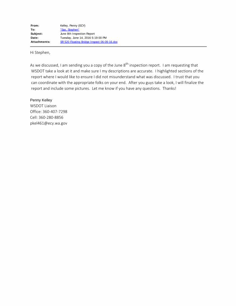
From: Kelley, Penny (ECY)To: "Sax, Stephen"Subject: June 8th Inspection ReportDate: Tuesday, June 14, 2016 5:19:00 PMAttachments: SR 520 Floating Bridge Inspect 06-09-16.doc
Hi Stephen,
As we discussed, I am sending you a copy of the June 8th inspection report. I am requesting that WSDOT take a look at it and make sure I my descriptions are accurate. I highlighted sections of the report where I would like to ensure I did not misunderstand what was discussed. I trust that you can coordinate with the appropriate folks on your end. After you guys take a look, I will finalize the report and include some pictures. Let me know if you have any questions. Thanks! Penny Kelley WSDOT LiaisonOffice: 360-407-7298Cell: [email protected]
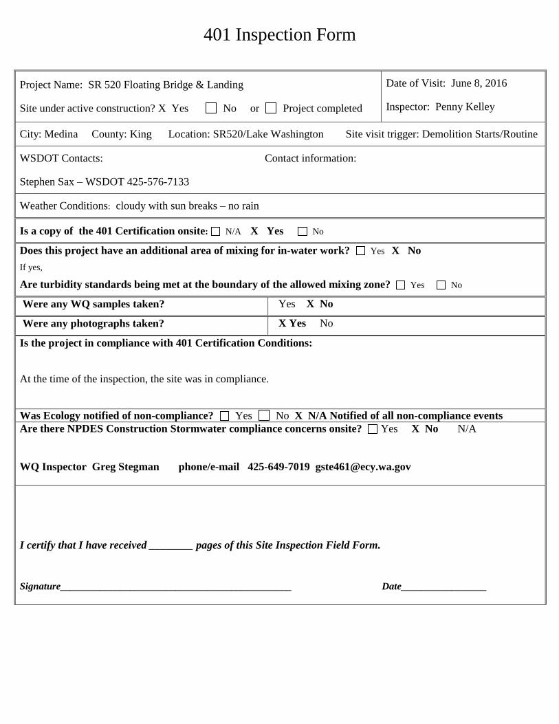
401 Inspection Form
Project Name: SR 520 Floating Bridge & Landing
Site under active construction? X Yes No or Project completed
Date of Visit: June 8, 2016
Inspector: Penny Kelley
City: Medina County: King Location: SR520/Lake Washington Site visit trigger: Demolition Starts/Routine
WSDOT Contacts: Contact information:
Stephen Sax – WSDOT 425-576-7133
Weather Conditions: cloudy with sun breaks – no rain
Is a copy of the 401 Certification onsite: N/A X Yes No
Does this project have an additional area of mixing for in-water work? Yes X No
If yes,
Are turbidity standards being met at the boundary of the allowed mixing zone? Yes No
Were any WQ samples taken? Yes X No
Were any photographs taken? X Yes No
Is the project in compliance with 401 Certification Conditions:
At the time of the inspection, the site was in compliance.
Was Ecology notified of non-compliance? Yes No X N/A Notified of all non-compliance events Are there NPDES Construction Stormwater compliance concerns onsite? Yes X No N/A WQ Inspector Greg Stegman phone/e-mail 425-649-7019 [email protected]
I certify that I have received ________ pages of this Site Inspection Field Form.
Signature______________________________________________ Date_________________
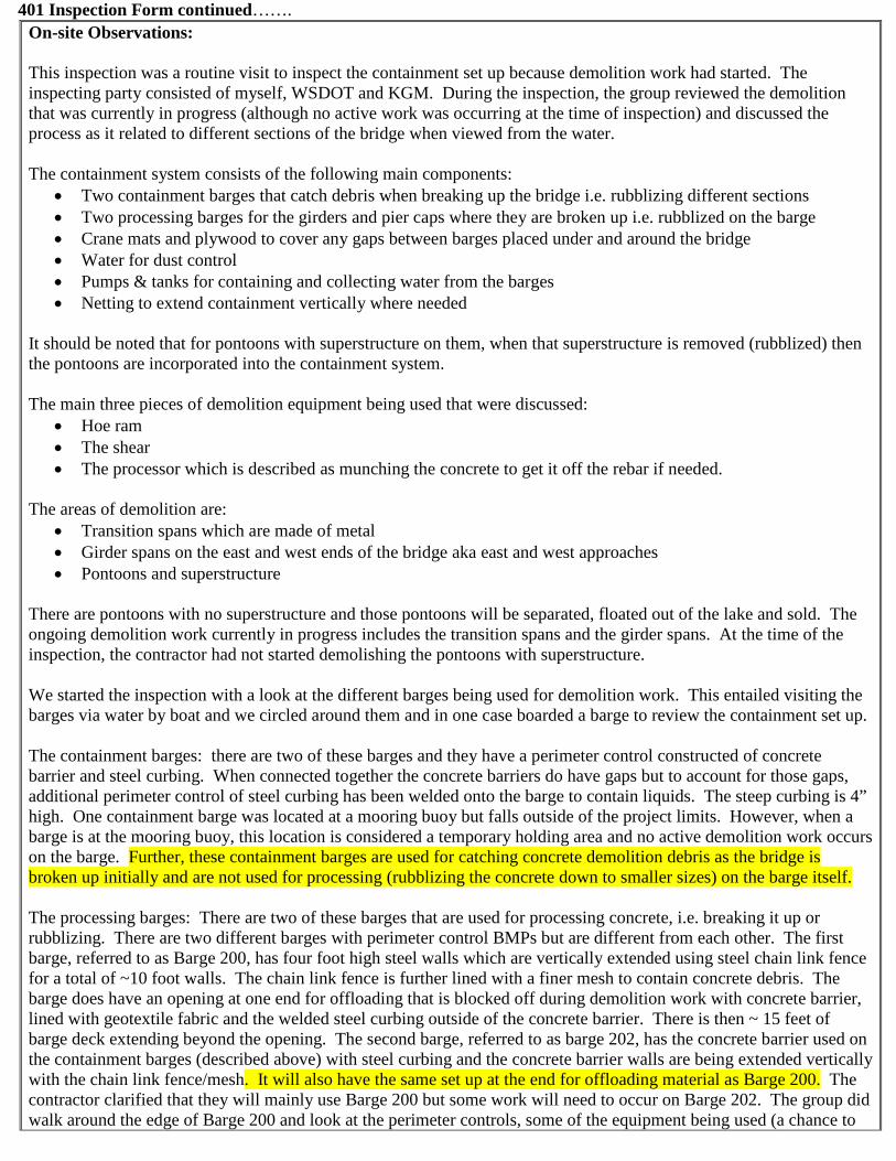
401 Inspection Form continued…….
On-site Observations: This inspection was a routine visit to inspect the containment set up because demolition work had started. The inspecting party consisted of myself, WSDOT and KGM. During the inspection, the group reviewed the demolition that was currently in progress (although no active work was occurring at the time of inspection) and discussed the process as it related to different sections of the bridge when viewed from the water. The containment system consists of the following main components:
• Two containment barges that catch debris when breaking up the bridge i.e. rubblizing different sections • Two processing barges for the girders and pier caps where they are broken up i.e. rubblized on the barge • Crane mats and plywood to cover any gaps between barges placed under and around the bridge • Water for dust control • Pumps & tanks for containing and collecting water from the barges • Netting to extend containment vertically where needed
It should be noted that for pontoons with superstructure on them, when that superstructure is removed (rubblized) then the pontoons are incorporated into the containment system. The main three pieces of demolition equipment being used that were discussed:
• Hoe ram • The shear • The processor which is described as munching the concrete to get it off the rebar if needed.
The areas of demolition are:
• Transition spans which are made of metal • Girder spans on the east and west ends of the bridge aka east and west approaches • Pontoons and superstructure
There are pontoons with no superstructure and those pontoons will be separated, floated out of the lake and sold. The ongoing demolition work currently in progress includes the transition spans and the girder spans. At the time of the inspection, the contractor had not started demolishing the pontoons with superstructure. We started the inspection with a look at the different barges being used for demolition work. This entailed visiting the barges via water by boat and we circled around them and in one case boarded a barge to review the containment set up. The containment barges: there are two of these barges and they have a perimeter control constructed of concrete barrier and steel curbing. When connected together the concrete barriers do have gaps but to account for those gaps, additional perimeter control of steel curbing has been welded onto the barge to contain liquids. The steep curbing is 4” high. One containment barge was located at a mooring buoy but falls outside of the project limits. However, when a barge is at the mooring buoy, this location is considered a temporary holding area and no active demolition work occurs on the barge. Further, these containment barges are used for catching concrete demolition debris as the bridge is broken up initially and are not used for processing (rubblizing the concrete down to smaller sizes) on the barge itself. The processing barges: There are two of these barges that are used for processing concrete, i.e. breaking it up or rubblizing. There are two different barges with perimeter control BMPs but are different from each other. The first barge, referred to as Barge 200, has four foot high steel walls which are vertically extended using steel chain link fence for a total of ~10 foot walls. The chain link fence is further lined with a finer mesh to contain concrete debris. The barge does have an opening at one end for offloading that is blocked off during demolition work with concrete barrier, lined with geotextile fabric and the welded steel curbing outside of the concrete barrier. There is then ~ 15 feet of barge deck extending beyond the opening. The second barge, referred to as barge 202, has the concrete barrier used on the containment barges (described above) with steel curbing and the concrete barrier walls are being extended vertically with the chain link fence/mesh. It will also have the same set up at the end for offloading material as Barge 200. The contractor clarified that they will mainly use Barge 200 but some work will need to occur on Barge 202. The group did walk around the edge of Barge 200 and look at the perimeter controls, some of the equipment being used (a chance to
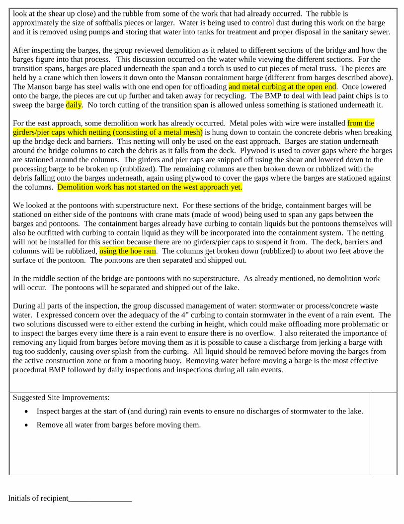
look at the shear up close) and the rubble from some of the work that had already occurred. The rubble is approximately the size of softballs pieces or larger. Water is being used to control dust during this work on the barge and it is removed using pumps and storing that water into tanks for treatment and proper disposal in the sanitary sewer. After inspecting the barges, the group reviewed demolition as it related to different sections of the bridge and how the barges figure into that process. This discussion occurred on the water while viewing the different sections. For the transition spans, barges are placed underneath the span and a torch is used to cut pieces of metal truss. The pieces are held by a crane which then lowers it down onto the Manson containment barge (different from barges described above). The Manson barge has steel walls with one end open for offloading and metal curbing at the open end. Once lowered onto the barge, the pieces are cut up further and taken away for recycling. The BMP to deal with lead paint chips is to sweep the barge daily. No torch cutting of the transition span is allowed unless something is stationed underneath it. For the east approach, some demolition work has already occurred. Metal poles with wire were installed from the girders/pier caps which netting (consisting of a metal mesh) is hung down to contain the concrete debris when breaking up the bridge deck and barriers. This netting will only be used on the east approach. Barges are station underneath around the bridge columns to catch the debris as it falls from the deck. Plywood is used to cover gaps where the barges are stationed around the columns. The girders and pier caps are snipped off using the shear and lowered down to the processing barge to be broken up (rubblized). The remaining columns are then broken down or rubblized with the debris falling onto the barges underneath, again using plywood to cover the gaps where the barges are stationed against the columns. Demolition work has not started on the west approach yet. We looked at the pontoons with superstructure next. For these sections of the bridge, containment barges will be stationed on either side of the pontoons with crane mats (made of wood) being used to span any gaps between the barges and pontoons. The containment barges already have curbing to contain liquids but the pontoons themselves will also be outfitted with curbing to contain liquid as they will be incorporated into the containment system. The netting will not be installed for this section because there are no girders/pier caps to suspend it from. The deck, barriers and columns will be rubblized, using the hoe ram. The columns get broken down (rubblized) to about two feet above the surface of the pontoon. The pontoons are then separated and shipped out. In the middle section of the bridge are pontoons with no superstructure. As already mentioned, no demolition work will occur. The pontoons will be separated and shipped out of the lake. During all parts of the inspection, the group discussed management of water: stormwater or process/concrete waste water. I expressed concern over the adequacy of the 4” curbing to contain stormwater in the event of a rain event. The two solutions discussed were to either extend the curbing in height, which could make offloading more problematic or to inspect the barges every time there is a rain event to ensure there is no overflow. I also reiterated the importance of removing any liquid from barges before moving them as it is possible to cause a discharge from jerking a barge with tug too suddenly, causing over splash from the curbing. All liquid should be removed before moving the barges from the active construction zone or from a mooring buoy. Removing water before moving a barge is the most effective procedural BMP followed by daily inspections and inspections during all rain events. Suggested Site Improvements:
• Inspect barges at the start of (and during) rain events to ensure no discharges of stormwater to the lake.
• Remove all water from barges before moving them.
Initials of recipient________________
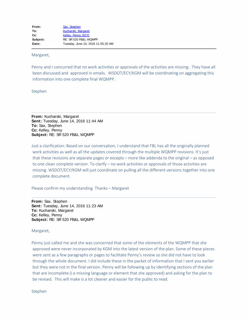
From: Sax, StephenTo: Kucharski, MargaretCc: Kelley, Penny (ECY)Subject: RE: SR 520 FB&L WQMPPDate: Tuesday, June 14, 2016 11:55:20 AM
Margaret, Penny and I concurred that no work activities or approvals of the activities are missing . They have all been discussed and approved in emails. WSDOT/ECY/KGM will be coordinating on aggregating this information into one complete final WQMPP. Stephen
From: Kucharski, Margaret Sent: Tuesday, June 14, 2016 11:44 AMTo: Sax, StephenCc: Kelley, PennySubject: RE: SR 520 FB&L WQMPP Just a clarification: Based on our conversation, I understand that FBL has all the originally planned work activities as well as all the updates covered through the multiple WQMPP revisions. It’s just that these revisions are separate pages or excepts – more like addenda to the original – as opposed to one clean complete version. To clarify – no work activities or approvals of those activities are missing. WSDOT/ECY/KGM will just coordinate on pulling all the different versions together into one complete document. Please confirm my understanding. Thanks – Margaret
From: Sax, Stephen Sent: Tuesday, June 14, 2016 11:23 AMTo: Kucharski, MargaretCc: Kelley, PennySubject: RE: SR 520 FB&L WQMPP Margaret, Penny just called me and she was concerned that some of the elements of the WQMPP that she approved were never incorporated by KGM into the latest version of the plan. Some of these pieces were sent as a few paragraphs or pages to facilitate Penny’s review so she did not have to look through the whole document. I did include these in the packet of information that I sent you earlier but they were not in the final version. Penny will be following up by identifying sections of the plan that are incomplete (i.e missing language or element that she approved) and asking for the plan to be revised. This will make is a lot cleaner and easier for the public to read. Stephen
From: Sax, Stephen Sent: Tuesday, June 14, 2016 9:21 AMTo: Kucharski, Margaret ([email protected])Subject: SR 520 FB&L WQMPP Margaret, Attached are what I believe are all the versions of the WQMPP from 2012 to current. I did not include the most version with the bridge demo activities as these were sent to you yesterday. The updates are a little messy. Rather than rewriting the entire WQMPP they were incorporated into revised sections and submitted to Penny for approval. The process worked well but it makes it a little harder for someone not familiar with the project to follow. Revision 1 – The first version was written on 3/26/2012. There were several amendments made 1 which included Table 1.2 (T 1.2), Attachment 1.2 , Attachment 1.3 and Appendix I pgs. 1-7. Revision 2 – No amendments made Revision 3 – First revision is dated 4/30/2014. Amendments included addition of West Side Staging Area (Update and Monitoring Map) and Floating Coffer Cell. Also I confirmed that the latest version is Revision 4 not 5. Stephen

401 Inspection Form
Project Name: SR 520 Floating Bridge & Landing
Site under active construction? X Yes No or Project completed
Date of Visit: June 8, 2016
Inspector: Penny Kelley
City: Medina County: King Location: SR520/Lake Washington Site visit trigger: Demolition Starts/Routine
WSDOT Contacts: Contact information:
Stephen Sax – WSDOT 425-576-7133
Weather Conditions: cloudy with sun breaks – no rain
Is a copy of the 401 Certification onsite: N/A X Yes No
Does this project have an additional area of mixing for in-water work? Yes X No
If yes,
Are turbidity standards being met at the boundary of the allowed mixing zone? Yes No
Were any WQ samples taken? Yes X No
Were any photographs taken? X Yes No
Is the project in compliance with 401 Certification Conditions:
At the time of the inspection, the site was in compliance.
Was Ecology notified of non-compliance? Yes No X N/A Notified of all non-compliance events Are there NPDES Construction Stormwater compliance concerns onsite? Yes X No N/A WQ Inspector Greg Stegman phone/e-mail 425-649-7019 [email protected]
I certify that I have received ________ pages of this Site Inspection Field Form.
Signature______________________________________________ Date_________________

401 Inspection Form continued…….
On-site Observations: This inspection was a routine visit to inspect the containment set up because demolition work had started. The inspecting party consisted of myself, WSDOT and KGM. During the inspection, the group reviewed the demolition that was currently in progress (although no active work was occurring at the time of inspection) and discussed the process as it related to different sections of the bridge when viewed from the water. The containment system consists of the following main components:
• Two containment barges that catch debris when breaking up the bridge i.e. rubblizing different sections • Two processing barges for the girders and pier caps where they are broken up i.e. rubblized on the barge • Crane mats and plywood to cover any gaps between barges placed under and around the bridge • Water for dust control • Pumps & tanks for containing and collecting water from the barges • Netting to extend containment vertically where needed
It should be noted that for pontoons with superstructure on them, when that superstructure is removed (rubblized) then the pontoons are incorporated into the containment system. The main three pieces of demolition equipment being used that were discussed:
• Hoe ram • The shear • The processor which is described as munching the concrete to get it off the rebar if needed.
The areas of demolition are:
• Transition spans which are made of metal • Girder spans on the east and west ends of the bridge aka east and west approaches • Pontoons and superstructure
There are pontoons with no superstructure and those pontoons will be separated, floated out of the lake and sold. The ongoing demolition work currently in progress includes the transition spans and the girder spans. At the time of the inspection, the contractor had not started demolishing the pontoons with superstructure. We started the inspection with a look at the different barges being used for demolition work. This entailed visiting the barges via water by boat and we circled around them and in one case boarded a barge to review the containment set up. The containment barges: there are two of these barges and they have a perimeter control constructed of concrete barrier and steel curbing. When connected together the concrete barriers do have gaps but to account for those gaps, additional perimeter control of steel curbing has been welded onto the barge to contain liquids. The steep curbing is 4” high. One containment barge was located at a mooring buoy but falls outside of the project limits. However, when a barge is at the mooring buoy, this location is considered a temporary holding area and no active demolition work occurs on the barge. Further, these containment barges are used for catching concrete demolition debris as the bridge is broken up initially and are not used for processing (rubblizing the concrete down to smaller sizes) on the barge itself. The processing barges: There are two of these barges that are used for processing concrete, i.e. breaking it up or rubblizing. There are two different barges with perimeter control BMPs but are different from each other. The first barge, referred to as Barge 200, has four foot high steel walls which are vertically extended using steel chain link fence for a total of ~10 foot walls. The chain link fence is further lined with a finer mesh to contain concrete debris. The barge does have an opening at one end for offloading that is blocked off during demolition work with concrete barrier, lined with geotextile fabric and the welded steel curbing outside of the concrete barrier. There is then ~ 15 feet of barge deck extending beyond the opening. The second barge, referred to as barge 202, has the concrete barrier used on the containment barges (described above) with steel curbing and the concrete barrier walls are being extended vertically with the chain link fence/mesh. It will also have the same set up at the end for offloading material as Barge 200. The contractor clarified that they will mainly use Barge 200 but some work will need to occur on Barge 202. The group did walk around the edge of Barge 200 and look at the perimeter controls, some of the equipment being used (a chance to

look at the shear up close) and the rubble from some of the work that had already occurred. The rubble is approximately the size of softballs pieces or larger. Water is being used to control dust during this work on the barge and it is removed using pumps and storing that water into tanks for treatment and proper disposal in the sanitary sewer. After inspecting the barges, the group reviewed demolition as it related to different sections of the bridge and how the barges figure into that process. This discussion occurred on the water while viewing the different sections. For the transition spans, barges are placed underneath the span and a torch is used to cut pieces of metal truss. The pieces are held by a crane which then lowers it down onto the Manson containment barge (different from barges described above). The Manson barge has steel walls with one end open for offloading and metal curbing at the open end. Once lowered onto the barge, the pieces are cut up further and taken away for recycling. The BMP to deal with lead paint chips is to sweep the barge daily. No torch cutting of the transition span is allowed unless something is stationed underneath it. For the east approach, some demolition work has already occurred. Metal poles with wire were installed from the girders/pier caps which netting (consisting of a metal mesh) is hung down to contain the concrete debris when breaking up the bridge deck and barriers. This netting will only be used on the east approach. Barges are station underneath around the bridge columns to catch the debris as it falls from the deck. Plywood is used to cover gaps where the barges are stationed around the columns. The girders and pier caps are snipped off using the shear and lowered down to the processing barge to be broken up (rubblized). The remaining columns are then broken down or rubblized with the debris falling onto the barges underneath, again using plywood to cover the gaps where the barges are stationed against the columns. Demolition work has not started on the west approach yet. We looked at the pontoons with superstructure next. For these sections of the bridge, containment barges will be stationed on either side of the pontoons with crane mats (made of wood) being used to span any gaps between the barges and pontoons. The containment barges already have curbing to contain liquids but the pontoons themselves will also be outfitted with curbing to contain liquid as they will be incorporated into the containment system. The netting will not be installed for this section because there are no girders/pier caps to suspend it from. The deck, barriers and columns will be rubblized, using the hoe ram. The columns get broken down (rubblized) to about two feet above the surface of the pontoon. The pontoons are then separated and shipped out. In the middle section of the bridge are pontoons with no superstructure. As already mentioned, no demolition work will occur. The pontoons will be separated and shipped out of the lake. During all parts of the inspection, the group discussed management of water: stormwater or process/concrete waste water. I expressed concern over the adequacy of the 4” curbing to contain stormwater in the event of a rain event. The two solutions discussed were to either extend the curbing in height, which could make offloading more problematic or to inspect the barges every time there is a rain event to ensure there is no overflow. I also reiterated the importance of removing any liquid from barges before moving them as it is possible to cause a discharge from jerking a barge with tug too suddenly, causing over splash from the curbing. All liquid should be removed before moving the barges from the active construction zone or from a mooring buoy. Removing water before moving a barge is the most effective procedural BMP followed by daily inspections and inspections during all rain events. Suggested Site Improvements:
• Inspect barges at the start of (and during) rain events to ensure no discharges of stormwater to the lake.
• Remove all water from barges before moving them.
Initials of recipient________________
From: Sax, StephenTo: [email protected]: Bullamore, Bryant; Kelley, Penny (ECY); Kucharski, MargaretSubject: WQMPPDate: Tuesday, June 21, 2016 4:50:30 PM
Robert, We recently were asked to provide an update for the WQMPP. When going through the plan and discussing it with Penny several of the updates were done through email correspondence and were not always incorporated into the latest version of the plan. At this point we need a clean copy of the entire plan with all the approved text changes and work activities incorporated into the plan. This will make it much easier to track all the changes rather than having to find an email approval from 2 or 3 years ago. I have a timeline Penny assembled which should be helpful I this process. She has also identified items that were approved in email with the approximate dates but did not get into the document. Please let me know if you have any questions. Stephen
Stephen J. SaxEnvironmental Compliance Team LeadSR 520, I-5 to Medina: Stage 1 Evergreen Point Floating Bridge and LandingsWashington State Department of Transportation3015 - 112th Ave NE, Suite 100, Bellevue, WA 98004-8001425.576.7133 0ffice 206-713-9783 CellP Please Reduce, Reuse, Recycle, Rethink
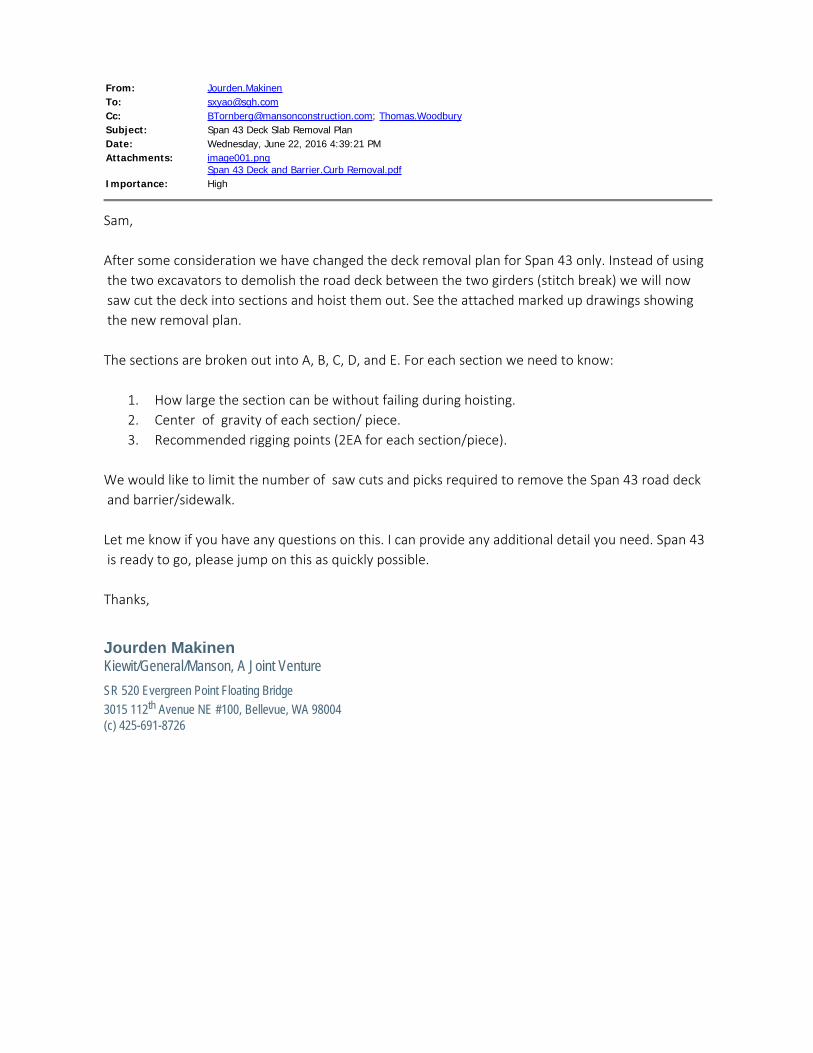
From: Jourden.MakinenTo: [email protected]: [email protected]; Thomas.WoodburySubject: Span 43 Deck Slab Removal PlanDate: Wednesday, June 22, 2016 4:39:21 PMAttachments: image001.png
Span 43 Deck and Barrier.Curb Removal.pdfImportance: High
Sam, After some consideration we have changed the deck removal plan for Span 43 only. Instead of using the two excavators to demolish the road deck between the two girders (stitch break) we will now saw cut the deck into sections and hoist them out. See the attached marked up drawings showing the new removal plan. The sections are broken out into A, B, C, D, and E. For each section we need to know:
1. How large the section can be without failing during hoisting.2. Center of gravity of each section/ piece.3. Recommended rigging points (2EA for each section/piece).
We would like to limit the number of saw cuts and picks required to remove the Span 43 road deck and barrier/sidewalk. Let me know if you have any questions on this. I can provide any additional detail you need. Span 43 is ready to go, please jump on this as quickly possible. Thanks,
Jourden MakinenKiewit/General/Manson, A Joint VentureSR 520 Evergreen Point Floating Bridge3015 112th Avenue NE #100, Bellevue, WA 98004(c) 425-691-8726
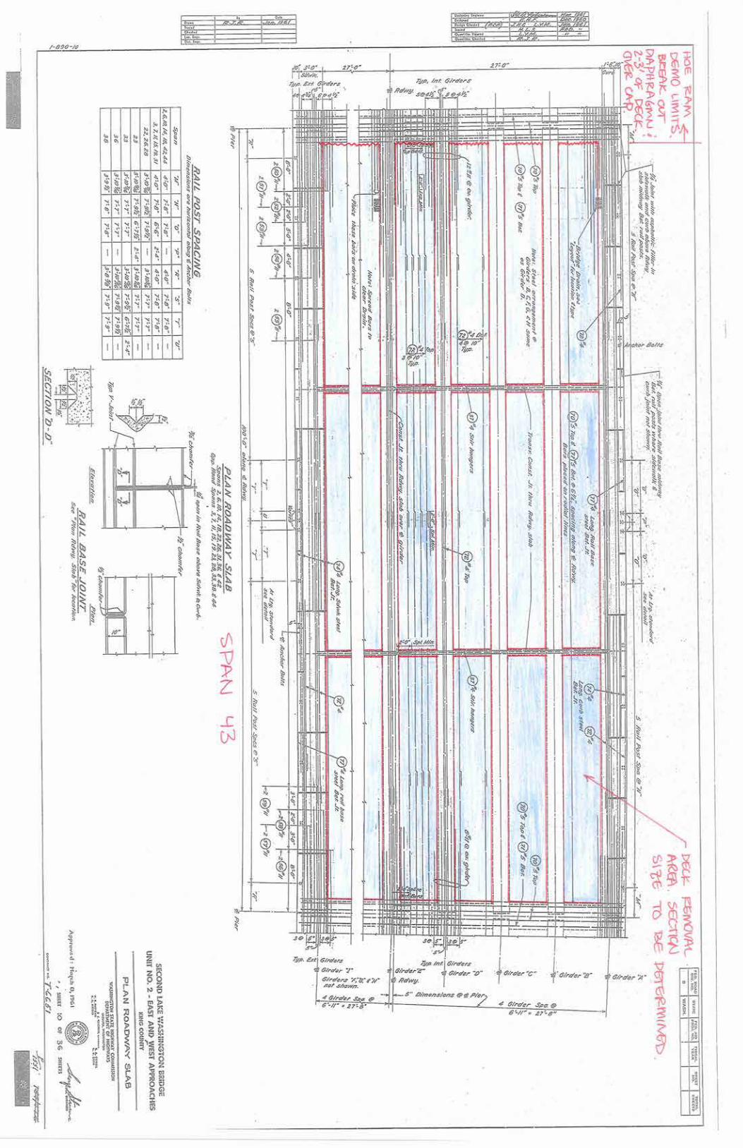
From: [email protected]: [email protected]; [email protected]: Grove Crane outrigger loadingDate: Wednesday, June 22, 2016 5:33:10 PMAttachments: image001.gif
image002.pngRT765E-2-Product-Guide-Imperial.pdfLR Superstructure - Grove Crane Study_rev1.pdf
I believe we still have the 765 still on site but it looks like David looked at the 700. I think that was the other one.
Ben NelsonConstruction Manager | Kiewit/General/Manson, A Joint Venture SR 520 Evergreen Point Floating Bridge3015 112th Avenue N.E. - Suite 100, Bellevue, WA 98004(425) 576-7112 office (925) 864-4127 mobile
Features
•
• full power boom
•
• swingaway extension
•
• to superstructure
Product Guide
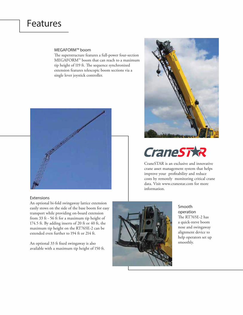
Smooth operation
a quick-reeve boom nose and swingaway alignment device to help operators set up smoothly.
Features
MEGAFORM™ boom
MEGAFORM™ boom that can reach to a maximum
extension features telescopic boom sections via a single lever joystick controller.
ExtensionsAn optional bi-fold swingaway lattice extension easily stows on the side of the base boom for easy transport while providing on-board extension
CraneSTAR is an exclusive and innovative crane asset management system that helps improve your pro�tability and reduce costs by remotely monitoring critical crane data. Visit www.cranestar.com for more information.
Specifications 4
Dimensions and weights 7
Working range 8
Load charts 9
Symbols glossary 10
Contents
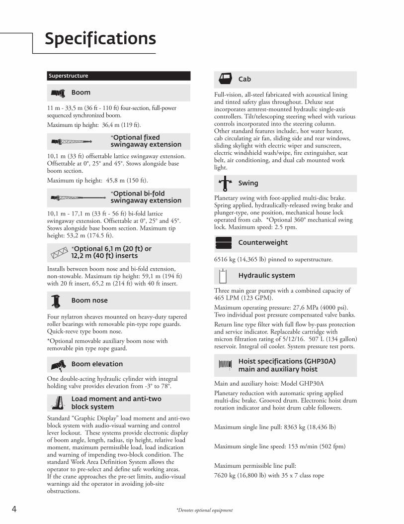
4 *Denotes optional equipment
Specifications
Counterweight
6516 kg (14,365 lb) pinned to superstructure.
Superstructure
Boom
11 m - 33,5 m (36 ft - 110 ft) four-section, full-power sequenced synchronized boom.Maximum tip height: 36,4 m (119 ft).
*Optional fixed swingaway extension
10,1 m (33 ft) offsettable lattice swingaway extension. Offsettable at 0°, 25° and 45°. Stows alongside base boom section. Maximum tip height: 45,8 m (150 ft).
Boom nose
Four nylatron sheaves mounted on heavy-duty tapered roller bearings with removable pin-type rope guards. Quick-reeve type boom nose. *Optional removable auxiliary boom nose with removable pin type rope guard.
Boom elevation
One double-acting hydraulic cylinder with integral holding valve provides elevation from -3° to 78°.
Load moment and anti-two block system
Standard “Graphic Display” load moment and anti-two block system with audio-visual warning and control lever lockout. These systems provide electronic display of boom angle, length, radius, tip height, relative load moment, maximum permissible load, load indication and warning of impending two-block condition. The standard Work Area Definition System allows the operator to pre-select and define safe working areas. If the crane approaches the pre-set limits, audio-visual warnings aid the operator in avoiding job-site obstructions.
Cab
Full-vision, all-steel fabricated with acoustical lining and tinted safety glass throughout. Deluxe seat incorporates armrest-mounted hydraulic single-axis controllers. Tilt/telescoping steering wheel with various controls incorporated into the steering column. Other standard features include:, hot water heater, cab circulating air fan, sliding side and rear windows, sliding skylight with electric wiper and sunscreen, electric windshield wash/wipe, fire extinguisher, seat belt, air conditioning, and dual cab mounted work light.
Swing
Planetary swing with foot-applied multi-disc brake. Spring applied, hydraulically-released swing brake and plunger-type, one position, mechanical house lock operated from cab. *Optional 360° mechanical swing lock. Maximum speed: 2.5 rpm.
Hydraulic system
Three main gear pumps with a combined capacity of 465 LPM (123 GPM).Maximum operating pressure: 27,6 MPa (4000 psi). Two individual post pressure compensated valve banks.Return line type filter with full flow by-pass protection and service indicator. Replaceable cartridge with micron filtration rating of 5/12/16. 507 L (134 gallon) reservoir. Integral oil cooler. System pressure test ports.
*Optional bi-fold swingaway extension
10,1 m - 17,1 m (33 ft - 56 ft) bi-fold lattice swingaway extension. Offsettable at 0°, 25° and 45°. Stows alongside base boom section. Maximum tip height: 53,2 m (174.5 ft).
Hoist specifications (GHP30A) main and auxiliary hoist
Main and auxiliary hoist: Model GHP30APlanetary reduction with automatic spring applied multi-disc brake. Grooved drum. Electronic hoist drum rotation indicator and hoist drum cable followers.
Maximum single line pull: 8363 kg (18,436 lb)
Maximum single line speed: 153 m/min (502 fpm)
Maximum permissible line pull:7620 kg (16,800 lb) with 35 x 7 class rope
*Optional 6,1 m (20 ft) or 12,2 m (40 ft) inserts
Installs between boom nose and bi-fold extension, non-stowable. Maximum tip height: 59,1 m (194 ft) with 20 ft insert, 65,2 m (214 ft) with 40 ft insert.
5Grove RT765E-2 *Denotes optional equipment
Specifications
Carrier
Chassis
Box section frame fabricated from high-strength, low alloy steel. Integral outrigger housings and front/rear towing, lifting, and tie down lugs.
Outrigger system
Four hydraulic telescoping single-stage double box beam outriggers with inverted jacks and integral holding valves. Three position settings, 100%, 50% and fully retracted. All steel fabricated, quick-release type round outrigger floats, 610 mm (24 in) diameter. Maximum outrigger pad load: 41 731 kg (92,000 lb). Outrigger position monitoring system (required for NA/Canada).
Outrigger controls
Controls and crane level indicator located in cab.
Engine (Tier III)
Cummins QSB 6.7 L diesel, six cylinders, turbocharged, 179 kW (240 bhp) (Gross) at 2500 rpm. Maximum torque: 987 N-m (728 ft lb) at 1500 rpm.Note: Required for sale outside of North American and European Union countries
Fuel tank capacity
280 L (74 gal)
Transmission
Spicer powershift with 6 forward and 6 reverse speeds (3 speeds high and 3 speeds low). Front axle disconnect for 4 x 2 travel.
Electrical system
Three 12-volt maintenance free batteries. 12-volt starting and lighting, circuit breakers, battery disconnect switch.
Steering
Fully independent power steering:Front: Full hydraulic, steering wheel controlled.Rear: Full hydraulic, switch controlled.Provides infinite variations of 4 main steering modes: front only, rear only, crab and coordinated. Rear steer centered indicating light.4 wheel outside turning radius - 7,1 m (23 ft 4 in).
Axles
Front: Drive/steer with differential and planetary reduction hubs rigid-mounted to frame.Rear: Drive/steer with differential and planetary reduction hubs pivot-mounted to frame. Automatic full hydraulic lockouts on rear axle permit 203 mm (8 in) oscillation only with boom centered over the front.
4 x 4
Drive
Rope diameter: 19 mm (3/4 in)
Rope length: 152 m (500 ft) Rope type: 35x7 class rotation resistant
Maximum rope stowage: 212 m (695 ft).
Superstructure continued
Engine (Tier IV)
Cummins QSB 6.7 L diesel, six cylinders, turbocharged with Cummins Diesel Particulate Exhaust filter/muffler. Meets emissions per U.S.E.P.A. Tier IV and E.U. Stage III B. 179 kW (240 bhp) at 2500 rpm. Maximum torque: 987 N-m (728 ft lb) at 1500 rpm.Fuel requirement: Maximum of 15 ppm sulphur content (Ultra Low Diesel Fuel). Note: Tier IV engine Required in North American and European Union countries.
6
Specifications
Full width steel fenders, full length steel decking, dual rear view mirrors, hook block tiedown, electronic back-up alarm, light package, front stowage well, tachometer, rear wheel position indicator, 36,000 BTU hot water heater, air conditioning package with 28,500 BTU hydraulic driven air conditioning, hoist mirrors, engine distress A/V warning system. Auxiliary hoist control valve arrangement (less hoist). Cold start aid and immersion type engine block heater, 120V 1500 watt. Hoist access platform, CraneSTAR asset management system, Outrigger position monitoring system.
Miscellaneous standard equipment
130% (Based on 42 388 kg [93,447 lb] GVW) 29.5 x 25 tires, pumps engaged, 33,6 m (110 ft) boom, bi-fold extension, aux. hoist and cable, and 65 USt hook block.
Gradeability (theoretical)
Carrier continued
*Denotes optional equipment
Full lighting package including turn indicators, head, tail, brake and hazard warning lights.
Lights
37 km/h (23 mph) (no load).
Maximum speed
Auxiliary Hoist Package (includes Model GHP30A) auxiliary hoist with electronic hoist drum rotation indicator, hoist drum cable follower, 152 m (500 ft) of 19 mm (3/4 in) 35 X 7 class wire rope, auxiliary single sheave boom nose.Auxiliary Light and Convenience Package: includes superstructure mounted amber flashing light, in-cab LMI light bar, and dual base boom mounted floodlights, rubber mat for stowage trough“CE” Mark Conformance (sound abatement foam kits, 3rd wrap indicator, emergency auxiliary steering, dual axis joystick controllers)Cross axle differential locks (front and rear) Manual pump disconnectPintle hook - rear360⁰ NYC style positive swinglockPAT event recorderHydraulic removable counterweight3rd wrap indicator with function lockout for main hoist or main and auxiliary hoistWireless windspeed indicator-29° C (-20° F) cold weather package
*Optional equipment
Full hydraulic split circuit brakes operating on all wheels. Spring-applied, hydraulically released axle-mounted parking brake.
Brakes
29.5 x 25 - 28PR bias earthmover type.
Tires
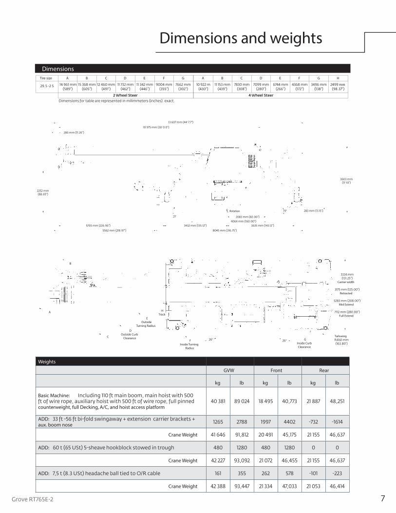
Dimensions and weights
Weights
GVW Front Rear
kg lb kg lb kg lb
Basic Machine:
counterweight, full Decking, A/C, and hoist access platform
ADD:aux. boom nose
Crane Weight
ADD:
Crane Weight
ADD:
Crane Weight
Dimensions
'
'
'
°
°
RotationCL
Tire size A B C D E F G A B C D E F G H
mm
Carrier width
Retracted
Mid Extend
Full Extend
FInside Turning
Radius
EOutside
Turning Radius
DOutside Curb
ClearanceC
A
B
°° GInside Curb Clearance
Tailswing
HTrack
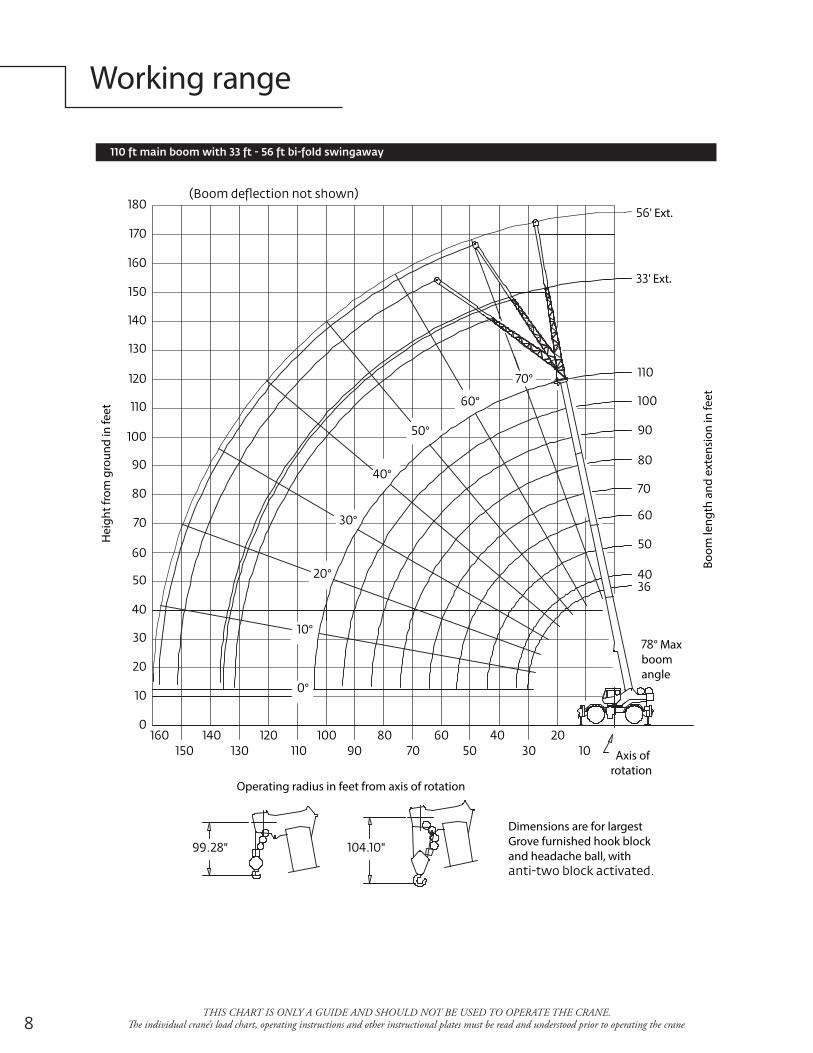
Working range
THIS CHART IS ONLY A GUIDE AND SHOULD NOT BE USED TO OPERATE THE CRANE. �e individual crane’s load chart, operating instructions and other instructional plates must be read and understood prior to operating the crane
Hei
ght f
rom
gro
und
in fe
et
Operating radius in feet from axis of rotation
Boom
leng
th a
nd e
xten
sion
in fe
et
Axis of rotation
Dimensions are for largest Grove furnished hook block and headache ball, with
" "
° Max boom angle
°
°
°
°
°
°
°
°
' Ext.
' Ext.
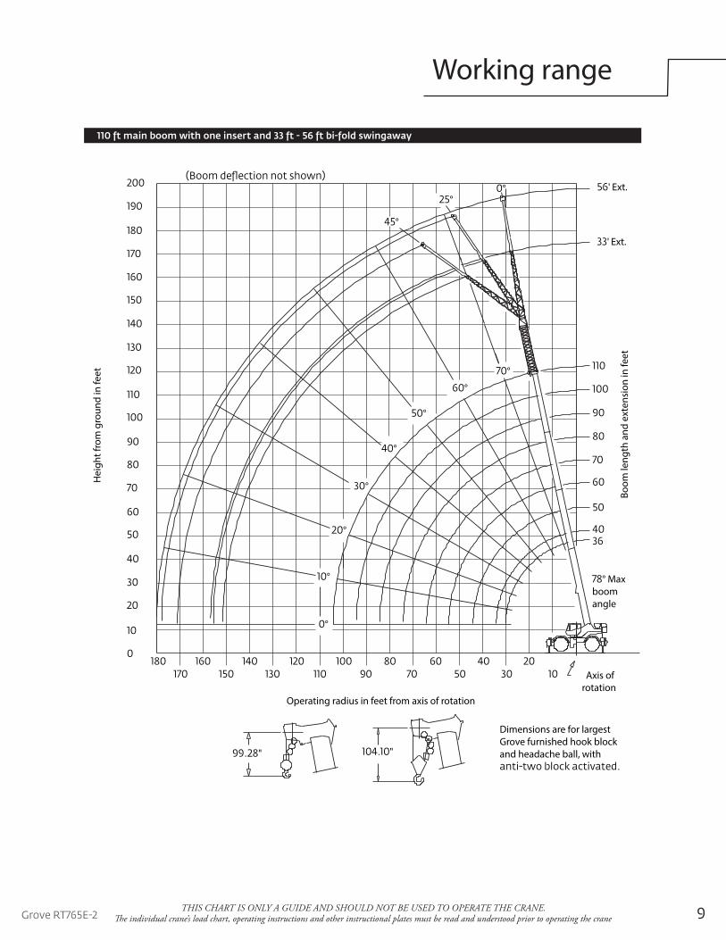
Working range
THIS CHART IS ONLY A GUIDE AND SHOULD NOT BE USED TO OPERATE THE CRANE. �e individual crane’s load chart, operating instructions and other instructional plates must be read and understood prior to operating the crane
Hei
ght f
rom
gro
und
in fe
et
Operating radius in feet from axis of rotation
Boom
leng
th a
nd e
xten
sion
in fe
et
Axis of rotation
Dimensions are for largest Grove furnished hook block and headache ball, with " "
° Max boom angle
' Ext.
' Ext.
°
°
°
°
°
°
°
°
°
°°
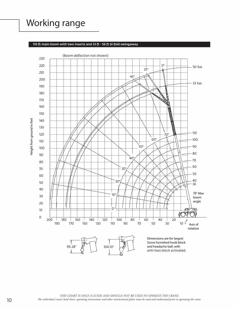
Working rangeH
eigh
t fro
m g
roun
d in
feet
Dimensions are for largest Grove furnished hook block and headache ball, with " "
° Max boom angle
' Ext.
' Ext.
Axis of rotation
°°
°
°
°
°
°
°
°°
°
THIS CHART IS ONLY A GUIDE AND SHOULD NOT BE USED TO OPERATE THE CRANE. �e individual crane’s load chart, operating instructions and other instructional plates must be read and understood prior to operating the crane

Load chart
THIS CHART IS ONLY A GUIDE AND SHOULD NOT BE USED TO OPERATE THE CRANE. �e individual crane’s load chart, operating instructions and other instructional plates must be read and understood prior to operating the crane
R a diusin
feetM a in boom length in fe et
., ,
.* ,
,.
, , ,.
* ,
, , ,.
,.
, * ,
,.
, , , , ,.
, *
,.
, , , , ,.
, , * ,
, , ,.
,.
, ,.
,.
, ,
, ,.
, ,.
, , ,.
, ,.
, ,.
,.
, ,.
,.
, , , ,.
,.
,.
, ,.
, ,.
,.
, , , , ,
, ,.
,.
,.
,.
,.
,.
,.
,.
., ,
. .
. .
.
.
daol on htgnel detacidni rof ° elgna moob muminiM
daol on elgna moob ° ta tf htgnel moob mumixaMNO TE : B oom angles a re in degrees.
LMI opera ting code . R efer to LMI manual for opera ting instructions.*This cap a city is ba sed on maximum boom angle.
Lift ing ca pa cit ies a t zero de gree boom ang le
Bo oma ngle
M a in boom length in fe et
**
°,
., ,
.,
.,
. . . .NO TE : R eference ra dii in feet.** B oo m length is w ith inne mid fully extended a nd outer mid & fly fully retracted.
OutriggersCounterweight
°
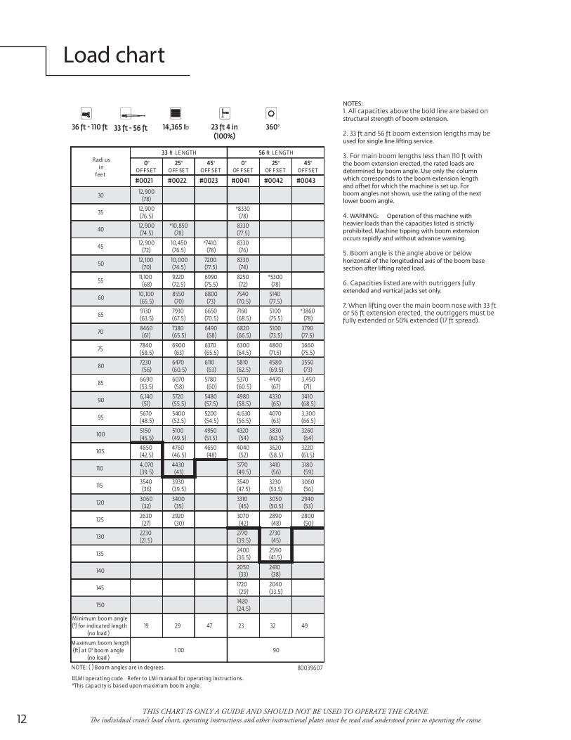
Load chart
THIS CHART IS ONLY A GUIDE AND SHOULD NOT BE USED TO OPERATE THE CRANE. �e individual crane’s load chart, operating instructions and other instructional plates must be read and understood prior to operating the crane
O N O U TR IGG ERS FUL LY EX TENDED °
R adi usin
fee t
HTGNEL tf HTGNEL tf
°O F FS E T
°O FF SE T
°O FF SE T
°OF F SE T
°OF F SE T
°O FF S E T
,
,.
*
,.
* ,.
, ,.
*
, ,. .
,. .
*
,. . .
. . . . .*
. . . .
. . . . .
. . .
. .,
,. . . .
. . .,
.,
.
. . . .
. . . .
,. .
. . .
.
. .
. .
.
.
M inimum boo m angle for indicated length
no load
M axim um boo m lengthft at ° boo m angle
no load
N OTE: B oo m angles are in degrees.
M I operating code . R efer to LM I m anual for operating instructions.*This cap acity is ba sed upon maximum boo m angle.
OutriggersCounterweight
lb °
NOTES:
structural strength of boom extension.
used for single line lifting service.
the boom extension erected, the rated loads are determined by boom angle. Use only the column which corresponds to the boom extension length and o�set for which the machine is set up. For boom angles not shown, use the rating of the next lower boom angle.
WARNING: Operation of this machine with heavier loads than the capacities listed is strictly prohibited. Machine tipping with boom extension occurs rapidly and without advance warning.
horizontal of the longitudinal axis of the boom base section after lifting rated load.
extended and vertical jacks set only.
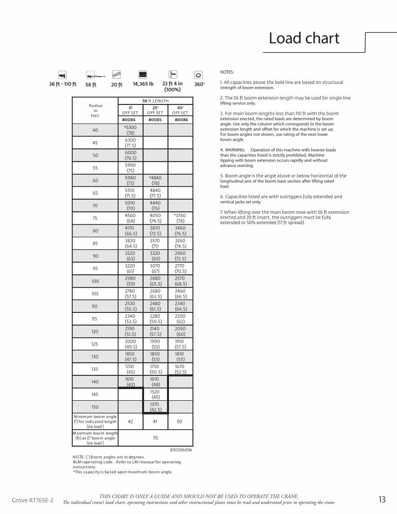
Load chart
THIS CHART IS ONLY A GUIDE AND SHOULD NOT BE USED TO OPERATE THE CRANE. �e individual crane’s load chart, operating instructions and other instructional plates must be read and understood prior to operating the crane
NOTES:
strength of boom extension.
lifting service only.
extension erected, the rated loads are determined by boom angle. Use only the column which corresponds to the boom extension length and o�set for which the machine is set up. For boom angles not shown, use rating of the next lower boom angle.
WARNING: Operation of this machine with heavier loads than the capacities listed is strictly prohibited. Machine tipping with boom extension occurs rapidly and without advance warning.
longitudinal axis of the boom base section after lifting rated load.
vertical jacks set only.
R a diusin
fee t
ft LE NGTH
°O FF S ET
°O FF SE T
°O FF SE T
*
.
.
*
. .
.*
. . .
. .
.
.
. .
. . .
. . .
. .
. .
. .
.
. .
.M inim um boo m angle
for indicated lengthno load
M aximum boo m lengthft at ° boo m angle
no load
A
NO TE: B oo m angles are in deg rees.M I ope rating code . Refer to LM I manua l for operating
instructions.*This ca pa city is ba sed upon maxim um boom angle.
OutriggersCounterweight
°
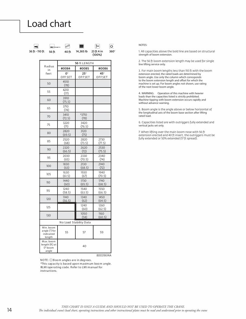
Load chart
THIS CHART IS ONLY A GUIDE AND SHOULD NOT BE USED TO OPERATE THE CRANE. �e individual crane’s load chart, operating instructions and other instructional plates must be read and understood prior to operating the crane
NOTES:
strength of boom extension.
line lifting service only.
extension erected, the rated loads are determined by boom angle. Use only the column which corresponds to the boom extension length and o�set for which the machine is set up. For boom angles not shown, use rating of the next lower boom angle.
WARNING: Operation of this machine with heavier loads than the capacities listed is strictly prohibited. Machine tipping with boom extension occurs rapidly and without advance warning.
the longitudinal axis of the boom base section after lifting rated load.
vertical jacks set only.
ON OUT R IGG ERS F UL LY EX T ENDED - 360 °
R a diusin
fee t
ft LE NGTH
°O FF S E T
°O F F SE T
°O F F SE T
.
.*
.
.
. .
. .
.
.
. .
. .
. . .
. .
.
.
N o Load Stability D ata
M in. booma ngle ° for
indicatedlength
M ax. boo mlength f a t
° boomangle
A
NO TE : B oo m angles are in deg rees .*This cap acity is based upon maxim um boo m angle.
LM I ope rating code. R efer to LM I m anual forinstructions.
OutriggersCounterweight
°
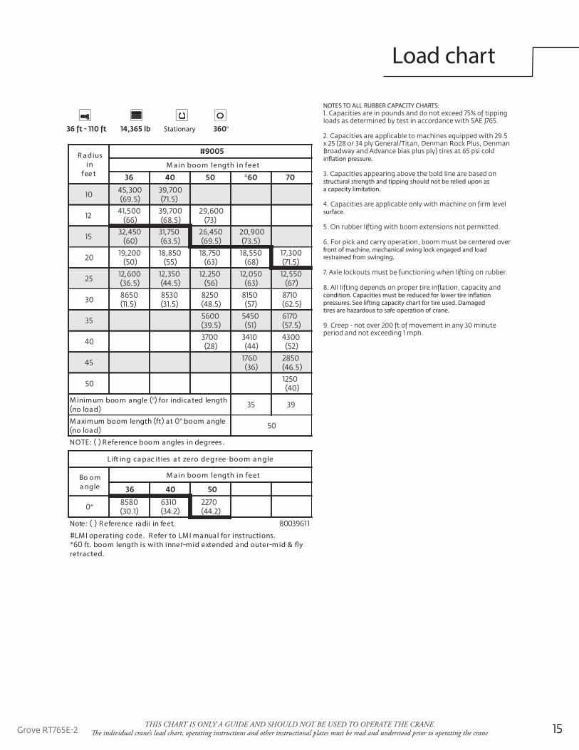
Load chart
THIS CHART IS ONLY A GUIDE AND SHOULD NOT BE USED TO OPERATE THE CRANE. �e individual crane’s load chart, operating instructions and other instructional plates must be read and understood prior to operating the crane
NOTES TO ALL RUBBER CAPACITY CHARTS:
in�ation pressure.
structural strength and tipping should not be relied upon as a capacity limitation.
surface.
front of machine, mechanical swing lock engaged and load restrained from swinging.
condition. Capacities must be reduced for lower tire in�ation pressures. See lifting capacity chart for tire used. Damaged tires are hazardous to safe operation of crane.
STATIONARY CAPACITIES
R a diusin
fee tM a in boo m length in feet
,.
,.
, ,.
,
, ,.
,.
,.
, , , , ,.
,.
,.
, , ,
. . . .
. .
.
M inim um boo m angle ° for indica ted lengthno loa d
M aximum boom length ft at ° boom angleno loa d
NOTE : R eference boo m angles in degrees .
Lift ing ca pac ities a t zero degree boo m an gle
Bo oma ngle
M a in boo m length in feet
° . . .
.teef ni iidar ecnerefeR :etoN
LM I operating code. R efer to LM I ma nual for instructions.* ft. boom length is with inne mid extended a nd outer m id & flyretracted.
Counterweight
°Stationary
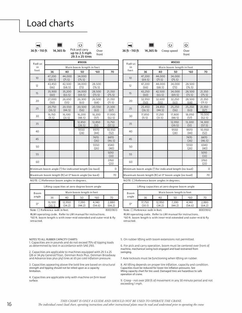
Load charts
THIS CHART IS ONLY A GUIDE AND SHOULD NOT BE USED TO OPERATE THE CRANE. �e individual crane’s load chart, operating instructions and other instructional plates must be read and understood prior to operating the crane
R adi usin
feetM a in boo m le ngth in fee t
*
,.
,.
,.
, ,.
, ,.
, ,.
,.
,.
,.
, , , , ,.
,.
,.
, , ,
,.
,.
,.
, ,.
,.
, ,.
,
.
M inimum boo m angle ° for indicated length no loa d
M aximum boom length ft a t ° boo m angle no loa d
NO TE : R eference boom angles in degrees.
Lift ing capac ities at zero degree boom angle
B ooma ngle
M ain boo m length in feet
*
°,
.,
.,
.,
.,
.
.teef ni iidar ecnerefeR :etoN
LM I operating co de. R efer to LM I manual for instructions.* ft . boo m length is w ith inner mid extended a nd outer mid & flyretracted.
R adi usin
fee tM a in boom length in f eet
*
,.
,.
,.
, ,.
, ,.
, ,.
,.
,.
,.
, , , , ,.
,.
,.
, , ,
,.
,.
,.
, ,.
,.
, ,.
,
.
M inimum boo m angle ° for indic ated length no load
M aximum boom length ft a t ° boom angle no load
NO TE : R eference boom a ngles in degrees.
Lifting capacities at zero degree boo m angle
B ooma ngle
M ain boom length in feet
*
°,
.,
.,
.,
.,
.
.teef ni iidar ecnerefeR :etoN
M I operating code. R efer to LM I manual for instructions.* ft . boom length is with inne mid extended and outer mid & flyretracted.
Counterweight
Overfront
Pick and carry
Counterweight
Overfront
Creep speed
NOTES TO ALL RUBBER CAPACITY CHARTS:
strength and tipping should not be relied upon as a capacity limitation.
surface.
machine, mechanical swing lock engaged and load restrained from swinging.
Capacities must be reduced for lower tire in�ation pressures. See lifting capacity chart for tire used. Damaged tires are hazardous to safe operation of crane.
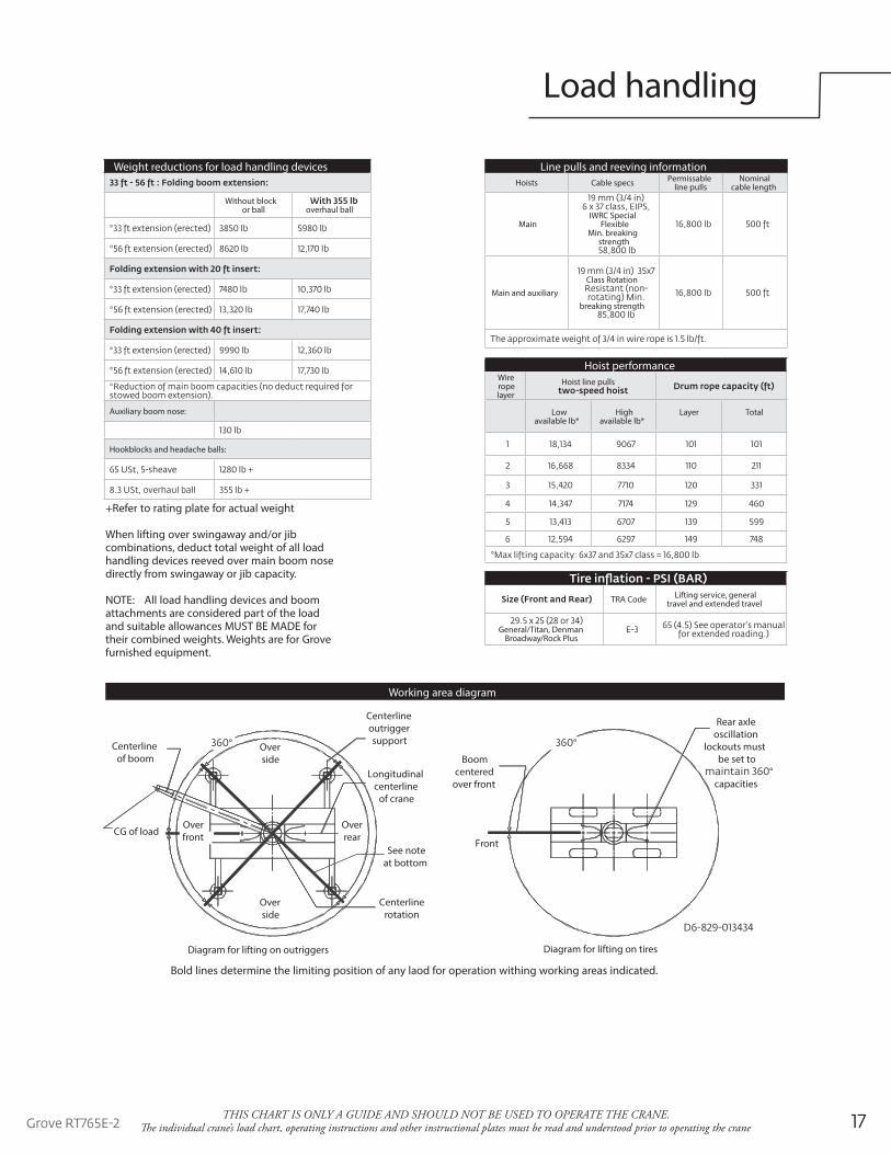
Load handling
THIS CHART IS ONLY A GUIDE AND SHOULD NOT BE USED TO OPERATE THE CRANE. �e individual crane’s load chart, operating instructions and other instructional plates must be read and understood prior to operating the crane
+Refer to rating plate for actual weight
When lifting over swingaway and/or jib combinations, deduct total weight of all load handling devices reeved over main boom nose directly from swingaway or jib capacity.
NOTE: All load handling devices and boom attachments are considered part of the load and suitable allowances MUST BE MADE for their combined weights. Weights are for Grove furnished equipment.
Hoist performanceWire rope layer
Hoist line pulls
Lowavailable lb*
Highavailable lb*
Layer Total
Line pulls and reeving informationHoists Cable specs Permissable
line pullsNominal
cable length
MainIWRC Special
Flexible Min. breaking
strength
Main and auxiliaryClass Rotation
breaking strength
Weight reductions for load handling devices
Without block or ball overhaul ball
Auxiliary boom nose:
Hookblocks and headache balls:
TRA Code Lifting service, general travel and extended travel
General/Titan, Denman Broadway/Rock Plus
Working area diagram
Over rear
Centerline of boom
CG of loadOver front
Over side
Over side
°
Centerline outrigger support
Longitudinal centerline
of crane
See noteat bottom
Centerline rotation
°
Rear axle oscillation
lockouts must be set to
° capacities
Front
Boom centered
over front
Diagram for lifting on tiresDiagram for lifting on outriggers
Bold lines determine the limiting position of any laod for operation withing working areas indicated.
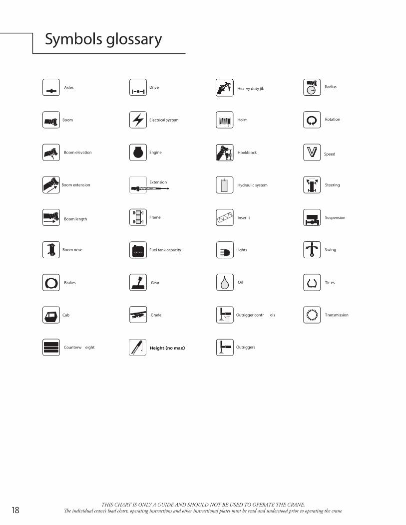
Symbols glossary
THIS CHART IS ONLY A GUIDE AND SHOULD NOT BE USED TO OPERATE THE CRANE. �e individual crane’s load chart, operating instructions and other instructional plates must be read and understood prior to operating the crane
Drive
RotationElectrical system
Suspension
Fuel tank capacity
Tir es
Engine
Brakes
Outrigger contr ols
Axles
Outriggers
Transmission
Frame
Steering
Lights
Boom elevation
Cab
Swing
Hydraulic system
Inser t
Hoist
Boom nose
Radius
Boom extension
Boom length
Grade
Gear
Boom
Counterw eight
Speed
Oil
Extension
HookblockH
Hea vy duty jib

19Grove RT765E-2
Notes
THIS CHART IS ONLY A GUIDE AND SHOULD NOT BE USED TO OPERATE THE CRANE. The individual crane’s load chart, operating instructions and other instructional plates must be read and understood prior to operating the crane

©2011 ManitowocForm No.RT765E-2 PGPart No.10-009-2M-0911 www.manitowoc.com
This document is non-contractual. Constant improvement and engineering progress make it necessary that we reserve the right to make specification, equipment, and price changes without notice. Illustrations shown may include optional equipment and accessories and may not include all standard equipment.
Regional offices
ChinaShanghai, China Tel: +86 21 6457 0066Fax: +86 21 6457 4955
Greater Asia-Pacific Singapore Tel: +65 6264 1188 Fax: +65 6862 4040
Europe, Middle East, Africa Ecully, France Tel: +33 (0)4 72 18 20 20 Fax: +33 (0)4 72 18 20 00
Americas Manitowoc, Wisconsin, USA Tel: +1 920 684 6621 Fax: +1 920 683 6277
Shady Grove, Pennsylvania, USA Tel: +1 717 597 8121 Fax: +1 717 597 4062
Regional headquarters
Manitowoc Cranes
ChinaBeijingChengduGuangzhouXian
Greater Asia-PacificAustraliaAdelaideBrisbaneMelbourneSydneyIndiaCalcuttaChennaiDelhiHyderabadPuneKoreaSeoulPhilippinesMakati CitySingapore
FactoriesBrazilAlphavilleChinaTaiAnZhangjiagangFranceCharlieuMoulinsGermanyWilhelmshavenIndiaPuneItalyNiella TanaroPortugalBaltarFânzeresSlovakiaSarisUSAManitowoc Port WashingtonShady Grove
AmericasBrazilAlphavilleMexicoMonterreyChileSantiago
Europe, Middle East, AfricaCzech RepublicNetvoriceFranceBaudemontCergyDecinesGermanyLangenfeldHungaryBudapestItalyLainateNetherlandsBredaPolandWarsawPortugalBaltarRussiaMoscowU.A.E.DubaiU.K.Buckingham
SR 520 I-5 to Medina Floating Bridge Low Rise Superstructure – Grove Crane RT700E on Deck
Prepared by David Birrcher Checked by Daniel Tassin Revision 1 (Note: Revisions noted with underline) March 10, 2015
SR 520 Floating Bridge Low Rise Superstructure - Grove Crane RT700E on Deck
Table of Contents Executive Summary ......................................................................................................................................................... 3
Introduction .................................................................................................................................................................... 4
Grove Crane Weight on Deck Analysis ............................................................................................................................ 5
Crane Loads ................................................................................................................................................................. 5
Analysis Model ............................................................................................................................................................ 8
Capacity Evaluation ................................................................................................................................................... 10
Appendix ....................................................................................................................................................................... 24
International Bridge Technologies, Inc. 2
SR 520 Floating Bridge Low Rise Superstructure - Grove Crane RT700E on Deck
Executive Summary
This report documents analysis of the low rise superstructure using loads provided by KGM. IBT does not take responsibility for the accuracy of the loads. In addition, the operation of construction equipment from which the loads were derived shall follow the appropriate recommendations of the supplier or governing standard.
Based on the findings described in this report, we have no objections to subjecting the low rise superstructure to the loadings described herein subject to the following restrictions:
1. The crane shall not be placed on the low-rise superstructure until the permanent post-tensioning has been stressed and the bearings have been grouted. The tendons do not have to be grouted. The falsework shall be removed.
2. The crane may be placed on the superstructure prior to the installation of the expansion joint shear key beams.
3. The location of the crane shall be limited to the areas shown in Figures 5 and 6.
4. The maximum lift load permitted by the crane is 80 kips. This load shall only be lifted in accordance with the crane supplier lift chart.
5. The outrigger reactions shall be spread longitudinally to (2) deck supports as shown schematically in Figure 4. Each bearing area on the deck shall be a minimum of 12” x 12.” The deck supports shall not be located closer than 3’-0” to a segment joint.
6. An HS20 truck may be placed on the deck at the same time as the crane. There are no restrictions on the placement of the truck.
International Bridge Technologies, Inc. 3
SR 520 Floating Bridge Low Rise Superstructure - Grove Crane RT700E on Deck
Introduction
KGM has requested to place a Grove RT700E crane on the completed deck of the Low Rise superstructure. The purpose of the crane is to service the fabrication of the steel Transition span girders being performed on the north side of the completed deck. The crane will operate on the south side of the completed deck. The weight of the crane including maximum considered lift loads was provided by KGM (see appendix). An analysis of the low rise superstructure was performed to determine the demand on the superstructure members. The capacity of the superstructure members was compared to the demand. The analysis and capacity evaluation is summarized in this report.
International Bridge Technologies, Inc. 4
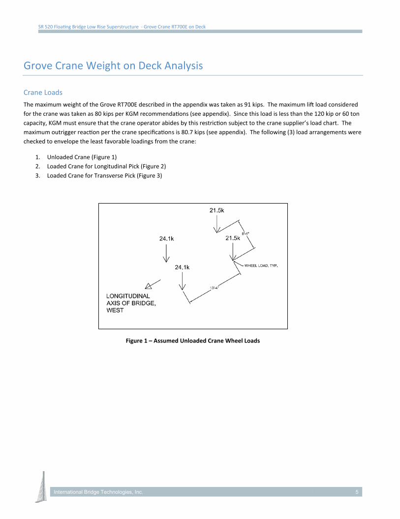
SR 520 Floating Bridge Low Rise Superstructure - Grove Crane RT700E on Deck
Grove Crane Weight on Deck Analysis
Crane Loads The maximum weight of the Grove RT700E described in the appendix was taken as 91 kips. The maximum lift load considered for the crane was taken as 80 kips per KGM recommendations (see appendix). Since this load is less than the 120 kip or 60 ton capacity, KGM must ensure that the crane operator abides by this restriction subject to the crane supplier’s load chart. The maximum outrigger reaction per the crane specifications is 80.7 kips (see appendix). The following (3) load arrangements were checked to envelope the least favorable loadings from the crane:
1. Unloaded Crane (Figure 1) 2. Loaded Crane for Longitudinal Pick (Figure 2) 3. Loaded Crane for Transverse Pick (Figure 3)
Figure 1 – Assumed Unloaded Crane Wheel Loads
International Bridge Technologies, Inc. 5
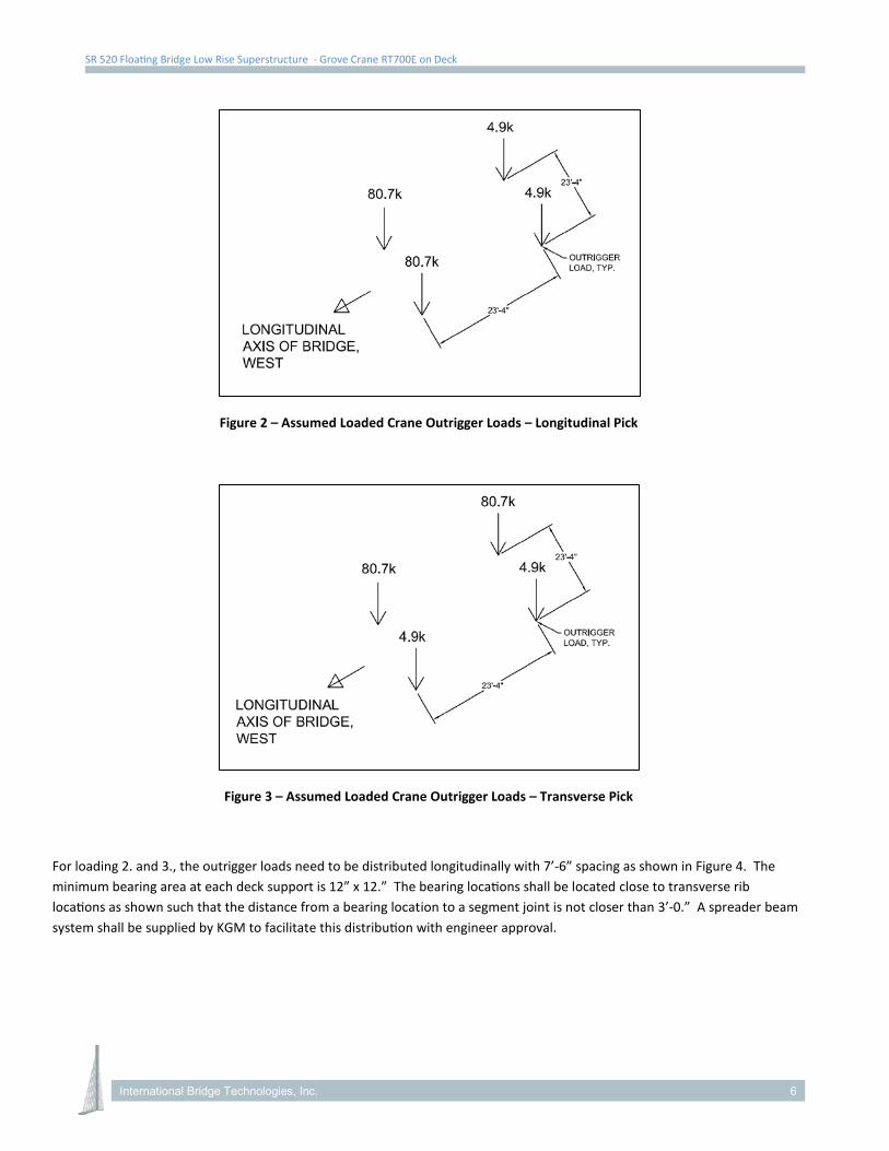
SR 520 Floating Bridge Low Rise Superstructure - Grove Crane RT700E on Deck
Figure 2 – Assumed Loaded Crane Outrigger Loads – Longitudinal Pick
Figure 3 – Assumed Loaded Crane Outrigger Loads – Transverse Pick
For loading 2. and 3., the outrigger loads need to be distributed longitudinally with 7’-6” spacing as shown in Figure 4. The minimum bearing area at each deck support is 12” x 12.” The bearing locations shall be located close to transverse rib locations as shown such that the distance from a bearing location to a segment joint is not closer than 3’-0.” A spreader beam system shall be supplied by KGM to facilitate this distribution with engineer approval.
International Bridge Technologies, Inc. 6
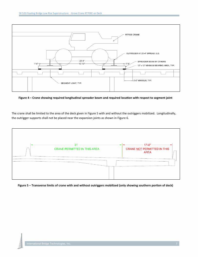
SR 520 Floating Bridge Low Rise Superstructure - Grove Crane RT700E on Deck
Figure 4 – Crane showing required longitudinal spreader beam and required location with respect to segment joint
The crane shall be limited to the area of the deck given in Figure 5 with and without the outriggers mobilized. Longitudinally, the outrigger supports shall not be placed near the expansion joints as shown in Figure 6.
Figure 5 – Transverse limits of crane with and without outriggers mobilized (only showing southern portion of deck)
International Bridge Technologies, Inc. 7
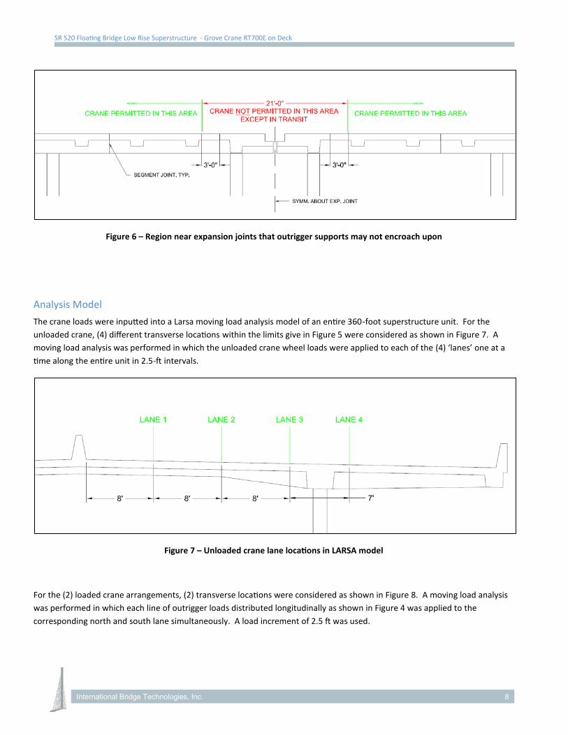
SR 520 Floating Bridge Low Rise Superstructure - Grove Crane RT700E on Deck
Figure 6 – Region near expansion joints that outrigger supports may not encroach upon
Analysis Model The crane loads were inputted into a Larsa moving load analysis model of an entire 360-foot superstructure unit. For the unloaded crane, (4) different transverse locations within the limits give in Figure 5 were considered as shown in Figure 7. A moving load analysis was performed in which the unloaded crane wheel loads were applied to each of the (4) ‘lanes’ one at a time along the entire unit in 2.5-ft intervals.
Figure 7 – Unloaded crane lane locations in LARSA model
For the (2) loaded crane arrangements, (2) transverse locations were considered as shown in Figure 8. A moving load analysis was performed in which each line of outrigger loads distributed longitudinally as shown in Figure 4 was applied to the corresponding north and south lane simultaneously. A load increment of 2.5 ft was used.
International Bridge Technologies, Inc. 8
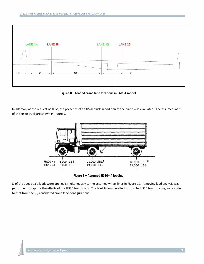
SR 520 Floating Bridge Low Rise Superstructure - Grove Crane RT700E on Deck
Figure 8 – Loaded crane lane locations in LARSA model
In addition, at the request of KGM, the presence of an HS20 truck in addition to the crane was evaluated. The assumed loads of the HS20 truck are shown in Figure 9.
Figure 9 – Assumed HS20-44 loading
½ of the above axle loads were applied simultaneously to the assumed wheel lines in Figure 10. A moving load analysis was performed to capture the effects of the HS20 truck loads. The least favorable effects from the HS20 truck loading were added to that from the (3) considered crane load configurations.
International Bridge Technologies, Inc. 9
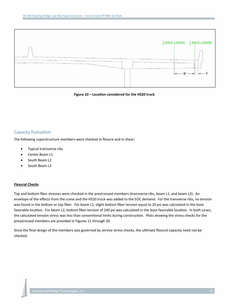
SR 520 Floating Bridge Low Rise Superstructure - Grove Crane RT700E on Deck
Figure 10 – Location considered for the HS20 truck
Capacity Evaluation The following superstructure members were checked in flexure and in shear:
• Typical transverse ribs • Center Beam L1 • South Beam L2 • South Beam L3
Flexural Checks
Top and bottom fiber stresses were checked in the prestressed members (transverse ribs, beam L1, and beam L2). An envelope of the effects from the crane and the HS20 truck was added to the EOC demand. For the transverse ribs, no tension was found in the bottom or top fiber. For beam L1, slight bottom fiber tension equal to 20 psi was calculated in the least favorable location. For beam L2, bottom fiber tension of 240 psi was calculated in the least favorable location. In both cases, the calculated tension stress was less than conventional limits during construction. Plots showing the stress checks for the presstressed members are provided in Figures 11 through 20.
Since the final design of the members was governed by service stress checks, the ultimate flexural capacity need not be checked.
International Bridge Technologies, Inc. 10
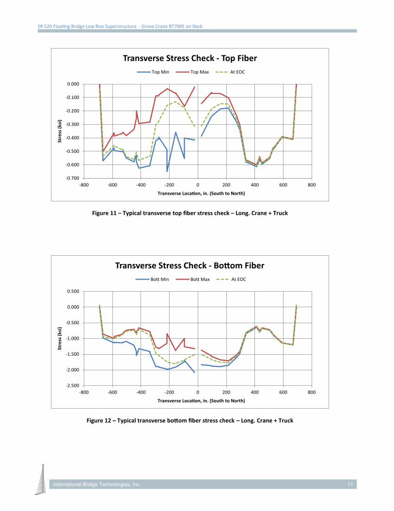
SR 520 Floating Bridge Low Rise Superstructure - Grove Crane RT700E on Deck
Figure 11 – Typical transverse top fiber stress check – Long. Crane + Truck
Figure 12 – Typical transverse bottom fiber stress check – Long. Crane + Truck
-0.700
-0.600
-0.500
-0.400
-0.300
-0.200
-0.100
0.000
-800 -600 -400 -200 0 200 400 600 800
Stre
ss (k
si)
Transverse Location, in. (South to North)
Transverse Stress Check - Top FiberTop Min Top Max At EOC
-2.500
-2.000
-1.500
-1.000
-0.500
0.000
0.500
-800 -600 -400 -200 0 200 400 600 800
Stre
ss (k
si)
Transverse Location, in. (South to North)
Transverse Stress Check - Bottom FiberBott Min Bott Max At EOC
International Bridge Technologies, Inc. 11
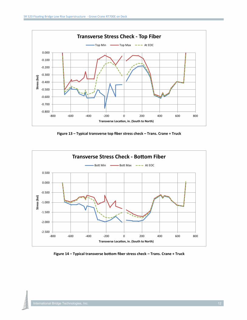
SR 520 Floating Bridge Low Rise Superstructure - Grove Crane RT700E on Deck
Figure 13 – Typical transverse top fiber stress check – Trans. Crane + Truck
Figure 14 – Typical transverse bottom fiber stress check – Trans. Crane + Truck
-0.800
-0.700
-0.600
-0.500
-0.400
-0.300
-0.200
-0.100
0.000
-800 -600 -400 -200 0 200 400 600 800
Stre
ss (k
si)
Transverse Location, in. (South to North)
Transverse Stress Check - Top FiberTop Min Top Max At EOC
-2.500
-2.000
-1.500
-1.000
-0.500
0.000
0.500
-800 -600 -400 -200 0 200 400 600 800
Stre
ss (k
si)
Transverse Location, in. (South to North)
Transverse Stress Check - Bottom FiberBott Min Bott Max At EOC
International Bridge Technologies, Inc. 12
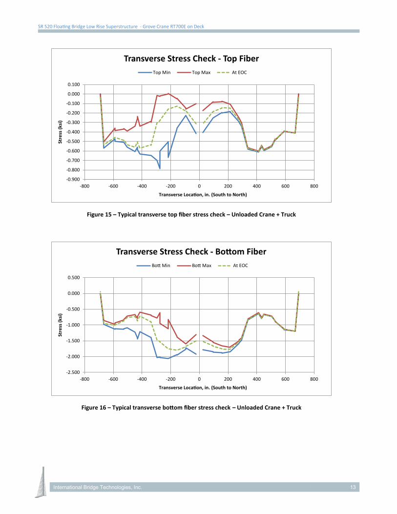
SR 520 Floating Bridge Low Rise Superstructure - Grove Crane RT700E on Deck
Figure 15 – Typical transverse top fiber stress check – Unloaded Crane + Truck
Figure 16 – Typical transverse bottom fiber stress check – Unloaded Crane + Truck
-0.900
-0.800
-0.700
-0.600
-0.500
-0.400
-0.300
-0.200
-0.100
0.000
0.100
-800 -600 -400 -200 0 200 400 600 800
Stre
ss (k
si)
Transverse Location, in. (South to North)
Transverse Stress Check - Top FiberTop Min Top Max At EOC
-2.500
-2.000
-1.500
-1.000
-0.500
0.000
0.500
-800 -600 -400 -200 0 200 400 600 800
Stre
ss (k
si)
Transverse Location, in. (South to North)
Transverse Stress Check - Bottom FiberBott Min Bott Max At EOC
International Bridge Technologies, Inc. 13
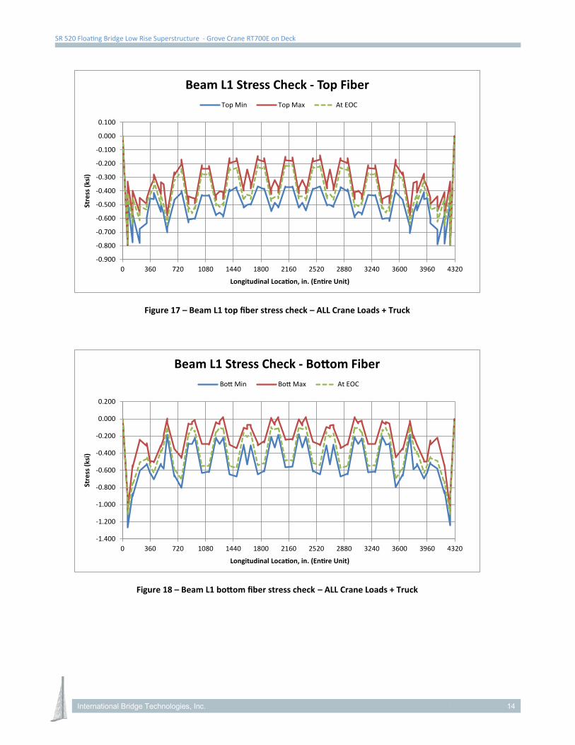
SR 520 Floating Bridge Low Rise Superstructure - Grove Crane RT700E on Deck
Figure 17 – Beam L1 top fiber stress check – ALL Crane Loads + Truck
Figure 18 – Beam L1 bottom fiber stress check – ALL Crane Loads + Truck
-0.900
-0.800
-0.700
-0.600
-0.500
-0.400
-0.300
-0.200
-0.100
0.000
0.100
0 360 720 1080 1440 1800 2160 2520 2880 3240 3600 3960 4320
Stre
ss (k
si)
Longitudinal Location, in. (Entire Unit)
Beam L1 Stress Check - Top FiberTop Min Top Max At EOC
-1.400
-1.200
-1.000
-0.800
-0.600
-0.400
-0.200
0.000
0.200
0 360 720 1080 1440 1800 2160 2520 2880 3240 3600 3960 4320
Stre
ss (k
si)
Longitudinal Location, in. (Entire Unit)
Beam L1 Stress Check - Bottom FiberBott Min Bott Max At EOC
International Bridge Technologies, Inc. 14
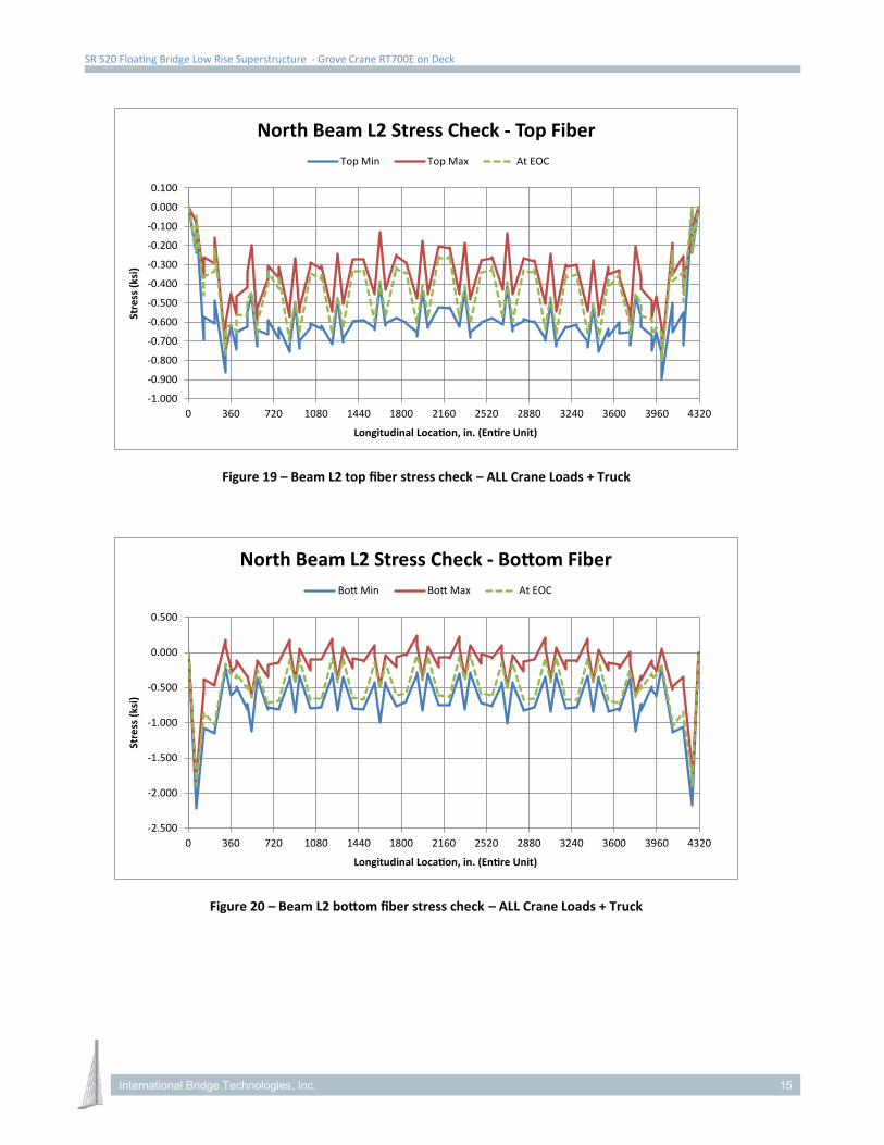
SR 520 Floating Bridge Low Rise Superstructure - Grove Crane RT700E on Deck
Figure 19 – Beam L2 top fiber stress check – ALL Crane Loads + Truck
Figure 20 – Beam L2 bottom fiber stress check – ALL Crane Loads + Truck
-1.000
-0.900
-0.800
-0.700
-0.600
-0.500
-0.400
-0.300
-0.200
-0.100
0.000
0.100
0 360 720 1080 1440 1800 2160 2520 2880 3240 3600 3960 4320
Stre
ss (k
si)
Longitudinal Location, in. (Entire Unit)
North Beam L2 Stress Check - Top FiberTop Min Top Max At EOC
-2.500
-2.000
-1.500
-1.000
-0.500
0.000
0.500
0 360 720 1080 1440 1800 2160 2520 2880 3240 3600 3960 4320
Stre
ss (k
si)
Longitudinal Location, in. (Entire Unit)
North Beam L2 Stress Check - Bottom FiberBott Min Bott Max At EOC
International Bridge Technologies, Inc. 15
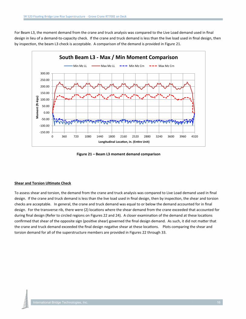
SR 520 Floating Bridge Low Rise Superstructure - Grove Crane RT700E on Deck
For Beam L3, the moment demand from the crane and truck analysis was compared to the Live Load demand used in final design in lieu of a demand-to-capacity check. If the crane and truck demand is less than the live load used in final design, then by inspection, the beam L3 check is acceptable. A comparison of the demand is provided in Figure 21.
Figure 21 – Beam L3 moment demand comparison
Shear and Torsion Ultimate Check
To assess shear and torsion, the demand from the crane and truck analysis was compared to Live Load demand used in final design. If the crane and truck demand is less than the live load used in final design, then by inspection, the shear and torsion checks are acceptable. In general, the crane and truck demand was equal to or below the demand accounted for in final design. For the transverse rib, there were (2) locations where the shear demand from the crane exceeded that accounted for during final design (Refer to circled regions on Figures 22 and 24). A closer examination of the demand at these locations confirmed that shear of the opposite sign (positive shear) governed the final design demand. As such, it did not matter that the crane and truck demand exceeded the final design negative shear at these locations. Plots comparing the shear and torsion demand for all of the superstructure members are provided in Figures 22 through 33.
-150.00
-100.00
-50.00
0.00
50.00
100.00
150.00
200.00
250.00
300.00
0 360 720 1080 1440 1800 2160 2520 2880 3240 3600 3960 4320
Mom
ent (ft
-kip
s)
Longitudinal Location, in. (Entire Unit)
South Beam L3 - Max / Min Moment ComparisonMin Mz LL Max Mz LL Min Mz Crn Max Mz Crn
International Bridge Technologies, Inc. 16
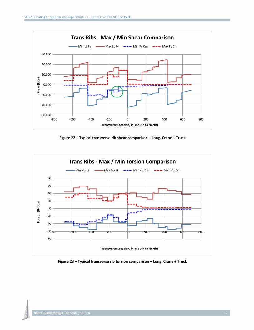
SR 520 Floating Bridge Low Rise Superstructure - Grove Crane RT700E on Deck
Figure 22 – Typical transverse rib shear comparison – Long. Crane + Truck
Figure 23 – Typical transverse rib torsion comparison – Long. Crane + Truck
-60.000
-40.000
-20.000
0.000
20.000
40.000
60.000
-800 -600 -400 -200 0 200 400 600 800
Shea
r (ki
ps)
Transverse Location, in. (South to North)
Trans Ribs - Max / Min Shear ComparisonMin LL Fy Max LL Fy Min Fy Crn Max Fy Crn
-80
-60
-40
-20
0
20
40
60
80
-800 -600 -400 -200 0 200 400 600 800
Tors
ion
(ft-k
ips)
Transverse Location, in. (South to North)
Trans Ribs - Max / Min Torsion ComparisonMin Mx LL Max Mx LL Min Mx Crn Max Mx Crn
International Bridge Technologies, Inc. 17
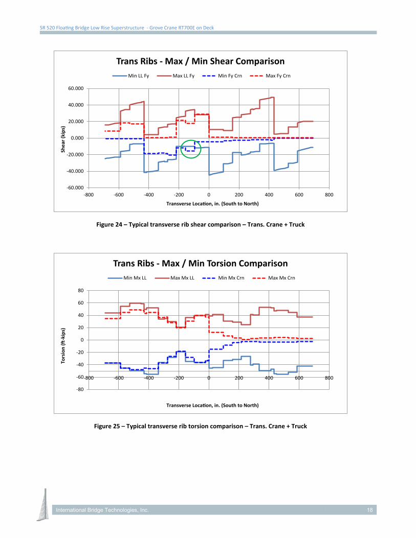
SR 520 Floating Bridge Low Rise Superstructure - Grove Crane RT700E on Deck
Figure 24 – Typical transverse rib shear comparison – Trans. Crane + Truck
Figure 25 – Typical transverse rib torsion comparison – Trans. Crane + Truck
-60.000
-40.000
-20.000
0.000
20.000
40.000
60.000
-800 -600 -400 -200 0 200 400 600 800
Shea
r (ki
ps)
Transverse Location, in. (South to North)
Trans Ribs - Max / Min Shear ComparisonMin LL Fy Max LL Fy Min Fy Crn Max Fy Crn
-80
-60
-40
-20
0
20
40
60
80
-800 -600 -400 -200 0 200 400 600 800
Tors
ion
(ft-k
ips)
Transverse Location, in. (South to North)
Trans Ribs - Max / Min Torsion ComparisonMin Mx LL Max Mx LL Min Mx Crn Max Mx Crn
International Bridge Technologies, Inc. 18
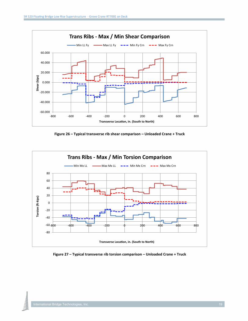
SR 520 Floating Bridge Low Rise Superstructure - Grove Crane RT700E on Deck
Figure 26 – Typical transverse rib shear comparison – Unloaded Crane + Truck
Figure 27 – Typical transverse rib torsion comparison – Unloaded Crane + Truck
-60.000
-40.000
-20.000
0.000
20.000
40.000
60.000
-800 -600 -400 -200 0 200 400 600 800
Shea
r (ki
ps)
Transverse Location, in. (South to North)
Trans Ribs - Max / Min Shear ComparisonMin LL Fy Max LL Fy Min Fy Crn Max Fy Crn
-80
-60
-40
-20
0
20
40
60
80
-800 -600 -400 -200 0 200 400 600 800
Tors
ion
(ft-k
ips)
Transverse Location, in. (South to North)
Trans Ribs - Max / Min Torsion ComparisonMin Mx LL Max Mx LL Min Mx Crn Max Mx Crn
International Bridge Technologies, Inc. 19
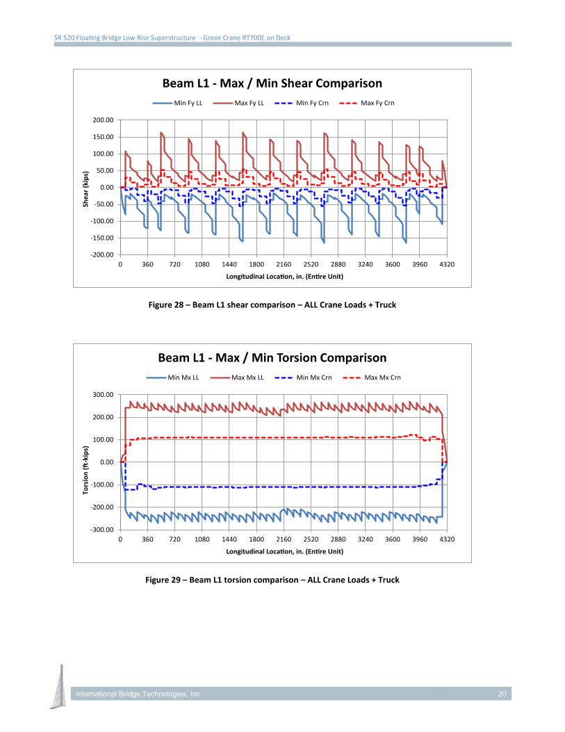
SR 520 Floating Bridge Low Rise Superstructure - Grove Crane RT700E on Deck
Figure 28 – Beam L1 shear comparison – ALL Crane Loads + Truck
Figure 29 – Beam L1 torsion comparison – ALL Crane Loads + Truck
-200.00
-150.00
-100.00
-50.00
0.00
50.00
100.00
150.00
200.00
0 360 720 1080 1440 1800 2160 2520 2880 3240 3600 3960 4320
Shea
r (ki
ps)
Longitudinal Location, in. (Entire Unit)
Beam L1 - Max / Min Shear ComparisonMin Fy LL Max Fy LL Min Fy Crn Max Fy Crn
-300.00
-200.00
-100.00
0.00
100.00
200.00
300.00
0 360 720 1080 1440 1800 2160 2520 2880 3240 3600 3960 4320
Tors
ion
(ft-k
ips)
Longitudinal Location, in. (Entire Unit)
Beam L1 - Max / Min Torsion ComparisonMin Mx LL Max Mx LL Min Mx Crn Max Mx Crn
International Bridge Technologies, Inc. 20
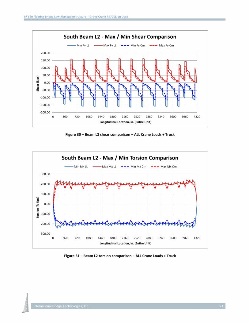
SR 520 Floating Bridge Low Rise Superstructure - Grove Crane RT700E on Deck
Figure 30 – Beam L2 shear comparison – ALL Crane Loads + Truck
Figure 31 – Beam L2 torsion comparison – ALL Crane Loads + Truck
-200.00
-150.00
-100.00
-50.00
0.00
50.00
100.00
150.00
200.00
0 360 720 1080 1440 1800 2160 2520 2880 3240 3600 3960 4320
Shea
r (ki
ps)
Longitudinal Location, in. (Entire Unit)
South Beam L2 - Max / Min Shear ComparisonMin Fy LL Max Fy LL Min Fy Crn Max Fy Crn
-300.00
-200.00
-100.00
0.00
100.00
200.00
300.00
0 360 720 1080 1440 1800 2160 2520 2880 3240 3600 3960 4320
Tors
ion
(ft-k
ips)
Longitudinal Location, in. (Entire Unit)
South Beam L2 - Max / Min Torsion ComparisonMin Mx LL Max Mx LL Min Mx Crn Max Mx Crn
International Bridge Technologies, Inc. 21
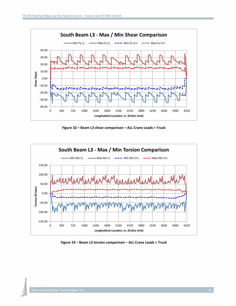
SR 520 Floating Bridge Low Rise Superstructure - Grove Crane RT700E on Deck
Figure 32 – Beam L3 shear comparison – ALL Crane Loads + Truck
Figure 33 – Beam L3 torsion comparison – ALL Crane Loads + Truck
-40.00
-30.00
-20.00
-10.00
0.00
10.00
20.00
30.00
40.00
0 360 720 1080 1440 1800 2160 2520 2880 3240 3600 3960 4320
Shea
r (ki
ps)
Longitudinal Location, in. (Entire Unit)
South Beam L3 - Max / Min Shear ComparisonMin Fy LL Max Fy LL Min Fy Crn Max Fy Crn
-150.00
-100.00
-50.00
0.00
50.00
100.00
150.00
0 360 720 1080 1440 1800 2160 2520 2880 3240 3600 3960 4320
Tors
ion
(ft-k
ips)
Longitudinal Location, in. (Entire Unit)
South Beam L3 - Max / Min Torsion ComparisonMin Mx LL Max Mx LL Min Mx Crn Max Mx Crn
International Bridge Technologies, Inc. 22

SR 520 Floating Bridge Low Rise Superstructure - Grove Crane RT700E on Deck
Local Effects
The worst-case deck load due to the crane is 40.4 kips (80.7 kip maximum outrigger load divided by 2 via spreader beam). It is required that this reaction be spread over a minimum bearing area of 12” x 12”. The bearing material shall be sufficient to evenly distribute the stress from the 40.4 kip reaction to the deck. As shown in Figure 4, the spreader beam reactions are required to be a minimum of 3’-0” from the segment joint. This restriction is to ensure that the spreader beam reactions will be located reasonably close to a transverse rib. A punching shear check was performed for the above load as shown in the appendix and was found to be acceptable.
International Bridge Technologies, Inc. 23
SR 520 Floating Bridge Low Rise Superstructure - Grove Crane RT700E on Deck
Appendix
The following is included in the Appendix:
• Grove RT700E Specifications provided by KGM • Confirmation of maximum pick of 65 kips from KGM (Conservatively assumed 80 kips in analysis). • Punching shear calculations
International Bridge Technologies, Inc. 24

productguide
features50-60 ton (50-55 mt)capacity
36 ft-1 10 ft (1 1 m-33.5 m) 4 section, full powerboom
33 ft (10.1 m) o�settablelattice swingawayextension
33 ft-56 ft (1 0.1 m-1 7.1 m)bifold lattice swingawayextension
20 ft (6.1 m) or 40 ft (12.2m) extension inserts
Grove MEGAFORM™boom
12,242 lbs (5,553 kg)Counterweight pinned tosuperstructure
240 bhp (179 kW) Tier IIICummins diesel engine
Grove “E” series cab
RT E
Rough T errain Hydraulic Crane
Features
Speci�cations
Dimensions
Working Range
Bifold
Load Charts
Working Range
Bifold & Inserts
Load Charts
Load Handling
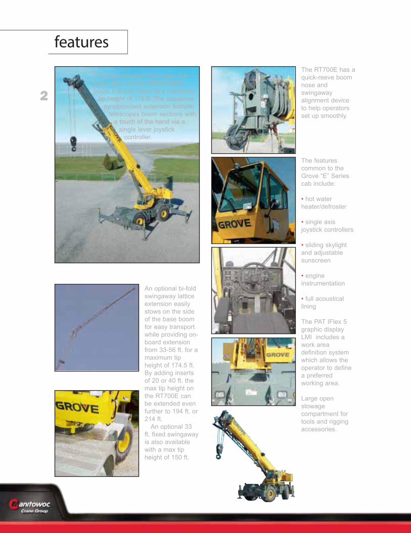
2
features
3
RT700E
speci�cations
Boom36 ft. - 110 ft. (11 m - 33.5 m) four-section, full-power sequencedsynchronized boom.Maximum tip height: 119 ft. (36.4 m).
*Optional Fixed Swingaway Extension33 ft. (10.1 m) o�settable lattice swingaway extension.O�settable at 0°, 25° and 45°. Stows alongside base boomsection. Maximum tip height: 150 ft. (45.8 m).
*Optional Bi-Fold Swingaway Extension33 ft. - 56 ft. (10.1 m - 17.1 m) bi-fold lattice swingaway extension.O�settable at 0°, 25° and 45°. Stows alongside base boomsection. Maximum tip height: 174.5 ft. (53.2 m).
*Optional 20 ft. (6.1 m) or 40 ft. (12.2 m) InsertsInstalls between boom nose and bi-fold extension, non-stowable. Maximum tip height: 194 ft. (59.1 m)-20 ft. insert, 214 ft.(65.2 m)-40 ft. insert.
Boom NoseThree nylatron sheaves (four with 60-ton rating) mounted onheavy-duty tapered roller bearings with removable pin-type ropeguards. Quick-reeve type boom nose. *Optional removable auxiliary boom nose with removable pintype rope guard.
Boom Elevation One double-acting hydraulic cylinder with integral holding valveprovides elevation from -3° to 78°.
Load Moment & Anti-Two Block System
Standard “Graphic Display” load moment and anti-two blocksystem with audio-visual warning and control lever lockout.These systems provide electronic display of boom angle, length,radius, tip height, relative load moment, maximum permissibleload, load indication and warning of impending two-blockcondition. The standard Work Area De�nition System allows theoperator to pre-select and de�ne safe working areas. If thecrane approaches the pre-set limits, audio-visual warnings aidthe operator in avoiding job-site obstructions.
CabFull-vision, all-steel fabricated with acoustical lining and tintedsafety glass throughout. Deluxe seat incorporates armrest-mounted hydraulic single-axis controllers. Dash panelincorporates gauges for all engine functions. Other standardfeatures include: hot water heater, cab circulating air fan, slidingside and rear windows, sliding skylight with electric wiper andsunscreen, electric windshield wash/wipe, �re extinguisher andseat belt.
Swing Planetary swing with foot-applied multi-disc brake. Springapplied, hydraulically-released swing brake and plunger-type,one position, mechanical house lock operated from cab.*Optional 360° mechanical swing lock. Maximum speed: 2.5RPM.
Counterweight 12,150 lbs. (5511 kg) pinned to superstructure.
Hydraulic System Three main gear pumps with a combined capacity of 103 GPM(391 LPM), 135 GPM (511 LPM) with optional air conditioning.Maximum operating pressure: 4000 psi (27.6 MPa). Twoindividual post pressure compensated valve banks.
Return line type �lter with full �ow by-pass protection andservice indicator. Replaceable cartridge with micron �ltrationrating of 5/12/16. 132 gallon (500 L) reser voir. Integral oil cooler.System pressure test ports.
Hoist Speci�cationsMain and Auxiliary Hoist: Model HP30A-19GPlanetary reduction with automatic spring applied multi-discbrake. Grooved drum. Electronic hoist drum rotation indicatorand hoist drum cable followers. Maximum Single Line Pull: 20,250 lbs
(8 246 kg)
Maximum Single Line Speed: 542 FPM(179 m/min)
Maximum Permissible Line Pull:16,800 lbs. (7 620 kg) w/standard 6 x 37 class rope16,800 lbs. (7 620 kg) w/optional 35 x 7 class rope
Rope Diameter: 3/4 in. (19 mm)
Rope Length: 500 ft. (152 m)*Optional 550 ft. (168 m) 35 x 7 class rope
Rope Type:6 x 37 class EIPS IWR C*Optional 35 x 7 class rotation resistant
Maximum Rope Stowage: 694 ft. (211 m)
Superstructure
B
B
C
Carrier
4
RT700E
speci�cations
ChassisBox section frame fabricated from high-strength, low alloy steel.Integral outrigger housings and front/rear towing and tie downlugs.
Outrigger SystemFour hydraulic telescoping single-stage double box beamoutriggers with inverted jacks and integral holding valves. Threeposition settings, 100%, 50% and fully retracted. All steelfabricated, quick-release type round outrigger �oats, 24 in. (610mm) diameter. Maximum outrigger pad load: 80,700 lbs (36,606kg).
Outrigger ControlsControls and crane level indicator located in cab.
Engine (Tier III)Cummins QSB 6.7L diesel, six cylinders, turbocharged, 240bhp (179 kW) (Gross) @ 2,500 rpm. Maximum torque: 728 ft. lbs.(987 N-m) @ 1,500 RPM.
Fuel Tank Capacity72 gallons (273 L)
TransmissionSpicer powershift with 6 forward and 6 reverse speeds (3 speeds high and 3 speeds low). Front axle disconnect for 4 x2 travel.
Electrical SystemTwo 12-volt maintenance free batteries. 12-volt starting andlighting, circuit breakers, battery disconnect switch.
Drive4 x 4
SteeringFully independent power steering:Front: Full hydraulic, steering wheel controlled.Rear: Full hydraulic, switch controlled.Provides in�nite variations of 4 main steering modes: front only,rear only, crab and coordinated. Rear steer centered indicating light.4 wheel turning radius - 22 ft. 2 in. (6.7 m).
AxlesFront: Drive/steer with di�erential and planetary
reduction hubs rigid-mounted to frame.Rear: Drive/steer with di�erential and planetary
reduction hubs pivot-mounted to frame. Automatic full hydraulic lockouts on rear axle permit8 in. (203 mm) oscillation only with boom centered over the front.
BrakesFull hydraulic split circuit brakes operating on all wheels. Spring-applied, hydraulically released axle-mounted parking brake.
Tires29.5 x 25 - 28PR bias earthmover type.
LightsFull lighting package including turn indicators, head, tail, brakeand hazard warning lights.
Maximum Speed23 MPH (37 km/h).
Gradeability (Theoretical)75% (Based on 88,236 lbs. [40 024 kg] GVW) 29.5 x 25 tires,pumps engaged, 110 ft. (33.6 m) boom, bi-fold extension, andaux. hoist.
Miscellaneous Standard EquipmentFull width steel fenders, dual rear view mirrors, hookblocktiedown, electronic back-up alarm, light package, front stowagewell, tachometer, rear wheel position indicator, 36,000 BTU hotwater heater, hoist mirrors, engine distress A/V warning system.Auxiliary hoist control valve arrangement (less hoist). Cold startaid and immersion type engine block heater, 120V 1500 watt.
*Optional Equipment*Auxiliary Hoist Package (includes Model HP30A-19G auxiliaryhoist with electronic hoist drum rotation indicator, hoist drumcable follower, 500 ft. (152 m) of 3/4 in.(19 mm) 35 X 7 class wirerope, auxiliary single sheave boom nose.)*AIR C ONDITIONING PACKAGE (includes hydraulic driven28,500 BTU air conditioning)*Auxiliary Lighting Package (includes cab mounted amber�ashing light, 360° rotation spotlight and dual base boommounted �oodlights)*CONVENIENCE PACKAGE (includes in cab LMI light bar)*“CE” Mark Conformance (includes European boom, batterydisconnect switch, 3rd wrap indicator, electric emergencyauxiliary steering, dual axis joystick controllers)*Cross axle di�erential locks (front and rear) *Full-length aluminum decking*Manual pump disconnect*Pintle hook - rear*360 degree NYC style positive swinglock*Rubber mat for stowage trough*PAT datalogger*Aluminum fender protectors
*Denotes optional equipment
F
O L
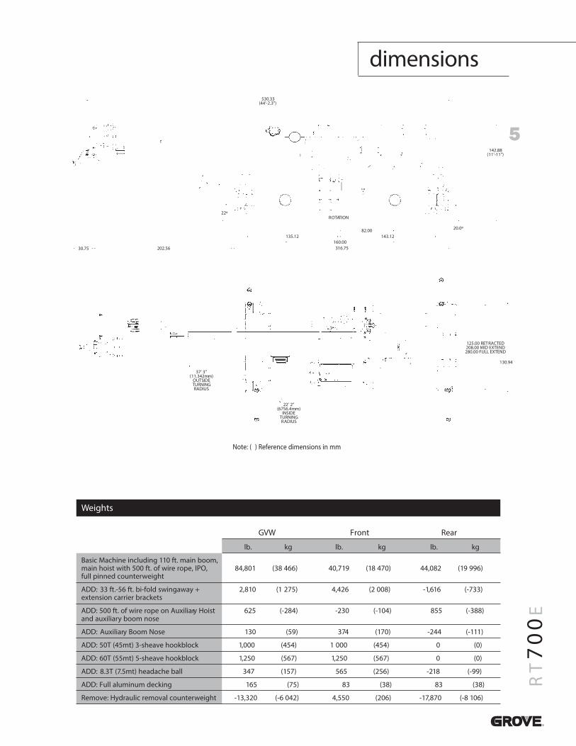
5
RT700E
dimensions
GVW Front Rear
lb. kg lb. kg lb. kg
Basic Machine including 110 ft. main boom, main hoist with 500 ft. of wire rope, IPO, 84,801 (38 466) 40,719 (18 470) 44,082 (19 996)full pinned counterweight
ADD: 33 ft.-56 ft. bi-fold swingaway + 2,810 (1 275) 4,426 (2 008) -1,616 (-733)extension carrier brackets
ADD: 500 ft. of wire rope on Auxiliary Hoist 625 (-284) -230 (-104) 855 (-388)and auxiliary boom nose
ADD: Auxiliary Boom Nose 130 (59) 374 (170) -244 (-111)
ADD: 50T (45mt) 3-sheave hookblock 1,000 (454) 1 000 (454) 0 (0)
ADD: 60T (55mt) 5-sheave hookblock 1,250 (567) 1,250 (567) 0 (0)
ADD: 8.3T (7.5mt) headache ball 347 (157) 565 (256) -218 (-99)
ADD: Full aluminum decking 165 (75) 83 (38) 83 (38)
Remove: Hydraulic removal counterweight -13,320 (-6 042) 4,550 (206) -17,870 (-8 106)
Note: ( ) Reference dimensions in mm
Weights
37’ 3”(11.342mm)
OUTSIDETURNINGRADIUS
22’ 2”(6756.4mm)
INSIDETURNINGRADIUS
130.94
125.00 RETRACTED208.00 MID EXTEND280.00 FULL EXTEND
30.75 202.56
135.12
316.75160.00
82.00143.12
22ºROTATION
20.0º
142.88(11’-11”)
530.33(44’-2.3”)
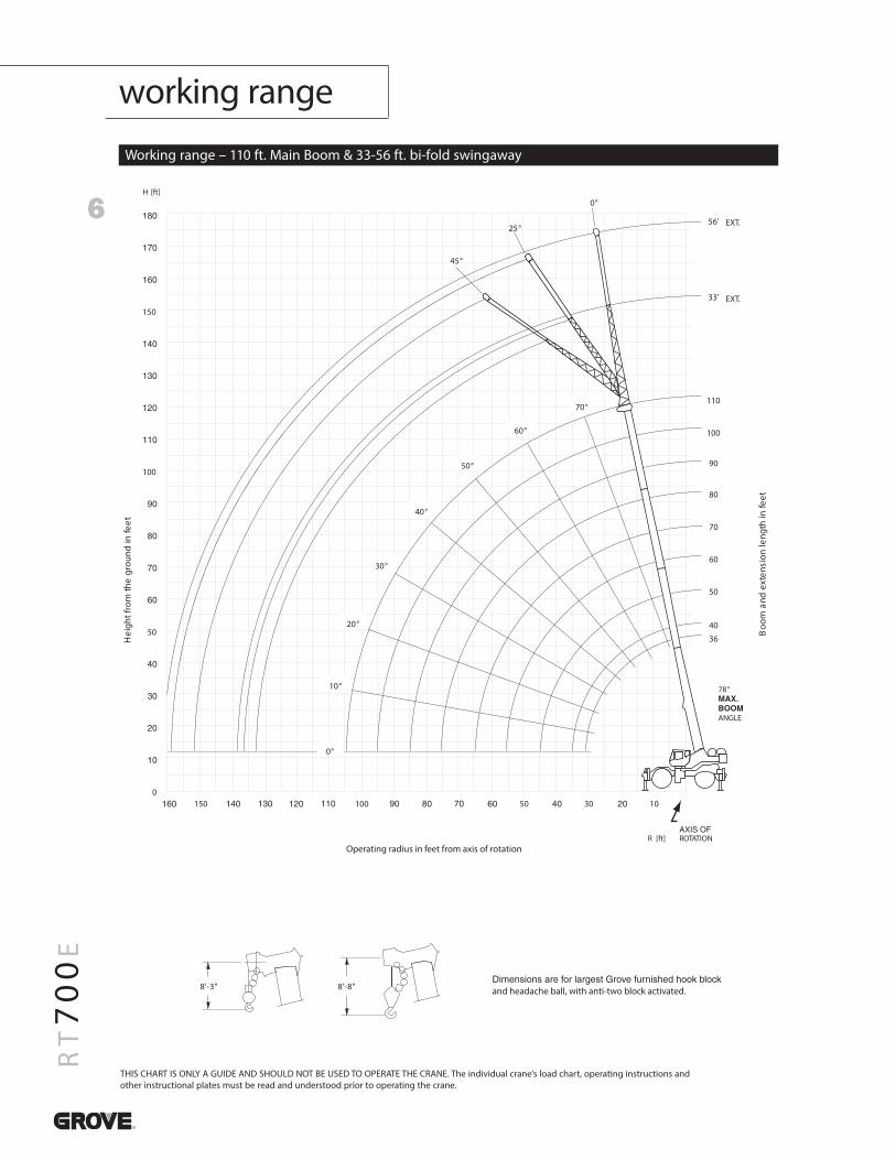
6
RT700E
working range
Working range – 110 ft. Main Boom & 33-56 ft. bi-fold swingaway
THIS CHART IS ONLY A GUIDE AND SHOULD NOT BE USED TO OPERATE THE CRANE. The individual crane’s load chart, operating instructions andother instructional plates must be read and understood prior to operating the crane.
150
100
50
0100 150 50 30 10
56'
33'
110
100
90
80
70
60
50
40
36
EXT.
EXT.
78°
ANGLE
ROTATION
Hei
ghtf
rom
the
grou
ndin
feet
Operating radius in feet from axis of rotation
Boo
man
dex
tens
ion
leng
thin
feet
0°
10°
70°
60°
50°
40°
30°
20°
and headache ball, with anti-two block activated."8-'8"3-'8
0°
25°
45°
R [ft]
H [ft]
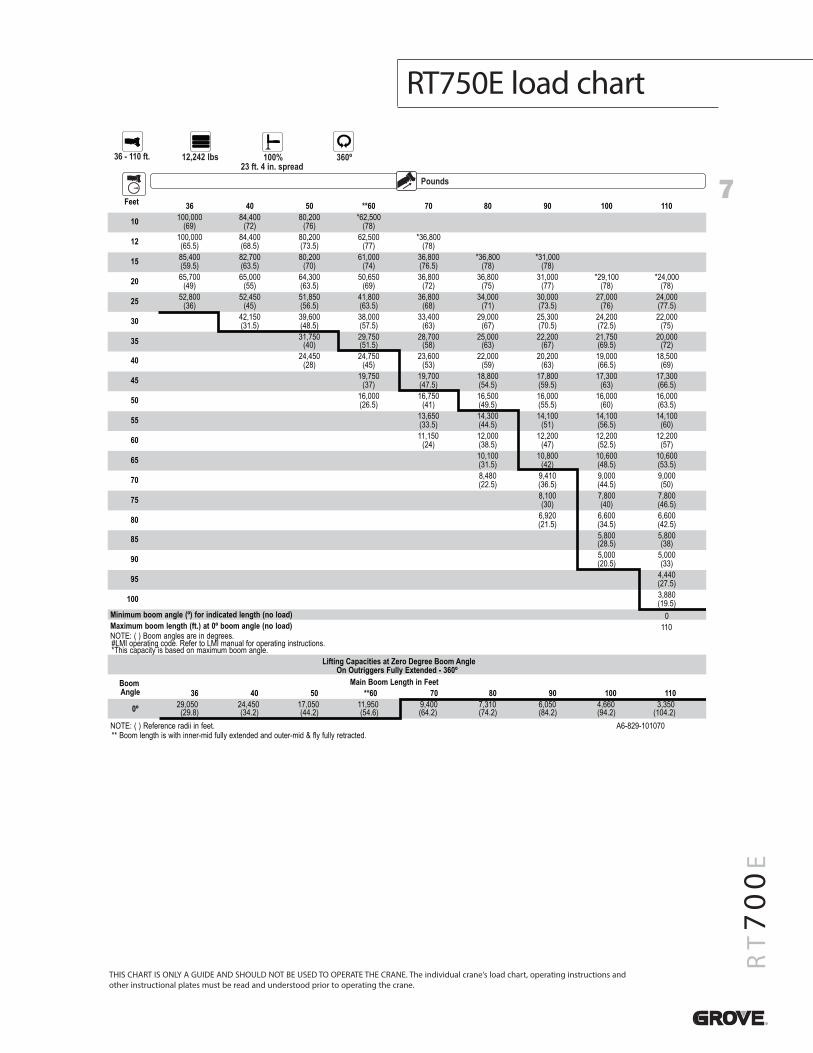
7
RT700E
RT750E load chart
THIS CHART IS ONLY A GUIDE AND SHOULD NOT BE USED TO OPERATE THE CRANE. The individual crane’s load chart, operating instructions andother instructional plates must be read and understood prior to operating the crane.
Pounds
36 - 110 ft. 12,242 lbs 100%23 ft. 4 in. spread
360º
Feet 36 40 50 **60 70 80 90 100 110
10 100,000(69)
84,400(72)
80,200(76)
*62,500(78)
12 100,000(65.5)
84,400(68.5)
80,200(73.5)
62,500(77)
*36,800(78)
15 85,400(59.5)
82,700(63.5)
80,200(70)
61,000(74)
36,800(76.5)
*36,800(78)
*31,000(78)
20 65,700(49)
65,000(55)
64,300(63.5)
50,650(69)
36,800(72)
36,800(75)
31,000(77)
*29,100(78)
*24,000(78)
25 52,800(36)
52,450(45)
51,850(56.5)
41,800(63.5)
36,800(68)
34,000(71)
30,000(73.5)
27,000(76)
24,000(77.5)
30 42,150(31.5)
39,600(48.5)
38,000(57.5)
33,400(63)
29,000(67)
25,300(70.5)
24,200(72.5)
22,000(75)
35 31,750(40)
29,750(51.5)
28,700(58)
25,000(63)
22,200(67)
21,750(69.5)
20,000(72)
40 24,450(28)
24,750(45)
23,600(53)
22,000(59)
20,200(63)
19,000(66.5)
18,500(69)
45 19,750(37)
19,700(47.5)
18,800(54.5)
17,800(59.5)
17,300(63)
17,300(66.5)
50 16,000(26.5)
16,750(41)
16,500(49.5)
16,000(55.5)
16,000(60)
16,000(63.5)
55 13,650(33.5)
14,300(44.5)
14,100(51)
14,100(56.5)
14,100(60)
60 11,150(24)
12,000(38.5)
12,200(47)
12,200(52.5)
12,200(57)
65 10,100(31.5)
10,800(42)
10,600(48.5)
10,600(53.5)
70 8,480(22.5)
9,410(36.5)
9,000(44.5)
9,000(50)
75 8,100(30)
7,800(40)
7,800(46.5)
80 6,920(21.5)
6,600(34.5)
6,600(42.5)
85 5,800(28.5)
5,800(38)
90 5,000(20.5)
5,000(33)
95 4,440(27.5)
100 3,880(19.5)
Minimum boom angle (º) for indicated length (no load) 0Maximum boom length (ft.) at 0º boom angle (no load) 110NOTE: ( ) Boom angles are in degrees.#LMI operating code. Refer to LMI manual for operating instructions.*This capacity is based on maximum boom angle.
Lifting Capacities at Zero Degree Boom AngleOn Outriggers Fully Extended - 360º
BoomAngle
Main Boom Length in Feet36 40 50 **60 70 80 90 100 110
0º 29,050(29.8)
24,450(34.2)
17,050(44.2)
11,950(54.6)
9,400(64.2)
7,310(74.2)
6,050(84.2)
4,660(94.2)
3,350(104.2)
NOTE: ( ) Reference radii in feet.** Boom length is with inner-mid fully extended and outer-mid & fly fully retracted.
A6-829-101070
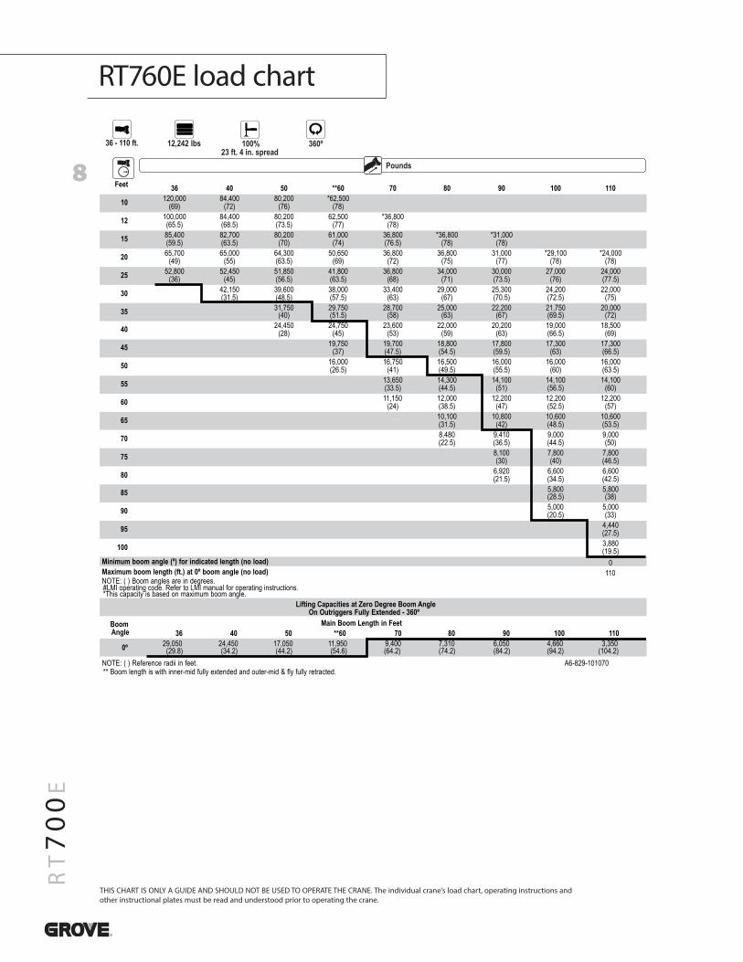
8
RT700E
RT760E load chart
THIS CHART IS ONLY A GUIDE AND SHOULD NOT BE USED TO OPERATE THE CRANE. The individual crane’s load chart, operating instructions andother instructional plates must be read and understood prior to operating the crane.
Pounds
36 - 110 ft. 12,242 lbs 100%23 ft. 4 in. spread
360º
Feet 36 40 50 **60 70 80 90 100 110
10 120,000(69)
84,400(72)
80,200(76)
*62,500(78)
12 100,000(65.5)
84,400(68.5)
80,200(73.5)
62,500(77)
*36,800(78)
15 85,400(59.5)
82,700(63.5)
80,200(70)
61,000(74)
36,800(76.5)
*36,800(78)
*31,000(78)
20 65,700(49)
65,000(55)
64,300(63.5)
50,650(69)
36,800(72)
36,800(75)
31,000(77)
*29,100(78)
*24,000(78)
25 52,800(36)
52,450(45)
51,850(56.5)
41,800(63.5)
36,800(68)
34,000(71)
30,000(73.5)
27,000(76)
24,000(77.5)
30 42,150(31.5)
39,600(48.5)
38,000(57.5)
33,400(63)
29,000(67)
25,300(70.5)
24,200(72.5)
22,000(75)
35 31,750(40)
29,750(51.5)
28,700(58)
25,000(63)
22,200(67)
21,750(69.5)
20,000(72)
40 24,450(28)
24,750(45)
23,600(53)
22,000(59)
20,200(63)
19,000(66.5)
18,500(69)
45 19,750(37)
19,700(47.5)
18,800(54.5)
17,800(59.5)
17,300(63)
17,300(66.5)
50 16,000(26.5)
16,750(41)
16,500(49.5)
16,000(55.5)
16,000(60)
16,000(63.5)
55 13,650(33.5)
14,300(44.5)
14,100(51)
14,100(56.5)
14,100(60)
60 11,150(24)
12,000(38.5)
12,200(47)
12,200(52.5)
12,200(57)
65 10,100(31.5)
10,800(42)
10,600(48.5)
10,600(53.5)
70 8,480(22.5)
9,410(36.5)
9,000(44.5)
9,000(50)
75 8,100(30)
7,800(40)
7,800(46.5)
80 6,920(21.5)
6,600(34.5)
6,600(42.5)
85 5,800(28.5)
5,800(38)
90 5,000(20.5)
5,000(33)
95 4,440(27.5)
100 3,880(19.5)
Minimum boom angle (º) for indicated length (no load) 0Maximum boom length (ft.) at 0º boom angle (no load) 110NOTE: ( ) Boom angles are in degrees.#LMI operating code. Refer to LMI manual for operating instructions.*This capacity is based on maximum boom angle.
Lifting Capacities at Zero Degree Boom AngleOn Outriggers Fully Extended - 360º
BoomAngle
Main Boom Length in Feet36 40 50 **60 70 80 90 100 110
0º 29,050(29.8)
24,450(34.2)
17,050(44.2)
11,950(54.6)
9,400(64.2)
7,310(74.2)
6,050(84.2)
4,660(94.2)
3,350(104.2)
NOTE: ( ) Reference radii in feet.** Boom length is with inner-mid fully extended and outer-mid & fly fully retracted.
A6-829-101070
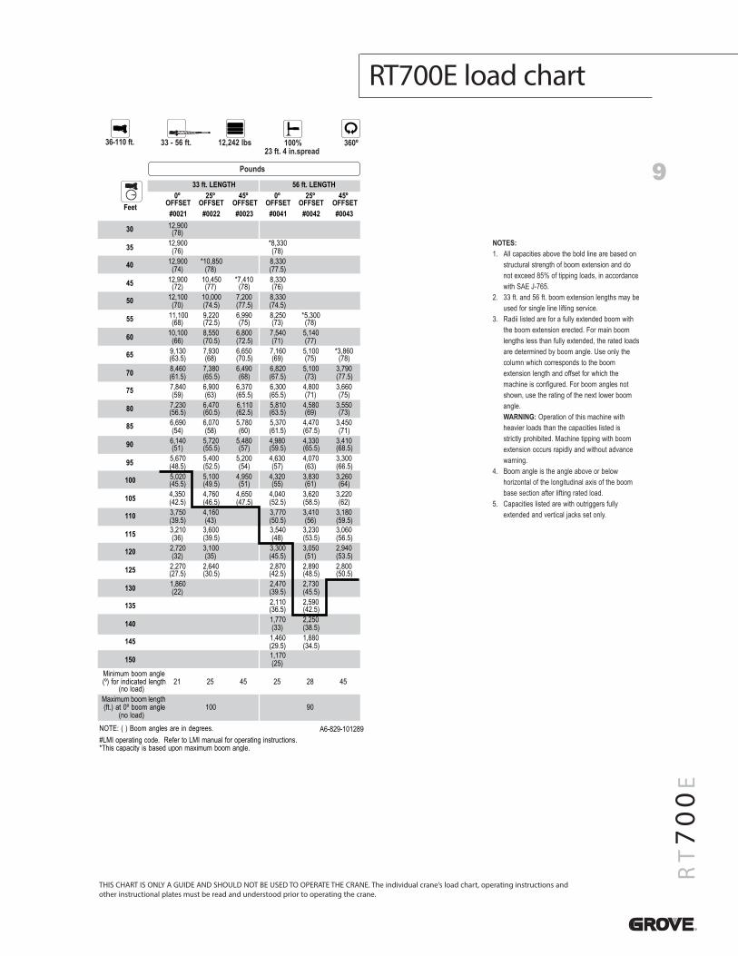
RT700E load chart
9
RT700E
NOTES:1. All capacities above the bold line are based on
structural strength of boom extension and donot exceed 85% of tipping loads, in accordancewith SAE J-765.
2. 33 ft. and 56 ft. boom extension lengths may beused for single line lifting service.
3. Radii listed are for a fully extended boom withthe boom extension erected. For main boomlengths less than fully extended, the rated loadsare determined by boom angle. Use only thecolumn which corresponds to the boomextension length and offset for which themachine is configured. For boom angles notshown, use the rating of the next lower boomangle.WARNING: Operation of this machine withheavier loads than the capacities listed isstrictly prohibited. Machine tipping with boomextension occurs rapidly and without advancewarning.
4. Boom angle is the angle above or belowhorizontal of the longitudinal axis of the boombase section after lifting rated load.
5. Capacities listed are with outriggers fullyextended and vertical jacks set only.
THIS CHART IS ONLY A GUIDE AND SHOULD NOT BE USED TO OPERATE THE CRANE. The individual crane’s load chart, operating instructions andother instructional plates must be read and understood prior to operating the crane.
Pounds
36-110 ft. 12,242 lbs33 - 56 ft.
100%23 ft. 4 in.spread
360º
Feet
33 ft. LENGTH 56 ft. LENGTH0º
OFFSET25º
OFFSET45º
OFFSET0º
OFFSET25º
OFFSET45º
OFFSET#0021 #0022 #0023 #0041 #0042 #0043
30 12,900(78)
35 12,900(76)
*8,330(78)
40 12,900(74)
*10,850(78)
8,330(77.5)
45 12,900(72)
10,450(77)
*7,410(78)
8,330(76)
50 12,100(70)
10,000(74.5)
7,200(77.5)
8,330(74.5)
55 11,100(68)
9,220(72.5)
6,990(75)
8,250(73)
*5,300(78)
60 10,100(66)
8,550(70.5)
6,800(72.5)
7,540(71)
5,140(77)
65 9,130(63.5)
7,930(68)
6,650(70.5)
7,160(69)
5,100(75)
*3,860(78)
70 8,460(61.5)
7,380(65.5)
6,490(68)
6,820(67.5)
5,100(73)
3,790(77.5)
75 7,840(59)
6,900(63)
6,370(65.5)
6,300(65.5)
4,800(71)
3,660(75)
80 7,230(56.5)
6,470(60.5)
6,110(62.5)
5,810(63.5)
4,580(69)
3,550(73)
85 6,690(54)
6,070(58)
5,780(60)
5,370(61.5)
4,470(67.5)
3,450(71)
90 6,140(51)
5,720(55.5)
5,480(57)
4,980(59.5)
4,330(65.5)
3,410(68.5)
95 5,670(48.5)
5,400(52.5)
5,200(54)
4,630(57)
4,070(63)
3,300(66.5)
100 5,020(45.5)
5,100(49.5)
4,950(51)
4,320(55)
3,830(61)
3,260(64)
105 4,350(42.5)
4,760(46.5)
4,650(47.5)
4,040(52.5)
3,620(58.5)
3,220(62)
110 3,750(39.5)
4,160(43)
3,770(50.5)
3,410(56)
3,180(59.5)
115 3,210(36)
3,600(39.5)
3,540(48)
3,230(53.5)
3,060(56.5)
120 2,720(32)
3,100(35)
3,300(45.5)
3,050(51)
2,940(53.5)
125 2,270(27.5)
2,640(30.5)
2,870(42.5)
2,890(48.5)
2,800(50.5)
130 1,860(22)
2,470(39.5)
2,730(45.5)
135 2,110(36.5)
2,590(42.5)
140 1,770(33)
2,250(38.5)
145 1,460(29.5)
1,880(34.5)
150 1,170(25)
Minimum boom angle(º) for indicated length
(no load)21 25 45 25 28 45
Maximum boom length(ft.) at 0º boom angle
(no load)09001
NOTE: ( ) Boom angles are in degrees. A6-829-101289#LMI operating code. Refer to LMI manual for operating instructions.*This capacity is based upon maximum boom angle.
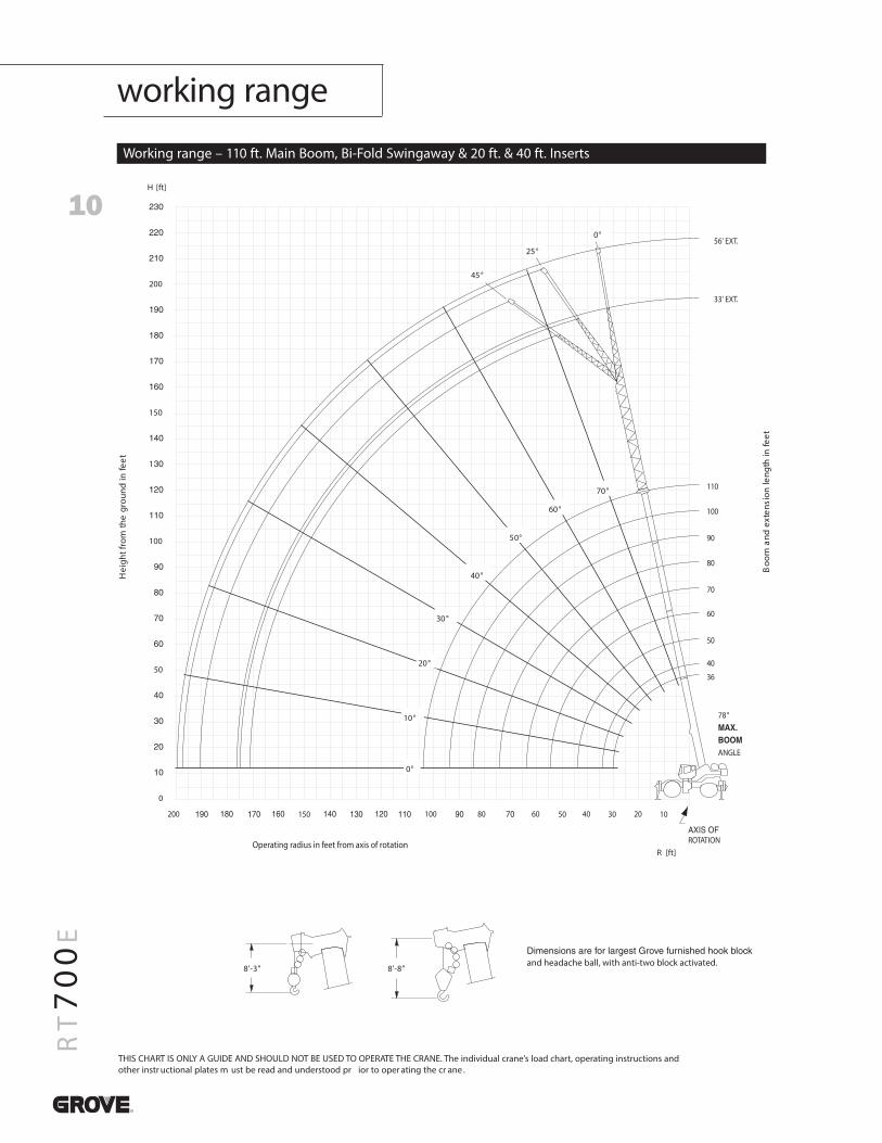
10
RT700E
Working range – 110 ft. Main Boom, Bi-Fold Swingaway & 20 ft. & 40 ft. Inserts
THIS CHART IS ONLY A GUIDE AND SHOULD NOT BE USED TO OPERATE THE CRANE. The individual crane’s load chart, operating instructions andother instr uctional plates m ust be read and understood pr ior to oper ating the cr ane .
200
150
1
100
50
0
200 100 80 60 40 20150 50 30 10
56' EXT.
33' EXT.
110
100
90
80
70
60
50
40
36
78°
ANGLE
ROTATIONOperating radius in feet from axis of rotation
and headache ball, with anti-two block activated."8-'8"3-'8
45°
25°
0°
0°
10°
20°
30°
40°
50°
60°
70°
Hei
ghtf
rom
the
grou
ndin
feet
Boo
man
dex
tens
ion
leng
thin
feet
H [ft]
R [ft]
working range
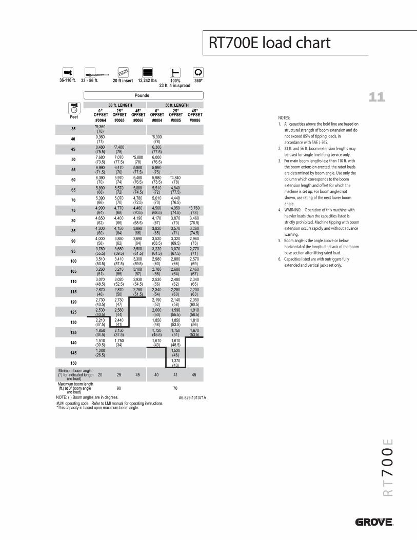
11
RT700E
RT700E load chart
NOTES:1. All capacities above the bold line are based on
structural strength of boom extension and donot exceed 85% of tipping loads, inaccordance with SAE J-765.
2. 33 ft. and 56 ft. boom extension lengths maybe used for single line lifting service only.
3. For main boom lengths less than 110 ft. withthe boom extension erected, the rated loadsare determined by boom angle. Use only thecolumn which corresponds to the boomextension length and o�set for which themachine is set up. For boom angles notshown, use rating of the next lower boomangle.
4. WARNING: Operation of this machine withheavier loads than the capacities listed isstrictly prohibited. Machine tipping with boomextension occurs rapidly and without advancewarning.
5. Boom angle is the angle above or belowhorizontal of the longitudinal axis of the boombase section after lifting rated load.
6. Capacities listed are with outriggers fullyextended and vertical jacks set only.
Pounds
36-110 ft. 12,242 lbs33 - 56 ft.
100%23 ft. 4 in.spread
360º
Feet
33 ft. LENGTH 56 ft. LENGTH0°
OFFSET25°
OFFSET45°
OFFSET0°
OFFSET25°
OFFSET45°
OFFSET#0064 #0065 #0066 #0084 #0085 #0086
35 *9,360(78)
40 9,360(77)
*6,300(78)
45 8,480(75.5)
*7,480(78)
6,300(77.5)
50 7,680(73.5)
7,070(77.5)
*5,880(78)
6,000(76.5)
55 6,990(71.5)
6,470(76)
5,880(77.5)
5,990(75)
60 6,390(70)
5,970(74)
5,480(76.5)
5,980(73.5)
*4,840(78)
65 5,890(68)
5,570(72)
5,080(74.5)
5,510(72)
4,840(77.5)
70 5,390(66)
5,070(70)
4,780(72.5)
5,010(70)
4,440(76.5)
75 4,990(64)
4,770(68)
4,480(70.5)
4,560(68.5)
4,050(74.5)
*3,760(78)
80 4,650(62)
4,400(66)
4,190(68.5)
4,170(67)
3,870(73)
3,460(76.5)
85 4,300(60)
4,150(64)
3,890(66)
3,820(65)
3,570(71)
3,260(74.5)
90 4,000(58)
3,850(62)
3,690(64)
3,520(63.5)
3,320(69.5)
2,960(73)
95 3,760(55.5)
3,650(59.5)
3,500(61.5)
3,220(61.5)
3,070(67.5)
2,770(71)
100 3,510(53.5)
3,410(57.5)
3,300(59.5)
2,980(60)
2,880(66)
2,570(69)
105 3,260(51)
3,210(55)
3,100(57)
2,780(58)
2,680(64)
2,460(67)
110 3,070(48.5)
3,020(52.5)
2,930(54.5)
2,530(56)
2,480(62)
2,340(65)
115 2,870(46)
2,870(50)
2,780(51.5)
2,340(54)
2,280(60)
2,200(63)
120 2,730(43.5)
2,730(47)
2,190(52)
2,140(58)
2,050(60.5)
125 2,530(40.5)
2,580(44)
2,000(50)
1,990(55.5)
1,910(58.5)
130 2,210(37.5)
2,440(41)
1,850(48)
1,850(53.5)
1,810(56)
135 1,850(34.5)
2,150(37.5)
1,720(45.5)
1,750(51)
1,670(53.5)
140 1,510(30.5)
1,750(34)
1,610(43)
1,610(48.5)
145 1,200(26.5)
1,520(46)
150 1,370(43)
Minimum boom angle(°) for indicated length
(no load)20 25 45 40 41 45
Maximum boom length(ft.) at 0° boom angle
(no load)0709
NOTE: ( ) Boom angles are in degrees. A6-829-101371A#LMI operating code. Refer to LMI manual for operating instructions.*This capacity is based upon maximum boom angle.
20 ft insert
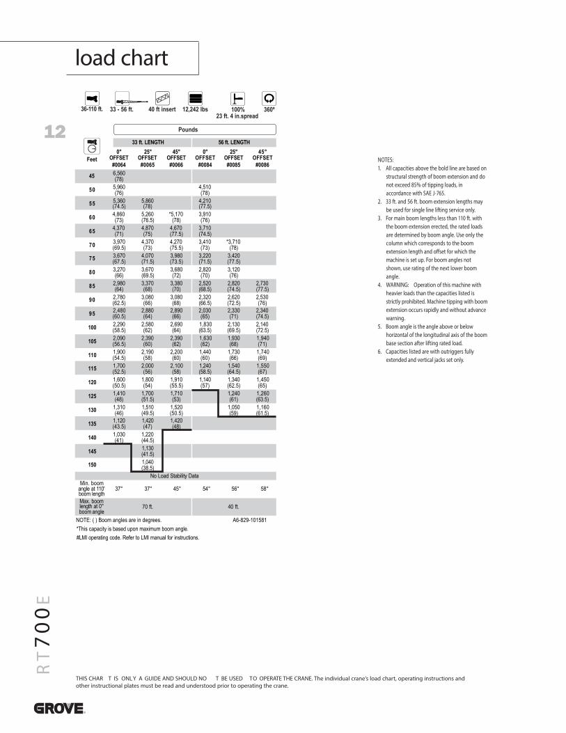
12
RT700E
load chart
THIS CHAR T IS ONLY A GUIDE AND SHOULD NO T BE USED TO OPERATE THE CRANE. The individual crane’s load chart, operating instructions andother instructional plates must be read and understood prior to operating the crane.
NOTES:1. All capacities above the bold line are based on
structural strength of boom extension and donot exceed 85% of tipping loads, inaccordance with SAE J-765.
2. 33 ft. and 56 ft. boom extension lengths maybe used for single line lifting service only.
3. For main boom lengths less than 110 ft. withthe boom extension erected, the rated loadsare determined by boom angle. Use only thecolumn which corresponds to the boomextension length and o�set for which themachine is set up. For boom angles notshown, use rating of the next lower boomangle.
4. WARNING: Operation of this machine withheavier loads than the capacities listed isstrictly prohibited. Machine tipping with boomextension occurs rapidly and without advancewarning.
5. Boom angle is the angle above or belowhorizontal of the longitudinal axis of the boombase section after lifting rated load.
6. Capacities listed are with outriggers fullyextended and vertical jacks set only.
Pounds
36-110 ft. 12,242 lbs33 - 56 ft. 100%23 ft. 4 in.spread
360º
Feet
33 ft. LENGTH 56 ft. LENGTH
#0064 #0065 #0066 #0084 #0085 #0086
0°OFFSET
25°OFFSET
45°OFFSET
0°OFFSET
25°OFFSET
45°OFFSET
45 6,560(78)
50 5,960(76)
4,510(78)
55 5,360(74.5)
5,860(78)
4,210(77.5)
60 4,860(73)
5,260(76.5)
*5,170(78)
3,910(76)
65 4,370(71)
4,870(75)
4,670(77.5)
3,710(74.5)
70 3,970(69.5)
4,370(73)
4,270(75.5)
3,410(73)
*3,710(78)
75 3,670(67.5)
4,070(71.5)
3,980(73.5)
3,220(71.5)
3,420(77.5)
80 3,270(66)
3,670(69.5)
3,680(72)
2,820(70)
3,120(76)
85 2,980(64)
3,370(68)
3,380(70)
2,520(68.5)
2,820(74.5)
2,730(77.5)
90 2,780(62.5)
3,080(66)
3,080(68)
2,320(66.5)
2,620(72.5)
2,530(76)
95 2,480(60.5)
2,880(64)
2,890(66)
2,030(65)
2,330(71)
2,340(74.5)
100 2,290(58.5)
2,580(62)
2,690(64)
1,830(63.5)
2,130(69.5)
2,140(72.5)
105 2,090(56.5)
2,390(60)
2,390(62)
1,630(62)
1,930(68)
1,940(71)
110 1,900(54.5)
2,190(58)
2,200(60)
1,440(60)
1,730(66)
1,740(69)
115 1,700(52.5)
2,000(56)
2,100(58)
1,240(58.5)
1,540(64.5)
1,550(67)
120 1,600(50.5)
1,800(54)
1,910(55.5)
1,140(57)
1,340(62.5)
1,450(65)
125 1,410(48)
1,700(51.5)
1,710(53)
1,240(61)
1,260(63.5)
130 1,310(46)
1,510(49.5)
1,520(50.5)
1,050(59)
1,160(61.5)
135 1,120(43.5)
1,420(47)
1,420(48)
140 1,030(41)
1,220(44.5)
145 1,130(41.5)
150 1,040(38.5)
Min. boomangle at 110'boom length
37° 37° 45° 54° 56° 58°
Max. boomlength at 0°boom angle
.tf 04.tf 07
.seerged ni era selgna mooB ) ( :ETON A6-829-101581*This capacity is based upon maximum boom angle.#LMI operating code. Refer to LMI manual for instructions.
No Load Stability Data
40 ft insert
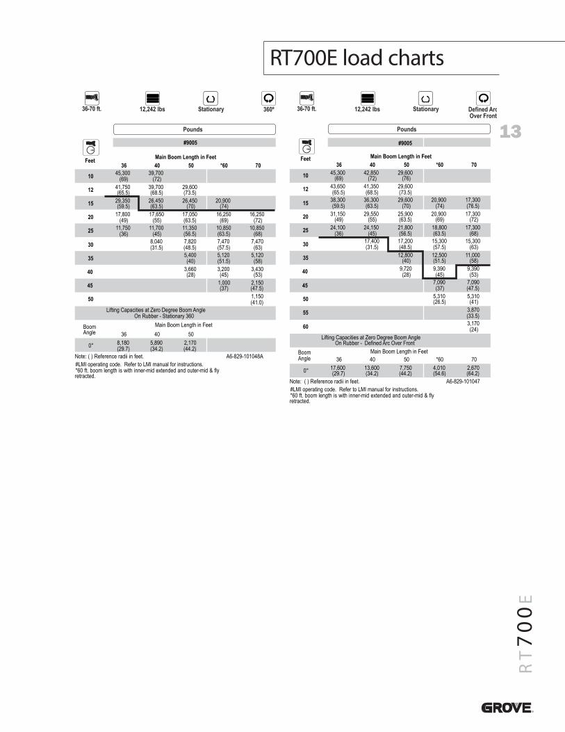
13
RT700E
RT700E load charts
Pounds
36-70 ft. 12,242 lbs Stationary 360º
Feet Main Boom Length in Feet36 40 50 *60 70
10 45,300(69)
39,700(72)
12 41,750(65.5)
39,700(68.5)
29,600(73.5)
15 29,350(59.5)
26,450(63.5)
26,450(70)
20,900(74)
20 17,800(49)
17,650(55)
17,050(63.5)
16,250(69)
16,250(72)
25 11,750(36)
11,700(45)
11,350(56.5)
10,850(63.5)
10,850(68)
30 8,040(31.5)
7,820(48.5)
7,470(57.5)
7,470(63)
35 5,400(40)
5,120(51.5)
5,120(58)
40 3,660(28)
3,200(45)
3,430(53)
45 1,000(37)
2,150(47.5)
50 1,150(41.0)
BoomAngle
Main Boom Length in Feet36 40 50
0° 8,180(29.7)
5,890(34.2)
2,170(44.2)
A840101-928-6A.teef ni iidar ecnerefeR ) ( :etoN#LMI operating code. Refer to LMI manual for instructions.*60 ft. boom length is with inner-mid extended and outer-mid & flyretracted.
Lifting Capacities at Zero Degree Boom AngleOn Rubber - Stationary 360
#9005
Pounds
Stationary
Feet
#9005
Main Boom Length in Feet36 40 50 *60 70
10 45,300(69)
42,850(72)
29,600(76)
12 43,650(65.5)
41,350(68.5)
29,600(73.5)
15 38,300(59.5)
36,300(63.5)
29,600(70)
20,900(74)
17,300(76.5)
20 31,150(49)
29,550(55)
25,900(63.5)
20,900(69)
17,300(72)
25 24,100(36)
24,150(45)
21,800(56.5)
18,800(63.5)
17,300(68)
30 17,400(31.5)
17,200(48.5)
15,300(57.5)
15,300(63)
35 12,800(40)
12,500(51.5)
11,000(58)
40 9,720(28)
9,390(45)
9,390(53)
45 7,090(37)
7,090(47.5)
50 5,310(26.5)
5,310(41)
55 3,870(33.5)
60 3,170(24)
BoomAngle
Main Boom Length in Feet36 40 50 *60 70
0° 17,600(29.7)
13,600(34.2)
7,750(44.2)
4,010(54.6)
2,670(64.2)
740101-928-6A.teef ni iidar ecnerefeR ) ( :etoN#LMI operating code. Refer to LMI manual for instructions.*60 ft. boom length is with inner-mid extended and outer-mid & flyretracted.
Lifting Capacities at Zero Degree Boom AngleOn Rubber - Defined Arc Over Front
36-70 ft. 12,242 lbs Defined ArcOver Front
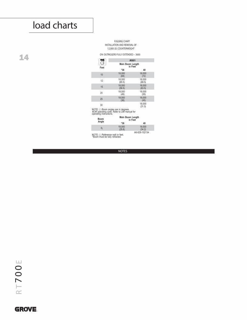
14
RT700E
load charts
Feet
#0801Main Boom Length
in Feet*36 40
10 18,000(69)
18,000(72)
12 18,000(65.5)
18,000(68.5)
15 18,000(59.5)
18,000(63.5)
20 18,000(49)
18,000(55)
25 18,000(36)
18,000(45)
30 18,000(31.5)
NOTE: ( ) Boom angles are in degrees.#LMI operating code. Refer to LMI manual foroperating instructions.
BoomAngle
Main Boom Lengthin Feet
*36 40
0¡ 18,000(29.8)
18,000(34.2)
A6-829-102134NOTE: ( ) Reference radii in feet.*Boom must be fully retracted.
R IGGING CHARTINSTALLATION AND REMOVAL OF
12,000 LB. COUNTERWEIGHT
ON OUTRIGGERS FULLY EXTENDED – 3600
NOTES
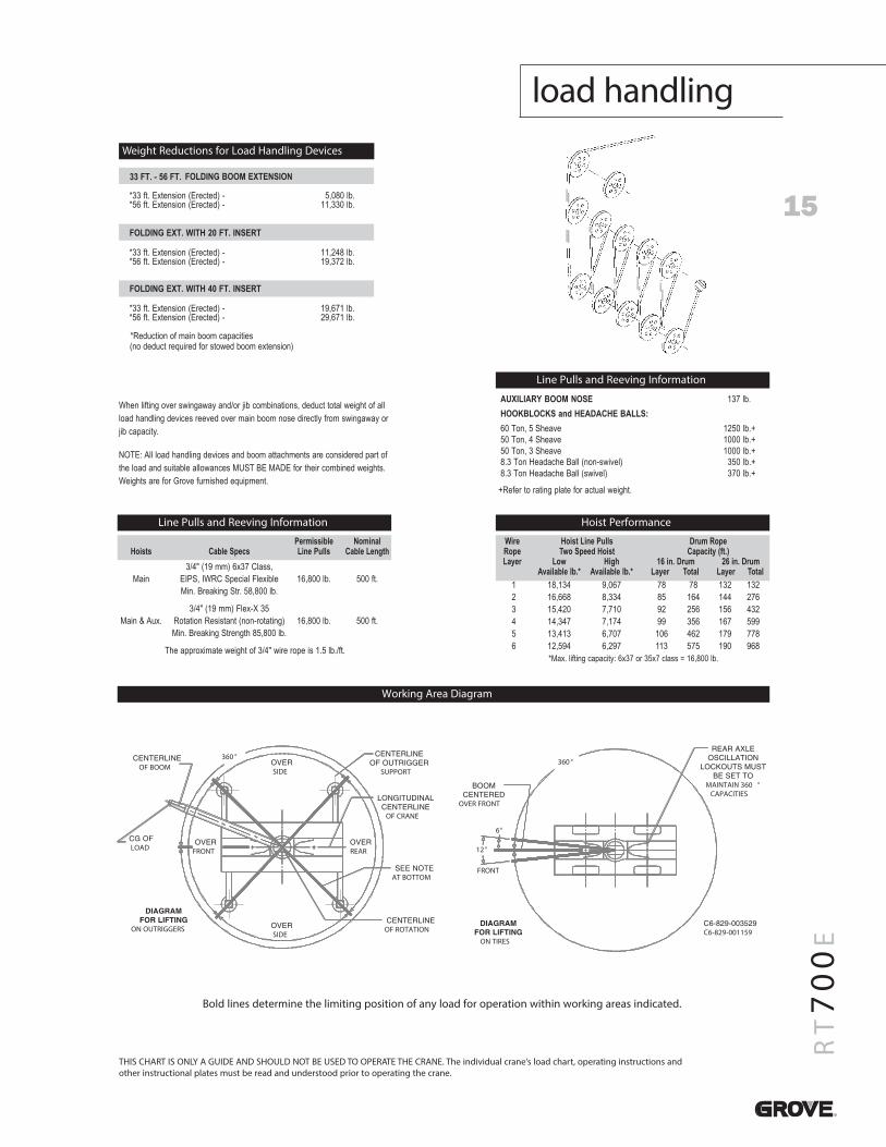
15
RT700E
load handling
THIS CHART IS ONLY A GUIDE AND SHOULD NOT BE USED TO OPERATE THE CRANE. The individual crane’s load chart, operating instructions andother instructional plates must be read and understood prior to operating the crane.
Line Pulls and Reeving Information
MAINTAIN 360 °CAPACITIES
OVER FRONT
ON TIRESC6-829-001159
FRONT
360 °
12°
6°
OF BOOM
ON OUTRIGGERS
SUPPORT
OF CRANE
AT BOTTOM
OF ROTATION
LOAD FRONT REAR
SIDE
SIDE
360 °
Working Area Diagram
Bold lines determine the limiting position of any load for operation within working areas indicated.
When lifting over swingaway and/or jib combinations, deduct total weight of allload handling devices reeved over main boom nose directly from swingaway orjib capacity.
NOTE: All load handling devices and boom attachments are considered part ofthe load and suitable allowances MUST BE MADE for their combined weights.Weights are for Grove furnished equipment.
Weight Reductions for Load Handling Devices
Wire Hoist Line Pulls Drum RopeRope Two Speed Hoist Capacity (ft.)Layer Low High 16 in. Drum 26 in. Drum
Available lb.* Available lb.* Layer Total Layer Total1 18,134 9,067 78 78 132 1322 16,668 8,334 85 164 144 2763 15,420 7,710 92 256 156 4324 14,347 7,174 99 356 167 5995 13,413 6,707 106 462 179 7786 12,594 6,297 113 575 190 968
*Max. lifting capacity: 6x37 or 35x7 class = 16,800 lb.
Hoist Performance
Permissible NominalHoists Cable Specs Line Pulls Cable Length
3/4" (19 mm) 6x37 Class,Main EIPS, IWRC Special Flexible 16,800 lb. 500 ft.
Min. Breaking Str. 58,800 lb.
3/4" (19 mm) Flex-X 35Main & Aux. Rotation Resistant (non-rotating) 16,800 lb. 500 ft.
Min. Breaking Strength 85,800 lb.
The approximate weight of 3/4" wire rope is 1.5 lb./ft.
Line Pulls and Reeving Information
33 FT. - 56 FT. FOLDING BOOM EXTENSION
.bl 080,5- )detcerE( noisnetxE .tf 33** .bl 033,11- )detcerE( noisnetxE .tf 65
FOLDING EXT. WITH 20 FT. INSERT
.bl 842,11- )detcerE( noisnetxE .tf 33*
.bl 273,91- )detcerE( noisnetxE .tf 65*
FOLDING EXT. WITH 40 FT. INSERT
* .bl 176,91- )detcerE( noisnetxE .tf 33* .bl 176,92- )detcerE( noisnetxE .tf 65
*Reduction of main boom capacities(no deduct required for stowed boom extension)
AUXILIARY BOOM NOSE 137 lb.HOOKBLOCKS and HEADACHE BALLS:
+.bl 0521evaehS 5 ,noT 06+.bl 0001evaehS 4 ,noT 05+.bl 0001evaehS 3 ,noT 05+.bl 053)leviws-non( llaB ehcadaeH noT 3.8+.bl 073)leviws( llaB ehcadaeH noT 3.8
+Refer to rating plate for actual weight.

Constant improvement and engineering progress make it necessar y that we reserve the right to makespeci�cation, equipment, and price changes without notice. Illustrations shown may include optional equipmentand accessories, and may not include all standard equipment.
1205-2M Printed in USA Form No. RT700E PG Part No. 03-474 Manitowoc Crane Group 2005
Manitowoc Crane Group - AmericasManitowoc, Wisconsin FacilityTel: [Int + 001] 920 684 6621Fax: [Int + 001] 920 683 6277Shady Grove, Pennsylvania Facility Tel: [Int + 001] 717 597 8121Fax: [Int + 001] 717 597 4062
Manitowoc Crane Group - EMEAEurope Middle East & AfricaTel: [Int + 33] (0) 191 565 6281Fax: [Int + 33] (0) 4 72 18 20 20
Manitowoc Crane Group - UKEurope Middle East & AfricaTel: [Int + 44] (0) 191 565 6281Fax: [Int + 44] (0) 191 564 0442
Manitowoc Crane Group - Germany(Sales, Parts & Service) Tel: [Int + 49](0) 2173 8909 0Fax: [Int + 49] (0) 2173 8909-30
Manitowoc Crane Group - FranceFrance & Africa (Sales, Parts & Service)Tel: [Int + 33] (0) 1 303 13150 Fax: [Int + 33] (0) 1 303 86085
Manitowoc Crane Group - Netherlands(Sales, Parts & Service)Tel: [Int + 31] (0) 76 578 39 99 Fax: [Int + 31] (0) 76 578 39 78
Manitowoc Crane Group - ItalyItaly & Southern Europe (Sales, Parts & Service)Tel: [Int + 39] (0) 331 49 33 11 Fax: [Int + 39] (0) 331 49 33 30
Manitowoc Crane Group - PortugalPortugal & Spain (Sales, Parts & Service)Tel: [Int + 351] (0) 22 968 08 89 Fax: [Int + 351] (0) 22 968 08 97
Manitowoc Crane Group - SingaporeAsia/Pacific excl China (Sales, Parts & Service)Tel: [Int + 65] 6861 1733 Fax: [Int + 65] 6862 4040 / 4142
Manitowoc Crane Group - ShanghaiChina (Sales, Parts & Service)Tel: [Int + 86] (0) 21 64955555 Fax: [Int + 86] (0) 2164852038
Manitowoc Crane Group - BeijingChina (Sales, Parts & Service)Tel: [Int + 86] (0) 10 646 71690Fax: [Int + 86] (0) 10 646 71691
Manitowoc Crane Group - Middle EastSalesTel: [Int + 971] (0) 4 348 4478Fax: [Int + 971] (0) 4 348 4478 (Parts & Service) Tel: [Int + 973] (0) 9 660 899Fax: [Int + 973] (0) 2 707 740
www.manitowoccranegroup.com
Distrib uted By:
1
David Birrcher
From: [email protected]: Wednesday, February 11, 2015 4:42 PMTo: David BirrcherCc: [email protected]: max pick
We looked at our max pick will be 65k. or 33 tons. We do not need to put an outrigger on the EJ.
Ben Nelson, P.E. General Superintendent | Kiewit/General/Manson, A Joint Venture SR 520 Evergreen Point Floating Bridge 3015 112th Avenue N.E. - Suite 100, Bellevue, WA 98004 (425) 576-7112 office (925) 864-4127 mobile
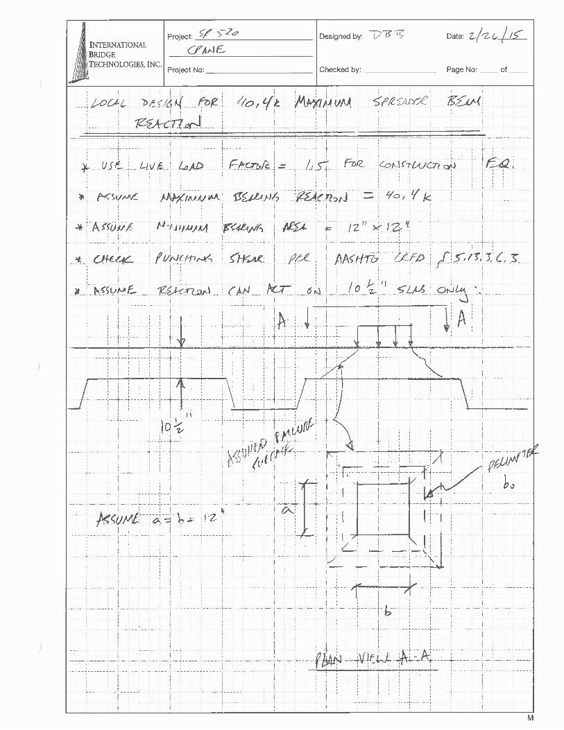
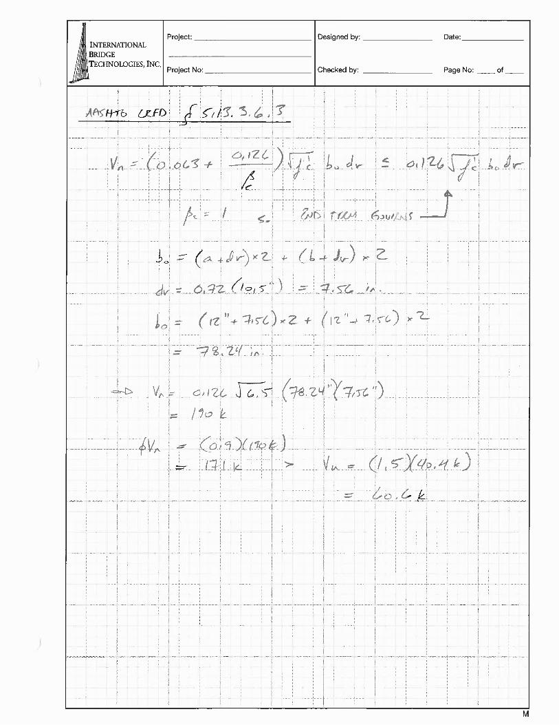
From: Sax, StephenTo: Kelley, Penny (ECY)Cc: [email protected]; Bullamore, Bryant; Wornell, GregSubject: SR 520 Floating Bridge Inspect 06-09-16.doc_BWT NOTESDate: Thursday, June 23, 2016 4:08:25 PMAttachments: SR 520 Floating Bridge Inspect 06-09-16.doc_BWT NOTES.doc
Penny, I distributed the inspection report you drafted for review and comment. There was some information in the text areas you highlighted that required additional clarification or correction. These have been incorporated into track changes in the attached version. If you have any questions please contact me. Thanks for providing us an opportunity to review the document and please send us the final version for our records. Stephen
Stephen J. SaxEnvironmental Compliance Team LeadSR 520, I-5 to Medina: Stage 1 Evergreen Point Floating Bridge and LandingsWashington State Department of Transportation3015 - 112th Ave NE, Suite 100, Bellevue, WA 98004-8001425.576.7133 0ffice 206-713-9783 CellP Please Reduce, Reuse, Recycle, Rethink
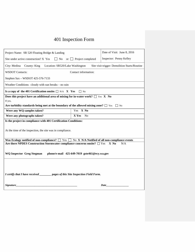
401 Inspection Form
Project Name: SR 520 Floating Bridge & Landing
Site under active construction? X Yes No or Project completed
Date of Visit: June 8, 2016
Inspector: Penny Kelley
City: Medina County: King Location: SR520/Lake Washington Site visit trigger: Demolition Starts/Routine
WSDOT Contacts: Contact information:
Stephen Sax – WSDOT 425-576-7133
Weather Conditions: cloudy with sun breaks – no rain
Is a copy of the 401 Certification onsite: N/A X Yes No
Does this project have an additional area of mixing for in-water work? Yes X No
If yes,
Are turbidity standards being met at the boundary of the allowed mixing zone? Yes No
Were any WQ samples taken? Yes X No
Were any photographs taken? X Yes No
Is the project in compliance with 401 Certification Conditions:
At the time of the inspection, the site was in compliance.
Was Ecology notified of non-compliance? Yes No X N/A Notified of all non-compliance events Are there NPDES Construction Stormwater compliance concerns onsite? Yes X No N/A WQ Inspector Greg Stegman phone/e-mail 425-649-7019 [email protected]
I certify that I have received ________ pages of this Site Inspection Field Form.
Signature______________________________________________ Date_________________
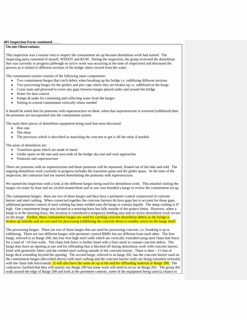
401 Inspection Form continued…….
On-site Observations: This inspection was a routine visit to inspect the containment set up because demolition work had started. The inspecting party consisted of myself, WSDOT and KGM. During the inspection, the group reviewed the demolition that was currently in progress (although no active work was occurring at the time of inspection) and discussed the process as it related to different sections of the bridge when viewed from the water. The containment system consists of the following main components:
• Two containment barges that catch debris when breaking up the bridge i.e. rubblizing different sections • Two processing barges for the girders and pier caps where they are broken up i.e. rubblized on the barge • Crane mats and plywood to cover any gaps between barges placed under and around the bridge • Water for dust control • Pumps & tanks for containing and collecting water from the barges • Netting to extend containment vertically where needed
It should be noted that for pontoons with superstructure on them, when that superstructure is removed (rubblized) then the pontoons are incorporated into the containment system. The main three pieces of demolition equipment being used that were discussed:
• Hoe ram • The shear • The processor which is described as munching the concrete to get it off the rebar if needed.
The areas of demolition are:
• Transition spans which are made of metal • Girder spans on the east and west ends of the bridge aka east and west approaches • Pontoons and superstructure
There are pontoons with no superstructure and those pontoons will be separated, floated out of the lake and sold. The ongoing demolition work currently in progress includes the transition spans and the girder spans. At the time of the inspection, the contractor had not started demolishing the pontoons with superstructure. We started the inspection with a look at the different barges being used for demolition work. This entailed visiting the barges via water by boat and we circled around them and in one case boarded a barge to review the containment set up. The containment barges: there are two of these barges and they have a perimeter control constructed of concrete barrier and steel curbing. When connected together the concrete barriers do have gaps but to account for those gaps, additional perimeter control of steel curbing has been welded onto the barge to contain liquids. The steep curbing is 4” high. One containment barge was located at a mooring buoy but falls outside of the project limits. However, when a barge is at the mooring buoy, this location is considered a temporary holding area and no active demolition work occurs on the barge. Further, these containment barges are used for catching concrete demolition debris as the bridge is broken up initially and are not used for processing (rubblizing the concrete down to smaller sizes) on the barge itself. The processing barges: There are two of these barges that are used for processing concrete, i.e. breaking it up or rubblizing. There are two different barges with perimeter control BMPs but are different from each other. The first barge, referred to as Barge 200, has four foot high steel walls which are vertically extended using steel chain link fence for a total of ~10 foot walls. The chain link fence is further lined with a finer mesh to contain concrete debris. The barge does have an opening at one end for offloading that is blocked off during demolition work with concrete barrier, lined with geotextile fabric and the welded steel curbing outside of the concrete barrier. There is then ~ 15 feet of barge deck extending beyond the opening. The second barge, referred to as barge 202, has the concrete barrier used on the containment barges (described above) with steel curbing and the concrete barrier walls are being extended vertically with the chain link fence/mesh. It will also have the same set up at the end for offloading material as Barge 200. The contractor clarified that they will mainly use Barge 200 but some work will need to occur on Barge 202. The group did walk around the edge of Barge 200 and look at the perimeter controls, some of the equipment being used (a chance to
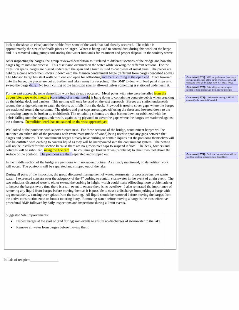
look at the shear up close) and the rubble from some of the work that had already occurred. The rubble is approximately the size of softballs pieces or larger. Water is being used to control dust during this work on the barge and it is removed using pumps and storing that water into tanks for treatment and proper disposal in the sanitary sewer. After inspecting the barges, the group reviewed demolition as it related to different sections of the bridge and how the barges figure into that process. This discussion occurred on the water while viewing the different sections. For the transition spans, barges are placed underneath the span and a torch is used to cut pieces of metal truss. The pieces are held by a crane which then lowers it down onto the Manson containment barge (different from barges described above). The Manson barge has steel walls with one end open for offloading and metal curbing at the open end. Once lowered onto the barge, the pieces are cut up further and taken away for recycling. The BMP to deal with lead paint chips is to sweep the barge daily. No torch cutting of the transition span is allowed unless something is stationed underneath it. For the east approach, some demolition work has already occurred. Metal poles with wire were installed from the girders/pier caps which netting (consisting of a metal mesh) is hung down to contain the concrete debris when breaking up the bridge deck and barriers. This netting will only be used on the east approach. Barges are station underneath around the bridge columns to catch the debris as it falls from the deck. Plywood is used to cover gaps where the barges are stationed around the columns. The girders and pier caps are snipped off using the shear and lowered down to the processing barge to be broken up (rubblized). The remaining columns are then broken down or rubblized with the debris falling onto the barges underneath, again using plywood to cover the gaps where the barges are stationed against the columns. Demolition work has not started on the west approach yet. We looked at the pontoons with superstructure next. For these sections of the bridge, containment barges will be stationed on either side of the pontoons with crane mats (made of wood) being used to span any gaps between the barges and pontoons. The containment barges already have curbing to contain liquids but the pontoons themselves will also be outfitted with curbing to contain liquid as they will be incorporated into the containment system. The netting will not be installed for this section because there are no girders/pier caps to suspend it from. The deck, barriers and columns will be rubblized, using the hoe ram. The columns get broken down (rubblized) to about two feet above the surface of the pontoon. The pontoons are then separated and shipped out. In the middle section of the bridge are pontoons with no superstructure. As already mentioned, no demolition work will occur. The pontoons will be separated and shipped out of the lake. During all parts of the inspection, the group discussed management of water: stormwater or process/concrete waste water. I expressed concern over the adequacy of the 4” curbing to contain stormwater in the event of a rain event. The two solutions discussed were to either extend the curbing in height, which could make offloading more problematic or to inspect the barges every time there is a rain event to ensure there is no overflow. I also reiterated the importance of removing any liquid from barges before moving them as it is possible to cause a discharge from jerking a barge with tug too suddenly, causing over splash from the curbing. All liquid should be removed before moving the barges from the active construction zone or from a mooring buoy. Removing water before moving a barge is the most effective procedural BMP followed by daily inspections and inspections during all rain events. Suggested Site Improvements:
• Inspect barges at the start of (and during) rain events to ensure no discharges of stormwater to the lake.
• Remove all water from barges before moving them.
Initials of recipient________________
Comment [BT1]: M73 barge does not have metal curbing on the stern of the barge. The bow, port, and starboard sides of the barge have a 5’ metal fence.
Comment [BT2]: Paint chips are swept up as needed to keep them away from the barge edges.
Comment [BT3]: I believe the netting is HDPE. I can verify the material if needed.
Comment [BT4]: Both hoe ram and shear will be used for pontoon superstructure demolition.
From: [email protected]: Kelley, Penny (ECY)Subject: RE: Updated WQMPP item- Span 43 Deck Slab Removal PlanDate: Thursday, June 23, 2016 5:29:07 PMAttachments: image002.jpg
image003.jpg
I’ll forward this and hope for the best! Robert
Kiewit Logo
ROBERT BRENNER, MS, CEP, CPESC District Environmental Manager Kiewit Bridge & Marine 33455 6th Ave S, Federal Way, WA 98003 (253) 943-4094 Office (425) 577-2939 Cell kiewit.com
From: Kelley, Penny (ECY) [mailto:[email protected]] Sent: Thursday, June 23, 2016 5:28 PMTo: Robert.Brenner <[email protected]>; Stephen.Sax-PTR <[email protected]>Cc: [email protected]: RE: Updated WQMPP item- Span 43 Deck Slab Removal Plan Sweet – get it to me before I get in tomorrow and I will look at it first thing…
From: [email protected] [mailto:[email protected]] Sent: Thursday, June 23, 2016 5:26 PMTo: Kelley, Penny (ECY) <[email protected]>; [email protected]: [email protected]: RE: Updated WQMPP item- Span 43 Deck Slab Removal Plan Hi Penny, I forwarded your email to get you the figure and answers you requested. I get them back to you as soon as I have them. Thanks,Robert
Kiewit Logo
ROBERT BRENNER, MS, CEP, CPESC District Environmental Manager Kiewit Bridge & Marine 33455 6th Ave S, Federal Way, WA 98003 (253) 943-4094 Office (425) 577-2939 Cell kiewit.com
From: Kelley, Penny (ECY) [mailto:[email protected]] Sent: Thursday, June 23, 2016 5:24 PMTo: Stephen.Sax-PTR <[email protected]>Cc: Bullamore, Bryant <[email protected]>; Robert.Brenner <[email protected]>Subject: RE: Updated WQMPP item- Span 43 Deck Slab Removal Plan Hi Stephen, I think I misunderstood what was going to be sent as I thought there would be a write up, similar to what has been submitted in the past, that would be incorporated into the overall WQMPP. I would at least like a graphic of the tarp BMP (hand drawn is fine) showing the location of the low point and where the tanks on barge would sit. It does not have to be fancy – again hand drawn is fine, maybe onto a plan sheet that is a cross section of the bridge would work. Also, how will the crews access the low point and vacuum it out? Finally, what type of monitoring/inspections will be done? Will there be someone on site to inspect/watch the work and make sure there are no leaks or discharges? Will the tarp be inspected daily to make sure it is in good shape before work? I get in tomorrow at 9:30 and I will make it my priority to look at this plan first thing when I get in. Call me if you have questions! Also, I will be here until 5:30 Penny Kelley WSDOT LiaisonOffice: 360-407-7298Cell: [email protected]
From: Sax, Stephen [mailto:[email protected]] Sent: Thursday, June 23, 2016 3:27 PMTo: Kelley, Penny (ECY) <[email protected]>Cc: Bullamore, Bryant <[email protected]>; [email protected]: Updated WQMPP item- Span 43 Deck Slab Removal Plan Penny,
As we discussed earlier today, here is a description of information KGM has provided for the revised work activities associated with the Span 43 demolition and an attached graphic to update the WQMPP for WQC 9011. Our means and methods for removing the roadway deck on span 43 have changed slightly. Instead of breaking the deck out on this span we plan to saw cut the roadway deck into sections to be removed with a crane sitting on top of the span. To contain the saw cut process water we will have a crew vacuuming beside the saw from the top deck. We are also installing a 100’ x 100’ tarp spanning between Pier 43 and Pier 44. The Tarp will be fixed to guy wires running between the piles. We will have pumping and vacuuming gear at the low end of the tarp to transfer the water to the storage tanks on support barges. KGM would like to start this work ASAP so a quick review cycle on your end would be appreciated. WSDOT has discussed the demo method internally and BMPs KGM has proposed for protecting water quality. Based on my conversation with you last week, the text in the email below will need to be y incorporated into a revised WQMPP along the missing elements in the timeline you provided . However, we are hoping that because this work needs to be done quickly the incorporation of that text can be done at a later date. Please contact me if you have any questions. Stephen
Stephen J. SaxEnvironmental Compliance Team LeadSR 520, I-5 to Medina: Stage 1 Evergreen Point Floating Bridge and LandingsWashington State Department of Transportation3015 - 112th Ave NE, Suite 100, Bellevue, WA 98004-8001425.576.7133 0ffice 206-713-9783 CellP Please Reduce, Reuse, Recycle, Rethink
From: Kelley, Penny (ECY)To: "[email protected]"Cc: [email protected]; [email protected]; [email protected]: RE: Updated WQMPP item- Span 43 Deck Slab Removal PlanDate: Friday, June 24, 2016 10:32:00 AMAttachments: image001.jpg
Yes, that will work for me.
From: [email protected] [mailto:[email protected]] Sent: Friday, June 24, 2016 10:32 AMTo: Kelley, Penny (ECY) <[email protected]>Cc: [email protected]; [email protected]; [email protected]: Re: Updated WQMPP item- Span 43 Deck Slab Removal Plan I can work on that next week. I'm in the middle of an Ecology Hazwaste inspection right now. Will that work for you? Thanks for getting this done so fast!!! Best regards,Robert
Sent from my iPhone
On Jun 24, 2016, at 10:25 AM, Kelley, Penny (ECY) <[email protected]> wrote:
Hello Robert, Thanks for getting me the additional information so quickly. I have reviewed the graphic with text and it addressed my questions. I am approving the updates to the WQMPP. Please note that this graphic will need to be included in the WQMPP (as an appendix is fine) and I would like for you to refer to it in the write up. When do you expect to have a revised plan that incorporates this information? Penny Kelley WSDOT LiaisonOffice: 360-407-7298Cell: [email protected]
From: [email protected] [mailto:[email protected]] Sent: Friday, June 24, 2016 7:42 AMTo: Kelley, Penny (ECY) <[email protected]>; [email protected]; [email protected]: [email protected]: FW: Updated WQMPP item- Span 43 Deck Slab Removal Plan
Hi Penny, Please see the attached figure, which should answer your questions. If you have any other needs, please let me know. Best regards,Robert
Kiewit Logo
ROBERT BRENNER, MS, CEP, CPESC District Environmental Manager Kiewit Bridge & Marine 33455 6th Ave S, Federal Way, WA 98003 (253) 943-4094 Office (425) 577-2939 Cell kiewit.com
From: Ben Tornberg [mailto:[email protected]] Sent: Friday, June 24, 2016 7:37 AMTo: Robert.Brenner <[email protected]>Subject: RE: Updated WQMPP item- Span 43 Deck Slab Removal Plan Robert, Attached please find the sketch that should answers Penny’s questions. Regards, Ben TornbergKiewit/General/Manson, A Joint VentureSR 520 Evergreen Point Floating Bridge3015 112th Ave N.E., Bellevue, WA 98004Cell: 206-496-9407
From: [email protected] [mailto:[email protected]] Sent: Thursday, June 23, 2016 5:26 PMTo: Ben TornbergSubject: FW: Updated WQMPP item- Span 43 Deck Slab Removal Plan See below. Can you throw a figure together for Penny and answer her questions? Thanks,Robert
Kiewit Logo
ROBERT BRENNER, MS, CEP, CPESC District Environmental Manager Kiewit Bridge & Marine 33455 6th Ave S, Federal Way, WA 98003 (253) 943-4094 Office (425) 577-2939 Cell kiewit.com
From: Kelley, Penny (ECY) [mailto:[email protected]] Sent: Thursday, June 23, 2016 5:24 PMTo: Stephen.Sax-PTR <[email protected]>Cc: Bullamore, Bryant <[email protected]>; Robert.Brenner <[email protected]>Subject: RE: Updated WQMPP item- Span 43 Deck Slab Removal Plan Hi Stephen, I think I misunderstood what was going to be sent as I thought there would be a write up, similar to what has been submitted in the past, that would be incorporated into the overall WQMPP. I would at least like a graphic of the tarp BMP (hand drawn is fine) showing the location of the low point and where the tanks on barge would sit. It does not have to be fancy – again hand drawn is fine, maybe onto a plan sheet that is a cross section of the bridge would work. Also, how will the crews access the low point and vacuum it out? Finally, what type of monitoring/inspections will be done? Will there be someone on site to inspect/watch the work and make sure there are no leaks or discharges? Will the tarp be inspected daily to make sure it is in good shape before work? I get in tomorrow at 9:30 and I will make it my priority to look at this plan first thing when I get in. Call me if you have questions! Also, I will be here until 5:30 Penny Kelley WSDOT LiaisonOffice: 360-407-7298Cell: [email protected]
From: Sax, Stephen [mailto:[email protected]] Sent: Thursday, June 23, 2016 3:27 PMTo: Kelley, Penny (ECY) <[email protected]>Cc: Bullamore, Bryant <[email protected]>; [email protected]
Subject: Updated WQMPP item- Span 43 Deck Slab Removal Plan Penny, As we discussed earlier today, here is a description of information KGM has provided for the revised work activities associated with the Span 43 demolition and an attached graphic to update the WQMPP for WQC 9011. Our means and methods for removing the roadway deck on span 43 have changed slightly. Instead of breaking the deck out on this span we plan to saw cut the roadway deck into sections to be removed with a crane sitting on top of the span. To contain the saw cut process water we will have a crew vacuuming beside the saw from the top deck. We are also installing a 100’ x 100’ tarp spanning between Pier 43 and Pier 44. The Tarp will be fixed to guy wires running between the piles. We will have pumping and vacuuming gear at the low end of the tarp to transfer the water to the storage tanks on support barges. KGM would like to start this work ASAP so a quick review cycle on your end would be appreciated. WSDOT has discussed the demo method internally and BMPs KGM has proposed for protecting water quality. Based on my conversation with you last week, the text in the email below will need to be y incorporated into a revised WQMPP along the missing elements in the timeline you provided . However, we are hoping that because this work needs to be done quickly the incorporation of that text can be done at a later date. Please contact me if you have any questions. Stephen
Stephen J. SaxEnvironmental Compliance Team LeadSR 520, I-5 to Medina: Stage 1 Evergreen Point Floating Bridge and LandingsWashington State Department of Transportation3015 - 112th Ave NE, Suite 100, Bellevue, WA 98004-8001425.576.7133 0ffice 206-713-9783 CellP Please Reduce, Reuse, Recycle, Rethink
CONFIDENTIALITY NOTICEThis transmission is intended for the sole use of the individual and/or entity to whom it is addressed, and may contain information and/or attachments that are privileged, confidential and exempt from disclosure under applicable law. If the reader of this transmission is not the intended recipient, you are hereby notified that any disclosure, dissemination,

distribution, duplication or the taking of any action in reliance on the contents of this transmission by someone other than the intended addressee or its designated agent is strictly prohibited. If your receipt of this transmission is in error, please notify the sender by replying immediately to this transmission and destroying the transmission. For your protection, do not include Social Security numbers, passwords or other non-public and personal information in your email. Thank you. (MCCDiscl001)
<20160624072856125.pdf>
From: Kelley, Penny (ECY)To: "Sax, Stephen"Cc: [email protected]; Bullamore, Bryant; Wornell, GregSubject: RE: SR 520 Floating Bridge Inspect 06-09-16.doc -updated reportDate: Friday, June 24, 2016 1:40:00 PMAttachments: SR 520 Floating Bridge Inspect 06-09-16.doc
Hi Stephen, Thank you for reviewing the inspection report and providing clarifications. I have updated my inspection report accordingly and attached a clean/final version. Please let me know if you have any questions. Penny Kelley WSDOT LiaisonOffice: 360-407-7298Cell: [email protected]
From: Sax, Stephen [mailto:[email protected]] Sent: Thursday, June 23, 2016 4:08 PMTo: Kelley, Penny (ECY) <[email protected]>Cc: [email protected]; Bullamore, Bryant <[email protected]>; Wornell, Greg <[email protected]>Subject: SR 520 Floating Bridge Inspect 06-09-16.doc_BWT NOTES Penny, I distributed the inspection report you drafted for review and comment. There was some information in the text areas you highlighted that required additional clarification or correction. These have been incorporated into track changes in the attached version. If you have any questions please contact me. Thanks for providing us an opportunity to review the document and please send us the final version for our records. Stephen
Stephen J. SaxEnvironmental Compliance Team LeadSR 520, I-5 to Medina: Stage 1 Evergreen Point Floating Bridge and LandingsWashington State Department of Transportation3015 - 112th Ave NE, Suite 100, Bellevue, WA 98004-8001425.576.7133 0ffice 206-713-9783 CellP Please Reduce, Reuse, Recycle, Rethink

401 Inspection Form
Project Name: SR 520 Floating Bridge & Landing
Site under active construction? X Yes No or Project completed
Date of Visit: June 8, 2016
Inspector: Penny Kelley
City: Medina County: King Location: SR520/Lake Washington Site visit trigger: Demolition Starts/Routine
WSDOT Contacts: Contact information:
Stephen Sax – WSDOT 425-576-7133
Weather Conditions: cloudy with sun breaks – no rain
Is a copy of the 401 Certification onsite: N/A X Yes No
Does this project have an additional area of mixing for in-water work? Yes X No
If yes,
Are turbidity standards being met at the boundary of the allowed mixing zone? Yes No
Were any WQ samples taken? Yes X No
Were any photographs taken? X Yes No
Is the project in compliance with 401 Certification Conditions:
At the time of the inspection, the site was in compliance.
Was Ecology notified of non-compliance? Yes No X N/A Notified of all non-compliance events Are there NPDES Construction Stormwater compliance concerns onsite? Yes X No N/A WQ Inspector Greg Stegman phone/e-mail 425-649-7019 [email protected]
I certify that I have received ________ pages of this Site Inspection Field Form.
Signature______________________________________________ Date_________________
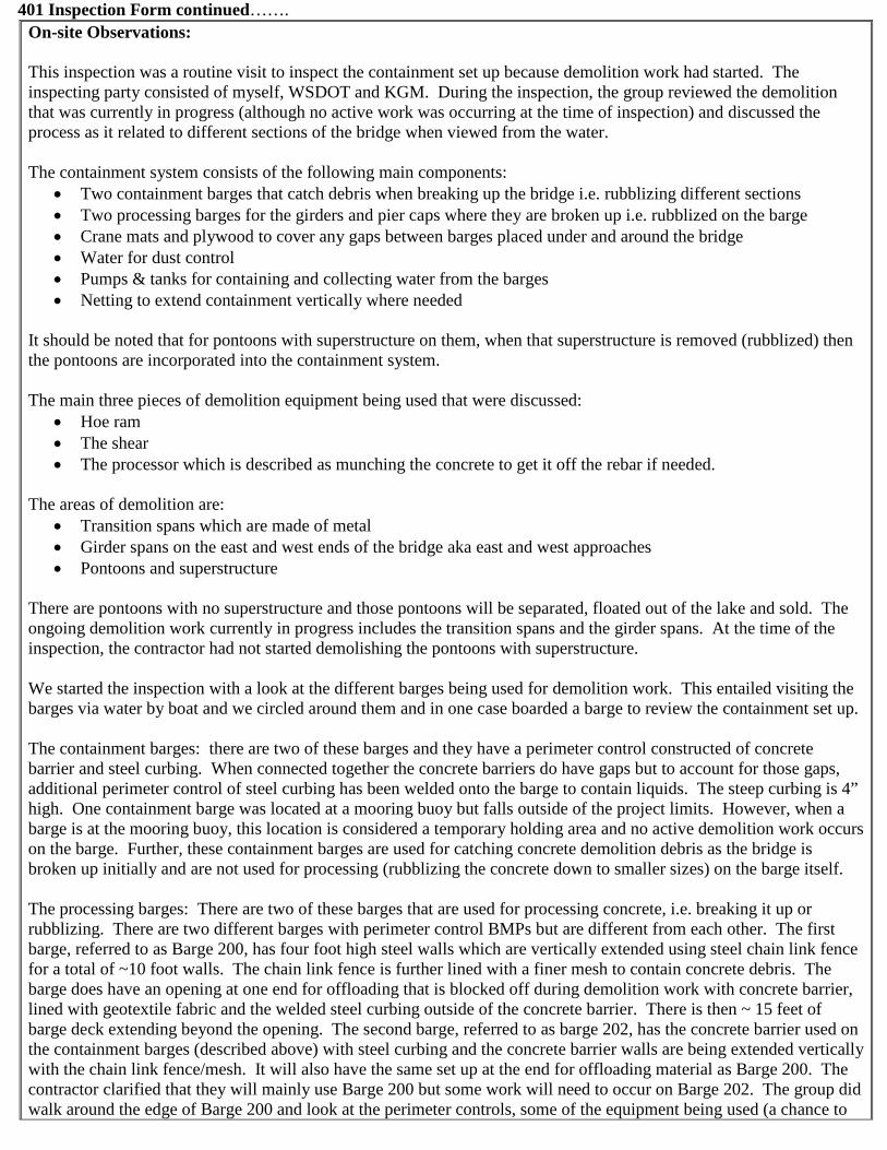
401 Inspection Form continued…….
On-site Observations: This inspection was a routine visit to inspect the containment set up because demolition work had started. The inspecting party consisted of myself, WSDOT and KGM. During the inspection, the group reviewed the demolition that was currently in progress (although no active work was occurring at the time of inspection) and discussed the process as it related to different sections of the bridge when viewed from the water. The containment system consists of the following main components:
• Two containment barges that catch debris when breaking up the bridge i.e. rubblizing different sections • Two processing barges for the girders and pier caps where they are broken up i.e. rubblized on the barge • Crane mats and plywood to cover any gaps between barges placed under and around the bridge • Water for dust control • Pumps & tanks for containing and collecting water from the barges • Netting to extend containment vertically where needed
It should be noted that for pontoons with superstructure on them, when that superstructure is removed (rubblized) then the pontoons are incorporated into the containment system. The main three pieces of demolition equipment being used that were discussed:
• Hoe ram • The shear • The processor which is described as munching the concrete to get it off the rebar if needed.
The areas of demolition are:
• Transition spans which are made of metal • Girder spans on the east and west ends of the bridge aka east and west approaches • Pontoons and superstructure
There are pontoons with no superstructure and those pontoons will be separated, floated out of the lake and sold. The ongoing demolition work currently in progress includes the transition spans and the girder spans. At the time of the inspection, the contractor had not started demolishing the pontoons with superstructure. We started the inspection with a look at the different barges being used for demolition work. This entailed visiting the barges via water by boat and we circled around them and in one case boarded a barge to review the containment set up. The containment barges: there are two of these barges and they have a perimeter control constructed of concrete barrier and steel curbing. When connected together the concrete barriers do have gaps but to account for those gaps, additional perimeter control of steel curbing has been welded onto the barge to contain liquids. The steep curbing is 4” high. One containment barge was located at a mooring buoy but falls outside of the project limits. However, when a barge is at the mooring buoy, this location is considered a temporary holding area and no active demolition work occurs on the barge. Further, these containment barges are used for catching concrete demolition debris as the bridge is broken up initially and are not used for processing (rubblizing the concrete down to smaller sizes) on the barge itself. The processing barges: There are two of these barges that are used for processing concrete, i.e. breaking it up or rubblizing. There are two different barges with perimeter control BMPs but are different from each other. The first barge, referred to as Barge 200, has four foot high steel walls which are vertically extended using steel chain link fence for a total of ~10 foot walls. The chain link fence is further lined with a finer mesh to contain concrete debris. The barge does have an opening at one end for offloading that is blocked off during demolition work with concrete barrier, lined with geotextile fabric and the welded steel curbing outside of the concrete barrier. There is then ~ 15 feet of barge deck extending beyond the opening. The second barge, referred to as barge 202, has the concrete barrier used on the containment barges (described above) with steel curbing and the concrete barrier walls are being extended vertically with the chain link fence/mesh. It will also have the same set up at the end for offloading material as Barge 200. The contractor clarified that they will mainly use Barge 200 but some work will need to occur on Barge 202. The group did walk around the edge of Barge 200 and look at the perimeter controls, some of the equipment being used (a chance to
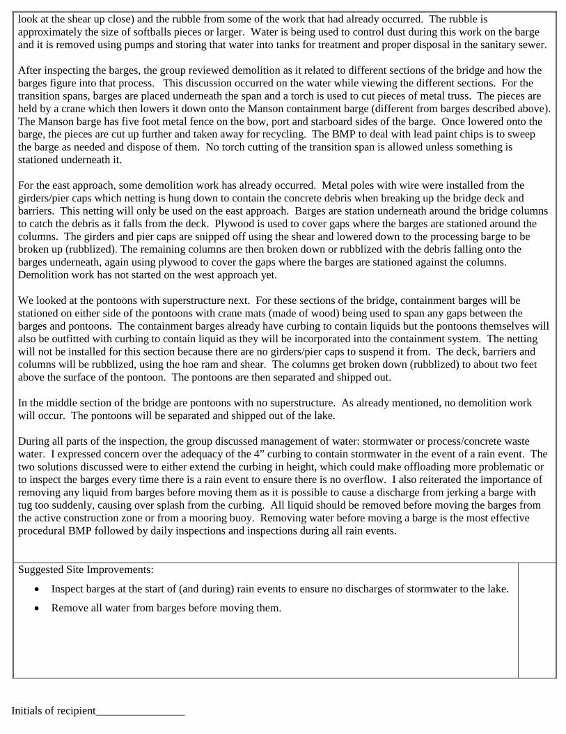
look at the shear up close) and the rubble from some of the work that had already occurred. The rubble is approximately the size of softballs pieces or larger. Water is being used to control dust during this work on the barge and it is removed using pumps and storing that water into tanks for treatment and proper disposal in the sanitary sewer. After inspecting the barges, the group reviewed demolition as it related to different sections of the bridge and how the barges figure into that process. This discussion occurred on the water while viewing the different sections. For the transition spans, barges are placed underneath the span and a torch is used to cut pieces of metal truss. The pieces are held by a crane which then lowers it down onto the Manson containment barge (different from barges described above). The Manson barge has five foot metal fence on the bow, port and starboard sides of the barge. Once lowered onto the barge, the pieces are cut up further and taken away for recycling. The BMP to deal with lead paint chips is to sweep the barge as needed and dispose of them. No torch cutting of the transition span is allowed unless something is stationed underneath it. For the east approach, some demolition work has already occurred. Metal poles with wire were installed from the girders/pier caps which netting is hung down to contain the concrete debris when breaking up the bridge deck and barriers. This netting will only be used on the east approach. Barges are station underneath around the bridge columns to catch the debris as it falls from the deck. Plywood is used to cover gaps where the barges are stationed around the columns. The girders and pier caps are snipped off using the shear and lowered down to the processing barge to be broken up (rubblized). The remaining columns are then broken down or rubblized with the debris falling onto the barges underneath, again using plywood to cover the gaps where the barges are stationed against the columns. Demolition work has not started on the west approach yet. We looked at the pontoons with superstructure next. For these sections of the bridge, containment barges will be stationed on either side of the pontoons with crane mats (made of wood) being used to span any gaps between the barges and pontoons. The containment barges already have curbing to contain liquids but the pontoons themselves will also be outfitted with curbing to contain liquid as they will be incorporated into the containment system. The netting will not be installed for this section because there are no girders/pier caps to suspend it from. The deck, barriers and columns will be rubblized, using the hoe ram and shear. The columns get broken down (rubblized) to about two feet above the surface of the pontoon. The pontoons are then separated and shipped out. In the middle section of the bridge are pontoons with no superstructure. As already mentioned, no demolition work will occur. The pontoons will be separated and shipped out of the lake. During all parts of the inspection, the group discussed management of water: stormwater or process/concrete waste water. I expressed concern over the adequacy of the 4” curbing to contain stormwater in the event of a rain event. The two solutions discussed were to either extend the curbing in height, which could make offloading more problematic or to inspect the barges every time there is a rain event to ensure there is no overflow. I also reiterated the importance of removing any liquid from barges before moving them as it is possible to cause a discharge from jerking a barge with tug too suddenly, causing over splash from the curbing. All liquid should be removed before moving the barges from the active construction zone or from a mooring buoy. Removing water before moving a barge is the most effective procedural BMP followed by daily inspections and inspections during all rain events. Suggested Site Improvements:
• Inspect barges at the start of (and during) rain events to ensure no discharges of stormwater to the lake.
• Remove all water from barges before moving them.
Initials of recipient________________
From: Kelley, Penny (ECY)To: "[email protected]"Cc: [email protected]; [email protected]; "[email protected]"Subject: FW: Updated WQMPP item- Span 43 Deck Slab Removal PlanDate: Friday, June 24, 2016 10:25:00 AMAttachments: image001.jpg
20160624072856125.pdf
Hello Robert, Thanks for getting me the additional information so quickly. I have reviewed the graphic with text and it addressed my questions. I am approving the updates to the WQMPP. Please note that this graphic will need to be included in the WQMPP (as an appendix is fine) and I would like for you to refer to it in the write up. When do you expect to have a revised plan that incorporates this information? Penny Kelley WSDOT LiaisonOffice: 360-407-7298Cell: [email protected]
From: [email protected] [mailto:[email protected]] Sent: Friday, June 24, 2016 7:42 AMTo: Kelley, Penny (ECY) <[email protected]>; [email protected]; [email protected]: [email protected]: FW: Updated WQMPP item- Span 43 Deck Slab Removal Plan Hi Penny, Please see the attached figure, which should answer your questions. If you have any other needs, please let me know. Best regards,Robert
Kiewit Logo
ROBERT BRENNER, MS, CEP, CPESC District Environmental Manager Kiewit Bridge & Marine 33455 6th Ave S, Federal Way, WA 98003 (253) 943-4094 Office (425) 577-2939 Cell kiewit.com
From: Ben Tornberg [mailto:[email protected]] Sent: Friday, June 24, 2016 7:37 AMTo: Robert.Brenner <[email protected]>Subject: RE: Updated WQMPP item- Span 43 Deck Slab Removal Plan Robert, Attached please find the sketch that should answers Penny’s questions. Regards, Ben TornbergKiewit/General/Manson, A Joint VentureSR 520 Evergreen Point Floating Bridge3015 112th Ave N.E., Bellevue, WA 98004Cell: 206-496-9407
From: [email protected] [mailto:[email protected]] Sent: Thursday, June 23, 2016 5:26 PMTo: Ben TornbergSubject: FW: Updated WQMPP item- Span 43 Deck Slab Removal Plan See below. Can you throw a figure together for Penny and answer her questions? Thanks,Robert
Kiewit Logo
ROBERT BRENNER, MS, CEP, CPESC District Environmental Manager Kiewit Bridge & Marine 33455 6th Ave S, Federal Way, WA 98003 (253) 943-4094 Office (425) 577-2939 Cell kiewit.com
From: Kelley, Penny (ECY) [mailto:[email protected]] Sent: Thursday, June 23, 2016 5:24 PMTo: Stephen.Sax-PTR <[email protected]>Cc: Bullamore, Bryant <[email protected]>; Robert.Brenner <[email protected]>Subject: RE: Updated WQMPP item- Span 43 Deck Slab Removal Plan Hi Stephen,
I think I misunderstood what was going to be sent as I thought there would be a write up, similar to what has been submitted in the past, that would be incorporated into the overall WQMPP. I would at least like a graphic of the tarp BMP (hand drawn is fine) showing the location of the low point and where the tanks on barge would sit. It does not have to be fancy – again hand drawn is fine, maybe onto a plan sheet that is a cross section of the bridge would work. Also, how will the crews access the low point and vacuum it out? Finally, what type of monitoring/inspections will be done? Will there be someone on site to inspect/watch the work and make sure there are no leaks or discharges? Will the tarp be inspected daily to make sure it is in good shape before work? I get in tomorrow at 9:30 and I will make it my priority to look at this plan first thing when I get in. Call me if you have questions! Also, I will be here until 5:30 Penny Kelley WSDOT LiaisonOffice: 360-407-7298Cell: [email protected]
From: Sax, Stephen [mailto:[email protected]] Sent: Thursday, June 23, 2016 3:27 PMTo: Kelley, Penny (ECY) <[email protected]>Cc: Bullamore, Bryant <[email protected]>; [email protected]: Updated WQMPP item- Span 43 Deck Slab Removal Plan Penny, As we discussed earlier today, here is a description of information KGM has provided for the revised work activities associated with the Span 43 demolition and an attached graphic to update the WQMPP for WQC 9011. Our means and methods for removing the roadway deck on span 43 have changed slightly. Instead of breaking the deck out on this span we plan to saw cut the roadway deck into sections to be removed with a crane sitting on top of the span. To contain the saw cut process water we will have a crew vacuuming beside the saw from the top deck. We are also installing a 100’ x 100’ tarp spanning between Pier 43 and Pier 44. The Tarp will be fixed to guy wires running between the piles. We will have pumping and vacuuming gear at the low end of the tarp to transfer the water to the storage tanks on support barges. KGM would like to start this work ASAP so a quick review cycle on your end would be appreciated. WSDOT has discussed the demo method internally and BMPs KGM has proposed for protecting water quality. Based on my conversation with you last week, the text in the email below will need to be y incorporated into a revised WQMPP along the missing elements in the timeline you provided . However, we are hoping that because this work needs to be done quickly the incorporation of that
text can be done at a later date. Please contact me if you have any questions. Stephen
Stephen J. SaxEnvironmental Compliance Team LeadSR 520, I-5 to Medina: Stage 1 Evergreen Point Floating Bridge and LandingsWashington State Department of Transportation3015 - 112th Ave NE, Suite 100, Bellevue, WA 98004-8001425.576.7133 0ffice 206-713-9783 CellP Please Reduce, Reuse, Recycle, Rethink
CONFIDENTIALITY NOTICEThis transmission is intended for the sole use of the individual and/or entity to whom it is addressed, and may contain information and/or attachments that are privileged, confidential and exempt from disclosure under applicable law. If the reader of this transmission is not the intended recipient, you are hereby notified that any disclosure, dissemination, distribution, duplication or the taking of any action in reliance on the contents of this transmission by someone other than the intended addressee or its designated agent is strictly prohibited. If your receipt of this transmission is in error, please notify the sender by replying immediately to this transmission and destroying the transmission. For your protection, do not include Social Security numbers, passwords or other non-public and personal information in your email. Thank you. (MCCDiscl001)

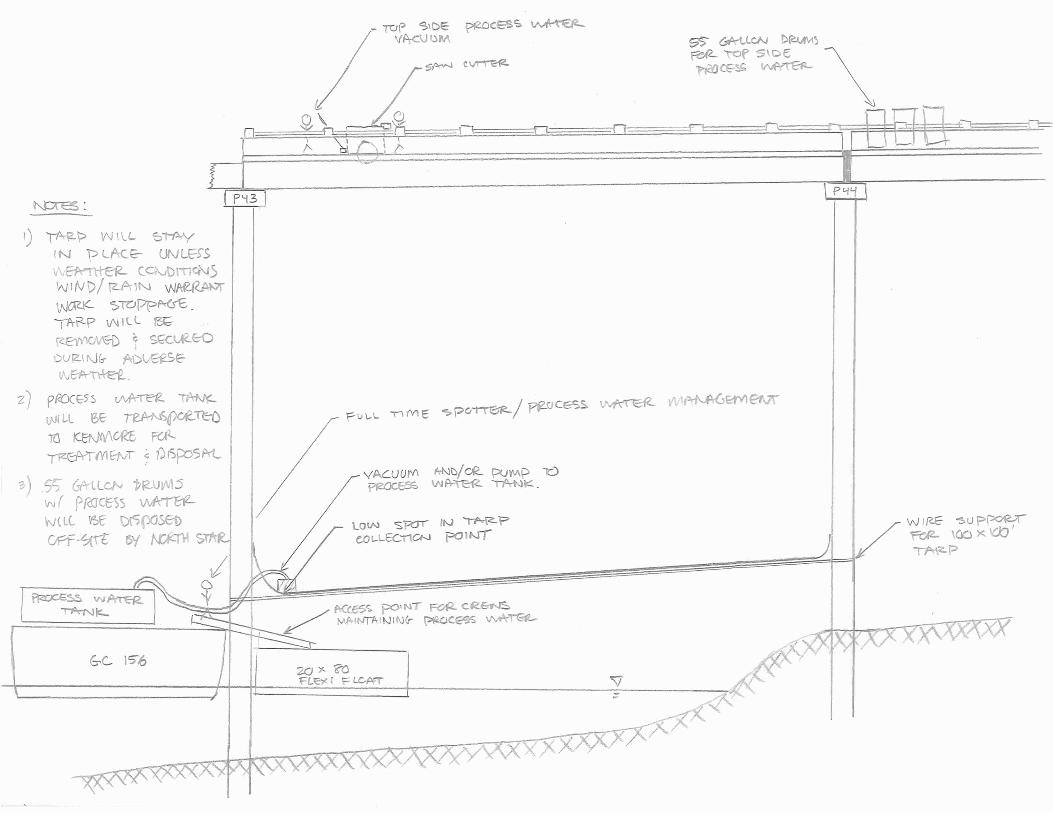
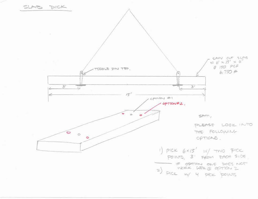
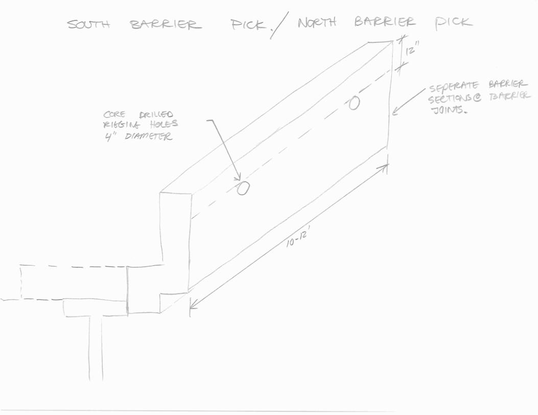
From: Sax, StephenTo: Boyd, Robyn; Bullamore, Bryant; MacDonald, Chris (Consultant); Wornell, Greg; [email protected]: Kucharski, Margaret; Kelley, Penny (ECY)Subject: Updates from PennyDate: Friday, June 26, 2015 11:03:37 AM
Hi all, I was able to connect with Penny Kelly before leaving to get an update on a couple of items. Bridge Demo Penny is planning on reviewing the revisions that were sent to her in the next few weeks and
is tentatively scheduled to have the document back by July 22nd. Please note that this date could be impacted by the potential layoff of state employees that would go into effect on July
1st. 6/17 ECAPPenny had just returned from vacation and did not have an opportunity to review the ECAP report for the grout discharge that occurred on 6/17. We briefly discussed the incident. She may be contacting us for further discussion or actions. I also reminded her that any conversations regarding this ECAP will need to include WSDOT as we are the permit holder. Stephen
Stephen J. SaxEnvironmental Compliance Team LeadSR 520, I-5 to Medina: Stage 1 Evergreen Point Floating Bridge and LandingsWashington State Department of Transportation3015 - 112th Ave NE, Suite 100, Bellevue, WA 98004-8001425.576.7133 0ffice 206-713-9783 CellP Please Reduce, Reuse, Recycle, Rethink