Saunier Duval Clima, S.A. - Pièces de Rechange · Saunier Duval Clima, S.A. ENGLISH ... The fitter...
12
INSTALLATION MANUAL Saunier Duval Clima, S.A. ENGLISH Safety Regulations ....................................................................................................... 3 Indoor Unit Installation Dimensions................................................................................................................................................ 4 Unit Location ........................................................................................................................................ 5 - 6 Outdoor Unit Installation Location..................................................................................................................................................... 7 Pipe Lenght ............................................................................................................................................... 7 Dimensions ............................................................................................................................................... 8 Installation Details ................................................................................................................................ 8 - 9 Wiring Diagrams ......................................................................................................... 10 SDC/H 050 F SDC/H 065 F SDC/H 085 F SDC/H 105 F SDC/H 105T F SDC/H 120 M2F
Transcript of Saunier Duval Clima, S.A. - Pièces de Rechange · Saunier Duval Clima, S.A. ENGLISH ... The fitter...

INSTALLATION MANUAL
Saunier Duval Clima, S.A.
EN
GLI
SH
Safety Regulations .......................................................................................................3Indoor Unit Installation Dimensions................................................................................................................................................ 4 Unit Location ........................................................................................................................................ 5 - 6
Outdoor Unit Installation Location..................................................................................................................................................... 7 Pipe Lenght ............................................................................................................................................... 7 Dimensions ............................................................................................................................................... 8 Installation Details ................................................................................................................................ 8 - 9
Wiring Diagrams .........................................................................................................10
SDC/H 050 FSDC/H 065 FSDC/H 085 FSDC/H 105 F
SDC/H 105T FSDC/H 120 M2F


3
EN
GLI
SH
The installation shall be made by authorised personal only
1- SAFETY REGULATIONS
This unit should be installed and used in com-pliance of the following:
- Low Voltage Electrotechnical Regulations- Safety Regulations for Cooling Plants and Facilities- Pressure Vessel Regulations- Basic Building Standards- Technical Building Standards- Municipal Regulations
• Saunier Duval, along the lines of its continuos product quality improvement policy, reserves the rights to modify the specifications without previous notice.
• Saunier Duval cannot foresee all circumstances that could result in hazard potentials.
• This A.C. unit is designed exclusively for air conditio-ning. Do not use this unit for any other purposes like drying clothes, cooling foodstuff or any other heating or cooling purposes.
• No part of this manual can be copied without written permission.
• Should you have any queries, please contact your nearest Saunier Duval distributor.
• This A.C. unit has been designed for the operating tem-peratures specified below. Do not let it work outside said ranges.
SUMMER - OUTDOOR 0ºC Min. 43ºC Max. - INDOOR 19ºC Min. 32ºC Max.WINTER - OUTDOOR -5ºC Min. 24ºC Max. - INDOOR 15ºC Min. 27ºC Max.
IMPORTANT NOTES
EXTREME OPERATIONS CONDITIONS
• Do not allow the customer to fit the air conditioning unit. Installation of the unit must be carried out by either the local distributor or a specialist fitter. The fitter is respon-sible for any problems caused by a faulty installation.
• The installation instructions must be followed closely. A faulty installation can lead to water leaks, electrical discharges or fires.
• Do not use any coolant other than R22. The mixture of gases in the cooling cycle can lead to damage or impaired performance.
• Check that the mounting and fastening devices are sufficient to withstand the weight of the unit. If they are not, the unit may fall and cause an accident.
• Ensure that all fastening devices and accessories are used. Use of any items not shown can lead to water leaks, electrical discharges or fires.
• Carry out electrical connections in accordance with local regulations and the instructions laid down in the installation manual. Ensure that the proper cables have been used. If they have not, this may cause electrical discharges or fires.
• While connecting the outdoor unit, keep the cabling conduit rigid. Faulty cable fitting can cause overhea-ting, electrical discharges or fire at these connections.
• The system must always be earthed. If it is not, this may lead to electrical discharges.
• Do not fit units in places which may be affected by leaks of inflammable gas. If the gas is in circulation around the units, this may cause explosions.
• Place the drainage hose in a suitable position. An improperly fitted hose will force the water back to the room, thus damaging the furniture.
• This air conditioning system is for home use only. Do not use it for any unspecified applications: warehouses, foodstuff depots, animals, plants, precision machinery, works of art etc. These items may be damaged as a result.
• Use the voltage shown. If this is not used, it may cause a fire or other problems.
4
EN
GLI
SH
Decide the mounting position together with the customer as follows:
1. INDOOR UNIT
- Install the unit where the drain pipe can be easily installed.- Take servicing, etc. into consideration and leave the spaces for the aftersale service.
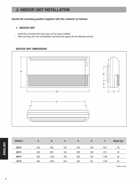
INDOOR UNIT DIMENSIONS
2- INDOOR UNIT INSTALLATION
MODELS A B C D E F Weight (kg)
050 FI 645 955 199 280 185 873 30
065 FI 645 955 199 280 185 873 30
090 FI 645 1.250 199 280 185 1.168 40
105 FI 645 1.600 245 300 80 1.470 63
Units in mm.
B
C D
E
F
G

5
EN
GLI
SH
2- INDOOR UNIT INSTALLATION
2- INSTALLATION PROCEDURE
1- PREPARING INDOOR UNIT INSTALLATION
Remove the intake grille and side cover(s) by remo-ving the tapping screws.
2- INDOOR UNIT INSTALLATION
A. FLOOR INSTALLATION
1. DRILLING FOR PIPING
Select piping and drain direction. The piping and drain can be made in two directions.
- The drain hose can be connected to the drain port either left or right side.
2. INSTALLING DRAIN HOSE
Insert the drain hose into the drain port, then secure the drain hose with a nylon fastener.
- When the direction are selected, drill 4” (100 mm) dia. hole on the wall so that the hole is tilted downward toward the outdoor for smooth water flow. When the pipe is led out from the rear, make a hole in Fig. 7 at the position shown.
Wrap the insulation around the drain hose connection.
Be sure to arrange the drain hose so that it is levelled lower than the drain port of the indoor unit.
- Do not install the unit so that the drain hose side is too high. Height A should be less than 5.
6
EN
GLI
SH
4. INSTALLING INDOOR UNIT Reset the bolts
as shown below.
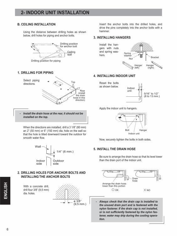
2- INDOOR UNIT INSTALLATION
When the directions are installed, drill a 3 1/8” (80 mm) an 2” (50 mm) or 6” (150 mm) dia. hole on the wall so that the hole is tilted downward toward the outdoor for smooth water flow.
B. CEILING INSTALLATION
Using the distance between drilling holes as shown below, drill holes for piping and anchor bolts.
1. DRILLING FOR PIPING
Select piping directions.
- Install the drain hose at the rear, it should not be installed on the top.
2. DRILLING HOLES FOR ANCHOR BOLTS AND INSTALLING THE ANCHOR BOLTS
With a concrete drill, drill four 3/8” (9,5 mm) dia. holes.
Insert the anchor bolts into the drilled holes, and drive the pins completely into the anchor bolts with a hammer.
3. INSTALLING HANGERS Install the han-
gers with nuts and spring was-hers.
Apply the indoor unit to hangers.
Now, securely tighten the bolts in both sides.
5. INSTALL THE DRAIN HOSE
Be sure to arrange the drain hose so that its level lower than the drain port of the indoor unit.
- Always check that the drain cap is installed to the unused drain port and is fastened with the nylon fastener. If the drain cap is not installed, or is not sufficiently fastened by the nylon fas-tener, water may drip during the cooling opera-tion.
7
EN
GLI
SH
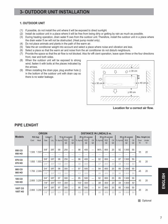
PIPE LENGHT
3- OUTDOOR UNIT INSTALLATION
1. OUTDOOR UNIT
(1) If possible, do not install the unit where it will be exposed to direct sunlight.(2) Install de outdoor unit in a place where it will be free from being dirty or getting by rain as much as possible.(3) During heating operation, drain water fl ows from the outdoor unit. Therefore, install the outdoor unit in a place where
the drain water fl ow will not be obstructed. (Heat pump model only).(4) Do not place animals and plants in the path of the warm air.(5) Take the air conditioner weight into account and select a place where noise and vibration are less.(6) Select a place so that the warm air and noise from the air conditioner do not disturb neighbours.(7) Provide the space so that the air flow is not blocked. Also for effi cient operation, leave open three or the four directions
front, rear and both sides.(8) When the outdoor unit will be exposed to strong
wind, fasten it with bolts at the places indicated by the arrows.
(9) When installing the drain pipe, plug another hole () in the bottom of the outdoor unit with drain cap so there is no water leakage.
ORIGIN DISTANCE IN LINEALS m. Models R22 (kg) Lines(‘‘) 15 m (4 curves) 20 m (6 curves) 30 m (8 curves) 50 m (6 curves) Max. Height (m)
Cool Heat Gas Líq. % Aprox. R22 Oil % Aprox. R22 Oil % Aprox. R22 Oil % Aprox. R22 Oil Over Under (g) (g) (g) (g) (g) (g) (g) (g) IU IU
050 CO 1.500 1.500
5/8” 3/8” 99 250 --- 98 400 --- 96% 800 20 92 1.500 50 45 20
050 HO --- --- --- --- --- --- --- --- --- --- --- --- --- ---
070 CO 1.850 1.850
5/8” 3/8” 98 250 --- 96 400 --- 92 800 --- 87 1.500 50 45 20
070 HO 3/4” 3/8” 100 300 --- 99 500 --- 97 800 20 94 1.500 50
085 CO 1.700 2.000
3/4” 3/8” 98 300 --- 97 500 --- 94 800 20 89 1.500 50 45 20
085 HO 7/8” 3/8” 102 300 --- 101 500 --- 99 900 20 96 1.600 50
105 CO 2.800 3.200
3/4” 3/8” 97 300 --- 95 500 --- 92 800 20 85 1.500 50 45 20
105 HO 7/8” 3/8” 101 300 --- 100 500 --- 98 900 20 94 1.600 50
105T CO 2.800 3.200
3/4” 3/8” 97 300 --- 95 500 --- 91 800 20 85 1.500 50 45 20
105T HO 7/8” 3/8” 101 300 --- 100 500 --- 98 900 20 94 1.600 50
Optional
?!41!dn
?!71!dn
?!41!dn
?!51!dn
Location for a correct air flow.

8
EN
GLI
SH
2- OUTDOOR UNIT INSTALLATION
- Set the unit on a strong stand, install protective rubber pieces under it.
- Do not install the unit directly on the ground, because it will cause trouble.
- Install the unit where it will not be tilted by more than 5º.
Dimensiones de las Unidades Exteriores
Uni
ts in
mm
.3- OUTDOOR UNIT INSTALLATION
3. CHECKING THE PIPE CONNECTIONS FOR GAS LEAKING
- For both the indoor and outdoor unit sides, check the joints for gas leaking by the use of a gas leakage detec-tor without fail when the pipes are connected.
4. HEAT INSULATION ON THE PIPE JOINTS
- Put coupler heat insulator on the joints.
AIR PURGE
- Close the high pressure side valve fully.- Check if the piping connections are secure.- Check that the stems of both 3- way valves are closed
fully.- Connect the gauge manifold service hose to the char-
ging port of the 3- way valve (side with the projection of pushing in the valve core).
- Open the low pressure side valve of the gauge mani-fold fully.
- Operate the vacuum pump and start pump down.- Pump down the system for at least 15 minutes, then
check if the compound pressure gauge reads - 100kPa (- 76 cm Hg, -1bar)
- At the end of pump down, close the low pressure side gauge of the gauge manifold fully and stop the vacuum pump.
- Slowly loosen the valve stem of the 3- way valve. When the compound pressure gauge reading reaches 1- 2 kg/ cm2, retighten the valve stem and disconnect the service hose from the 3- way valve charging port.
(If the stem of the 3- way valve is opened fully before the service hose is disconnected, it may be difficult to disconnect the service hose.)

9
EN
GLI
SH
ADDITIONAL CHARGE
- Refrigerant suitable for a piping length of 10 m. Is char-ged in the indoor unit at the factory.
- When the piping is longer than 10 m., additional char-ging is necessary.
3- OUTDOOR UNIT INSTALLATION
WARNING!(1) When moving and installing the air conditioner,
do not mix gas other than the specifi ed refrige-rant (R-22) inside the refrigerant cycle.
(2) When adding refrigerant, add the refrigerant from the charging port at the completion of work.
5- GAS LEAKAGE INSPECTION
WARNING!- After connecting the piping, check the joints for gas leakage with gas leak detector.
6- POWER
(1) The rate voltage of this product is monophase (230V/1Ph/50 Hz) / triphase (400V/3Ph/50Hz).(2) Use a circuit breaker an receptacle matched to the
capacity of the room air conditioner.
(3) The circuit breaker is installed in the permanent wiring. Always use circuit that can trip all the poles of the wiring and has an isolation distance of at least 3 mm. between the contacts of each pole.
(4) Perform wiring work in accordance with standards so that the room air conditioner can be operated safely and positively.
7- ELECTRICAL WIRING
(1) Connect the connection cords fi rmly to the ter-minal block. Imperfect installation may cause a fi re.
(2) If the indoor unit connection cord (to the outdoor unit) and power supply are wired incorrectly, the air conditioner may be damaged.
(3) Always connect the ground wire.
- Fully open the valve stems of both 3- way valves using a hexagon wrench. (After the valve stem begins to turn, turn it with a torque of less than 2.9 N- m (30 kgf- cm) until its stop turning.)
- Firmly tighten both 3- way valves blank cap and the charging port cap.
10
EN
GLI
SH
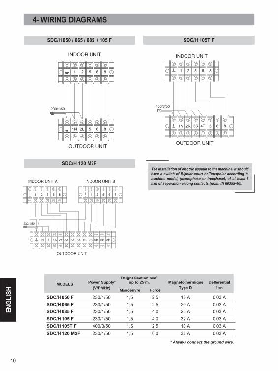
4- WIRING DIAGRAMS
* Always connect the ground wire.
Reight Section mm2 MODELS Power Supply* up to 25 m. Magnetothermique Defferential
(V/Ph/Hz) Manoeuvre Force Type D 1∆n
SDC/H 050 F 230/1/50 1,5 2,5 15 A 0,03 A
SDC/H 065 F 230/1/50 1,5 2,5 20 A 0,03 A
SDC/H 085 F 230/1/50 1,5 4,0 25 A 0,03 A
SDC/H 105 F 230/1/50 1,5 4,0 32 A 0,03 A
SDC/H 105T F 400/3/50 1,5 2,5 10 A 0,03 A
SDC/H 120 M2F 230/1/50 1,5 6,0 32 A 0,03 A
SDC/H 050 / 065 / 085 / 105 F SDC/H 105T F
SDC/H 120 M2F
The installation of electric assault to the machine, it should have a switch of Bipolar court or Tetrapolar according to machine model, (monophase or treephase), of at least 3 mm of separation among contacts (norm IN 60355-40).

www.saunierduval.es
XT2
2030
6/V
01 -
9001
872
Sau
nier
Duv
al s
e re
serv
a el
der
echo
de
intro
duci
r mod
ifica
cion
es s
in p
revi
o av
iso