SAM PDR1 SAM LGS Mechanical Design A. Montane, A. Tokovinin, H. Ochoa SAM LGS Preliminary Design...
26
SAM PDR 1 SAM SAM LGS LGS Mechanical Mechanical Design Design A. Montane, A. Tokovinin, H. Ochoa SAM LGS Preliminary Design Review September 2007, La Serena
-
Upload
mavis-garrett -
Category
Documents
-
view
215 -
download
1
Transcript of SAM PDR1 SAM LGS Mechanical Design A. Montane, A. Tokovinin, H. Ochoa SAM LGS Preliminary Design...
SAM PDR 1
SAMSAM LGSLGSMechanical Mechanical
DesignDesign
A. Montane, A. Tokovinin, H. Ochoa
SAM LGS Preliminary Design Review September 2007, La Serena
SAM PDR 2
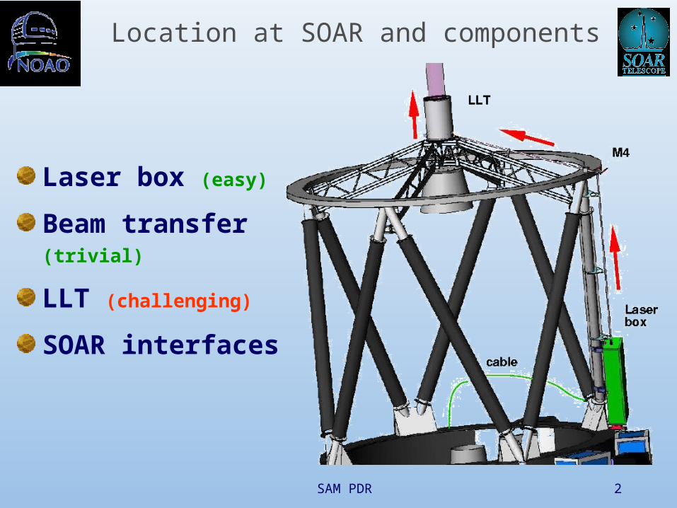
Location at SOAR and components
Laser box (easy)
Beam transfer (trivial)
LLT (challenging)
SOAR interfaces
SAM PDR 3
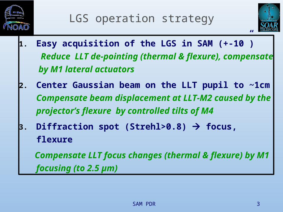
LGS operation strategy
1. Easy acquisition of the LGS in SAM (+-10”)
Reduce LLT de-pointing (thermal & flexure),
compensate by M1 lateral actuators
2. Center Gaussian beam on the LLT pupil to ~1cm
Compensate beam displacement at LLT-M2 caused
by the projector’s flexure by controlled tilts of M4
3. Diffraction spot (Strehl>0.8) focus, flexure
Compensate LLT focus changes (thermal & flexure)
by M1 focusing (to 2.5 µm)

SAM PDR 4
Laser box (1): inside
UV laser: 813x127x86mm, 14.5kg, 15..35 C
Blue alignment laser
Optical elements (beam expander, compensator, mirrors, …)
Air-tight, thermal stabilization and insulation
We know what’s inside, but no detailed design yet

SAM PDR 5
Laser box (2): interface
Box mass ~60kg
Thermal insulation
Tilt adjustment
SAM PDR 6
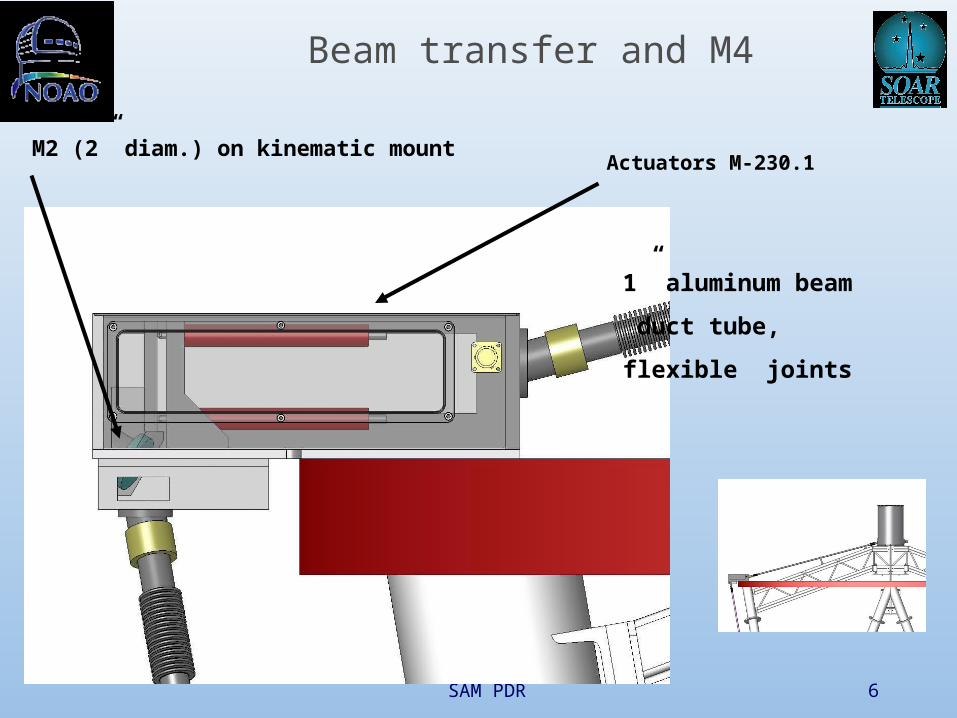
Beam transfer and M4
M2 (2” diam.) on kinematic mount
1” aluminum beam
duct tube,
flexible joints
Actuators M-230.1

SAM PDR 7
Laser Launch Telescope (LLT)
D=0.3m, F=0.5m primary mirror (M1): 1” = 2.5 µmD=15mm, F=15mm secondary (M2)
Low total mass (<8kg initially), L<700mm
Blind pointing to SOAR axis within 10” (goal)
Actively correct pointing (slowly) to 0.2” ( 0.5 m)
Focus from 7km to infinity (in temp. range -5..+25 C),
accuracy 2.5 m
Protection from dust and wind
Alignment and control tools
Requirements:

SAM PDR 8
LLT overview

SAM PDR 9
LLT: primary mirror
Material : Aluminum 6061 T6
Weight : 1.315 Kg
Outer diameter : 300 mm
Central hole : 11mm diam.
Support with 3 points
11mm diameter in the center
3 points support
Back side
Front side
SAM PDR 10
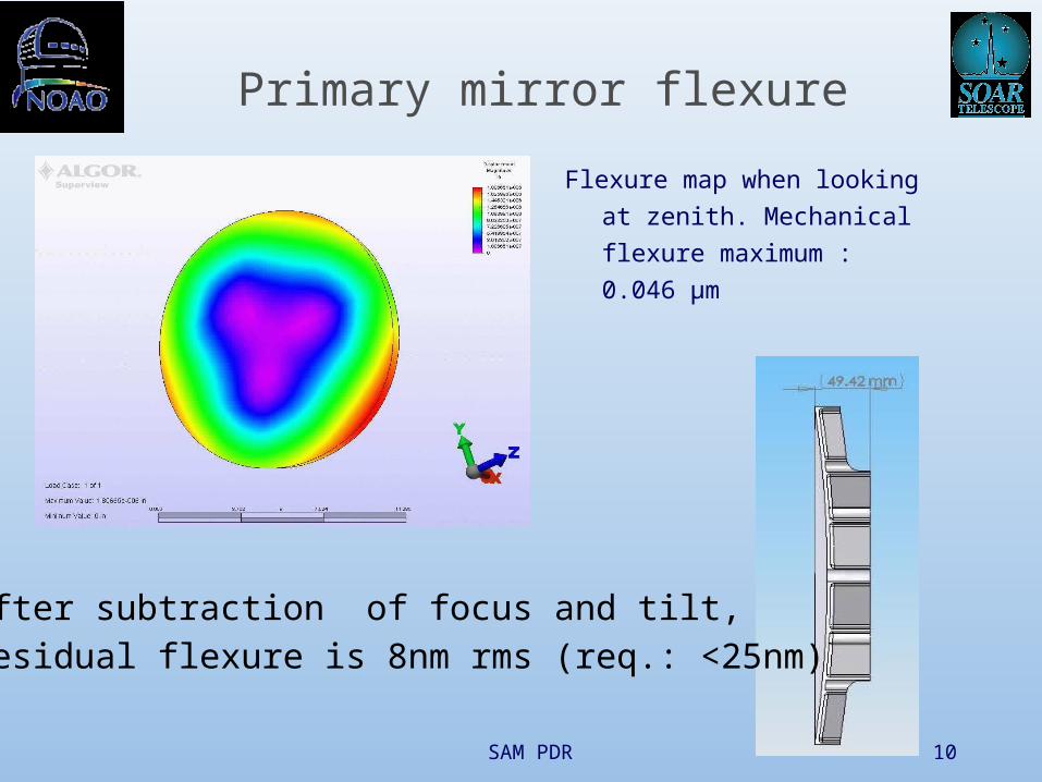
Primary mirror flexure
Flexure map when looking at
zenith. Mechanical flexure
maximum : 0.046 µm
After subtraction of focus and tilt,residual flexure is 8nm rms (req.: <25nm)

SAM PDR 11
Pointing assembly (1)
M1
Range ± 500 µmFlexure post
Lower plate
upper plate
M1
LLT points by pivoting M1around the focus (or curvature center) of M2 using 3 flexure posts

SAM PDR 12
Pointing assembly (2)
Material: Aluminum 6061 T6
Mass: 2.100 kg
Motor M-230.10 Motor M-230.10
Flexure post
Lower plate
M1
SAM PDR 13
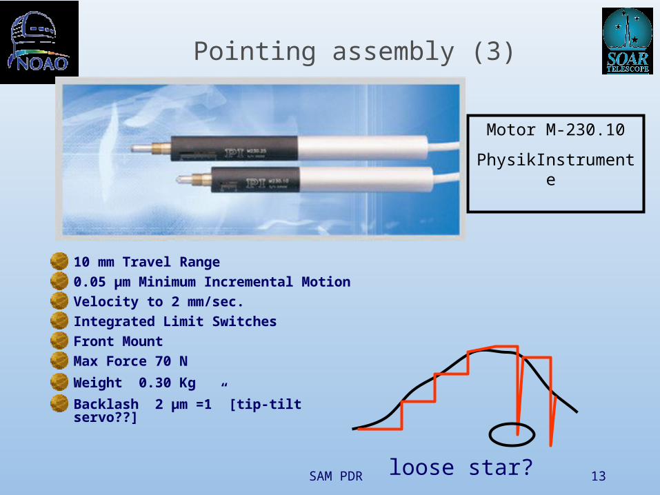
10 mm Travel Range
0.05 µm Minimum Incremental Motion
Velocity to 2 mm/sec.
Integrated Limit Switches
Front Mount
Max Force 70 N
Weight 0.30 Kg
Backlash 2 µm =1” [tip-tilt servo??]
Motor M-230.10
PhysikInstrumente
Pointing assembly (3)
loose star?
SAM PDR 14
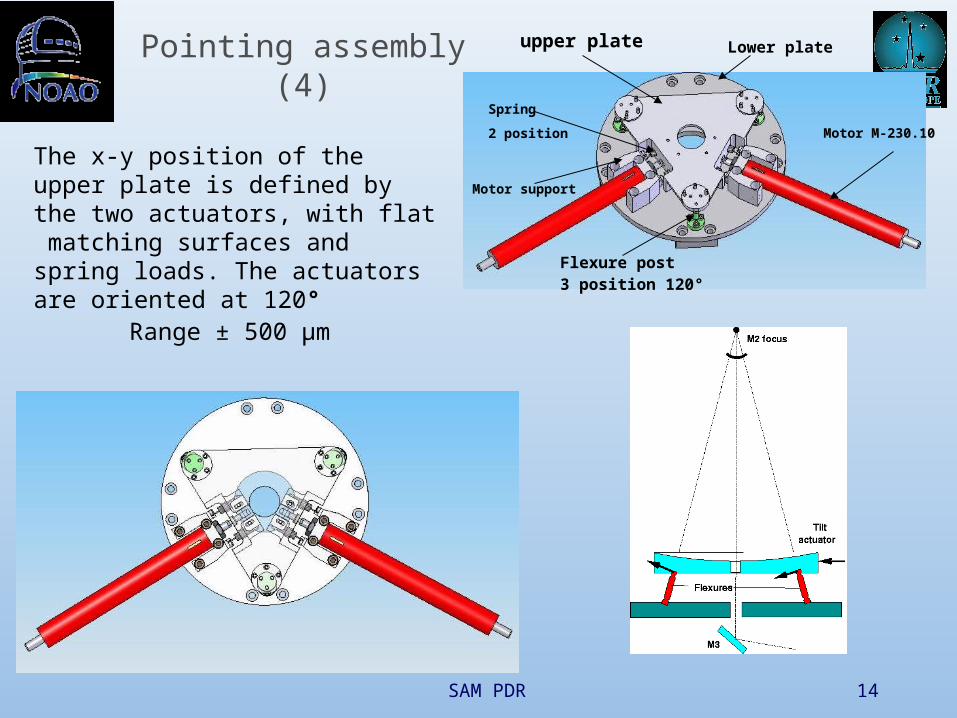
The x-y position of the upper plate is defined by the two actuators, with flat matching surfaces and spring loads. The actuators are oriented at 120°
Range ± 500 µm
upper plate Lower plate
Motor M-230.10
Motor support
Spring
2 position
Flexure post3 position 120°
Pointing assembly (4)
SAM PDR 15
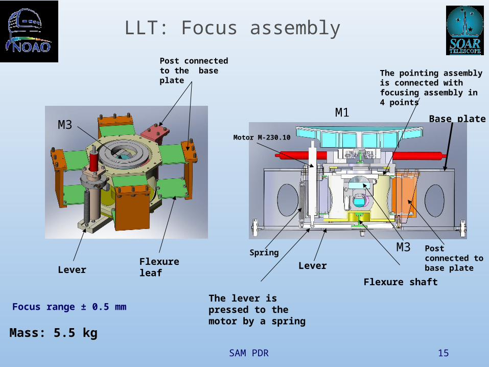
The pointing assembly is connected with focusing assembly in 4 points
Lever
Spring
The lever is pressed to the motor by a spring
LeverFlexure leaf
Base plateM1
Flexure shaft
Motor M-230.10
M3 Post connected to base plate
Post connected to the base plate
M3
LLT: Focus assembly
Focus range ± 0.5 mm
Mass: 5.5 kg
SAM PDR 16
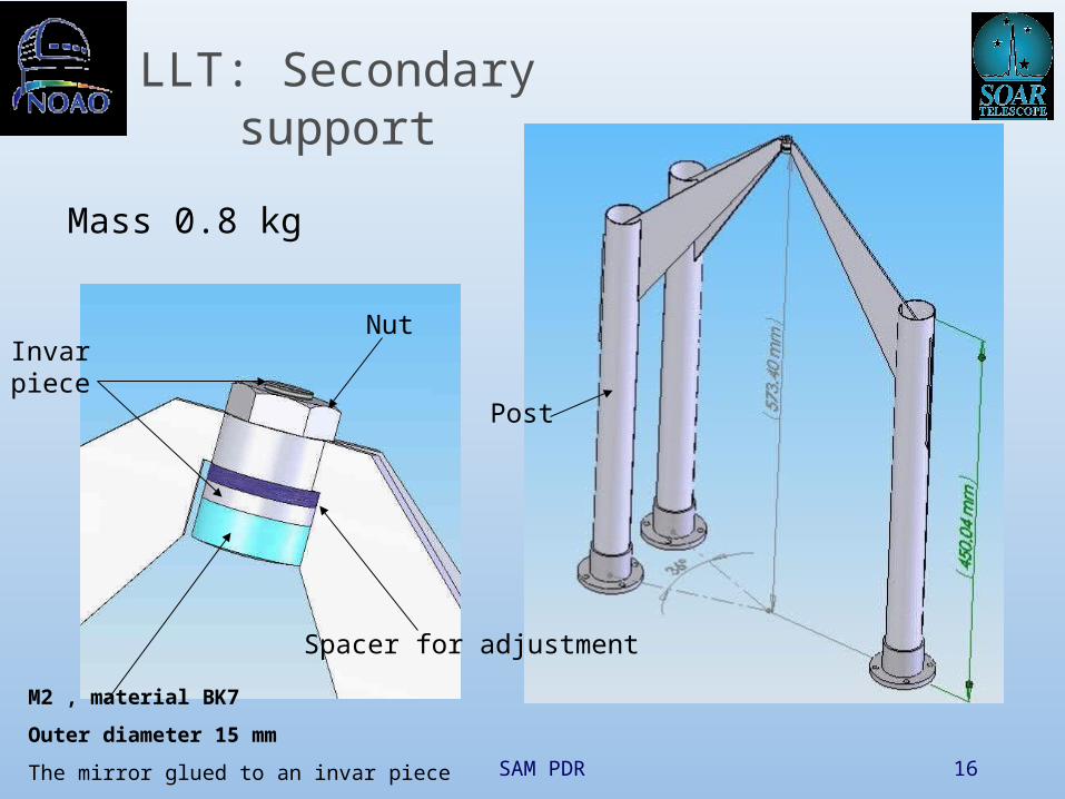
LLT: Secondary support
Invar piece
M2 , material BK7
Outer diameter 15 mm
The mirror glued to an invar piece
Spacer for adjustment
Nut
Post
Mass 0.8 kg
SAM PDR 17
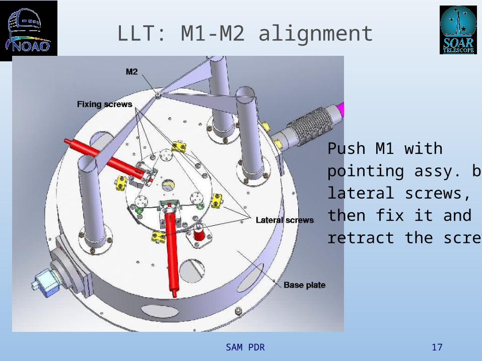
LLT: M1-M2 alignment
Push M1 withpointing assy. bylateral screws,then fix it andretract the screws

SAM PDR 18
LLT: M3 support and ATP
M3 tilts aligned manually (accessible from outside LLT)
AM3 sends star light to lens+CCD (boresight camera, ATP)
ATP is used as auto-collimator for alignment
SAM PDR 19
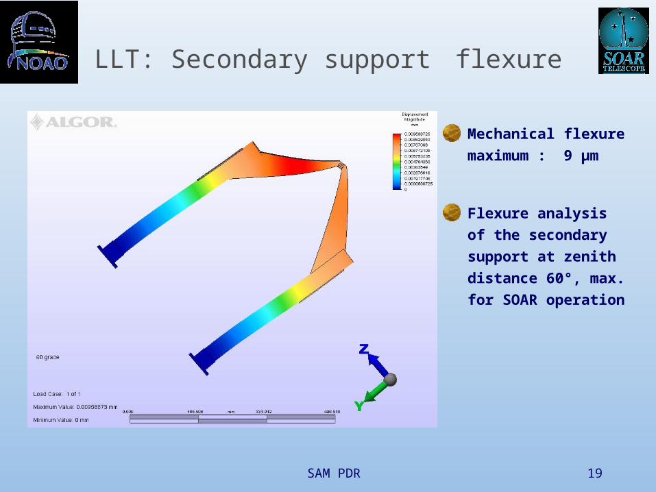
LLT: Secondary support flexure
Mechanical flexure
maximum : 9 µm
Flexure analysis of the
secondary support at
zenith distance 60°,
max. for SOAR
operation

SAM PDR 20
Flexure analysis of the LLT structure at zenith distance 60°
Mount at 3 fixed points
Mechanical flexure of M2:
18 µm lateral, 27 µm axial
Relative displacement between M1
axis and M2 focus: 1.1 µm lateral
(need <73 µm )
Overall LLT tilt: 4.7”
SAM PDR 21
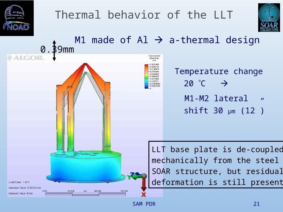
Thermal behavior of the LLT
Temperature change
20 C
M1-M2 lateral shift
30 µm (12”)
LLT base plate is de-coupled mechanically from the steel SOAR structure, but residualdeformation is still present
0.39mmM1 made of Al a-thermal design

SAM PDR 22
LLT: Protective cylinder and shutter
Iris shutter
Mass: 5.0 kg
LLT can be additionally protected by a plastic cap installed manually
Shutter motor

SAM PDR 23
LLT interface with the SOAR telescope
3 steel posts,reproducible mount

SAM PDR 24
Laser Launch Telescope mounted
Mounted above the SOAR secondary
M4
Total LLT mass: 18.7kg
SAM PDR 25
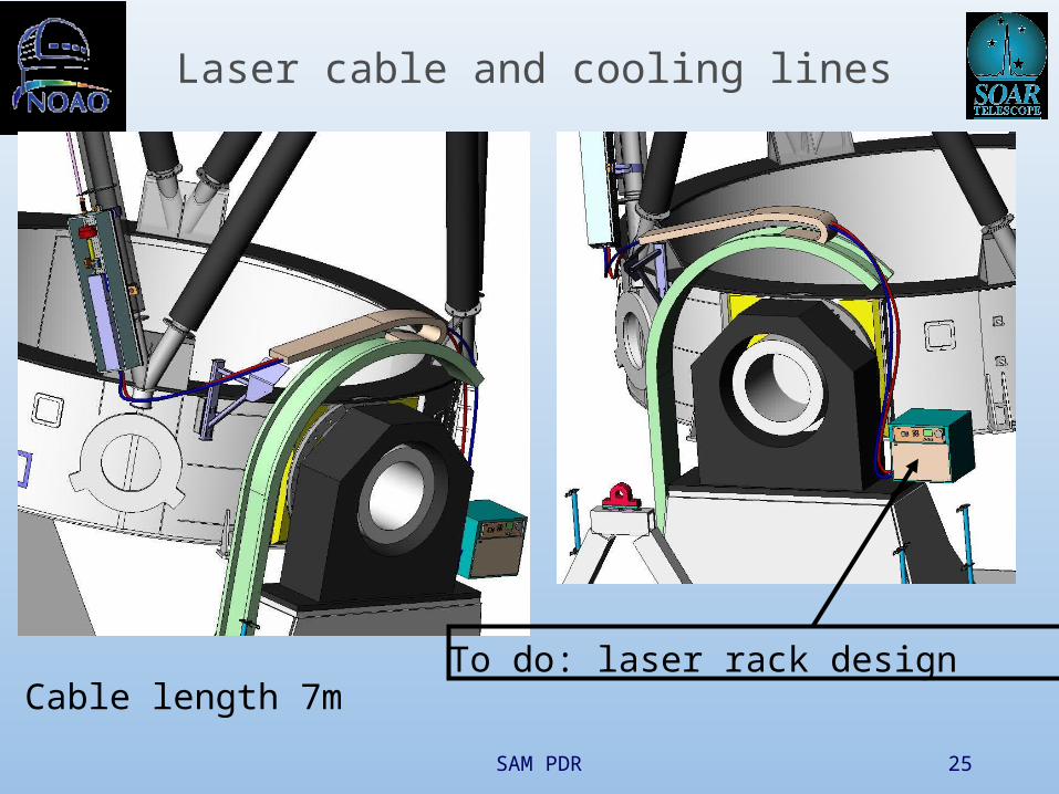
Laser cable and cooling lines
Cable length 7mTo do: laser rack design
SAM PDR 26
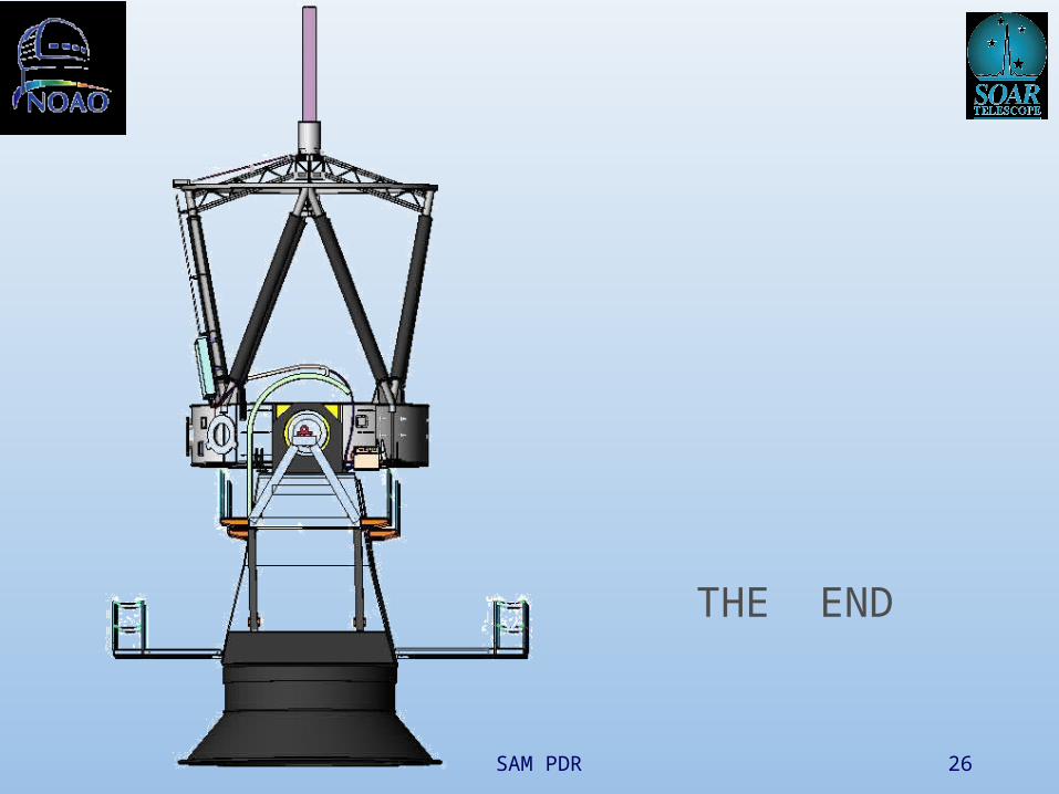
THE END