[email protected] Raritansupport.raritan.com/px2/version-3.0.0/PX2_MIB_Guide.pdf1 +1.732.764.8886...
34
1 +1.732.764.8886 +1.732.764.8887 [email protected] Raritan.com 1 Introduction ................................................................................................................. 4 2 Intended Audience ...................................................................................................... 5 3 Using the Correct Version of the MIB ........................................................................ 5 4 Use of a MIB Browser ................................................................................................ 5 5 Structure of the PX2-MIB ........................................................................................... 6 ............................................................................................................................................. 7 5.1 Traps.................................................................................................................... 7 5.2 Configuration ...................................................................................................... 8 5.2.1 Unit.................................................................................................................. 8 5.2.2 Inlets ................................................................................................................ 8 5.2.3 overCurrentProtector ....................................................................................... 9 5.2.4 Outlets ............................................................................................................. 9 5.2.5 externalSensors ............................................................................................... 9 5.2.6 serverReachability ......................................................................................... 10 5.2.7 transferSwitch ............................................................................................... 10 5.3 Control .............................................................................................................. 10 5.4 Measurements ................................................................................................... 11 5.4.1 Log ................................................................................................................ 11 5.4.2 Reliability ...................................................................................................... 12 6 MIB Basics ................................................................................................................ 12 6.1 SNMP Objects................................................................................................... 12 6.1.1 Scalar Object ................................................................................................. 12 6.1.1.1 Example................................................................................................. 12 6.1.2 Columnar Object ........................................................................................... 13 6.1.2.1 Example................................................................................................. 13 6.2 Textual Conventions ......................................................................................... 13 6.2.1 SensorTypeEnumeration ............................................................................... 13 6.2.1.1 Example................................................................................................. 14 6.2.2 SensorStateEnumeration ............................................................................... 14 6.2.2.1 Example................................................................................................. 14 6.2.3 SensorUnitsEnumeration............................................................................... 15 6.2.3.1 Example................................................................................................. 15 7 Use Cases .................................................................................................................. 16 7.1 Symbolic OID and Numeric OID ..................................................................... 16 7.1.1 Example......................................................................................................... 16 7.2 Determining whether to use Signed or Unsigned values .................................. 16 7.2.1 Signed Values ............................................................................................... 16 7.2.2 Unsigned Values ........................................................................................... 16 7.2.3 Method for Determining whether to use Signed or Unsigned values ........... 17 7.2.4 Example where Unsigned values must be Used ........................................... 17 7.2.4.1 Step 1: Retrieve the value ..................................................................... 17 7.2.4.1.1 Determine the OID .......................................................................... 17 7.2.4.1.1.1 Get the value using SNMP v2c ................................................ 18
Transcript of [email protected] Raritansupport.raritan.com/px2/version-3.0.0/PX2_MIB_Guide.pdf1 +1.732.764.8886...

1
+1.732.764.8886
+1.732.764.8887
Raritan.com
1 Introduction ................................................................................................................. 4
2 Intended Audience ...................................................................................................... 5 3 Using the Correct Version of the MIB ........................................................................ 5 4 Use of a MIB Browser ................................................................................................ 5 5 Structure of the PX2-MIB ........................................................................................... 6 ............................................................................................................................................. 7
5.1 Traps .................................................................................................................... 7 5.2 Configuration ...................................................................................................... 8
5.2.1 Unit .................................................................................................................. 8 5.2.2 Inlets ................................................................................................................ 8
5.2.3 overCurrentProtector ....................................................................................... 9 5.2.4 Outlets ............................................................................................................. 9
5.2.5 externalSensors ............................................................................................... 9 5.2.6 serverReachability ......................................................................................... 10
5.2.7 transferSwitch ............................................................................................... 10 5.3 Control .............................................................................................................. 10 5.4 Measurements ................................................................................................... 11
5.4.1 Log ................................................................................................................ 11 5.4.2 Reliability ...................................................................................................... 12
6 MIB Basics ................................................................................................................ 12 6.1 SNMP Objects ................................................................................................... 12
6.1.1 Scalar Object ................................................................................................. 12
6.1.1.1 Example................................................................................................. 12
6.1.2 Columnar Object ........................................................................................... 13 6.1.2.1 Example................................................................................................. 13
6.2 Textual Conventions ......................................................................................... 13
6.2.1 SensorTypeEnumeration ............................................................................... 13 6.2.1.1 Example................................................................................................. 14
6.2.2 SensorStateEnumeration ............................................................................... 14 6.2.2.1 Example................................................................................................. 14
6.2.3 SensorUnitsEnumeration............................................................................... 15 6.2.3.1 Example................................................................................................. 15
7 Use Cases .................................................................................................................. 16 7.1 Symbolic OID and Numeric OID ..................................................................... 16
7.1.1 Example......................................................................................................... 16
7.2 Determining whether to use Signed or Unsigned values .................................. 16 7.2.1 Signed Values ............................................................................................... 16
7.2.2 Unsigned Values ........................................................................................... 16 7.2.3 Method for Determining whether to use Signed or Unsigned values ........... 17 7.2.4 Example where Unsigned values must be Used ........................................... 17
7.2.4.1 Step 1: Retrieve the value ..................................................................... 17 7.2.4.1.1 Determine the OID .......................................................................... 17
7.2.4.1.1.1 Get the value using SNMP v2c ................................................ 18
2
+1.732.764.8886
+1.732.764.8887
Raritan.com
7.2.4.1.1.2 Get the value using SNMP v3 .................................................. 18
7.2.4.2 Step 2: Use the retrieved value to determine whether to use signed or unsigned values.
18 7.2.5 Example where Signed values must be Used ................................................ 19
7.2.5.1 Step 1: Retrieve the value ..................................................................... 19 7.2.5.1.1 Determine the OID .......................................................................... 19
7.2.5.1.1.1 Get the value using SNMP v2c ................................................ 20 7.2.5.1.1.2 Get the value using SNMP v3 .................................................. 20
7.2.5.2 Step 2: Use the retrieved value to determine whether to use signed or unsigned values.
20
7.3 Retrieving and Interpreting the most recent value of a Sensor ......................... 21 7.3.1 Example......................................................................................................... 21
7.3.1.1 Step 1: Retrieve the value ..................................................................... 21 7.3.1.1.1 Determine the OID .......................................................................... 21
7.3.1.1.1.1 Get the value using SNMP v2c ................................................ 22 7.3.1.1.1.2 Get the value using SNMP v3 .................................................. 22
7.3.1.2 Step 2: Retrieve the decimalDigits for this sensor ................................ 22
7.3.1.2.1 Determine the OID .......................................................................... 22 7.3.1.2.1.1 Get the value using SNMP v2c ................................................ 23
7.3.1.2.1.2 Get the value using SNMP v3 .................................................. 23 7.3.1.3 Step 3: Retrieve the units for this sensor ............................................... 23
7.3.1.3.1 Determine the OID .......................................................................... 24
7.3.1.3.1.1 Get the value using SNMP v2c ................................................ 24
7.3.1.3.1.2 Get the value using SNMP v3 .................................................. 24 7.3.1.4 Step 4: Scale the value .......................................................................... 25
7.4 Determining the types of supported outlet sensors ........................................... 25
7.4.1 Example......................................................................................................... 25 7.4.1.1 Determining the OID............................................................................. 25
7.4.1.2 Retrieving the Value ............................................................................. 25 7.4.1.2.1 Get the value using SNMP v2c ....................................................... 26
7.4.1.2.2 Get the value using SNMP v3 ......................................................... 26 7.4.1.3 Interpreting the Value ........................................................................... 26
7.4.1.3.1.1 Interpreting the Data without a MIB Browser. ......................... 26 7.4.1.3.1.2 Interpreting the Data with a MIB Browser. .............................. 27
7.5 Switch an Outlet Off ......................................................................................... 27
7.5.1 Example......................................................................................................... 27 7.5.1.1 Determining the OID............................................................................. 27
7.5.1.2 Setting the Value ................................................................................... 28 7.5.1.2.1 Set the value using SNMP v2c ........................................................ 28 7.5.1.2.2 Set the value using SNMP v3 .......................................................... 28
7.6 Retrieve and Interpreting an External Sensor Reading ..................................... 28 7.6.1 Example......................................................................................................... 29
7.6.1.1 Step 1: Retrieve the value ..................................................................... 29

3
+1.732.764.8886
+1.732.764.8887
Raritan.com
7.6.1.1.1 Determine the OID .......................................................................... 29
7.6.1.1.1.1 Get the value using SNMP v2c ................................................ 29 7.6.1.1.1.2 Get the value using SNMP v3 .................................................. 29
7.6.1.2 Step 2: Retrieve the decimalDigits for this sensor ................................ 30 7.6.1.2.1 Determine the OID .......................................................................... 30
7.6.1.2.1.1 Get the value using SNMP v2c ................................................ 30
7.6.1.2.1.2 Get the value using SNMP v3 .................................................. 30 7.6.1.3 Step 3: Retrieve the units for this sensor ............................................... 30
7.6.1.3.1 Determine the OID .......................................................................... 30 7.6.1.3.1.1 Get the value using SNMP v2c ................................................ 31
7.6.1.3.1.2 Get the value using SNMP v3 .................................................. 31 7.6.1.4 Step 4: Scale the value .......................................................................... 31
7.7 Set PDU Name .................................................................................................. 31 7.7.1 Example......................................................................................................... 32
7.7.1.1 Determining the OID............................................................................. 32 7.7.1.2 Setting the Value ................................................................................... 32
7.7.1.2.1 Set the value using SNMP v2c ........................................................ 32
7.7.1.2.2 Set the value using SNMP v3 .......................................................... 32 7.8 Notification (Trap/Inform) Received when the Outlet Current exceeds the Upper Critical
Threshold ...................................................................................................................... 32 7.8.1 Example......................................................................................................... 33

4
+1.732.764.8886
+1.732.764.8887
Raritan.com
PX2 Enterprise MIB User Guide
Introduction

5
+1.732.764.8886
+1.732.764.8887
Raritan.com
This document describes Raritan’s PX-G2 SNMP MIB. At a high level, the MIB is structured as a tree
with several branches, each representing an important functional area. After discussing several important
SNMP constructs, the contents of each branch will be described. Several common customer use cases are
also described.
Intended Audience The audiences of this document are users who work with the PX2 MIB. In general, there are two types of
users.
Management Programs
Humans using MIB browsers.
The concerns of both sets of users are addressed here.
Using the Correct Version of the MIB
Since the functionality of the MIB may change with the firmware version, it is necessary to obtain the
appropriate version of the MIB version from the device.
Use of a MIB Browser A MIB browser is a helpful tool for understanding the structure and operation of the MIB. Raritan does
not recommend any particular MIB browser and users may use any MIB browser of their choosing. For
concreteness, this document uses the iReasoning MIB Browser whenever MIB browsers are referenced.
Users should load the PX2-MIB into the MIB Browser and refer to it as they read the document.
A sample of the screen from the iReasoning MIB Browser is shown below.

6
+1.732.764.8886
+1.732.764.8887
Raritan.com
Structure of the PX2-MIB
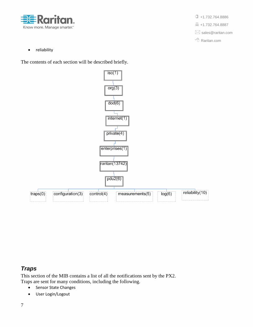
As shown below, Raritan’s PX2 MIB is organized as a tree with the following branches.
traps
configuration
measurements
log
7
+1.732.764.8886
+1.732.764.8887
Raritan.com
reliability
The contents of each section will be described briefly.
Traps
This section of the MIB contains a list of all the notifications sent by the PX2.
Traps are sent for many conditions, including the following.
Sensor State Changes
User Login/Logout

8
+1.732.764.8886
+1.732.764.8887
Raritan.com
User Configuration Changes
Device Firmware Updates.
The notifications contain objects that are transmitted with the notification. These objects, known as
varbinds, contain additional information about the reported event, and are listed in the OBJECTS clause
of the notification. The order in which the varbinds appear in the list is important.
Configuration
This section of the MIB is used for configuration. There are separate subsections for the different
components of the PDU as described below.
Unit
Unit configuration contains the following tables.
NameplateTable: Includes information such as the name of manufacturer, the model type, and serial
number.
UnitConfigurationTable: Includes information such as network settings, the name of the unit, the
number of inlets, outlets, and over current protectors. ControllerConfigurationTable: Includes
information such as the hardware and software versions of the different boards in the system.
LogConfigurationTable: Includes information on the Log . The log contains historical measurement
data then set corresponding OID’s defined under this table.
UnitSensorConfigurationTable: Includes information such as thresholds for all unit level sensors
Inlets
An inlet can be single phase or three phase depending on the number of poles. For instance, 3-phase inlets
have 3 poles representing the different lines (phases) such as L1, L2, L3 for currents and L1-L2, L2-L3,
L3-L1 for voltages.
Inlet configuration contains the following tables.
InletConfigurationTable: Includes, for each inlet, information such as the inlet current rating, voltage
rating, frequency rating, the number of poles, and the types of inlet sensors and inlet pole sensors.
InletSensorConfigurationTable: Includes information such as thresholds for all inlet sensors.
InletPoleSensorConfigurationTable: Includes information such as thresholds for all inlet pole sensors.

9
+1.732.764.8886
+1.732.764.8887
Raritan.com
overCurrentProtector
Overcurrent protectors are the circuit breakers and fuses in the system.
Overcurrent Protector configuration contains the following tables.
OvercurrentProtectorConfigurationTable: Includes, for each overcurrent protector, information such
as the current rating, the type, poles, and the types of overcurrent protector sensors.
OvercurrentProtectorSensorConfigurationTable: Includes information such as thresholds for all
overcurrent protector sensors.
Outlets
An outlet can be single phase or three phase depending on the number of poles. For instance, 3-phase
outlets have 3 poles representing the different lines (phases) such as L1, L2, L3 for currents and L1-L2,
L2-L3, L3-L1 for voltages.
Outlet configuration contains the following tables.
OutletConfigurationTable: Includes, for each outlet, information such as the inlet current rating, voltage
rating, the number of poles, and the types of outlet sensors and outlet pole sensors.
OutletSensorConfigurationTable: Includes information such as thresholds for all outlet sensors.
OutletPoleSensorConfigurationTable: Includes information such as thresholds for all outlet pole
sensors.
externalSensors
External sensors are attached to the PDU and include humidity, temperature, and contact sensors.
External Sensor configuration contains the following tables.
ExternalSensorConfigurationTable: Includes, for each external sensor, information such as the serial
number, name, the X, Y, Z labels and the thresholds.
ExternalSensorTypeDefaultThresholdsTable: Includes the default thresholds for each type of numeric
external sensor.
10
+1.732.764.8886
+1.732.764.8887
Raritan.com
PeripheralDevicePackageTable: Includes, for each G2 sensor package such as DXT2H2, information
such as the firmware version and when the firmware was last updated.
serverReachability
ServerReachabilityTable: Includes a list of servers and whether the server reachability feature is enabled
for it.
transferSwitch
Transfer Switch configuration contains the following tables.
TransferSwitchConfigurationTable: Includes, for each transfer switch, information such as the name,
the preferred inlet, whether automatic transfer is enabled, and the types of transfer switch sensors.
TransferSwitchSensorConfigurationTable: Includes information such as thresholds for all transfer
switch sensors.
Control
This section is used to control the behavior of several of the components
OutletSwitchControlTable: Allows outlets to be switched on or off.
TransferSwitchControlTable: Allows Manual Transfers to be executed.
ActuatorTable: Allows the state of a n actuator such as dry contact to be changed.
RCMControlTable: Allows Self-Test of an RCM to be executed.
InletSensorControlTable: Allows sensors such as active energy for an inlet to be reset.
OutletSensorControlTable: Allows sensors such as active energy for an outlet to be reset.

11
+1.732.764.8886
+1.732.764.8887
Raritan.com
Measurements
This section is used to obtain the current values of the sensors.
UnitSensorMeasurementsTable: Includes information such as the value and state for each unit sensor.
InletSensorMeasurementsTable: Includes information such as the value and state for each inlet sensor.
InletPoleSensorMeasurementsTable: Includes information such as the value and state for each inlet
pole sensor.
OvercurrentprotectorSensorMeasurementsTable: Includes information such as the value and state for
each overcurrent protector sensor.
OutletSensorMeasurementsTable: Includes information such as the value and state for each outlet
sensor.
OutletPoleSensorMeasurementsTable: Includes information such as the value and state for each outlet
pole sensor.
ExternalSensorMeasurementsTable: Includes information such as the value and state for each external
sensor.
TransferSwitchMeasurementsTable: Includes information such as the value and state for each transfer
switch sensor.
Log
The log contains historical data on the sensors in the system. The log is a circular buffer with pointers to
the oldest entry and most recent entry.
LogIndexTable: Includes the pointer to the oldest entry (oldestLogID) and the pointer to the newest entry
(newestLogID).
LogTimestampTable: Includes a timestamp indicating when the entry was written to the log.
UnitSensorLogTable: Includes information such as the value and state for each unit sensor.
InletSensorLogTable: Includes information such as the value and state for each inlet sensor.
InletPoleSensorLogTable: Includes information such as the value and state for each inlet pole sensor.
OvercurrentprotectorSensorLogTable: Includes information such as the value and state for each
overcurrent protector sensor.
OutletSensorLogTable: Includes information such as the value and state for each outlet sensor.
OutletPoleSensorLogTable: Includes information such as the value and state for each outlet pole sensor.
ExternalSensorLogTable: Includes information such as the value and state for each external sensor.

12
+1.732.764.8886
+1.732.764.8887
Raritan.com
TransferSwitchLogTable: Includes information such as the value and state for each transfer switch
sensor.
Reliability
This section contains data on the reliability of components of the PDU.
ReliabilityDataTable: Includes information such as the trip counts for circuit breakers and the number of
checksum errors during communication between control boards and slave boards.
ReliabilityLogErrorTable: Includes the entries from the ReliabilityDataTable that are in an error
condition because their values have dropped below the corresponding reliability data threshold.
MIB Basics
Management of a system requires retrieving and changing management information and receiving events
from the managed system. Management information and the events are specified in documents called
Management Information Base (MIB) documents. This section describes several important MIB
constructs.
SNMP Objects
Management information in the MIB is organized as SNMP objects. Objects are uniquely identified with
Object Identifiers.
Objects can be either scalar or columnar.
Scalar Object
A scalar object has only one instance and that instance is identified by adding a suffix of zero (0) to the
OID.
Example
An example of a scalar object in the MIB is pduCount which has the OID 1.3.6.1.4.1.13742.6.3.1. The
single instance of pduCount is identified by adding a 0 suffix to the OID as in 1.3.6.1.4.1.13742.6.3.1.0

13
+1.732.764.8886
+1.732.764.8887
Raritan.com
Columnar Object
A columnar object has zero, one, or more instances. Columnar objects are organized into tables. Each
table has an INDEX clause that specifies the indexing scheme for the table. An instance of a columnar
object is identified by adding to the OID a suffix determined by the indexing scheme of the table.
Example
An example of a columnar object in the MIB is outletName which is an object in the
outletConfigurationTable table. The INDEX clause of this table is INDEX { pduId, outletId }.
The instance of the object is identified as shown below.
Object: outletName
Table Index Clause: INDEX { pduId, outletId, }
OID: 1.3.6.1.4.1.13742.6.3.5.3.1.3
Suffix: pduId.outletId.
Instance: OID.suffix or 1.3.6.1.4.1.13742.6.3.5.3.1.3. pduId.outletId
Suppose the user wishes to retrieve the outlet name for outlet 12.
Then the following values must be used.
pduId = 1 for all existing applications.
outletId = 12
So the suffix for this instance is 1.12 and finally the instance is
1.3.6.1.4.1.13742.6.3.5.3.1.3.1.12
Textual Conventions
Several objects in the MIB are encoded using TEXTUAL-CONVENTIONS. The SYNTAX clause of the
object specifies the TEXTUAL-CONVENTION.
Several important TEXTUAL-CONVENTIONs are described below.
SensorTypeEnumeration
This Textual-Convention is used to determine the type of sensor.

14
+1.732.764.8886
+1.732.764.8887
Raritan.com
Example
The externalSensorType object in the externalSensorConfigurationTable has SYNTAX of
SensorTypeEnumeration. When this object is retrieved, its value must be interpreted using
SensorTypeEnumeration. Suppose the retrieved value is 11. An inspection of SensorTypeEnumeration,
shown below, indicates that the value 11 maps to Humidity. The sensor is, therefore, a humidity sensor.
SensorTypeEnumeration ::= TEXTUAL-CONVENTION
STATUS current
DESCRIPTION
"The types a sensor can be."
SYNTAX INTEGER {
rmsCurrent(1),
peakCurrent(2),
unbalancedCurrent(3),
rmsVoltage(4),
activePower(5),
apparentPower(6),
powerFactor(7),
activeEnergy(8),
apparentEnergy(9),
temperature(10),
humidity(11),
airFlow(12),
airPressure(13),
onOff(14),
trip(15),
SensorStateEnumeration
This Textual-Convention is used to determine the state of the sensor.
Example
The measurementsExternalSensorState object in the externalSensorMeasurementsTable has SYNTAX of
SensorStateEnumeration. When this object is retrieved, its value must be interpreted using
SensorStateEnumeration. Suppose the retrieved value is 6. An inspection of SensorStateEnumeration,
shown below, indicates that the value 6 maps to aboveUpperCritical. The sensor state is, therefore, above
upper critical.

15
+1.732.764.8886
+1.732.764.8887
Raritan.com
SensorStateEnumeration ::= TEXTUAL-CONVENTION
STATUS current
DESCRIPTION
"The states a sensor can be in."
SYNTAX INTEGER { unavailable(-1),
open(0),
closed(1),
belowLowerCritical(2),
belowLowerWarning(3),
normal(4),
aboveUpperWarning(5),
aboveUpperCritical(6),
on(7),
off(8),
SensorUnitsEnumeration
This Textual-Convention is used to determine the units corresponding to the sensor reading.
Example
Suppose the reading for the outlet activePower sensor has been retrieved. In order to determine the units
of the sensor reading, the outletSensorUnits object in the outletSensorConfigurationTable must be
retrieved.
This object has a SYNTAX of SensorUnitsEnumeration. The retrieved value is 3 and an inspection of
SensorUnitsEnumeration indicates that the value 3 maps to watt. The sensor units are, therefore, watts.
SensorUnitsEnumeration ::= TEXTUAL-CONVENTION
STATUS current
DESCRIPTION
"The sensor units."
SYNTAX INTEGER { none(-1),
other(0),
volt(1),
amp(2),
watt(3),
voltamp(4),
wattHour(5),
voltampHour(6),
degreeC(7),

16
+1.732.764.8886
+1.732.764.8887
Raritan.com
Use Cases This section of the document describes several common use cases. Examples are shown with Net-SNMP
command line tools such as snmpget and snmpset.
Symbolic OID and Numeric OID
An OID is usually specified in the numeric form such as 1.3.6.1.4.1.13742.6.3.5.3.1.3. MIB browsers
allow the OID to be specified in a symbolic form if the MIB has been imported into the browser.
Example
For the outletName which is an object in the outletConfigurationTable, the OID is as shown
below.
Numeric Form: 1.3.6.1.4.1.13742.6.3.5.3.1.3
Symbolic Form: PDU2-MIB::outletName
For the outletName of outlet 12, the OID is as shown below.
Numeric Form: 1.3.6.1.4.1.13742.6.3.5.3.1.3.1.12
Symbolic Form: PDU2-MIB::outletName.1.12
All examples will use the Symbolic Form of the OID.
.
Determining whether to use Signed or Unsigned values
The SensorConfigurationTables, SensorLogTables, and SensorMeasurementsTables contain both signed
and unsigned representations of the thresholds, maximum values, minimum values, measured values,
data log average, data log maximum and data log minimum values.
Signed Values
Signed values are used for quantities, such as Phase Angle and Temperature, which can assume both
negative and positive values. The Syntax clause for signed quantities is shown below. SYNTAX Integer32
Unsigned Values
They are used for quantities, such as Voltage and Active Energy, which cannot assume negative values.
The Syntax clause for unsigned quantities is shown below.

17
+1.732.764.8886
+1.732.764.8887
Raritan.com
SYNTAX Unsigned32
Method for Determining whether to use Signed or Unsigned values
For each sensor, the SensorSignedMinimum object in the SensorConfigurationTable
indicates whether signed or unsigned objects must be used.
If the value of SensorSignedMinimum is less than 0, then signed values must be used.
If the value of SensorSignedMinimum is greater than or equal to 0, then unsigned values must be
used.
Example where Unsigned values must be Used
Suppose the user wishes to determine whether to use signed or unsigned values for the RMS voltage
sensor for outlet 12.
Step 1: Retrieve the value
The required object is outletSensorSignedMinimum in the outletSensorConfigurationTable.
Determine the OID
The instance of the object is identified as shown below.
Object: outletSensorSignedMinimum
Table Index Clause: INDEX { pduId, outletId, sensorType }
OID: 1.3.6.1.4.1.13742.6.3.5.4.1.27
Symbolic OID: PDU2-MIB::outletSensorSignedMinimum
Suffix: pduId.outletId.sensorType
Instance: OID.suffix or
PDU2-MIB:: outletSensorSignedMinimum.pduId.outletId.sensorType
pduId = 1 for all existing applications.
outletId = 12
sensorType determined from SensorTypeEnumeration as 4 for rmsVoltage.
So the suffix for this instance is 1.12.4 and finally the instance is PDU2-MIB::outletSensorSignedMinimum.1.12.4
18
+1.732.764.8886
+1.732.764.8887
Raritan.com
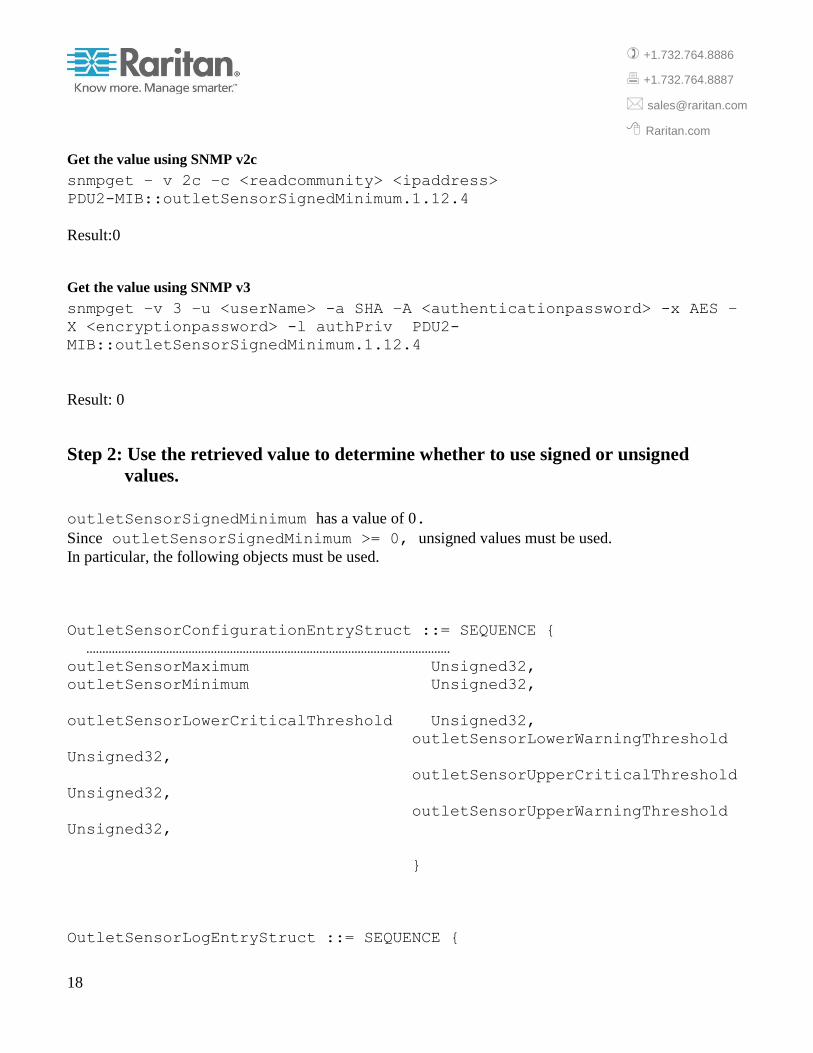
Get the value using SNMP v2c
snmpget – v 2c –c <readcommunity> <ipaddress>
PDU2-MIB::outletSensorSignedMinimum.1.12.4
Result:0
Get the value using SNMP v3
snmpget –v 3 –u <userName> -a SHA –A <authenticationpassword> -x AES –
X <encryptionpassword> -l authPriv PDU2-
MIB::outletSensorSignedMinimum.1.12.4
Result: 0
Step 2: Use the retrieved value to determine whether to use signed or unsigned
values.
outletSensorSignedMinimum has a value of 0.
Since outletSensorSignedMinimum >= 0, unsigned values must be used.
In particular, the following objects must be used.
OutletSensorConfigurationEntryStruct ::= SEQUENCE {
……………………………………………………………………………………………………
outletSensorMaximum Unsigned32,
outletSensorMinimum Unsigned32,
outletSensorLowerCriticalThreshold Unsigned32,
outletSensorLowerWarningThreshold
Unsigned32,
outletSensorUpperCriticalThreshold
Unsigned32,
outletSensorUpperWarningThreshold
Unsigned32,
}
OutletSensorLogEntryStruct ::= SEQUENCE {

19
+1.732.764.8886
+1.732.764.8887
Raritan.com
logOutletSensorAvgValue Unsigned32,
logOutletSensorMaxValue Unsigned32,
logOutletSensorMinValue Unsigned32,
}
OutletSensorMeasurementsEntryStruct ::= SEQUENCE {
measurementsOutletSensorValue
Unsigned32,
}
Example where Signed values must be Used
Suppose the user wishes to determine whether to use signed or unsigned values for the Phase Angle
sensor for outlet 12.
Step 1: Retrieve the value
The required object is outletSensorSignedMinimum in the outletSensorConfigurationTable.
Determine the OID
The instance of the object is identified as shown below.
Object: outletSensorSignedMinimum
Table Index Clause: INDEX { pduId, outletId, sensorType }
OID: 1.3.6.1.4.1.13742.6.3.5.4.1.27
Symbolic OID: PDU2-MIB:: outletSensorSignedMinimum
Suffix: pduId.outletId.sensorType
Instance: OID.suffix or
PDU2-MIB:: outletSensorSignedMinimum.pduId.outletId.sensorType
pduId = 1 for all existing applications.
outletId = 12
sensorType determined from SensorTypeEnumeration as 24 for phaseAngle.

20
+1.732.764.8886
+1.732.764.8887
Raritan.com
So the suffix for this instance is 1.12.24 and finally the instance is PDU2-MIB::outletSensorSignedMinimum.1.12.24
Get the value using SNMP v2c
snmpget – v 2c –c <readcommunity> <ipaddress>
PDU2-MIB::outletSensorSignedMinimum.1.12.24
Result: -180
Get the value using SNMP v3
snmpget –v 3 –u <userName> -a SHA –A <authenticationpassword> -x AES –
X <encryptionpassword> -l authPriv PDU2-
MIB::outletSensorSignedMinimum.1.12.24
Result: -180
Step 2: Use the retrieved value to determine whether to use signed or unsigned
values.
outletSensorSignedMinimum has a value of -180.
Since outletSensorSignedMinimum < 0, signed values must be used.
In particular, the following objects must be used.
OutletSensorConfigurationEntryStruct ::= SEQUENCE {
……………………………………………………………………………………………………
outletSensorSignedMaximum Integer32,
outletSensorSignedMinimum Integer 32,
outletSensorSignedLowerCriticalThreshold Integer 32,
outletSensorSignedLowerWarningThreshold Integer 32,
outletSensorSignedUpperCriticalThreshold Integer 32,
outletSensorSignedUpperWarningThreshold Integer 32,
}

21
+1.732.764.8886
+1.732.764.8887
Raritan.com
OutletSensorLogEntryStruct ::= SEQUENCE {
logOutletSensorSignedAvgValue Integer32,
logOutletSensorSignedMaxValue Integer32,
logOutletSensorSignedMinValue Integer32,
}
OutletSensorMeasurementsEntryStruct ::= SEQUENCE {
measurementsOutletSensorSignedValue Integer32,
}
Retrieving and Interpreting the most recent value of a Sensor
This requires the following steps.
Step 1: Retrieve the value from the appropriate measurements table.
Step 2: Retrieve the number of digits after the decimal point from the appropriate sensor configuration
table.
Step 3: Retrieve the sensor units from the appropriate sensor configuration table.
Step 4: Sensor value = (Step 1 Value)/ 10( Step 2 value)
in units of Step 3 Value.
Example
Suppose the user wishes to retrieve the most recent value of the RMS voltage sensor for outlet 12.
Step 1: Retrieve the value
The required object is measurementsOutletSensorValue in the OutletSensorMeasurementsTable.
Determine the OID

22
+1.732.764.8886
+1.732.764.8887
Raritan.com
The instance of the object is identified as shown below.
Object: measurementsOutletSensorValue
Table Index Clause: INDEX { pduId, outletId, sensorType }
OID: 1.3.6.1.4.1.13742.6.5.4.3.1.4
Symbolic OID: PDU2-MIB:: measurementsOutletSensorValue
Suffix: pduId.outletId.sensorType
Instance: OID.suffix or
PDU2-MIB:: measurementsOutletSensorValue. pduId.outletId.sensorType
pduId = 1 for all existing applications.
outletId = 12
sensorType determined from SensorTypeEnumeration as 4 for rmsVoltage.
So the suffix for this instance is 1.12.4 and finally the instance is PDU2-MIB:: measurementsOutletSensorValue.1.12.4
Get the value using SNMP v2c
snmpget – v 2c –c <readcommunity> <ipaddress>
PDU2-MIB:: measurementsOutletSensorValue.1.12.4
Result:249
Get the value using SNMP v3
snmpget –v 3 –u <userName> -a SHA –A <authenticationpassword> -x AES –
X <encryptionpassword> -l authPriv PDU2-MIB::
measurementsOutletSensorValue.1.12.4
Result: 249
Step 2: Retrieve the decimalDigits for this sensor
The required object is outletSensorDecimalDigits in the
OutletSensorConfigurationTable.
Determine the OID

23
+1.732.764.8886
+1.732.764.8887
Raritan.com
The instance of the object is identified as shown below.
Object: outletSensorDecimalDigits
Table Index Clause: INDEX { pduId, outletId, sensorType }
OID: 1.3.6.1.4.1.13742.6.3.5.4.1.7
Symbolic OID: PDU2-MIB:: outletSensorDecimalDigits
Suffix: pduId.outletId.sensorType
Instance: OID.suffix or
PDU2-MIB:: outletSensorDecimalDigits.pduId.outletId.sensorType
pduId = 1 for all existing applications.
outletId = 12
sensorType determined from SensorTypeEnumeration as 4 for rmsVoltage.
So the suffix for this instance is 1.12.4 and finally the instance is PDU2-MIB:: outletSensorDecimalDigits.1.12.4
Get the value using SNMP v2c
snmpget –v 2c –c <readcommunity> <ipaddress>
PDU2-MIB:: outletSensorDecimalDigits.1.12.4
Result:0
Get the value using SNMP v3
snmpget –v 3 –u <userName> -a SHA –A <authenticationpassword> -x AES –
X <encryptionpassword> -l authPriv PDU2-
MIB::outletSensorDecimalDigits.1.12.4
Result: 0
Step 3: Retrieve the units for this sensor
The required object is outletSensorUnits in the OutletSensorConfigurationTable.

24
+1.732.764.8886
+1.732.764.8887
Raritan.com
Determine the OID
The instance of the object is identified as shown below.
Object: outletSensorUnits
Table Index Clause: INDEX { pduId, outletId, sensorType }
OID: 1.3.6.1.4.1.13742.6.3.5.4.1.6
Symbolic OID: PDU2-MIB::outletSensorUnits
Suffix: pduId.outletId.sensorType
Instance: OID.suffix or
PDU2-MIB::outletSensorUnits. pduId.outletId.sensorType
pduId = 1 for all existing applications.
outletId = 12
sensorType determined from SensorTypeEnumeration as 4 for rmsVoltage.
So the suffix for this instance is 1.12.4 and finally the instance is PDU2-MIB::outletSensorUnits.1.12.4
Get the value using SNMP v2c
snmpget –v 2c –c <readcommunity> <ipaddress> PDU2-
MIB::outletSensorUnits.1.12.4
Result:1
Get the value using SNMP v3
snmpget –v 3 –u <userName> -a SHA –A <authenticationpassword> -x AES –
X <encryptionpassword> -l authPriv PDU2-MIB::
outletSensorUnits.1.12.4
Result: 1
This value must be interpreted using the TEXTUAL-CONVENTION SensorUnitsEnumeration
which indicates that 1 corresponds to Volt.

25
+1.732.764.8886
+1.732.764.8887
Raritan.com
Step 4: Scale the value
Sensor Value = 249/100 volts or 249 volts.
Determining the types of supported outlet sensors
The sensor types supported by a component are obtained by retrieving the Capabilities object from the
appropriate configuration table. The retrieved value is then interpreted as a bit map with a 1 in a bit
position indicating that the sensor is supported.
Example
Suppose the user wishes determine the supported sensors for outlet 2.
The required object is outletDeviceCapabilities in the outletConfigurationTable.
Determining the OID
The instance of the object is identified as shown below.
Object: outletDeviceCapabilities
Table Index Clause: INDEX { pduId, outletId }
OID: .1.3.6.1.4.1.13742.6.3.5.3.1.10
Symbolic OID: PDU2-MIB::outletDeviceCapabilities
Suffix: pduId.outletId
Instance: OID.suffix or
PDU2-MIB::outletDeviceCapabilities.pduId.outletId.
pduId = 1 for all existing applications.
outletId = 2
So the suffix for this instance is 1.2 and finally the instance is PDU2-MIB::outletDeviceCapabilities.1.2
Retrieving the Value
26
+1.732.764.8886
+1.732.764.8887
Raritan.com
Get the value using SNMP v2c
snmpget –v 2c –c <readcommunity> <ipaddress>
PDU2-MIB::outletDeviceCapabilities.1.2
Get the value using SNMP v3
snmpget –v 3 –u <userName> -a SHA –A <authenticationpassword> -x AES –
X <encryptionpassword> -l authPriv PDU2-
MIB::outletDeviceCapabilities.1.2
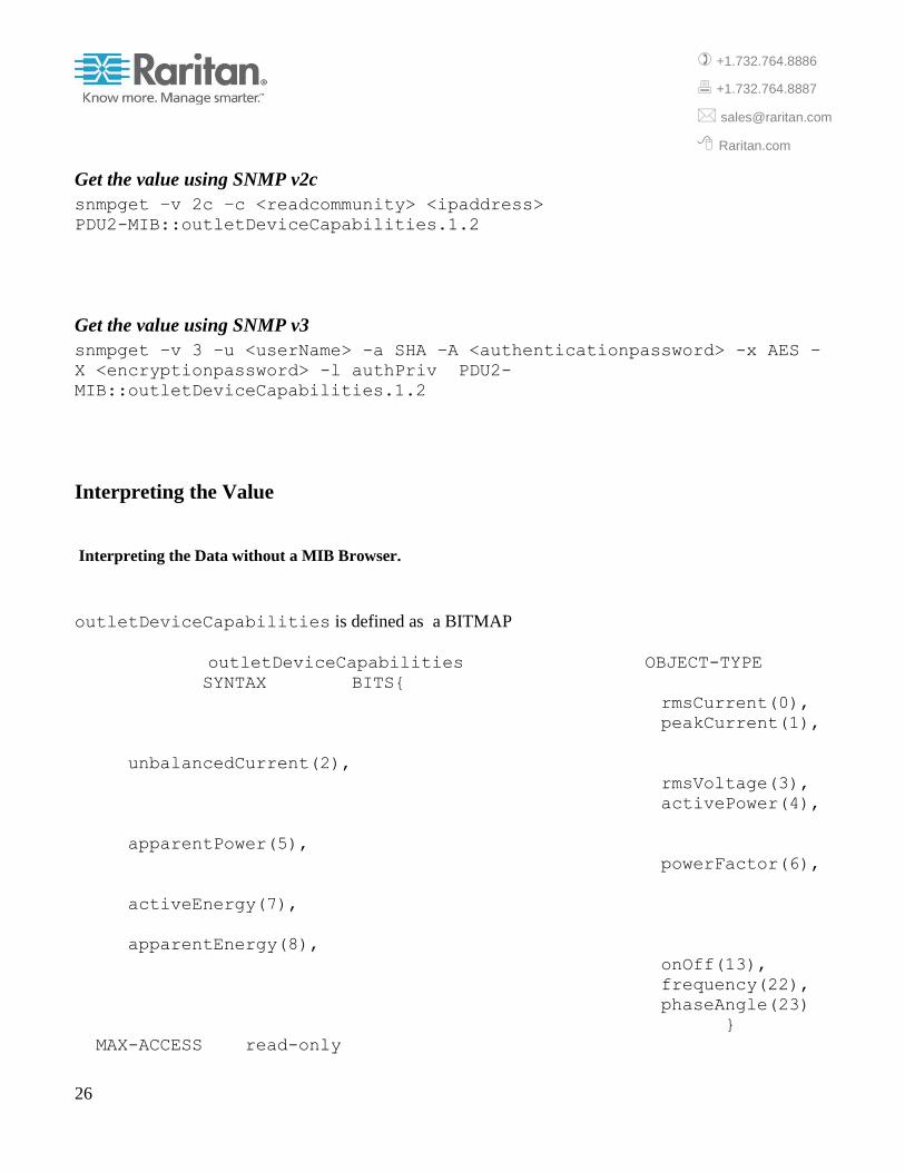
Interpreting the Value
Interpreting the Data without a MIB Browser.
outletDeviceCapabilities is defined as a BITMAP
outletDeviceCapabilities OBJECT-TYPE
SYNTAX BITS{
rmsCurrent(0),
peakCurrent(1),
unbalancedCurrent(2),
rmsVoltage(3),
activePower(4),
apparentPower(5),
powerFactor(6),
activeEnergy(7),
apparentEnergy(8),
onOff(13),
frequency(22),
phaseAngle(23)
}
MAX-ACCESS read-only

27
+1.732.764.8886
+1.732.764.8887
Raritan.com
STATUS current
DESCRIPTION
"A bit string which indicates which outlet sensors are
available."
::= { outletConfigurationEntry 10 }
The retrieved value is 9F.04.02.00.00.00 (hex)
This value must be examined to determine the bit positions that have a value of 1. Starting with the left
most bit which is at bit position 0, the bit positions 0,1,3,4,5,6,7, 13, 22 have a value of 1.
With reference to the definition of outletCapabilities, it can then be seen that the supported sensors for the
outlet are rmsCurrent, rmsVoltage, activePower, apparentPower, powerfactor, activeEnergy, onOff, and
frequency.
Interpreting the Data with a MIB Browser.
In this case the retrieved value will be interpreted and presented to the user.
(BITS) 9F.04.02.00.00.00 (hex) [rmsCurrent(0) | rmsVoltage(3) | activePower(4) | apparentPower(5) |
powerFactor(6) | activeEnergy(7) | onOff(13) | frequency(22)]
Switch an Outlet Off
Outlets can be switched on or off by setting the value of the switchingOperation object in the outletSwitchControlTable.
Example
Suppose the user wishes to switch outlet 9 off.
Determining the OID
The instance of the object is identified as shown below.
Object: switchingOperation
Table Index Clause: INDEX { pduId, outletId }
OID: 1.3.6.1.4.1.13742.6.3.3.3.1.10
28
+1.732.764.8886
+1.732.764.8887
Raritan.com
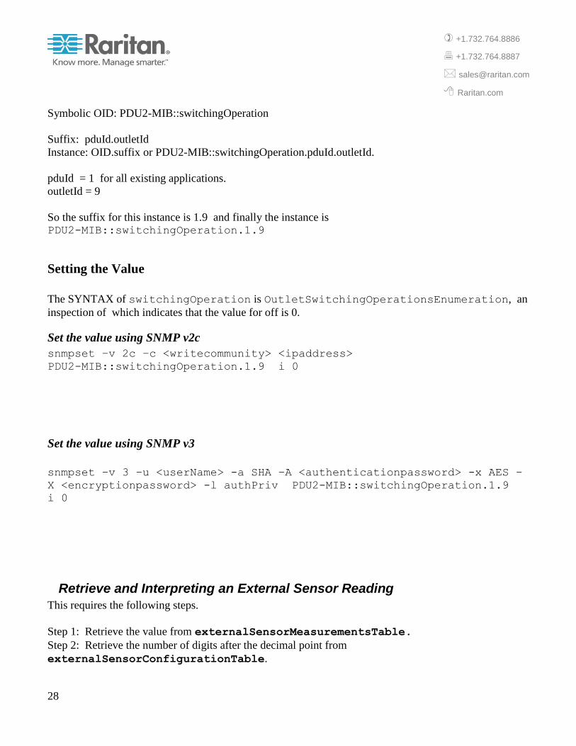
Symbolic OID: PDU2-MIB::switchingOperation
Suffix: pduId.outletId
Instance: OID.suffix or PDU2-MIB::switchingOperation.pduId.outletId.
pduId = 1 for all existing applications.
outletId = 9
So the suffix for this instance is 1.9 and finally the instance is PDU2-MIB::switchingOperation.1.9
Setting the Value
The SYNTAX of switchingOperation is OutletSwitchingOperationsEnumeration, an
inspection of which indicates that the value for off is 0.
Set the value using SNMP v2c
snmpset –v 2c –c <writecommunity> <ipaddress>
PDU2-MIB::switchingOperation.1.9 i 0
Set the value using SNMP v3
snmpset –v 3 –u <userName> -a SHA –A <authenticationpassword> -x AES –
X <encryptionpassword> -l authPriv PDU2-MIB::switchingOperation.1.9
i 0
Retrieve and Interpreting an External Sensor Reading
This requires the following steps.
Step 1: Retrieve the value from externalSensorMeasurementsTable.
Step 2: Retrieve the number of digits after the decimal point from
externalSensorConfigurationTable.

29
+1.732.764.8886
+1.732.764.8887
Raritan.com
Step 3: Retrieve the sensor units from externalSensorConfigurationTable.
Step 4: Sensor value = (Step 1 Value)/ 10( Step 2 value)
in units of Step 3 Value.
Example
Suppose the user wishes to retrieve the most recent value of the external sensor with sensor ID 11.
The steps are outlined here. For further details see 0.
Step 1: Retrieve the value
The required object is measurementsExternalSensorValue in the
externalSensorConfigurationTable..
Determine the OID
The instance of the object is identified as shown below.
Object: measurementsOutletSensorValue
Table Index Clause: INDEX { pduId, sensorId }
Symbolic OID: PDU2-MIB::measurementsExternalSensorValue.1.11
Get the value using SNMP v2c
snmpget –v 2c –c <readcommunity> <ipaddress>
PDU2-MIB::measurementsExternalSensorValue.1.11
Result:354
Get the value using SNMP v3
snmpget –v 3 –u <userName> -a SHA –A <authenticationpassword> -x AES –
X <encryptionpassword> -l authPriv PDU2-
MIB::measurementsExternalSensorValue.1.11
Result: 354

30
+1.732.764.8886
+1.732.764.8887
Raritan.com
Step 2: Retrieve the decimalDigits for this sensor
The required object is externalSensorDecimalDigits in the
ExtrenalSensorConfigurationTable.
Determine the OID
The instance of the object is identified as shown below.
Object: externalSensorDecimalDigits
Table Index Clause: INDEX { pduId, sensorId }
OID: 1.3.6.1.4.1.13742.6.3.5.4.1.7
Symbolic OID: PDU2-MIB::externalSensorDecimalDigits.1.11
Get the value using SNMP v2c
snmpget –v 2c –c <readcommunity> <ipaddress>
PDU2-MIB::externalSensorDecimalDigits.1.11
Result:1
Get the value using SNMP v3
snmpget –v 3 –u <userName> -a SHA –A <authenticationpassword> -x AES –
X <encryptionpassword> -l authPriv PDU2-
MIB::externalSensorDecimalDigits.1.11
Result: 1
Step 3: Retrieve the units for this sensor
The required object is externalSensorUnits in ExternalSensorConfigurationTable.
Determine the OID

31
+1.732.764.8886
+1.732.764.8887
Raritan.com
The instance of the object is identified as shown below.
Object: externalSensorUnits
Table Index Clause: INDEX { pduId, sensorId }
Symbolic OID: PDU2-MIB::externalSensorUnits.1.11
Get the value using SNMP v2c
snmpget –v 2c –c <readcommunity> <ipaddress> PDU2-
MIB::externalSensorUnits.1.11
Result:7
Get the value using SNMP v3
snmpget –v 3 –u <userName> -a SHA –A <authenticationpassword> -x AES –
X <encryptionpassword> -l authPriv PDU2-MIB::externalSensorUnits.1.11
Result: 7
This value must be interpreted using the TEXTUAL-CONVENTION SensorUnitsEnumeration
which indicates that 7 corresponds to °C.
Step 4: Scale the value
Sensor Value = 354/101 °C or 35.4 °C.
Set PDU Name
The PDU name can be changed by setting the value of the pduName object in the
unitConfigurationTable.

32
+1.732.764.8886
+1.732.764.8887
Raritan.com
Example
Suppose the user wishes to change pduName to “Rack1 2nd
PDU”.
Determining the OID
The instance of the object is identified as shown below.
Object: pduName
Table Index Clause: INDEX { pduId }
Symbolic OID of Instance: PDU2-MIB::pduName.1
Setting the Value
Set the value using SNMP v2c
snmpset –v 2c –c <writecommunity> <ipaddress>
PDU2-MIB::pduName.1 s “Rack1 2nd PDU”
Set the value using SNMP v3
snmpset –v 3 –u <userName> -a SHA –A <authenticationpassword> -x AES –
X <encryptionpassword> -l authPriv PDU2-MIB:: pduName.1 “Rack1 2nd
PDU”
Notification (Trap/Inform) Received when the Outlet Current exceeds the Upper Critical Threshold
The object is outletSensorStateChange defined in the MIB as
33
+1.732.764.8886
+1.732.764.8887
Raritan.com
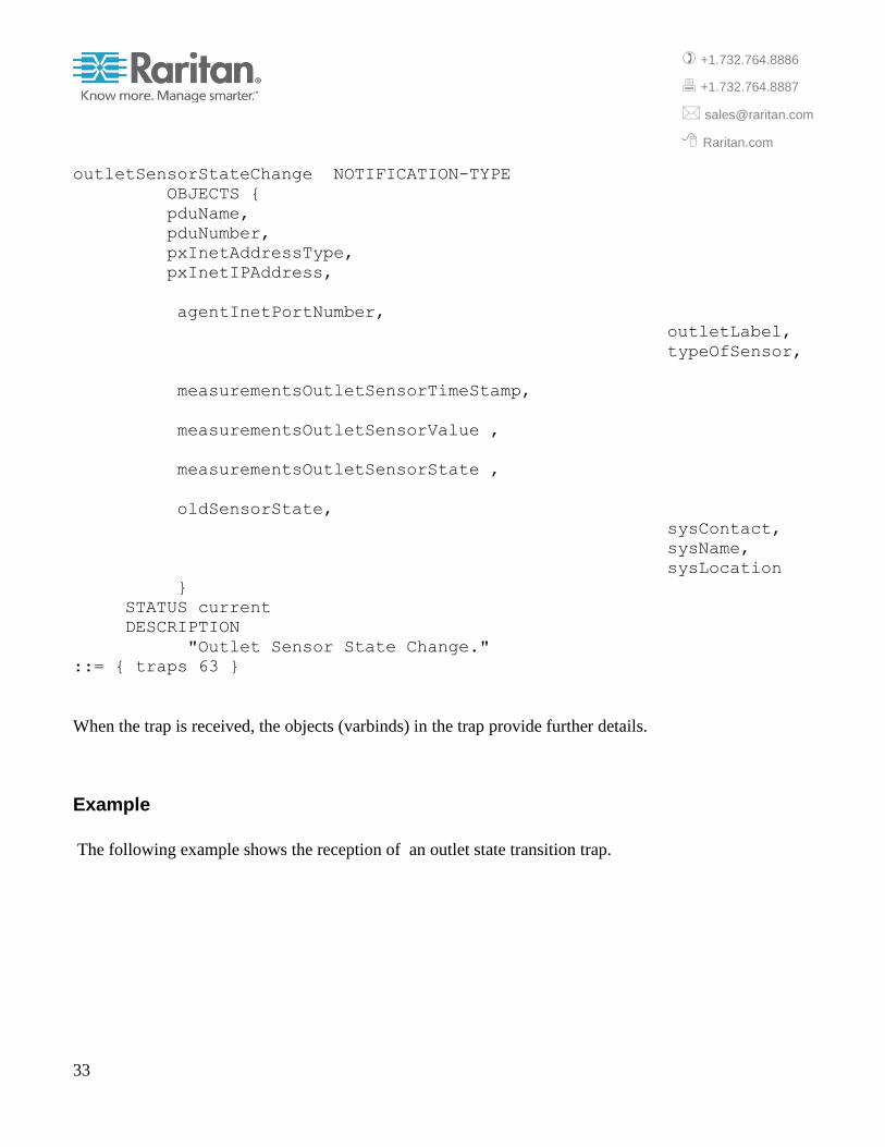
outletSensorStateChange NOTIFICATION-TYPE
OBJECTS {
pduName,
pduNumber,
pxInetAddressType,
pxInetIPAddress,
agentInetPortNumber,
outletLabel,
typeOfSensor,
measurementsOutletSensorTimeStamp,
measurementsOutletSensorValue ,
measurementsOutletSensorState ,
oldSensorState,
sysContact,
sysName,
sysLocation
}
STATUS current
DESCRIPTION
"Outlet Sensor State Change."
::= { traps 63 }
When the trap is received, the objects (varbinds) in the trap provide further details.
Example
The following example shows the reception of an outlet state transition trap.
34
+1.732.764.8886
+1.732.764.8887
Raritan.com
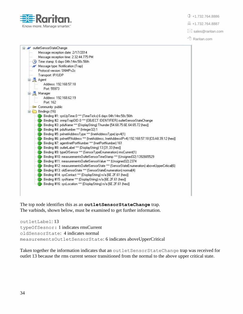
The top node identifies this as an outletSensorStateChange trap.
The varbinds, shown below, must be examined to get further information.
outletLabel: 13
typeOfSesnor: 1 indicates rmsCurrent
oldSensorState: 4 indicates normal
measurementsOutletSensorState: 6 indicates aboveUpperCritical
Taken together the information indicates that an outletSensorStateChange trap was received for
outlet 13 because the rms current sensor transitioned from the normal to the above upper critical state.