![Rabbies.pptx [Repaired]](https://static.fdocuments.us/doc/165x107/55cf8de6550346703b8c6c12/rabbiespptx-repaired.jpg)
Safety Recall Code: 69N2 - National Highway Traffic … vehicles repaired with this interim remedy...
37
The repair information in this document is intended for use only by skilled technicians who have the proper tools, equipment and training to correctly and safely maintain your vehicle. These procedures are not intended to be attempted by “do-it-yourselfers,” and you should not assume this document applies to your vehicle, or that your vehicle has the condition described. To determine whether this information applies, contact an authorized Audi dealer. 2017 Audi of America, Inc. and Audi Canada. All Rights Reserved. March 2017 69N2 Page 1 of 35 Safety Recall Code: 69N2 Subject TAKATA PSDI-5 Driver Frontal Airbag Inflator Release Date March 8, 2017 Affected Vehicles U.S.A. & CANADA: Certain 2006-2013 MY Audi Vehicles equipped with a Takata PSDI-5 driver frontal airbag Check Campaigns/Actions screen in Elsa on the day of repair to verify that a VIN qualifies for repair under this action. Elsa is the only valid campaign inquiry & verification source. Campaign status must show “open.” If Elsa shows other open action(s), inform your customer so that the work can also be completed at the same time the vehicle is in the workshop for this campaign. Takata Recall Priority Groups and Repair Rollout This recall is being managed according to the requirements mandated by the NHTSA in the Third Amendment to the Coordinated Remedy Order. Transport Canada is following the same requirements.Vehicles affected by this recall fall into the following priority groups established by the NHTSA as shown below: Priority Group Sufficient Supply & Remedy Launch Deadlines Priority Group 4 March 31, 2017 Priority Group 5 June 30, 2017 Priority Group 6 September 30, 2017 Additional information about the NHTSA priority groups and the Takata recall can be found at www.safercar.gov or www.tc.gc.ca/takata-recalls and www.tc.gc.ca/rappels-takata. Problem Description Takata has reported that the driver frontal airbag inflator could potentially rupture (due to propellant degradation occurring after long-term exposure to absolute high humidity and temperature cycling) if the vehicle is involved in a crash where the frontal airbags are designed to deploy. In the event of an inflator rupture, metal fragments could pass through the airbag cushion material, which may result in serious injury or death to vehicle occupants. Corrective Action Perform an interim repair to replace the driver frontal airbag inflator with a newly manufactured version. The National Highway Traffic Safety Administration (NHTSA) has concluded, based on information it has collected, that the age of the inflator, temperature cycling, and environmental moisture are likely the root cause of rupturing. Therefore, replacing the older inflator with a newer version reduces the safety risk associated with the vehicle until a final remedy is available. All vehicles repaired with this interim remedy will be offered a free-of-charge final remedy at a future date. Customers will be notified again via first-class mail when the final remedy is available. Precautions Owners are advised to have the inflator replaced as soon as possible and not wait for the final remedy. If a vehicle with a recalled Takata airbag inflator is involved in a crash with airbag deployment, the inflator could rupture and send shrapnel toward everyone in the vehicle. People have been killed and seriously injured by this defect. Owners are also advised to inform all other drivers and passengers of an affected vehicle about this important information. Critical Information Inflator part supply is limited industry-wide and will continue to be so due to supplier capacity constraints and demand from all vehicle manufacturers. Due to limited industry supply and climate variances the NHTSA has created priority groups to help ensure the highest priority vehicles are remedied first. These factors are the age of the inflator (with older presenting a greater risk), geographic registered history of the
-
Upload
trinhtuong -
Category
Documents
-
view
214 -
download
1
Transcript of Safety Recall Code: 69N2 - National Highway Traffic … vehicles repaired with this interim remedy...

The repair information in this document is intended for use only by skilled technicians who have the proper tools, equipment and training to correctly and safely maintain your vehicle. These procedures are not intended to be attempted by “do-it-yourselfers,” and you should not assume this document applies to your vehicle, or that your vehicle has the condition described. To determine whether this information applies, contact an authorized Audi dealer. 2017 Audi of America, Inc. and Audi Canada. All Rights Reserved.
March 2017 69N2 Page 1 of 35
Safety Recall Code: 69N2
Subject TAKATA PSDI-5 Driver Frontal Airbag Inflator
Release Date March 8, 2017
Affected Vehicles
U.S.A. & CANADA: Certain 2006-2013 MY Audi Vehicles equipped with a Takata PSDI-5 driver frontal airbag
Check Campaigns/Actions screen in Elsa on the day of repair to verify that a VIN qualifies for repair under this action. Elsa is the only valid campaign inquiry & verification source.
Campaign status must show “open.”
If Elsa shows other open action(s), inform your customer so that the work can also be completed at the same time the vehicle is in the workshop for this campaign.
Takata Recall Priority
Groups and Repair Rollout
This recall is being managed according to the requirements mandated by the NHTSA in the Third Amendment to the Coordinated Remedy Order. Transport Canada is following the same requirements.Vehicles affected by this recall fall into the following priority groups established by the NHTSA as shown below:
Priority Group Sufficient Supply & Remedy Launch Deadlines
Priority Group 4 March 31, 2017 Priority Group 5 June 30, 2017 Priority Group 6 September 30, 2017
Additional information about the NHTSA priority groups and the Takata recall can be found at www.safercar.gov or www.tc.gc.ca/takata-recalls and www.tc.gc.ca/rappels-takata.
Problem Description
Takata has reported that the driver frontal airbag inflator could potentially rupture (due to propellant degradation occurring after long-term exposure to absolute high humidity and temperature cycling) if the vehicle is involved in a crash where the frontal airbags are designed to deploy. In the event of an inflator rupture, metal fragments could pass through the airbag cushion material, which may result in serious injury or death to vehicle occupants.
Corrective Action
Perform an interim repair to replace the driver frontal airbag inflator with a newly manufactured version.
The National Highway Traffic Safety Administration (NHTSA) has concluded, based on information it has collected, that the age of the inflator, temperature cycling, and environmental moisture are likely the root cause of rupturing. Therefore, replacing the older inflator with a newer version reduces the safety risk associated with the vehicle until a final remedy is available.
All vehicles repaired with this interim remedy will be offered a free-of-charge final remedy at a future date. Customers will be notified again via first-class mail when the final remedy is available.
Precautions Owners are advised to have the inflator replaced as soon as possible and not wait for the final remedy. If a vehicle with a recalled Takata airbag inflator is involved in a crash with airbag deployment, the inflator could rupture and send shrapnel toward everyone in the vehicle. People have been killed and seriously injured by this defect.
Owners are also advised to inform all other drivers and passengers of an affected vehicle about this important information.
Critical Information
Inflator part supply is limited industry-wide and will continue to be so due to supplier capacity constraints and demand from all vehicle manufacturers.
Due to limited industry supply and climate variances the NHTSA has created priority groups to help ensure the highest priority vehicles are remedied first. These factors are the age of the inflator (with older presenting a greater risk), geographic registered history of the

The information in this document is intended for use only by skilled technicians who have the proper tools, equipment and training to correctly and safely maintain your vehicle. These procedures are not intended to be attempted by “do-it-yourselfers,” and you should not assume this document applies to your vehicle, or that your vehicle has the condition described. To determine whether this information applies, contact an authorized Volkswagen dealer. 2017 Volkswagen Group of America, Inc. and Volkswagen Canada. All Rights Reserved.
March 2017 69N2 Page 2 of 35
vehicle (with prolonged exposure to high absolute humidity (Zone A) presenting a greater risk), and location of the Takata inflator in the vehicle (driver, passenger or both).
The NHTSA has created the priority groups based on testing, field experience, and research. Older inflators in vehicles that have experienced prolonged exposure to hot and humid conditions pose a much greater risk of rupturing. Accordingly, NHTSA has ordered manufacturers to replace inflators in older vehicles that are most likely to have been exposed to prolonged hot and humid conditions first.
Part allocations will be prioritized to ensure availability for customer vehicles that fall within the highest-risk locations for the priority groups.
Dealers are expected to manage the limited allocations they receive carefully and schedule customers accordingly to ensure that the highest-risk customer vehicles are repaired promptly and without unreasonable delay.
Due to limited parts supply and focus on highest-risk priority groups, dealers should not expect to keep stock on hand at all times. Rather, dealers should ensure their allocated parts are installed on the priority group vehicles that are released for repair.
The chart below can be used to help identify which priority group is released for repair. The criteria for each VIN may be found in Elsa in the Campaigns/Actions screen. As new priority groups are released for repair, this will be updated. Please ensure that you are using the latest version of the circular available in Elsa.
Criteria (Priority Group)
Criteria Part Number P4 P5 P6
01 8P0 898 201 Released Restricted Restricted
02 8H0 898 201 Released Restricted Restricted
Released – Perform repair without delay
Restricted – Advise customer that parts are not released for their priority group as defined by NHTSA and may be available by the dates above in the Takata Recall Priority Groups and Repair Rollout section.
Parts were allocated prior to campaign launch and repair availability for each priority group. You may not have received an allocation if your dealership was projected to not have affected vehicles in your area.
Future replenishments/allocations will be based on paid SAGA claims for priority groups that have been released for repair with the respective part number. These replenishments/allocations are expected to be sent weekly.
All SAGA claims will be stopped for review to ensure the appropriate priority level.
Do not call a Parts Specialist to request additional parts. These requests cannot and will not be fulfilled.
Code Visibility On or about March 8, 2017 affected vehicles will be listed on the Inventory Vehicle Open Campaign Action report under My Dealership Reports (found on www.accessaudi.com & OMD Web). A list will not be posted for dealers who do not have any affected vehicles.
On or about March 8, 2017, this campaign code will show open on affected vehicles in Elsa.
On or about March 8, 2017, affected vehicles will be identified with this campaign code in the VIN Lookup tool at www.audiusa.com and on the NHTSA VIN lookup tool at www.safercar.gov.

The information in this document is intended for use only by skilled technicians who have the proper tools, equipment and training to correctly and safely maintain your vehicle. These procedures are not intended to be attempted by “do-it-yourselfers,” and you should not assume this document applies to your vehicle, or that your vehicle has the condition described. To determine whether this information applies, contact an authorized Volkswagen dealer. 2017 Volkswagen Group of America, Inc. and Volkswagen Canada. All Rights Reserved.
March 2017 69N2 Page 3 of 35
Owner Notification
Owner notification will take place for vehicles in each priority group as shown in the chart below. Owner letter examples are included in this bulletin for your reference.
Priority Group Sufficient Supply & Remedy Launch Deadlines
Priority Group 4 March 31, 2017 Priority Group 5 June 30, 2017 Priority Group 6 September 30, 2017
Additional Information
Please alert everyone in your dealership about this action, including Sales, Service, Parts and Accounting personnel. Contact Warranty if you have any questions.
IMPORTANT REMINDER ON VEHICLES AFFECTED BY SAFETY & COMPLIANCE RECALLS
New Vehicles in Dealer Inventory: It is a violation of Federal law for a dealer to deliver a new motor vehicle or any new or used item of motor vehicle equipment (including a tire) covered by this notification under a sale or lease until the defect or noncompliance is remedied. By law, dealers must correct, prior to delivery for sale or lease, any vehicle that fails to comply with an applicable Federal Motor Vehicle Safety Standard or that contains a defect relating to motor vehicle safety.
Pre-Owned Vehicles in Dealer Inventory: Dealers should not deliver any pre-owned vehicles in their inventory which are involved in a safety or compliance recall until the defect has been remedied.
Dealers must ensure that every affected inventory vehicle has this campaign completed before delivery to consumers.

The repair information in this document is intended for use only by skilled technicians who have the proper tools, equipment and training to correctly and safely maintain your vehicle. These procedures are not intended to be attempted by “do-it-yourselfers,” and you should not assume this document applies to your vehicle, or that your vehicle has the condition described. To determine whether this information applies, contact an authorized Audi dealer. 2017 Audi of America, Inc. and Audi Canada. All Rights Reserved.
March 2017 69N2 Page 4 of 35
Claim Entry Instructions
After campaign has been completed, enter claim as soon as possible to help prevent work from being duplicated elsewhere. Attach the Elsa screen print showing action open on the day of repair to the repair order.
If customer refused campaign work:
U.S. dealers: Submit the request through Audi Warranty Online under the Campaigns/Update option.
Canada dealers: Fax repair order to Warranty at (905) 428-4811.
Service Number 69N2
Damage Code 0099
Parts Vendor Code 002
Claim Type Sold vehicle: 7 10
Unsold vehicle: 7 90
Causal Indicator *Mark airbag inflator as causal part
Vehicle Wash/Loaner Do not claim wash/loaner under this action
Vehicles have more than one criteria. Complete and claim all applicable criteria on one claim.
Criteria I.D. 01, 8H and P4 or
01, 8P, and P4
Install new airbag inflator. Labor operation: 6958 5599 85 T.U.
Quantity Part Number Description 1.00 8P0898201* Airbag Inflator
Criteria I.D. 02, 8H, and P4
Install new airbag inflator. Labor operation: 6958 5599 85 T.U.
Quantity Part Number Description 1.00 8H0898201* Airbag Inflator
Criteria I.D. P5, 01, and 8H
P5, 01, and 8P
P5, 02, and 8H
P6, 01, and 8P
Repair not released

The repair information in this document is intended for use only by skilled technicians who have the proper tools, equipment and training to correctly and safely maintain your vehicle. These procedures are not intended to be attempted by “do-it-yourselfers,” and you should not assume this document applies to your vehicle, or that your vehicle has the condition described. To determine whether this information applies, contact an authorized Audi dealer. 2017 Audi of America, Inc. and Audi Canada. All Rights Reserved.
March 2017 69N2 Page 5 of 35
Customer Letter Example (USA)
This notice applies to your vehicle: <VIN>
NHTSA: 16V079
Subject: Safety Recall 69N2 - Takata PSDI-5 Driver Frontal Airbag Inflator Certain 2006-2013 Model Year Audi Vehicles equipped with a Takata PSDI-5 Driver Frontal Airbag
Dear Audi Owner,
This notice is sent to you in accordance with the National Traffic and Motor Vehicle Safety Act. Audi has decided that a defect, which relates to motor vehicle safety, exists in certain 2006-2013 model year Audi vehicles equipped with a Takata PSDI-5 driver frontal airbag. Our records show that you are the owner of a vehicle affected by this action.
What is the issue? Takata has reported that the driver frontal airbag inflator could potentially rupture (due to propellant degradation occurring after long-term exposure to absolute high humidity and temperature cycling) if the vehicle is involved in a crash where the frontal airbags are designed to deploy. In the event of an inflator rupture, metal fragments could pass through the airbag cushion material, which may result in serious injury or death to vehicle occupants.
What will we do? To address this defect, your authorized Audi dealer will perform an interim repair to replace the driver frontal airbag inflator with a newly manufactured version.
The National Highway Traffic Safety Administration (NHTSA) has concluded, based on information it has collected, that the age of the inflator, temperature cycling, and environmental moisture are likely the root cause of rupturing. Therefore, replacing the older inflator with a newer version reduces the safety risk associated with the vehicle until a final remedy is available.
This work will take about an hour to complete and will be performed for you free of charge.
All vehicles repaired with this interim remedy will be offered a free-of-charge final remedy at a future date. We will notify you again via first-class mail when the final remedy is available.
PRECAUTIONS YOU SHOULD TAKE
Do not delay in having this recall repair performed. Make an appointment with your authorized dealer to have the recalled Takata airbag inflator in your vehicle replaced as soon as possible. If a vehicle with a recalled Takata airbag inflator is involved in a crash with airbag deployment, the inflator could rupture and send shrapnel toward everyone in the vehicle. People have been killed and seriously injured by this defect.
If you are not the only driver of this vehicle, please advise all other drivers and passengers of this important information.
What should you do? Please contact your authorized Audi dealer without delay to schedule this recall repair. For your convenience, you can also visit www.audiusa.com and click on the “Find a Dealer” link to locate a dealer near you and schedule this service.
Lease vehicles and address changes
If you are the lessor and registered owner of the vehicle identified in this action, the law requires you to forward this letter immediately via first-class mail to the lessee within ten (10) days of receipt. If you have changed your address or sold the vehicle, please fill out the enclosed prepaid Owner Reply card and mail it to us so we can update our records.
Can we assist you further?
If your authorized Audi dealer fails or is unable to complete this work free of charge within a reasonable time, please contact Audi Customer Experience at 1-800-253-2834 or via our “Contact Us” page at www.audiusa.com.
Checking your vehicle for open Recalls and Service Campaigns
To check your vehicle’s eligibility for repair under this or any other recall/service campaign, please visit the Recall/Service Campaign Lookup tool at www.audiusa.com and enter your Vehicle Identification Number (VIN).
If you still cannot obtain satisfaction, you may file a complaint with: The Administrator, National Highway Traffic Safety Administration, 1200 New Jersey Avenue, SE., Washington, DC 20590; or call the toll-free Vehicle Safety Hotline at 1-888-327-4236 (TTY: 1-800-424-9153); or go to http://www.safercar.gov.
We apologize for any inconvenience this matter may cause; however we are taking this action to help ensure your safety and continued satisfaction with your vehicle.
Sincerely,
Audi Customer Protection

The repair information in this document is intended for use only by skilled technicians who have the proper tools, equipment and training to correctly and safely maintain your vehicle. These procedures are not intended to be attempted by “do-it-yourselfers,” and you should not assume this document applies to your vehicle, or that your vehicle has the condition described. To determine whether this information applies, contact an authorized Audi dealer. 2017 Audi of America, Inc. and Audi Canada. All Rights Reserved.
March 2017 69N2 Page 6 of 35
Customer Letter Example (CANADA)
This notice applies to your vehicle: <VIN>
Subject: Safety Recall 69N2 - Takata PSDI-5 Driver Frontal Airbag Inflator Certain 2006-2013 Model Year Audi Vehicles equipped with a Takata PSDI-5 Driver Frontal Airbag
Dear Audi Owner,
This notice is sent to you in accordance with the requirements of the Motor Vehicle Safety Act. Audi has decided that a defect, which relates to motor vehicle safety, exists in certain 2006-2013 model year Audi vehicles equipped with a Takata PSDI-5 driver frontal airbag. Our records show that you are the owner of a vehicle affected by this action.
What is the issue? Takata has reported that the driver frontal airbag inflator could potentially rupture (due to propellant degradation occurring after long-term exposure to absolute high humidity and temperature cycling) if the vehicle is involved in a crash where the frontal airbags are designed to deploy. In the event of an inflator rupture, metal fragments could pass through the airbag cushion material, which may result in serious injury or death to vehicle occupants.
What will we do? To address this defect, your authorized Audi dealer will perform an interim repair to replace the driver frontal airbag inflator with a newly manufactured version.
The United States National Highway Traffic Safety Administration (NHTSA) has concluded, based on information it has collected, that the age of the inflator, temperature cycling, and environmental moisture are likely the root cause of rupturing. Therefore, replacing the older inflator with a newer version reduces the safety risk associated with the vehicle until a final remedy is available.
This work will take about an hour to complete and will be performed for you free of charge.
All vehicles repaired with this interim remedy will be offered a free-of-charge final remedy at a future date. We will notify you again via first-class mail when the final remedy is available.
PRECAUTIONS YOU SHOULD TAKE
Do not delay in having this recall repair performed. Make an appointment with your authorized dealer to have the recalled Takata airbag inflator in your vehicle replaced as soon as possible. If a vehicle with a recalled Takata airbag inflator is involved in a crash with airbag deployment, the inflator could rupture and send shrapnel toward everyone in the vehicle. People have been killed and seriously injured by this defect.
If you are not the only driver of this vehicle, please advise all other drivers and passengers of this important information.
What should you do? Please contact your authorized Audi dealer without delay to schedule this recall repair.
Lease vehicles and address changes
If you are the lessor and registered owner of the vehicle identified in this action, the law requires you to forward this letter immediately via first-class mail to the lessee within ten (10) days of receipt. If you have changed your address or sold the vehicle, please fill out the enclosed prepaid Owner Reply card and mail it to us so we can update our records.
Can we assist you further?
If your authorized Audi dealer fails or is unable to complete this work free of charge within a reasonable time, please contact Audi Customer Relations Monday through Friday from 8AM to 8PM EST at 1-800-822-2834 or via our “Contact Audi Canada” page at www.audi.ca.
We apologize for any inconvenience this matter may cause; however we are taking this action to help ensure your safety and continued satisfaction with your vehicle.
Sincerely,
Audi Customer Protection
The repair information in this document is intended for use only by skilled technicians who have the proper tools, equipment and training to correctly and safely maintain your vehicle. These procedures are not intended to be attempted by “do-it-yourselfers,” and you should not assume this document applies to your vehicle, or that your vehicle has the condition described. To determine whether this information applies, contact an authorized Audi dealer. 2017 Audi of America, Inc. and Audi Canada. All Rights Reserved.
March 2017 69N2 Page 7 of 35
Campaign Work Procedure 69N2 Safety Recall
WARNING
Risk of injury. Refer to “Warning and Safety Precautions”, found in Appendix A at the end of this document.
The driver frontal airbag inflator could potentially rupture (due to propellant degradation occurring after long-term exposure to absolute high humidity and temperature cycling. In the event of an inflator rupture, in very rare cases metal fragments could pass through the airbag cushion material, which may result in serious injury or death.
NOTE
Damages resulting from improper repair or failure to follow these work instructions are the dealer’s responsibility and are not eligible for reimbursement under this action.
This procedure must be read in its entirety prior to performing the repair.
Due to variations in vehicle equipment and options, the steps/illustrations in this work procedure may not identically match all affected vehicles.
Required Parts
Criteria Quantity Part Number Part Description
01 1 8P0898201 Airbag Inflator Kit (includes inflator, inflator nuts, horn ring bolts and return instructions). 02 1 8H0898201
Required Safety Equipment
Ear Protection (locally sourced)

The repair information in this document is intended for use only by skilled technicians who have the proper tools, equipment and training to correctly and safely maintain your vehicle. These procedures are not intended to be attempted by “do-it-yourselfers,” and you should not assume this document applies to your vehicle, or that your vehicle has the condition described. To determine whether this information applies, contact an authorized Audi dealer. 2017 Audi of America, Inc. and Audi Canada. All Rights Reserved.
March 2017 69N2 Page 8 of 35
Face Shield (locally sourced)
Required Tools
ESD Worksurface - VAS 6613

The repair information in this document is intended for use only by skilled technicians who have the proper tools, equipment and training to correctly and safely maintain your vehicle. These procedures are not intended to be attempted by “do-it-yourselfers,” and you should not assume this document applies to your vehicle, or that your vehicle has the condition described. To determine whether this information applies, contact an authorized Audi dealer. 2017 Audi of America, Inc. and Audi Canada. All Rights Reserved.
March 2017 69N2 Page 9 of 35
Bar Code Scanner – VAS6161/1
Airbag Support - T10568
VAS6150D - Diagnostic Tester (or equivalent)

The repair information in this document is intended for use only by skilled technicians who have the proper tools, equipment and training to correctly and safely maintain your vehicle. These procedures are not intended to be attempted by “do-it-yourselfers,” and you should not assume this document applies to your vehicle, or that your vehicle has the condition described. To determine whether this information applies, contact an authorized Audi dealer. 2017 Audi of America, Inc. and Audi Canada. All Rights Reserved.
March 2017 69N2 Page 10 of 35
VAG1410 – Torque Wrench (or equivalent)
Required Work Environment
WARNING
Risk of injury. It is critical that a clean, uncongested work environment is utilized during the inflator replacement procedure. Extra tools, debris, etc… in the blast area of an airbag impose a danger in the event an airbag were to deploy. Ensure there are no loose components in the blast area of the airbag.
NOTE
The work area must be in the vicinity of the scan tool and the vehicle in order to properly complete this procedure.
Workbench that will support a vice.
Work surface free of unnecessary tools, equipment and debris.

The repair information in this document is intended for use only by skilled technicians who have the proper tools, equipment and training to correctly and safely maintain your vehicle. These procedures are not intended to be attempted by “do-it-yourselfers,” and you should not assume this document applies to your vehicle, or that your vehicle has the condition described. To determine whether this information applies, contact an authorized Audi dealer. 2017 Audi of America, Inc. and Audi Canada. All Rights Reserved.
March 2017 69N2 Page 11 of 35
Repair Instruction
Section A - Check for Previous Repair
Enter the VIN in Elsa and proceed to the
“Campaign/Action” screen.
TIP
On the date of repair, print this screen and keep a copy with the repair order.
Confirm the Campaign/Action is open <arrow 1>.
If the status is closed, no further work is required.
Note the Applicable Criteria ID <arrow 2> for use in determining the correct work to be done and corresponding parts associated. Proceed to Section B

The repair information in this document is intended for use only by skilled technicians who have the proper tools, equipment and training to correctly and safely maintain your vehicle. These procedures are not intended to be attempted by “do-it-yourselfers,” and you should not assume this document applies to your vehicle, or that your vehicle has the condition described. To determine whether this information applies, contact an authorized Audi dealer. 2017 Audi of America, Inc. and Audi Canada. All Rights Reserved.
March 2017 69N2 Page 12 of 35
Section B – Gas Generator Identification (all vehicles)
WARNING
Risk of injury. People in the immediate vicinity of the workplace must be protected from possible noise and projectiles.
Pyrotechnic components can trigger unintentionally.
In the event of unintentional deployment:
o Single-stage generators: allow airbag to cool down completely. Wait at least 10 minutes before handling.
o Two-stage generators: wait for second airbag ignition. Allow airbag to cool down completely. Wait at least 10 minutes before handling.
https://audi-academy.kzoplatform.com/player/medium/811705205740540937
Use the QR code or the link to view a video detailing the repair process prior to performing the repair.
NOTE
Prior to beginning work, all parts and tools are to be placed on the ESD table mat.
The workstation must be in the vicinity of the vehicle.
Assemble ESD workplace -VAS 6613- <1, 2, 3, and 4>.
Plug ESD workplace into a wall socket using plug <1>.
NOTE
The wall socket or extension cord must have a sufficient ground.

The repair information in this document is intended for use only by skilled technicians who have the proper tools, equipment and training to correctly and safely maintain your vehicle. These procedures are not intended to be attempted by “do-it-yourselfers,” and you should not assume this document applies to your vehicle, or that your vehicle has the condition described. To determine whether this information applies, contact an authorized Audi dealer. 2017 Audi of America, Inc. and Audi Canada. All Rights Reserved.
March 2017 69N2 Page 13 of 35
Clamp Airbag Support T10568 <2> into the vice.
Connect crocodile clip <1> to airbag support <2> and ESD workplace -VAS 6613-.
Ensure ODIS is updated to the latest version.
Connect vehicle diagnostic tester to the vehicle.
Select Start Diagnosis function and identify vehicle.
After identification of control units, Guided Fault Finding is started automatically.
Follow the instructions on screen.

The repair information in this document is intended for use only by skilled technicians who have the proper tools, equipment and training to correctly and safely maintain your vehicle. These procedures are not intended to be attempted by “do-it-yourselfers,” and you should not assume this document applies to your vehicle, or that your vehicle has the condition described. To determine whether this information applies, contact an authorized Audi dealer. 2017 Audi of America, Inc. and Audi Canada. All Rights Reserved.
March 2017 69N2 Page 14 of 35
Select the “Test plan” tab <1>.
Select “Select self test…” <2>.
Open the “Build status documentation” dropdown <3>.
Highlight “Airbag” <4>.
Select “Attach to the test plan <5>.

The repair information in this document is intended for use only by skilled technicians who have the proper tools, equipment and training to correctly and safely maintain your vehicle. These procedures are not intended to be attempted by “do-it-yourselfers,” and you should not assume this document applies to your vehicle, or that your vehicle has the condition described. To determine whether this information applies, contact an authorized Audi dealer. 2017 Audi of America, Inc. and Audi Canada. All Rights Reserved.
March 2017 69N2 Page 15 of 35
Highlight the “Airbag” test plan <1>.
Select “Perform test…” <2>.

The repair information in this document is intended for use only by skilled technicians who have the proper tools, equipment and training to correctly and safely maintain your vehicle. These procedures are not intended to be attempted by “do-it-yourselfers,” and you should not assume this document applies to your vehicle, or that your vehicle has the condition described. To determine whether this information applies, contact an authorized Audi dealer. 2017 Audi of America, Inc. and Audi Canada. All Rights Reserved.
March 2017 69N2 Page 16 of 35
Scanning the bar code during this test plan step calibrates the scanner to avoid error messages.
Scanning the calibrating bar code may not have to be done every time. Only when the scanner requires calibration. You will know if the scanner needs calibrating if the scanner does not scan the inflator’s bar code.
If the inflator bar code cannot be scanned, then print out the barcode shown below and scan the printout.
After calibrating the scanner, select “Complete/Continue”

The repair information in this document is intended for use only by skilled technicians who have the proper tools, equipment and training to correctly and safely maintain your vehicle. These procedures are not intended to be attempted by “do-it-yourselfers,” and you should not assume this document applies to your vehicle, or that your vehicle has the condition described. To determine whether this information applies, contact an authorized Audi dealer. 2017 Audi of America, Inc. and Audi Canada. All Rights Reserved.
March 2017 69N2 Page 17 of 35
Put the wrist strap from the ESD workplace on your wrist.
CAUTION
The white dots on the wrist strap must be against the skin.
NOTE
There are two types of inflator. One version is “with vibration absorption” and one is “without vibration absorption”.
Airbags with vibration absorption may be identified by the word “TILGER” on the label found on the airbag.
NOTE
In the event an airbag had previously been replaced, the replacement airbag may have an inflator WITH the vibration absorber. If this situation is encountered, the inflator WITH vibration absorption MUST be installed:
Repackage the previously scanned inflator and return to the parts department.
Acquire the correct inflator from the parts department.
Scan the new inflator using the GFF test plan.
Install the new inflator, following the “Inflator versions WITH vibration absorption” instructions.

The repair information in this document is intended for use only by skilled technicians who have the proper tools, equipment and training to correctly and safely maintain your vehicle. These procedures are not intended to be attempted by “do-it-yourselfers,” and you should not assume this document applies to your vehicle, or that your vehicle has the condition described. To determine whether this information applies, contact an authorized Audi dealer. 2017 Audi of America, Inc. and Audi Canada. All Rights Reserved.
March 2017 69N2 Page 18 of 35
Place the new inflator on the ESD mat.
Scan the bar code of the new inflator at a distance of about 15 cm.
CAUTION
Ensure the correct inflator is scanned and installed into the vehicle.
Criteria Part Number
01 8P0898201
02 8H0898201
NOTE
The photo is for reference only. The inflator that is installed may be either a single stage or dual stage inflator.
Once the new inflator has been successfully scanned, press “Accept”
NOTE
Compare the scanned value with the value shown above the bar code on the new inflator.
If there is a discrepancy, manually enter the value from the new inflator in the input field.
If no value appears, recalibrate the scanner.

The repair information in this document is intended for use only by skilled technicians who have the proper tools, equipment and training to correctly and safely maintain your vehicle. These procedures are not intended to be attempted by “do-it-yourselfers,” and you should not assume this document applies to your vehicle, or that your vehicle has the condition described. To determine whether this information applies, contact an authorized Audi dealer. 2017 Audi of America, Inc. and Audi Canada. All Rights Reserved.
March 2017 69N2 Page 19 of 35
Select option 1 indicating that the Driver side inflator was replaced.
After selecting option 1, a valid GeKo ID will need to be entered in order to upload the new inflator identification.
Continue to Section C.

The repair information in this document is intended for use only by skilled technicians who have the proper tools, equipment and training to correctly and safely maintain your vehicle. These procedures are not intended to be attempted by “do-it-yourselfers,” and you should not assume this document applies to your vehicle, or that your vehicle has the condition described. To determine whether this information applies, contact an authorized Audi dealer. 2017 Audi of America, Inc. and Audi Canada. All Rights Reserved.
March 2017 69N2 Page 20 of 35
Section C – Battery Disconnect
A3 Procedure
Battery in Engine Compartment:
WARNING
Accident risk. When working on pyrotechnic components (such as airbags and belt tensioners), the battery must be disconnected with the ignition switched ON.
NOTE
Before disconnecting the battery, it is recommended to record the customer’s radio presets so they can be restored before returning vehicle to the customer.
Turn ON the ignition.
Move the driver seat to the most rearward position.
Fully recline driver seat.
CAUTION
Reclining the driver seat before disconnecting the battery allows for additional safety in the event Terminal 15 power is not restored when reconnecting the battery at the end of the repair.
Remove battery cover <1> by pressing release button in direction of <arrow>.
Make sure the ignition is turned ON.
Loosen the nut <1>.
Remove and isolate the battery ground cable terminal <2> from the battery terminal.
Continue to Section D.

The repair information in this document is intended for use only by skilled technicians who have the proper tools, equipment and training to correctly and safely maintain your vehicle. These procedures are not intended to be attempted by “do-it-yourselfers,” and you should not assume this document applies to your vehicle, or that your vehicle has the condition described. To determine whether this information applies, contact an authorized Audi dealer. 2017 Audi of America, Inc. and Audi Canada. All Rights Reserved.
March 2017 69N2 Page 21 of 35
Battery in Luggage Compartment:
WARNING
Accident risk. When working on pyrotechnic components (such as airbags and belt tensioners), the battery must be disconnected with the ignition switched ON.
NOTE
Before disconnecting the battery, it is recommended to record the customer’s radio presets so they can be restored before returning vehicle to the customer.
Turn ON the ignition.
Move the driver seat to the most rearward position.
Fully recline the driver seat.
CAUTION
Reclining the driver seat before disconnecting the battery allows for additional safety in the event Terminal 15 power is not restored when reconnecting the battery at the end of the repair.
Remove the rear molded insert <3>.
Remove the battery cover <arrow>.
Remove the molded insert on top of the battery.

The repair information in this document is intended for use only by skilled technicians who have the proper tools, equipment and training to correctly and safely maintain your vehicle. These procedures are not intended to be attempted by “do-it-yourselfers,” and you should not assume this document applies to your vehicle, or that your vehicle has the condition described. To determine whether this information applies, contact an authorized Audi dealer. 2017 Audi of America, Inc. and Audi Canada. All Rights Reserved.
March 2017 69N2 Page 22 of 35
Make sure the ignition is turned ON.
Loosen the nut <4>.
Remove and isolate the battery ground cable terminal from the battery terminal.
Continue to Section D.
A4 Cabriolet, RS4 Cabriolet and S4 Cabriolet Procedure.
WARNING
Accident risk. When working on pyrotechnic components (such as airbags and belt tensioners), the battery must be disconnected with the ignition switched ON.
NOTE
Before disconnecting the battery, it is recommended to record the customer’s radio presets so they can be restored before returning vehicle to the customer.
Turn ON the ignition.
Move the driver seat to the most rearward position.
Fully recline the driver seat.
CAUTION
Reclining the driver seat before disconnecting the battery allows for additional safety in the event Terminal 15 power is not restored when reconnecting the battery at the end of the repair.
Slide the cover over the battery to the right <arrow 1> and remove it <arrow 2>.

The repair information in this document is intended for use only by skilled technicians who have the proper tools, equipment and training to correctly and safely maintain your vehicle. These procedures are not intended to be attempted by “do-it-yourselfers,” and you should not assume this document applies to your vehicle, or that your vehicle has the condition described. To determine whether this information applies, contact an authorized Audi dealer. 2017 Audi of America, Inc. and Audi Canada. All Rights Reserved.
March 2017 69N2 Page 23 of 35
Loosen the nut <arrow>.
Remove and isolate the battery ground cable terminal from the battery terminal.
Continue to Section D.
Section D – Airbag Removal
Adjust the steering column as far down as possible.
Turn the steering wheel so the cap <1> on the rear side of it faces upward. This is approximately the 12:00 position.
Pry the cap off <arrow>.
Remove the driver airbag bolt <arrow>.
Turn the steering wheel 180° and repeat the procedure on the opposite side.
NOTE
Standard airbag is shown. The procedure for a sport steering wheel is similar.

The repair information in this document is intended for use only by skilled technicians who have the proper tools, equipment and training to correctly and safely maintain your vehicle. These procedures are not intended to be attempted by “do-it-yourselfers,” and you should not assume this document applies to your vehicle, or that your vehicle has the condition described. To determine whether this information applies, contact an authorized Audi dealer. 2017 Audi of America, Inc. and Audi Canada. All Rights Reserved.
March 2017 69N2 Page 24 of 35
WARNING
Before handling pyrotechnic components (for example, disconnecting the connector), the person handling it must “discharge static electricity”. This can be done by touching the door striker, for example.
Bring the steering wheel back into the center (wheels are straight).
Remove the driver airbag from the steering wheel slightly.
Pull connector lock <1> as far as stop <arrow>. This releases the electrical connector <2> and it can be removed.
Versions with Multi-function and Tiptronic steering wheel: Disconnect the connector <3>.
Remove the airbag <4>.
WARNING
Set the airbag down so the logo on the impact cushion faces upward.
Continue to Section E
Section E – Inflator Replacement
WARNING
Risk of injury. People in the immediate vicinity of the workplace must be protected from possible noise and projectiles.
Pyrotechnic components can trigger unintentionally.
In the event of unintentional deployment:
o Single-stage generators: allow airbag to cool down completely. Wait at least 10 minutes before handling.
o Two-stage generators: wait for second airbag ignition. Allow airbag to cool down completely. Wait at least 10 minutes before handling.
WARNING
Risk of injury. It is critical that a clean, uncongested work environment is utilized during the inflator replacement procedure. Extra tools, debris, etc… in the blast area of an airbag impose a danger in the event an airbag were to deploy. Ensure there are no loose components in the blast area of the airbag.

The repair information in this document is intended for use only by skilled technicians who have the proper tools, equipment and training to correctly and safely maintain your vehicle. These procedures are not intended to be attempted by “do-it-yourselfers,” and you should not assume this document applies to your vehicle, or that your vehicle has the condition described. To determine whether this information applies, contact an authorized Audi dealer. 2017 Audi of America, Inc. and Audi Canada. All Rights Reserved.
March 2017 69N2 Page 25 of 35
NOTE
Prior to beginning work, all parts and tools are to be placed on the ESD table mat.
The workstation must be in the vicinity of the vehicle.
Put the wrist strap from the ESD workplace on your wrist.
CAUTION
The white dots on the wrist strap must be against the skin.
NOTE
Tighten mounting by hand to prevent damage.
Adjust three knurled nuts of securing hooks to <dimension a> 50mm.

The repair information in this document is intended for use only by skilled technicians who have the proper tools, equipment and training to correctly and safely maintain your vehicle. These procedures are not intended to be attempted by “do-it-yourselfers,” and you should not assume this document applies to your vehicle, or that your vehicle has the condition described. To determine whether this information applies, contact an authorized Audi dealer. 2017 Audi of America, Inc. and Audi Canada. All Rights Reserved.
March 2017 69N2 Page 26 of 35
Clamp airbag centrally in airbag support. There are securing points on the sides <arrows>, parallel opposite each other and below.
NOTE
The clamps must be placed in the positions shown <arrows> to prevent damage to the airbag. Damage to the airbag is not covered under this action.
Disconnect connectors <1> using a small flat bladed screwdriver to disengage connector lock <4>.
Disconnect connectors <2 and 3>.

The repair information in this document is intended for use only by skilled technicians who have the proper tools, equipment and training to correctly and safely maintain your vehicle. These procedures are not intended to be attempted by “do-it-yourselfers,” and you should not assume this document applies to your vehicle, or that your vehicle has the condition described. To determine whether this information applies, contact an authorized Audi dealer. 2017 Audi of America, Inc. and Audi Canada. All Rights Reserved.
March 2017 69N2 Page 27 of 35
Remove and discard the three horn ring bolts <arrows>.
Remove the horn ring.
CAUTION
When removing the horn ring, take care that the springs are not lost as they are not available sepereately. Replacement of the airbag is required if a spring is lost and is not covered under this action.
Remove and discard the four nuts <arrows>.
NOTE
Inflator with vibration absorption shown.
Remove the inflator and place in the original packaging.
NOTE
Inflator return instructions are included with the new inflator.
The repair information in this document is intended for use only by skilled technicians who have the proper tools, equipment and training to correctly and safely maintain your vehicle. These procedures are not intended to be attempted by “do-it-yourselfers,” and you should not assume this document applies to your vehicle, or that your vehicle has the condition described. To determine whether this information applies, contact an authorized Audi dealer. 2017 Audi of America, Inc. and Audi Canada. All Rights Reserved.
March 2017 69N2 Page 28 of 35
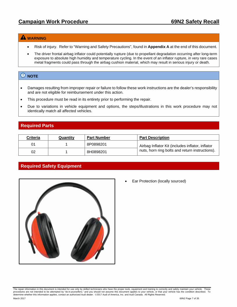
Install the new inflator onto the studs.
Ensure the recess on the inflator lines up properly with the tab on the airbag <arrow>.
Part Number Part Description
8P0898201 Inflator Kit – Criteria 01
8H0898201 Inflator Kit – Criteria 02
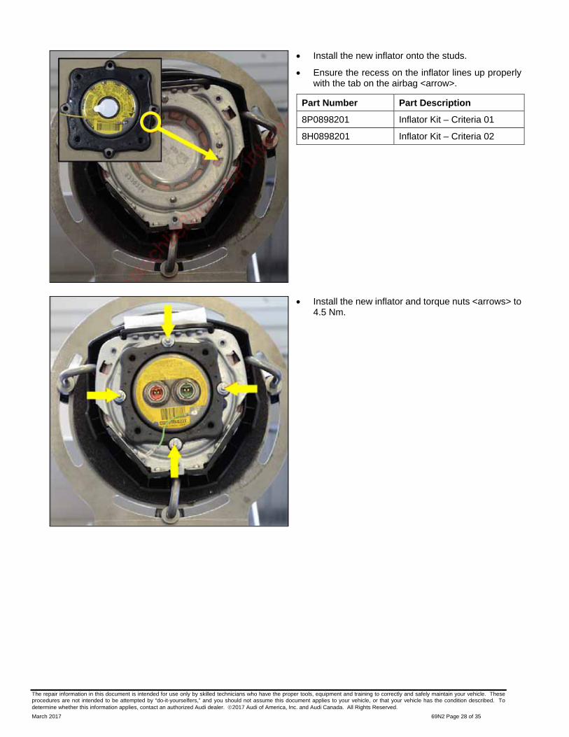
Install the new inflator and torque nuts <arrows> to 4.5 Nm.

The repair information in this document is intended for use only by skilled technicians who have the proper tools, equipment and training to correctly and safely maintain your vehicle. These procedures are not intended to be attempted by “do-it-yourselfers,” and you should not assume this document applies to your vehicle, or that your vehicle has the condition described. To determine whether this information applies, contact an authorized Audi dealer. 2017 Audi of America, Inc. and Audi Canada. All Rights Reserved.
March 2017 69N2 Page 29 of 35
Install the horn ring and tighten the bolts <arrows> to 6 Nm.
Install connectors <1, 2 and 3>.
NOTE
Ensure the connector locks are fully opened when installing the connectors.

The repair information in this document is intended for use only by skilled technicians who have the proper tools, equipment and training to correctly and safely maintain your vehicle. These procedures are not intended to be attempted by “do-it-yourselfers,” and you should not assume this document applies to your vehicle, or that your vehicle has the condition described. To determine whether this information applies, contact an authorized Audi dealer. 2017 Audi of America, Inc. and Audi Canada. All Rights Reserved.
March 2017 69N2 Page 30 of 35
Engage the connector locks <arrows>.
Ensure all wire connections are secure and the airbag harness is routed correctly.
Continue to Section F.
Section F – Airbag Installation
WARNING
The battery must be disconnected before installing the airbag back into the vehicle.
Before handling pyrotechnic components (for example, disconnecting the connector), the person handling it must “discharge static electricity”. This can be done by touching the door striker, for example.
Connect the spiral spring electrical connector <2> with the airbag connector coupling on the coil connector with slip ring.
Versions with Multi-function and Tiptronic steering wheel: Install the connector <3>.

The repair information in this document is intended for use only by skilled technicians who have the proper tools, equipment and training to correctly and safely maintain your vehicle. These procedures are not intended to be attempted by “do-it-yourselfers,” and you should not assume this document applies to your vehicle, or that your vehicle has the condition described. To determine whether this information applies, contact an authorized Audi dealer. 2017 Audi of America, Inc. and Audi Canada. All Rights Reserved.
March 2017 69N2 Page 31 of 35
Position the driver airbag in the steering wheel.
Install the 2 bolts -arrow- for securing the driver airbag approximately 2 turns.
Press horn about 3 times to achieve even gap dimension.
Torque the bolts <arrow> to 7 Nm.
Install the bolt cover caps.
Continue to Section G.
Section G – Battery Reconnect
A3 Procedure
Battery in Engine Compartment:
WARNING
Ignition must be ON when connecting battery. If pyrotechnic components (e.g. airbag, belt tensioner) are not repaired correctly, they may deploy unintentionally after connecting battery. There must not be anyone inside the vehicle when connecting the battery.
If equipped, disconnect the connector <3> from the Battery Monitoring Control Module -J367-.
Connect the battery ground cable terminal by hand to the battery negative terminal.
Torque the nut <1> to 6 Nm.
If equipped, reconnect the connector to the Battery Monitoring Control Module -J367-.
Install the battery terminal cover.
NOTE
After connecting the power supply, the ABS warning lamp may only go out after the vehicle has been driven a few yards.

The repair information in this document is intended for use only by skilled technicians who have the proper tools, equipment and training to correctly and safely maintain your vehicle. These procedures are not intended to be attempted by “do-it-yourselfers,” and you should not assume this document applies to your vehicle, or that your vehicle has the condition described. To determine whether this information applies, contact an authorized Audi dealer. 2017 Audi of America, Inc. and Audi Canada. All Rights Reserved.
March 2017 69N2 Page 32 of 35
Install battery cover <1>.
Store previously recorded radio presets.
Activate the power window regulator one-touch up/down function.
Check the DTC memories of all the control units and erase Under-voltage faults if necessary.
Repair is complete, proceed to Section H.
Battery in Luggage Compartment:
WARNING
Ignition must be ON when connecting battery. If pyrotechnic components (e.g. airbag, belt tensioner) are not repaired correctly, they may deploy unintentionally after connecting battery. There must not be anyone inside the vehicle when connecting the battery.
If equipped, disconnect the connector <2> from the Battery Monitoring Control Module -J367-.
Connect the battery ground cable terminal by hand to the battery negative terminal.
Torque the nut <1> to 6 Nm.
If equipped, reconnect the connector to the Battery Monitoring Control Module -J367-.
Install the molded insert on top of the battery.
Install the battery cover <arrow>.

The repair information in this document is intended for use only by skilled technicians who have the proper tools, equipment and training to correctly and safely maintain your vehicle. These procedures are not intended to be attempted by “do-it-yourselfers,” and you should not assume this document applies to your vehicle, or that your vehicle has the condition described. To determine whether this information applies, contact an authorized Audi dealer. 2017 Audi of America, Inc. and Audi Canada. All Rights Reserved.
March 2017 69N2 Page 33 of 35
Install the rear molded insert <3> which holds the vehicle tools.
Install the luggage compartment floor.
Cycle the ignition off and back on.
Store previously recorded radio presets (if necessary).
Set clock to local time.
Activate the power window regulator one-touch up/down function.
Check the DTC memories of all the control units and erase under-voltage faults if necessary.
Repair is complete, proceed to Section H.
A4 Cabriolet, RS4 Cabriolet and S4 Cabriolet Procedure:
WARNING
Ignition must be ON when connecting battery. If pyrotechnic components (e.g. airbag, belt tensioner) are not repaired correctly, they may deploy unintentionally after connecting battery. There must not be anyone inside the vehicle when connecting the battery.
Connect the battery ground cable terminal by hand to the battery negative terminal.
Torque the nut <arrow> to 7.5 Nm.
NOTE
After connecting the power supply, the ABS warning lamp may only go out after the vehicle has been driven a few yards.
Install battery cover.
Cycle the ignition off and back on.
Store previously recorded radio presets (if necessary).
Set clock to local time.
Activate the power window regulator one-touch up/down function.
Check the DTC memories of all the control units and erase under-voltage faults if necessary.
Proceed to Section H.

The repair information in this document is intended for use only by skilled technicians who have the proper tools, equipment and training to correctly and safely maintain your vehicle. These procedures are not intended to be attempted by “do-it-yourselfers,” and you should not assume this document applies to your vehicle, or that your vehicle has the condition described. To determine whether this information applies, contact an authorized Audi dealer. 2017 Audi of America, Inc. and Audi Canada. All Rights Reserved.
March 2017 69N2 Page 34 of 35
Section H – Campaign Completion Stamp
Item#: AUD4927ENG
-OR-
Item # AUD4927FRE
Once the campaign has been completed, the technician should stamp the repair order.
Stamps are available for ordering through the Compliance Label Ordering Portal.
Repair is Complete, Proceed to Appendix B (Mandatory Takata Inflator Return Process).

The repair information in this document is intended for use only by skilled technicians who have the proper tools, equipment and training to correctly and safely maintain your vehicle. These procedures are not intended to be attempted by “do-it-yourselfers,” and you should not assume this document applies to your vehicle, or that your vehicle has the condition described. To determine whether this information applies, contact an authorized Audi dealer. 2017 Audi of America, Inc. and Audi Canada. All Rights Reserved.
March 2017 69N2 Page 35 of 35
Appendix A – Warning and Safety Precautions
WARNING
General Safety Precautions when Working with Pyrotechnic Components:
Pyrotechnic components always contain propellant that generates a gas during combustion. In some components, there is also a supply of pressurized gas to ensure this gas is generated
This pressurized gas is stored under high pressure in a compressed gas container. Pyrotechnic components are triggered by electrical/mechanical igniters.
Only trained personnel should perform testing, assembly and servicing work. Airbags do not have a replacement interval.
Never check with test lamps, voltmeter or ohmmeters.
Only check pyrotechnic components when they are installed in the vehicle using vehicle diagnosis, testing and information systems approved by the manufacturer.
When working on pyrotechnic components and the airbag control module, disconnect the battery ground strap while the ignition is switched on. Then cover the negative terminal.
Wait 10 seconds after disconnecting the battery.
The ignition must be SWITCHED ON when connecting the battery. There should not be anyone inside the vehicle when doing this.
Exception: vehicles with batteries in the passenger compartment. In this case, stay outside the range of the airbags and seat belts.
Wash your hands after touching ignited pyrotechnic components from the restraint system.
Do not open or repair pyrotechnic components. Use only new components to reduce the risk of injury.
Do not install pyrotechnic components that have fallen onto a hard surface or show signs of damage.
Discharge static electricity before handling pyrotechnic components, for example before disconnecting the electrical connector. This can be done by touching grounded metal objects such as the door striker pin.
Install pyrotechnic components immediately after removing them from their transport packaging. If you must stop working, store the pyrotechnic component in its original transport packaging.
Do not leave pyrotechnic components lying in the open unattended.
Do not treat pyrotechnic components with grease, cleaning solutions or similar products.
Do not expose pyrotechnic components to temperatures above 100 ºC, even for brief periods of time.
Appendix B – Mandatory Inflator Return Process
Properly store (retain) removed parts in accordance with all state/province, local requirements.
Questions regarding the return process should be directed to the contacts listed on the included return instructions.
Additional instructions are located in the attachments in Elsa and ServiceNet.

5. Shipping Instructions – Prepare the Pallet a) Accumulate and palletize Kits b) Arrange Kits on Pallet as pictured here
• 20 boxes per row/layer (5x4) • 10 rows/layers per pallet (200 boxes)
c) Shrink-wrap Kits to Pallet d) Affix Over-pack Label on (1) side of Pallet (Not on Top)
NOTE
NOTE: International (including Mexico and Canada), Hawaii, Alaska, Puerto Rico, and US Virgin Islands dealers CANNOT follow below shipping instructions. Instead, dealerships in these locations MUST contact the following Takata/Menlo USA representative directly for shipping instructions: Miguel Prigadaa – Tel #: 210-250-5078 or Email: [email protected]. Or they can email the attached form to Menlo/XPO, (email is in the form) & they will make arrangements with Crane Worldwide to arrange pick up. As info, both emails go to the same international people that arrange the freight. [email protected]; [email protected] NOTE: For Continental US 48 State dealerships, please follow steps 1-8 below.
1. Shipping Documents
8. Requesting a New Box / Shipping Labels If a new box or replacement shipping labels are needed, please contact the representative listed below by phone or email to request replacement materials. Primary Contact: XPO Customer service Rep- Tel #: 210-250-5079 E-Mail: [email protected] To help expedite your request, please be prepared to provide the following information: a) Serial number on the original box b) What Type of shipping material needed • Replacement Box • Two Part Return Label • Bill of Lading • ERG Form c) Dealer Shipping Information • Contact name • Dealer Address • Phone Number
3. Closure Instructions a) Close the top box flap, per box closure instructions located on front panel of box.
2. Packing Instructions a) Confirm box is in acceptable condition. If a new box is needed, follow the New Box instructions located In Box 8 of this page. b) Place the un-deployed air bag inflator in the “cradle” of the box insert.
6. Shipping Instructions – Schedule LTL Pickup a) Upon Accumulating 200 kits (1 Over-pack/Pallet) Minimum • Call XPO at 1-888-708-5712 • If 200 Kits have not been accumulated in 30 days, please call XPO for
direction c) Have the following Information Available • Dealer # • Quantity of Over-packs/Pallets • Quantity of Passenger Inflator Kits on each Pallet • Email Address where shipping Documentation can be received
a) Box Label • Supplied with each Kit • To be affixed to each box b) Over-pack Label
• To be supplied by XPO
• To be affixed to the outside of each pallet
c) Bill of Lading • To be supplied by
XPO. • Print 2 copies: 1 for
Dealer Records, 1 for LTL Driver
d) ERG Document • To be supplied by
XPO. • To be provide by the
Dealer to the LTL Driver for each shipment
4. Shipping Instructions - Label each Box a) New Labels will begin shipping in each kit starting mid June, 2015
VW/Audi Inflator Kit will contain this two-
part label: Peel off ‘Ship To’
Label. Affix Label to Box.
Do not cover up Class 9 Marking.
7. Shipping Instructions – Ship a) Give 1 Copy of BOL and 1 Copy of ERG to Driver b) Retain 1 Copy of BOL for Dealership records and archive for 2 Years
U.S. Only

NOTECrane Worldwide Logistics will arrange pick‐up of all return Takata product. Dealers MUST follow directions on attached sign up form and pick‐up request instructions.
NOTE: For reference purposes only, see steps 1‐8 below.
1. Shipping Documents
a) Over‐pack Label • To be supplied
by carrier • To be affixed to the
outside of each pallet
b) Bill of Lading (BOL) • To be supplied
by carrier • Print 2 copies: 1 for
Dealer Records, 1 for truck Driver
c) ERG Document • To be supplied by carrier • To be provided by
the Dealer to the truck Driver for each shipment
4. Shipping Instructions ‐ Label each Box
a) This step is only necessary if label is included in box.
Affix Label to Box. Do not cover up Class 9 Marking.
Peel off ‘Ship To’ Label.
VW/Audi Inflator Kit will contain this two‐part label:
Canadian Dealers ‐ Do not contact XPO as noted on label
5. Shipping Instructions – Prepare the Pallet
Accumulate and palletize Kits Arrange Kits on Pallet as pictured here
20 boxes per row/layer (5x4) 10 rows/layers per pallet (200 boxes max)
Shrink‐wrap Kits to Pallet Affix Over‐pack Label on (1) side of Pallet (Not on Top)
e) Kits cannot be shipped in a master carton. If not enoughto palletize, kits can be returned in their individual Boxes with dangerous goods markings visible. Select "viasmall package" when shipping individually
8. Requesting a New Box / Shipping Labels If a new box or replacement shipping labels are needed, please email to
request replacement materials.
E‐Mail: [email protected]
To help expedite your request, provide the following information:
Serial number on the original box
What Type of shipping material needed
Replacement Box
Two Part Return Label ‐* if included
This picture may appear different on the box
c) Dealer Shipping Information
Contact name
Dealer Address
Phone Number
2. Packing Instructions
Confirm box is in acceptable condition.
Place the un‐deployed air bag inflator inthe “cradle” of the box insert.
6. Shipping Instructions – Schedule LTL Pickup
a) Upon Accumulating 200 kits (1 Over‐pack/Pallet) or 30 days since last shipment:
• Follow request instructions on pick‐up
b) Have the following Information Available • Dealer Number • Quantity of Over‐pack Pallets(200) or individual boxes • Quantity of Passenger Inflator Kits on each Over‐Pack Pallet • Email Address where shipping Documentation can be received
7. Shipping Instructions – Ship
a) Give 1 Copy of BOL and ERG to driver b) Retain 1 Copy of BOL for Dealership records and archive for 2 Years
3. Closure Instructions
a) Close the top box flap, per box closure instructions located on front panel of
CANADIAN DEALER DO NOT CONTACT XPO Do not ship with label inside the box Label on the box will vary as per country of origin Please file all tracking documents Contact your Campaign Specialist
If you have any issues, questions or require additional information regarding shipping, contact the following Takata/Menlo USA representative directly: Miguel Prigadaa Tel number: 210‐250‐5078 Email: [email protected]
Canadian Dealers ‐ Do Not Contact XPO Doreen Daigle, Campaign Specialist Tel number: (905) 428‐4601 E‐mail:


![Bday [repaired]](https://static.fdocuments.us/doc/165x107/546ccabbaf7959ec228b4e34/bday-repaired.jpg)