SAFETY MANUAL SIL Relay Module - Pepperl+Fuchs
20
ISO9001 2 3 Relay Module KFD0-RO-(Ex)* PROCESS AUTOMATION SAFETY MANUAL SIL
Transcript of SAFETY MANUAL SIL Relay Module - Pepperl+Fuchs
ISO9001
23
Relay ModuleKFD0-RO-(Ex)*
PROCESS AUTOMATION
SAFETY MANUAL SIL
With regard to the supply of products, the current issue of the following document is applicable: The General Terms of Delivery for Products and Services of the Electrical Industry, published by the
Central Association of the Electrical Industry (Zentralverband Elektrotechnik und Elektroindustrie (ZVEI) e.V.) in its most recent version as well as the supplementary clause: "Expanded reservation
of proprietorship"
Safety Manual SIL KFD0-RO-(Ex)*
Safety Manual SIL KFD0-RO-(Ex)*Contents
2012
-07
3
1 Introduction......................................................................... 41.1 General Information.......................................................................................41.2 Intended Use ................................................................................................51.3 Manufacturer Information ..............................................................................51.4 Relevant Standards and Directives ...............................................................5
2 Planning .............................................................................. 62.1 System Structure...........................................................................................6
2.1.1 Low Demand Mode ..................................................................................62.1.2 High Demand Mode .................................................................................62.1.3 Safe Failure Fraction.................................................................................6
2.2 Assumptions .................................................................................................72.3 Safety Function and Safe State .....................................................................82.4 Characteristic Safety Values .........................................................................9
3 Safety Recommendation.................................................. 103.1 Interfaces ....................................................................................................103.2 Configuration ..............................................................................................103.3 Useful Life Time ..........................................................................................113.4 Installation and Commissioning ..................................................................13
4 Proof Test .......................................................................... 144.1 Proof Test Procedure ..................................................................................14
5 Abbreviations.................................................................... 16
2012
-07
4
Safety Manual SIL KFD0-RO-(Ex)*Introduction
1 Introduction1.1 General Information
This manual contains information for application of the device in functional safety related loops.The corresponding data sheets, the operating instructions, the system description, the Declaration of Conformity, the EC-Type-Examination Certificate and applicable Certificates (see data sheet) are integral parts of this document.The documents mentioned are available from www.pepperl-fuchs.com or by contacting your local Pepperl+Fuchs representative.Mounting, installation, commissioning, operation, maintenance and disassembly of any devices may only be carried out by trained, qualified personnel. The instruction manual must be read and understood.When it is not possible to correct faults, the devices must be taken out of service and action taken to protect against accidental use. Devices should only be repaired directly by the manufacturer. De-activating or bypassing safety functions or failure to follow the advice given in this manual (causing disturbances or impairment of safety functions) may cause damage to property, environment or persons for which Pepperl+Fuchs GmbH will not be liable. The devices are developed, manufactured and tested according to the relevant safety standards. They must only be used for the applications described in the instructions and with specified environmental conditions, and only in connection with approved external devices.
Safety Manual SIL KFD0-RO-(Ex)*Introduction
2012
-07
5
1.2 Intended UseKFD0-RO-*The KFD0-RO-* provides the galvanic isolation between field circuits and control circuits. The device switches circuits on the field side.KFD0-RO-Ex*The KFD0-RO-Ex* is used for intrinsic safety applications. The device switches intrinsically safe circuits on the field side.GeneralTypical applications for the use of the device are remote reset, fire alarm testing or remote calibration of strain gauges.The outputs are galvanically isolated to the inputs. The inputs are not polarized and share a common reference potential.Each input of the device is protected by a fuse and an electronic current limiting.The KFD0-RO-(Ex)* is a single device for DIN rail mounting.
1.3 Manufacturer InformationPepperl+Fuchs GmbHLilienthalstrasse 200, 68307 Mannheim, Germany
Up to SIL3
1.4 Relevant Standards and DirectivesDevice specific standards and directives Functional safety IEC 61508 part 2, edition 2000:
Standard of functional safety of electrical/electronic/programmable electronic safety-related systems (product manufacturer)
Electromagnetic compatibility:- EN 61326-1:2006- NE 21:2006
System specific standards and directives Functional safety IEC 61511 part 1, edition 2003:
Standard of functional safety: safety instrumented systems for the process industry sector (user)
KFD0-RO-*KFD0-RO-Ex*
2012
-07
6
Safety Manual SIL KFD0-RO-(Ex)*Planning
2 Planning2.1 System Structure2.1.1 Low Demand Mode
If there are two loops, one for the standard operation and another one for the functional safety, then usually the demand rate for the safety loop is assumed to be less than once per year.The relevant safety parameters to be verified are: the PFDavg value (average Probability of Failure on Demand) and
Tproof (proof test interval that has a direct impact on the PFDavg) the SFF value (Safe Failure Fraction) the HFT architecture (Hardware Fault Tolerance architecture)
2.1.2 High Demand ModeIf there is only one loop, which combines the standard operation and safety related operation, then usually the demand rate for this loop is assumed to be higher than once per year.The relevant safety parameters to be verified are: PFH (Probability of dangerous Failure per Hour) Fault reaction time of the safety system the SFF value (Safe Failure Fraction) the HFT architecture (Hardware Fault Tolerance architecture)
2.1.3 Safe Failure FractionThe safe failure fraction describes the ratio of all safe failures and dangerous detected failures to the total failure rate.SFF = (λs + λdd) / (λs + λdd + λdu)A safe failure fraction as defined in EN 61508 is only relevant for elements or (sub)systems in a complete safety loop. The device under consideration is always part of a safety loop but is not regarded as a complete element or subsystem.For calculating the SIL of a safety loop it is necessary to evaluate the safe failure fraction of elements, subsystems and the complete system, but not of a single device.Nevertheless the SFF of the device is given in this document for reference.
Safety Manual SIL KFD0-RO-(Ex)*Planning
2012
-07
7
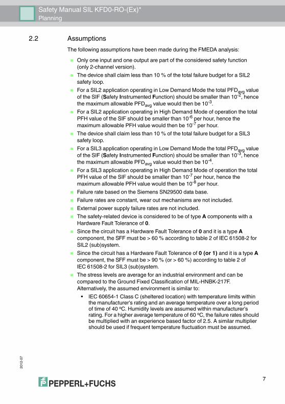
2.2 AssumptionsThe following assumptions have been made during the FMEDA analysis: Only one input and one output are part of the considered safety function
(only 2-channel version). The device shall claim less than 10 % of the total failure budget for a SIL2
safety loop. For a SIL2 application operating in Low Demand Mode the total PFDavg value
of the SIF (Safety Instrumented Function) should be smaller than 10-2, hence the maximum allowable PFDavg value would then be 10-3.
For a SIL2 application operating in High Demand Mode of operation the total PFH value of the SIF should be smaller than 10-6 per hour, hence the maximum allowable PFH value would then be 10-7 per hour.
The device shall claim less than 10 % of the total failure budget for a SIL3 safety loop.
For a SIL3 application operating in Low Demand Mode the total PFDavg value of the SIF (Safety Instrumented Function) should be smaller than 10-3, hence the maximum allowable PFDavg value would then be 10-4.
For a SIL3 application operating in High Demand Mode of operation the total PFH value of the SIF should be smaller than 10-7 per hour, hence the maximum allowable PFH value would then be 10-8 per hour.
Failure rate based on the Siemens SN29500 data base. Failure rates are constant, wear out mechanisms are not included. External power supply failure rates are not included. The safety-related device is considered to be of type A components with a
Hardware Fault Tolerance of 0. Since the circuit has a Hardware Fault Tolerance of 0 and it is a type A
component, the SFF must be > 60 % according to table 2 of IEC 61508-2 for SIL2 (sub)system.
Since the circuit has a Hardware Fault Tolerance of 0 (or 1) and it is a type A component, the SFF must be > 90 % (or > 60 %) according to table 2 of IEC 61508-2 for SIL3 (sub)system.
The stress levels are average for an industrial environment and can be compared to the Ground Fixed Classification of MIL-HNBK-217F. Alternatively, the assumed environment is similar to:
• IEC 60654-1 Class C (sheltered location) with temperature limits within the manufacturer's rating and an average temperature over a long period of time of 40 ºC. Humidity levels are assumed within manufacturer's rating. For a higher average temperature of 60 ºC, the failure rates should be multiplied with an experience based factor of 2.5. A similar multiplier should be used if frequent temperature fluctuation must be assumed.
2012
-07
8
Safety Manual SIL KFD0-RO-(Ex)*Planning
It was assumed that the appearance of a safe error (e. g. output in safe state) would be repaired within 8 hours (e. g. remove sensor burnout).
During the absence of the device for repairing, measures have to be taken to ensure the safety function (for example: substitution by an equivalent device).
For the calculation it was also assumed that the indication of a dangerous error (via fault bus) would be detected within 1 hour by the logic solver (SPS).
2.3 Safety Function and Safe StateThe safety function is that a de-energized input leads to the output being open (not conducting). The output at pins 2 and 3 (pins 5 and 6 for channel 2) in open circuit is the safe state.Reaction TimeThe reaction time for all safety functions is < 20 ms.
Safety Manual SIL KFD0-RO-(Ex)*Planning
2012
-07
9
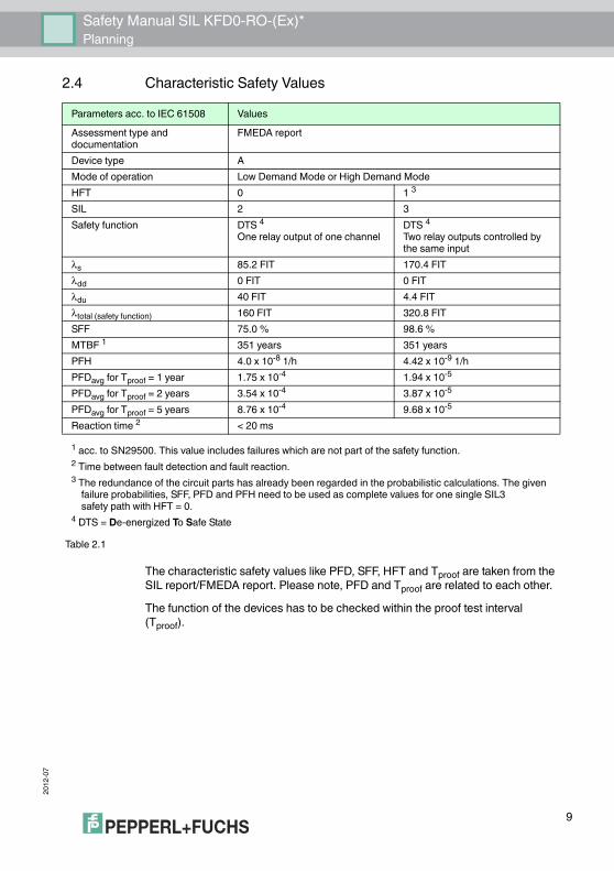
2.4 Characteristic Safety Values
The characteristic safety values like PFD, SFF, HFT and Tproof are taken from the SIL report/FMEDA report. Please note, PFD and Tproof are related to each other.The function of the devices has to be checked within the proof test interval (Tproof).
Parameters acc. to IEC 61508 ValuesAssessment type and documentation
FMEDA report
Device type AMode of operation Low Demand Mode or High Demand ModeHFT 0 1 3SIL 2 3Safety function DTS 4
One relay output of one channelDTS 4Two relay outputs controlled by the same input
λs 85.2 FIT 170.4 FITλdd 0 FIT 0 FITλdu 40 FIT 4.4 FITλtotal (safety function) 160 FIT 320.8 FITSFF 75.0 % 98.6 %MTBF 1 351 years 351 yearsPFH 4.0 x 10⁻⁸ 1/h 4.42 x 10⁻⁹ 1/hPFDavg for Tproof = 1 year 1.75 x 10⁻⁴ 1.94 x 10⁻⁵
PFDavg for Tproof = 2 years 3.54 x 10⁻⁴ 3.87 x 10⁻⁵
PFDavg for Tproof = 5 years 8.76 x 10⁻⁴ 9.68 x 10⁻⁵
Reaction time 2 < 20 ms1 acc. to SN29500. This value includes failures which are not part of the safety function.2 Time between fault detection and fault reaction.3 The redundance of the circuit parts has already been regarded in the probabilistic calculations. The given failure probabilities, SFF, PFD and PFH need to be used as complete values for one single SIL3 safety path with HFT = 0.4 DTS = De-energized To Safe State
Table 2.1
2012
-07
10
Safety Manual SIL KFD0-RO-(Ex)*Safety Recommendation
3 Safety Recommendation3.1 Interfaces
The device has the following interfaces. For corresponding terminals see data sheet. Safety relevant interfaces: input I, input II, output I, output II
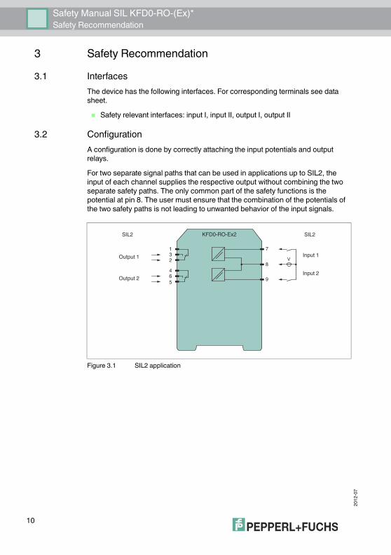
3.2 ConfigurationA configuration is done by correctly attaching the input potentials and output relays.For two separate signal paths that can be used in applications up to SIL2, the input of each channel supplies the respective output without combining the two separate safety paths. The only common part of the safety functions is the potential at pin 8. The user must ensure that the combination of the potentials of the two safety paths is not leading to unwanted behavior of the input signals.
Figure 3.1 SIL2 application
KFD0-RO-Ex2
231
564
7
8
9
VOutput 1
Output 2
Input 1
Input 2
SIL2SIL2
Safety Manual SIL KFD0-RO-(Ex)*Safety Recommendation
2012
-07
11
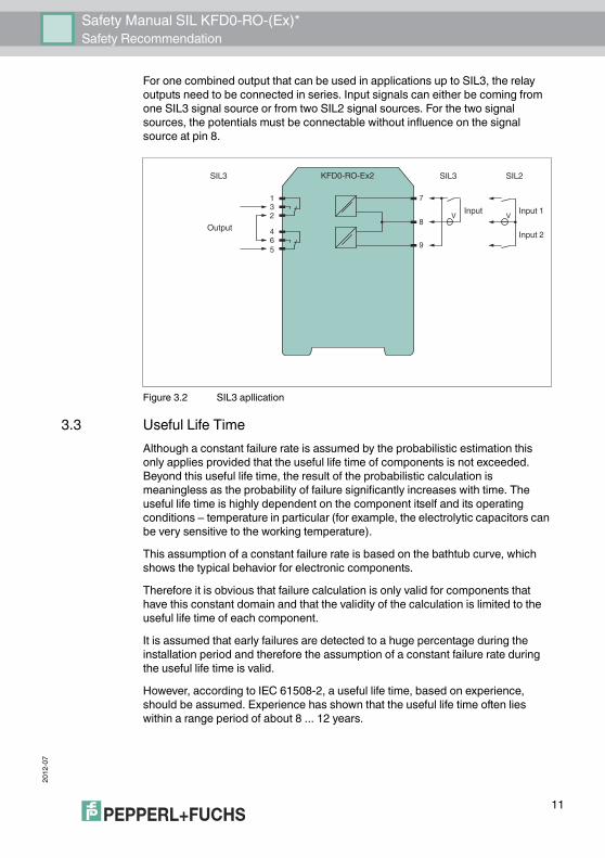
For one combined output that can be used in applications up to SIL3, the relay outputs need to be connected in series. Input signals can either be coming from one SIL3 signal source or from two SIL2 signal sources. For the two signal sources, the potentials must be connectable without influence on the signal source at pin 8.
Figure 3.2 SIL3 apllication
3.3 Useful Life TimeAlthough a constant failure rate is assumed by the probabilistic estimation this only applies provided that the useful life time of components is not exceeded. Beyond this useful life time, the result of the probabilistic calculation is meaningless as the probability of failure significantly increases with time. The useful life time is highly dependent on the component itself and its operating conditions – temperature in particular (for example, the electrolytic capacitors can be very sensitive to the working temperature).This assumption of a constant failure rate is based on the bathtub curve, which shows the typical behavior for electronic components.Therefore it is obvious that failure calculation is only valid for components that have this constant domain and that the validity of the calculation is limited to the useful life time of each component.It is assumed that early failures are detected to a huge percentage during the installation period and therefore the assumption of a constant failure rate during the useful life time is valid.However, according to IEC 61508-2, a useful life time, based on experience, should be assumed. Experience has shown that the useful life time often lies within a range period of about 8 ... 12 years.
KFD0-RO-Ex2
231
564
7
8
9Output
SIL3SIL3 SIL2
Input 1
Input 2
VV Input
2012
-07
12
Safety Manual SIL KFD0-RO-(Ex)*Safety Recommendation
Our experience has shown that the useful life time of a Pepperl+Fuchs product can be higher if there are no components with reduced life time in the safety path (like
electrolytic capacitors, relays, flash memory, opto coupler) which can produce dangerous undetected failures and
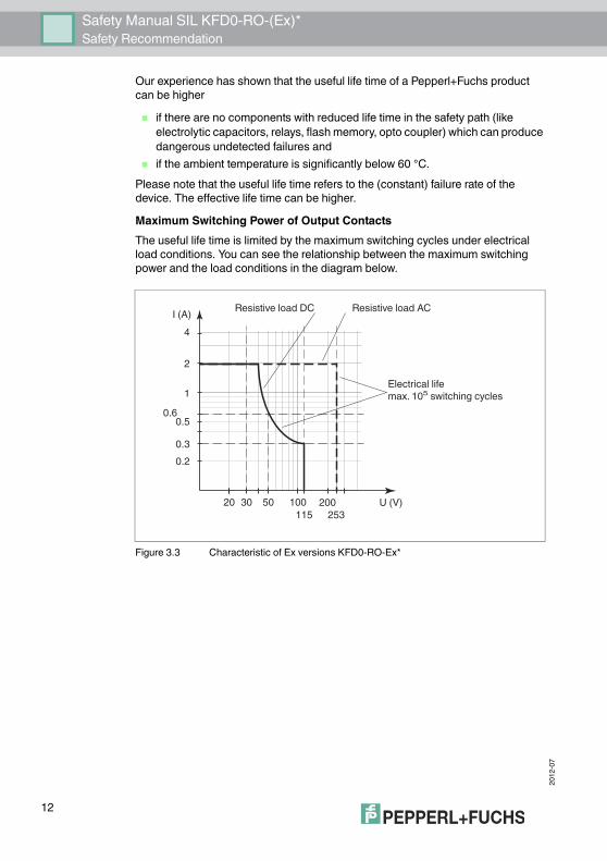
if the ambient temperature is significantly below 60 °C.Please note that the useful life time refers to the (constant) failure rate of the device. The effective life time can be higher.Maximum Switching Power of Output ContactsThe useful life time is limited by the maximum switching cycles under electrical load conditions. You can see the relationship between the maximum switching power and the load conditions in the diagram below.
Figure 3.3 Characteristic of Ex versions KFD0-RO-Ex*
1
I (A)
2
4
10030 50 200115 253
U (V)20
0.50.6
0.20.3
Resistive load ACResistive load DC
Electrical lifemax. 105 switching cycles
Safety Manual SIL KFD0-RO-(Ex)*Safety Recommendation
2012
-07
13
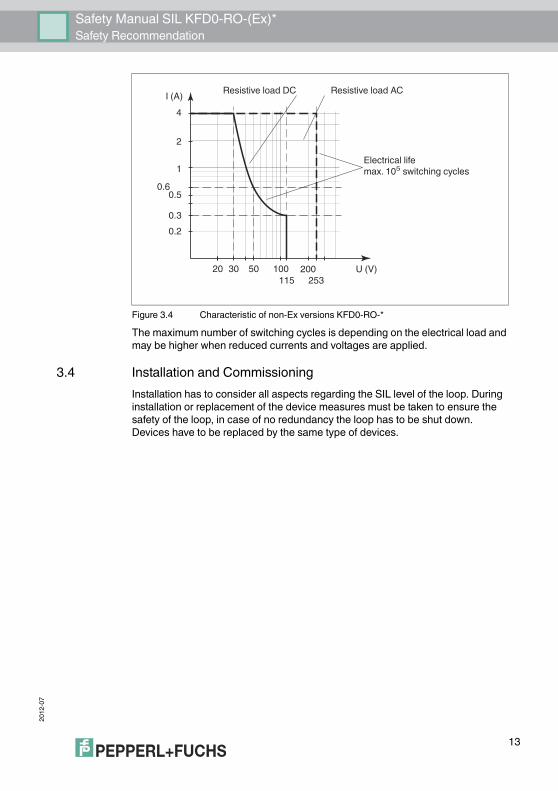
Figure 3.4 Characteristic of non-Ex versions KFD0-RO-*The maximum number of switching cycles is depending on the electrical load and may be higher when reduced currents and voltages are applied.
3.4 Installation and CommissioningInstallation has to consider all aspects regarding the SIL level of the loop. During installation or replacement of the device measures must be taken to ensure the safety of the loop, in case of no redundancy the loop has to be shut down. Devices have to be replaced by the same type of devices.
1
I (A)
2
4
10030 50 200115 253
U (V)20
0.50.6
0.20.3
Resistive load ACResistive load DC
Electrical lifemax. 105 switching cycles
2012
-07
14
Safety Manual SIL KFD0-RO-(Ex)*Proof Test
4 Proof Test4.1 Proof Test Procedure
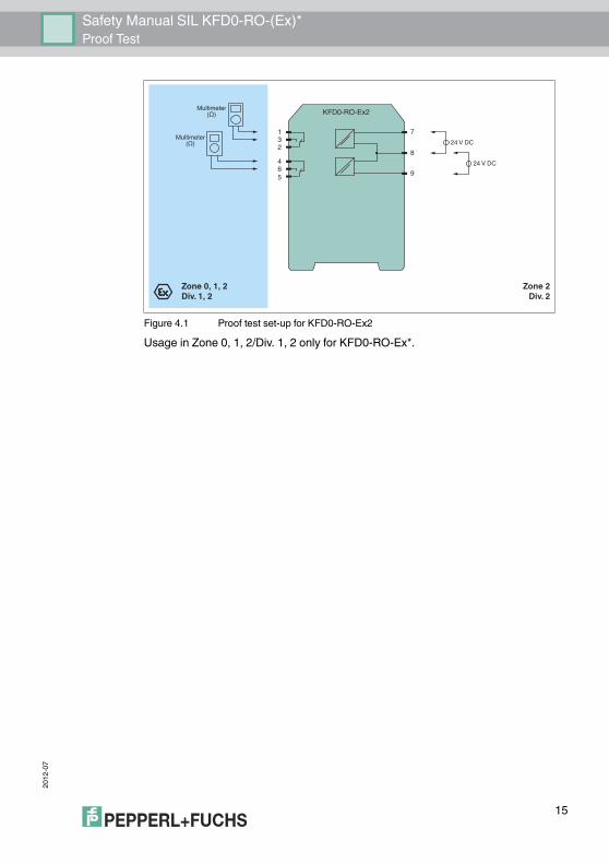
According to IEC 61508-2 a recurring proof test shall be undertaken to reveal potential dangerous failures that are otherwise not detected by diagnostic test.The functionality of the subsystem must be verified at periodic intervals depending on the applied PFDavg in accordance with the data provided in this manual. see chapter 2.4.It is under the responsibility of the operator to define the type of proof test and the interval time period.The ancillary equipment required: Digital multimeter with an accuracy better than 0.1 %
For the proof test of the intrinsic safety side of the devices, a special digital multimeter for intrinsic safety circuits must be used. Intrinsic safety circuits that were operated with circuits of other types of protection may not be used as intrinsically safe circuits afterwards.
Power supply set at nominal voltage of 24 V DCThe settings have to be verified after the configuration by means of suitable tests.Procedure:The voltage input must be simulated by applying a 24 V supply in the orientation that is used for this safety application. Where both polarities are used the test must be done in both orientations.The input test needs to be done for each input channel individually. Without voltage applied between terminals 7 and 8(second channel
terminals 8 and 9), terminals 1 and 2 (second channel terminals 4 and 5) must be conducting while terminals 2 and 3 (second channel terminals 5 and 6) must be non-conducting. The corresponding LED must be off.
When voltage is applied between terminals 7 and 8 (second channel terminals 8 and 9), the state of the outputs is exactly the opposite to the situation without voltage applied.
Safety Manual SIL KFD0-RO-(Ex)*Proof Test
2012
-07
15
Figure 4.1 Proof test set-up for KFD0-RO-Ex2Usage in Zone 0, 1, 2/Div. 1, 2 only for KFD0-RO-Ex*.
Zone 0, 1, 2Div. 1, 2
Zone 2Div. 2
Multimeter(Ω)
Multimeter(Ω) 24 V DC
KFD0-RO-Ex2
231
564
7
8
924 V DC
2012
-07
16
Safety Manual SIL KFD0-RO-(Ex)*Abbreviations
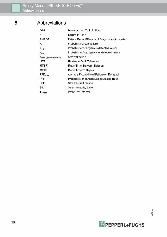
5 AbbreviationsDTS De-energized To Safe StateFIT Failure In TimeFMEDA Failure Mode, Effects and Diagnostics Analysisλs Probability of safe failureλdd Probability of dangerous detected failureλdu Probability of dangerous undetected failureλtotal (safety function) Safety functionHFT Hardware Fault ToleranceMTBF Mean Time Between FailuresMTTR Mean Time To RepairPFDavg Average Probability of Failure on DemandPFH Probability of dangerous Failure per HourSFF Safe Failure FractionSIL Safety Integrity LevelTproof Proof Test Interval

Safety Manual SIL KFD0-RO-(Ex)*Notes
2012
-07
17
2012
-07
18
Safety Manual SIL KFD0-RO-(Ex)*Notes
Safety Manual SIL KFD0-RO-(Ex)*Notes
2012
-07
19

Subject to modificationsCopyright PEPPERL+FUCHS • Printed in Germany
www.pepperl-fuchs.com
Worldwide HeadquartersPepperl+Fuchs GmbH68307 Mannheim · GermanyTel. +49 621 776-0E-mail: [email protected]
For the Pepperl+Fuchs representative closest to you check www.pepperl-fuchs.com/contact
PROCESS AUTOMATION – PROTECTING YOUR PROCESS
TDOCT-2763_ENG07/2012