THE PULSE OF AUTOMATION - Pepperl+Fuchs
72
TECHNOLOGY GUIDE ULTRASONICS BY PEPPERL+FUCHS THE PULSE OF AUTOMATION
Transcript of THE PULSE OF AUTOMATION - Pepperl+Fuchs

TECHNOLOGY GUIDE ULTRASONICS BY PEPPERL+FUCHS
THE PULSE OF AUTOMATION


TECHNOLOGY GUIDE ULTRASONICS

2
A willingness to take entrepreneurial risks, a pioneering spirit, and a firm belief in their own inventive powers – these were the assets that Walter Pepperl and Ludwig Fuchs started out with when they opened their Mannheim radio repair shop in 1945. Their invention of the proximity switch a few years later proved their strength. It was also the starting point in a successful history defined by close customer relationships as well as innovative automation technologies and procedures.
Automation is our world. A perfect application solution is our goal.
Then as now, our focus is squarely on the individual requirements of each customer. Whether as a pioneer in electrical explosion protection, or as a leading innovator of highly efficient sensors – the intensive communication with our customers is what allowed us to become the leader in automation technology. Our main objective is combining state-of-the-art technologies and comprehensive services to optimize our customers’ processes and applications.
For more information, please visit our website: www.pepperl-fuchs.com

3
ContentAutomation is our world. A perfect application solution is our goal.
1. Principles
1.1. Function 6
1.2. Sound Beam and Response Curve 14
1.3. Operating Modes 18
1.4. Switching Outputs 24
1.5. Analog Output 28
1.6.InfluencingFactors 30
1.7. Installation and Assembly 34
1.8. Synchronization and Multiplex Modes 38
2. Applications
2.1. Level Measurement 42 2.2. Mobile Equipment 48 2.3. Material Handling 56
2.4. Food and Beverage 60
2.5. Doors, Gates, and Elevators 62

4
Sensor Technology with a Finger on the Pulse of Automation
Nature shows us how precisely sonar systems work: even the most sophisticated camouflage cannot help a moth if it is in the range of a batʼs natural sonar. Dolphins use the same principle to find their prey in murky water. Both of these animals obtain their basic means of subsistence by detecting and evaluating the echo of sonic waves. Their sensors work reliably, even under the most challenging conditions.
In industrial applications, ultrasonic sensors are characterized by their reliability and, in particular, by their tremendous versatility. They can be used to solve even the most complex of tasks involving the detection of objects or levels, because their measuring method works reliably under almost all conditions. Ultrasonic sensor technology is relatively new. By the time it was introduced to the industry, optical and inductive methods had already been established for many years.
But over the past 30 years, ultrasonic technology has caught up and proven its suitability for everyday use in impressive fashion. Pepperl+Fuchs and Siemens played an important role in this development. Since we took over Siemens’ proximity switch division in 2010, we have been able to draw on more than 30 years of experience shared by both companies in this area.

5
All measuring methods are pushed to their physical limits in certain applications. Ultrasound first came into use when reliable sensors were sought for applications for which existing methods were not suitable. The new principle expanded the range of metrological options, but for a long time was seen only as a solution for particularly tricky scenarios and was even considered to be a rather complex form of technology.
These times have long since passed – even if everyone is not yet aware of this.
As the global market and technology leader for ultrasonic sensors in the industry, we are able to offer the largest portfolio of standard products in this area, featuring optimal solutions for most applications. If this is not enough, we also have the expertise and infrastructure to quickly and flexibly respond to our customersʼ requirements: we develop and manufacture our ultrasonic transducers in our own technology center and have a dedicated department of first-class experts on hand for application-specific development work. Our slogan, “The pulse of automation – Ultrasonics by Pepperl+Fuchs”, describes the area where we excel and defines our aspiration to always be the best in this field.
Wolfgang Helm Director Business Unit Sensors Pepperl+Fuchs GmbH
Ultrasonic sensors have successfully passed practical endurance tests in virtually all industrial sectors and are also being used in Industry 4.0 applications. No other measuring method can be successfully put to use on such a wide scale and in so many different applications. The devices are extremely robust, making them suitable for even the toughest conditions. The sensor surface cleans itself through vibration, but that is not the only reason why the sensor is insensitive to dirt. The physical principle – the propagation of sound – works, with a few exceptions, in practically any environment, no matter how dusty or dirty.

6
Ultrasound for Superior Performance
1. Principles | 1.1. Function
Structure of an ultrasonic sensor.
Ultrasonic sensors precisely detect objects made from various materials regardless of their shape, color, or surface contour. They operate using high-frequency sound waves that are inaudible to the human ear.
1.1.1. Physical Principles
Sound waves with a frequency above approximately 16 kHz are referred to as ultrasonic. These sound waves can travel through a wide variety of media and effectively detect or monitor objects with a relatively high density. Common ultrasonic targets include solids, liquids, and granular materials. Sound waves cannot travel in a vacuum.
Because the transmission properties and speed of sound change in different media, sensors must be adapted specifically to each medium. Pepperl+Fuchsʼ ultrasonic sensors are optimized for the propagation of sound waves in the air. The ultrasonic transducer operates freely in the air and cannot be used underwater.
Ultrasonic transducers work at different frequencies in the range of 60 kHz to 850 kHz. As the ultrasonic frequency increases, so does the attenuation of the sound waves in the air. Therefore, long-range sensors work at low frequencies, and short-range sensors work at high frequencies.

7
Pepperl+Fuchs’ ultrasonic sensors use piezoceramics to produce ultrasonic waves. A piezoceramic is connected to two electrodes. It is electrically actuated with the corresponding frequency and then operates as an emitter for emitting sound waves into the air. When the sound waves are reflected back from an object, the transducer serves as a receiver and converts the sound waves back into an electrical signal. Basically, it converts the electrical energy to acoustic energy, (transmit mode) and then converts the returned acoustic energy back to electrical energy (receive mode).
A patented decoupling layer is glued to the piezoelectric transducer with epoxy resin to couple and decouple the ultrasonic waves to the surrounding air.
An additional metal ring is installed to achieve the tightest possible sound propagation. The piezoceramic, decoupling layer, and metal ring are assembled into a housing. The watertight assembly is then embedded in polyurethane foam (PUR) to ensure an unrestricted vibration.
This basic design was developed and patented over three decades ago and has been continually improved by Pepperl+Fuchs.
For example, conventional transducers produce a main beam and what are known as side lobes. This creates a beam with a relatively large diameter. Where installation space is limited, the large diameter and side lobes can be a problem.
Working to improve transducer technology, Pepperl+Fuchs has had a significant influence on the shape and range of the ultrasonic beam. Years of research have resulted in long-range sound beams with almost no side lobes.
The most recent generation of Pepperl+Fuchs sensors includes transducers just 18 mm in diameter with ranges of over 2 m, and 30 mm diameter transducers with 4 m ranges.
Special transducer models and sensors in stainless-steel housings are available for applications with aggressive materials, such as chemicals, acids, or alkalis. In these models, the entire transducer (piezo, decoupling layer, foam) is coated with a chemically resistant film (PTFE, FEP) that protects the assembly from the aggres-sive media.
The transducers are sealed in a stainless-steel housing. This not only enables them to be used in aggressive environments, but also fulfills conventional hygiene requirements for the food industry.

8
1. Principles | 1.1. Function
The ultrasonic sensor measures the time difference between the emitted pulse and received echo.
1.1.2. Ultrasonic Principle
Ultrasonic sensors are able to detect an object without making physical contact and determine its distance from the sensor. Depending on the type of sensor, these distances can range from a few centimeters up to ten meters. The sensor emits ultrasonic pulses that are then reflected by an object. The generated echo is received again by the sensor and converted into an electric signal via the piezoelectric transducer. This is known as the propagation time of sound.
The sensor measures the time lag between the emitted ultrasonic pulse and the received echo and calculates the distance to the object using the speed of sound. At room temperature, the speed of sound in air is about 344 m/s.
Pepperl+Fuchsʼ ultrasonic sensors detect objects made from different materials, such as wood, metal, or plastic, regardless of their shape or color, and these objects can be solid, liquid, or in powder form. The only requirement is that they are able to reflect sound waves back to the sensor.
Some objects, however, could reduce the operating range. These include objects with a large, smooth, and slanted surface or porous targets such as felt, wool, or foam rubber.
The sensing range of an ultrasonic sensor depends on the surface properties and angle of the object. The longest sensing ranges are achieved with objects that have a flat surface (standard reflector) positioned at an exact right angle to the sensor axis.
Very small objects or objects that partially deflect the sound will reduce the sensing range. Objects with smooth surfaces must be positioned as close as possible to an angle of 90°. Rough surfaces can tolerate much larger angular deviations.
Environmental effects must also be considered. The biggest influence on the accuracy of an ultrasonic sensor is the air temperature. Pepperl+Fuchsʼ ultrasonic sensors are equipped with compensation circuitry to eliminate temperature effects on the sensor output. Relative humidity and barometric pressure must also be considered.

9
1. Grundlagen | 1.1 Funktionsweise
Ultrasonic sensors detect a wide variety of materials and are not affected by problematic surfaces.

10
1. Principles | 1.1. Function
Blind zone
Sensing range
Object
Switching or analog area (LED illuminates)
1.1.3. Evaluation of Measurement Results
Ultrasonics have transducers that alternately emit sound and wait for the sound waves reflected from the object. But because the transducer continues vibrating after emitting a pulse, the echoes cannot be received immediately. This delay corresponds to a blind zone. This blind zone is located directly in front of the sensor, and the target cannot be reliably detected. No objects should be placed in this area. Note, however, that sensors with separate emitter and receiver transducers (thru-beam sensors) have no blind zone.
The sensing range is the area beyond the blind zone where the detection of objects is possible. It is defined by the shortest and longest distance. Ultrasonic sensors can evaluate the distance to an object or a liquid surface within the sensing range using a variety of methods:
n The distance can be converted to an analog value and issued via industry-standard analog outputs: 0–10 V, 4–20 mA. An arbitrary measuring window can be set within the near and far evaluation limits of the sensor. The relative data determines the position of the object in the measuring window.
n The distance can be transmitted directly to a controller (PLC) as a digital value, e.g. via IO-Link.
n The distance can be internally compared with the configured switching limits. If an object is located in the switching area, this is indicated at a binary switching output, such as PNP or NPN.

11
1.1.4. Adjustment within the Sensing Range
Within the sensing range, it is possible to define distance limits or windows (switching range, analog range) using a Teach-In function, a potentiometer, or programming software.
Teach-In
Teach-In ultrasonic sensors allow users to define various parameters, such as range, a switching limit, or analog limit. Several functions and operating concepts are available, depending on the sensor type and design.
n Sensors with small housings usually have a function input. Connecting the input to supply voltage L+ or L– configures the desired Teach-In value and saves it permanently in the sensor. The function input can be connected manually or with a Teach-In adapter. The function input is connected to the supply voltage using a switch.
n Cube-style and larger cylindrical housings (M30) often feature controls such as buttons or programming plugs, which can be used to trigger the Teach-In process directly. Using programming software, different functions such as switching limits (NO contact/NC contact) or analog limits, sound beam properties, and analog characteristics can be changed on the different Teach-In levels. Differently colored LEDs and different flashing frequencies confirm correct Teach-In processes, report error messages, or signal the current Teach-In level.
Potentiometer
Potentiometers attached directly to the device are another option for adjusting switching or analog limits. Potentiometers have only one function: they adjust a single limit (beginning or end) of the switching range or analog range.
Status LEDs indicate the presence of an object in the switching or analog range, or signal a faulty adjustment.
L1
L2
L1
T1 T2 L2
LED yellow LED yellow
LED green/red
Setting the switching or analog limits using a button.
Potentiometer 2
Potentiometer 1
LED 2yellow/green
LED 1yellow
Temperature probe
Device connector
Setting the switching or analog limits using a potentiometer.

12
1. Principles | 1.1. Function
Programming Software
The easiest way to adjust the sensor is using programming software.
Pepperl+Fuchs ’ ultrasonic sensors can be programmed using the ULTRA3000, SONPROG, PACTware (IO-Link), or ULTRA-PROG-IR. These programs provide instant communication between the sensor and the computer. Rather than manually typing in each command or parameter, adjustments are made with a simple mouse click.
You can easily set the sensor parameters, display the commands sent to and received by the sensor, and display the most recently measured distance. In addition, you have precise control of features not found in ordinary sensors, including:
n Sensing range and boundaries
n Extended sensing ranges
n Blind zone (telling the sensor to ignore objects within a certain range directly in front of itself )
n Sensitivity (beam width)
n Number of pulses evaluated per output
n Hysteresis
n Sound burst times
n Temperature offset
n Output mode
Pros and Cons of Different Operating Concepts
During the Teach-In process, an object is positioned in the sensing range and its position is recorded with millimeter precision. This product can also be used as the reference object.
Teach-In processes are usually performed via a function input when the system or machine is being commissioned.
This requires manual wiring or a Teach-In adapter. During operation, Teach-In values can be changed only with manual intervention in the wiring (tamper-resistant).
For devices with Teach-In push buttons, the values can be changed easily even after the system has been installed and commissioned. For example, switching limits or analog limits can be adjusted when process control levels are changed. Many Pepperl+Fuchs sensors provide Teach-In locking to prevent the Teach-In values from being accidently changed.
Setting the switching limits or analog limits via a potentiometer eliminates the need to modify the wiring. In addition, the set limit value can be visually recognized from the potentiometer position.
However, it is difficult to adjust devices with potentiometers with millimeter precision.
Setting the sensor using programming software combines the advantages of Teach-In and potentiometer operating concepts. Switching limits or analog limits can be set with or without a reference object. The set values are seen on the screen and are easily adjusted with millimeter precision. The programming software also provides the option of changing many other sensor parameters (sound beam modification, average-value filter, delay times, etc.) to adapt the sensor perfectly to its application.

13
14
Ultrasonic Sensor Sound Beam – Easily Modifiable
1. Principles | 1.2. Sound Beam and Response Curve
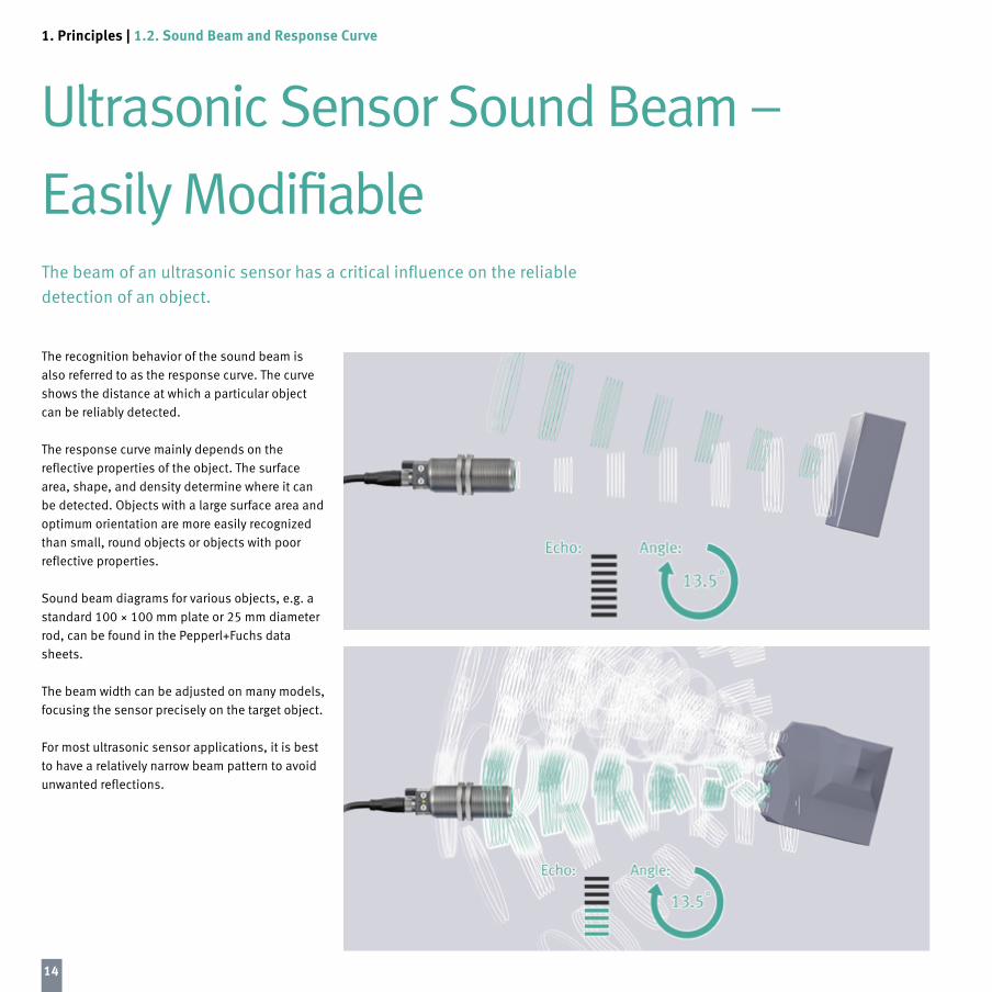
The beam of an ultrasonic sensor has a critical influence on the reliable detection of an object.
The recognition behavior of the sound beam is also referred to as the response curve. The curve shows the distance at which a particular object can be reliably detected.
The response curve mainly depends on the reflective properties of the object. The surface area, shape, and density determine where it can be detected. Objects with a large surface area and optimum orientation are more easily recognized than small, round objects or objects with poor reflective properties.
Sound beam diagrams for various objects, e.g. a standard 100 × 100 mm plate or 25 mm diameter rod, can be found in the Pepperl+Fuchs data sheets.
The beam width can be adjusted on many models, focusing the sensor precisely on the target object.
For most ultrasonic sensor applications, it is best to have a relatively narrow beam pattern to avoid unwanted reflections.

15
Object Shape and Surface
A major advantage of ultrasonic detection is its ability to recognize most materials and surfaces. Color is of no consequence. Ultrasonic sensors can detect solids, liquids, or powders. Surface properties have no effect on the reliability of detection. It doesn’t matter if the surface is rough, smooth, high gloss, or transparent. Surfaces can also be dirty, wet, or dry.
Level, smooth surfaces at right angles to the sensor axis return the best reflections. If the angle to the surface object is not 90°, the returning sound can be deflected away from the transducer, and it will no longer be detectable.
Larger angle deviations are possible when recording rough or uneven surfaces.
The amplitude of the reflected ultrasonic signal must be high enough to allow reliable measurement.
Similarly, high levels of dust and humidity reduce the acoustic energy and can reduce the maximum range of the ultrasonic sensor.
Temperature and Humidity
The range of ultrasonic signals is also influenced by the relative humidity and temperature of the ambient air. Generally speaking, the sensing range decreases with increasing temperature and increasing humidity. This reduction is not linear and differs from sensor to sensor.
1.2.1. FactorsInfluencingtheSoundBeam
Dust, Rain, and Snow
Heavy dust, rain, or snow reduce acoustic energy and can diminish the beam or reduce the maxi-mum range of ultrasonic sensors.
Light dust and dirt deposits on the transducer surface will not influence measurement. Accumulation of water, snow, and ice must be prevented with proper installation (i.e. protective enclosures).
Sou
nd b
eam
wid
th in
mm
Distance in mm
0
–1,000
2,000
1,000
–2,000
0 1,000 2,000 3,000 4,000 5,000 6,000 7,000 8,000 9,000 10,000 11,000 12,000
20°C, 0% humidity, wide sound beam with 11 m range70°C, 20% humidity, small sound beam with 4 m range

16
1. Principles | 1.2. Sound Beam and Response Curve
1.2.3. SoundBeamModification
Ultrasonic sensors with adjustable sound beams allow the sensing threshold to be customized. The sensing range can be adjusted to suit the object being detected via programming software or a Teach-In function.
Pepperl+Fuchs’ ultrasonic sensors are programmed using the ULTRA3000, SONPROG, PACTware (IO-Link), or ULTRA-PROG-IR software.
They enable precise control of the overall acoustic beam width. This means that the beam can be reduced in both length (axial sound beam) and width (lateral sound beam).
Lateral and axial sound beam width can also be adjusted independently. This allows disruptive or reflective objects within the sensing range to be suppressed.
Reducing the sound beam size allows disruptive objects or attachments on machines or in tanks to be suppressed.
Axial sound beam modification and lateral sound beam modification.
Axial sound beam modification.
Lateral sound beam modification.

17
1. Grundlagen | 1.2 Schallkeule und Ansprechkurve
With the ULTRA-PROG-IR software, disruptive objects can also be suppressed using specific programming of blind zones without modifying the beam.The object can no longer be detected in this blind zone.

18
The Right Sensor for Every Application
1. Principles | 1.3. Operating Modes
Pepperl+Fuchs’ ultrasonic sensors determine the distance to an object using the echo transit time method. The measured distance can be evaluated and displayed in different ways.
The distance to the object is converted into an analog value and displayed at the sensor’s analog output (e.g. 0–10 V, 4–20 mA).
Ultrasonic sensor in diffuse mode.
Alternatively, the object distance can be directly transmitted to a controller as a digital value via a special interface (e.g. IO-Link).

19
For ultrasonic sensors with switching outputs, the output state changes when an object is detected within the set switching range. A distinction is also made between NO and NC functions, depending on the response to the object.
For sensors with switching outputs, different operating modes can be set using appropriate assembly and configuration.
1.3.1. DiffuseModeSensors
Ultrasonic sensors are most commonly used in diffuse mode.
The emitter and receiver are located in the same housing. The target acts as a sound reflector.
Properties
n Easy to install, only one sensor head
n Foreground and background suppression possible (window mode)
n Object serves as a reflector, alignment is important
n Switching frequency is lower compared to a thru-beam sensor
Level measurement in a tank using an ultrasonic sensor.

20
1. Principles | 1.3. Operating Modes
1.3.2. RetroreflectiveSensors
In retroreflective mode, the ultrasonic transducer is also used as an emitter and receiver.
Unlike diffuse mode sensors, the ultrasonic signal is constantly reflected by a permanently installed reflector.
An aligned metal or plastic panel can be used as a reflector. An existing background such as a wall, conveyor belt, or the floor can also be used.
As long as there is no object between the sensor and reference reflector, the sensor receives a constant echo from the reflector. When a detected object enters the sensing range, the reflection of the ultrasound signal changes and the sensor detects the presence of the object.
Ultrasonic sensor in retroreflective mode.

21
In general, the following three scenarios will trigger switching:
1. A small object located in front of the reference reflector is detected by the sensor, i.e. the ultrasonic sensor receives an additional echo from the reference reflector.
2. A large object is detected and completely obscures the reference reflector, i.e. the ultrasound sensor receives an echo only from the large object and no echo from the reference reflector.
3. A large, slanted object in front of the reference reflector is not detected but obscures the reflector, i.e. the ultrasonic sensor does not receive an echo from the object or the reference sensor.
All three scenarios trigger switching at the ultrasonic sensor output.
Retroreflective sensors are especially recommended for reliable detection of sound-absorbing objects. They are also suitable for objects without reliably detectable surfaces, e.g. smooth, slanted surfaces such as a car windshield. There are no blind zones in this operating mode.
Properties
n Easy to install, only one sensor head
n Reliably detects problematic objects (sound-absorbing, slanted surfaces)
n Reference object/background is used as a fixed reflector; the object disturbs/breaks the beam
n Switching frequency is lower compared to a thru-beam sensor
Reliable detection of a slanted object on a conveyor belt by using the retroreflective mode.

22
1.3.3. Thru-Beam Sensors
Ultrasonic thru-beam sensors use dedicated emitter and receiver transducers contained in two separate housings. The evaluation electronics and outputs are housed with the receiver.
The sensors are mounted opposite one another on a common axis. When an object interrupts the sound beam, the sensor switching output is activated.
The receiver sensitivity can usually be set (Teach-In, potentiometer) for different intervals between the emitter and receiver and/or for different object sizes.
1. Principles | 1.3. Operating Modes
This mode is extremely resistant to external disturbances. It also doubles the range and enables objects to be reliably detected at significantly greater distances. The switching frequency is considerably faster, as the sensor does not have to continuously switch between transmission and reception modes.
Properties
n Two sensor heads must be installed and wired
n Long range, i.e. large distance between emitter and receiver possible
n Reliably detects problematic objects (sound-absorbing, slanted surfaces)
n Very high switching frequency, defined response characteristics
Ultrasonic sensor in thru-beam mode.

23
1. Grundlagen | 1.3 Betriebsarten
A very high switching frequency is required for bottle counting.

24
Switching Output Configuration 1. Principles | 1.4. Switching Outputs
One or more switching points can be set within the sensing range of an ultrasonic sensor. This can be done via a potentiometer, Teach-In, or programming software.
If an object is located within the set range, the sensor’s digital output state changes. A distinction is made between NO and NC functions, depending on the response to the object.
The following operating modes can be set by programming or using the Teach-In function:
Background Suppression, One Switching Point
One switching point can be set within the sensing range. If an object is located between the sensor head (blind zone) and the set switching point, the switching output will react. Objects behind the switching point are suppressed. This mode is therefore known as background suppression.
In this mode, only objects before the set switching point are detected: the background is suppressed.
Window Mode, Two Switching Points
Two switching points can be set within the sensing range. The two switching points form a switching window. Objects within the window cause a reaction at the switching output.
In this mode, objects are detected only within a defined area: foreground and background are suppressed.
Background suppression, switching mode. Foreground and background suppression (window mode).
Foreground suppressed
Background suppressed
Background suppressed
Switching point Switching point
Switching point

25
Output Activity
A distinction is made between PNP output and NPN output, depending on whether the load is on the positive supply voltage (L+) or the negative supply voltage (L–).
PNP The output stage contains a PNP transistor that switches the load to the positive supply voltage (L+). The load is connected between the output and the negative supply voltage (L–).
NPN The output stage contains an NPN transistor that switches the load to the negative supply voltage (L–). The load is connected between the output and the positive supply voltage (L+).
1
4
3
1
2
3
1L+
L–
4
3
1.4.1. Variants
Switching Behavior (Output Function)
Two different switching behaviors are available. They correspond to the behavior of a switch with normally open or normally closed functions.
Normally Open (NO) Contact The output switches on if there is an object located in the switching area. If there is no object in the switching area, the output switches off.
Normally Closed (NC) Contact The output switches on if there is no object located in the switching area. If there is an object in the switching area, the output switches off.
Push-Pull The output stage contains a PNP and an NPN transistor. The load is connected between the output and the negative supply voltage (L–) or the positive supply voltage (L+).
1
L–
L+
4
3
1
4
3
+UB
–UB

26
Switching Hysteresis
Every switching point has switching hysteresis to prevent the output from constantly switching on and off when an object is located directly at the switching point.
If an object approaches the sensor, the output triggers directly at the switching point. When the object recedes again, the hysteresis is added to the switching point.
1. Principles | 1.4. Switching Outputs
Switching Frequency
The switching frequency is the maximum number of possible switching cycles per second. For example, a switching frequency of 5 Hz means that the output can change state from on to off and back on again five times per second.
Due to the measuring method used (echo transit time), the switching frequency of ultrasonic sensors is usually in the range of <10 Hz.
Values up to approximately 100 Hz are possible for thru-beam sensors with separate emitter and receiver transducers.
1.4.2. Switching Hysteresis, Switching Frequency, and Repeatability
Repeatability (Reproducibility)
Repeatability, also known as reproducibility, refers to natural variances in the switching point under specific conditions.
Repeatability is measured over a period of eight hours at an ambient temperature of 23°C (±5°C), with any relative humidity within the specified range, and at a specified supply voltage.
An ultrasonic sensor guarantees proper container filling. The hysteresis prevents a flickering switching output.
Illustration of an ultrasonic sensor’s switching hysteresis.
Hyst
eres
is
Defined switching point

27
1. Grundlagen | 1.4 Schaltausgang

28
Analog Output – Function and Variants
1. Principles | 1.5. Analog Output
An ultrasonic sensor does not merely detect the presence of an object – it also measures the distance to an object. This is calculated from the interval between the transmission of the ultrasonic signal and the arrival of the echo.
Ultrasonic sensor analog outputs produce a linear current or voltage signal. The signal level is proportional to the distance between a detected object and the sensor. The output current is between 0 and 20 mA or 4 and 20 mA, depending on the model. For analog voltage versions, the range is between 0 and 10 V.
A rising slope (analog value increases with increasing distance) or falling slope (analog value decreases with increasing distance) can be selected.
1.5.1. Variants
Current Output 0–20 mA
The distance to an object is represented at the analog output as a current value in the range of 0–20 mA.
The specified load resistance must not be exceeded, e.g. <300 ohm.
Current Output 4–20 mA
The distance to an object is represented at the analog output as a current value in the range of 4–20 mA.
Here, too, the specified load resistance must not be exceeded, e.g. <300 ohm.
Voltage Output 0–10 V
The distance of an object is represented at the analog output as a voltage value in the range of 0–10 V.
It must not fall short of the specified load resistance, e.g. >500 ohm.
Frequency Output in Hz
The distance to an object is represented at the analog output as a variable frequency value in hertz.
The output displays a square wave pulse (24 V/0 V). The specified load resistance must be met, e.g. >500 ohm.
29
1.5.2. Characteristic Curve
The Teach-In function or programming software can be used to set a rising or falling characteristic curve or a zero-point line on the sensor.
With a rising characteristic curve, the output current or voltage increases as the object increases in distance from the beginning of the analog area.
With a falling characteristic curve, the output current or voltage decreases as the object increases in distance from the beginning of the analog area.
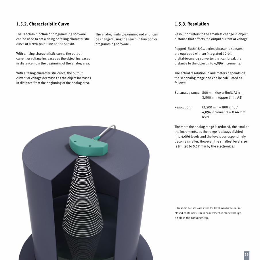
1.5.3. Resolution
Resolution refers to the smallest change in object distance that affects the output current or voltage.
Pepperl+Fuchs’ UC… series ultrasonic sensors are equipped with an integrated 12-bit digital-to-analog converter that can break the distance to the object into 4,096 increments.
The actual resolution in millimeters depends on the set analog range and can be calculated as follows:
Set analog range: 800 mm (lower limit, A1); 3,500 mm (upper limit, A2)
Resolution: (3,500 mm – 800 mm) / 4,096 increments = 0.66 mm level
The more the analog range is reduced, the smaller the increments, as the range is always divided into 4,096 levels and the levels correspondingly become smaller. However, the smallest level size is limited to 0.17 mm by the electronics.
The analog limits (beginning and end) can be changed using the Teach-In function or programming software.
Ultrasonic sensors are ideal for level measurement in closed containers. The measurement is made through a hole in the container cap.
30
Influences on the Measurement Accuracy of the Ultrasonic Sensor
1. Principles | 1.6.InfluencingFactors
With ultrasonic sensors, measurement accuracy usually refers to the absolute accuracy of the measured value at the analog output. Based on the echo transit time, the measurement accuracy of an ultrasonic sensor depends on several physical parameters relating to the air as well as internal tolerances.
1.6.1.EnvironmentalInfluences
Air Temperature
Air temperature has the greatest influence on measuring accuracy.
After the transit time of the reflected ultrasonic impulse has been measured, the sensor calculates the distance to the object using the speed of sound. However, as the air temperature changes, the speed of sound changes by 0.17% per degree Kelvin. To compensate for this effect, almost all Pepperl+Fuchs’ ultrasonic sensors have a temperature probe. The probe measures the ambient temperature and the sensor corrects the temperature-related distortion of the measured values (see temperature compensation).
Humidity
Humidity has negligible influence on the speed of sound at room temperature and at lower temperatures. However, at higher air temperatures, the speed of sound increases as humidity increases.
Air Pressure
The speed of sound decreases by less than 1% between sea level and 3,000 m altitude. Atmospheric fluctuations at a specific location are negligible and the effects on the speed of sound are scarcely measurable.

31
Air Currents
Normal air currents (wind) have no effect on ultrasonic measurement up to wind force 7 (50–61.5 km/h) if the object has the reflective properties of the standard reflector. Stormy weather or hurricanes can cause unstable measurements (with loss of signal).
No general conclusions can be drawn with regard to changes in the speed of sound caused by constant changes of air current direction and air current speeds. For example, it is known that particularly hot objects, such as red-hot metal, cause significant air turbulence. The ultrasound can be scattered or deflected in such a way that no evaluable echo is returned.
Paint Mist
Paint mist has no detectable effect on the operation of ultrasonic sensors. However, the mist should not be allowed to settle on the active transducer surface to avoid compromising the transducer’s sensitivity.
External Noise
External noise is distinguished from the desired target echoes and generally does not cause malfunctions. If the source of disturbance has the same frequency as the ultrasonic sensor, the level of the external noise must not exceed the level of the target echoes. This can occur, for example, when filling a silo with stone.
Types of Gas
Pepperl+Fuchs’ ultrasonic sensors are designed for operation in atmospheric air. Operation in other gases (e.g. in carbon dioxide) can cause serious errors of measurement or even total loss of function due to deviations in the speed of sound and attenuation.

32
1. Grundlagen | 1.6Einflussgrößen
33
1. Principles | 1.6.InfluencingFactors
1.6.2. Temperature Compensation
Ultrasonic sensors operate using the echo transit time method: the time elapsed between the emitted ultrasonic pulse and when the received echo is evaluated. The ultrasonic sensor calculates the distance of the object from the speed of sound.
When sound is propagated in air, the speed of sound is about 344 m/s at room temperature.
However, the speed of sound is temperature-dependent and changes by approximately 0.17% with each degree Celsius.
Such changes affect the transit time and can distort the calculated distance.
Most Pepperl+Fuchs ultrasonic sensors have a working range of –25°C to +70°C.
Without temperature compensation and at a measuring distance of 100 cm, a 20°C change in temperature would cause a measurement error of –8.5 cm at 70°C and +7.65 cm at –25°C.
Therefore, most Pepperl+Fuchs ultrasonic sensors are equipped with temperature probes whose measurements are used to correct the measured distances. This compensation is performed over the entire working range of the ultrasonic sensors from –25°C to +70°C and allows measurement accuracies of approximately ±1.5% to be achieved.
1.6.3. Accuracy
Accuracy/absolute accuracy refers to the difference between the output value measured by the sensor and the actual target distance.
From a practical viewpoint, absolute accuracies of 1% to 3% are realistic in industrial applications for ultrasonic sensors in the operating range of –25°C to +70°C.
Higher accuracies can be achieved in very stable ambient conditions. In this case, it is advisable to turn off temperature compensation (using the programming tool).
Another possibility would be to use an ultrasonic reference sensor.
This involves mounting a second sensor of the same type parallel to the measuring sensor and aligning it to a fixed object. If ambient conditions in the measuring range change, the distance to the object will also appear to change due to the altered speed of sound. The measuring sensor value must then be corrected by the value of this error.
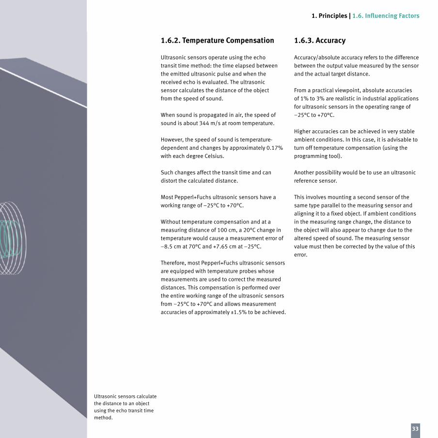
Ultrasonic sensors calculate the distance to an object using the echo transit time method.

34
Simple Installation and Assembly1. Principles | 1.7. Installation and Assembly
Ultrasonic sensors can be installed and operated in any position. However, mounting conditions where materials can settle on the transducer surface should be avoided.
1.7.1. Operation and Object Properties
Direction of Actuation
The objects being detected can enter the sound beam from any side. The anticipated detection points can be accurately approximated using the ranges and response curves specified in the data sheets.
Object Surface Properties
Ultrasonic sensors can detect solids, liquids, and powders. The surface properties of the object are critical for the sensor’s evaluation of the echoes. Level, smooth surfaces at right angles to the beam produce ideal reflections. The angular deviation of the measurement plate must not exceed approximately 3° to ensure reliable detection.
Material properties such as transparency, color, or surface treatment (polished or matte) have no effect on detection reliability. Rough surfaces reflect the acoustic energy in multiple directions, decreasing the overall detection range.
When cleaning ultrasonic sensors, ensure that the sensor surface (decoupling layer) and the integrated foam around the transducer are not damaged. Water droplets or crusting on the decoupling layer may impair the function of the ultrasonic sensor. Light dust deposits are not critical.
Conversely, rough surfaces allow greater angular deviation due to the predominantly diffuse reflection of the ultrasound signal.
This can be used to detect filling levels or heaps of coarse-grained materials with an angular deviation of up to 45° (at a reduced range).
The following objects can be detected particularly well:
n All smooth and solid objects aligned perpendicularly to the beam angle
n All solid objects with a surface roughness that cause diffuse reflections and that are randomly aligned
n Surfaces of liquids at an angle <3° from the beam axis
35
1. Grundlagen | 1.7 Einbau und Montagehinweise
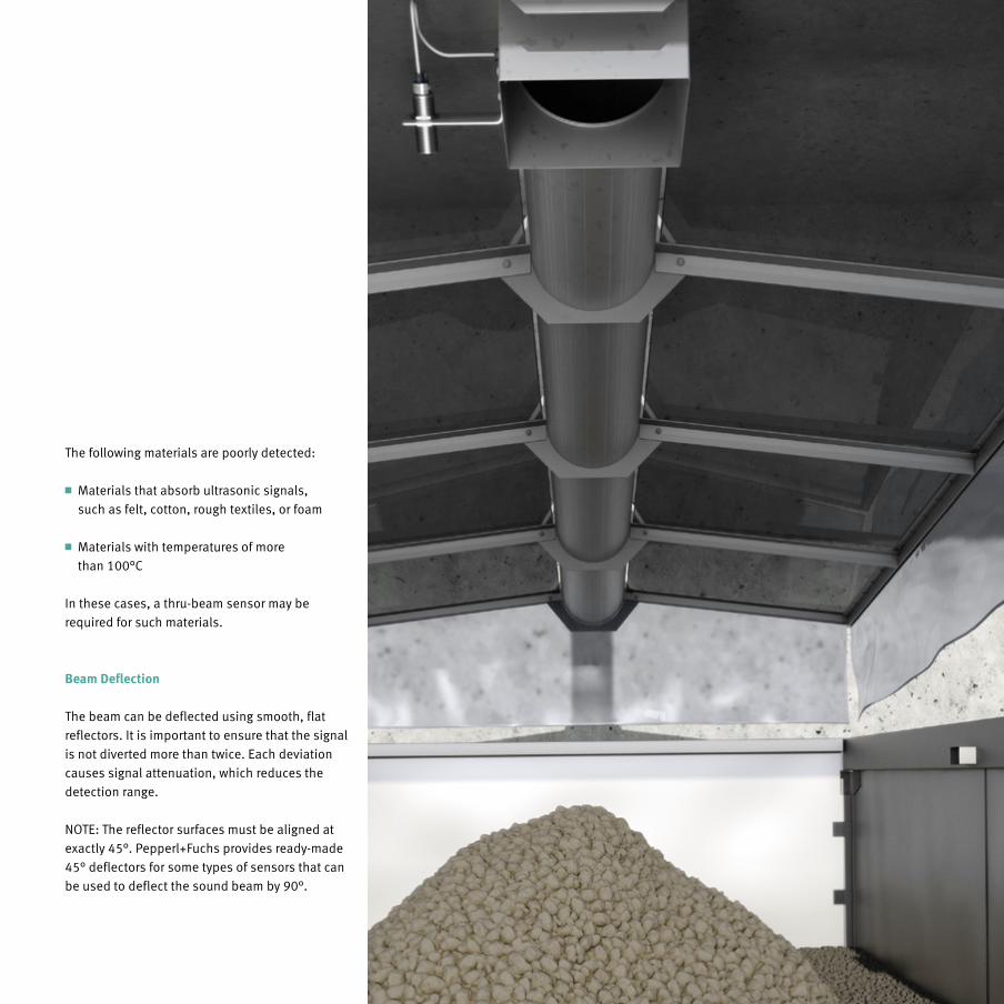
The following materials are poorly detected:
n Materials that absorb ultrasonic signals, such as felt, cotton, rough textiles, or foam
n Materials with temperatures of more than 100°C
In these cases, a thru-beam sensor may be required for such materials.
Beam Deflection
The beam can be deflected using smooth, flat reflectors. It is important to ensure that the signal is not diverted more than twice. Each deviation causes signal attenuation, which reduces the detection range.
NOTE: The reflector surfaces must be aligned at exactly 45°. Pepperl+Fuchs provides ready-made 45° deflectors for some types of sensors that can be used to deflect the sound beam by 90°.

36
1. Principles | 1.7. Installation and Assembly
1.7.2. Sound Beam and Clearance
Sound Beam
The response curve of ultrasonic sensors is referred to as a sound beam.
Objects are detected within the sound beam if they reflect sufficient sound back to the sensor. The response curve depends on the reflective properties of the object. Therefore, sound beam diagrams are provided for various standard objects in the data sheets.
The sound beam has no precisely defined limits and can change due to environmental influences such as temperature or humidity.
Clearance
If unwanted acoustically reflective objects are present in an application, there must be clearance around the sound beam. This is the only way to avoid incorrect switching caused by unintended reflections.
Response curve 2 (25 mm round bar) can be used for orientation in the case of small, round, or poorly reflective objects. It can also be used for smooth surfaces that are mounted parallel to the sensor’s beam direction (container inner wall, pipes). Clearance corresponding to at least response curve 1 (flat panel 100 mm × 100 mm) must be provided for larger objects with good reflection properties (interfering edges).
If clearances cannot be maintained, many Pepperl+Fuchs sensors provide the option of modifying the sound beam (see Sound Beam chapter).
This can be performed using Teach-In buttons or with a programming interface and corresponding software. The software can be used to selectively suppress many interfering objects within the sensing range (fixed-target suppression).
Flat surface, 100 mm × 100 mm Round bar, Ø 25 mm
37
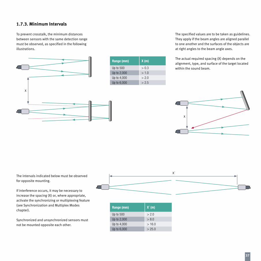
1.7.3. Minimum Intervals
To prevent crosstalk, the minimum distances between sensors with the same detection range must be observed, as specified in the following illustrations.
The specified values are to be taken as guidelines. They apply if the beam angles are aligned parallel to one another and the surfaces of the objects are at right angles to the beam angle axes.
The actual required spacing (X) depends on the alignment, type, and surface of the target located within the sound beam.
X
Range (mm) X (m)
Up to 500 > 0.3
Up to 2,000 > 1.0
Up to 4,000 > 2.0
Up to 6,000 > 2.5
X
The intervals indicated below must be observed for opposite mounting.
If interference occurs, it may be necessary to increase the spacing (X) or, where appropriate, activate the synchronizing or multiplexing feature (see Synchronization and Multiplex Modes chapter).
Synchronized and unsynchronized sensors must not be mounted opposite each other.
X΄
Range (mm) X´ (m)
Up to 500 > 2.0
Up to 2,000 > 8.0
Up to 4,000 > 16.0
Up to 6,000 > 25.0

38
1. Principles | 1.8. Synchronization and Multiplex Modes
Synchronizing Ultrasonic Sensors
When installing ultrasonic sensors, it may not be possible to adhere to the minimum separation distances.Pepperl+Fuchs provides models with synchronization inputs. This prevents sensor crosstalk and allows the minimum separation distance to be reduced.
Ultrasonic sensors equipped with synchronization inputs can be used in internal or external synchronization or multiplex modes.
By synchronizing the transmission cycles, the distance between adjacent sensors can be reduced without interference.
Synchronization can be achieved using an external synchronization signal or, for some sensor types, using self-synchronization or multiplexing.
1.8.1. Synchronization Input
Many Pepperl+Fuchs sensors are equipped with an additional synchronization connection.
If this input remains open, the sensor will operate in normal mode.
By applying a defined potential (L+/L–), the sensor can be locked and enabled again using an external trigger signal. As long as the sensor is locked, no ultrasonic pulses are emitted.
The outputs (analog and switching outputs) are frozen while in this state.
As soon as the sensor is enabled for at least one measurement cycle with the synchronization input, the outputs are updated. This feature can be used for external synchronization or multiplex operation.
In external synchronization mode, the synchronization inputs for all sensors are linked and controlled by an external clock-pulse source (each sensor is triggered separately in multiplex mode).
The required signal level, cycle times, and the maximum possible number of sensors can be found in the data sheet of the respective sensor. In internal synchronization mode, the synchronization inputs for all sensors are linked and controlled by the sensors themselves. There is no need for an external clock-pulse source.
1.8.2. Synchronization and Common Mode
In this mode, the sensors work in parallel. This means they all emit a burst of ultrasound at the same time and wait for a reflected echo from an object within the sensing range.
To do this, the synchronization inputs of all sensors must be connected to one another.
Depending on the sensor type/family and configuration, synchronization mode either runs automatically (internal synchronization) or requires an external trigger signal (external synchronization).
39
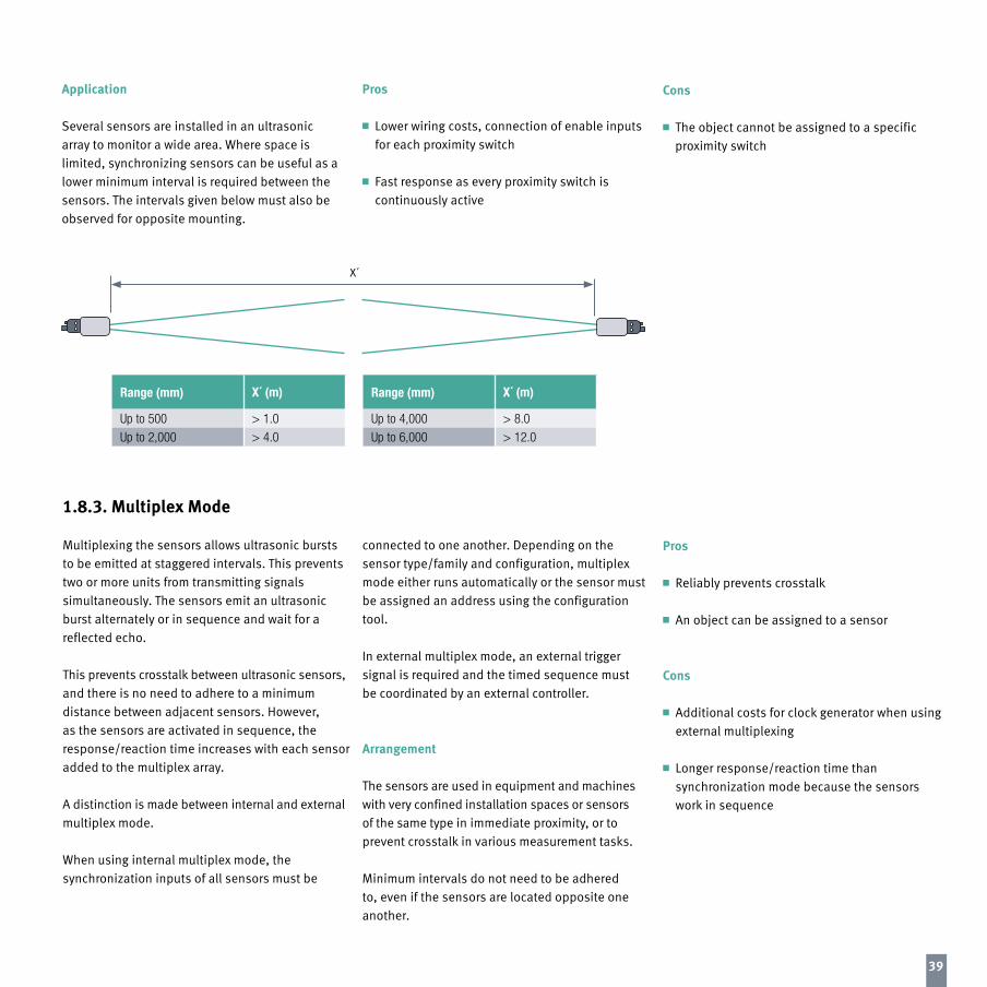
1.8.3. Multiplex Mode
Multiplexing the sensors allows ultrasonic bursts to be emitted at staggered intervals. This prevents two or more units from transmitting signals simultaneously. The sensors emit an ultrasonic burst alternately or in sequence and wait for a reflected echo.
This prevents crosstalk between ultrasonic sensors, and there is no need to adhere to a minimum distance between adjacent sensors. However, as the sensors are activated in sequence, the response/reaction time increases with each sensor added to the multiplex array.
A distinction is made between internal and external multiplex mode.
When using internal multiplex mode, the synchronization inputs of all sensors must be
connected to one another. Depending on the sensor type/family and configuration, multiplex mode either runs automatically or the sensor must be assigned an address using the configuration tool.
In external multiplex mode, an external trigger signal is required and the timed sequence must be coordinated by an external controller.
Arrangement
The sensors are used in equipment and machines with very confined installation spaces or sensors of the same type in immediate proximity, or to prevent crosstalk in various measurement tasks.
Minimum intervals do not need to be adhered to, even if the sensors are located opposite one another.
Application
Several sensors are installed in an ultrasonic array to monitor a wide area. Where space is limited, synchronizing sensors can be useful as a lower minimum interval is required between the sensors. The intervals given below must also be observed for opposite mounting.
Pros
n Lower wiring costs, connection of enable inputs for each proximity switch
n Fast response as every proximity switch is continuously active
Cons
n The object cannot be assigned to a specific proximity switch
Pros
n Reliably prevents crosstalk
n An object can be assigned to a sensor
Cons
n Additional costs for clock generator when using external multiplexing
n Longer response/reaction time than synchronization mode because the sensors work in sequence
X΄
Range (mm) X´ (m)
Up to 500 > 1.0
Up to 2,000 > 4.0
Range (mm) X´ (m)
Up to 4,000 > 8.0
Up to 6,000 > 12.0

40
Ultrasonic Sensors in Various ApplicationsUltrasonic sensors are an impressive group of sensors. They are functionally robust, available in a variety of designs, and open up a wide range of uses, from factory automation to mobile equipment, with some of the toughest and most extreme applications on the market.
Level Measurement
Because ultrasonics calculate level height using the time it takes for ultrasonic pulses to travel from the sensor to the medium surface and back, the chemical and physical properties of the product do not affect the measurement. Milk, paint, fertilizers, and chemicals, as well as mud or bulk goods are measured with equal accuracy.
Mobile Equipment
To survive the rigorous electrical and environmental world inherent in outdoor mobile equipment, Pepperl+Fuchs’ mobile equipment sensors must be qualified to standards far beyond traditional sensors. Ultrasonic sensors designed for mobile equipment thrive in rugged outdoor environments.
Immune to the effects of dust, dirt, and chemicals, ultrasonic sensors also provide reliable operation in modern agriculture applications. Ultrasonics effectively monitor crop height, distance to the ground, and levels of seeds and grains.

41
Food and Beverage
Ultrasonic sensors made for the food and beverage industry are designed according to the EHEDG guidelines for hygienic design. They have a 1.4404 (V4A)/AISI 316L housing, an impermeable metal face, and offer IP68/IP69k protection for demanding production and cleaning.
Material Handling
Automatic processes in logistics, production, and processing require robust and reliable sensor solutions that cover a wide range of applications. Ultrasonic sensors offer a host of advantages here. Our broad ultrasonic product offering ranges from simple, miniature presence detection models, to high-end analog, software-configurable designs with customizable beam patterns and stability algorithms.
Doors, Gates, and Elevators
In parking lots and in parking garages, entry is controlled using barrier gate arm systems. The gate arm must not be lowered when there is a vehicle underneath. Ultrasonic sensors are particularly suitable for controlling this procedure.
They detect objects regardless of vehicle type or color and monitor the entire area below the arm. Retroreflective mode ultrasonics are used in parking garages to count vehicles and determine available parking spaces.
42
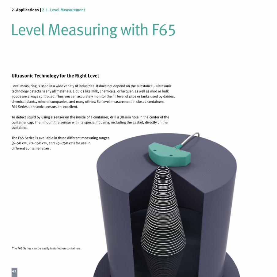
Level Measuring with F652. Applications | 2.1. Level Measurement
The F65 Series can be easily installed on containers.
Ultrasonic Technology for the Right Level
Level measuring is used in a wide variety of industries. It does not depend on the substance – ultrasonic technology detects nearly all materials. Liquids like milk, chemicals, or lacquer, as well as mud or bulk goods are always controlled. Thus you can accurately monitor the fill level of silos or tanks used by dairies, chemical plants, mineral companies, and many others. For level measurement in closed containers, F65 Series ultrasonic sensors are excellent.
To detect liquid by using a sensor on the inside of a container, drill a 30 mm hole in the center of the container cap. Then mount the sensor with its special housing, including the gasket, directly on the container.
The F65 Series is available in three different measuring ranges (6–50 cm, 20–150 cm, and 25–250 cm) for use in different container sizes.
43
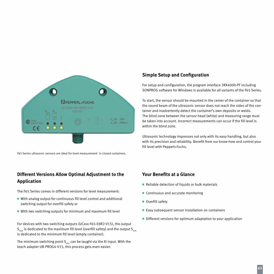
F65 Series ultrasonic sensors are ideal for level measurement in closed containers.
DifferentVersionsAllowOptimalAdjustmenttothe Application
The F65 Series comes in different versions for level measurement:
n With analog output for continuous fill level control and additional switching output for overfill safety or
n With two switching outputs for minimum and maximum fill level
For devices with two switching outputs (UCxxx-F65-E8R2-V15), the output Smax is dedicated to the maximum fill level (overfill safety) and the output Smin is dedicated to the minimum fill level (empty container).
The minimum switching point Smin can be taught via the XI input. With the teach adapter UB-PROG4-V15, this process gets even easier.
SimpleSetupandConfiguration
For setup and configuration, the program interface 3RX4000-PF including SONPROG software for Windows is available for all variants of the F65 Series.
To start, the sensor should be mounted in the center of the container so that the sound beam of the ultrasonic sensor does not reach the sides of the con-tainer and inadvertently detect the container’s own deposits or welds.The blind zone between the sensor head (white) and measuring range must be taken into account. Incorrect measurements can occur if the fill level is within the blind zone.
Ultrasonic technology impresses not only with its easy handling, but also with its precision and reliability. Benefit from our know-how and control your fill level with Pepperl+Fuchs.
YourBenefitsataGlance
n Reliable detection of liquids or bulk materials
n Continuous and accurate monitoring
n Overfill safety
n Easy subsequent sensor installation on containers
n Different versions for optimum adaptation to your application

44
Fill Level Monitoring in Gravel Silos
2. Applications | 2.1. Level Measurement
Stay Well Informed with Ultrasonic Sensor Series F260
Gravel open-cast mines contain various construction materials such as sand, crushed rock, and gravel. These materials are excavated at depths of up to 50 m and must be appropriately stored until they can be transported from the site. Conveyor belts transport the construction materials to silos. Ultrasonic sensors determine when the maximum fill level of a silo is reached. The F260 Series is particularly suitable for this application.
By means of ultrasonic time-of-flight measurement, the sensors determine the distance to the surface of the filled material and transmit this value to the control room for the gravel silo. There, further filling can be stopped and overfilling prevented. The analog output of the ultrasonic sensor controls this process. In addition, the devices feature two switching outputs. One output provides an advance warning that the maximum fill level of the silo will soon be reached. The other switching output provides for final shutdown as soon as the silo is completely filled.
The detection range of these sensors is up to 10 m. The sensors can monitor the continuous filling of the silo at all times. This series is especially characterized by the wide temperature range of –25°C to +70°C. When used in crushed-rock silos that generate high amounts of dust, the maximum detection range of the 10 m sensors may be reduced to 6 m.
The F260 Series offers the following versions for the analog output (including two switching outputs in the NO or NC contact version):n 4–20 mA, UCxxx-F65-IE..-V15n 0–10 V, UC10000-F260-UE..-V15Furthermore, the 3RX4000-PF programming interface including SONPROG software for Windows is available for the commissioning and parameterization of all versions.
In Kiesbunkern werden Ultraschallsensoren zur kontinuierlichen Füllstandskontrolle eingesetzt
In gravel silos, ultrasonic sensors are used for continuous fill level measurement.

45
YourBenefitsataGlance
n Extremely robust design with high excess gain
n Mounting flange with swiveling bracket for optimum alignment of the sensor head
n Simple commissioning through viewing with SONPROG and 3RX4000-PF
n Continuous fill-status monitoring
n Reliable shutdown of the conveyor belt prevents overfilling
Important for Implementation
Mount the sensor right in the center of the silo so that the sound beam does not reach the sides of the container walls, where the sides of the walls themselves or slag sticking to the walls may inadvertently be detected.To ensure adequate sound reflection as the fill level increases, align the sensor’s sound beam at a slight angle toward the center of the material cone. The F260 can be swiveled up to 10° in its bracket.
The blind zone between the sensor head (white) and the start of the measuring range (80 cm) must also be taken into account. If the fill level is located in this area, measurement errors may result. If two probes are installed, multiplex operation must be set using SONPROG and the sensors connected via the XI synchronization connector.
Filling under Control
Thanks to continuous level measurement in the control room, plant operators stay constantly informed of the current fill level in the gravel silo. The switching output of the F260 has an overfill protection function, switches the conveyor belt off, and prevents overfilling. Safe plant operation is therefore ensured at all times.

46
Stay Best Informed with Ultrasound
Waste water treatment produces enormous amounts of sewage sludge on a daily basis. This waste product has to be further processed or properly disposed of. Either way, it is necessary to load the material into appropriate transport containers. To prevent overfilling of the containers, this process is monitored using ultrasonic sensors.
The fill level is monitored by an ultrasonic sensor and output as an analog value. When the maximum fill level is reached, the sensor delivers an additional switching signal to stop the flow of the material.
The cone-shaped accumulation of bulk goods in containers calls for appropriate sensor mounting. To ensure adequate sound reflection as the fill level increases, align the sensor’s sound beam at a slight angle toward the center of the material cone. Depending on the measuring distance and requirement, you can use a sensor from the 30GM70 Series.
The UCC3500-30GH70-IE2R2-V15 ultrasonic sensor is ideal for this application. It features a measuring range of 20 to 350 cm, an analog output of 4 to 20 mA, and an additional switching output. It is therefore possible to ensure continuous level measurement and overfill protection from a larger distance.
Fill Level for Bulk Goods2. Applications | 2.1. Level Measurement
The 30GM70 Series prevents overfilling.

47
Simple Commissioning with ULTRA-PROG-IR Software
For commissioning and parameterization, we recommend the use of the UC-18/30GM-IR USB programming device and the ULTRA-PROG-IR program. This setup allows you to view the object distance and the echo signal strength and enables simple adaptation of the analog and switching point in the sensor.
To ensure a continuous measuring signal even with material slippage, program an average value of 250 to prevent sudden changes in the measured value. Thanks to continuous level measurement, waste water treatment plant operators stay constantly informed of the current fill level of the disposal containers in the control room and can ensure proper removal and emptying of full containers in a timely manner.
The 30GM sensor Series is especially impressive, with a high resistance to aggressive vapors as well as its PTFE-coated ultrasonic transducer and the V4A stainless-steel housing.
YourBenefitsataGlance
n Continuous level measurement
n Overfill protection
n Durable and robust sensor solution with V4A stainless-steel housing
n Simple commissioning and programming
The ultrasonic sensor Series 30GM70 continuously detects the height of the contents in the container and prevents overfilling.

48
Detecting Boom Height2. Applications | 2.2. Mobile Equipment
Ultrasonic Sensors Ensure Uniform Spray Coverage
Crop sprayers apply liquid fertilizers and pesticides over farmland during the growing period. Controlling the sprayer height is critical to this process. If the sprayer height is too high, the dispensed product may simply blow away in the wind. If too low, spray will not evenly distribute – or worse yet, a low sprayer mechanism can collide with the crops or ground.
Crop sprayer in action. Spray nozzles are mounted at defined intervals. Ultrasonic sensors control the boom height as the machinery crosses the field.
To ensure consistent, optimum spray coverage over uneven terrain and varying crop height, and to prevent the boom from impacting crops or soil, its height must be continuously monitored and adjusted.

49
Robust and Reliable
Immune to the effects of dust, dirt, and chemicals, and with the ability to detect surfaces of any color with identical accuracy, 30GM Series ultrasonic sensors are well suited for agricultural applications.
FastandEfficient
As the machinery traverses the field, 30GM Series ultrasonic sensors continuously monitor the distance to the crop canopy and transfer this reading as an analog value to the vehicle controller.The spray height is correspondingly raised or lowered to follow the contour, ensuring the fertilizer and pesticide distribution remains consistent. With automated boom-height control, drivers can concentrate fully on navigating their machinery, finishing their job with optimum efficiency and speed.
YourBenefitsataGlance
n Automatic adjustment of boom height
n Fertilizers and pesticides are evenly spread
n Prevents crop and machinery damage
n Shorter cultivation time
n Rugged and durable
Feedback from the 30GM Series ultrasonic sensors enables liquid fertilizers and pesticides to be sprayed over the crops at a consistent height.

50
Anti-Collision Detection on Aerial Work Platforms
2. Applications | 2.2. Mobile Equipment
Indispensable on Construction Sites
Drivable aerial work platforms are increasingly common on many construction sites. These platforms facilitate working in high locations and increase productivity. However, since severe accidents involving aerial work platforms occur almost daily due to collisions, the safety aspect should not be ignored.
Ultrasonic sensors effectively safeguard the operation of this equipment. For the installation of ultrasonic sensors on the aerial work platforms, we recommend very flat housing designs like VariKont L2. Using these devices, you can monitor the area below the work platform, underneath the arms, and around the vehicle.
Collisions between the machine and obstacles such as trees, buildings, or people can therefore be prevented. If the ultrasonic sensors detect an object in close proximity, the machine switches to slow speed. In the case of acute danger of collision, machine movement stops completely.
Ultrasonic sensors of the VariKont L2 Series are ideal for installation on work platforms due to their compact design.

51
To safeguard the equipment, ultrasonic sensors are attached to the appropriate points on the aerial work platform.
Working Safely with Aerial Work Platforms
To safeguard the equipment, ultrasonic sensors are attached to the appropriate points on the aerial work platform. In order to prevent mutual interference of the sensors and simultaneously ensure the shortest possible response time, these sensors must be common-mode synchronized. As aerial work platforms are mostly used in outdoor applications, the sensors must be suitable for such an environment.
Monitoring the area below and around the machine ensures that collisions with other machines, buildings, or objects do not occur. Damage is prevented and machine availability is increased.
YourBenefitsataGlance
n Continuous monitoring of aerial work platforms
n Increased safety for workers and machines
n Prevention of damage to objects
n Increase in productivity

52
Ultrasonic Sensors on Spray Nozzles
2. Applications | 2.2. Mobile Equipment
Taking Care of Orchards with Ultrasonic Sensors
Taking care of orchards requires careful attention. For good harvests, it is necessary to protect the trees from pests. Since diseases as well as pests attack trees, it is even more important to ensure their survival and fertility. To help keep the trees alive, chemical products to protect trees are applied by a special spraying process.
These products, however, generate high costs for farmers. In order to sell the harvest for a reasonable price, the spraying operation must be carried out as efficiently as possible.
With the conventional method, pesticides are continuously sprayed – even in between the trees where there are only empty rows.
Using ultrasonic sensors can save on pesticides by detecting tree gaps. As soon as one of these gaps is recognized, the spraying process temporarily stops.
53
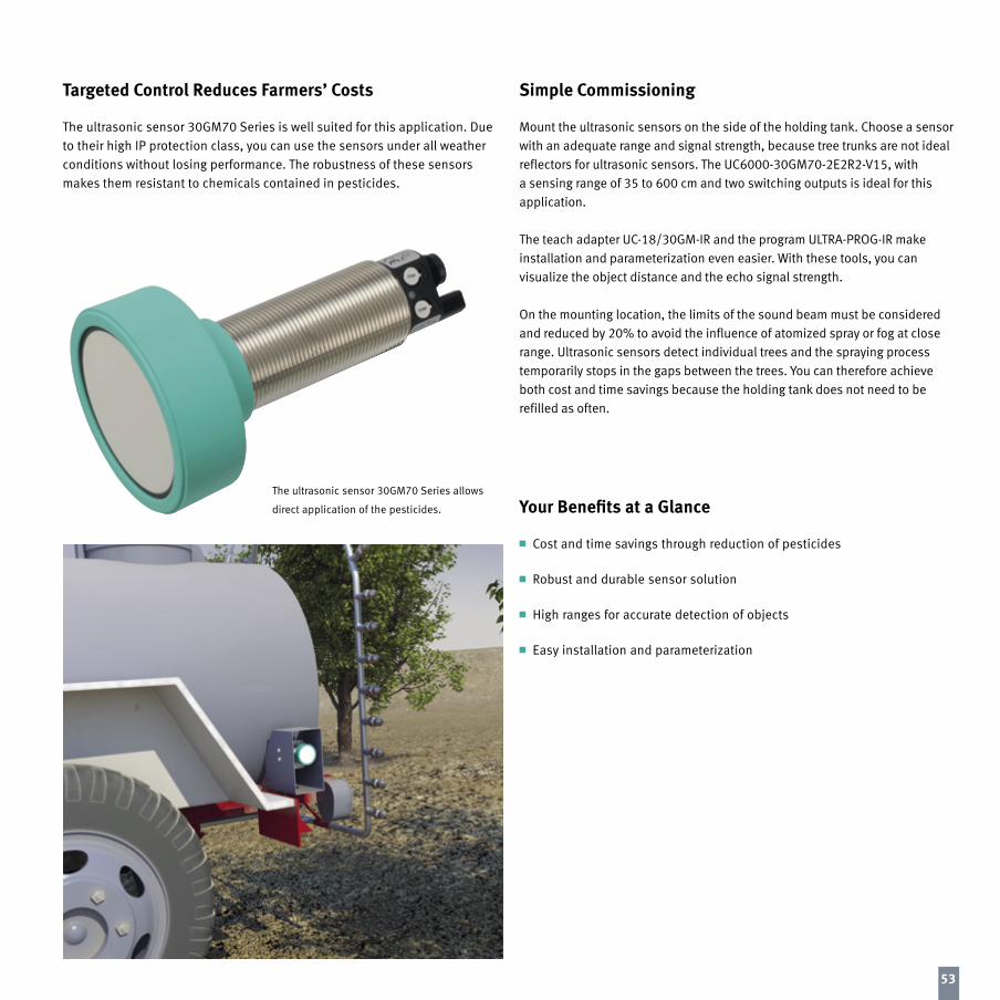
Simple Commissioning
Mount the ultrasonic sensors on the side of the holding tank. Choose a sensor with an adequate range and signal strength, because tree trunks are not ideal reflectors for ultrasonic sensors. The UC6000-30GM70-2E2R2-V15, with a sensing range of 35 to 600 cm and two switching outputs is ideal for this application.
The teach adapter UC-18/30GM-IR and the program ULTRA-PROG-IR make installation and parameterization even easier. With these tools, you can visualize the object distance and the echo signal strength.
On the mounting location, the limits of the sound beam must be considered and reduced by 20% to avoid the influence of atomized spray or fog at close range. Ultrasonic sensors detect individual trees and the spraying process temporarily stops in the gaps between the trees. You can therefore achieve both cost and time savings because the holding tank does not need to be refilled as often.
YourBenefitsataGlance
n Cost and time savings through reduction of pesticides
n Robust and durable sensor solution
n High ranges for accurate detection of objects
n Easy installation and parameterization
Targeted Control Reduces Farmers’ Costs
The ultrasonic sensor 30GM70 Series is well suited for this application. Due to their high IP protection class, you can use the sensors under all weather conditions without losing performance. The robustness of these sensors makes them resistant to chemicals contained in pesticides.
The ultrasonic sensor 30GM70 Series allows direct application of the pesticides.

54
Easy Control of Refuse Collection Vehicles
2. Applications | 2.2. Mobile Equipment
Ultrasonic Sensors Allow Safe Emptying Operations
For reliable operation, mobile machines require sensors that can withstand the harshest conditions on a daily basis. Extreme temperatures, violent jolting, and vibrations are common challenges for these vehicles.
Ultrasonic sensors, which are used on vehicles like refuse collection trucks, must be extremely robust to guarantee safe operation. The sensors are used on the vehicles for a range of different applications.
Ultrasonic sensors help ensure efficient and virtually automatic operation. These sensors constantly monitor the lifting and set-down area of the refuse container, as well as automatically detect the container size. These features provide an extraordinary degree of flexibility without manual intervention on the part of the refuse collector, ensuring that both the vehicle and the refuse collector can complete their work quickly and safely.

55
18GM40 Series Determines the Size of the Refuse Containers
When a refuse container moves toward the lifting unit of the refuse collection vehicle, the UB300-18GM40A ultrasonic sensor determines the size of the container. Both lifters are required to lift a large container with a volume of 1,100 l; the two lifters work together to transport the container. When two small containers or even a single small container are lifted, the lifters are controlled individually as required.
L2 Series for Safeguarding Lifting and Tipping Operations
When the container is lowered after emptying, the area below the container must be monitored. Monitoring is important to prevent people from being injured or other obstacles from being hit by the container and being damaged. A total of four UC2000-L2-type ultrasonic sensors monitor this area.
The 30GM70 Series Monitors the Contents of the Vehicle
The fill level of the feed area for the refuse container on the vehicle is monitored using UC2000-30GM70-type ultrasonic sensors in one-way barrier mode. If the feed area is too full, the container can no longer be emptied correctly and refuse may fall off the vehicle. For this reason, when the rear area is about to overflow, the vehicle’s hydraulic press is always activated in a timely manner by the ultrasonic sensor, and the refuse is pressed down toward the center of the vehicle.
YourBenefitsataGlance
n Safeguarding the lifting and set-down area for the refuse container
n Efficient and fault-free emptying sequence without the need for manual inter-vention
n Automatic container size detection
n Overflow monitoring of the feed area on the vehicle

56
Pallet Detection on Forklifts2. Applications | 2.3. Material Handling
Precise Positioning with Ultrasonic Sensors
Worldwide demand for reliable and accurate equipment for material handling and related logistics solutions is increasing. Material handling mainly depends on the precise positioning of heavy loads and the effective control of fast movements. Materials are transported with equipment such as forklift trucks, mobile cranes, and aerial work platforms.
Logistics applications in the material handling industry usually rely on forklifts for transporting heavy loads reliably to their destination. Pepperl+Fuchs sensors monitor certain areas of the forklift to ensure a high degree of accuracy and reliability.
With ultrasonic sensors, you can determine whether a pallet is on the fork and how far the fork is inserted under the pallet. This information allows fine control and ensures proper transportation of the material.
Small and Reliable
For the installation of ultrasonic sensors on the fork section of forklifts, we recommend cubic designs like the L2. Because forklifts are often used outdoors, a high IP protection class like IP67 is necessary. The ultrasonic sensor technology is extremely robust and resists extreme conditions. In spite of rain, fog, or storms, materials are safely transported to their destination.
Mount the ultrasonic sensor above the fork and slightly tilt the sensor up-wards if possible. Reduce the sound beam via parameterization software if necessary. For this application, we recommend a sensor range of 500 mm. If you use sensors with a 2,000 mm range, consider using a bigger sound beam.
Ultrasonic sensors of the L2 Series are ideal for installation on the forklift due to their compact design.

57
YourBenefitsataGlance
n Robust and durable sensor solution
n Detection of even the most difficult materials such as metal, lacquer, wood, and foil
n Assurance of properly transported material
n Machine control dependent on the suspended load
n Reduction of accident risk, increased safety
Assurance of Properly Transported Material
Detecting the pallet ensures that the fork is located far enough below the pallet before the lift is released.
Other machine parameters such as machine control ensure the proper travel speed. This speed depends on the situation. Use a slow travel speed when the mast is extended and the fork is carrying a heavy load. Select a slightly faster travel speed when the mast is extended and the fork is not carrying a load.
Controlling the travel speed reduces the risk of accidents, and increases both the safety and effectiveness of the machine. Ultrasonic technology can reliably detect pallets that are empty, broken, coated, wrapped with transparent foil, or made of metal. Thus materials can safely be carried to their destination.
Due to its small design, the ultrasonic sensor L2 Series perfectly fits on the hanger rod above the forklift and detects the pallet position.

58
Transporting Printed Circuit Boards (PCBs)
2. Applications | 2.3. Material Handling
PCB Detection Using Ultrasonic Sensors
From modern smartphones and household appliances to the cars we drive, electronics – and therefore PCBs – are an indispensable feature of almost every machine available today. These PCBs are the beating heart of any device and must be handled with the utmost care.
Ultrasonic sensors help to reliably control the production process of these highly sensitive PCBs. Owing to the extremely tight space restrictions prevalent in this manufacturing application, the F77 miniature sensor is the ideal solution. At just 31 mm high and 12 mm wide, it fits perfectly underneath the conveyor belt.

59
Small Sensor with a Big Sound Beam
The F77 direct-deflection sensor features a wide sound beam to generate a measuring range of 20 to 250 mm, allowing reliable detection of the PCBs as they pass.
The PCBs should enter the sound beam of the ultrasonic sensor at an angle as close to perpendicular as possible to ensure reliable reflection of the sound waves.
A suitable distance between the PCB and the sensor must be calculated to eliminate the risk of raised components on the PCB falling in the sensor blind zone. Sound beam spread must be accounted for if the measuring distance is enlarged.
The F77 reliably detects PCBs with recesses and reflective surfaces.
Ultrasonic Technology for Even Greater Reliability
Ultrasonic sensors provide a dependable switching signal even when faced with reflective surfaces, which are actually excellent reflectors of sound waves. Recesses in PCBs are rendered insignificant due to the width of the sound beam. Harnessing ultrasonic technology within the new miniature design offers a combination of significant benefits.
Interference- and Maintenance-Free System Operation
Achieve interference-free and maintenance-free operation for your system by integrating the tiny F77 into your application.
The ultrasonic sensor continues to deliver reliable switching signals and superb background suppression even in the face of PCBs with recesses and reflective surfaces.
Owing to the extremely limited space restrictions in the conveyor belt, the F77 miniature sensor is the perfect solution to guarantee the safe and reliable function of your production equipment.
YourBenefitsataGlance
n Very small design with tiny blind zone for cramped mounting conditions
n Easy installation and commissioning
n Reliable detection of reflective objects, regardless of the material
n High immunity to compressed air and plant noise
n Interference-free and maintenance-free system operation
n Compatible with the housing of photoelectric models with a high switching frequency

60
Ultrasonic Sensors Ensure Reliable Material Flow
2. Applications | 2.4. Food and Beverage
Bottle Counting on Drink Filling Machines and PET Bottle Blowing Machines
Speed and cleanliness are the determining factors in the food and beverage industry. Short cycle times and minimum machine and plant downtimes are of particular importance, while hygiene requirements must not be ignored. The strictest regulations and certifications are necessary in order to create high-quality end products.
In beverage-filling systems, incoming and outgoing bottles must be continuously counted, regardless of the material and type of liquid. At the outlets of PET-bottle- blowing machines and bottle-washing machines, individual bottles are detected in order to ensure material flow.
Ultrasonic sensors guarantee a continuous monitoring of material flow.
Ultrasonic thru-beam sensors are especially suitable for bottle counting at high speed.

61
High Degree of Chemical Resistance
Individual detection of conveyed bottles is normally too fast for sensing by ultrasonic sensors. The bottles pass by the sensor too quickly and the gaps between the bottles are often too small. For this reason, ultrasonic thru-beam sensors are particularly suitable for bottle counting.
The use of hot steam and chemicals for machine cleaning in these applications requires ultrasonic thru-beam sensors with a high degree of chemical resistance. The IP degree of protection should be at least IP68/69K. The UBEC300-18GM40-... (splash zone) Series is particularly suitable.
In machine areas not affected by cleaning cycles, it is possible to use standard ultrasonic thru-beam sensors such as the UBE1000-18GM40-... Series.
Because the ultrasonic sensors from Pepperl+Fuchs recognize even the most difficult materials, transparent glass or plastic bottles are reliably detected.
Detecting and counting the bottles at several points in the machine ensures the continuous monitoring of material flow. The entry and exit of bottles in the filling system is optimized, and missing bottles in the chain are reliably detected.
Even in areas with strong steam generation, reliable detection of bottles is guaranteed with ultrasonic thru-beam sensors.
YourBenefitsataGlance
n Continuous monitoring of material flow
n Optimization of cycle times
n Detection of even the most difficult materials such as glass or transparent plastic bottles
n Ideal for high-speed applications

62
Ultrasonic Sensors Control the Lowering of Barriers
In car parking lots and in parking garages, entry is controlled using barrier systems. The barrier must not be lowered when there is a vehicle underneath. Ultrasonic sensors are particularly suitable for controlling this procedure. They detect objects regardless of vehicle type or color and monitor the entire area below the barrier.
Ultrasonic sensors are quick and easy to install in the barrier system housing. If several barriers are installed close together, the ultrasonic sensors must be synchronized with one another to prevent mutual interference.
When mounting and aligning the sensors, ensure that the devices are installed at a sufficient distance from the ground (if necessary, angled slightly upwards) and that the sound beam does not make contact with the ground. Proper installation height is especially important when temperatures fluctuate from summer to winter, since the sound beam size increases at low temperatures.
If necessary, reduce the sound beam size via the parameterization software. If the barrier system is located outdoors, the ultrasonic sensors must be suitable for such an environment.
Vehicle Detection in Barrier Systems
2. Applications | 2.5. Doors, Gates, and Elevators
Safe passing with ultrasonic sensors.

63
Safe Passing with Ultrasonic Sensors
Ultrasonic sensors detect vehicles below the barrier reliably and regardless of color. This safety feature prevents damage to the vehicle by preventing the barrier from lowering while a vehicle is beneath it.
Thanks to the sound beam and the resulting monitoring area, even smaller objects or nonplanar vehicle parts such as trailers, rear bike racks, and motorcycle riders, are reliably detected.
YourBenefitsataGlance
n Simple control of barrier systems
n Reliable detection of vehicles of all types
n Damage prevention
n Easy installation in barrier system housing
n Robust sensors with long service life
Ultrasonic sensors of theVariKont L2 Series are ideal forinstallation in barrier system housings due to their compact design.

64
Staying in Touch.The World Over.
Global Reach
Good customer relationships need care and attention. They are an indication of genuine interest, trust, and a cooperative spirit: the foundation of Pepperl+Fuchs’ strengths. No matter where you might be, we are always nearby. And we speak your language – in more than 140 countries the world over.
At Home on All Continents
Our customers are at the center of all our activities. Our worldwide network ensures that we provide them with the best possible service and support. Our world headquarters in Mannheim services Europe through a network of more than 40 affiliates. Asia is handled by our office in Singapore, with more than 1,000 employees in manufacturing, service, and sales. And our North American headquarters in Twinsburg, Ohio, is responsible for a comprehensive network of offices and sales partners in the USA, Canada, and Mexico.
No matter where in the world you may be, Pepperl+Fuchs is right nearby – and always there for you.
Twinsburg

65
Mannheim
Singapur

66

67

68


TECHNOLOGY GUIDE ULTRASONICS BY PEPPERL+FUCHS
THE PULSE OF AUTOMATION
www.pepperl-fuchs.com Subj
ect
to m
odifi
catio
ns
• C
opyr
ight
Pep
perl+
Fuch
s •
Pr
inte
d in
Ger
man
y •
Pa
rt. n
o. 2
6250
1 1
2/17
01