Safety Instrumented Systems Overview and …...Safety instrumented systems (SIS) are one of the most...
54
Kenexis® All Rights Reserved Safety Instrumented Systems – Overview and Awareness Workbook and Study Guide V 1.0
Transcript of Safety Instrumented Systems Overview and …...Safety instrumented systems (SIS) are one of the most...

Kenexis® All Rights Reserved
Safety Instrumented Systems –
Overview and Awareness
Workbook and Study Guide
V 1.0

Kenexis® All Rights Reserved
Preface
Copyright Notice and Disclaimer Copyright © 2017, Kenexis Consulting Corporation
All Rights Reserved
3366 Riverside Drive
Columbus, OH 43221
e-mail: [email protected]
http://www.kenexis.com
Phone: +1 (614) 451-7031
No part of this work may be reproduced, stored in a retrieval system, or transmitted in
any form or by any means, electronic, mechanical, photocopying, recording, or
otherwise, without the prior written permission of Kenexis Consulting Corporation.
In preparing this work Kenexis Consulting Corporation did not research or consider
patents which may apply to the subject matter contained in this book. It is the
responsibility of the readers and users of the material in this book to protect
themselves against liability for the infringement of patents. The information and
recommendations contained in this book are not intended for any specific application,
or applications, and are of a general informative nature. As a result, Kenexis Consulting
Corporation assumes no liability of any kind, however arising, as a result of using the
information contained in this book. Any equipment that might be referenced in this
work gas been selected by the authors as examples of technology. Kenexis makes no
endorsement of any product, either expressed or implied. In all instances, an
equipment manufacturer’s guidance and procedures should prevail regarding the use
of specific equipment. No representation, either expressed or implied, is made with
respect to the availability of any equipment, process, formula, or other procedures
contained in this book.
Introduction This workbook and study guide is an integral part of the Safety Instrumented Systems –
Overview and Awareness training module. The Safety Instrumented Systems –
Overview and Awareness training modules provides a high-level discussion of what
safety instrumented systems are and how they are employed in the process industries
to reduce risk. The training course presents a discussion of what safety instrumented
systems are and how they are different from basic process controls systems, provides
an overview of why safety instrumented systems are employed – including a discussion
Kenexis® All Rights Reserved
Preface
of the associated legal and regulatory environment, and the presents the lifecycle for
implementation of safety instrumented systems as presented in the IEC 61511
standard.
About Kenexis Kenexis is an independent engineering consulting firm. We ensure the integrity of
instrumented safeguards and industrial networks. Using skills in risk analysis, reliability
engineering, and process engineering, we help establish the design and maintenance
specification of instrumented safeguards, such as safety instrumented systems (SIS),
alarm systems, fire and gas systems. We use the same skills for industrial control
systems (ICS) network design, cyber security assessments, and industrial network
performance analysis.

Table of Contents
Kenexis® All Rights Reserved
Copyright Notice and Disclaimer ................................................................................... 2
Introduction ................................................................................................................... 2
About Kenexis ................................................................................................................ 3
Course Objectives .......................................................................................................... 8
Course Roadmap ............................................................................................................ 8
Section 1 - Introduction ................................................................................................. 9
What is an SIS? ........................................................................................................... 9
How are SIS Different from BPCS? ............................................................................. 9
Technical Definition of a BPCS ................................................................................... 9
Technical Definition of SIS ....................................................................................... 10
Scope of the SIS ........................................................................................................ 10
Safety Instrumented Function - Definition .............................................................. 11
SIF Prevents a Specific Hazard ................................................................................. 11
SIS is Protective in Nature ........................................................................................ 11
Hazards Protected by SIS ......................................................................................... 12
Concern for SIS Design, Maintenance, and Operation ............................................ 12
Regulation and Standards ........................................................................................ 13
Application Exercise #1 ............................................................................................ 14
What is a Standard SIS Design?................................................................................ 15
Section 2 – Lessons Learned ........................................................................................ 16
Case History 1: Automatic vs. Manual Action .......................................................... 16
Case History 1: Failure and Loss of Containment Point ........................................... 17
Case History 2: Improper Testing............................................................................. 19
Case History 3: Equipment Selection ....................................................................... 19
Case History 4: Bypassing ........................................................................................ 20
Accident Causal Factors ........................................................................................... 20
HSE Study of Accident Causes .................................................................................. 21
Implications of Accident Data on SIS ....................................................................... 21

Table of Contents
Kenexis® All Rights Reserved
Practical Example: High-Pressure Anti-Backflow ..................................................... 22
Layer of Protection Analysis..................................................................................... 22
Anti-Backflow SIF: Proposed SIL 2 Design ................................................................ 23
Anti-Backflow SIF: Proposed SIL 2 Design Verification ............................................ 23
Section 3 – Safety Lifecycle .......................................................................................... 24
Industry Standard for Safety Instrumented Systems (SIS) ...................................... 24
IEC 61511 Standard Safety Lifecycle ........................................................................ 24
What does IEC 61511 require? ................................................................................ 24
Safety Lifecycle IEC 61511........................................................................................ 25
Typical SIS Project Lifecycle ..................................................................................... 25
SIL Selection ............................................................................................................. 26
What is Safety Integrity Level? ................................................................................ 26
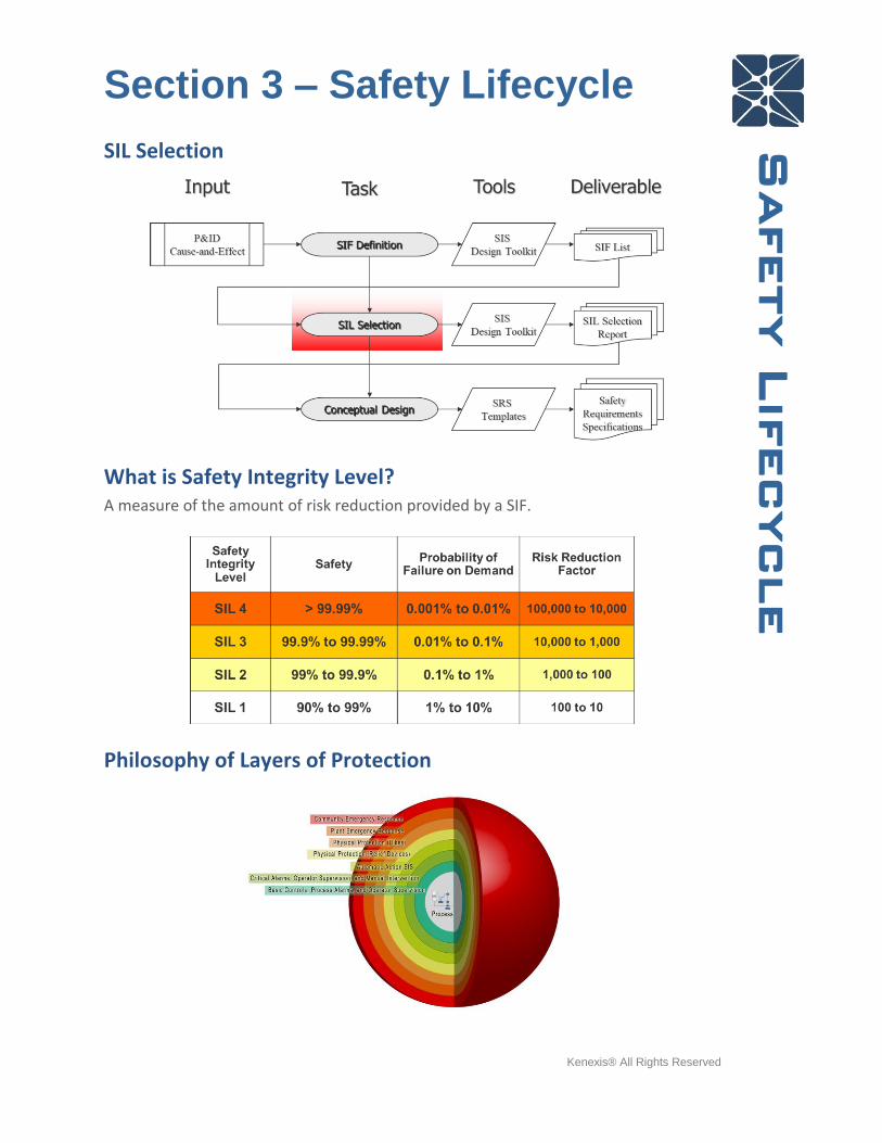
Philosophy of Layers of Protection .......................................................................... 26
SIS Risk Reduction .................................................................................................... 27
Model of Accident Causation ................................................................................... 27
Initiating Event Frequency ....................................................................................... 28
Requirements of an Independent Protection Layer ................................................ 28
Credit for Layers of Protection ................................................................................. 29
Risk Tolerance Criteria – Target Selection ............................................................... 29
LOPA Example – Distillation Column ....................................................................... 30
Risk Tolerance – Distillation Column ....................................................................... 30
LOPA Event Tree for Distillation Column ................................................................. 31
Conceptual Design ................................................................................................... 31
Conceptual Design Attributes .................................................................................. 32
Safety Requirements Specifications ........................................................................ 32
SRS General Requirements ...................................................................................... 32
SRS SIF Requirements .............................................................................................. 33
SRS Instrument Requirements ................................................................................. 34
Table of Contents
Kenexis® All Rights Reserved
SRS Logic Description ............................................................................................... 34
SIL Verification ......................................................................................................... 35
Reliability Models ..................................................................................................... 35
Parameters Impacting SIL / Risk Reduction ............................................................. 36
Component Selection............................................................................................... 36
Fault Tolerance ........................................................................................................ 36
Typical SIL 1 Architecture ......................................................................................... 37
Fault Tolerant Architecture – SIL 2/3 ....................................................................... 37
Functional Test Interval ........................................................................................... 38
Architectures – 1oo1 (one-out-of-one) ................................................................... 38
Architectures – 2oo3 (two-out-of-three) ................................................................. 39
Detailed Design ........................................................................................................ 39
Construction, Installation, and Commissioning ....................................................... 40
Site Acceptance Testing ........................................................................................... 40
Operation and Maintenance .................................................................................... 40
Management of Bypasses ........................................................................................ 41
Alternate Protection Plan ........................................................................................ 41
Bypass Risk Assessment ........................................................................................... 42
SIS Maintenance and Testing ................................................................................... 42
Management of Change .......................................................................................... 43
Post Instructional Quiz ................................................................................................. 44
Application Exercise #1 - Solution ................................................................................ 47
Option #1 – Do Nothing ........................................................................................... 47
Option #2 – Independent Alarm .............................................................................. 48
Option #3 – SIF with Shared Final Element.............................................................. 49
Option #4 – Complete Independent SIF – No Redundancy ..................................... 50
Option #5 – Complete Independent SIF – Sensor Redundancy ............................... 50
Option #6 – Complete SIF – Sensor and Valve Redundancy .................................... 51
Table of Contents
Kenexis® All Rights Reserved
Option #7 –Redundancy for Safety and Nuisance Trip Avoidance .......................... 51
Option #8 –Solenoid Valve Redundancy for Spurious Trip Avoidance .................... 52
Post Instructional Quiz Solution .................................................................................. 52

Section 0 – Scope and Roadmap
Kenexis® All Rights Reserved
Scope and roadmap
Safety instrumented systems (SIS) are one of the most flexible and common safeguards
used in the process industries to reduce risk to a tolerable level. This training course
will provide an overview and awareness level discussion of the topic, and is the starting
point for further learning on the topic.
Course Objectives The overall objective of this training course is to introduce the participant to the topic
of performance based design of safety instrumented systems as defined in the
international standard IEC 61511-2017: Functional Safety: Safety Instrumented Systems
for the Process Industry Sector. This is accomplished by addressing the following
points:
• Identify causes of accidents with SIS implications
• Understand philosophy of Layers of Protection
• Know steps in the Safety Lifecycle
• Understand Safety Integrity Levels (SIL) impact SIS Design
• Know what’s needed in a Safety Requirements Specification (SRS)
• Understand SIS Operation, Maintenance & Testing Requirements
Course Roadmap The training course is divided into the following sections:
• Section 1 Introduction / Overview
• Section 2 Selected Industry Incidents with SIS Implications
• Section 3 The Safety Lifecycle
Section 1 - Introduction
Kenexis® All Rights Reserved
Introduction
Section 1 - Introduction
What is an SIS? Informal Definition:
• Instrumented Control System that detects “out of control” conditions and
automatically returns the process to a safe state
“Last Line of Defense”
• Not basic process control system (BPCS)
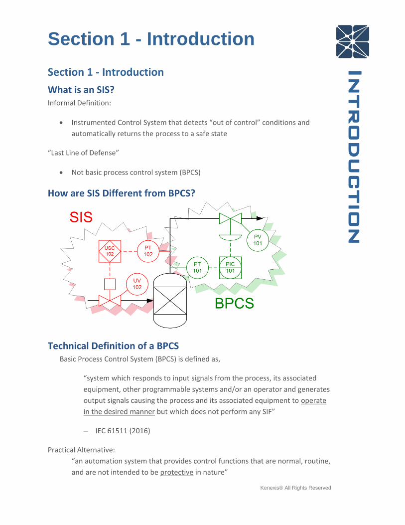
How are SIS Different from BPCS?
Technical Definition of a BPCS Basic Process Control System (BPCS) is defined as,
“system which responds to input signals from the process, its associated
equipment, other programmable systems and/or an operator and generates
output signals causing the process and its associated equipment to operate
in the desired manner but which does not perform any SIF”
– IEC 61511 (2016)
Practical Alternative:
“an automation system that provides control functions that are normal, routine,
and are not intended to be protective in nature”

Section 1 - Introduction
Kenexis® All Rights Reserved
Introduction
Technical Definition of SIS Safety Instrumented System (SIS) is defined as,
• “Instrumented system used to implement one or more SIFs."
Safety Instrumented Function (SIF) is defined as,
• "Safety function to be implemented by a safety instrumented system (SIS)"
Safety Function is defined as,
• “Function to be implemented by one or more protection layers which is
intended to achieve or maintain a safe state for the process, with respect to a
specific hazardous event." IEC 61511-1 (2016)
Practical Alternative: “Control System composed of sensors, logic solvers and final
control elements designed for the purpose of:
Automatically moving a process to a safe state when pre-defined safe operating
limits have been violated; “Preventative”
Permit a process to operate only when permissive safe operating conditions
have been proven; “Permissive”
Scope of the SIS

Section 1 - Introduction
Kenexis® All Rights Reserved
Introduction
Safety Instrumented Function - Definition “Safety function to be implemented by a Safety Instrumented System (SIS)”
IEC 61511-1 (2016)
• Alternative. A function be implemented by a SIS which is intended to achieve or
maintain a safe state for a process with respect to a specific hazardous event.
SIF Prevents a Specific Hazard
SIS is Protective in Nature Hypothesis: Most major accidents happen because a multiple failures occur; starting
with an initiating event
A well-engineered SIS stops the chain of events, but it is not intended to prevent an
initiating event from occurring.

Section 1 - Introduction
Kenexis® All Rights Reserved
Introduction
Hazards Protected by SIS Many common hazards are protected using safety instrumented systems. Some
common examples include:
• Hydrotreater Runaway Reaction (Refining)
• High Pressure Feed Pump Anti-Backflow
• Fired Heater Burner Management
• Coker Interlocks
• Tank Overfill Systems
Concern for SIS Design, Maintenance, and Operation Process Accidents are a reality and many are due to the lack of well-engineered
safeguards. Process Design increasingly relies on Automation Systems to ensure Safety
There is a potential for SIS failures that are:
• “hidden” (not self-revealing),
• “dangerous” (inhibiting)
In order to address this there are Industry Standards for SIS Design, Operation,
Maintenance, including:
• ANSI/ISA 84.01 - 1996
• IEC 61508, Published 1998
• IEC 61511, Published 2003

Section 1 - Introduction
Kenexis® All Rights Reserved
Introduction
Regulation and Standards • During Late 1980’s, industry safety performance deemed inadequate by
regulators worldwide
• Many national regulations were enacted which required implementation of
process safety programs (such as OSHA Process Safety Management rule in
the US)
• Regulations require RAGAGEP as design basis for safety-critical equipment
• “Recognized and Generally Accepted Good Engineering Practice”
• International Standards bodies such as IEC develop standards to clarify
RAGAGEP
Section 1 - Introduction
Kenexis® All Rights Reserved
Introduction
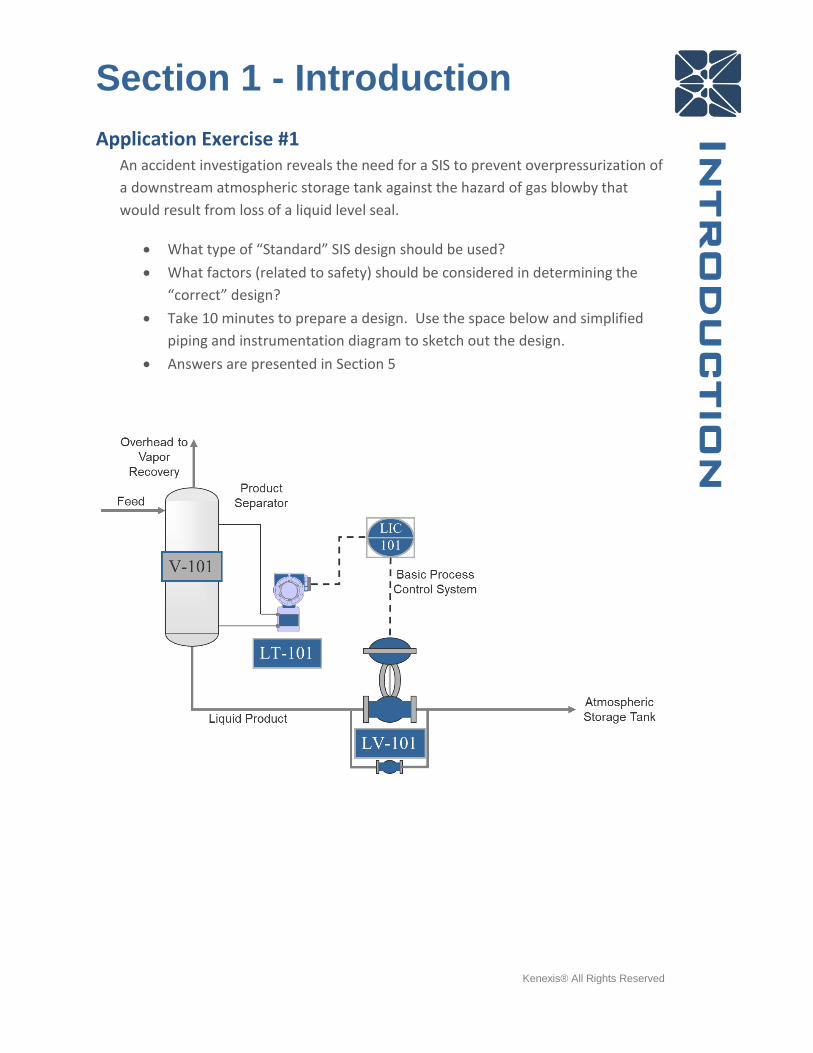
Application Exercise #1 An accident investigation reveals the need for a SIS to prevent overpressurization of
a downstream atmospheric storage tank against the hazard of gas blowby that
would result from loss of a liquid level seal.
• What type of “Standard” SIS design should be used?
• What factors (related to safety) should be considered in determining the
“correct” design?
• Take 10 minutes to prepare a design. Use the space below and simplified
piping and instrumentation diagram to sketch out the design.
• Answers are presented in Section 5
Section 1 - Introduction
Kenexis® All Rights Reserved
Introduction
What is a Standard SIS Design? In most cases, the prescriptive approach to SIS design is not optimal from the
standpoint of cost or safety…
Many design decisions depend on the specific application and the required level of
safety performance
• Equipment type
• Vendor
• Voting arrangement
• Test Intervals

Section 2 – Lessons Learned
Kenexis® All Rights Reserved
Lessons learned
Section 2 – Lessons Learned Section 2 presents a series of case studies where instrumentation and control failures
were key aspects of the accident scenarios and explains how the IEC 61511 standard
was written to address these root causes. Then, provides a worked practical example
of how the SIS safety lifecycle is implemented.
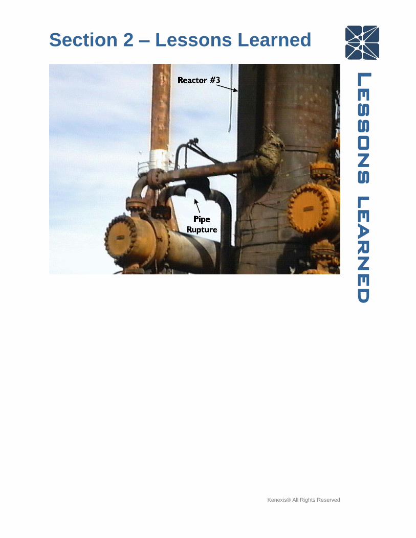
Case History 1: Automatic vs. Manual Action • Hydrocracker runaway reaction USA 1998
• Temperature excursion due to runaway reaction
• Operators failed to manually bring the process to a safe state (no manual de-
pressure)
• Temperature in the effluent pipe reached in excess of 1400 F
• 1 worker fatality; 46 injured
• Current design, automated shutdown

Section 2 – Lessons Learned
Kenexis® All Rights Reserved
Lessons learned
Case History 1: Failure and Loss of Containment Point
Section 2 – Lessons Learned
Kenexis® All Rights Reserved
Lessons learned
Section 2 – Lessons Learned
Kenexis® All Rights Reserved
Lessons learned
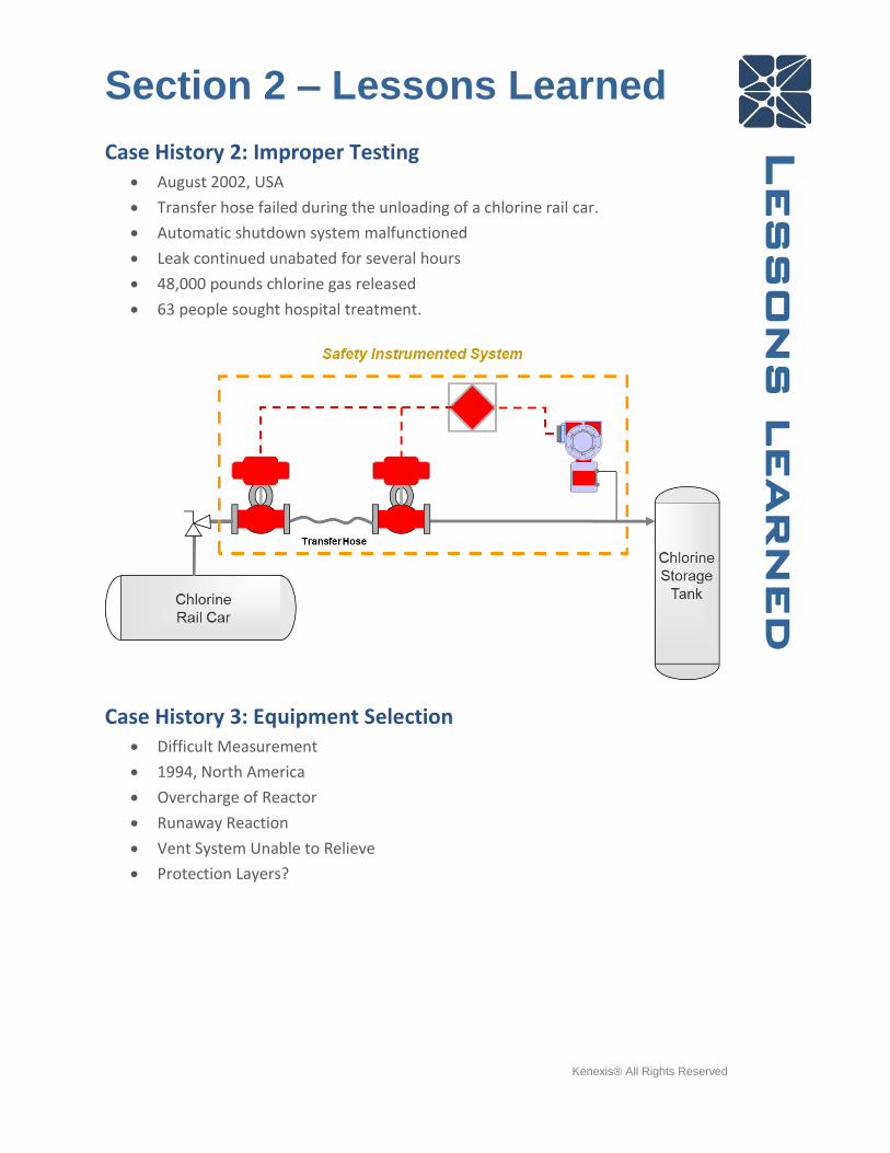
Case History 2: Improper Testing • August 2002, USA
• Transfer hose failed during the unloading of a chlorine rail car.
• Automatic shutdown system malfunctioned
• Leak continued unabated for several hours
• 48,000 pounds chlorine gas released
• 63 people sought hospital treatment.
Case History 3: Equipment Selection • Difficult Measurement
• 1994, North America
• Overcharge of Reactor
• Runaway Reaction
• Vent System Unable to Relieve
• Protection Layers?

Section 2 – Lessons Learned
Kenexis® All Rights Reserved
Lessons learned
Case History 4: Bypassing Safety functionality is frequently bypassed
• Difficulty in startup (Boiler Explosion, Asia 1990’s)
• Problematic instruments
• Confusing or complex operation
Accident Causal Factors • No SIS installed
• Poor basis for when safety should be automated
• Questionable equipment selection
• Redundancy and Diagnostics
• Testing methods poor
• Poor basis for testing frequency
• Improper bypassing equipment and techniques
Section 2 – Lessons Learned
Kenexis® All Rights Reserved
Lessons learned
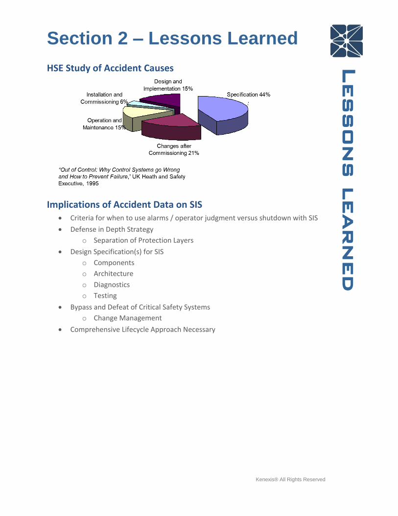
HSE Study of Accident Causes
Implications of Accident Data on SIS • Criteria for when to use alarms / operator judgment versus shutdown with SIS
• Defense in Depth Strategy
o Separation of Protection Layers
• Design Specification(s) for SIS
o Components
o Architecture
o Diagnostics
o Testing
• Bypass and Defeat of Critical Safety Systems
o Change Management
• Comprehensive Lifecycle Approach Necessary

Section 2 – Lessons Learned
Kenexis® All Rights Reserved
Lessons learned
Practical Example: High-Pressure Anti-Backflow
Layer of Protection Analysis

Section 2 – Lessons Learned
Kenexis® All Rights Reserved
Lessons learned
Anti-Backflow SIF: Proposed SIL 2 Design
Anti-Backflow SIF: Proposed SIL 2 Design Verification

Section 3 – Safety Lifecycle
Kenexis® All Rights Reserved
Safety Lifecycle
Section 3 – Safety Lifecycle This section discusses the SIS Safety Lifecycle as defined in the IEC 61511 standard.
This section also provides an overview of the SIS functional safety standard and the
regulations underpin their use and requirement. The section also includes a discussion
of the safety lifecycle phases and practical steps in their implementation.
Industry Standard for Safety Instrumented Systems (SIS) International Electrotechnical Commission (IEC), IEC 61511-2017, Functional Safety:
Safety Instrumented Systems for the Process Sector
Localized Versions:
• US - Instrumentation, Systems, and Automation Society (ISA), ANSI/ISA
S84.00.01-2004, Functional Safety: Safety Instrumented Systems for the Process
Industry Sector, 2004.
IEC 61511 Standard Safety Lifecycle Provide a complete safety lifecycle to address all root causes of failure
• Identification of systems
• Design
• Testing
• Maintenance
• Management of Change
What does IEC 61511 require? • Performance based
• Defines a “safety lifecycle”
• Requires selection of performance target for each SIF
• Requires the design each SIF to that target and quantitative verification of
target achievement
Section 3 – Safety Lifecycle
Kenexis® All Rights Reserved
Safety Lifecycle
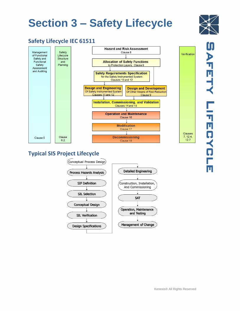
Safety Lifecycle IEC 61511
Typical SIS Project Lifecycle
Section 3 – Safety Lifecycle
Kenexis® All Rights Reserved
Safety Lifecycle
SIL Selection
What is Safety Integrity Level? A measure of the amount of risk reduction provided by a SIF.
Philosophy of Layers of Protection
Section 3 – Safety Lifecycle
Kenexis® All Rights Reserved
Safety Lifecycle
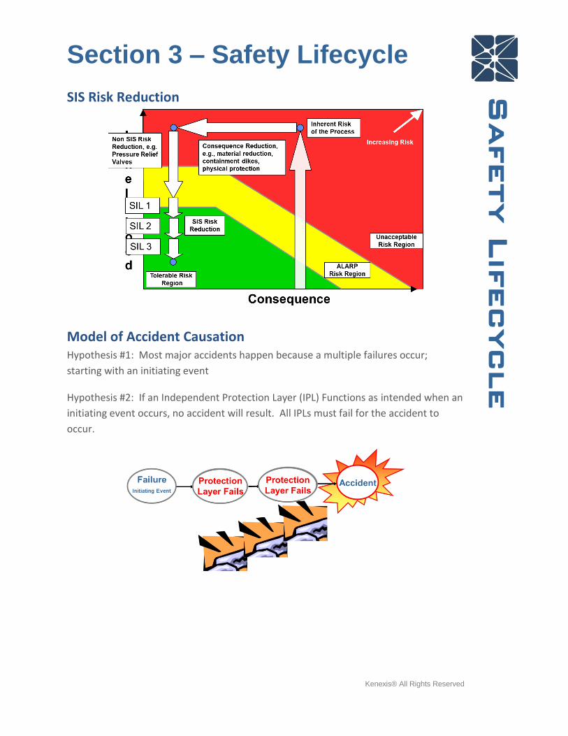
SIS Risk Reduction
Model of Accident Causation Hypothesis #1: Most major accidents happen because a multiple failures occur;
starting with an initiating event
Hypothesis #2: If an Independent Protection Layer (IPL) Functions as intended when an
initiating event occurs, no accident will result. All IPLs must fail for the accident to
occur.

Section 3 – Safety Lifecycle
Kenexis® All Rights Reserved
Safety Lifecycle
Initiating Event Frequency
Requirements of an Independent Protection Layer Independent Protection Layers (IPL) are limited to safeguards having the following
characteristics
• Specificity
o Specifically designed to prevent the Hazard Identified
• Independence
o From cause and other IPL
• Dependability
o One order of magnitude risk reduction
• Auditability
o Can be tracked / measured
What is not an IPL?
• PPE / Procedures / Preventive Maintenance / Inspection
Section 3 – Safety Lifecycle
Kenexis® All Rights Reserved
Safety Lifecycle
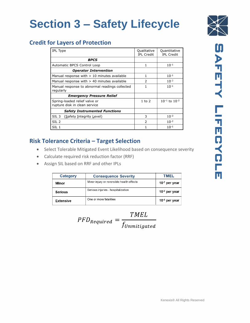
Credit for Layers of Protection
Risk Tolerance Criteria – Target Selection • Select Tolerable Mitigated Event Likelihood based on consequence severity
• Calculate required risk reduction factor (RRF)
• Assign SIL based on RRF and other IPLs

Section 3 – Safety Lifecycle
Kenexis® All Rights Reserved
Safety Lifecycle
LOPA Example – Distillation Column
Risk Tolerance – Distillation Column Overpressure could result in mechanical damage to column, release of flammable
hydrocarbon to atmosphere, potential fire/explosion hazard and potential fatality.
Section 3 – Safety Lifecycle
Kenexis® All Rights Reserved
Safety Lifecycle
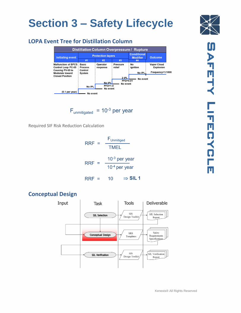
LOPA Event Tree for Distillation Column
Required SIF Risk Reduction Calculation
Conceptual Design
Section 3 – Safety Lifecycle
Kenexis® All Rights Reserved
Safety Lifecycle
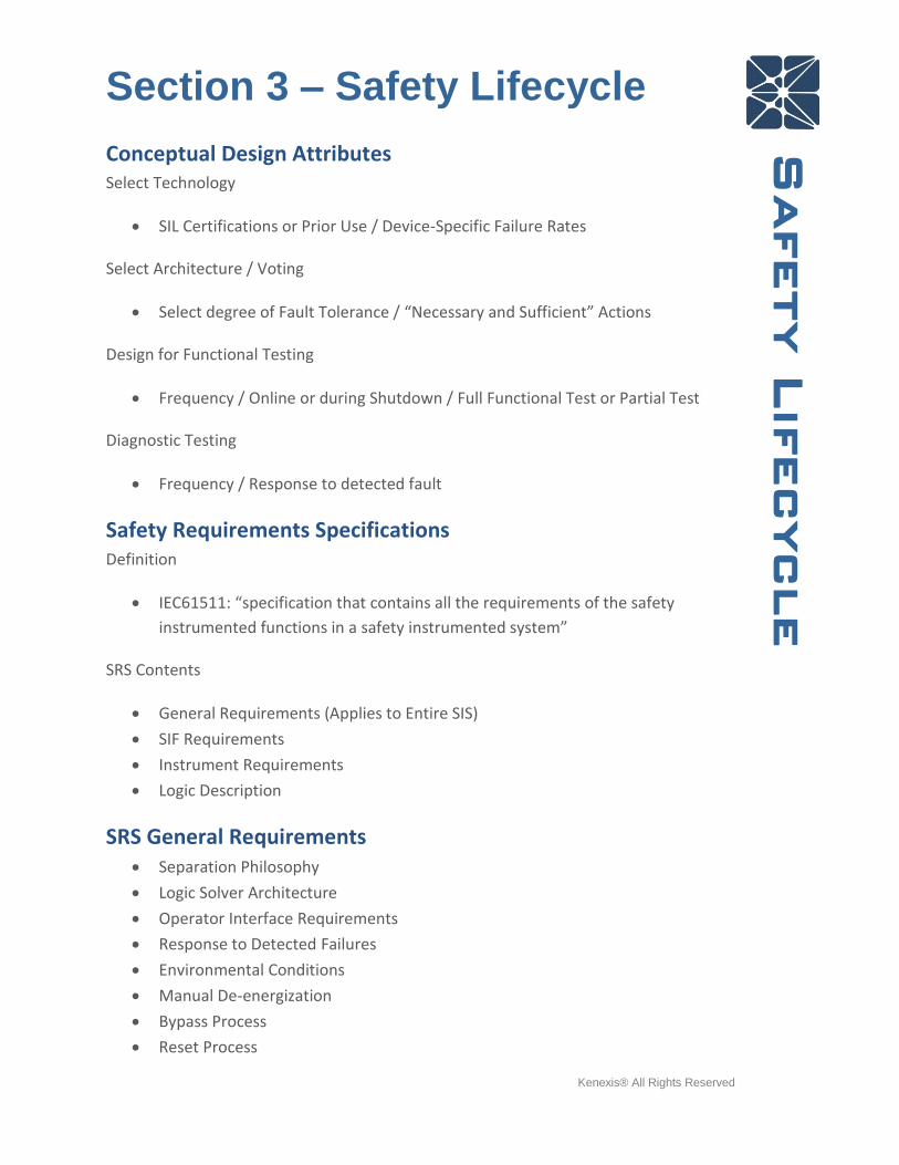
Conceptual Design Attributes Select Technology
• SIL Certifications or Prior Use / Device-Specific Failure Rates
Select Architecture / Voting
• Select degree of Fault Tolerance / “Necessary and Sufficient” Actions
Design for Functional Testing
• Frequency / Online or during Shutdown / Full Functional Test or Partial Test
Diagnostic Testing
• Frequency / Response to detected fault
Safety Requirements Specifications Definition
• IEC61511: “specification that contains all the requirements of the safety
instrumented functions in a safety instrumented system”
SRS Contents
• General Requirements (Applies to Entire SIS)
• SIF Requirements
• Instrument Requirements
• Logic Description
SRS General Requirements • Separation Philosophy
• Logic Solver Architecture
• Operator Interface Requirements
• Response to Detected Failures
• Environmental Conditions
• Manual De-energization
• Bypass Process
• Reset Process

Section 3 – Safety Lifecycle
Kenexis® All Rights Reserved
Safety Lifecycle
• Voting Degradation
SRS SIF Requirements • Demand Mode
• PHA/LOPA Reference
• Operating Modes
• Process Safety Time
• Achieved SIF Response Time

Section 3 – Safety Lifecycle
Kenexis® All Rights Reserved
Safety Lifecycle
SRS Instrument Requirements • Voting Arrangement
• Selection Basis
• Trip Settings
• Failure Responses
• Alarm Details
• Bypass Details
SRS Logic Description • Cause and Effect Diagram
• Inputs / Outputs
• Special Notes

Section 3 – Safety Lifecycle
Kenexis® All Rights Reserved
Safety Lifecycle
SIL Verification
Reliability Models
Section 3 – Safety Lifecycle
Kenexis® All Rights Reserved
Safety Lifecycle
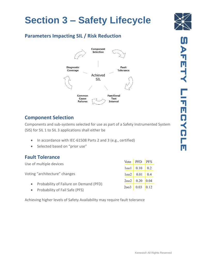
Parameters Impacting SIL / Risk Reduction
Component Selection Components and sub-systems selected for use as part of a Safety Instrumented System
(SIS) for SIL 1 to SIL 3 applications shall either be
• In accordance with IEC-61508 Parts 2 and 3 (e.g., certified)
• Selected based on “prior use”
Fault Tolerance Use of multiple devices
Voting “architecture” changes
• Probability of Failure on Demand (PFD)
• Probability of Fail Safe (PFS)
Achieving higher levels of Safety Availability may require fault tolerance
Section 3 – Safety Lifecycle
Kenexis® All Rights Reserved
Safety Lifecycle
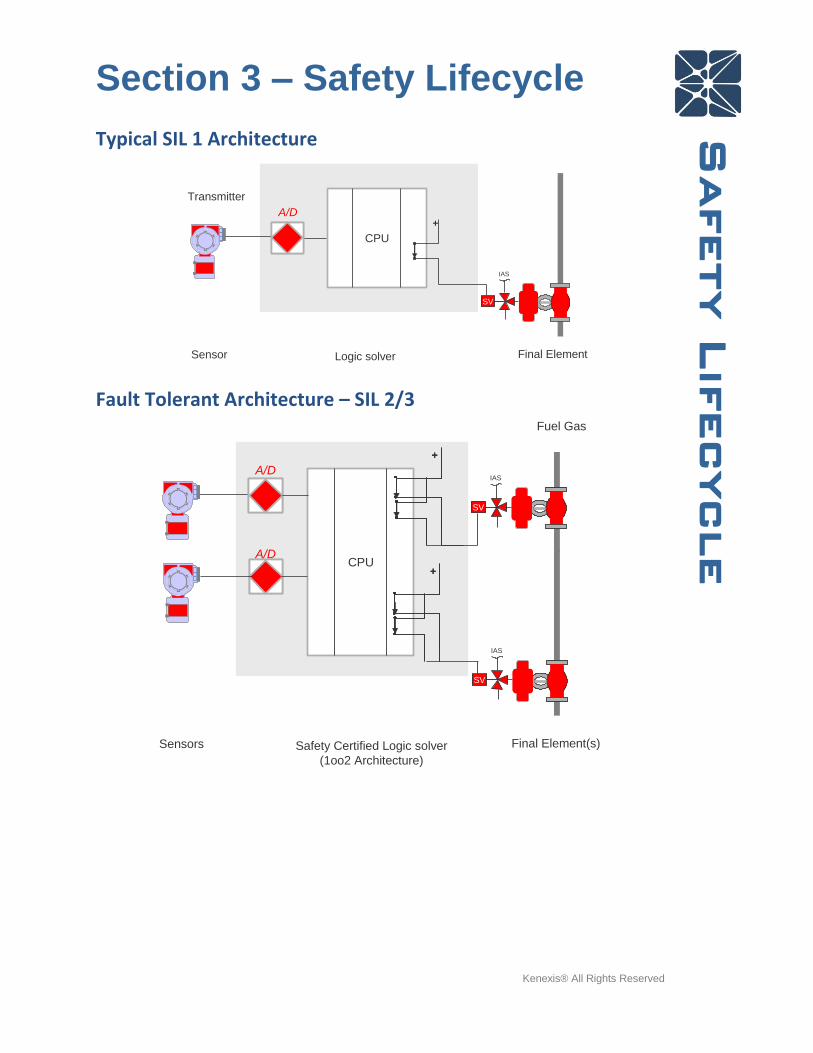
Typical SIL 1 Architecture
Fault Tolerant Architecture – SIL 2/3
CPU
Logic solver
Transmitter
Final Element
SV
IAS
+
Sensor
A/D
CPU
Safety Certified Logic solver
(1oo2 Architecture)
Final Element(s)
SV
SV
IAS
IAS
Fuel Gas
Sensors
++
++
A/D
A/D
Section 3 – Safety Lifecycle
Kenexis® All Rights Reserved
Safety Lifecycle
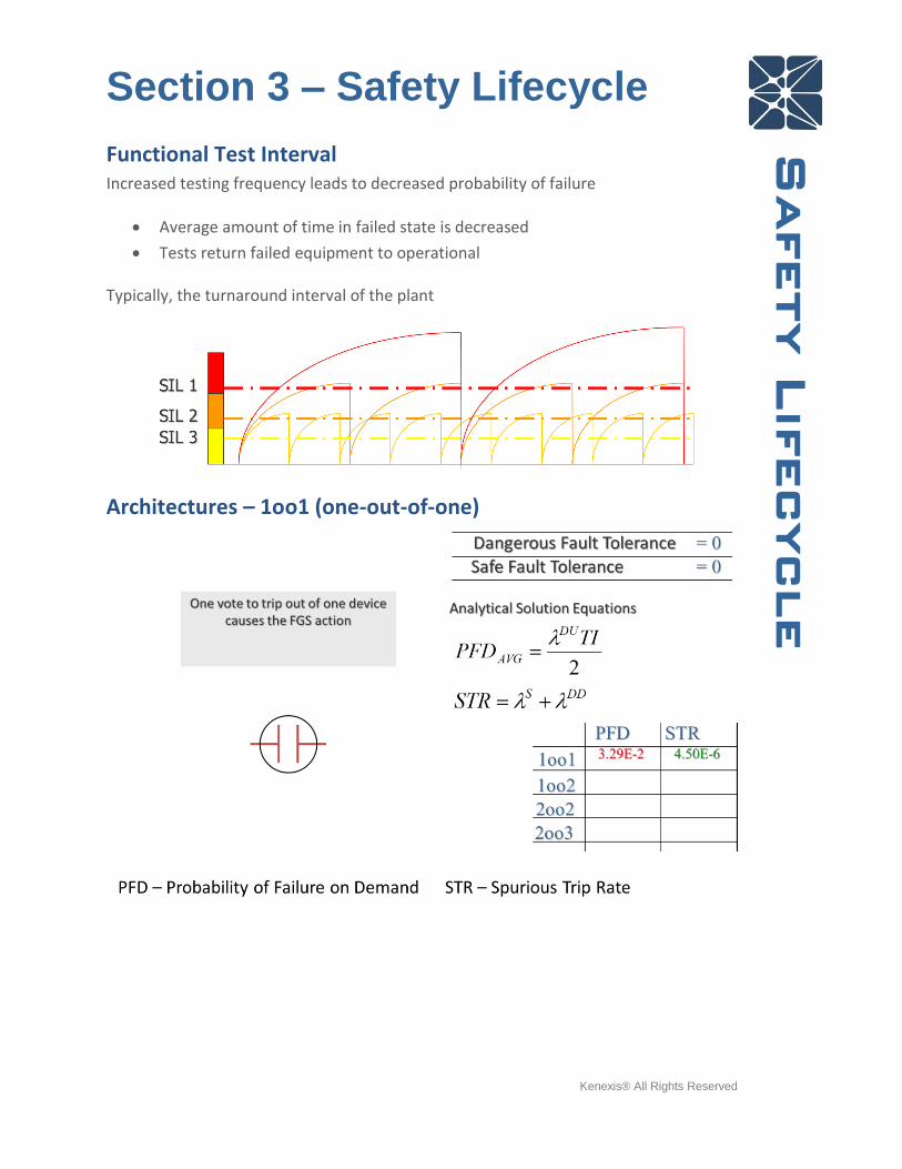
Functional Test Interval Increased testing frequency leads to decreased probability of failure
• Average amount of time in failed state is decreased
• Tests return failed equipment to operational
Typically, the turnaround interval of the plant
Architectures – 1oo1 (one-out-of-one)

Section 3 – Safety Lifecycle
Kenexis® All Rights Reserved
Safety Lifecycle
Architectures – 2oo3 (two-out-of-three)
Detailed Design • Loop Sheets
• Wiring Diagrams
• Cable Schedules
• PLC Programs
• System Integration
• SIS Operating Procedures (startup, reset, bypass, response to fault)
• SIS Maintenance and Testing Procedures
• Factory Acceptance Test (FAT)
Section 3 – Safety Lifecycle
Kenexis® All Rights Reserved
Safety Lifecycle
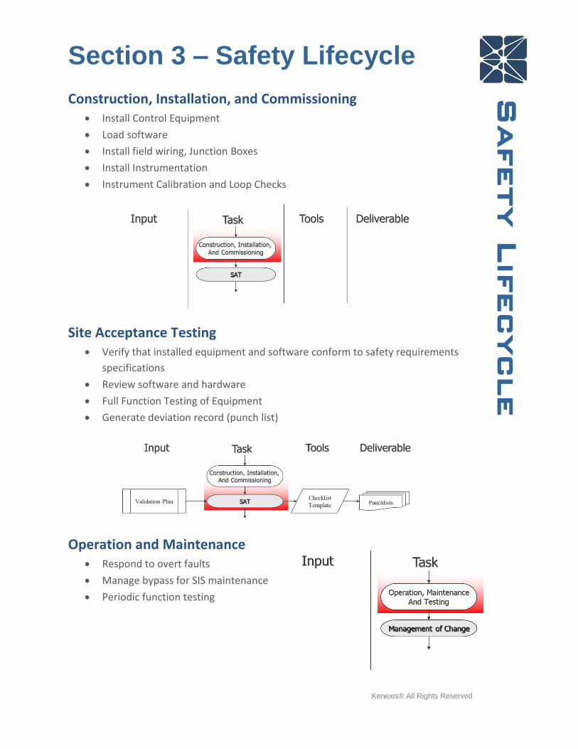
Construction, Installation, and Commissioning • Install Control Equipment
• Load software
• Install field wiring, Junction Boxes
• Install Instrumentation
• Instrument Calibration and Loop Checks
Site Acceptance Testing • Verify that installed equipment and software conform to safety requirements
specifications
• Review software and hardware
• Full Function Testing of Equipment
• Generate deviation record (punch list)
Operation and Maintenance • Respond to overt faults
• Manage bypass for SIS maintenance
• Periodic function testing

Section 3 – Safety Lifecycle
Kenexis® All Rights Reserved
Safety Lifecycle
Management of Bypasses Activation of any bypass should only be performed using a formal program
The formal program should include
• A procedure for authorizing and executing bypasses
o Development of Alternate Protection Plan, if required
o Bypass Risk Assessment, if required
• Mechanism for requiring appropriate approvals
• Auditing of bypass activations
• Restore to Operational within Assumed MTTR
Alternate Protection Plan • What process variables should be monitored?
• What are the manual trigger points?
• What personnel will perform the monitoring and manual shut down actions?
• What degree of independence from normal operation staff is required for
alternate protection plan staff?
Section 3 – Safety Lifecycle
Kenexis® All Rights Reserved
Safety Lifecycle
• What specific actions must be taken to manually shut down?
• Can a manual shutdown be performed within the process safety time?
Bypass Risk Assessment • Identify hazard prevented by bypassed SIF
• Identify consequence associated with the hazard
• Identify cumulative impact of addition of this bypass to any other existing
bypasses
• Identify initiating events during bypass that could result in the consequence and
ensure APP are capable of preventing the consequence
• Risk assessment performed by team including operations, engineering, HSE, and
equipment specialist
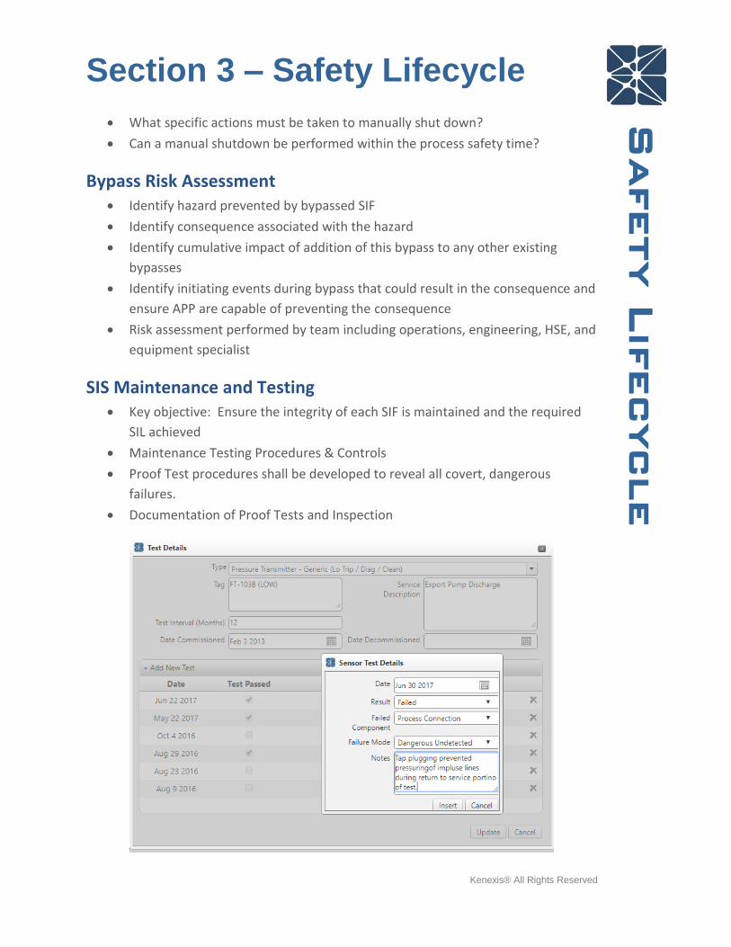
SIS Maintenance and Testing • Key objective: Ensure the integrity of each SIF is maintained and the required
SIL achieved
• Maintenance Testing Procedures & Controls
• Proof Test procedures shall be developed to reveal all covert, dangerous
failures.
• Documentation of Proof Tests and Inspection

Section 3 – Safety Lifecycle
Kenexis® All Rights Reserved
Safety Lifecycle
Management of Change Follow site Management of Change procedures…
Section 4 – Quiz
Kenexis® All Rights Reserved
Quiz
Post Instructional Quiz 1. Which of the following is the best definition of a Safety Instrumented System?
a. A control loop whose failure may result in the initiating of a chain of events
that could result in a hazardous outcome
b. Any instrumentation function that is related to process safety, such as a
critical alarm or a manually activated shutoff switch
c. A programmable logic controller that is dedicated to safety functionality
d. An instrumented control system that detects “out of control” conditions and
automatically returns the process to a safe state
2. Which of the following is the best definition of a safety instrumented function?
a. All the safety functionality contained in a safety instrumented system
b. A function that is implemented by an SIS that is intended to achieve or
maintain a safe state for a process with respect to a specific hazardous
event
c. A safety certified instrument
d. All basic process control loops whose failure could result in a safety
consequence
3. Most national regulations for process safety require which of the following as a
means to achieve functional safety of SIS?
a. Adherence to Recognized and Generally Accepted Good Engineering
Practice
b. Use of third party certified equipment and engineering resources
c. Development of prescriptive procedures by each individual operating
company with submittal of the procedures for licensure
d. Most regulations for process safety do not consider functional safety of SIS
4. Which of the following is a causal factor where poor SIS design resulted in, or
contributed to a process safety incident?
a. Improper isolation procedures were used to isolate pipe segments prior to
welding
b. Poor permitting procedures resulted in sources of ignition in an area where
flammable materials were stored
c. Poor basis for when safety should be automated as opposed to allowing
operator actions as the sole means of safeguarding
d. Failure to measure oxygen concentration before entry into a confined space.
5. In accordance to IEC 61511, how must verification that a safety integrity level
has been achieved by performed?
a. Qualitatively
b. Quantitatively

Section 4 – Quiz
Kenexis® All Rights Reserved
Quiz
c. Using third party certifications
d. Using standard design guidebooks
6. Which of the following activities, as defined in the IEC 61511 safety lifecycle,
occurs throughout the entire lifecycle of a SIS?
a. Hazard and Risk Assessment
b. Safety Requirements Specification
c. Operation and Maintenance
d. Management of Functional Safety and Functional Safety Assessment and
Auditing
7. Which range of average probability of failure on demand corresponds to SIL 1?
a. 1% to 10%
b. 0.1% to 1%
c. 0.01% to 0.1%
d. 0.001% to 0.01%
8. Which of the following is not an independent protection layer?
a. Preventive Maintenance
b. Operator Intervention Based on Alarms
c. Relief Valves
d. Check Valves
9. Which of the following is the best description of Target Maximum Event
Likelihood?
a. The maximum frequency at which an SIS should be activated
b. The maximum frequency of failure on non-SIS safeguards
c. The maximum frequency at which a control system failure can occur
d. The maximum frequency at which an event of a given consequence
magnitude is tolerable
10. Which of the following items can most appropriately be described in a safety
requirements specifications general note?
a. Process safety time for a SIF
b. Sensor measurement set point
c. Philosophy for separation of basic process control and safety control
d. Valves that are closed when a process switch indicates an out of control
condition
11. Which is the most common form of logic description in safety requirements
specifications?
a. Text Narrative
b. Cause-and-Effect Diagrams
c. Sequential Function Charts
d. Binary Logic Diagrams

Section 4 – Quiz
Kenexis® All Rights Reserved
Quiz
12. Achievement of higher SIL levels (2 and 3) often require some degree of
tolerance to dangerous failures which is provided by more advanced voting
schemes like 1oo2 or 2oo3 voting.
a. True
b. False
c. Not discussed in the IEC 61511 standard
d. Not application to safety instrumented systems
13. More frequent testing results in lower average probability of failure on demand
and higher achieved SIL because?
a. Better maintained instruments fail less frequently
b. The average amount of time that a device is in the failed state decreases
c. Improved auditing results in less scrutiny from regulatory agencies
d. When a device is bypassed in order to allow a test to occur it is not capable
of causing a spurious shutdown
14. If a SIS instrument is bypassed for any reason, and that device is the sole means
of bringing the process to a safe state if the SIF were to be activated by a
process loss-of-control (i.e., no redundancy), what documentation needs to be
prepared in order to allow the process to operate safely while the device is
bypassed?
a. Bypass Risk Assessment
b. Management of Change
c. Alternate Protection Plan
d. Bypass Authorization Form
15. What is the most critical attribute of a proof test of an SIS component?
a. Any known dangerous failure mode that is undetectable by automatic
diagnostics would be detected
b. The test is executed in the presence of the equipment vendor
c. The test procedure is provided by a SIL certified equipment vendor
d. The test uses automated tools that are connected to a computerized
maintenance management system (CMMS)
Section 5 – Application Exercise and Quiz Solutions
Kenexis® All Rights Reserved
Exercise/Q
uiz S
olutions
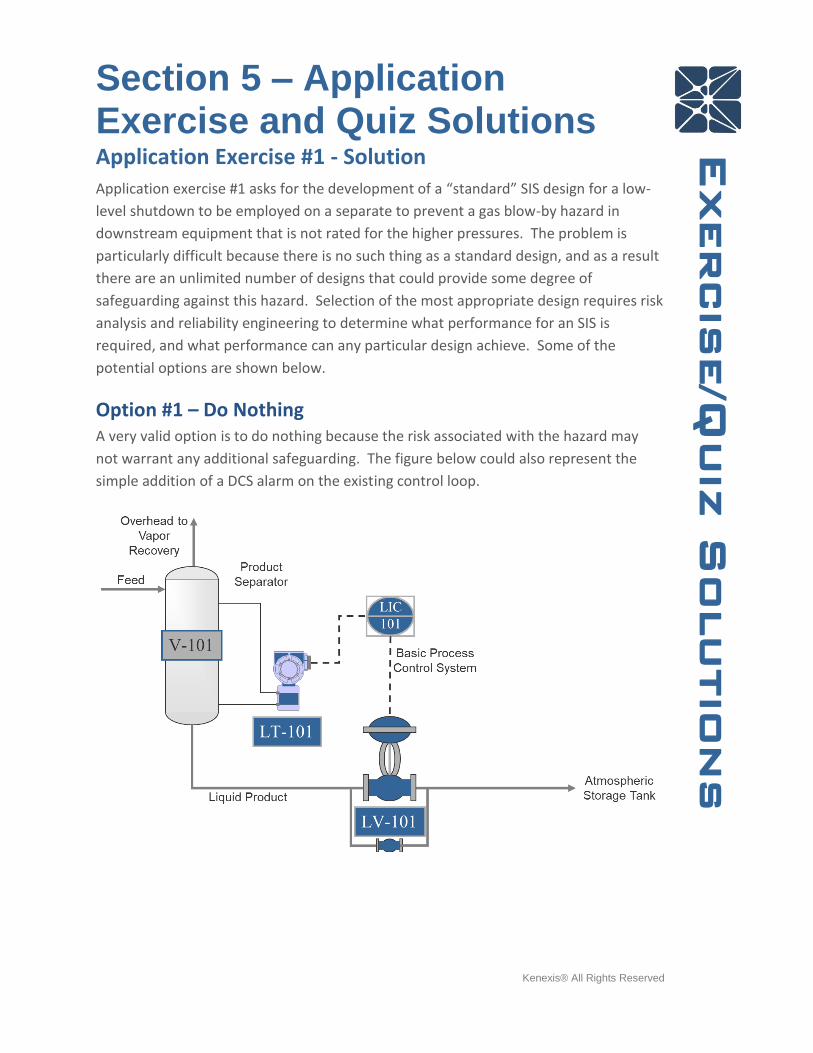
Application Exercise #1 - Solution Application exercise #1 asks for the development of a “standard” SIS design for a low-
level shutdown to be employed on a separate to prevent a gas blow-by hazard in
downstream equipment that is not rated for the higher pressures. The problem is
particularly difficult because there is no such thing as a standard design, and as a result
there are an unlimited number of designs that could provide some degree of
safeguarding against this hazard. Selection of the most appropriate design requires risk
analysis and reliability engineering to determine what performance for an SIS is
required, and what performance can any particular design achieve. Some of the
potential options are shown below.
Option #1 – Do Nothing A very valid option is to do nothing because the risk associated with the hazard may
not warrant any additional safeguarding. The figure below could also represent the
simple addition of a DCS alarm on the existing control loop.
Section 5 – Application Exercise and Quiz Solutions
Kenexis® All Rights Reserved
Exercise/Q
uiz S
olutions
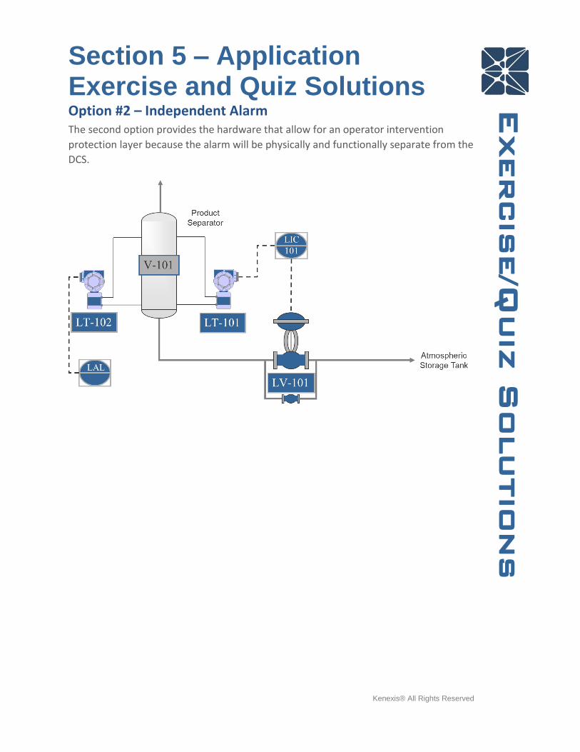
Option #2 – Independent Alarm The second option provides the hardware that allow for an operator intervention
protection layer because the alarm will be physically and functionally separate from the
DCS.
Section 5 – Application Exercise and Quiz Solutions
Kenexis® All Rights Reserved
Exercise/Q
uiz S
olutions
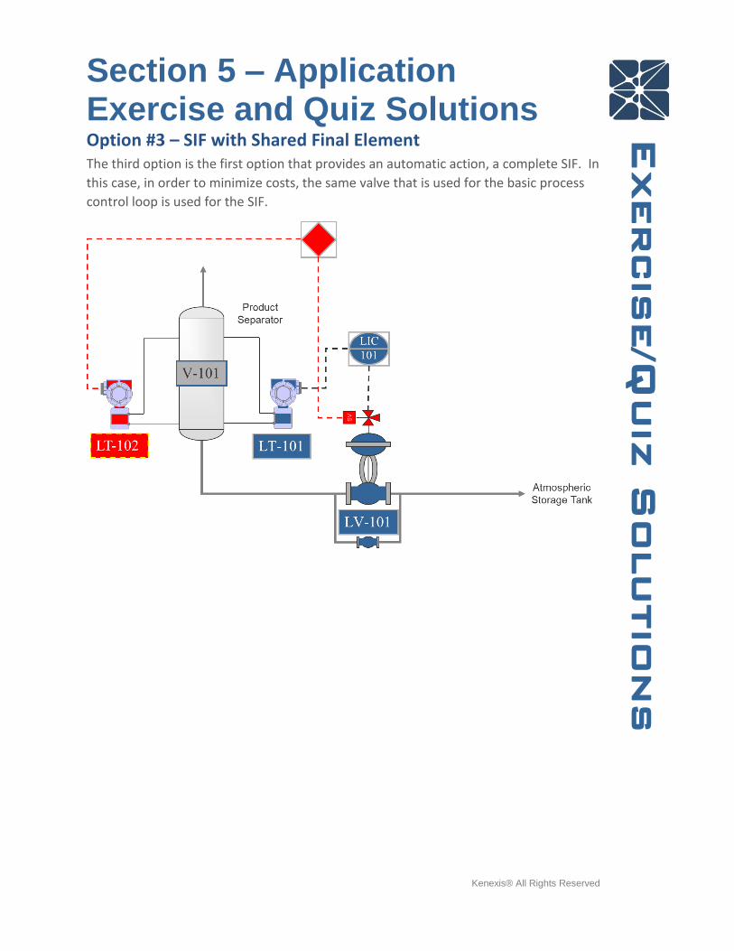
Option #3 – SIF with Shared Final Element The third option is the first option that provides an automatic action, a complete SIF. In
this case, in order to minimize costs, the same valve that is used for the basic process
control loop is used for the SIF.

Section 5 – Application Exercise and Quiz Solutions
Kenexis® All Rights Reserved
Exercise/Q
uiz S
olutions
Option #4 – Complete Independent SIF – No Redundancy Option #4 presents a complete SIF, but this SIF design includes no redundancy.
Option #5 – Complete Independent SIF – Sensor Redundancy Option #5 is a complete SIF that provides sensor redundancy to improve safety.
Section 5 – Application Exercise and Quiz Solutions
Kenexis® All Rights Reserved
Exercise/Q
uiz S
olutions
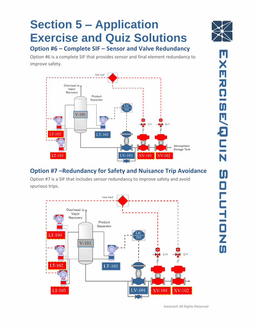
Option #6 – Complete SIF – Sensor and Valve Redundancy Option #6 is a complete SIF that provides sensor and final element redundancy to
improve safety.
Option #7 –Redundancy for Safety and Nuisance Trip Avoidance Option #7 is a SIF that includes sensor redundancy to improve safety and avoid
spurious trips.

Section 5 – Application Exercise and Quiz Solutions
Kenexis® All Rights Reserved
Exercise/Q
uiz S
olutions
Option #8 –Solenoid Valve Redundancy for Spurious Trip
Avoidance Option #8 extends Option #7 to include additional redundancy for the avoidance of
nuisance shutdowns of the final element subsystem.
All of the design presented above, and many more, could meet the objective of
reducing the risk posed by a low-level scenario. The most appropriate design,
however, is not standard, and can only be determined using performance based
methods such as the ones presented in the IEC 61511 standard.
Post Instructional Quiz Solution 1. Which of the following is the best definition of a Safety Instrumented System?
(d) An instrumented control system that detects “out of control” conditions and
automatically returns the process to a safe state
2. Which of the following is the best definition of a safety instrumented function?
(b) A function that is implemented by an SIS that is intended to achieve or
maintain a safe state for a process with respect to a specific hazardous event

Section 5 – Application Exercise and Quiz Solutions
Kenexis® All Rights Reserved
Exercise/Q
uiz S
olutions
3. Most national regulations for process safety require which of the following as a
means to achieve functional safety of SIS?
(a) Adherence to Recognized and Generally Accepted Good Engineering Practice
4. Which of the following is a causal factor where poor SIS design resulted in, or
contributed to a process safety incident?
(c) Poor basis for when safety should be automated as opposed to allowing
operator actions as the sole means of safeguarding
5. In accordance to IEC 61511, how must verification that a safety integrity level
has been achieved by performed?
(b) Quantitatively
6. Which of the following activities, as defined in the IEC 61511 safety lifecycle,
occurs throughout the entire lifecycle of a SIS?
(d) Management of Functional Safety and Functional Safety Assessment and
Auditing
7. Which range of average probability of failure on demand corresponds to SIL 1?
(a) 1% to 10%
8. Which of the following is not an independent protection layer?
(a) Preventive Maintenance
9. Which of the following is the best description of Target Maximum Event
Likelihood?
(d) The maximum frequency at which an event of a given consequence
magnitude is tolerable
10. Which of the following items can most appropriately be described in a safety
requirements specifications general note?
(c) Philosophy for separation of basic process control and safety control

Section 5 – Application Exercise and Quiz Solutions
Kenexis® All Rights Reserved
Exercise/Q
uiz S
olutions
11. Which is the most common form of logic description in safety requirements
specifications?
(b) Cause-and-Effect Diagrams
12. Achievement of higher SIL levels (2 and 3) often require some degree of
tolerance to dangerous failures which is provided by more advanced voting
schemes like 1oo2 or 2oo3 voting.
(a) True
13. More frequent testing results in lower average probability of failure on demand
and higher achieved SIL because?
(b) The average amount of time that a device is in the failed state decreases
14. If a SIS instrument is bypassed for any reason, and that device is the sole means
of bringing the process to a safe state if the SIF were to be activated by a
process loss-of-control (i.e., no redundancy), what documentation needs to be
prepared to allow the process to operate safely while the device is bypassed?
(c) Alternate Protection Plan
15. What is the most critical attribute of a proof test of an SIS component?
(a) Any known dangerous failure mode that is undetectable by automatic
diagnostics would be detected