Section-20 Safety Instrumented Systems
72
Haward Technology Middle East 1 Section 20 Process Control, Instrumentation and Safeguarding Section 20 Safety Instrumented Systems
-
Upload
alexander-ariza-nadjar -
Category
Documents
-
view
69 -
download
8
Transcript of Section-20 Safety Instrumented Systems
Haward Technology Middle East 1Section 20
Process Control, Instrumentation and Safeguarding
Section 20
Safety Instrumented Systems
Haward Technology Middle East 2Section 20
Process Control, Instrumentation and Safeguarding
Safety Instrumented Systems

Haward Technology Middle East 3Section 20
Process Control, Instrumentation and Safeguarding
TOPICS
Introduction
Probability of Failure
System Architecture
Safety PLC
Major Systems
Typical Questions & Answers
Safety Instrumented Systems
Haward Technology Middle East 4Section 20
Process Control, Instrumentation and Safeguarding
Introduction
Safety Instrumented Systems
Haward Technology Middle East 5Section 20
Process Control, Instrumentation and Safeguarding
INTRODUCTION
Safety Instrumented Systems
Haward Technology Middle East 6Section 20
Process Control, Instrumentation and Safeguarding
INTRODUCTION
“The prevention of accidents should not be considered a question of
legislation, but instead, our responsibility to fellow human beings
and common sense”
Werner von Siemens
Berlin, in the year of 1880
Safety Instrumented Systems
Haward Technology Middle East 7Section 20
Process Control, Instrumentation and Safeguarding
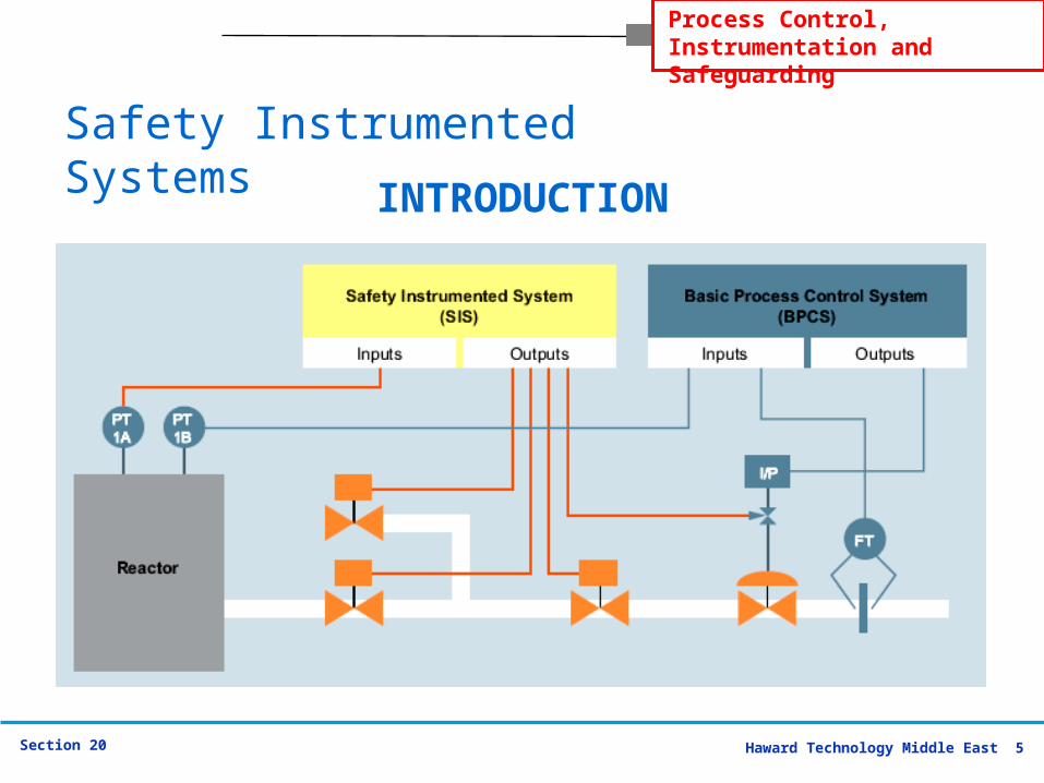
Safety instrumented systems (SIS) are used to provide safety control functions for processes, e.g. emergency shutdown (ESD), fire detection and blow-down functions.
SIS typically are composed of sensors, logic solvers and final control elements.
Due to the critical nature of such systems, OSHA recognizes compliance with the standard ANSI/ISA S84.01 - Application of Safety Instrumented System for the Process Industries - as a good engineering practice for safety instrumented systems.
INTRODUCTION
Safety Instrumented Systems
Haward Technology Middle East 8Section 20
Process Control, Instrumentation and Safeguarding
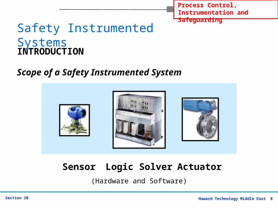
(Hardware and Software)
Logic solver
Sensor Logic Solver Actuator
Scope of a Safety Instrumented System
INTRODUCTION
Safety Instrumented Systems
Haward Technology Middle East 9Section 20
Process Control, Instrumentation and Safeguarding
Today SIS Safety Instrumented Systems play an increasingly important role in many process plants. Safety standards such as IEC 61508, IEC61511 as well as ISA S84.01, are creating more stringent safety requirements for process plants.
INTRODUCTION
Safety Instrumented Systems
Haward Technology Middle East 10Section 20
Process Control, Instrumentation and Safeguarding
Depending on application use, other names used for SIS Safety Instrumented Systems are:
Emergency Shutdown Systems (ESD), Burner Management Systems (BMS), Fire and Gas Systems (F&G), Critical Turbo-machinery Control, Railway Switching, Semiconductor Life Safety Systems (SEMI S2), Nuclear 1E Safety Systems, High Integrity Protection Systems (HIPS), High Integrity Pressure Protection System (HIPPS)
INTRODUCTION
Safety Instrumented Systems
Haward Technology Middle East 11Section 20
Process Control, Instrumentation and Safeguarding
The operation of many industrial processes involve inherent risks due to the presence of dangerous material like gases and chemicals.
Safety Instrumented Systems SIS are specifically designed to protect personnel, equipment and the environment by reducing the likelihood (frequency) or the impact severity of an identified emergency event.
INTRODUCTION
Safety Instrumented Systems
Haward Technology Middle East 12Section 20
Process Control, Instrumentation and Safeguarding
PROBABILITY of
FAILURE
Safety Instrumented Systems
Haward Technology Middle East 13Section 20
Process Control, Instrumentation and Safeguarding
PROBABILITY of FAILURE
By understanding how components of a Safety Instrumented System can fail, it is possible to calculate a Probability of Failure on Demand (PFD).
There are two basic ways for SIS to fail. The first way is commonly called a spurious trip which usually results in an unplanned but safe process shutdown.
While there is no danger associated with this type of SIS failure, the operational costs can be very high.
Safety Instrumented Systems
Haward Technology Middle East 14Section 20
Process Control, Instrumentation and Safeguarding
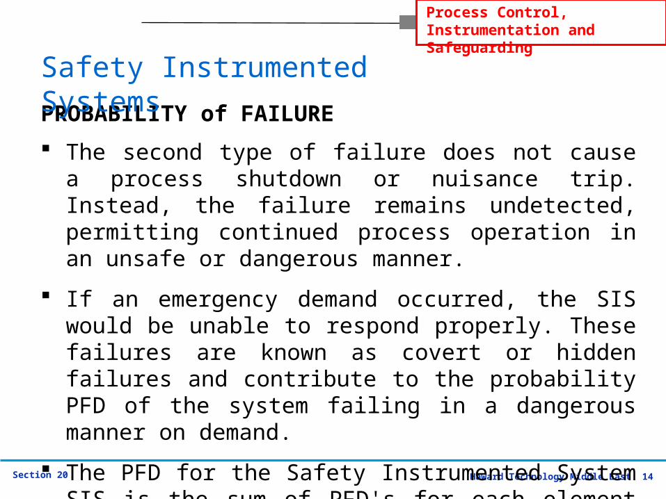
The second type of failure does not cause a process shutdown or nuisance trip. Instead, the failure remains undetected, permitting continued process operation in an unsafe or dangerous manner.
If an emergency demand occurred, the SIS would be unable to respond properly. These failures are known as covert or hidden failures and contribute to the probability PFD of the system failing in a dangerous manner on demand.
The PFD for the Safety Instrumented System SIS is the sum of PFD's for each element of the system.
PROBABILITY of FAILURE
Safety Instrumented Systems
Haward Technology Middle East 15Section 20
Process Control, Instrumentation and Safeguarding
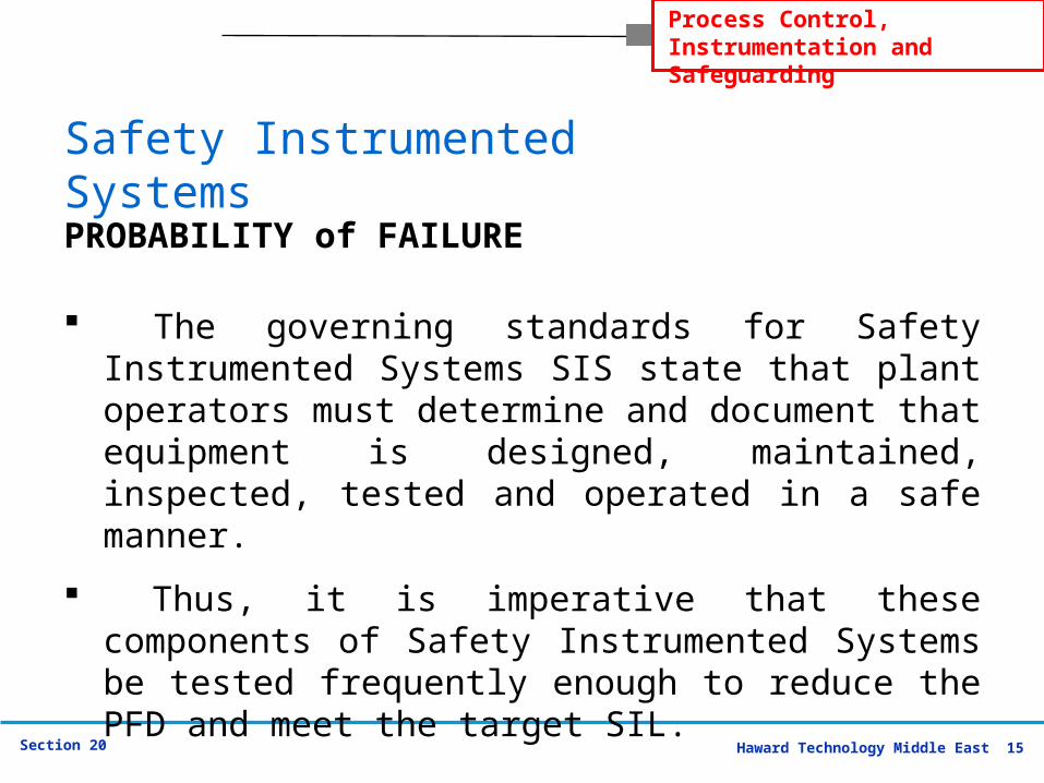
The governing standards for Safety Instrumented Systems SIS state that plant operators must determine and document that equipment is designed, maintained, inspected, tested and operated in a safe manner.
Thus, it is imperative that these components of Safety Instrumented Systems be tested frequently enough to reduce the PFD and meet the target SIL.
PROBABILITY of FAILURE
Safety Instrumented Systems
Haward Technology Middle East 16Section 20
Process Control, Instrumentation and Safeguarding
System Architecture
Safety Instrumented Systems
Haward Technology Middle East 17Section 20
Process Control, Instrumentation and Safeguarding
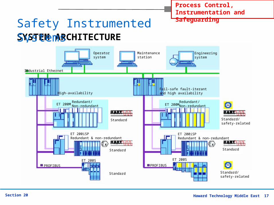
SYSTEM ARCHITECTURESafety Instrumented Systems
Operatorsystem
Maintenancestation
Engineeringsystem
Redundant/Non-redundant
Fail-safe fault-iterant and high availability
ET 200M
Standard/safety-related
Standard
Standard/safety-related
ET 200iSPRedundant & non-redundant
ET 200S
PROFIBUS
Industrial Ethernet
High-availability
Redundant/Non-redundantET 200M
ET 200iSPRedundant & non-redundant
ET 200S
PROFIBUS
Standard
Standard
Standard
Haward Technology Middle East 18Section 20
Process Control, Instrumentation and Safeguarding
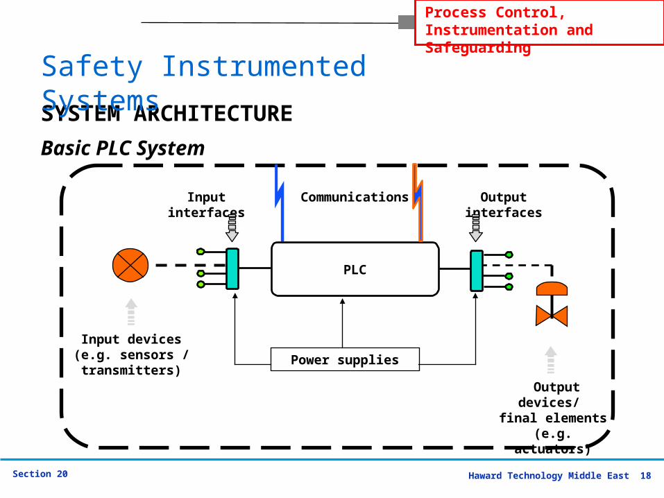
Basic PLC System
PLC
CommunicationsInput interfaces
Output interfaces
Output devices/ final elements
(e.g. actuators)
Input devices(e.g. sensors / transmitters)
Power supplies
SYSTEM ARCHITECTURE
Safety Instrumented Systems
Haward Technology Middle East 19Section 20
Process Control, Instrumentation and Safeguarding
Basic PLC System - Problems
Not designed for safety applications
Limited fail safe characteristics
High risk of covert failures (undetected dangerous failure modes) through lack of diagnostics.
Reliability of software (also stability of versions)
Flexibility without security
Unprotected communications
Limited redundancy
SYSTEM ARCHITECTURE
Safety Instrumented Systems
Haward Technology Middle East 20Section 20
Process Control, Instrumentation and Safeguarding
Upgrading of Standard PLCs for Safety Applications
Improvement Steps Improve Software QA Add hot back up Add I/O diagnostic circuits Install dual redundant system components
Problems Remain Reliability Analysis Cost and complexity Risk inherent in custom designs Documentation control Need for certification
SYSTEM ARCHITECTURE
Safety Instrumented Systems
Haward Technology Middle East 21Section 20
Process Control, Instrumentation and Safeguarding
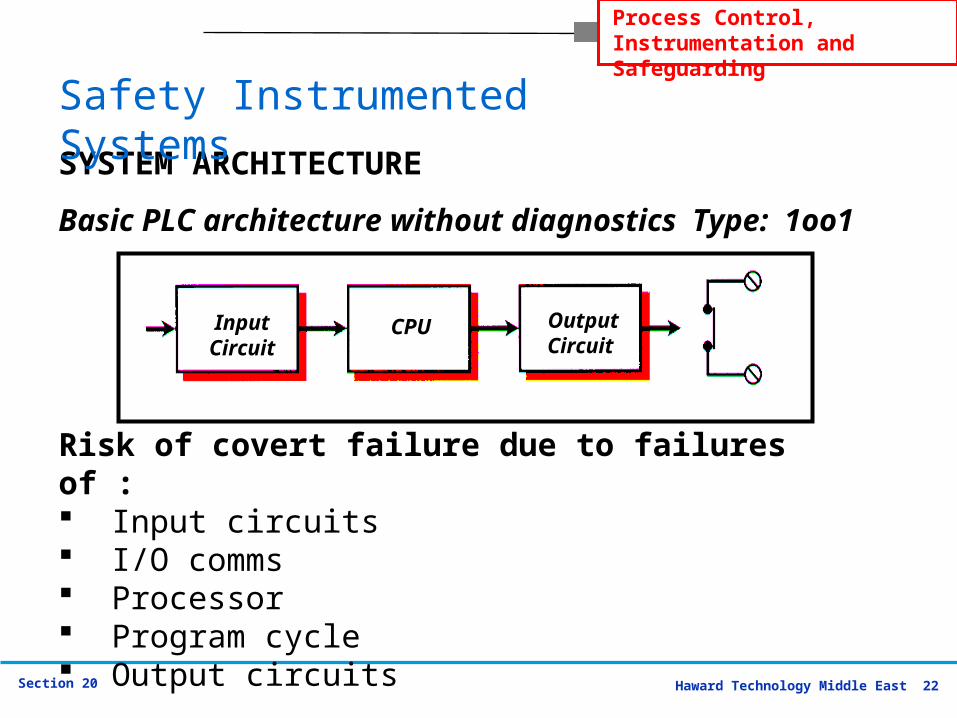
IEC 61508 / 61511 defines the following architectures:
1oo1
The architecture consists of a single channel for the safety function; any hazardous failure causes the failure of the safety function, if this is demanded.
SYSTEM ARCHITECTURE
Safety Instrumented Systems
Haward Technology Middle East 22Section 20
Process Control, Instrumentation and Safeguarding
Risk of covert failure due to failures of : Input circuits I/O comms Processor Program cycle Output circuits
Basic PLC architecture without diagnostics Type: 1oo1
Input Circuit
CPU OutputCircuit
SYSTEM ARCHITECTURE
Safety Instrumented Systems

Haward Technology Middle East 23Section 20
Process Control, Instrumentation and Safeguarding
Characteristics of Safety PLCs (1)
Automatic diagnostics continuously check the PLC system functions at short intervals within the fault tolerant time of the process.
>99% faults are notified for attention and repair. Redundant hardware options available to provide
uninterrupted operation even if one channel has failed.
On line hot replacement of failed modules can be provided.
All application software updated transparently to redundant channels.
SYSTEM ARCHITECTURE
Safety Instrumented Systems
Haward Technology Middle East 24Section 20
Process Control, Instrumentation and Safeguarding
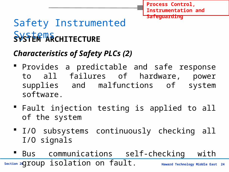
Characteristics of Safety PLCs (2)
Provides a predictable and safe response to all failures of hardware, power supplies and malfunctions of system software.
Fault injection testing is applied to all of the system
I/O subsystems continuously checking all I/O signals
Bus communications self-checking with group isolation on fault.
High security write protection on communication ports
SYSTEM ARCHITECTURE
Safety Instrumented Systems
Haward Technology Middle East 25Section 20
Process Control, Instrumentation and Safeguarding
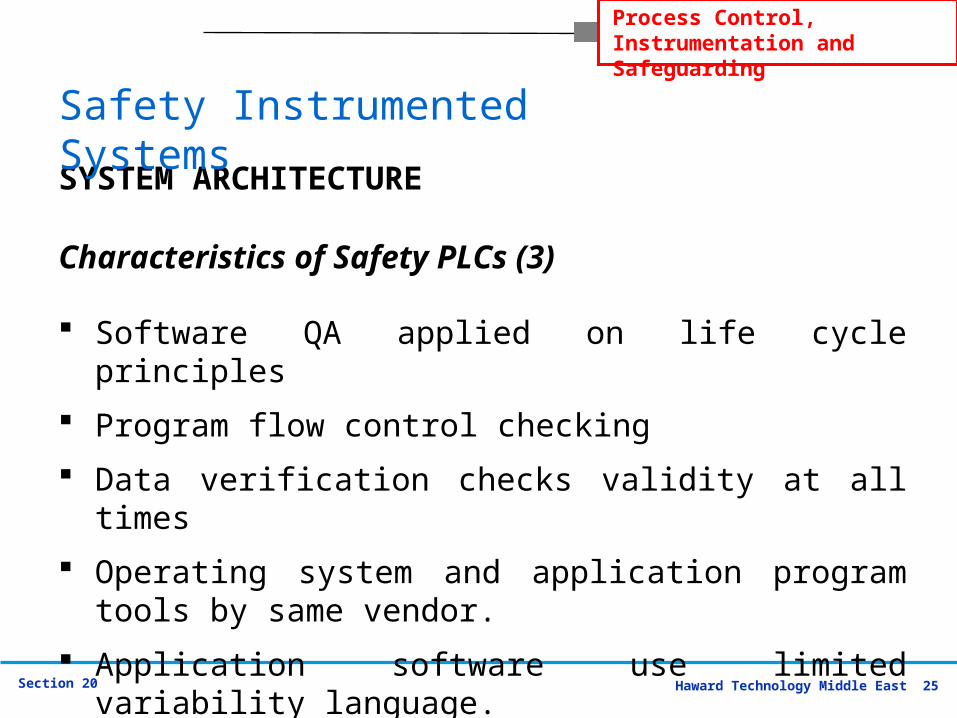
Characteristics of Safety PLCs (3)
Software QA applied on life cycle principles
Program flow control checking
Data verification checks validity at all times
Operating system and application program tools by same vendor.
Application software use limited variability language.
SYSTEM ARCHITECTURE
Safety Instrumented Systems
Haward Technology Middle East 26Section 20
Process Control, Instrumentation and Safeguarding
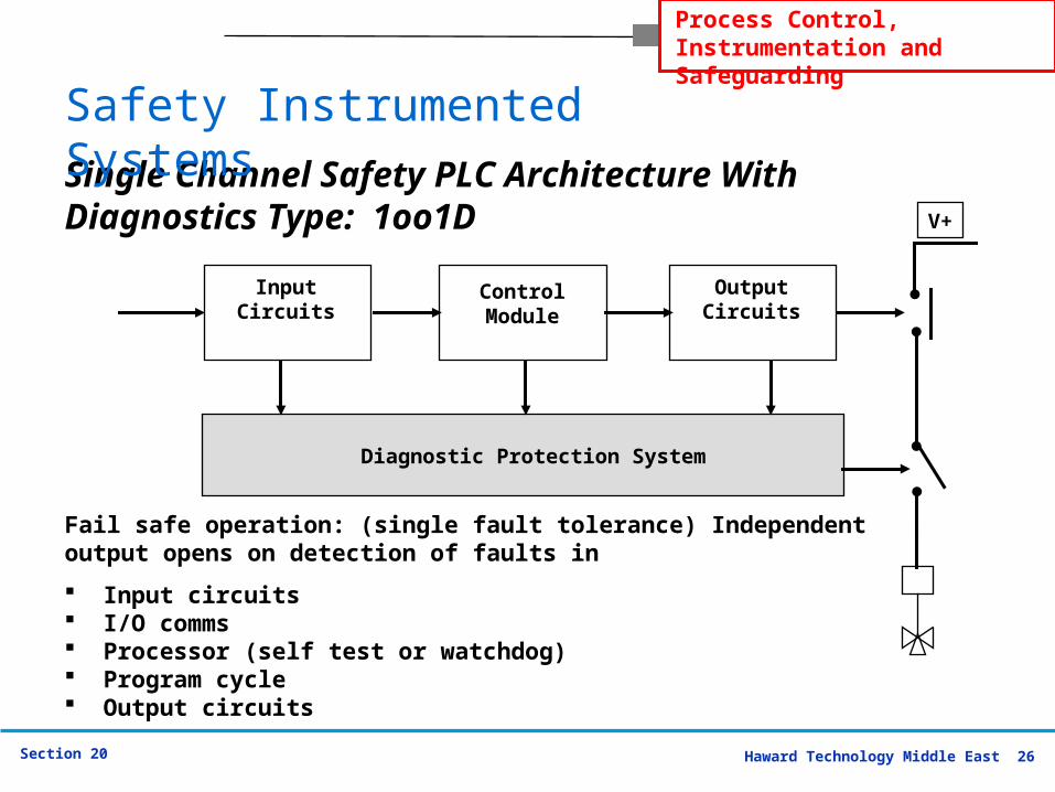
Single Channel Safety PLC Architecture With Diagnostics Type: 1oo1D
Fail safe operation: (single fault tolerance) Independent output opens on detection of faults in
Input circuits I/O comms Processor (self test or watchdog) Program cycle Output circuits
Input Circuits
Diagnostic Protection System
Control Module
Output Circuits
V+
Safety Instrumented Systems
Haward Technology Middle East 27Section 20
Process Control, Instrumentation and Safeguarding
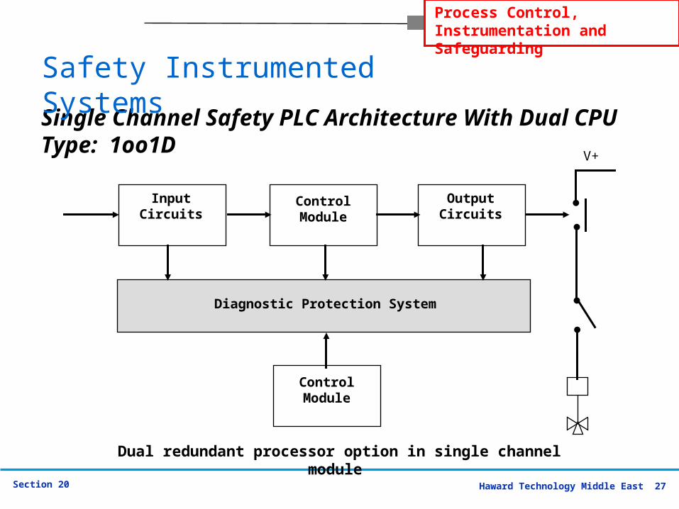
Dual redundant processor option in single channel module
Single Channel Safety PLC Architecture With Dual CPUType: 1oo1D
Input Circuits
Diagnostic Protection System
Control Module
Output Circuits
Control Module
V+
Safety Instrumented Systems
Haward Technology Middle East 28Section 20
Process Control, Instrumentation and Safeguarding
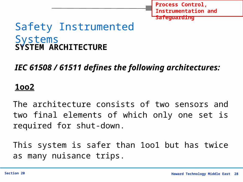
IEC 61508 / 61511 defines the following architectures:
1oo2The architecture consists of two sensors and two final elements of which only one set is required for shut-down.
This system is safer than 1oo1 but has twice as many nuisance trips.
SYSTEM ARCHITECTURE
Safety Instrumented Systems
Haward Technology Middle East 29Section 20
Process Control, Instrumentation and Safeguarding
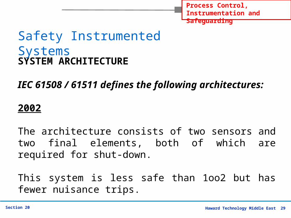
IEC 61508 / 61511 defines the following architectures:
2002
The architecture consists of two sensors and two final elements, both of which are required for shut-down.
This system is less safe than 1oo2 but has fewer nuisance trips.
SYSTEM ARCHITECTURE
Safety Instrumented Systems
Haward Technology Middle East 30Section 20
Process Control, Instrumentation and Safeguarding
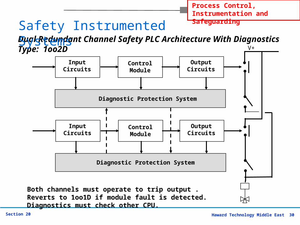
Input Circuits
Diagnostic Protection System
Control Module
Output Circuits
V+
Input Circuits
Diagnostic Protection System
Control Module
Output Circuits
Both channels must operate to trip output . Reverts to 1oo1D if module fault is detected. Diagnostics must check other CPU.
Dual Redundant Channel Safety PLC Architecture With DiagnosticsType: 1oo2D
Safety Instrumented Systems
Haward Technology Middle East 31Section 20
Process Control, Instrumentation and Safeguarding
Input Circuits
Diagnostic Protection System
Control Module
Output Circuits
V+
Input Circuits
Diagnostic Protection System
Control Module
Output Circuits
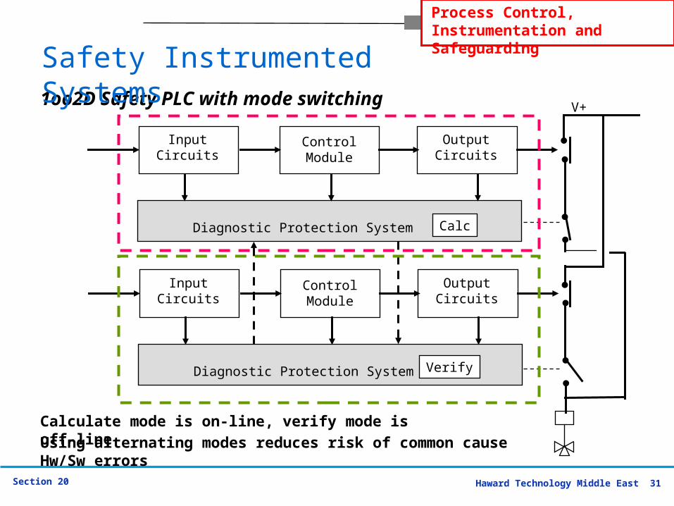
Calculate mode is on-line, verify mode is off-line
1oo2D Safety PLC with mode switching
Verify
Calc
Using alternating modes reduces risk of common cause Hw/Sw errors
Safety Instrumented Systems
Haward Technology Middle East 32Section 20
Process Control, Instrumentation and Safeguarding
Input Circuits
Diagnostic Protection System
Control Module
Output Circuits
V+
Input Circuits
Diagnostic Protection System
Control Module
Output Circuits
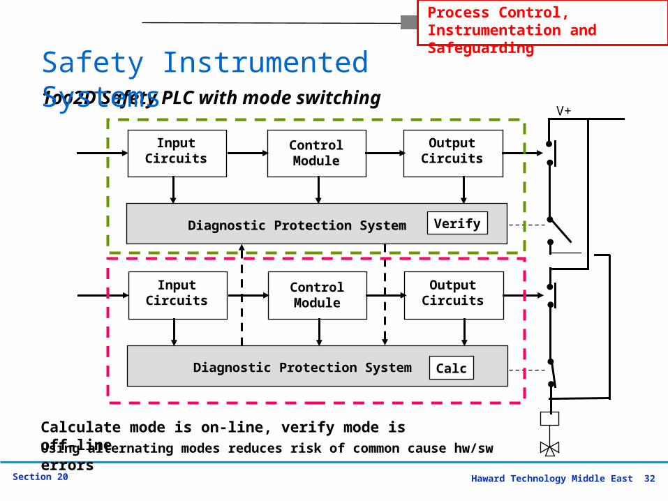
Calc
Verify
1oo2D Safety PLC with mode switching
Calculate mode is on-line, verify mode is off-lineUsing alternating modes reduces risk of common cause hw/sw errors
Safety Instrumented Systems
Haward Technology Middle East 33Section 20
Process Control, Instrumentation and Safeguarding
IEC 61508 / 61511 defines the following architectures:
2oo3
The architecture consists of three redundant channels that are connected with a majority output device. The output state does not change if the result of only one channel does not conform to the other two.
SYSTEM ARCHITECTURE
Safety Instrumented Systems
Haward Technology Middle East 34Section 20
Process Control, Instrumentation and Safeguarding
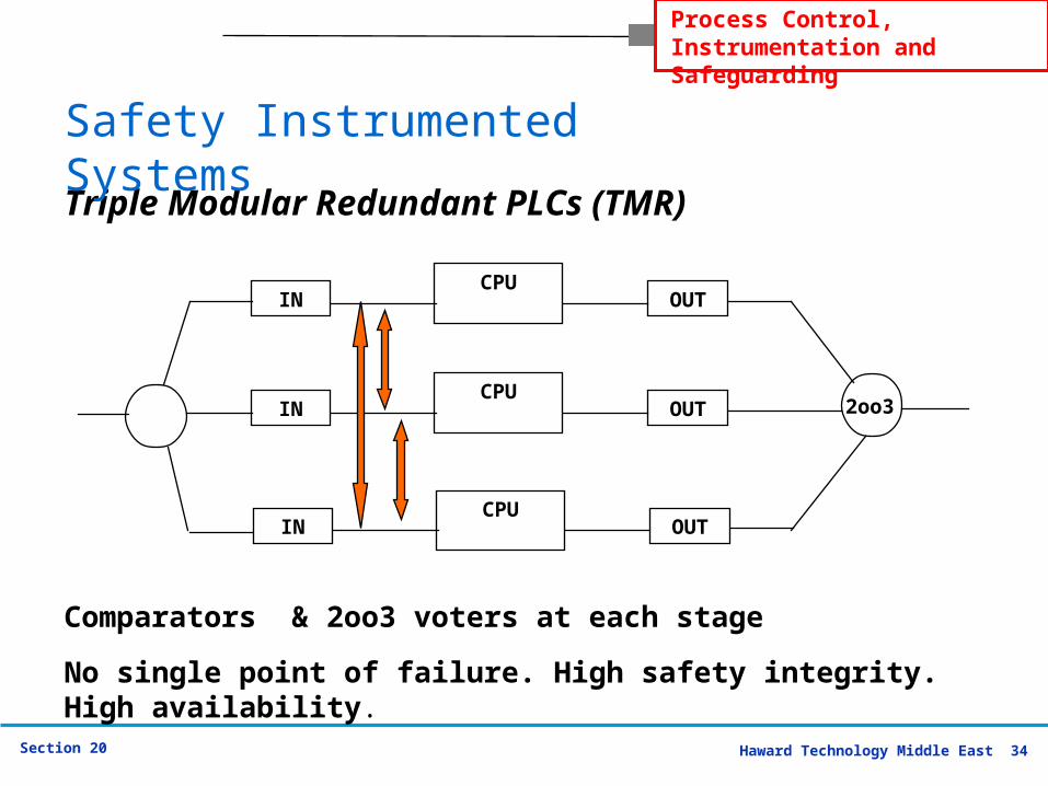
Triple Modular Redundant PLCs (TMR)
No single point of failure. High safety integrity. High availability.
INCPU
OUT
INCPU
OUT
INCPU
OUT
2oo3
Comparators & 2oo3 voters at each stage
Safety Instrumented Systems
Haward Technology Middle East 35Section 20
Process Control, Instrumentation and Safeguarding
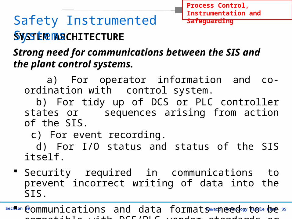
Strong need for communications between the SIS and
the plant control systems.
a) For operator information and co-ordination with control system.
b) For tidy up of DCS or PLC controller states or sequences arising from action of the SIS.
c) For event recording. d) For I/O status and status of the SIS itself.
Security required in communications to prevent incorrect writing of data into the SIS.
Communications and data formats need to be compatible with DCS/PLC vendor standards or open standards.
SYSTEM ARCHITECTURE
Safety Instrumented Systems
Haward Technology Middle East 36Section 20
Process Control, Instrumentation and Safeguarding
Safety Instrumented Systems
SAFETY PLC
Haward Technology Middle East 37Section 20
Process Control, Instrumentation and Safeguarding
Safety Instrumented Systems
This is a specially designed class of PLC which provides high reliability and high safety through the use of special electronic design, special software and pre-engineered redundancy.
The Safety PLC has I/O circuits which are designed to be fail-safe with built-in diagnostics.
SAFETY PLC

Haward Technology Middle East 38Section 20
Process Control, Instrumentation and Safeguarding
Safety Instrumented Systems
The processor of the Safety PLC has built in diagnostics for memory, processor operation, watchdog timer and all communications systems.
One-out-of-one with diagnostics (1oo1D) architecture uses specific diagnostic circuits to convert dangerous failures into safe failures by de-energising the output.
SAFETY PLC
Haward Technology Middle East 39Section 20
Process Control, Instrumentation and Safeguarding
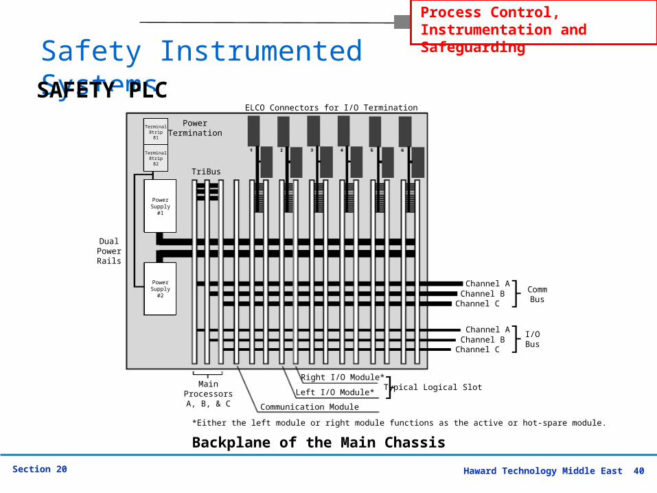
The TRICONEX system is designed with a fully triplicated architecture throughout, from the input modules through the Main Processors to the output modules.
Every I/O module houses the circuitry for three independent legs.
SAFETY PLC
Safety Instrumented Systems
Haward Technology Middle East 40Section 20
Process Control, Instrumentation and SafeguardingSafety Instrumented
SystemsELCO Connectors for I/O Termination
PowerTermination
TriBus
DualPowerRails
MainProcessorsA, B, & C
Right I/O Module*
Left I/O Module*
Communication Module
*Either the left module or right module functions as the active or hot-spare module.
Typical Logical Slot
Channel AChannel B
Channel C
Channel AChannel B
Channel C
CommBus
I/OBus
Backplane of the Main Chassis
Terminal8trip81
Terminal8trip82
PowerSupply
#1
PowerSupply
#2
SAFETY PLC
Haward Technology Middle East 41Section 20
Process Control, Instrumentation and Safeguarding
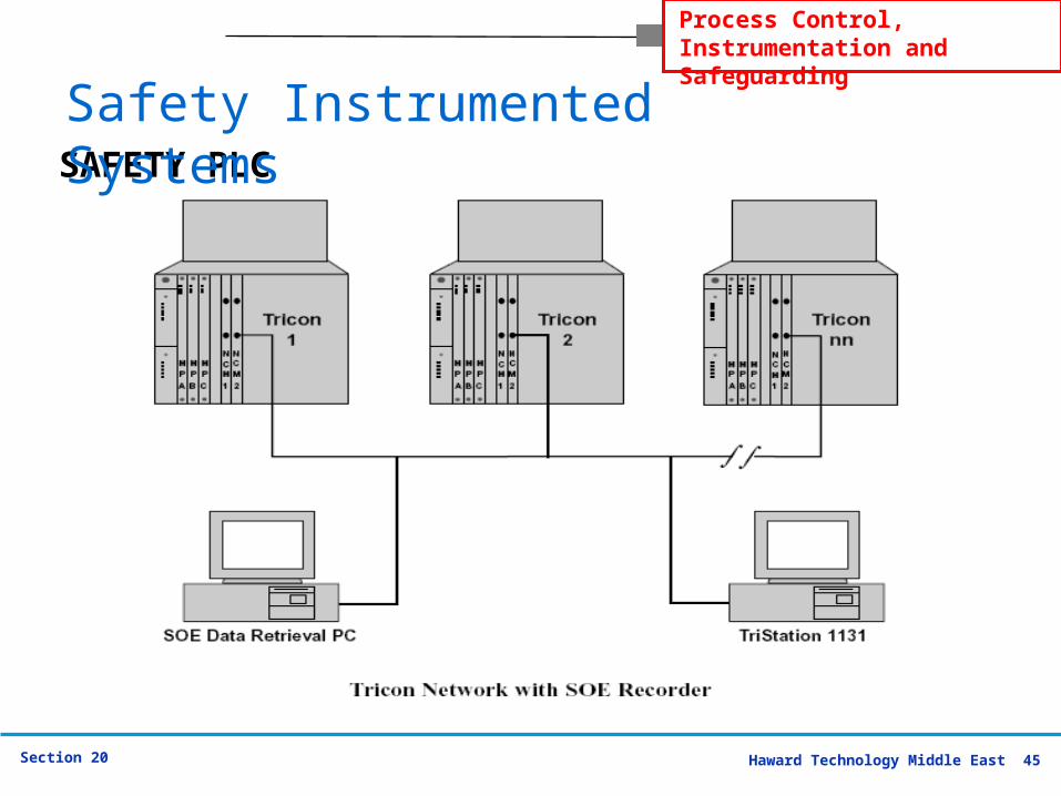
Each leg on the input modules reads the process data and passes that information to its respective Main Processor.
The three Main Processors communicate with each other using a proprietary high-speed bus system called the TriBus.
SAFETY PLC
Safety Instrumented Systems
Haward Technology Middle East 42Section 20
Process Control, Instrumentation and Safeguarding
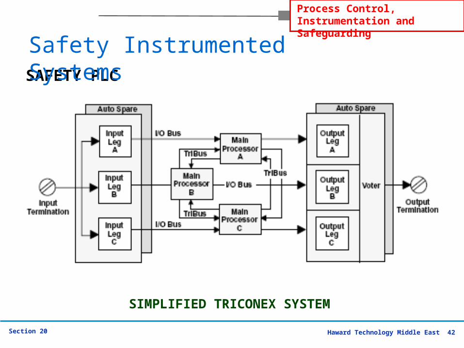
SIMPLIFIED TRICONEX SYSTEM
SAFETY PLC
Safety Instrumented Systems
Haward Technology Middle East 43Section 20
Process Control, Instrumentation and Safeguarding
The individual input table in each Main Processor is transferred to its neighbouring Main Processors over the proprietary TriBus.
During this transfer, hardware voting takes place.
The TriBus uses a Direct Memory Access programmable device to synchronize, transmit, vote and compare data among the three Main Processors.
SAFETY PLC
Safety Instrumented Systems
Haward Technology Middle East 44Section 20
Process Control, Instrumentation and Safeguarding
If a disagreement is discovered, the signal value found in two out of three tables prevails, and the third table is corrected accordingly.
One-time differences, which result from sample timing variations can be distinguished from a pattern of differing data.
The three independent Main Processors each maintain data about necessary corrections in local memory.
Any disparity is flagged and used at the end of the scan by the built-in Fault Analyser routines to determine whether a fault exists on a particular module.
SAFETY PLC
Safety Instrumented Systems
Haward Technology Middle East 45Section 20
Process Control, Instrumentation and Safeguarding
SAFETY PLC
Safety Instrumented Systems
Haward Technology Middle East 46Section 20
Process Control, Instrumentation and Safeguarding
Major Systems
Safety Instrumented Systems
Haward Technology Middle East 47Section 20
Process Control, Instrumentation and Safeguarding
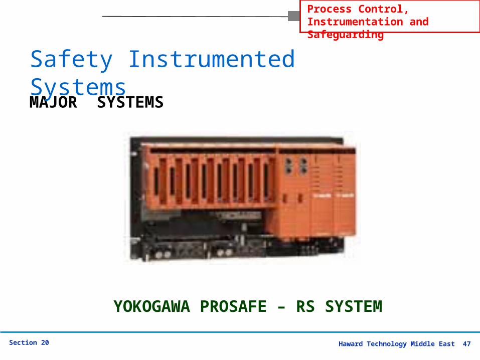
MAJOR SYSTEMS
YOKOGAWA PROSAFE – RS SYSTEM
Safety Instrumented Systems
Haward Technology Middle East 48Section 20
Process Control, Instrumentation and Safeguarding
Yokogawa / ProSafe-RS Achieving absolute integrity between distributed
control systems (DCS) and safety instrumented systems (SIS) for plant automation has traditionally raised complex design and integration issues.
Conventionally, two separate monitoring and operating environments were required for a DCS and SIS. Different communications and distinctive hardware architectures had to be set up.
MAJOR SYSTEMS
Safety Instrumented Systems
Haward Technology Middle East 49Section 20
Process Control, Instrumentation and Safeguarding
Yokogawa / ProSafe-RS
Plant managers striving to optimize process operations have taken it as a given that project time and expenses would escalate.
Now Yokogawa puts an end to DCS-SIS incompatibility with the new ProSafe-RS, the world’s first truly integrated "safety PLC" for the process industries.
MAJOR SYSTEMS
Safety Instrumented Systems
Haward Technology Middle East 50Section 20
Process Control, Instrumentation and Safeguarding
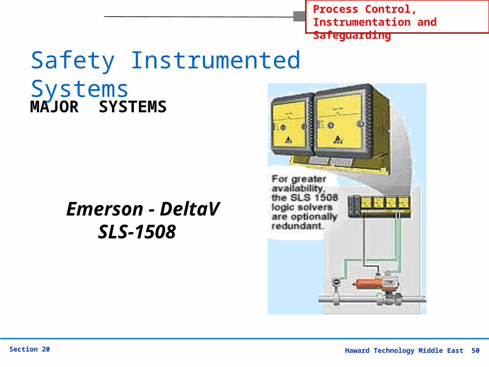
Emerson - DeltaV SLS-
1508
MAJOR SYSTEMS
Safety Instrumented Systems
Haward Technology Middle East 51Section 20
Process Control, Instrumentation and Safeguarding
Emerson Process Management / DeltaV SLS-1508
Emerson extends the proven innovations of their PlantWeb® architecture to safety applications.
The resulting smart safety instrumented system provides an integrated approach to complete safety loops - from sensor to logic solver to final control element.
It also uses digital intelligence and diagnostics to enable more automated safety loop testing and other features that increase system availability while reducing life-cycle costs and easing regulatory compliance.
MAJOR SYSTEMS
Safety Instrumented Systems
Haward Technology Middle East 52Section 20
Process Control, Instrumentation and Safeguarding
Emerson Process Management / DeltaV SLS-1508
As a key component of this smart SIS solution, the DeltaV SIS system takes advantage of the PlantWeb architecture's digital communications and smart diagnostics within field devices to increase the availability of the whole of the Safety Instrumented Function.
Scheduled partial-stroke testing of final control elements can improve the safety level, reduce the number of risky personnel trips into the field, and increase the mandatory proof test interval.
MAJOR SYSTEMS
Safety Instrumented Systems
Haward Technology Middle East 53Section 20
Process Control, Instrumentation and Safeguarding
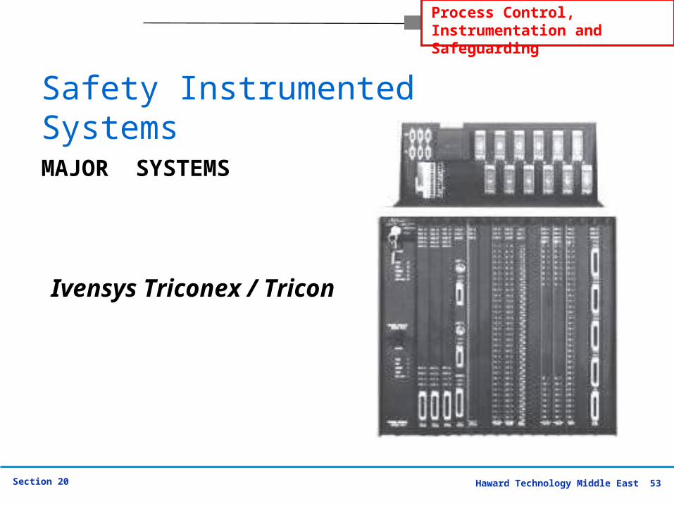
Ivensys Triconex / Tricon
MAJOR SYSTEMS
Safety Instrumented Systems
Haward Technology Middle East 54Section 20
Process Control, Instrumentation and Safeguarding
Ivensys Triconex / Tricon
The TRICON is a state-of-the-art fault tolerant controller based on a Triple-Modular Redundant (TMR) architecture. TMR employs three isolated, parallel control systems and extensive diagnostics integrated into one system. The system uses two-out-of-three voting to provide high integrity, error-free, uninterrupted process operation with no single point of failure.
MAJOR SYSTEMS
Safety Instrumented Systems
Haward Technology Middle East 55Section 20
Process Control, Instrumentation and Safeguarding
Ivensys Triconex / Tricon
Setting up applications is simplified with the TRICON, because the triplicated TMR system operates as a single control system from the user's point of view.
The extensive diagnostics are inherent and transparent to the programmer. All diagnostic information is stored in system variables and annunciated with Light Emitting Diode (LED) indicators.
MAJOR SYSTEMS
Safety Instrumented Systems
Haward Technology Middle East 56Section 20
Process Control, Instrumentation and Safeguarding
Ivensys Triconex / Tricon The Tricon controller can interface with Modbus
masters and slaves, Distributed Control Systems (DCS), external host computers on Ethernet networks and other Tricon systems on a Peer-to-Peer network.
The TriStation 1131 Developer's Workbench is an integrated tool for developing, testing, and documenting safety and critical process control applications for the Tricon and Trident programmable logic controllers. The programming methodology, user interface, and self-documentation capabilities make the system superior to traditional and competing engineering tools.
MAJOR SYSTEMSSafety Instrumented Systems
Haward Technology Middle East 57Section 20
Process Control, Instrumentation and Safeguarding
TYPICAL QUESTIONS &
ANSWERS
Safety Instrumented Systems
Haward Technology Middle East 58Section 20
Process Control, Instrumentation and Safeguarding
TYPICAL Q & A
1.What is a SIS?
A SIS is a Safety Instrumented System. It is designed to prevent or mitigate hazardous events by taking the process to a safe state when predetermined conditions are violated.
A SIS is composed of a combination of logic solver(s), sensor(s), and final element(s). Other common terms for SISs are safety interlock systems, emergency shutdown systems (ESD), and safety shutdown systems (SSD). A SIS can be one or more Safety Instrumented Functions (SIF).
Safety Instrumented Systems
Haward Technology Middle East 59Section 20
Process Control, Instrumentation and Safeguarding
2. What is a SIF?
SIF stands for Safety Instrumented Function.
A SIF is designed to prevent or mitigate a hazardous event by taking a process to a tolerable risk level. A SIF is composed of a combination of logic solver(s), sensor(s), and final element(s).
A SIF has an assigned SIL level depending on the amount of risk that needs to be reduced.
One or more SIFs comprise a SIS.
TYPICAL Q & A
Safety Instrumented Systems
Haward Technology Middle East 60Section 20
Process Control, Instrumentation and Safeguarding
3. What is SIL?
SIL stands for Safety Integrity Level.
A SIL is a measure of safety system performance, or probability of failure on demand (PFD) for a SIF or SIS.
There are four discrete integrity levels associated with SIL.
The higher the SIL level, the lower the probability of failure on demand for the safety system and the better the system performance.
TYPICAL Q & A
Safety Instrumented Systems
Haward Technology Middle East 61Section 20
Process Control, Instrumentation and Safeguarding
3. What is SIL?
It is important to also note that as the SIL level increases, typically the cost and complexity of the system also increase.
A SIL level applies to an entire system.
Individual products or components do not have SIL ratings.
SIL levels are used when implementing a SIF that must reduce an existing intolerable process risk level to a tolerable risk range.
TYPICAL Q & A
Safety Instrumented Systems
Haward Technology Middle East 62Section 20
Process Control, Instrumentation and Safeguarding
4. What does functional safety mean?
Functional safety is a term used to describe the safety system that is dependent on the correct functioning of the logic solver, sensors, and final elements to achieve the desired risk reduction level.
Functional safety is achieved when every SIF is successfully carried out and the process risk is reduced to the desired level.
TYPICAL Q & A
Safety Instrumented Systems
Haward Technology Middle East 63Section 20
Process Control, Instrumentation and Safeguarding
5. Why were the ANSI/ISA 84, IEC 61508, and IEC 61511
standards developed?
The standards were a natural evolution for the need to reduce process risk and improve safety through a more formalized and quantifiable methodology.
Additionally, and specifically for IEC 61508, as the application and usage of software has evolved and proliferated, there was an increased need to develop a standard to guide system / product designers and developers in what they needed to do to ensure and “claim” that their systems / products were acceptably safe for their intended uses.
TYPICAL Q & A
Safety Instrumented Systems
Haward Technology Middle East 64Section 20
Process Control, Instrumentation and Safeguarding
6. When do I need a SIF or a SIS?
The philosophy of the standards suggests that a SIS or SIF should be implemented only if there is no other non-instrumented way of adequately eliminating or mitigating process risk.
Specifically, the ANSI/ISA-84.00.01-2004 (IEC 61511 Mod) recommends a multi-disciplined team approach that follows the Safety Lifecycle, conducts a process hazard analysis, designs a variety of layers of protection, and finally implements a SIS when a hazardous event cannot be prevented or mitigated with something other than instrumentation.
TYPICAL Q & A
Safety Instrumented Systems
Haward Technology Middle East 65Section 20
Process Control, Instrumentation and Safeguarding
7. What is a proof-test interval?
Proof testing is a requirement of safety instrumented systems to ensure that everything is working and performing as expected.
Testing must include the verification of the entire system, logic solver, sensors, and final elements.
The testing frequency varies for each SIS and is dependent on the technology, system architecture, and target SIL level. The proof-test interval is an important component of the probability of failure on demand calculation for the system.
TYPICAL Q & A
Safety Instrumented Systems
Haward Technology Middle East 66Section 20
Process Control, Instrumentation and Safeguarding
8. What is a Process Hazard Analysis (PHA) and who conducts this?
A PHA is an OSHA directive that identifies safety problems and risks within a process, develops corrective actions to respond to safety issues, and preplans alternative emergency actions if safety systems fail.
The PHA must be conducted by a diverse team that has specific expertise in the process being analyzed. There are many consulting and engineering firms that also provide PHA services. PHA methodologies can include a What-If Analysis, Hazard and Operability Study (HAZOP), Failure Mode and Effects Analysis (FEMA), and a Fault Tree Analysis.
TYPICAL Q & A
Safety Instrumented Systems
Haward Technology Middle East 67Section 20
Process Control, Instrumentation and Safeguarding
9. What voting configurations are required for each SIL level?
Obtaining a desired SIL level is dependent on a multitude of factors. The type of technology employed, the number of system components, the probability of failure on demand (PFD) numbers for each component, the system architecture (e.g., redundancy, voting), and the proof testing intervals all play a significant role in the determination of a SIL level.
There is not a standard answer for what voting configurations are required for each SIL level. The voting architecture must be analyzed in the context of all the factors noted above.
TYPICAL Q & A
Safety Instrumented Systems
Haward Technology Middle East 68Section 20
Process Control, Instrumentation and Safeguarding
10.Will a SIL rated system require increased maintenance?
SIL solutions are certainly not always the most cost-effective solutions for decreasing process risk. Many times, implementing a SIL solution will require increased equipment, which inevitably will require increased maintenance.
Additionally, it is likely that the higher the SIL level, the more frequent the proof testing interval will be, which may ultimately increase the amount of system maintenance that is required. This is why the standards recommend a SIL based solution only when process risk cannot be reduced by other methods.
TYPICAL Q & A
Safety Instrumented Systems
Haward Technology Middle East 69Section 20
Process Control, Instrumentation and Safeguarding
11. Can a F&G system be a SIF or SIS? A Fire and Gas (F&G) system that automatically
initiates process actions to prevent or mitigate a hazardous event and subsequently takes the process to a safe state can be considered a Safety Instrumented Function / Safety Instrumented System.
It is absolutely critical in a F&G system to ensure optimal sensor placement. If there is incorrect placement of the gas / flame detectors and hazardous gases and flames are not adequately detected, then the SIF / SIS will not be effective.
Correct sensor placement is more important than deciding whether a F&G SIF / SIS should be SIL 2 or SIL 3.
TYPICAL Q & A
Safety Instrumented Systems
Haward Technology Middle East 70Section 20
Process Control, Instrumentation and Safeguarding
12. What is SIL 4? SIL 4 is the highest level of risk reduction that can
be obtained through a Safety Instrumented System. However, in the process industry this is not a realistic level and currently there are few, if any, products / systems that support this safety integrity level.
SIL 4 systems are typically so complex and costly that they are not economically beneficial to implement. Additionally, if a process includes so much risk that a SIL 4 system is required to bring it to a safe state, then fundamentally there is a problem in the process design which needs to be addressed by a process change or other non-instrumented method.
TYPICAL Q & ASafety Instrumented Systems

Haward Technology Middle East 71Section 20
Process Control, Instrumentation and Safeguarding
13. Can an individual product be SIL rated?
No. Individual products are only suitable for use in a SIL environment.
A SIL level applies to a Safety Instrumented Function / Safety Instrumented System.
TYPICAL Q & A
Safety Instrumented Systems
Haward Technology Middle East 72Section 20
Process Control, Instrumentation and Safeguarding
14.What type of communication buses or protocols are applicable for SIL 2 or SIL 3 systems?
The type of communication protocol that is suitable for a SIL 2 or SIL 3 system is really dependent on the type of platform that is being used. Options include, but are not limited to: 4-20 mA output signal, ControlNet (Allen Bradley), DeviceNet Safety (Allen Bradley), SafetyNet (MTL), and PROFIsafe. Currently, the ISA SP84 committee is working on developing guidelines for a safety bus, to make sure that the foundations comply with IEC 61508, and IEC 61511 standards.
TYPICAL Q & A
Safety Instrumented Systems