Safety and Shut-off Block SAF/DSV - Hydra Perm · 2015-02-11 · operating manual. please read the...
63
107 E 3.551.19/03.12 1. DESCRIPTION 1.1. GENERAL The HYDAC safety and shut-off block is used to shut off and discharge hydraulic accumulators or consumers. It complies with the relevant safety standards in accordance with DIN EN 982 and the German industrial safety regulations BetrSichV. The Hydac pressure relief valve DB12 is used on the SAF series. This is a direct- operated pressure relief valve in poppet valve construction with excellent opening and closing characteristics. This version of the DB12 complies with the requirements of the Pressure Equipment Directive 97/23/EC with CE marking and is supplied with a declaration of conformity and an operating manual. Please read the Operating Manual! No. 5.169.B Safety and Shut-off Block SAF/DSV Circuit diagram Safety valve to prevent overpressure to PED 97/23/EC Pressure gauge Shut-off valve Pressure release valve Connection for test gauge These devices are combined in a compact, space-saving HYDAC safety and shut-off block. The following devices are also available: Solenoid-operated pressure release valve Throttle 1.1.1 Key to the circuit diagram 1.1.2 Product benefits The compact combination of components considerably simplifies the connection of an accumulator or consumer to the hydraulic system and provides the following benefits: z Minimum of space, maintenance and installation required. As all the individual units are combined in one block, considerably fewer pipe fittings are necessary for installation. z Considerable reduction in installation time. z All types of connections for various accumulator designs and makes are available - imperial and metric connections as well as manifold mounted and weld nipple. z Additional valves such as pilot-operated check valves, flow control valves and combined flow control and check valves can be fitted to the system connection P. Q [l/min] p [bar] DB12-CE p-Q graph, see above This valve cannot be set to values in the shaded area
Transcript of Safety and Shut-off Block SAF/DSV - Hydra Perm · 2015-02-11 · operating manual. please read the...

107
E 3.
551.
19/0
3.12
1. Description1.1. GENERALThe HYDAC safety and shut-off block is used to shut off and discharge hydraulic accumulators or consumers. It complies with the relevant safety standards in accordance with DIN EN 982 and the German industrial safety regulations BetrSichV.The Hydac pressure relief valve DB12 is used on the SAF series. This is a direct-operated pressure relief valve in poppet valve construction with excellent opening and closing characteristics. This version of the DB12 complies with the requirements of the Pressure Equipment Directive 97/23/EC with CE marking and is supplied with a declaration of conformity and an operating manual.please read the operating Manual! no. 5.169.B
Safety and Shut-off BlockSAF/DSV
Circuit diagram
Safety valve to prevent overpressure to PED 97/23/EC
Pressure gauge Shut-off valve Pressure release valve Connection for test gauge These devices are combined in a
compact, space-saving HYDAC safety and shut-off block. The following devices are also available:
Solenoid-operated pressure release valve
Throttle
1.1.1 Key to the circuit diagram 1.1.2 Product benefitsThe compact combination of components considerably simplifies the connection of an accumulator or consumer to the hydraulic system and provides the following benefits:
zMinimum of space, maintenance and installation required. As all the individual units are combined in one block, considerably fewer pipe fittings are necessary for installation. zConsiderable reduction in installation time. zAll types of connections for various accumulator designs and makes are available - imperial and metric connections as well as manifold mounted and weld nipple. zAdditional valves such as pilot-operated check valves, flow control valves and combined flow control and check valves can be fitted to the system connection P.
Q [l/min]
p [b
ar]
DB12-CE p-Q graph, see above
This valve cannot be set to values in the shaded area

108
E 3.
551.
19/0
3.12
1.2. CONSTRUCTIONThe SAF safety and shut-off block consists of a valve block, an integral HYDAC pressure relief valve, a main shut-off valve and a manually operated pressure release valve, and the necessary gauge connections are provided in addition to the tank connection. In addition, an optional solenoid-operated 2-way directional valve allows automatic discharge of the accumulator or consumer and therefore of the hydraulic system in an emergency or for shut-down.
1.3. PORTSThe safety and shut-off block has the following ports:S – Accumulator portP – Inline port (pump)T – Tank portM1 – Test gauge port G 1/2-ISO 228 (G 1/4 at SAF 10)M2 – Gauge connection G 1/4-ISO 228
1.4. SPECIFICATIONS1.4.1 Operating fluidsMineral oil to DIN 51524 Part 1 and part 2 (other fluids on request)Viscosity range: Min. 10 mm²/s Max. 380 mm²/sFiltration Max. permitted contamination level of the operating fluid to SAE AS 4059 Class 11. We therefore recommend a filter with a minimum retention rate of ß20 ≥ 100. The fitting of filters and regular replacement of filter elements guarantees correct operation, reduces wear and tear and extends the service life.1.4.2 permitted operating temperature-10 °C ... +80 °C (ambient temperature on E version limited to -10 °C ... +60 °C)1.4.3 Max. operating pressure400 bar1.4.4 Model with solenoid-operated
pressure relieftype Solenoid-operated by means of pressure-tight, oil-immersed, single-stroke solenoids in accordance with VDE 0580. Actuating solenoid with male connector to DIN 43650, standard for general industrial applications, available for 24 V DC and 230 V AC.type of current DC solenoid When connected to AC voltage, the necessary DC voltage is produced by means of a bridge rectifier connector.VOLTAGE TOLERANCE: ±15% of nominal voltagenominal current Dependent on the nominal voltage 24 V DC 0.80 A 230 V AC 0.11 Apower consumption: p20 = 18 WDUTY: Continuous switching time Depending on symbol, pressure across the individual ports and flow rate:WSM06020Y: on: 50 ms, off: 35 msWSM06020Z: on: 35 ms, off: 50 ms.
1.5. STANDARD TYPES1.5.1 Model with manually operated
pressure release valveThe basic model Safety and Shut-off Block has a manually operated pressure release valve, code "M", and a direct-acting pressure relief valve.
Sizes: SAF10M SAF20M SAF32M1.5.2 Model with solenoid-operated
pressure reliefThe E version of the safety and shut-off block has a solenoid-operated 2-way directional valve for automatic pressure release of the accumulator and the hydraulic system in an emergency or for shut-down.
Sizes: SAF10E SAF20E SAF32E
109
E 3.
551.
19/0
3.12
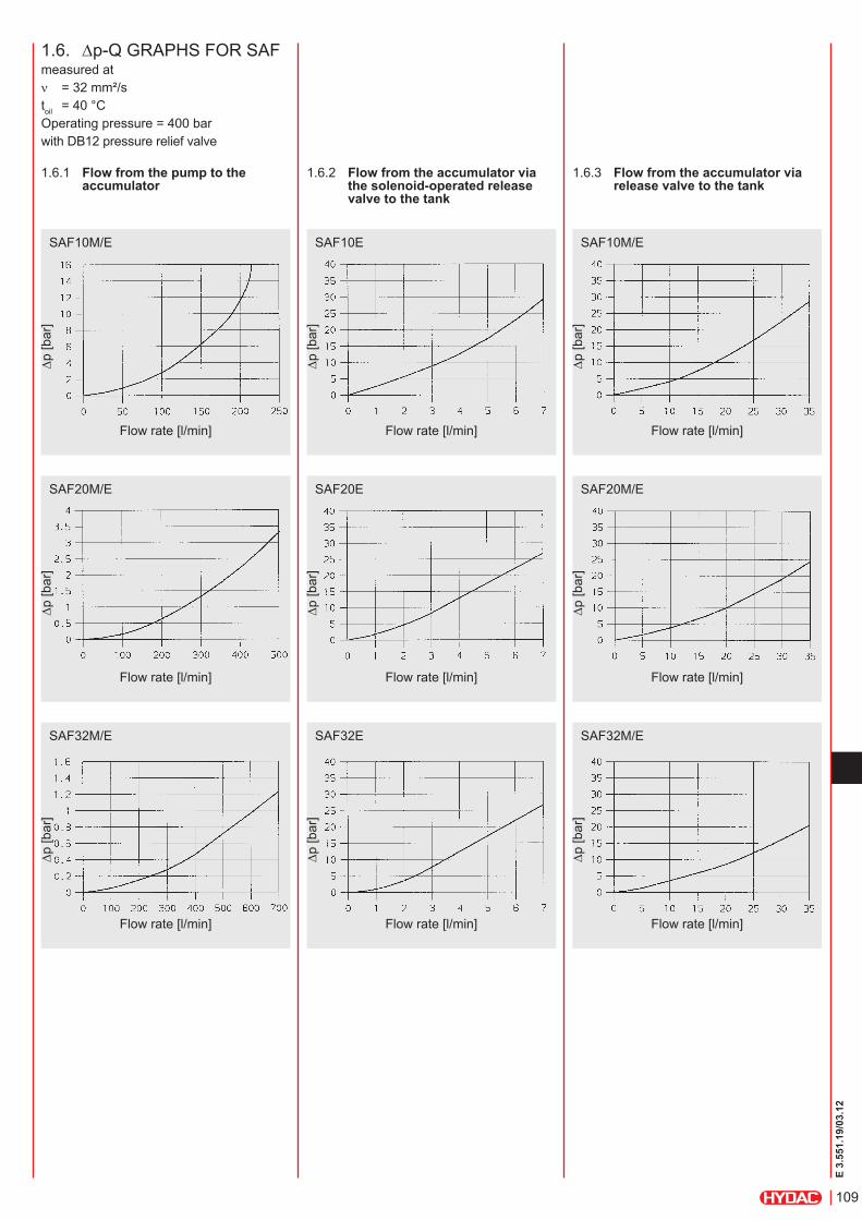
1.6. ∆p-Q GRAPHS FOR SAFmeasured atν = 32 mm²/stoil = 40 °COperating pressure = 400 barwith DB12 pressure relief valve
1.6.1 Flow from the pump to the accumulator
1.6.2 Flow from the accumulator via the solenoid-operated release valve to the tank
1.6.3 Flow from the accumulator via release valve to the tank
SAF10M/E
∆p [b
ar]
Flow rate [l/min]
SAF10E SAF10M/E
∆p [b
ar]
Flow rate [l/min]
∆p [b
ar]
Flow rate [l/min]
SAF20M/E
∆p [b
ar]
Flow rate [l/min]
SAF20E SAF20M/E
∆p [b
ar]
Flow rate [l/min]
∆p [b
ar]
Flow rate [l/min]
SAF32M/E
∆p [b
ar]
Flow rate [l/min]
SAF32E SAF32M/E
∆p [b
ar]
Flow rate [l/min]
∆p [b
ar]
Flow rate [l/min]

110
E 3.
551.
19/0
3.12
sAF 20 e 1 2 Y 1 t 210 A – s 13 – Lpi
safety and shut off block Series SAF
size of main shut-off valve 10 = DN10 20 = DN20 32 = DN32 32-3 = DN32 with 3 pressure relief valves NG12 50 = DN50
type of discharge M = manual discharge E = solenoid-operated and manual discharge
Block material 1 = carbon steel other materials 1)
Material of seals (elastomer) 2 = NBR (Perbunan) 5 = EPDM 6 = FKM (Viton®) 7 = others
type of directional poppet valve Y = open when de-energised (2/2 directional valve WSM06020Y) Z = closed when de-energised (2/2 directional valve WSM06020Z, only up to 350 bar)
type of voltage - directional poppet valve 1 = 24 V DC 2 = 115 V AC 3 = 230 V AC 6 = 120 V AC 7 = others
pressure relief valve T... = pressure-set and lead-sealed by TÜV N... = pressure-set without TÜV 1)
pressure setting e.g. 210 bar
threaded connection to A = ISO 228 (BSP) B = DIN 13, to ISO 965/1 (metric) 1) C = ANSI B1.1 (UNF, O-ring seal to SAE) 1)
Adapter to accumulator (see Point 7.) e.g. S13 = ISO 228 - G 2A
Additional equipment (see point 5.4) L = lockable main shut-off valve (for use with padlock) LPI = model L with additional position monitoring (inductive proximity switch) LPM = model L with additional position monitoring (mechanical limit switch with roller lever) LS = lockable release valve
Accessories (Please give full details when ordering: see Point 7. Accessories)
2. MoDeL coDe For sAF (also order example)
1) On request
111
E 3.
551.
19/0
3.12
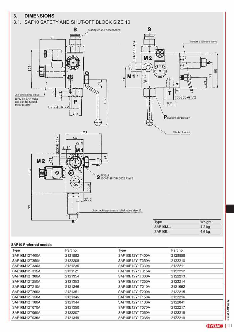
3. DiMensions3.1. SAF10 SAFETY AND SHUT-OFF BLOCK SIZE 10
S adapter see Accessories
2/2 directional valve(only on SAF 10E) coil can be turned through 360°
pressure release valve
system connection
Shut-off valve
M33x2 ISO 6149/DIN 3852 Part 3
direct acting pressure relief valve size 12
sAF10 preferred modelsType Part no. Type Part no.SAF10M12T400A 2121582 SAF10E12Y1T400A 2125858SAF10M12T350A 2122208 SAF10E12Y1T350A 2122210SAF10M12T330A 2121236 SAF10E12Y1T330A 2122211SAF10M12T315A 2121121 SAF10E12Y1T315A 2122212SAF10M12T300A 2121354 SAF10E12Y1T300A 2122213SAF10M12T250A 2121353 SAF10E12Y1T250A 2122214SAF10M12T210A 2121346 SAF10E12Y1T210A 2121662SAF10M12T200A 2121351 SAF10E12Y1T200A 2122215SAF10M12T150A 2121345 SAF10E12Y1T150A 2122216SAF10M12T100A 2121344 SAF10E12Y1T100A 2122041SAF10M12T070A 2121350 SAF10E12Y1T070A 2122217SAF10M12T050A 2122207 SAF10E12Y1T050A 2122218SAF10M12T035A 2121349 SAF10E12Y1T035A 2122219
Type WeightSAF10M... 4.2 kgSAF10E... 4.6 kg

112
E 3.
551.
19/0
3.12
3.2. SAF20 SAFETY AND SHUT-OFF BLOCK SIZE 20
S adaptersee Accessories
pressure releasevalve
system connection
Shut-off valve
2/2 directional valve(only on SAF 20E) coil can be turned through 360°
M33x2 ISO 6149/DIN 3852 Part 3
direct acting pressure relief valve size 12
sAF20 preferred modelsType Part no. Type Part no.SAF20M12T400A 2120317 SAF20E12Y1T400A 2121022SAF20M12T350A 2120434 SAF20E12Y1T350A 2121979SAF20M12T330A 2120323 SAF20E12Y1T330A 2120394SAF20M12T315A 2120324 SAF20E12Y1T315A 2120833SAF20M12T300A 2120332 SAF20E12Y1T300A 2120836SAF20M12T250A 2120432 SAF20E12Y1T250A 2120851SAF20M12T210A 2120319 SAF20E12Y1T210A 2120320SAF20M12T200A 2120325 SAF20E12Y1T200A 2120835SAF20M12T150A 2120330 SAF20E12Y1T150A 2120832SAF20M12T100A 2120401 SAF20E12Y1T100A 2120369SAF20M12T070A 2120326 SAF20E12Y1T070A 2120849SAF20M12T050A 2122172 SAF20E12Y1T050A 2121000SAF20M12T035A 2120281 SAF20E12Y1T035A 2122220
Type WeightSAF20M... 6.8 kgSAF20E... 7.2 kg

113
E 3.
551.
19/0
3.12
3.3. SAF32 SAFETY AND SHUT-OFF BLOCK SIZE 32
S adaptersee Accessories
hex. socket cap screw M16x45 torque 130 Nmsupplied as part of S adapter
system connection
Shut-off valve
pressure release valve
direct acting pressure relief valve size 12
2/2 directional valve(only on SAF 32E) coil can be turned through 360°
sAF32 preferred models
Type Part no. Type Part no.SAF32M12T400A 2125856 SAF32E12Y1T400A 2123123SAF32M12T350A 2122230 SAF32E12Y1T350A 2122221SAF32M12T330A 2122231 SAF32E12Y1T330A 2120371SAF32M12T315A 2121136 SAF32E12Y1T315A 2122222SAF32M12T300A 2120837 SAF32E12Y1T300A 2120834SAF32M12T250A 2122233 SAF32E12Y1T250A 2122223SAF32M12T210A 2120321 SAF32E12Y1T210A 2120318SAF32M12T200A 2121135 SAF32E12Y1T200A 2122224SAF32M12T150A 2121134 SAF32E12Y1T150A 2122225SAF32M12T100A 2121129 SAF32E12Y1T100A 2122226SAF32M12T070A 2122234 SAF32E12Y1T070A 2122227SAF32M12T050A 2121137 SAF32E12Y1T050A 2122228SAF32M12T035A 2121125 SAF32E12Y1T035A 2122229
Type WeightSAF32M... 12.0 kgSAF32E... 12.4 kg

114
E 3.
551.
19/0
3.12
4. spAre pArts
SAF Block SAF10M SAF10E
SAF20M SAF20E
SAF32M SAF32E
Description Item Dimensionsrepair kit Part no.
2122238 (NBR) 2122240 (FPM)
Part no. 2122242 (NBR) 2122244 (FPM)
Part no. 2122246 (NBR) 2122248 (FPM)consisting of:
Spindle 1Disc 2O-ring 3 10x2 15x2.5 20x3Ball 4Switching handle 5Spindle 6O-ring 7 6x2Set screw 8 M4x6 M4x10Slip-in orifice 9 Ø1.5 mm (Qmax - 25.5 l/min)O-ring 11 17x2Back-up ring 12 11.7x15x1O-ring 13 11x2Sealing cup 14O-ring 15 21x2 34x2.5 56.7x2.8O-ring 16 23.47x2.62Back-up ring 17 18.3x21.5x1O-ring 18 18x2O-ring 19 29.7x2.8 29.7x2.8 37.2x3Blanking plug 20
21 22 23
G 1/8 G 1/4 – –
G 1/8 G 1/4 G 3/8 G 1/2
G 1/8 G 1/4 G 3/8 G 1/2
2/2 directional valve assembly(only for E-version)
10 Part no. 3156869 (WSM 06020Y - open when de-energised) 3156873 (WSM 06020Z - closed when de-energised)277645
Blanking plug assembly(converts "E" version to "M" version)seal kitconsists of: Items 3, 7, 8, 11, 12, 13, 14, 15, 16, 17, 18, 19, 20, 21, 22, 23
Part no. 2121699 (NBR) 2121701 (FPM)
Part no. 2121703 (NBR) 2121705 (FPM)
Part no. 2121707 (NBR) 2121709 (FPM)
spindle repair kitconsists of: Items 6, 7, 8
Part no. 2115648 (NBR) 2115649 (FPM)

115
E 3.
551.
19/0
3.12
5. speciAL MoDeLs5.1. TYPE SAF32-3M(E)With 3 direct acting pressure relief valves size 12 (max. operating pressure 400 bar)
hex. socket cap screw M16x45 torque 130 Nmsupplied as part of S adapter
Adaptersee Accessories
system connection
pressure release valve
2/2 directional valve(only on SAF32-3E) coil can be turned through 360°
direct actingpressure relief valve size 12
SAF32-3M
SAF32-3E
Type WeightSAF32-3M... 24 kgSAF32-3E... 25 kg

116
E 3.
551.
19/0
3.12
5.2. TYPE SAF50M(E)for large flows with 3 direct acting pressure relief valves size 12 (max. operating pressure 400 bar)
system connection
pressure release valve
hex. socket cap screw M16x45 torque 130 Nmsupplied as part of S adapter
S adapteron request
2/2 directional valveonly on SAF50E coil can be turned through 360°
direct actingpressure relief valve size 12
SAF50M
SAF50E
Type WeightSAF50M... 25 kgSAF50E... 26 kg

117
E 3.
551.
19/0
3.12
5.3. TYPE SA32M(E)29with pilot-operated pressure relief valve (Qmax = 600 l/min) (max. operating pressure 330 bar)
for pressurised tank linesa valve "TVY" with external oil return must be used
S adaptersee Accessories
hex. socket cap screw M16x45supplied as part of S adapter
system connection
Shut-off valve

118
E 3.
551.
19/0
3.12
pressure release valve
2/2 directional valve(only on SA31E29) coil can be turned through 360°
pilot-operatedpressure relief valve size 32
Pilot-operated pressure relief valve seize 32
inle
t pre
ssur
e [b
ar]
Flow rate [l/min]
Lowest setting pressure [bar]m
in. s
ettin
g pr
essu
re,
circ
ulat
ing
pres
sure
[b
ar]
Flow rate [l/min]
sA32e29tV
sA32e29tVY The safety and shut-off block SA32M(E)29 is equipped with a pilot-operated pressure relief valve size 32 for high flow rates up to 600 l/min.The E version of the safety and shut-off block has a solenoid-operated 2-way directional valve for automatic pressure release of the accumulator and the hydraulic system in an emergency or for shut-down.For unpressurized tank lines, valve type "TV" must be used (with internal oil return to tank).For pressurised tank lines, valve type "TVY" is recommended (with external oil return to tank). Two different models of the 2-way directional valve are available:– WSM06020Y (open when de-energised)– WSM06020Z (closed when
de-energised)
sA32M29tVY
sA32M29tV
Type WeightSA32M29... 22.5 kgSA32E29... 23.5 kg

119
E 3.
551.
19/0
3.12
5.4. SAFETY AND SHUT-OFF BLOCK WITH ADDITIONAL EQUIPMENTSafety and shut-off blocks are available with a device to enable the shut-off valve to be locked in the open or closed position using a padlock.It is also possible to fit inductive proximity switches or roller-actuated limit switches to control the open and closed position of the shut-off valve.
supplementary equipment LpM supplementary equipment Ls
supplementary equipment L supplementary equipment Lpi
inductive proximity switchto monitor the open or closed position of the shut-off valve
switching distance 2 mm
optional locking deviceto enable the shut-off valve to be locked in the open or closed position using a padlock
open
closed
mechanical limit switchwith roller lever to monitor the open or closed position of the shut-off valve
optional locking deviceto enable the shut-off valve to be locked in the open or closed position using a padlock
closed
open
optional locking deviceto enable the shut-off valve to be locked in the open or closed position using a padlock
optional locking devicefor pressure release valve
open
open
closed
closed

120
E 3.
551.
19/0
3.12
5.5. SAFETY AND SHUT-OFF BLOCK FOR FRONT PANEL MOUNTING
The safety and shut-off block consists of a valve block, a built-in pressure relief valve, a main shut-off valve and a manually operated pressure release valve.This block is mounted on a front panel with 3 M8 screws. Ports "P" and "T" are located on the mounting side.Advantages: The compact design means that the block occupies a minimum of space and ensures minimum maintenance.Specifications: Type: SA6M10T... Size: DN10 Max. operating pressure: 350 bar Direct acting pressure relief valve: NG6
5.6. SAFETY AND SHUT-OFF BLOCK WITH 2-WAY CARTRIDGE VALVE (LOGIC ELEMENT)
This safety and shut-off block consists of a valve block, an integral pressure relief valve and a solenoid-operated 2-way cartridge valve which replaces the main shut-off valve.Advantages: In addition to its compact construction, this model is capable of rapid switching to control the oil flow.5.6.1 Function when using 4/2
directional valveWhen the 4/2 directional valve is in the switching position shown (open when de-energised), the spring chamber of the logic element is pressurised via the accumulator pressure; the path from P to S is blocked and the hydraulic accumulator is automatically shut off from the system. By connecting the accumulator via the slip-in orifice in the pilot valve to the tank, it will slowly discharge.When the 4/2 directional poppet valve is in the discharge position (energised) the spring chamber of the logic element is discharged, the path from P to S is open and the accumulator is charged.Technical specifications:Type Size Max.
operating pressure
Pressure relief valve 1)
SA20A50T... DN20 400 bar NG12 (2)SA32A50T... DN30 400 bar NG12 (3)SA40A50T... DN40 400 bar NG12 (3)
1) number of pressure relief valves
5.6.2 Function when using 3/2 directional poppet valve
When the 3/2 directional poppet valve is in the switching position shown (open when de-energised), the spring chamber of the logic element is pressurised via the system pressure; the path from P to S is blocked and the accumulator is shut off from the system. When the 3/2 directional poppet valve is in the discharge position (energised) the spring chamber of the logic element is discharged, the path from P to S is open and the accumulator is charged.If the pump breaks down or if it is switched off, the 3/2 directional poppet valve reverts to the "open when de-energised" position; the accumulator pressure shuts off the logic element via the shuttle change-over valve and shuts off the accumulator from the system.Technical specifications:Type Size Max.
operating pressure
Pressure relief valve 1)
SA20A51T... DN20 400 bar NG12 (2)SA32A51T... DN30 400 bar NG12 (3)SA40A51T... DN40 400 bar NG12 (3)
1) number of pressure relief valves
121
E 3.
551.
19/0
3.12
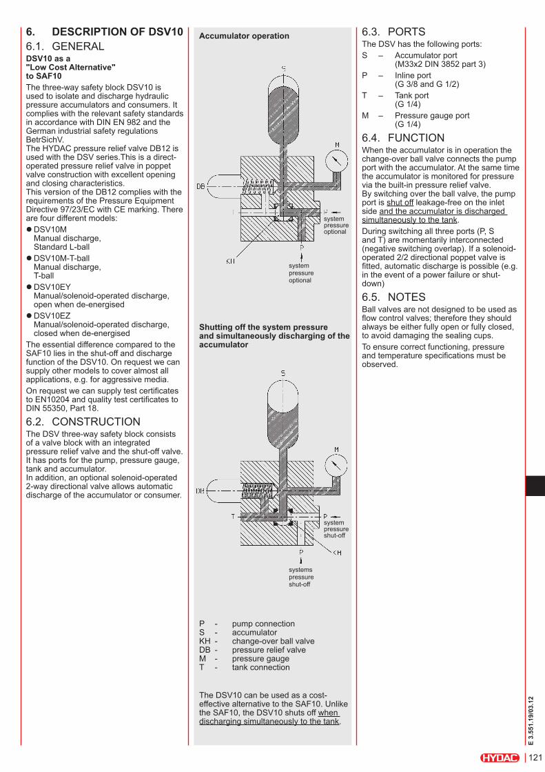
6. Description oF DsV106.1. GENERALDsV10 as a "Low cost Alternative" to sAF10The three-way safety block DSV10 is used to isolate and discharge hydraulic pressure accumulators and consumers. It complies with the relevant safety standards in accordance with DIN EN 982 and the German industrial safety regulations BetrSichV. The HYDAC pressure relief valve DB12 is used with the DSV series.This is a direct-operated pressure relief valve in poppet valve construction with excellent opening and closing characteristics. This version of the DB12 complies with the requirements of the Pressure Equipment Directive 97/23/EC with CE marking. There are four different models:
zDSV10M Manual discharge, Standard L-ball zDSV10M-T-ball Manual discharge, T-ball zDSV10EY Manual/solenoid-operated discharge, open when de-energised zDSV10EZ Manual/solenoid-operated discharge, closed when de-energised
The essential difference compared to the SAF10 lies in the shut-off and discharge function of the DSV10. On request we can supply other models to cover almost all applications, e.g. for aggressive media.On request we can supply test certificates to EN10204 and quality test certificates to DIN 55350, Part 18.
6.2. CONSTRUCTIONThe DSV three-way safety block consists of a valve block with an integrated pressure relief valve and the shut-off valve. It has ports for the pump, pressure gauge, tank and accumulator. In addition, an optional solenoid-operated 2-way directional valve allows automatic discharge of the accumulator or consumer.
Accumulator operation
shutting off the system pressure and simultaneously discharging of the accumulator
The DSV10 can be used as a cost-effective alternative to the SAF10. Unlike the SAF10, the DSV10 shuts off when discharging simultaneously to the tank.
P - pump connection S - accumulator KH - change-over ball valve DB - pressure relief valve M - pressure gauge T - tank connection
system pressure optional
system pressure optional
system pressure shut-off
systems pressure shut-off
6.3. PORTSThe DSV has the following ports:S – Accumulator port (M33x2 DIN 3852 part 3)P – Inline port (G 3/8 and G 1/2)T – Tank port (G 1/4)M – Pressure gauge port (G 1/4)
6.4. FUNCTIONWhen the accumulator is in operation the change-over ball valve connects the pump port with the accumulator. At the same time the accumulator is monitored for pressure via the built-in pressure relief valve. By switching over the ball valve, the pump port is shut off leakage-free on the inlet side and the accumulator is discharged simultaneously to the tank.During switching all three ports (P, S and T) are momentarily interconnected (negative switching overlap). If a solenoid-operated 2/2 directional poppet valve is fitted, automatic discharge is possible (e.g. in the event of a power failure or shut-down)
6.5. NOTESBall valves are not designed to be used as flow control valves; therefore they should always be either fully open or fully closed, to avoid damaging the sealing cups.To ensure correct functioning, pressure and temperature specifications must be observed.

122
E 3.
551.
19/0
3.12
6.6. SPECIFICATIONS6.6.1 symbols
6.6.2 type of constructionBall valve isolating devicePressure relief valve is a direct-acting poppet valvePoppet valve is pilot-operated6.6.3 MaterialsHousing and blanking plug in steel, surface protection: phosphated. Ball in steel, hard-chromed. Pressure relief valve and poppet valve in high tensile steel, closing element in hardened and ground steel, wear-resistant, surface protection: phosphated. Ball seal in high quality synthetic material (POM) soft seals in Perbunan (NBR). Cranked handle SW09 in red anodised aluminium.
DSV10M
DSV10M-T-ball
DSV10EY
DSV10EZ
6.6.4 installation positionoptional6.6.5 Operating fluidsMineral oil to DIN 51524 Part 1 and part 2 (other fluids on request)Viscosity range: Min. 10 mm²/s Max. 380 mm²/sFiltration: Max. permitted contamination of the operating fluid to SAE AS 4059 Class 11. We therefore recommend a filter with a minimum retention rate of ß20 ≥ 100. The fitting of filters and the regular replacement of filter elements guarantees correct operation, reduces wear and tear and increases the service life.6.6.6 permitted operating temperature-10 °C ... +80 °C(ambient temperature for E version limited to -10 °C ... +60 °C)6.6.7 Maximum operating pressure350 bar6.6.8 ∆p - Q graphmeasured at toil = 50 °C ν = 30 mm²/s
Flow rate from P to S
Flow rate from S to T
p [b
ar]
Q [l/min]
p [b
ar]
Q [l/min]
6.6.9 Model with solenoid-operated pressure relief
type Solenoid-operated by means of pressure-tight, oil-immersed, single-stroke solenoids in accordance with VDE 0580. Actuating solenoid with male connector to DIN 43650, standard for general industrial applications, available for 24 V DC and 230 V AC.type of current DC solenoid When connected to AC voltage the necessary DC voltage is produced by means of a bridge rectifier connector.Voltage tolerance ±15% of nominal voltagenominal current dependent on the nominal voltage 24 V DC 0.80 A230 V AC 0.11 Apower consumption: p20 = 18 WDuty Continuous switching time Dependent on symbol, pressure across the individual ports and flow rate.WSM06020Y: on: 50 ms, off: 35 msWSM06020Z: on: 35 ms, off: 50 ms
6.7. SPARE PARTSPlease see brochure:
z 3-way safety block DSV No. 5.251
123
E 3.
551.
19/0
3.12
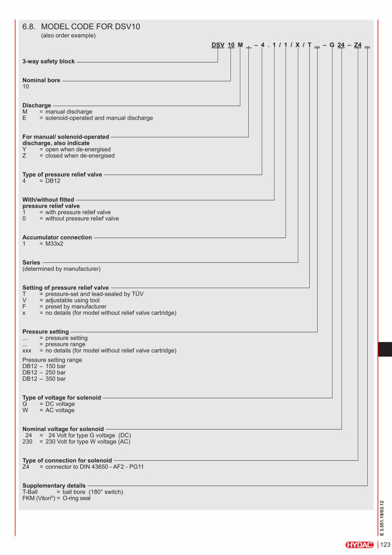
6.8. MODEL CODE FOR DSV10 (also order example)
DsV 10 M . – 4 . 1 / 1 / X / t ... – G 24 – Z4 ...
3-way safety block
nominal bore 10
Discharge M = manual discharge E = solenoid-operated and manual discharge
For manual/ solenoid-operated discharge, also indicate Y = open when de-energised Z = closed when de-energised
type of pressure relief valve 4 = DB12
With/without fitted pressure relief valve 1 = with pressure relief valve 0 = without pressure relief valve
Accumulator connection 1 = M33x2
series (determined by manufacturer)
setting of pressure relief valve T = pressure-set and lead-sealed by TÜV V = adjustable using tool F = preset by manufacturer x = no details (for model without relief valve cartridge)
pressure setting ... = pressure setting ... = pressure range xxx = no details (for model without relief valve cartridge)Pressure setting range DB12 – 150 bar DB12 – 250 bar DB12 – 350 bar
type of voltage for solenoid G = DC voltage W = AC voltage
nominal voltage for solenoid 24 = 24 Volt for type G voltage (DC) 230 = 230 Volt for type W voltage (AC)
type of connection for solenoid Z4 = connector to DIN 43650 - AF2 - PG11
supplementary details T-Ball = ball bore (180° switch) FKM (Viton®) = O-ring seal

124
E 3.
551.
19/0
3.12
6.9. DIMENSIONSDSV10 3-way safety block
2/2 directional valve2SV5
system connectionoptional
4 x mounting hole Ø9
Shut-off valve
system connectionoptional
M33x2 ISO 6149/DIN 3852 Part 3
Pressure relief valve DB12
Type B [mm] WeightDSV10M... 45 3.5 kgDSV10E... 60 3.9 kg
DsV10 preferred modelsType Part no. Type Part no.DSV-10-M-4.0/1/X/XXXX 555999 DSV-10-EY-4.0/1/X/XXXX-G24-Z4 557367DSV-10-M-4.1/1/X/T035 555968 DSV-10-EY-4.1/1/X/T035-G24-Z4 555980DSV-10-M-4.1/1/X/T050 555969 DSV-10-EY-4.1/1/X/T050-G24-Z4 555981DSV-10-M-4.1/1/X/T070 555970 DSV-10-EY-4.1/1/X/T070-G24-Z4 555982DSV-10-M-4.1/1/X/T100 555971 DSV-10-EY-4.1/1/X/T100-G24-Z4 555983DSV-10-M-4.1/1/X/T150 555972 DSV-10-EY-4.1/1/X/T150-G24-Z4 555984DSV-10-M-4.1/1/X/T200 555973 DSV-10-EY-4.1/1/X/T200-G24-Z4 555985DSV-10-M-4.1/1/X/T210 555974 DSV-10-EY-4.1/1/X/T210-G24-Z4 555986DSV-10-M-4.1/1/X/T250 555975 DSV-10-EY-4.1/1/X/T250-G24-Z4 555987DSV-10-M-4.1/1/X/T300 555976 DSV-10-EY-4.1/1/X/T300-G24-Z4 555988DSV-10-M-4.1/1/X/T315 555977 DSV-10-EY-4.1/1/X/T315-G24-Z4 555989DSV-10-M-4.1/1/X/T330 555978 DSV-10-EY-4.1/1/X/T330-G24-Z4 555990DSV-10-M-4.1/1/X/T350 555979 DSV-10-EY-4.1/1/X/T350-G24-Z4 555991
coil can be turned through 360°

125
E 3.
551.
19/0
3.12
Type Accumulator type
Volume [l]
Adapter Part no. 1) NBR/Carbon steel
Diag. D1 [mm]
D2 [mm]
O-ring Corresponding S adapter
Part no. 1) NBR/Carbon steel
SAF10/20 DSV10
SK210/350 - 2.5 ... 7.5 K 406 374929 1 G 1 1/4 G 1 35x3 S 12 369480SK210/350 - 10 ... 45 K 408 374931
2 G 2G 1 1/2 53x3 S 13 369481
SAF32 SK210/350 - 50 ... 120 K 409 374933 G 2 62x3 S 309 3667151) others on request
7.3. ADAPTERS FOR PISTON ACCUMULATORS
Diagram 1 Diagram 2
Type Accumulator type
Volume [l]
D1 Thread Part no. 1) NBR/Carbon steel
Adapter K SW
L1 [mm]
L2 [mm]
D2 [mm]
O-ring
SAF10/20 DSV10
SBO...E- 0.075 ... 1.4G 1/2 A 369485 S 30
4114
17.533 22x3
SBO...A6- 0.1 ... 210-1.3SBO...E- 2.0 ... 3.5
G 3/4 A 369486 S 31 16 40 28x3SBO...A6- 1.3 ... 4
¹) others on request
Type Accumulator type
Volume [l]
Adapter Part no. 1) NBR/Carbon steel
Corresponding S adapter
Part no. 1) NBR/Carbon steel
SAF10/20 and DSV10SB35 2.5 ... 50 N500 367229
S 13 369481SAF32 S 309 366715
7. Accessories: ADApters For sAF/DsV107.1. ADAPTERS FOR LOW PRESSURE BLADDER ACCUMULATORS
7.2. ADAPTERS FOR DIAPHRAGM ACCUMULATORS
N500
O-ring 102x3
S adapter
safety andshut-off block
O-ring
O-ring
126
E 3.
551.
19/0
3.12
Type Accumulator type Volume [l]
D1 Thread Adapter Part no. 2) NBR/Carbon steel
K SW [mm]
L1 [mm]
L2 [mm]
D2 [mm]
O-ring [mm]
Diag.
SAF10SAF20DSV10
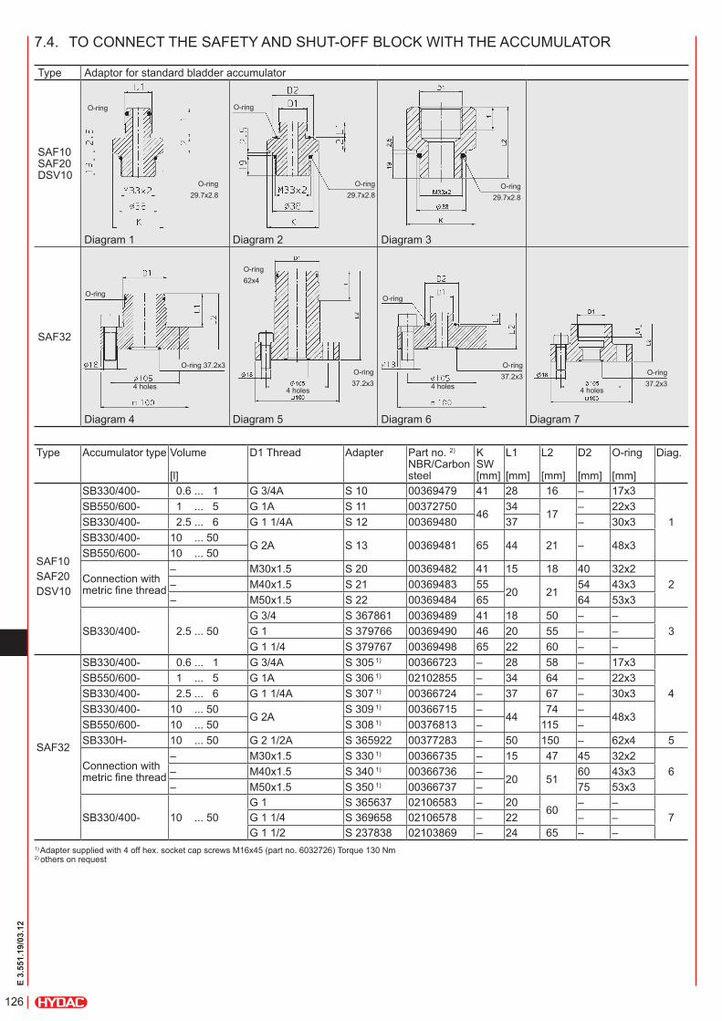
SB330/400- 0.6 ... 1 G 3/4A S 10 00369479 41 28 16 – 17x3
1SB550/600- 1 ... 5 G 1A S 11 00372750
4634
17– 22x3
SB330/400- 2.5 ... 6 G 1 1/4A S 12 00369480 37 – 30x3SB330/400- 10 ... 50
G 2A S 13 00369481 65 44 21 – 48x3SB550/600- 10 ... 50
Connection with metric fine thread
– M30x1.5 S 20 00369482 41 15 18 40 32x22– M40x1.5 S 21 00369483 55
20 2154 43x3
– M50x1.5 S 22 00369484 65 64 53x3
SB330/400- 2.5 ... 50G 3/4 S 367861 00369489 41 18 50 – –
3G 1 S 379766 00369490 46 20 55 – –G 1 1/4 S 379767 00369498 65 22 60 – –
SAF32
SB330/400- 0.6 ... 1 G 3/4A S 305 1) 00366723 – 28 58 – 17x3
4SB550/600- 1 ... 5 G 1A S 306 1) 02102855 – 34 64 – 22x3SB330/400- 2.5 ... 6 G 1 1/4A S 307 1) 00366724 – 37 67 – 30x3SB330/400- 10 ... 50
G 2AS 309 1) 00366715 –
4474 –
48x3SB550/600- 10 ... 50 S 308 1) 00376813 – 115 –SB330H- 10 ... 50 G 2 1/2A S 365922 00377283 – 50 150 – 62x4 5
Connection with metric fine thread
– M30x1.5 S 330 1) 00366735 – 15 47 45 32x26– M40x1.5 S 340 1) 00366736 –
20 5160 43x3
– M50x1.5 S 350 1) 00366737 – 75 53x3
SB330/400- 10 ... 50G 1 S 365637 02106583 – 20
60– –
7G 1 1/4 S 369658 02106578 – 22 – –G 1 1/2 S 237838 02103869 – 24 65 – –
1) Adapter supplied with 4 off hex. socket cap screws M16x45 (part no. 6032726) Torque 130 Nm 2) others on request
7.4. TO CONNECT THE SAFETY AND SHUT-OFF BLOCK WITH THE ACCUMULATOR
Type Adaptor for standard bladder accumulator
SAF10 SAF20 DSV10
Diagram 1 Diagram 2 Diagram 3
SAF32
Diagram 4 Diagram 5 Diagram 6 Diagram 7
O-ring
O-ring29.7x2.8
O-ring
O-ring29.7x2.8
O-ring29.7x2.8
O-ring
O-ring 37.2x3
4 holes
O-ring62x4
4 holes
O-ring37.2x3
O-ring
O-ring37.2x3
4 holes
O-ring37.2x3
4 holes

127
E 3.
551.
19/0
3.12
8. noteThe information in this brochure relates to the operating conditions and applications described.For applications and operating conditions not described, please contact the relevant technical department.Subject to technical modifications.
HYDAc technology GmbH Industriegebiet 66280 sulzbach/saar, Germany Tel.: +49 (0) 68 97 / 509 - 01 Fax: +49 (0) 68 97 / 509 - 464 Internet: www.hydac.com E-Mail: [email protected]
Consisting of: Isolator valve AG (Part no. 611903) with bleed valve swivel nut, positional lock nut and test point to DIN 16271 and test point adapter PA with seals (Part no. 370754)
7.5. GAUGE ISOLATOR VALVE
swivel nut
Test point adapter PA
positional lock nut
Vent screw
test point

128
E 3.
551.
19/0
3.12

91
E 3.
553.
1/03
.12
Hydraulic Accumulators with Back-Up Nitrogen Bottles
1. GENERALTo complete the accumulator range, HYDAC provides a variety of useful accessory products. They guarantee correct installation and optimum functioning of HYDAC hydraulic accumulators. These include, amongst others, nitrogen bottles which can be used to back up bladder and piston accumulators. Nitrogen bottles used as back-ups increase the gas volume in the accumulator. This means that smaller accumulators can be used for the same gas volume and costs can be reduced. To assist selection the Simulation Program ASP can be downloaded from www.hydac.com.
For further information, please turn to the sections:
zBladder Accumulators Standard No. 3.201 zPiston Accumulators No. 3.301
2. BACK-UP VERSIONS2.1. CONSTRUCTIONBased on bladder accumulator models 20 ... 50 l, the gas-side of these transfer accumulators is designed specially for connecting to nitrogen bottles. A diffuser rod prevents damage to the bladder when the accumulator is charged. This construction can also be used for the separation of fluids (taking into account the volume ratios which apply to bladder accumulators).
Adapter FPS
Piping
Nitrogen bottleHydraulic accumulator
Oil valve
Adapter
Type 2
Type 1

92
E 3.
553.
1/03
.12
Type 1
2.2. DIMENSIONS
Type 2
2.3. SPARE PARTSDescription ItemRepair kit consisting of:
Bladder 2Retaining nut 4O-ring 7.5x2.0 1) 7Washer 15O-ring 80x5 1) 16Seal ring 20Support ring 23O-ring 48x3 1) 27O-ring 22x2.5 1) 31O-ring 11x2 1) 33Diffuser rod 30
Anti-extrusion ring 14Recommended spare parts1) For code 663 and 665 different dimensions Item 1 not available as a spare part. Item 25 must be ordered separately, See Bladder Accumulators Standard, No. 3.201 (see Point 4.2.). Item 32 Type 1 is standard.For other spare parts, see Point 3.
2.4. REPAIR kITSNBR, carbon steelNom. volumes: 20 ... 52 litres Standard gas valve
Nominal volume [l] Part no.20 0311950024 0311950232 0311949852 03119499
Nominal volume [l]
Effect. gas volume [l]
Weight [kg]
A max. [mm]
20 17.5 53.5 90524 24 72 107032 32.5 89 142050 47.5 119.5 1930

93
E 3.
553.
1/03
.12
3.3. TECHNICAl DATA3.3.1 Model code (also order example)
SN360 - 50 AA / 010 U - 360 D DSeriesCode letter No details = standard B = bladder accumulator shell 1) k = piston accumulator cylinder 2) M = diaphragm accumulator half-sections 3)
Nominal volume [l]Connection typeConnection type on connection side* A = ISO 228 (BSP) B = DIN 13 to ISO 965/1 (metric) C = ANSI B1.1 (UNF seal SAE) D = ANSI B2.1 F = flangeDrain side (condensate)* A = ISO 228 (BSP) B = DIN 13 to ISO 965/1 (metric) C = ANSI B1.1 (UNF seal SAE) D = ANSI B2.1 F = flange 1 = sealed with blanking plug 2 = with condensate drain, hex. socket cap screw 3 = with condensate drain valve 4 = with Minimess valveMaterial codeMaterial (of connection) 0 = no components 1 = carbon steel 3 = stainless steel 4 = carbon steel with protective coating 6 = low temperature steelHousing material 1 = carbon steel 2 = carbon steel with protective coating 4 = stainless steel 6 = low temperature steelSeal material (elastomer) 0 = no elastomer used 2 = NBR (Perbunan) 4 = IIR (Butyl) 5 = TT-NBR 6 = FKM (fluoro rubber)Certificate code U = PED 97/23/EC 4)
Permitted operating pressure [bar]Size for connection side (see Table 3.3.2)Size for drain side (see Table 3.3.2) 0 = for type 1-4
3. NITROGEN BOTTLES3.1. DESCRIPTION AND
CONSTRUCTION
3.3.2 Connections*Type
Size
A BSP ISO228
B metric DIN 13 ISO 965/1
C SAE ANSI B1.1
D NPT ANSI B2.1
F Flange connection
A G 1/4" M12x1.5 7/16"-20UNF 1/4"1/2" 3000 PSI Code 61
B G 3/8" M18x1.5 9/16"-18UNF 3/8" 3/4"C G 1/2" M22x1.5 3/4"-16 UNF 1/2" 1"D G 3/4" M27x2 1 1/16"-12UN 3/4" 1 1/4"E G 1" M33x2 1 5/16"-12UN 1" 1 1/2"F G 1 1/4" M42x2 1 5/8"-12UN 1 1/4" 2"
G G 1 1/2" M48x2 1 7/8"-12UN 1 1/2"1/2" 6000 PSI Code 62
H G 2" M14x1.5 2 1/2"-12UN 2" 3/4"I G 1 3/4" M8k M16x1.5 1 1/4"l 7/8"-14 UNF 5/8" 1 1/2"M 2"S Special model* not all combinations are possible, others on request
1) see catalogue section: Bladder Accumulators Standard, No. 3.201 2) see catalogue section: Piston Accumulators, No. 3.301 3) see catalogue section: Diaphragm Accumulators, No. 3.100 4) see catalogue section: Accumulators, No. 3.000, Point 3.
HYDAC nitrogen bottles are used to take in and store nitrogen. HYDAC offers a wide selection of bottle types, such as forged vessels and bladder shells or piston cylinders.
3.2. ADVANTAGESUsing HYDAC nitrogen bottles provides the following benefits:
zCost-effective increase of the accumulator volume and as a result z smaller accumulators for the same gas volume.
Nitrogen bottle
Minimess connection

94
E 3.
553.
1/03
.12
4. ACCESSORIES4.1. CHARGING AND TESTING BlOCk F + P4.1.1 DescriptionThe HYDAC charging and testing block F+P is used to charge and test back-up type hydraulic accumulators. It has connections for the charging and testing unit FPU-1 and for pressure gauges. As a safety function, a gas safety valve GSV6 (see catalogue section given below) can be fitted. In addition, it allows the back-up nitrogen bottles to be shut off from the hydraulic accumulator.
z Safety Equipment for Hydraulic Accumulators No. 3.552
4.1.2 Hydraulic circuit with charging and testing block
nitrogen bottles
hydraulic accumulator
safety and shut-off block
charging and testing block
connection for gas safety valve
connection for charging and testing unit FPU-1*
* For further information, see catalogue section: Universal charging and testing unit FPU-1 No. 3.501
4.1.3 Preferred types / Spare parts
Designation Max. operating pressure [bar]
Weight [kg]
Part no.
Seal kit 1)
F+P-16-20SR-6112-02X 400 4.3 850233 2115776
F+P-32-38SR-6112-02X 350 14 552193 21120881) recommended spare parts
3.3.3 Dimensions of standard bottle
Designation Volume[l]
Connections toISO 228
A max. [mm]
Part no.
SN360- 50AA/010U-360DD 50 G 3/4 G 3/4 1615 3176324
SN360- 50AA/010U-360DG 50 G 3/4 G 1 1/2 1615 3418347
SN500- 50AA/010U-500DD 50 G 3/4 G 3/4 1745 3107549
SN600- 50AA/010S-345DD 50 G 3/4 G 3/4 1750 2105042
SN360- 75AA/010U-360DE 75 G 1 G 3/4 2305 3233527
SN360- 75AA/010U-360DG 75 G 1 1/2 G 3/4 2305 3561595

95
E 3.
553.
1/03
.12
4.1.4 Technical specifications / Dimensions Charging and testing block DN 16
charging and testing unitM28x1.5
4 mountingbores
hydraulic accumulator
nitrogen bottle
gas safety valveGSV6 (optional)
connection for pressuregauge (optional)
connection for pressuregauge (optional)
Charging and testing block DN 32
charging and testing unitM28x1.5 4 mounting
bores
hydraulic accumulator
nitrogen bottle
gas safety valveGSV6 (optional) connection for pressure
gauge (optional)
connection for pressuregauge (optional)

96
E 3.
553.
1/03
.12
4.3. NITROGEN CHARGING UNIT
HYDAC nitrogen charging units facilitate fast and cost-effective charging or testing of the required pre-charge pressures in bladder, diaphragm and piston accumulators. They guarantee optimum use of standard nitrogen bottles up to a residual pressure of 20 bar and a maximum accumulator charging pressure of 350 bar. Portable, mobile and stationary types of N2-Server are available. For further information and technical specifications, see catalogue section:
zNitrogen charging units N2-Server No. 2.201
5. NOTEThe information in this brochure relates to the operating conditions and applications described. For applications and operating conditions not described, please contact the relevant technical department. Subject to technical modifications.
HYDAC Technology GmbH Industriegebiet 66280 Sulzbach/Saar, Germany Tel.: +49 (0) 68 97 / 509 - 01 Fax: +49 (0) 68 97 / 509 - 464 Internet: www.hydac.com E-Mail: [email protected]
4.2. CONDENSATE DRAIN SETThe condensate drain set consists of a throttle valve and a suitable condensate draining hose. It is used to drain any condensate from the nitrogen bottle, in a controlled way.
Nitrogen bottle
Draining hose
Throttle valve
Description length [m] Part no.
Condensate drain set0.4 34728201.0 34728231.6 3472824

97
E 3.
501.
26/0
3.12
1. Description1.1. Functionthe HYDAc charging and testing unit FPu-1 is used to charge accumulators with nitrogen or to check or to change the existing pre-charge pressure in accumulators. For this purpose the charging and testing unit is screwed onto the gas valve of the hydraulic accumulator and connected via a hose to a commercial nitrogen bottle. if the nitrogen pressure is only to be checked or reduced, the charging hose does not need to be connected. the unit has a screw-type fitting with a built-in gauge, check valve and a spindle for opening the accumulator gas valve to control the pressure.HYDAc piston and diaphragm accumulators can be charged and checked without the need for adapters. Bladder accumulators, however, require an A3 adapter.please read the operating Manual! no. 3.501.ce
Universal Charging and Testing Unit FPU-1for Bladder, Piston and Diaphragm Accumulators
1.3. SPeciAl moDelS1.2. DeSignthe HYDAc charging and testing unit for bladder, piston and diaphragm accumulators consists of:
zValve body zSpindle zcheck valve zRelease valve zPressure gauge zcharging hose zA3 adapter for bladder accumulators
Release valve
Spindle
check valve
Pressure gauge
For higher pressures, the following special models are available:
z FPS 600 for bladder accumulators up to 600 bar max. pre-charge pressure (see technical information 293715). z FPK 600 for piston, diaphragm and SB800-1.5 accumulators up to 600 bar max. pre-charge pressure (see technical information 297248). z FPH 800 for high pressure bladder accumulators up to 800 bar max. pre-charge pressure (see technical information 242948).
the photo top left shows a possible order option, including accessories.

98
E 3.
501.
26/0
3.12
2. technical specifications2.1. moDel coDe (also order example)
fpU-1 - 250 f 2,5 G2 a1 KUniversal charging and testing unit pmax = 350 bar
Gauge indication range 0 - 10 bar 0 - 145 psi 10 0 - 25 bar 0 - 363 psi 25 0 - 100 bar 0 - 1450 psi 100 0 - 250 bar 0 - 3625 psi 250 0 - 400 bar 0 - 5800 psi 400
charging hose F = for 200 bar nitrogen bottle with connection W24.32x1/14 (Din 477, Part 1) Fm = for 300 bar nitrogen bottle with connection m30x1.5 (Din 477, Part 5 up to April 2002) FW = for 300 bar nitrogen bottle with connection W30x2 (Din 477, Part 5 from April 2002)
length of charging hose 2.5 = 2.5 m 4.0 = 4 m Special lengths on request
adapter G for nitrogen bottles See table, Point 3.6.
adapter a A1 = m16x1.5 A2 = 5/8 - 18 unF A3 = 7/8 - 14 unF A4 = 7/8 - 14 unF A5 = m8x1 A6 = g 3/4 A A7 = g 1/4 A8 = g 3/4 A9 = Vg 8 A10 = 7/8 - 14 unF A11 = m16x2A12 = m16x2 D4 = 5/8 - 18 unF (Part no. 366374) other adapters on request
protective case
accessories - please give full details when ordering(see point 4.)
(A3 is supplied as standard)
1.4. teSting inteRVAlSin general, nitrogen losses on HYDAc hydraulic accumulators are very low. However, a regular check of the gas filling pressure is recommended to prevent the piston from hitting the end cap, or the bladder or diaphragm from becoming too deformed if there is a drop in the pressure p0.
the pre-charge pressure p0 as shown on the label or the accumulator body, must be re-set after every new installation or repair and then checked at least once during the following week. if no nitrogen loss is detected, a further check should be made after approx. 4 months. if after this period no change in the pressure is found, a yearly check should be sufficient.
1.5. ScHemAtic DRAWing
Fluid connection
nitrogen bottle Hydraulic accumulator
Adapter A
mg1 charging hose
Adaptor g Pressure reducer charging and testing unit FPu-1
n2 n2
99
E 3.
501.
26/0
3.12
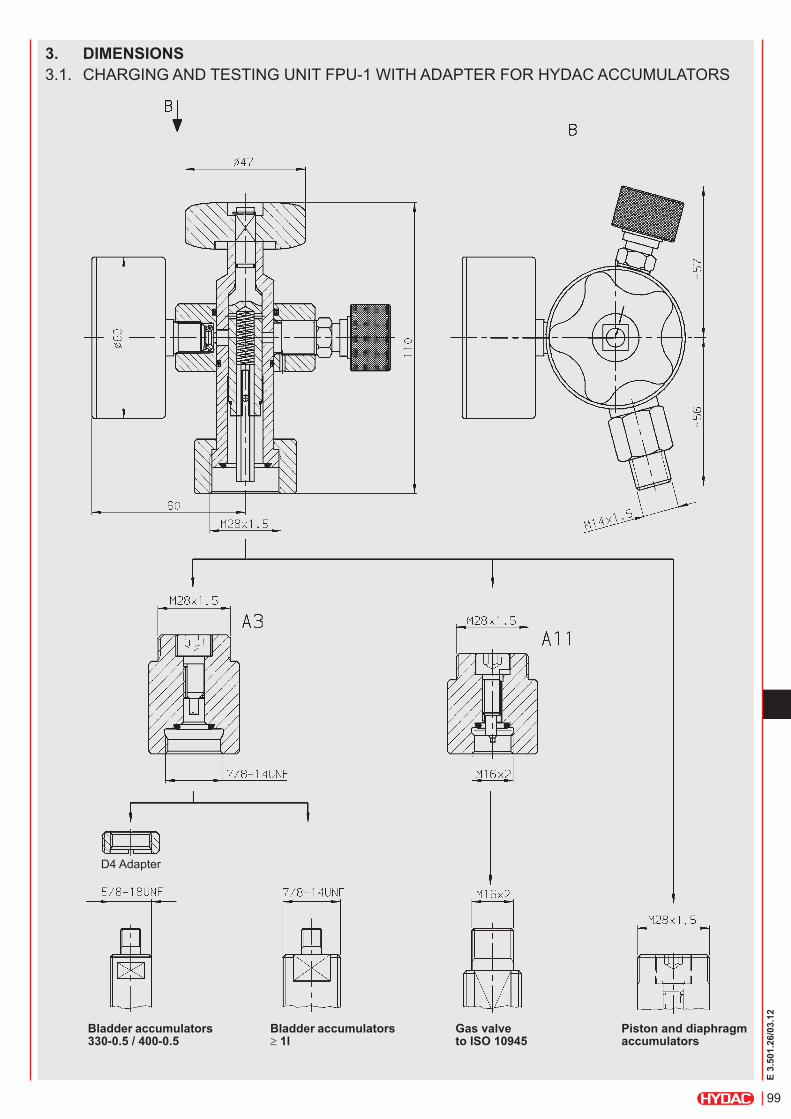
3. DiMensions3.1. cHARging AnD teSting unit FPu-1 WitH ADAPteR FoR HYDAc AccumulAtoRS
Bladder accumulators 330-0.5 / 400-0.5
Bladder accumulators ≥ 1l
Gas valve to iso 10945
piston and diaphragm accumulators
D4 Adapter

100
E 3.
501.
26/0
3.12
3.2. cHARging HoSe f (200 bar nitrogen bottle - connection to Din 477, Part 1)
length part no. 2.5 m 236514 4.0 m 23651510.0 m 37340515.0 m 211555220.0 m 210976528.0 m 2109574
3.3. cHARging HoSe fM (300 bar nitrogen bottle - connection to Din 477, Part 5 up to April 2002)
length part no. 2.5 m 3019417 4.0 m 3019418
3.4. cHARging HoSe fW (300 bar nitrogen bottle - connection to Din 477, Part 5 after April 2002)
length part no. 2.5 m 3019419 4.0 m 3019420
charging hoses are suitable for the particular maximum permitted operating pressure marked on them and 10,000 charging processes. (hYDac charging hoses comply with the ec Machinery Directive and with Din en 982 and Din en 853 to 857)
knurl
101
E 3.
501.
26/0
3.12
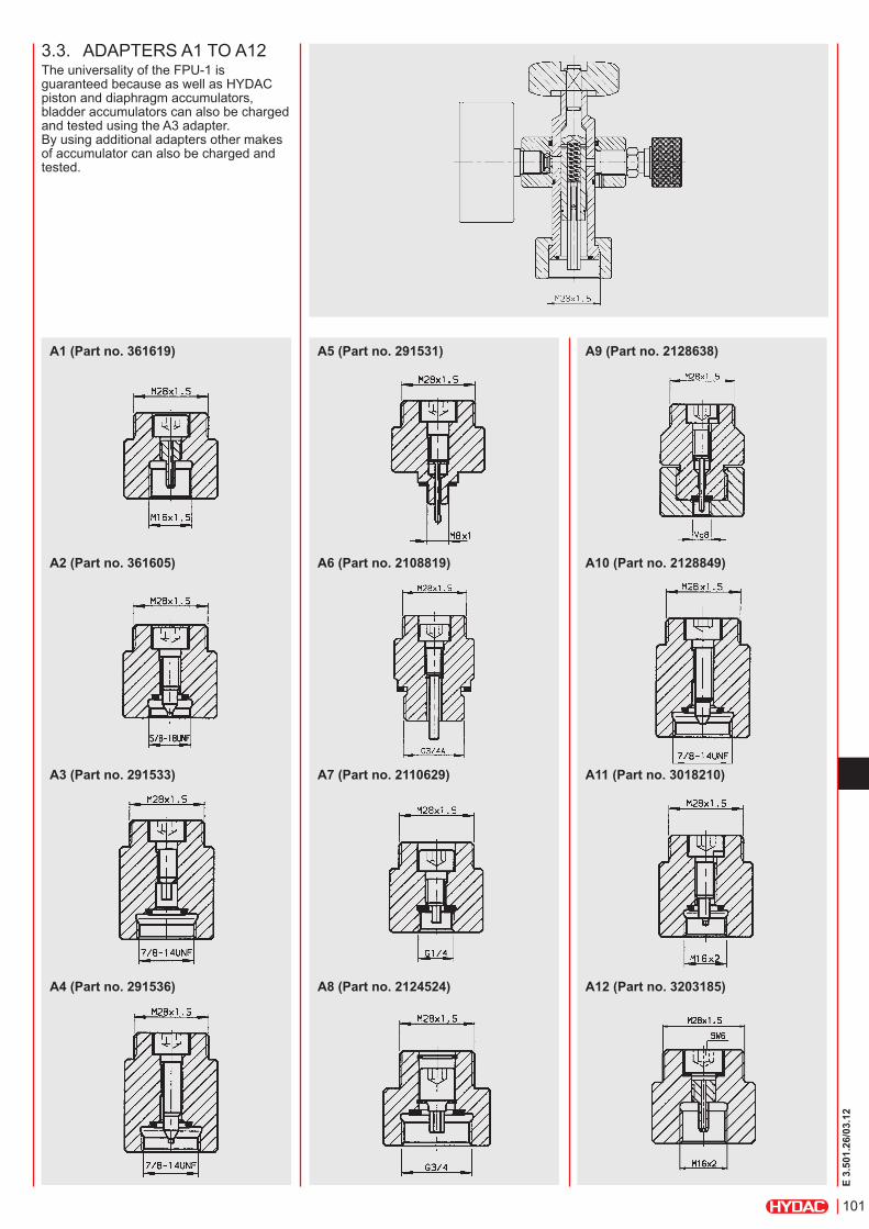
a1 (part no. 361619)
a2 (part no. 361605)
a3 (part no. 291533)
a4 (part no. 291536)
a5 (part no. 291531)
a6 (part no. 2108819)
a7 (part no. 2110629)
a8 (part no. 2124524)
a9 (part no. 2128638)
a10 (part no. 2128849)
a11 (part no. 3018210)
a12 (part no. 3203185)
3.3. ADAPteRS A1 to A12the universality of the FPu-1 is guaranteed because as well as HYDAc piston and diaphragm accumulators, bladder accumulators can also be charged and tested using the A3 adapter. By using additional adapters other makes of accumulator can also be charged and tested.
102
E 3.
501.
26/0
3.12
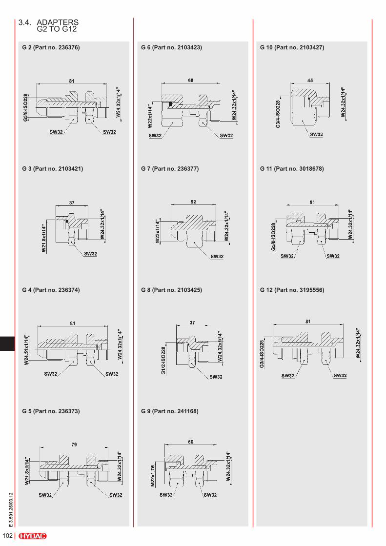
G 10 (part no. 2103427)
G 11 (part no. 3018678)
G 12 (part no. 3195556)
G 6 (part no. 2103423)
G 7 (part no. 236377)
G 8 (part no. 2103425)
G 9 (part no. 241168)
G 2 (part no. 236376)
G 3 (part no. 2103421)
G 4 (part no. 236374)
G 5 (part no. 236373)
3.4. ADAPteRS g2 to g12

103
E 3.
501.
26/0
3.12
3.4.1 schedule of countriesg adapters for nitrogen bottles from different countries.country type / Part no.
g1 1) g2 g3 g4 g5 g6 g7 g8 g9 g10 g11 g12236376 2103421 236374 236373 2103423 236377 2103425 241168 2103427 3018678 3195556
Albania zAlgeria zArgentina zAustralia zAustria zBahamas zBahrain zBangladesh zBarbados zBelgium zBolivia zBotswana zBrazil zBulgaria zBurma zcanada zchile zchina zcolumbia zcosta Rica zcyprus zczech Republic zDenmark zDjibouti zDominican Republic zecuador zegypt zethiopia zFiji zFinland zFrance zgabon zgambia zgermany zghana zgreat Britain zgreece zguatemala zguinea zguyana zHonduras zHong Kong zHungary zindia zindonesia ziran ziraq zireland zisrael zitaly zivory coast zJamaica zJapan zJordan zKenya zKorea zKuwait zlebanon zlibya zmalawi zmalaysia zmalta zmauritius zmexico zmorocco zmozambique znetherlands znew Zealand znigeria znorway zoman zPakistan zParaguay zPeru zPhilippines zPoland zPortugal zPuerto Rico zQatar zRomania zRussia zSaudi Arabia zSingapore zSouth Africa zSpain z zSri lanka zSudan zSurinam zSwaziland zSweden zSwitzerland zSyria ztaiwan ztanzania zthailand ztrinidad/tobago ztunisia zturkey zunited Arab emirates zuruguay zuSA zVenezuela zVietnam zYugoslavia 2) zZambia zz = suggestion 1) = already fitted to hose 2) = Bosnia, Herzegovina, croatia, macedonia, Slovenia
104
E 3.
501.
26/0
3.12
4. accessories4.1. PRotectiVe cASeFor storing the charging and testing unit and adapters.Different types of case are available, depending on customer requirement.FPu-1, standard model, without case: approx. 1.4 kgFPu-1, standard model, with case: approx. 3.0 kg
4.2. gAS SAFetY VAlVeProvides protection by reducing the pressure in a controlled way if pressure exceeds the permitted level unexpectedly, see catalogue section:
zSafety equipment for Hydraulic Accumulators no. 3.552
4.3. ADAPteR D4For screw connector D on bladder accumulators < 1 l (see Point 3.)
4.5. PReSSuRe ReDuceRFor adjusting the required pre-charge pressure between the nitrogen bottle and the accumulator.4.5.1 pressure reducer for 200 bar nitrogen bottlesinlet: connection W24.32x1/12-Din 477, Part 1outlet: male thread W24.32x1/14-Din 477, Part 1
Bottle pressure [bar] Pressure after reducer [bar] Part no.200 20 635409200 100 635411200 200 635412
4.5.2 pressure reducer for 300 bar nitrogen bottlesinlet: connection W30x2-Din 477, Part 5outlet: male thread W24, 32x1/14-Din 477, Part 5
Bottle pressure [bar] Pressure after reducer [bar] Part no.300 20 6004020300 100 6004021300 200 6004022300 270* 6004023
* if pressure after reducer > 200 bar, the outlet has a male thread W30x2-Din 477, Part 5
Weight: 0.5 kg
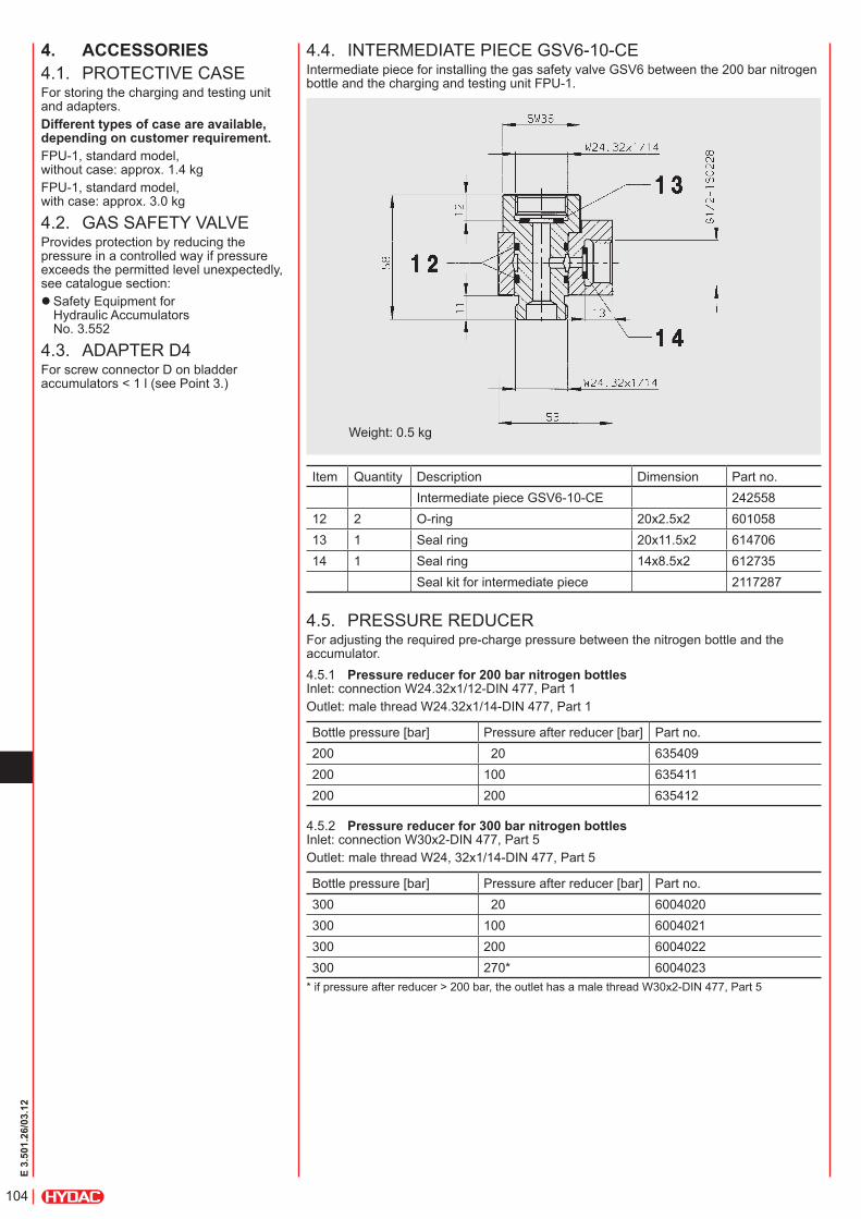
4.4. inteRmeDiAte Piece gSV6-10-ceintermediate piece for installing the gas safety valve gSV6 between the 200 bar nitrogen bottle and the charging and testing unit FPu-1.
item Quantity Description Dimension Part no.intermediate piece gSV6-10-ce 242558
12 2 o-ring 20x2.5x2 60105813 1 Seal ring 20x11.5x2 61470614 1 Seal ring 14x8.5x2 612735
Seal kit for intermediate piece 2117287

105
E 3.
501.
26/0
3.12
6. notethe information in this brochure relates to the operating conditions and applications described.For applications and operating conditions not described, please contact the relevant technical department.Subject to technical modifications.
5. spare parts, aDapters anD tools5.1. SPARe PARtScHARging AnD teSting unit FPu-1item Quantity Description Part no. 1 1 o-ring 6x1 601032 2 1 Seal ring 612730 3 1 Pressure gauge 0 - 10 bar
0 - 25 bar0 - 100 bar0 - 250 bar0 - 400 bar
635139635140635141635142635143
5 1 o-ring 15x2 601049 6 1 Seal ring 601456 7 1 o-ring 11x2 601043 8 1 o-ring 9x2 601040 9 1 o-ring 11x2.5 60368110 1 o-ring 5.7x1.9 6004009
Seal kit FPu-1 2117669
5.2. ADAPteRSDescription Part no.Seal kit for adapters A1-12 3269153
5.3. toolSDescription Part no.Wrench 14x15 1011065Allen key SW6 1005164torque wrench 3136470Valve tool for gas valve 616886
hYDac technology Gmbh industriegebiet 66280 sulzbach/saar, Germany tel.: +49 (0) 68 97 / 509 - 01 Fax: +49 (0) 68 97 / 509 - 464 internet: www.hydac.com e-mail: [email protected]

106
E 3.
501.
26/0
3.12

129
E 3.
552.
2/03
.12
Safety Equipment for Hydraulic Accumulators
1. DESCRIPTION1.1. GeneralHydraulic accumulators are pressure vessels, as defined by PED 97/23/EC, and as such their manufacture is subject to the statutory pressure equipment regulations.For safety in the workplace, system manufacturers and operators must draw up a risk assessment for the particular site.These must take into account possible risks at the installation site, particularly in combination with external factors.Fundamental risks affecting hydraulic accumulators are:
zExcessive pressure and z Temperature increase (e.g. in the event of an external fire).
HYDAC provides the appropriate safety equipment to protect accumulators from excessive values on the gas and fluid side; see also catalogue section:
zaccumulators No. 3.000
2. PROTECTION ON THE GAS SIDE
2.1. TEMPERATURE FUSEHYDAC offers two different kinds of temperature fuse.In addition to the proven temperature fuse in carbon steel and stainless steel, HYDAC also offers a temperature fuse of the type GMP6, which is approved according to PED 97/23/EC.It is made of stainless steel and has a CE mark.
2.1.1 Mode of operationTemperature fuses are "devices with a safety function" and are used to release the gas pressure by discharging the nitrogen completely when a rise in temperature reaches unacceptable levels (e.g. in the case of fire).
Technical specifications Permitted operating pressure: ≤ 450 barTemperature range: -10 °C ... +80 °CMelting point: between +160 °C and +170 °C
Technical specifications Permitted operating pressure: 50 ... 350 barTemperature range: -40 °C ... +80 °CMelting point: between +160 °C and +180 °C
2.1.3 Preferred modelsPart no. Description363501 Temperature fuse
7/8-14UNF 3114417 Temperature fuse
7/8-14UNF with crane hook
3517438 GMP6-10-CE1637... for piston accumulators
3521196 GMP6-10-CE1637... for bladder and diaphragm accumulators
2.1.4 Installing the temperature fuseSimple to retrofit by replacing the sealing cap with the temperature fuse.
Gas side of the accumulator shown with temperature fuse
Installing the temperature fuse GMP6 Please read the Operating Manual! z GSV/GMP No. 3.504.CE
Gas side of the accumulator shown with sealing cap
Housing
Housing
Discharge opening
Discharge opening
Screw-on thread
Screw-in thread
2.1.2 Design / Technical specifications
Temperature fuse design
Temperature fuse GMP6 design
130
E 3.
552.
2/03
.12
2.2. BURSTING DISC2.2.1 DesignProtection by discharging the nitrogen completely when the pressure exceeds the permitted level.
2.2.2 FunctionIf the pressure exceeds the permitted level, the bursting disc shatters, permanently opening the port. This reduces the gas pressure by discharging the nitrogen completely.Bursting discs are designed for different burst pressures and are supplied with a certificate of conformity. Bursting discs are made either entirely of stainless steel, or from an alloy based on stainless steel and nickel.2.2.3 Preferred modelsPart no. 1) Description Burst
pressure ± 10% at 50 °C
3156148 Bursting disc plug 1/4"NPT
210 bar
3156152 Bursting disc plug 1/4"NPT
350 bar
3156155 Bursting disc plug 1/4"NPT
450 bar
1) higher pressures, different threads and burst pressure tolerances on request
2.3. GAS SAFETY VALVE2.3.1 Assembly and dimensions
steel/elastomer gasket lead-seal
hex. 32
GSV6 - 10 - 1637 EN ISO 4126-1.6.G.195 KG/H 330 BAR TS -20/80 °C PS 370 BAR 14/03/452
2.3.3 Model code (also order example)
GSV6-10 – CE1637.ENISO4126-1.6.G. 195. 330
Gas safety valve
Component code
Flow rate Q [kg/h](see table, Point 2.3.5)
Pressure setting p [bar](see table, Point 2.3.5)
2.3.2 FunctionThe gas safety valve provides protection by reducing the pressure in a controlled way if pressure exceeds the permitted level unexpectedly. It is pre-set on the pressure side and lead-sealed by the authorised representative. It is also supplied with a certificate of conformity and a type approval.
2.3.4 Technical specificationsDesign PED 97/23/EC, EN ISO4126-1, EN 13445-6, others on requestModule category IV to PED 97/23/EC Module B + D (EC prototype testing) Module G (EC individual testing) on requestNominal size 6 mmMaterial Stainless steel, closing element with flexible seat sealMedium Nitrogen (N2)Operating pressure range 30 ... 370 barTemperature range -20 °C ... +80 °CWeight 1.1 kg
Discharge opening
Screw-in thread

131
E 3.
552.
2/03
.12
Pressure range Gas safety valve
Adapter body* Part no.
adapter, complete Part no.
30- 350 bar 00363713 02103381* pmax= 400 bar
2.3.5 Preferred modelsQ [kg/h] p [bar] ± 10 % Part no. 1)
15 30 3123965 20 40 3123966 28 50 3123967 35 60 3124028 40 70 3124029 45 80 3124030 50 90 3124031 58 100 3124032 65 110 3124033 70 120 3124034 75 130 3124035 83 140 3124036 88 150 3124037 95 160 3124038100 170 3124039105 180 3124040110 190 3124041118 200 3124042125 210 3124043130 220 3124044135 230 3124045140 240 3124046148 250 3124047155 260 3124048160 270 3124049165 280 3124050170 290 3124051178 300 3124052185 310 3124053190 320 3124054195 330 3124055200 340 3124056205 350 3124057210 360 3153706216 370 3143015
1) others on request.
> 350 bar = surcharge for individual EC testing2.3.6 Installing the gas safety valve GSVThe self-centring gasket means that this valve can be installed simply and securely in any position.Please read the Operating Manual!
zGSV/GMP No. 3.504.CE
2.3.7 Adapter for gas safety valve GSV6To protect standard and low pressure bladder accumulators, the adapter shown below must be ordered with the gas safety valve GSV6.
132
E 3.
552.
2/03
.12
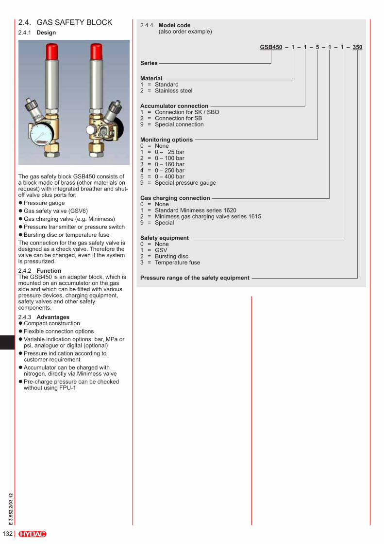
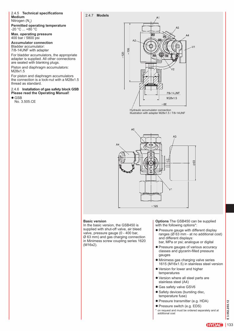
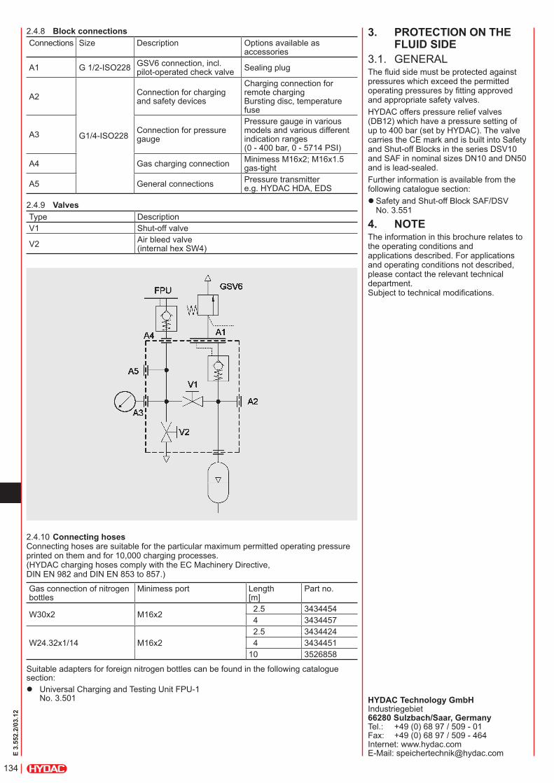
The gas safety block GSB450 consists of a block made of brass (other materials on request) with integrated breather and shut-off valve plus ports for:
zPressure gauge zGas safety valve (GSV6) zGas charging valve (e.g. Minimess) zPressure transmitter or pressure switch zBursting disc or temperature fuse
The connection for the gas safety valve is designed as a check valve. Therefore the valve can be changed, even if the system is pressurized.2.4.2 FunctionThe GSB450 is an adapter block, which is mounted on an accumulator on the gas side and which can be fitted with various pressure devices, charging equipment, safety valves and other safety components.2.4.3 Advantages
zCompact construction z Flexible connection options zVariable indication options: bar, MPa or psi, analogue or digital (optional) zPressure indication according to customer requirement zAccumulator can be charged with nitrogen, directly via Minimess valve zPre-charge pressure can be checked without using FPU-1
2.4. GAS SAFETY BLOCK2.4.1 Design
2.4.4 Model code (also order example)
GSB450 – 1 – 1 – 5 – 1 – 1 – 350
Series
Material 1 = Standard 2 = Stainless steel
Accumulator connection 1 = Connection for SK / SBO 2 = Connection for SB 9 = Special connection
Monitoring options 0 = None 1 = 0 – 25 bar 2 = 0 – 100 bar 3 = 0 – 160 bar 4 = 0 – 250 bar 5 = 0 – 400 bar 9 = Special pressure gauge
Gas charging connection 0 = None 1 = Standard Minimess series 1620 2 = Minimess gas charging valve series 1615 9 = Special
Safety equipment 0 = None 1 = GSV 2 = Bursting disc 3 = Temperature fuse
Pressure range of the safety equipment
133
E 3.
552.
2/03
.12
2.4.5 Technical specificationsMedium Nitrogen (N2)Permitted operating temperature -20 °C ... +80 °CMax. operating pressure 400 bar / 5800 psiAccumulator connection Bladder accumulator: 7/8-14UNF with adapterFor bladder accumulators, the appropriate adapter is supplied. All other connections are sealed with blanking plugs.Piston and diaphragm accumulators: M28x1.5For piston and diaphragm accumulators the connection is a lock-nut with a M28x1.5 thread as standard.2.4.6 Installation of gas safety block GSBPlease read the Operating Manual!
zGSB No. 3.505.CE
Basic version In the basic version, the GSB450 is supplied with shut-off valve, air bleed valve, pressure gauge (0 - 400 bar, Ø 63 mm) and gas charging connection in Minimess screw coupling series 1620 (M16x2).
Hydraulic accumulator connection Illustration with adapter M28x1.5 / 7/8-14UNF
Options The GSB450 can be supplied with the following options*:
zPressure gauge with different display ranges (Ø 63 mm - at no additional cost) and different displays: bar, MPa or psi; analogue or digital zPressure gauges of various accuracy classes and glycerin-filled pressure gauges zMinimess gas charging valve series 1615 (M16x1.5) in stainless steel version zVersion for lower and higher temperatures zVersion where all steel parts are stainless steel (A4) zGas safety valve GSV6 zSafety devices (bursting disc, temperature fuse) zPressure transmitter (e.g. HDA) zPressure switch (e.g. EDS)
* on request and must be ordered separately and at additional cost
2.4.7 Models
134
E 3.
552.
2/03
.12
2.4.8 Block connectionsConnections Size Description Options available as
accessories
a1 G 1/2-ISO228 GSV6 connection, incl. pilot-operated check valve Sealing plug
a2
G1/4-ISO228
Connection for charging and safety devices
Charging connection for remote charging Bursting disc, temperature fuse
A3 Connection for pressure gauge
Pressure gauge in various models and various different indication ranges (0 - 400 bar, 0 - 5714 PSI)
a4 Gas charging connection Minimess M16x2; M16x1.5 gas-tight
a5 General connections Pressure transmitter e.g. HYDAC HDA, EDS
2.4.9 ValvesType DescriptionV1 Shut-off valve
V2 Air bleed valve (internal hex SW4)
3. PROTECTION ON THE FLUID SIDE
3.1. GENERALThe fluid side must be protected against pressures which exceed the permitted operating pressures by fitting approved and appropriate safety valves.HYDAC offers pressure relief valves (DB12) which have a pressure setting of up to 400 bar (set by HYDAC). The valve carries the CE mark and is built into Safety and Shut-off Blocks in the series DSV10 and SAF in nominal sizes DN10 and DN50 and is lead-sealed.Further information is available from the following catalogue section:
zSafety and Shut-off Block SAF/DSV No. 3.551
4. NOTEThe information in this brochure relates to the operating conditions and applications described. For applications and operating conditions not described, please contact the relevant technical department. Subject to technical modifications.
HYDAC Technology GmbH Industriegebiet 66280 Sulzbach/Saar, Germany Tel.: +49 (0) 68 97 / 509 - 01 Fax: +49 (0) 68 97 / 509 - 464 Internet: www.hydac.com E-Mail: [email protected]
2.4.10 Connecting hosesConnecting hoses are suitable for the particular maximum permitted operating pressure printed on them and for 10,000 charging processes. (HYDAC charging hoses comply with the EC Machinery Directive, DIN EN 982 and DIN EN 853 to 857.)
Gas connection of nitrogen bottles
Minimess port Length [m]
Part no.
W30x2 M16x2 2.5 3434454 4 3434457
W24.32x1/14 M16x2 2.5 3434424 4 343445110 3526858
Suitable adapters for foreign nitrogen bottles can be found in the following catalogue section: z Universal Charging and Testing Unit FPU-1 No. 3.501

E 3.
502.
24/1
1.13
251
1. Description1.1. GeneralHYDaC supports are used to mount all types of hydraulic accumulator safely and simply. Clamps, consoles and complete accumulator sets are available.
1.2. UseThe supports are designed for static use. For dynamic stresses, specially designed clamps are available on request.
2. selection tables for supports
2.1. BlaDDer aCCUMUlaTOr
Supports for Hydraulic Accumulators
1 Clamp2 Console3 rubber support ring4 Back plate
Description
Capacity [l]
sB
330
sB
400
sB
550
sB
500
/ s
B60
0s
B35
sB
40
sB
35H
sB
35H
B
sn
1 2.5+
54+
610
-24
32-5
00.
54 10
-20
32-5
01 2.
5-5
10-2
032
-50
2.5-
510
-20
32-5
02.
5-5
10-2
032
-50
20 32-5
020 32
-50
50
Clamps *
Hyrac 89-92 193 sT 1
Hyrac 106-114/115 H3 sT 2 2
Hyrac 110-118/124 H10 sT 1 2
Hyrac 121-129/133 H8 sT 1 2
Hyrac 167-175/178 H5 sT 1 1
Hyrac 202-210/214 H8 sT 1 2 1 2
Hyrac 216-224/226 H5 sT 1 2 1 2
Hyrac 223-230/231 H3 sT 1 2 2
Hyrac 225-234/234 H3 sT 1 2
Hss 242 1 2
Consoles
KBK 167 / G 1 1
KBK 222 / G 1 1 1 1 1 1 1 1 1 1 1
KHF 210 / G 1 1 1 1
accumulator set
seB 1 1 1 1 1 1 1
seH 1 1 1
sen 1 1 1
seM 1 1 1
seHF 1 1
seHB 1 1* The number of clamps can vary depending on the requirements and on the length of the accumulator. These are recommendations.
1
32
4

E 3.
502.
24/1
1.13
252
1 Clamp2 Console3 Back plate
2.2. PisTOn aCCUMUlaTOr
Type
Piston diameter [mm]50 60 80 100 150 180 250 > 250
accumulator external diameter [mm]60 70 95 100 120 125 180 210 220 286 300 > 300
Clamps sK280 *HrGKsM 0 r 58-61/62 sT
On
requ
est
HrGKsM 0 r 70-73/73 sT HrGKsM 0 r 92-95/96 sT HrGKsM 1 r 119-127/124 sT Clamps sK standard *Hyrac 96-100/100 sT
on
requ
est
Hyrac 121-129/133 H8 sT Hyrac 176-185/187 H5 sT Hyrac 209-217/223 H10 sT Hyrac 216-224/226 H5 sT Hss 286 Hss 310 consolesKBK 126 1
On
requ
est
KBK 219 1 1KBK 310 1 1* selecting the correct clamp depends on the external diameter of the accumulator. Depending on the application and length of the accumulator, we recommend that several clamps are used. Clamps must be mounted near the end caps in order to prevent deformation of the cylinder.
2.3. DiaPHraGM aCCUMUlaTOr (WelD TYPe)
1 Clamp
1
2.4. DiaPHraGM aCCUMUlaTOr (sCreW TYPe)
1 Console
1
accumulator type Clamp typesBO250-0.075e Hyrac 62-65/65 sTsBO210-0.16e Hyrac 73-76/76 sTsBO210-0.32e Hyrac 92-95/96 sTsBO210-0.5e Hyrac 100-105/106 H3 sTsBO100-0.7e Hyrac 106-114/115 H3 sTsBO330-0.6e
Hyrac 110-118/124 H10 sTsBO330-0.7esBO210-0.75e
Hyrac 121-129/133 H8 sTsBO330-0.75esBO200-1e Hyrac 133-142/142 H3 sTsBO140-1.4e
Hyrac 143-151/151 H3 sTsBO210-1.4esBO330-1.4e Hyrac 152-159/160 H3 sTsBO100-2e Hyrac 160-167/169 H5 sTsBO210-2e
Hyrac 167-175/178 H5 sT
sBO210-2.8esBO250-3.5esBO330-2esBO330-2.8esBO330-3.5e
Type of accumulator ConsolesBO210-1.3a6 KMs 200sBO400-1.3a6 KMs 210sBO100-2.0a6
KMs 220sBO250-2.0a6sBO210-2.8a6 KMs 250sBO400-2.8a6 KMs 280sBO210-4.0a6 KMs 300sBO400-4.0a6 KMs 310
1
2
3

E 3.
502.
24/1
1.13
253
3. claMps
Hyrac ( ØD ≤ 100 mm ) Hyrac ( ØD ≥ 100 mm )
Closing device, support zinc-platedClamping band stainless steelinsert Pe
Closing device, support zinc-platedClamping band stainless steelinsert Pe, nBr
Description Part no. a B C max ØD (from - to) H (from - to)[mm]
e l s K max. Weight:
[mm] [mm] [mm] [mm] [mm] [mm] [mm] [mm] [kg]HrGKsM 0 r 58-61/62 sT 3018442
120 8583 58 - 61 37.3 - 38.8
40 63 –
0.16HrGKsM 0 r 70-73/73 sT 3018444 93 70 - 73 42.0 - 43.5 0.21HrGKsM 0 r 92-95/96 sT 444995 115 92 - 95 52.5 - 54.0 0.24HrGKsM 1 r 119-127/124 sT 444505 158 100 154 119 - 127 66.8 - 70.8 50 18 0.36Hyrac 62-65/65 sT 445037
120 85
85 62 - 65 38 - 39.5
40 6 3 –
0.16Hyrac 73-76/76 sT 445038 96 73 - 76 43.5 - 45 0.16Hyrac 89-92/92 sT 445039 112 89 - 92 51 - 52.5 0.17Hyrac 92-95/96 sT 445040 115 92 - 95 52.5 - 54 0.17Hyrac 96-100/100 sT 445041 120 96 - 100 54.5 - 56.5 0.17Hyrac 100-105/106 H3 sT 444904
156 100
135 100 - 105 59 - 62
60 18 3 –
0.40Hyrac 106-114/115 H3 sT 444905 143 106 - 114 62.5 - 66 0.41Hyrac 110-118/124 H10 sT 445042 156 110 - 118 72.5 - 77 0.42Hyrac 121-129/133 H8 sT 444906 165 121 - 129 75.5 - 80 0.43Hyrac 133-142/142 H3 sT 444907 174 133 - 142 76.5 - 82.5 0.44Hyrac 143-151/151 H3 sT 444908 182 143 - 151 83 - 86.5 0.45Hyrac 152-159/160 H3 sT 444909 191 152 - 159 87 - 91 0.46Hyrac 160-167/169 H5 sT 444910
236 152
197 160 - 167 89 - 92
60 32 4 –
0.70Hyrac 167-175/178 H5 sT 445043 207 167 - 175 92.5 - 96.5 0.72Hyrac 176-185/187 H5 sT 445044 241 176 - 185 97 - 102.5 0.75Hyrac 202-210/214 H8 sT 445045 245 202 - 210 116 - 120 0.76Hyrac 209-217/223 H10 sT 445046 255 209 - 217 122.5 - 126.5 0.77Hyrac 216-224/226 H5 sT 445047 256 216 - 224 120 - 124 0.77Hyrac 223-230/231 H3 sT 445048 259 223 - 230 120.5 - 123.5 0.78Hyrac 225-234/234 H3 sT 445049 265 225 - 234 123 - 127.5 0.79
Model/order code (example): Hyrac 167-175/178 H5 sT 445043
HrGKsM
Closing device, support zinc-platedClamping band stainless steelinsert lDPe

E 3.
502.
24/1
1.13
254
Hss
Clamp zinc-plated
insert nBr
Description Part no. a B C max ØD (from - to) H (from - to) e l s K max. Weight:
[mm] [mm] [mm] [mm] [mm] [mm] [mm] [mm] [mm] [kg]Hss 222/229 235224 268 216 244 222 - 229 123
40 Ø15 4
292 1.60Hss 242 362712 267 216 267 242 136 306 1.66Hss 286 237395 330 280 314 286 163 355 1.95Hss 310 237389 330 280 333 310 170 390 2.45Hss 360 355592 426 365 383 360 195 434 2.56
Model/order code (example): Hss 222/229 235224

E 3.
502.
24/1
1.13
255
4. consoles4.1. COnsOle KBK FOr BlaDDer anD PisTOn aCCUMUlaTOr
Console KBK rubber support ring G
G 167
G 222
G 360
4.2. KMs COnsOles FOr DiaPHraGM aCCUMUlaTOr sCreW TYPe
The screw type diaphragm accumulator has threaded bores M8 in the lock nut for fixing to the KMS console.
*
* Ø22 on KBK 310 and KBK 360
Type Mat. Part no. a B C ØD e F G H Weight:
[mm] [mm] [mm] [mm] [mm] [mm] [mm] [mm] [kg]126
sTZn
290530 175 100 60 65 36 – 150 77 1.1167 238526 260 200
100120 75 35 225 92 2.5
219 238042 270 180 135 80 40 250123
6.5222 3002160 260 200 170 75 35 225 2.4310 238043 330 220 200 190 140
60340 170 18.3
360 357959 390 270 240 211 180 390 195 20.1
Model/order code (example):KBK 167 sTZn 238526
Type Material Part no.
–
nBr
–167 236997– –222 236996– –360 355966
G 167 nBr 236997
Type Mat. Part no. a B C ØD ØP e F G H Øi Weight:[mm] [mm] [mm] [mm] [mm] [mm] [mm] [mm] [mm] [mm] [kg]
200
sTZn
359931 270 180
100
148 160 80 40 250
123 14
6.5210 358989
260 200170 180
75 35 225 2.4220 359922 170 188250 359924 192 204280 359925
330 220 200
215 230
140 60 340 170 22 18.3300 359926 220 235310 359927 245 265320 359928 290 305
Model/order code (example):KMs 200 sTZn 359931

E 3.
502.
24/1
1.13
256
seB, seH, seM 5.1. seB FOr sB330/440accum- ulator set
Part no. Vol. a B C D e F G H l J
[l] [ mm] [mm] [mm] [mm] [mm] [mm] [mm] [mm] [mm] [mm]seB 2.5 290787 2.5 460 310 198 138 132 214 200 400 75 –
seB 4 238403 4 410 320 330 270152 253
–
270 45 95
seB 6 2115851 6
570 420
330 270
330
75 111
seB 10 238407 10
180 317
330
seB 20 240598 20 500
seB 32 238409 321340 1190 500 1160
seB 50 240599 50This accumulator set seB is also available with a saF and sB330 as a compact unit (aCCUseT sB330). see catalogue section:
aCCUseT sB no. 3.503
5.2. seH FOr sB500/550/600accum- ulator set
Part no. Vol. a B C D e F G H l J
[l][ mm] [mm] [mm] [mm] [mm] [mm] [mm] [mm] [mm] [mm]
seH 2.5 2105194 2.5 460 310198 138 133.5 223 200
400
75
–seH 5 2105195 5 750 600 650
seH 10 378952 10 570 420
330 270 194 323
– 330
111seH 20 298181 20 500
seH 32 298182 321340 1190 500 1160
seH 50 298183 50
5.3. seM FOr sB40accum- ulator set
Part no. Vol. a B C D e F G H l J
[l][ mm] [mm] [mm] [mm] [mm] [mm] [mm] [mm] [mm] [mm]
seM 2.5 3007402 2.5 460 310198 138 121.5 201
200 410
75
–seM 5 3007423 5 750 600 220 650
seM 10 3007424 10 570 420
330 270 172 310
– 330
111seM 20 3007425 20 500
seM 32 3007426 321340 1190 500 1160
seM 50 3007427 50
5. accuMulator set for blaDDer accuMulators
E 3.
502.
24/1
1.13
257
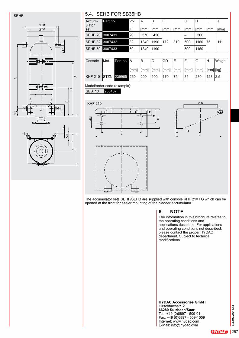
seHB 5.4. seHB FOr sB35HBaccum- ulator set
Part no. Vol. a B e F G H l J
[l] [mm] [mm] [mm] [mm] [mm] [mm] [mm] [mm]seHB 20 3007431 20 570 420
172 310
– 500
75 111seHB 32 3007432 32 1340 1190 500 1160
seHB 50 3007433 50 1340 1190 500 1160
Console Mat. Part no. a B C ØD e F G H Weight
[mm] [mm] [mm] [mm] [mm] [mm] [mm] [mm] [kg]
KHF 210 sTZn 239965 260 200 100 170 75 35 230 123 2.5
Model/order code (example):seB 10 238407
The accumulator sets seHF/seHB are supplied with console KHF 210 / G which can be opened at the front for easier mounting of the bladder accumulator.
KHF 210
6. noteThe information in this brochure relates to the operating conditions and applications described. For applications and operating conditions not described, please contact the proper HYDaC department. subject to technical modifications.
HYDac accessories GmbH Hirschbachstr. 2 66280 sulzbach/saar Tel.: +49 (0)6897 - 509-01 Fax: +49 (0)6897 - 509-1009 internet: www.hydac.com e-Mail: [email protected]

E 3.
502.
24/1
1.13
258

143
E 3.
503.
3/03
.12
ACCUSET SB
1. DescriptionThe HYDAC accumulator unit ACCUSET SB consists of a bladder accumulator SB, a safety and shut-off block SAF and the appropriate accumulator set SEB. The parts are designed for optimum compatibility and provide a compact, ready-to-install unit.This space-saving combination simplifies the connection of the accumulator to the hydraulic system, reduces maintenance costs and considerably reduces assembly costs. Advantages:
zSimple and secure mounting of the accumulator at the installation site, zConnection of the accumulator with a hydraulic system via a safety and shut-off block, zProtects the accumulator from excessive pressure, zDischarge of the accumulator to the tank via a pressure release valve, zSeparation of the accumulator from the system, z Two additional hydraulic connections on the shut-off block for accessories (e.g. pressure gauge).
1.1. STANDARD BLADDER ACCUMULATOR SB330
with a nominal volume of 1 ... 50 litres. Special accumulators available on request. See catalogue section:
zBladder Accumulators Standard No. 3.201
please read the operating Manual! no. 3.201.ce
1.2. SAFETY AND SHUT OFF BLOCK SAF
in nominal sizes 10, 20 and 32, with manual or solenoid-operated/manual discharge and with the direct-operated pressure relief valve DB12 with CE marking, in accordance with the regulations of DIN EN 14359 “Accumulators for hydraulic applications” and the European Pressure Equipment Directive PED 97/23/EC.See catalogue section:
zSafety and Shut-off Block SAF/DSV No. 3.551
1.3. ACCUMULATOR SET SEB
for mounting the bladder accumulator with clamps, back plate, console and rubber support ring.See catalogue section:
zSupports for Hydraulic Accumulators No. 3.502
2. tecHnicAL speciFicAtions
Design: Pressure Equipment Directive PED 97/23/EC 1)
permitted operating pressure: 330 bar 1)
permitted temperature range: -10 ... +80 °C (NBR) 1)
Temperatures exceeding this range (e.g. in the event of an external fire) can result in the accumulator bursting. To prevent this, HYDAC can provide additional temperature fuses and bursting discs.operating medium: Hydraulic fluids of types HL, HLP, HFA, HFB, HFC (NBR)pressure limit:
DB12 set to 330 bar 1)
release valve: Operating voltage 24 V DC 1)
Fluid connection p: See table at point 5.surface: Accumulator primed, SAF block phosphate-plated, accumulator set zinc-plated.The accumulator is supplied with 5 ... 8 bar protective storage pressure. Before commissioning, the accumulator must be pre-charged using the FPU-1. Recommendation: approx. 0.9 • pmin at tmax
See catalogue section: zAccumulators No. 3.000
For selection of gas pre-charge pressure, see Operating Manual:
zCharging and Testing Unit FPU-1 No. 3.501
1) others on request

144
E 3.
503.
3/03
.12
3. MoDeL coDe (also order example)
AccUset sB 330 – 10 A 1 / 1 1 2 U – 10 Y 1 – 330type of accumulator SB = bladder accumulator
Accumulator series
nominal volume [l]
Fluid connection A = standard connection
Gas valve 1 = standard model
Material of fluid connection / block 1 = carbon steel 2 = stainless steel
shell material 1 = carbon steel
Accumulator bladder/seal material 2 = NBR / NBR 3 = ECO / NBR 4 = IIR / EPDM 6 = FKM / FKM
Certification code
SAF block series
type of directional poppet valve M = manual discharge Y = solenoid-operated and manual discharge (open when de-energised)) Z = solenoid-operated and manual discharge (closed when de-energised)
type of voltage - directional poppet valve 1 = 24 V DC (only on Y or Z model)
permitted operating pressure/ cracking pressure of the pressure relief valve [bar]
circuit diagram
to the circuit

145
E 3.
503.
3/03
.12
4. preFerreD MoDeLs
Description Part no. SB
330-
1A1/
112U
-330
A
SB
330-
2.5A
1/11
2U-3
30A
SB
330-
4A1/
112U
-330
A
SB
330-
6A1/
112U
-330
A
SB
330-
10A
1/11
2U-3
30A
SB
330-
13A
1/11
2U-3
30A
SB
330-
20A
1/11
2U-3
30A
SB
330-
24A
1/11
2U-3
30A
SB
330-
32A
1/11
2U-3
30A
SB
330-
50A
1/11
2U-3
30A
SA
F10M
12T3
30A
SA
F10E
12Y
1T33
0A
SA
F20M
12T3
30A
SA
F20E
12Y
1T33
0A
SA
F32M
12T3
30A
SA
F32E
12Y
1T33
0A
ACCUSET SB330-1A1/112U-10M-330 3033471 z z
ACCUSET SB330-1A1/112U-10Y1-330 3033472 z z
ACCUSET SB330-2.5A1/112U-10M-330 3033473 z z
ACCUSET SB330-2.5A1/112U-10Y1-330 3033474 z z
ACCUSET SB330-4A1/112U-10M-330 3033475 z z
ACCUSET SB330-4A1/112U-10Y1-330 3033476 z z
ACCUSET SB330-6A1/112U-10M-330 3033477 z z
ACCUSET SB330-6A1/112U-10Y1-330 3033478 z z
ACCUSET SB330-10A1/112U-10M-330 3033479 z z
ACCUSET SB330-10A1/112U-10Y1-330 3033480 z z
ACCUSET SB330-13A1/112U-10M-330 3033481 z z
ACCUSET SB330-13A1/112U-10Y1-330 3033482 z z
ACCUSET SB330-13A1/112U-20M-330 3033483 z z
ACCUSET SB330-13A1/112U-20Y1-330 3033484 z z
ACCUSET SB330-20A1/112U-20M-330 3033485 z z
ACCUSET SB330-20A1/112U-20Y1-330 3033486 z z
ACCUSET SB330-24A1/112U-20M-330 3033487 z z
ACCUSET SB330-24A1/112U-20Y1-330 3033488 z z
ACCUSET SB330-32A1/112U-20M-330 3033489 z z
ACCUSET SB330-32A1/112U-20Y1-330 3033490 z z
ACCUSET SB330-32A1/112U-32M-330 3033491 z z
ACCUSET SB330-32A1/112U-32Y1-330 3033492 z z
ACCUSET SB330-50A1/112U-20M-330 3033493 z z
ACCUSET SB330-50A1/112U-20Y1-330 3033494 z z
ACCUSET SB330-50A1/112U-32M-330 3033495 z z
ACCUSET SB330-50A1/112U-32Y1-330 3033496 z z
Other combinations and models available on request.

146
E 3.
503.
3/03
.12
5. DiMensionsDescription ItemAccumulator shell 1Gas valve 2Oil valve 3Adapter S 4Switching handle 5Release spindle 6SAF safety block 7Pressure relief valve 8Connection for pressure gauge 9Release valve 10Console 11HyRac clamp 12Back plate 13
Bladder accumulator
Amax [mm]
B [mm]
C [mm]
ØDmax [mm]
E [mm]
F [mm]
I [mm]
G [mm]
H [mm]
SB330-1 1) 302 – –118
– – – – –SB330-2.5 2) 532 460 310 133 214 75 198 138SB330-4 410 410 320
173 152 26545
330 270
SB330-6 540
570 42075
SB330-10 568
229 180 317
SB330-13 660SB330-20 896SB330-24 1062SB330-32 1411
1340 1190SB330-50 1931
1) without back plate and console, with a HyRac clamp 110-118/124 H10 ST 2) without console, with back plate and two HyRac clamps 110-110/124 H10 ST
SAF series Nominal size SB330 [l]
P ISO 228
Connection for pressure gauge
J [mm]
SAF101
G 1/2 2 x G 1/4142
2.5 ... 6 143≥ 10 147
SAF201
G 1G 1/4, G 1/2
1732.5 ... 6 174≥ 10 178
SAF32 ≥ 1 G 1 1/2 203
6. noteThe information in this brochure relates to the operating conditions and applications described. For applications and operating conditions not described, please contact the relevant technical department. Subject to technical modifications.
HYDAC Technology GmbH Industriegebiet 66280 Sulzbach/Saar, Germany Tel.: +49 (0) 68 97 / 509 - 01 Fax: +49 (0) 68 97 / 509 - 464 Internet: www.hydac.com E-Mail: [email protected]
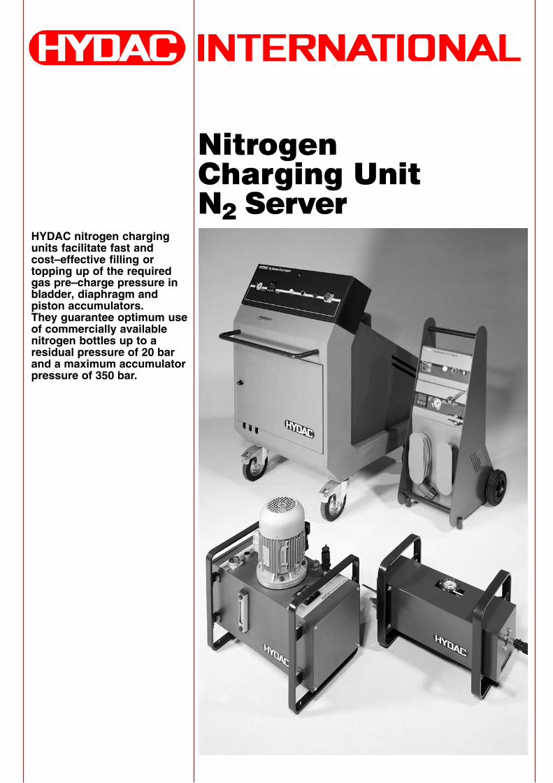
������������� ��� ��
�������������
HYDAC nitrogen chargingunits facilitate fast andcost–effective filling ortopping up of the requiredgas pre–charge pressure inbladder, diaphragm andpiston accumulators. They guarantee optimum useof commercially availablenitrogen bottles up to aresidual pressure of 20 barand a maximum accumulatorpressure of 350 bar.

A) DESCRIPTIONDepending on the model, N2 Server nitrogen charging unitsare suitable for charging smallaccumulators, and forpre–charging or topping upaccumulator stations.A piston accumulator is installedas the nitrogen pump.N2 Server nitrogen charging unitsare equipped with a pressuresafety valve which complies withPressure Equipment Directive97/23/EC.
B) TYPES OF N2 SERVER1. N2S–M
Nitrogen charging unit N2 Server Mobile
2. N2S–TPortable nitrogen charging unitN2 Server, without oil supply unit
3. N2S–VPortable nitrogen charging unitN2 Server, with oil supply unit
4. N2S–FMobile nitrogen charging unit N2 Server
5. N2S–SStationary nitrogen charging unit N2 Server
C) SAFETY INFORMATIONWhen charging hydraulicaccumulators or accumulatorsystems, if the permissibleoperating pressure of theaccumulator system is lower thanthe pressure in the nitrogenbottles used for filling, a pressurereducer valve must be connectedto the gas bottle and must beadjusted to the requiredpre–charge pressure.(Please also refer to brochure no.3.501, Charging and Testing UnitFPU–1)Hydraulic accumulators must onlybe filled with nitrogen N2(oxygen–free), and not withoxygen or air.Danger of explosion!
D) COMMISSIONINGIn accordance with the operatinginstructions supplied with the unit.
E) NOTEThe information in this brochurerelates to the operating conditionsand applications described. Forapplications or operatingconditions not described, pleasecontact the relevant technicaldepartment. Subject to technicalmodifications.
2

1.3. DIMENSIONS
N2 outletN2 intlet
approx. 510
appr
ox. 1
100
approx. 570
N2–Server N2S–M
1. NITROGEN CHARGINGUNIT N2 SERVER MOBILE N2S–M
1.1. DESCRIPTIONThe nitrogen charging unit N2 Server N2S–M is suitable forcharging small accumulators orfor topping up the gas pre–chargepressure in large accumulatorstations. It consists of an oil supply unit,the electrical and hydrauliccontrols, the piston accumulatorand the connection hoses.The hydraulic and electricaloperating controls are groupedtogether ergonomically on thefront panel.The nitrogen charging unit N2Server N2S–M is extremelycompact and can be movedeasily by one person.
1.2. TECHNICAL SPECIFICATIONSGeneral:Total weight of the unit when full:approx. 98 kgAmbient temperature:–15 °C to +50 °CHydraulic details:Operating pressure of hydraulicfluid: 320 bar max.Pressure gauge indication range:0 – 400 barFlow rate: 0.9 l/minTank size: approx. 8 lHose connection:– bottle side: W 24.32 x 1/14”– accumulator side: cap screwM 14 x 1.5 DIN 2353Hose length: – bottle side: 4 m – accumulator side: 3mCapacity of piston accumulator: 1 lElectrical details:Three–phase motor:230/400 V – 50 HZOutput: 0.75 kWSafety type: IP 55Electrical connection: CEE plug,5–pole, 16 Amp for 400 V Cable length: 5 m
Other voltages on request.
3
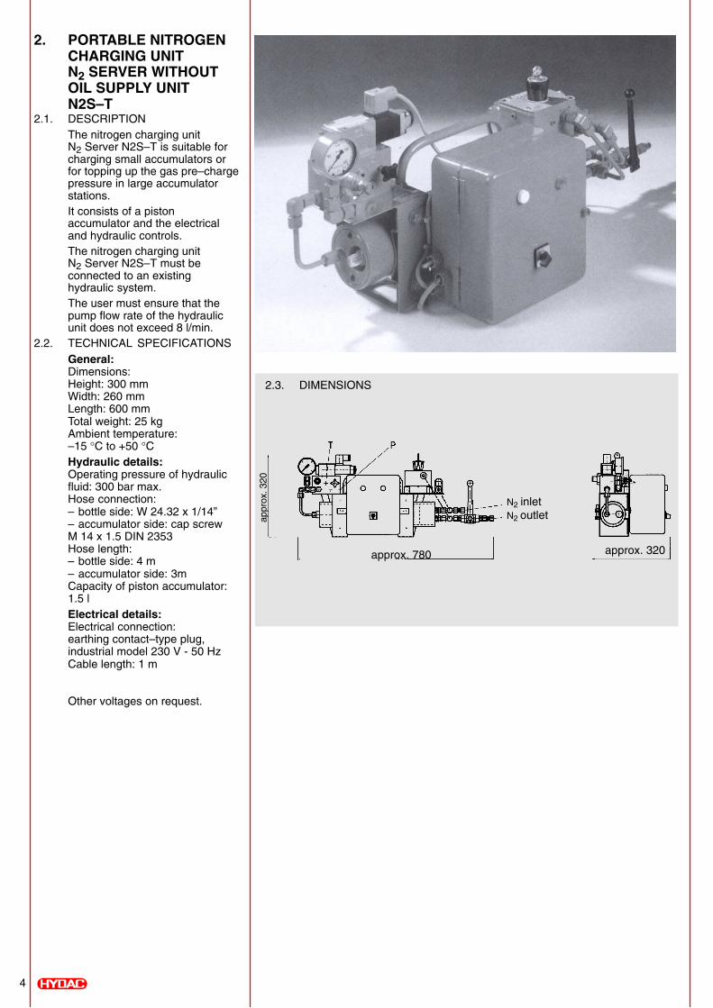
2.3. DIMENSIONS
N2 inletN2 outlet
approx. 780 approx. 320
appr
ox. 3
20
2. PORTABLE NITROGENCHARGING UNIT N2 SERVER WITHOUTOIL SUPPLY UNIT N2S–T
2.1. DESCRIPTIONThe nitrogen charging unit N2 Server N2S–T is suitable forcharging small accumulators orfor topping up the gas pre–chargepressure in large accumulatorstations. It consists of a pistonaccumulator and the electricaland hydraulic controls.The nitrogen charging unit N2 Server N2S–T must beconnected to an existinghydraulic system.The user must ensure that thepump flow rate of the hydraulicunit does not exceed 8 l/min.
2.2. TECHNICAL SPECIFICATIONSGeneral:Dimensions:Height: 300 mmWidth: 260 mmLength: 600 mmTotal weight: 25 kgAmbient temperature:–15 °C to +50 °CHydraulic details:Operating pressure of hydraulicfluid: 300 bar max.Hose connection:– bottle side: W 24.32 x 1/14”– accumulator side: cap screwM 14 x 1.5 DIN 2353Hose length: – bottle side: 4 m – accumulator side: 3mCapacity of piston accumulator:1.5 lElectrical details:Electrical connection: earthing contact–type plug,industrial model 230 V - 50 HzCable length: 1 m
Other voltages on request.
4
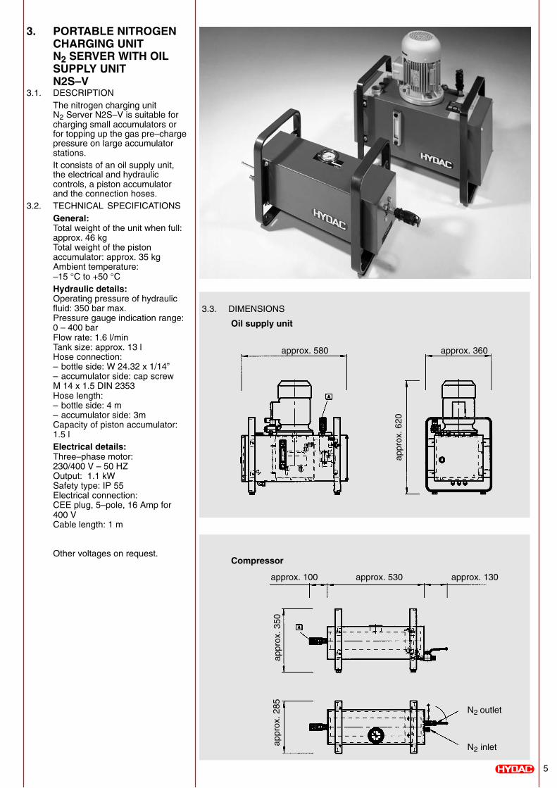
3.3. DIMENSIONS
Compressor
Oil supply unit
approx. 580 approx. 360
approx. 100 approx. 530 approx. 130
N2 outlet
N2 inlet
appr
ox. 6
20
appr
ox. 3
50ap
prox
. 285
3. PORTABLE NITROGENCHARGING UNIT N2 SERVER WITH OIL SUPPLY UNIT N2S–V
3.1. DESCRIPTIONThe nitrogen charging unit N2 Server N2S–V is suitable forcharging small accumulators orfor topping up the gas pre–chargepressure on large accumulatorstations.It consists of an oil supply unit,the electrical and hydrauliccontrols, a piston accumulatorand the connection hoses.
3.2. TECHNICAL SPECIFICATIONSGeneral:Total weight of the unit when full:approx. 46 kgTotal weight of the pistonaccumulator: approx. 35 kgAmbient temperature:–15 °C to +50 °CHydraulic details:Operating pressure of hydraulicfluid: 350 bar max.Pressure gauge indication range:0 – 400 barFlow rate: 1.6 l/minTank size: approx. 13 lHose connection:– bottle side: W 24.32 x 1/14”– accumulator side: cap screwM 14 x 1.5 DIN 2353Hose length: – bottle side: 4 m – accumulator side: 3mCapacity of piston accumulator:1.5 lElectrical details:Three–phase motor:230/400 V – 50 HZOutput: 1.1 kWSafety type: IP 55Electrical connection:CEE plug, 5–pole, 16 Amp for400 V Cable length: 1 m
Other voltages on request.
5

4.3. DIMENSIONS
approx. 1000
825
appr
ox. 1
400
1000
4. MOBILE NITROGENCHARGING UNIT N2 SERVER N2S–F
4.1. DESCRIPTIONThe nitrogen charging unit N2 Server N2S–F is designed forcharging large accumulatorsystems.It consists of a complete powerpack, piston accumulator,electrical controls and hoses,compactly mounted on a trolley.A charging and testing unit FPUis supplied with the server.
4.2. TECHNICAL SPECIFICATIONSGeneral:Total weight of the unit whenempty: approx. 380 kgAmbient temperature:–15 °C to +50 °CHydraulic details:Operating pressure of hydraulicfluid: 350 bar max.Pressure gauge indication range:0 – 400 barFlow rate: 8 l/minTank size: approx. 40 lHose connection:– bottle side: W 24.32 x 1/14”– accumulator side: cap screwM 14 x 1.5 DIN 2353Hose length: both 4 m Capacity of piston accumulator:2.5 lElectrical details:Three–phase motor:230/400 V – 50 HzOutput: 5.5 kWSafety type: IP 55Electrical connection: CEE plug, 5–pole, 16 Amp for400 V Cable length: 10 m
Other voltages on request.
6

5.3. DIMENSIONS
8251000
appr
ox. 1
270
5. STATIONARY NITROGENCHARGING UNIT N2 SERVER N2S–S
5.1. DESCRIPTIONThe nitrogen charging unit N2 Server N2S–S is identical tothe mobile nitrogen charging unitN2 Server N2S–F as far as thehydraulic and electrical controlsare concerned.The difference lies in theconstruction, which is intendedfor stationary applications.
5.2. TECHNICAL SPECIFICATIONSSee point 4.2.
7