SAFER LI-ION BATTERIES THROUGH BETTER THERMAL …...there is great interest in advanced thermal...
13
2017 NDIA GROUND VEHICLE SYSTEMS ENGINEERING AND TECHNOLOGY SYMPOSIUM POWER & MOBILITY (P&M) TECHNICAL SESSION AUGUST 8-10, 2017, NOVI, MICHIGAN SAFER LI-ION BATTERIES THROUGH BETTER THERMAL MANAGEMENT David Fogg, PhD Creare LLC Hanover, NH Richard Kaszeta, PhD Creare LLC Hanover, NH Chuanbo Yang, PhD National Renewable Energy Lab Golden, CO ABSTRACT Lithium-ion (Li-ion) batteries are increasingly targeted for electrical energy storage due to their exceptional energy and power density. However, Li-ion batteries operating in the hostile military environments are prone to catastrophic thermally induced failures or reduced lifetime if not maintained within narrow operating windows. There is great interest in advanced thermal management to optimize battery pack performance and enhance safety. In this numerical study, we examine the performance and safety benefits afforded by thermal management systems with effective thermal conductivities beyond the limits of traditional conductive cooling. Thermal runaway simulations based on NREL’s multi-scale multi-domain (MSMD) model illuminate how advanced thermal management can improve power density, while mitigating thermal runaway and cell fratricide potential. More efficient cooling increases the margin of safety, allowing end users to extend the pack operating envelope over an interrelated three parameter space encompassing the maximum permissible discharge rate, ambient operating temperature, and/or thermal runaway pack protection thresholds. Enhanced battery cooling will make Li-ion batteries safer for next generation military vehicles. INTRODUCTION With the continued electrification of military systems, lithium-ion (Li-ion) batteries are increasingly targeted for electrical energy storage due to their exceptional energy and power density. However, Li-ion batteries operating in the hostile thermal and mechanical military environments are prone to catastrophic thermally induced failures or reduced lifetime if not maintained within narrow operating temperature windows [1]. Hazards including loss of power, fire, and explosion are unacceptable for military platforms [2]. Hence, there is great interest in advanced thermal management to optimize battery pack performance and enhance safety. Creare is developing a novel multi-tiered approach to safer Li-ion batteries, coupling high conductance phase change heat removal techniques with active monitoring and control strategies to improve the safety of Li-ion battery packs. Although the multi-tiered approach maximizes safety, employing even just the enhanced high conductance thermal management strategy vastly increases safety. The maximum temperature within a battery results from a combination of thermal power
Transcript of SAFER LI-ION BATTERIES THROUGH BETTER THERMAL …...there is great interest in advanced thermal...

2017 NDIA GROUND VEHICLE SYSTEMS ENGINEERING AND TECHNOLOGY SYMPOSIUM
POWER & MOBILITY (P&M) TECHNICAL SESSION AUGUST 8-10, 2017, NOVI, MICHIGAN
SAFER LI-ION BATTERIES THROUGH BETTER THERMAL MANAGEMENT
David Fogg, PhD
Creare LLC Hanover, NH
Richard Kaszeta, PhD Creare LLC
Hanover, NH
Chuanbo Yang, PhD National Renewable Energy Lab
Golden, CO
ABSTRACT
Lithium-ion (Li-ion) batteries are increasingly targeted for electrical energy storage due to their exceptional energy and power density. However, Li-ion batteries operating in the hostile military environments are prone to catastrophic thermally induced failures or reduced lifetime if not maintained within narrow operating windows. There is great interest in advanced thermal management to optimize battery pack performance and enhance safety. In this numerical study, we examine the performance and safety benefits afforded by thermal management systems with effective thermal conductivities beyond the limits of traditional conductive cooling. Thermal runaway simulations based on NREL’s multi-scale multi-domain (MSMD) model illuminate how advanced thermal management can improve power density, while mitigating thermal runaway and cell fratricide potential. More efficient cooling increases the margin of safety, allowing end users to extend the pack operating envelope over an interrelated three parameter space encompassing the maximum permissible discharge rate, ambient operating temperature, and/or thermal runaway pack protection thresholds. Enhanced battery cooling will make Li-ion batteries safer for next generation military vehicles.
INTRODUCTION
With the continued electrification of military systems, lithium-ion (Li-ion) batteries are increasingly targeted for electrical energy storage due to their exceptional energy and power density. However, Li-ion batteries operating in the hostile thermal and mechanical military environments are prone to catastrophic thermally induced failures or reduced lifetime if not maintained within narrow operating temperature windows [1]. Hazards including loss of power, fire, and explosion are unacceptable for military platforms [2]. Hence, there is great interest in advanced thermal
management to optimize battery pack performance and enhance safety. Creare is developing a novel multi-tiered approach to safer Li-ion batteries, coupling high conductance phase change heat removal techniques with active monitoring and control strategies to improve the safety of Li-ion battery packs. Although the multi-tiered approach maximizes safety, employing even just the enhanced high conductance thermal management strategy vastly increases safety.
The maximum temperature within a battery results from a combination of thermal power
Proceedings of the 2017 Ground Vehicle Systems Engineering and Technology Symposium (GVSETS)
Safer Li-ion Batteries through Better Thermal Management, Fogg, et al.
Page 2 of 13
generated within the cells, the efficiency of the thermal management system (TMS), and the ambient environment temperature. Cell heating is produced by two mechanisms: (1) Joule heating generated by current flowing through the cell and heating up the electrolyte, and (2) exothermic chemical reaction energy release during charging or discharging depending on the chemistry. If the battery heat generation rate exceeds the heat dissipation capacity, the exothermic chemical reactions can become self-sustaining: higher temperatures drive exponential increases in reaction rates, yielding higher heat generation rates [2, 3]. Unless some protective measures are in place, the consequences of the thermal runaway could be reduced cell lifetime or performance, meltdown of the cell, damage to adjacent cells, or a buildup of pressure, resulting in explosion or fire depending on the cell chemistry and construction.
BATTERY MODEL In this numerical study, we examine the
performance and safety benefits afforded by extending TMS effective thermal conductivities beyond the limits of conductively cooled systems. Thermal runaway simulations based on NREL’s multi-scale multi-domain (MSMD) model illuminate how advanced thermal management can improve power density, while mitigating thermal runaway and cell fratricide potential. The MSMD model overcomes challenges posed by the highly nonlinear multi-scale response of battery systems. The model [4] resolves battery geometry into three coupled computational domains:
• Particle-domain models (PDMs), to solve collective response of electrically and ionically connected particle-batteries.
• Electrode-domain models (EDMs), to solve collective behavior of PD-batteries.
• Cell-domain models (CDMs), to solve single- or multi-cell battery response.
NREL’s MSMD framework is continuously applied for fundamental and applied studies. In the framework, NREL applies their orthotropic continuum cell-composite model as a Cell Dimension Model (CDM), and the state variable model (SVM) for an electrochemical component of Electrode Dimension Model (EDM). Additional heat sources for exothermic decompositions of battery materials are evaluated using the EDM abuse reaction kinetics (ARK) model. All the models have been integrated into the ANSYS™
Fluent software. The nonlinear adaptive-SVM developed in-house has been coded, and its application programming interface (API) has been established to link this model in ANSYS Fluent battery module.
The numerical analysis utilizes LCO chemistry. Over the years, NREL has obtained sufficient parameters for electrochemical and bottom-up abuse reaction models of the LCO chemistry. LCO represents an aggressive runaway challenge. Other “safer” chemistries are expected to perform better than the results presented here for LCO cells.
The LCO cells (Table 1) have a shutdown separator. The separator will shut down at 120°C and break down at 160°C. Once breakdown occurs, cell cathode and anode connects, resulting in cathode-anode type Internal Short Circuit (ISC). The melting temperature is set at 700°C, which leads to formation of an electrochemically dead volume. The cells are cooled by plates of a user-specified anisotropic thermal conductivity (Table 2).
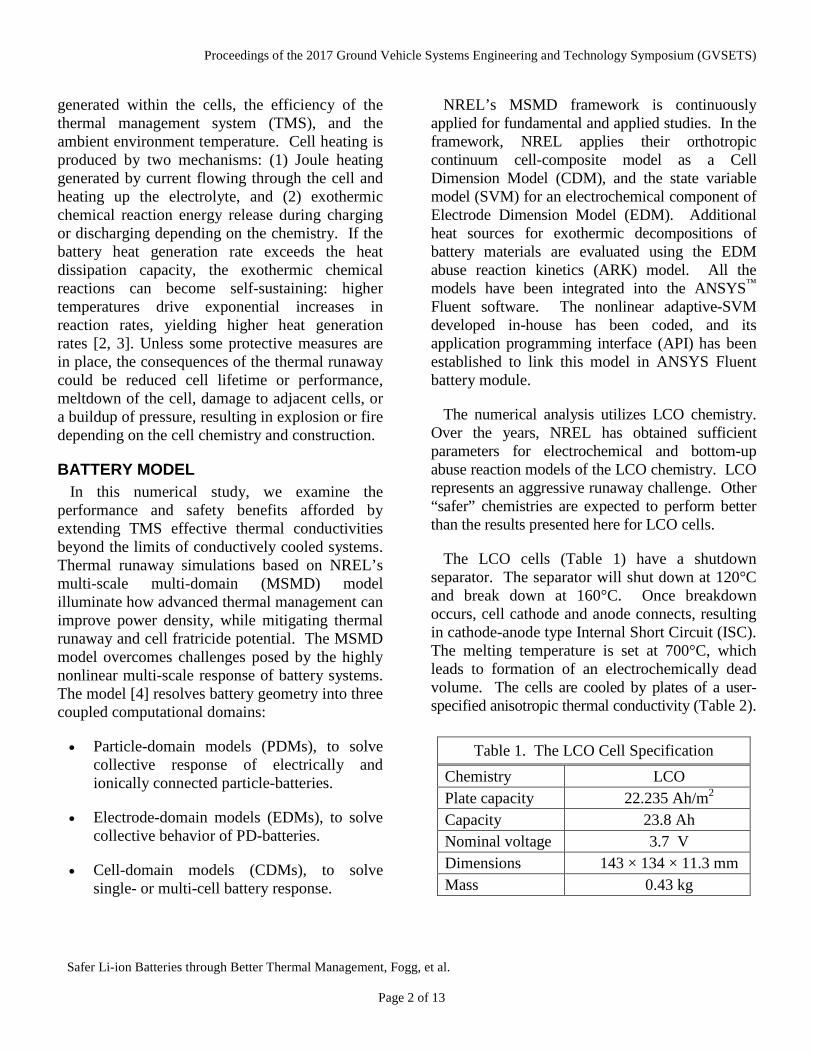
Table 1. The LCO Cell Specification Chemistry LCO Plate capacity 22.235 Ah/m2 Capacity 23.8 Ah Nominal voltage 3.7 V Dimensions 143 × 134 × 11.3 mm Mass 0.43 kg
Proceedings of the 2017 Ground Vehicle Systems Engineering and Technology Symposium (GVSETS)
Safer Li-ion Batteries through Better Thermal Management, Fogg, et al.
Page 3 of 13
The lowest thermal conductivity simulates aluminum conductive plates (k=200 W/m-K), but the values can be increased to simulate the effects of emerging high performance TMS, such as Creare’s phase change TMS with effective conductivities exceeding 1,200 W/m-K. The pack heat rejection surfaces are assumed to be constant at 23°C and located along the three non-terminal sides.
The Three Cell Module The battery module for this study is composed
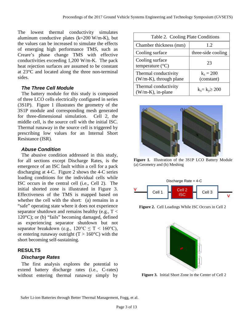
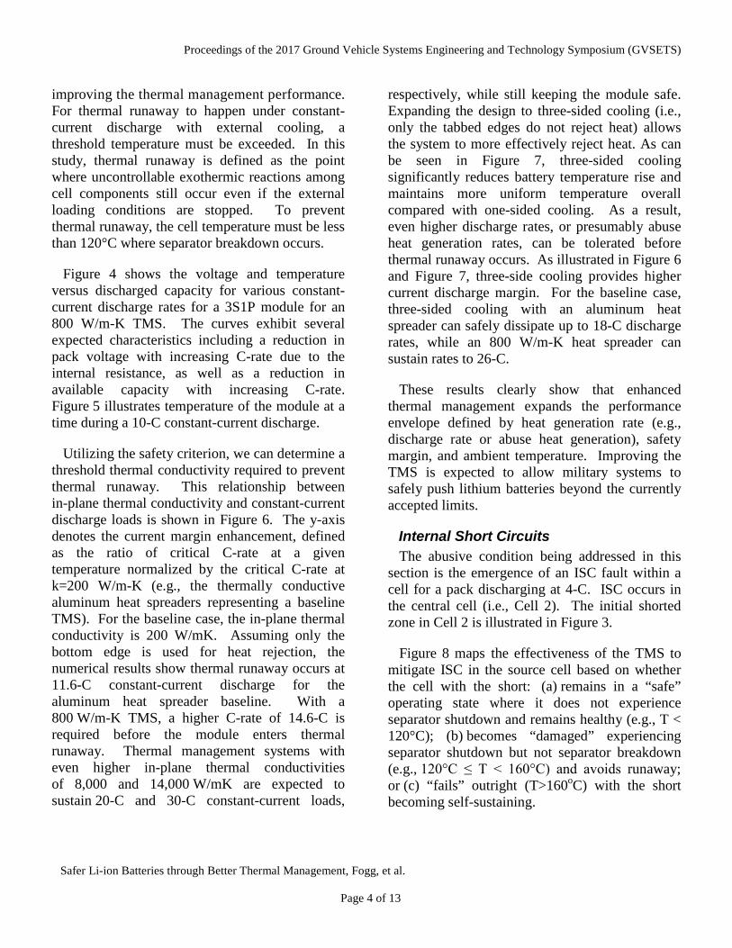
of three LCO cells electrically configured in series (3S1P). Figure 1 illustrates the geometry of the 3S1P module and corresponding mesh generated for three-dimensional simulation. Cell 2, the middle cell, is the source cell with the initial ISC. Thermal runaway in the source cell is triggered by prescribing low values for an Internal Short Resistance (ISR).
Abuse Condition The abusive condition addressed in this study,
for all sections except Discharge Rates, is the emergence of an ISC fault within a cell for a pack discharging at 4-C. Figure 2 shows the 4-C series loading conditions for the individual cells while ISC occurs in the central cell (i.e., Cell 2). The initial shorted zone is illustrated in Figure 3. Effectiveness of the TMS is mapped based on whether the cell with the short: (a) remains in a “safe” operating state where it does not experience separator shutdown and remains healthy (e.g., T < 120°C); or (b) “fails” becoming damaged, defined as experiencing separator shutdown but not separator breakdown (e.g., 120°C ≤ T < 160°C), or entering runaway outright (T > 160°C) with the short becoming self-sustaining.
RESULTS Discharge Rates The first analysis explores the potential to
extend battery discharge rates (i.e., C-rates) without entering thermal runaway simply by
Figure 1. Illustration of the 3S1P LCO Battery Module (a) Geometry and (b) Meshing
V V
Cell 1 Cell 2 ISC Cell 3
Discharge Rate = 4-C
Figure 2. Cell Loadings While ISC Occurs in Cell 2
Figure 3. Initial Short Zone in the Center of Cell 2
Table 2. Cooling Plate Conditions
Chamber thickness (mm) 1.2 Cooling surface three-side cooling Cooling surface temperature (°C) 23
Thermal conductivity (W/m-K), through plane
kz = 200 (constant)
Thermal conductivity (W/m-K), in-plane kx= ky≥ 200
Proceedings of the 2017 Ground Vehicle Systems Engineering and Technology Symposium (GVSETS)
Safer Li-ion Batteries through Better Thermal Management, Fogg, et al.
Page 4 of 13
improving the thermal management performance. For thermal runaway to happen under constant-current discharge with external cooling, a threshold temperature must be exceeded. In this study, thermal runaway is defined as the point where uncontrollable exothermic reactions among cell components still occur even if the external loading conditions are stopped. To prevent thermal runaway, the cell temperature must be less than 120°C where separator breakdown occurs.
Figure 4 shows the voltage and temperature versus discharged capacity for various constant-current discharge rates for a 3S1P module for an 800 W/m-K TMS. The curves exhibit several expected characteristics including a reduction in pack voltage with increasing C-rate due to the internal resistance, as well as a reduction in available capacity with increasing C-rate. Figure 5 illustrates temperature of the module at a time during a 10-C constant-current discharge.
Utilizing the safety criterion, we can determine a threshold thermal conductivity required to prevent thermal runaway. This relationship between in-plane thermal conductivity and constant-current discharge loads is shown in Figure 6. The y-axis denotes the current margin enhancement, defined as the ratio of critical C-rate at a given temperature normalized by the critical C-rate at k=200 W/m-K (e.g., the thermally conductive aluminum heat spreaders representing a baseline TMS). For the baseline case, the in-plane thermal conductivity is 200 W/mK. Assuming only the bottom edge is used for heat rejection, the numerical results show thermal runaway occurs at 11.6-C constant-current discharge for the aluminum heat spreader baseline. With a 800 W/m-K TMS, a higher C-rate of 14.6-C is required before the module enters thermal runaway. Thermal management systems with even higher in-plane thermal conductivities of 8,000 and 14,000 W/mK are expected to sustain 20-C and 30-C constant-current loads,
respectively, while still keeping the module safe. Expanding the design to three-sided cooling (i.e., only the tabbed edges do not reject heat) allows the system to more effectively reject heat. As can be seen in Figure 7, three-sided cooling significantly reduces battery temperature rise and maintains more uniform temperature overall compared with one-sided cooling. As a result, even higher discharge rates, or presumably abuse heat generation rates, can be tolerated before thermal runaway occurs. As illustrated in Figure 6 and Figure 7, three-side cooling provides higher current discharge margin. For the baseline case, three-sided cooling with an aluminum heat spreader can safely dissipate up to 18-C discharge rates, while an 800 W/m-K heat spreader can sustain rates to 26-C.
These results clearly show that enhanced thermal management expands the performance envelope defined by heat generation rate (e.g., discharge rate or abuse heat generation), safety margin, and ambient temperature. Improving the TMS is expected to allow military systems to safely push lithium batteries beyond the currently accepted limits.
Internal Short Circuits The abusive condition being addressed in this
section is the emergence of an ISC fault within a cell for a pack discharging at 4-C. ISC occurs in the central cell (i.e., Cell 2). The initial shorted zone in Cell 2 is illustrated in Figure 3.
Figure 8 maps the effectiveness of the TMS to mitigate ISC in the source cell based on whether the cell with the short: (a) remains in a “safe” operating state where it does not experience separator shutdown and remains healthy (e.g., T < 120°C); (b) becomes “damaged” experiencing separator shutdown but not separator breakdown (e.g., 120°C ≤ T < 160°C) and avoids runaway; or (c) “fails” outright (T>160oC) with the short becoming self-sustaining.

Proceedings of the 2017 Ground Vehicle Systems Engineering and Technology Symposium (GVSETS)
Safer Li-ion Batteries through Better Thermal Management, Fogg, et al.
Page 5 of 13
Figure 4. Voltage (Top) and Temperature (Bottom) Responses of 3S1P Module with 800 W/m-K TMS during Constant-Current Discharge
Figure 5. Temperature Distribution of 3S1P Module with 800 W/m-K TMS during 10-C Constant-Current
Figure 6. Higher Discharge Rates Tolerated with Better Thermal Management
Figure 7. Comparison of Temperature Distribution of the 3S1P Module with One-Sided and Three-Sided
Figure 8. Summary of ISC Mitigation

Proceedings of the 2017 Ground Vehicle Systems Engineering and Technology Symposium (GVSETS)
Safer Li-ion Batteries through Better Thermal Management, Fogg, et al.
Page 6 of 13
The area above the line indicates a stable condition where the abuse heat is removed with little temperature rise and the short circuit does not propagate, thereby preventing thermal runaway. In the area below the line, the TMS cannot remove the heat, allowing thermal runaway conditions to emerge. The critical ISC magnitude is about 60 mΩ, and effective axial thermal conductivity has a small impact on the critical ISC magnitude due to the low thermal conductivity of the cell material itself.
Cathode-anode type shorts play an important role in determining thermal runaway propagation within the fault cells and to the adjacent cells. The magnitude of the ISR affects the likelihood that the cell will enter thermal runaway. Larger resistance values limit the current flux, and the corresponding joule heating, through the shorted area. Small ISR values induced significant current flow, which quickly heats the affected region, enhancing the likelihood for runaway. As long as the TMS can remove heat at close to the rate it is being generated while remaining under the separator shutdown temperature, the cell and the pack remains healthy. Hence, improved thermal management extends the safe operating envelope by increasing the tolerance for low-grade ISC faults.
Cell Fratricide Effective thermal management can potentially
mitigate failure propagation to adjacent cells (e.g., cell fratricide). Using the same analysis methods and safety criteria as for the ISC protection study, we determined the impact thermal management has on whether neighboring cells become compromised following the emergence of an ISC fault within a cell (e.g., Cell 2) for a pack discharging at 4-C. Figure 2 shows the loading conditions for the individual cells while ISC occurs in the central cell (e.g., Cell 2). As before, the initial shorted zone in Cell 2 is illustrated in Figure 3.
Figure 9 maps the results for 33 simulations, where red, yellow, and green stand for cells adjacent to the one with the ISC event becoming failed, damaged, or safe, based on the separator health. For a given ISR value, increasing the effective thermal conductivity decreases the likelihood the cell becomes damaged or fails. However, this map has unique characteristics in that extremely aggressive shorts (e.g., <5 mΩ) appear to be self-limiting and do not cause fratricide.
Although low ISR values will damage the cell in which the short originates, these events, especially if highly localized, appear to be self-limiting with regards to fratricide of adjacent cells. These highly aggressive events generate significant heat on a volumetric basis that quickly elevates the temperature of the affected area beyond the 700°C
Runaway Propagation
Separator Damage
Unaffected
Figure 9. Cell Fratricide Potential for a Pack of 20 A-hr Cells as a Function of the Thermal Management System Effective Thermal Conductivity and the Initial Internal Short Resistance of the Originally Failing Cell. Aluminum heat spreaders (k=200W/m-K) are prone to multiple cells entering runaway from an internally shorted cell. Higher performing thermal management systems can limit runaway propagation and damage to a small subset of cells, yielding safer battery systems.

Proceedings of the 2017 Ground Vehicle Systems Engineering and Technology Symposium (GVSETS)
Safer Li-ion Batteries through Better Thermal Management, Fogg, et al.
Page 7 of 13
limit corresponding to electrochemically dead volumes. These failed regions stop producing heat. With little time to generate and diffuse heat to surrounding areas, the failure isolates itself and dies out.
Figure 10 shows peak temperature profiles of Cell 1 and Cell 2 with effective thermal conductivity of 200 W/m-K at ISR of 60 mΩ, 55 mΩ, and 2 mΩ, respectively. The solid lines represent the maximum temperature of Cell 2, and the dashed lines represent the maximum temperature of Cell 1. In Figure 10, for an ISR of 60 mΩ, the peak temperatures of Cell 1 and Cell 2 are less than 100°C and 200°C, respectively. According to the safety criteria, the cells adjacent to the shorted cell remain in a safe condition. It implies that the effective thermal conductivity of the TMS is able to reject the ISC-generated heat and safely control the temperature in each cell.
Reducing the magnitude of the ISR to 55 mΩ leads to more heat generation. The heat slowly
builds in Cell 2 until separator breakdown and runaway occurs, leading to massive abuse heat generation. The abuse heat propagates to the adjacent cells, ultimately causing the peak temperature of the adjacent cells (e.g., Cell 1) to exceed 160°C, which indicates runaway in the adjacent cells and failure propagation.
Reducing the ISR value to a very aggressive value of 2 mΩ illustrates the self-limiting behavior with regards to fratricide. Clearly, the lower the short resistance is, the greater the associated volumetric joule heating will be. Hence, the Cell 2 peak temperature climbs almost instantaneously for this case, quickly exceeding the electrochemically dead volume thresholds. However, as illustrated by Figure 10, the Cell 2 peak temperature drops dramatically with time. The total heat generated is small, and the diffused heat from the initially shorted region is unable to sustain and self-propagate the exothermic runaway reactions. Some of the heat generated during the initial short event diffuses to Cell 1, but the
Figure 10. Peak Temperature Profiles of Cell 1 and Cell 2 for the TMS with Effective Thermal Conductivity of 200 W/m-K.

Proceedings of the 2017 Ground Vehicle Systems Engineering and Technology Symposium (GVSETS)
Safer Li-ion Batteries through Better Thermal Management, Fogg, et al.
Page 8 of 13
available thermal energy is limited and the peak Cell 1 temperature stabilizes after approximately 4 seconds.
Another way to see this phenomenon is through the abuse heat generation rates. Figure 11 shows abuse heat generation profiles after 20 seconds for an ISR of 2 mΩ, 55 mΩ, and 60 mΩ, respectively. It shows that there is no significant abuse heat at the case of ISR of 2 mΩ or 60 mΩ, while the heat generation front for the 55 mΩ case continues to expand. The difference between the three cases is that: (a) large ISR values do not generate sufficient heat to trigger self-sustaining thermal runaway reactions and thermal management can prevent failures altogether; (b) small ISR values self-heat but destroy themselves before they have time to expand and self-propagate; and (c) moderate ISR values generate heat faster than the TMS can dissipate, leading to expanding abuse generation fronts which propagate throughout a battery pack.
Figure 12 shows the change of overall internal short resistance of Cell 1 and 2 for various initial short resistances. When ISR is 60 mΩ or greater, the resistance of Cells 1 and 2 do not change appreciably. The resistance of Cell 2 is higher than 4.5×10²³ mΩ, which indicates no short in Cell 2. Thus, the cathode-anode short circuit of Cell 2 does not expand.
Initially Shorted Cell Adjacent Cell
Figure 12. Growth of Internal Short Circuit in Cell 2 (Left) and Cell 1 (Right) Due to Separator Breakdown Leading Cathode-Anode Short Circuit
ISR = 2 mΩ ISR = 55 mΩ ISR = 60 mΩ
Figure 11. Abuse Heat Generation Profiles of 3S1P Module for k = 200 W/m-K after 20 Seconds
Proceedings of the 2017 Ground Vehicle Systems Engineering and Technology Symposium (GVSETS)
Safer Li-ion Batteries through Better Thermal Management, Fogg, et al.
Page 9 of 13
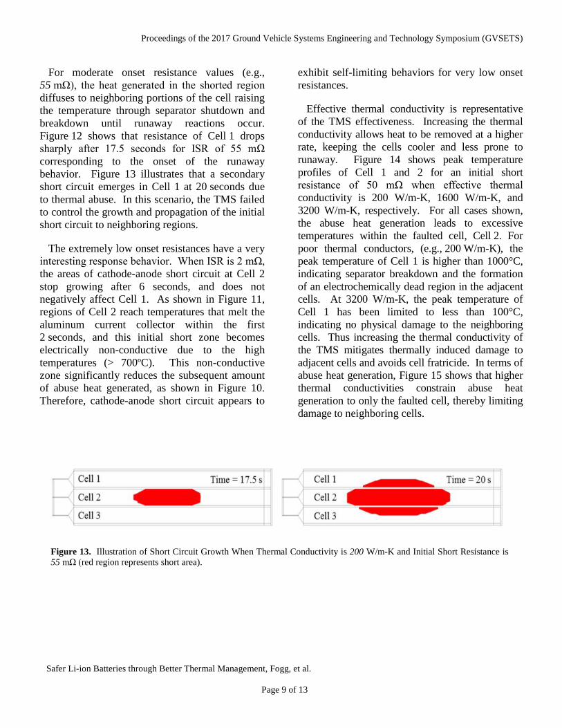
For moderate onset resistance values (e.g., 55 mΩ), the heat generated in the shorted region diffuses to neighboring portions of the cell raising the temperature through separator shutdown and breakdown until runaway reactions occur. Figure 12 shows that resistance of Cell 1 drops sharply after 17.5 seconds for ISR of 55 mΩ corresponding to the onset of the runaway behavior. Figure 13 illustrates that a secondary short circuit emerges in Cell 1 at 20 seconds due to thermal abuse. In this scenario, the TMS failed to control the growth and propagation of the initial short circuit to neighboring regions.
The extremely low onset resistances have a very interesting response behavior. When ISR is 2 mΩ, the areas of cathode-anode short circuit at Cell 2 stop growing after 6 seconds, and does not negatively affect Cell 1. As shown in Figure 11, regions of Cell 2 reach temperatures that melt the aluminum current collector within the first 2 seconds, and this initial short zone becomes electrically non-conductive due to the high temperatures (> 700ºC). This non-conductive zone significantly reduces the subsequent amount of abuse heat generated, as shown in Figure 10. Therefore, cathode-anode short circuit appears to
exhibit self-limiting behaviors for very low onset resistances.
Effective thermal conductivity is representative of the TMS effectiveness. Increasing the thermal conductivity allows heat to be removed at a higher rate, keeping the cells cooler and less prone to runaway. Figure 14 shows peak temperature profiles of Cell 1 and 2 for an initial short resistance of 50 mΩ when effective thermal conductivity is 200 W/m-K, 1600 W/m-K, and 3200 W/m-K, respectively. For all cases shown, the abuse heat generation leads to excessive temperatures within the faulted cell, Cell 2. For poor thermal conductors, (e.g., 200 W/m-K), the peak temperature of Cell 1 is higher than 1000°C, indicating separator breakdown and the formation of an electrochemically dead region in the adjacent cells. At 3200 W/m-K, the peak temperature of Cell 1 has been limited to less than 100°C, indicating no physical damage to the neighboring cells. Thus increasing the thermal conductivity of the TMS mitigates thermally induced damage to adjacent cells and avoids cell fratricide. In terms of abuse heat generation, Figure 15 shows that higher thermal conductivities constrain abuse heat generation to only the faulted cell, thereby limiting damage to neighboring cells.
Figure 13. Illustration of Short Circuit Growth When Thermal Conductivity is 200 W/m-K and Initial Short Resistance is 55 mΩ (red region represents short area).

Proceedings of the 2017 Ground Vehicle Systems Engineering and Technology Symposium (GVSETS)
Safer Li-ion Batteries through Better Thermal Management, Fogg, et al.
Page 10 of 13
Insulation Layers In this final study, different thermal conductivity
insulating layers (2 ≤ k ≤ 200 W/m-K) are placed on one side of the central pouch cells with an aluminum heat spreader (k = 200 W/m-K) on the other side to determine if strategic placement of insulating layers can mitigate fratricide. The fratricide results, summarized in Table 3, indicate that insulating layers do not offer significant cell fratricide protection. High-conductance TMSs provide equal or better fratricide protection because heat is removed from the system. Insulating layers, on the other hand, delay the propagation of heat within the pack but do not prevent heat propagation, which ultimately results in fratricide in the absence of an effective TMS.
k = 202.4 W/m-K k = 1600 W/m-K k = 3200 W/m-K
Figure 14. Peak Temperature Profiles of Cell 1 and Cell 2 with Initial Short Resistance of 50 mΩ
Figure 15. Abuse Heat Generation Profiles of 3S1P Module with Initial Short Resistance of 50 mΩ After 15 Seconds
Table 3. Insulating Layer Fratricide Results
ISR (mΩ)
Thermal Conductivity, kz ,(W/m-K)
2 10 200 2 - Pass Fratricide 5 Fratricide Fratricide Fratricide 10 - Fratricide Fratricide 20 - Fratricide Fratricide 30 - Fratricide - 40 - Fratricide - 50 - Fratricide Fratricide 55 Fratricide Fratricide Fratricide 60 - Pass Pass
Proceedings of the 2017 Ground Vehicle Systems Engineering and Technology Symposium (GVSETS)
Safer Li-ion Batteries through Better Thermal Management, Fogg, et al.
Page 11 of 13
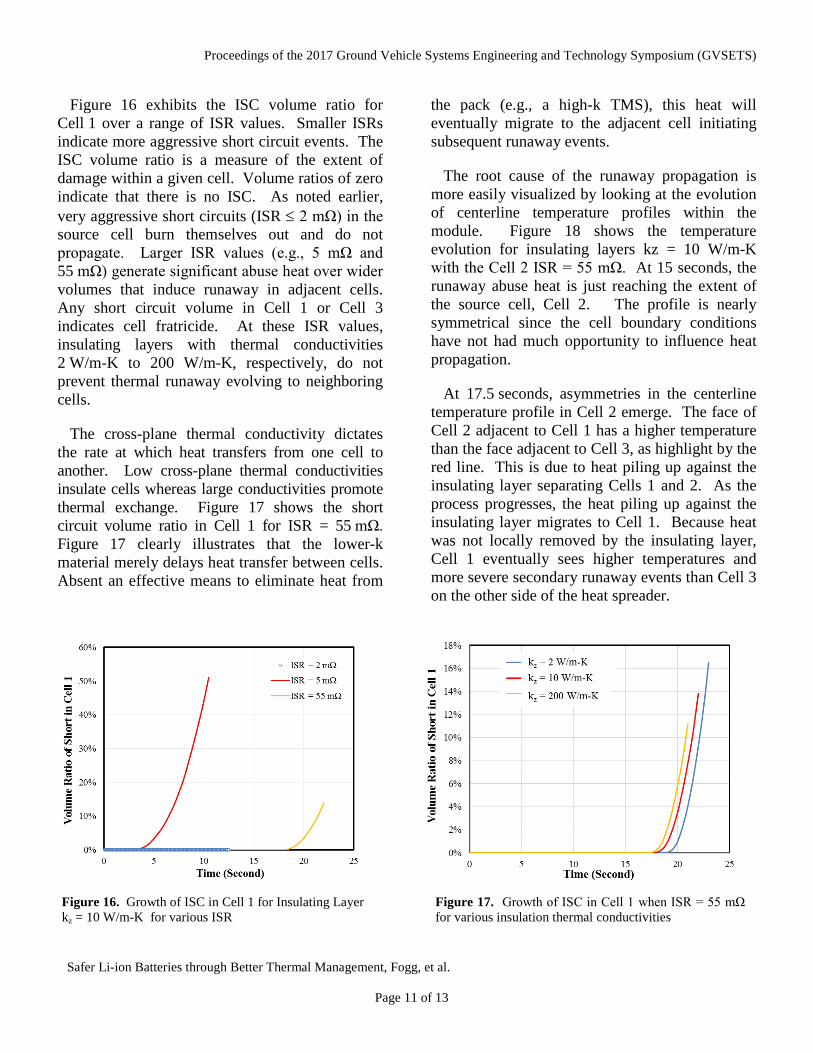
Figure 16 exhibits the ISC volume ratio for Cell 1 over a range of ISR values. Smaller ISRs indicate more aggressive short circuit events. The ISC volume ratio is a measure of the extent of damage within a given cell. Volume ratios of zero indicate that there is no ISC. As noted earlier, very aggressive short circuits (ISR ≤ 2 mΩ) in the source cell burn themselves out and do not propagate. Larger ISR values (e.g., 5 mΩ and 55 mΩ) generate significant abuse heat over wider volumes that induce runaway in adjacent cells. Any short circuit volume in Cell 1 or Cell 3 indicates cell fratricide. At these ISR values, insulating layers with thermal conductivities 2 W/m-K to 200 W/m-K, respectively, do not prevent thermal runaway evolving to neighboring cells.
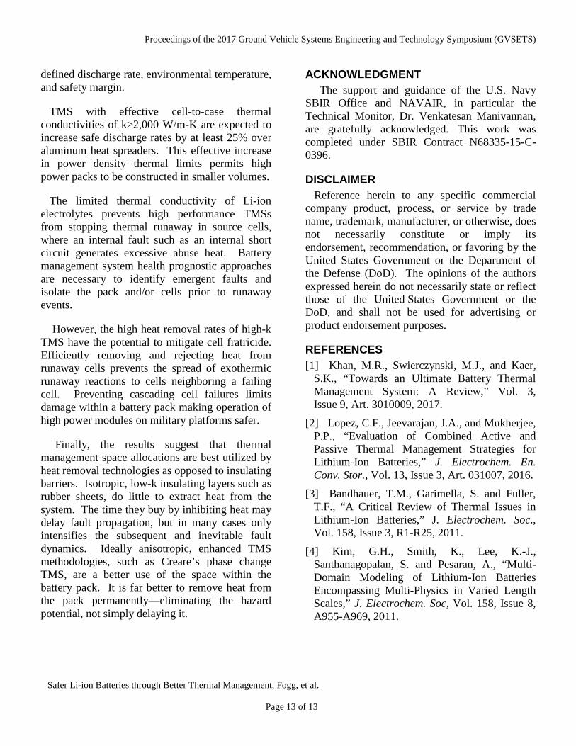
The cross-plane thermal conductivity dictates the rate at which heat transfers from one cell to another. Low cross-plane thermal conductivities insulate cells whereas large conductivities promote thermal exchange. Figure 17 shows the short circuit volume ratio in Cell 1 for ISR = 55 mΩ. Figure 17 clearly illustrates that the lower-k material merely delays heat transfer between cells. Absent an effective means to eliminate heat from
the pack (e.g., a high-k TMS), this heat will eventually migrate to the adjacent cell initiating subsequent runaway events.
The root cause of the runaway propagation is more easily visualized by looking at the evolution of centerline temperature profiles within the module. Figure 18 shows the temperature evolution for insulating layers kz = 10 W/m-K with the Cell 2 ISR = 55 mΩ. At 15 seconds, the runaway abuse heat is just reaching the extent of the source cell, Cell 2. The profile is nearly symmetrical since the cell boundary conditions have not had much opportunity to influence heat propagation.
At 17.5 seconds, asymmetries in the centerline temperature profile in Cell 2 emerge. The face of Cell 2 adjacent to Cell 1 has a higher temperature than the face adjacent to Cell 3, as highlight by the red line. This is due to heat piling up against the insulating layer separating Cells 1 and 2. As the process progresses, the heat piling up against the insulating layer migrates to Cell 1. Because heat was not locally removed by the insulating layer, Cell 1 eventually sees higher temperatures and more severe secondary runaway events than Cell 3 on the other side of the heat spreader.
Figure 16. Growth of ISC in Cell 1 for Insulating Layer kz = 10 W/m-K for various ISR
Figure 17. Growth of ISC in Cell 1 when ISR = 55 mΩ for various insulation thermal conductivities

Proceedings of the 2017 Ground Vehicle Systems Engineering and Technology Symposium (GVSETS)
Safer Li-ion Batteries through Better Thermal Management, Fogg, et al.
Page 12 of 13
Although heat spreader propagates the heat more quickly, it also removes heat and mitigates the extent of the damage. These simulations show allocating space to heat removal as opposed to insulation creates safer battery packs. High-k TMS remove heat from the system, preventing it from reaching the adjacent cells. If the thermal runaway event in the source cell generates heat at a rate beyond the removal capacity of the TMS, cell fratricide will eventually occur.
However, effective in-plane conductivities around 2,000 W/m-K have the potential to eliminate fratricide for all but the most extreme runaway scenarios.
CONCLUSION Simulations of the complex thermo-
electrochemical dynamics of Li-ion batteries indicate that the high-performance TMSs can expand the three-parameter operating space
Cell 3
Cell 2
Cell 1
Cell 3
Cell 2
Cell 1
Cell 3
Cell 2
Cell 1
Cell 3
Cell 2
Cell 1
(a) (b)
(c) (d)
t = 15 second t = 17.5 second
t = 20 second t = 22.5 second
Figure 18. Centerline Temperature Profiles of 3S1P Battery Module for kz = 10 W/m-K and ISR = 55 mΩ at: (a) 15 seconds, (b) 17.5 seconds, (c) 20 seconds, and (d) 22.5 seconds
Proceedings of the 2017 Ground Vehicle Systems Engineering and Technology Symposium (GVSETS)
Safer Li-ion Batteries through Better Thermal Management, Fogg, et al.
Page 13 of 13
defined discharge rate, environmental temperature, and safety margin.
TMS with effective cell-to-case thermal conductivities of k>2,000 W/m-K are expected to increase safe discharge rates by at least 25% over aluminum heat spreaders. This effective increase in power density thermal limits permits high power packs to be constructed in smaller volumes.
The limited thermal conductivity of Li-ion electrolytes prevents high performance TMSs from stopping thermal runaway in source cells, where an internal fault such as an internal short circuit generates excessive abuse heat. Battery management system health prognostic approaches are necessary to identify emergent faults and isolate the pack and/or cells prior to runaway events.
However, the high heat removal rates of high-k TMS have the potential to mitigate cell fratricide. Efficiently removing and rejecting heat from runaway cells prevents the spread of exothermic runaway reactions to cells neighboring a failing cell. Preventing cascading cell failures limits damage within a battery pack making operation of high power modules on military platforms safer.
Finally, the results suggest that thermal management space allocations are best utilized by heat removal technologies as opposed to insulating barriers. Isotropic, low-k insulating layers such as rubber sheets, do little to extract heat from the system. The time they buy by inhibiting heat may delay fault propagation, but in many cases only intensifies the subsequent and inevitable fault dynamics. Ideally anisotropic, enhanced TMS methodologies, such as Creare’s phase change TMS, are a better use of the space within the battery pack. It is far better to remove heat from the pack permanently—eliminating the hazard potential, not simply delaying it.
ACKNOWLEDGMENT The support and guidance of the U.S. Navy
SBIR Office and NAVAIR, in particular the Technical Monitor, Dr. Venkatesan Manivannan, are gratefully acknowledged. This work was completed under SBIR Contract N68335-15-C-0396.
DISCLAIMER Reference herein to any specific commercial
company product, process, or service by trade name, trademark, manufacturer, or otherwise, does not necessarily constitute or imply its endorsement, recommendation, or favoring by the United States Government or the Department of the Defense (DoD). The opinions of the authors expressed herein do not necessarily state or reflect those of the United States Government or the DoD, and shall not be used for advertising or product endorsement purposes.
REFERENCES [1] Khan, M.R., Swierczynski, M.J., and Kaer,
S.K., “Towards an Ultimate Battery Thermal Management System: A Review,” Vol. 3, Issue 9, Art. 3010009, 2017.
[2] Lopez, C.F., Jeevarajan, J.A., and Mukherjee, P.P., “Evaluation of Combined Active and Passive Thermal Management Strategies for Lithium-Ion Batteries,” J. Electrochem. En. Conv. Stor., Vol. 13, Issue 3, Art. 031007, 2016.
[3] Bandhauer, T.M., Garimella, S. and Fuller, T.F., “A Critical Review of Thermal Issues in Lithium-Ion Batteries,” J. Electrochem. Soc., Vol. 158, Issue 3, R1-R25, 2011.
[4] Kim, G.H., Smith, K., Lee, K.-J., Santhanagopalan, S. and Pesaran, A., “Multi-Domain Modeling of Lithium-Ion Batteries Encompassing Multi-Physics in Varied Length Scales,” J. Electrochem. Soc, Vol. 158, Issue 8, A955-A969, 2011.