S6.2 Controller - Armour Homeecom.armourhome.co.uk/files/systemline/Systemline_S6.2/... ·...
24
S6.2 Controller S6.2 Controller Installation Guide
Transcript of S6.2 Controller - Armour Homeecom.armourhome.co.uk/files/systemline/Systemline_S6.2/... ·...

S6.2 Controller S6.2 Controller Installation Guide

PAGE 2
Declaration Of Conformity
The Systemline S6.2 Multi-room Controller has been designed and independently tested to be in compliance with the following standards:
SAFETY BS EN 60065:2002 IEC 60065:2001 7th Edition
EMC BS EN 55022 Class B 2006 BS EN 55103-1:1997 BS EN 55103-2:1996 BS EN 61000-4-(2 to 6 & 11) 2004
This product is designed and manufactured to comply with the radio interference requirements of EEC directive 89/336/EEC, 93/68/EEC and 73/23/EEC.
Safety
This Symbol is to alert the user to the presence of dangerous voltages inside the Systemline Power supplies. To reduce the risk of electric shock do not dismantle these power supplies.
This symbol is to alert the user of important operating instructions included in this manual accompanying the Systemline Unit.
1. Read these instructions.
2. Keep these instructions.
3. Heed all warnings.
4. Follow all instructions.
5. Do not use this apparatus near water.
6. Clean only with dry cloth.
7. Do not block any ventilation openings. Install only in accordance with the manufacturer’s instructions.
8. Do not install near any heat sources such as radiators, heat registers, stoves, or other apparatus (including amplifiers) that produce heat.
9. Protect the power cord from being walked on or pinched, particularly at plugs, convenience receptacles and the point at which they exit from the apparatus.
10. Only use attachments/accessories specified by the manufacturer.
11. Use only with the cart, stand, tripod, bracket or table specified by the manufacturer, or sold with the apparatus. When a cart is used, use caution when moving the cart/apparatus to avoid injury from tip-over.
12. Unplug this apparatus during lightning storms or when unused for long periods of time.
13. Refer all servicing to qualified personnel. Servicing is required when the apparatus has been damaged in any way, such as power supply cord or plug is damaged, liquid has been spilled or objects have fallen in to the apparatus, the apparatus has been exposed to rain or moisture, does not operate normally or has been dropped.
WARNING: Do Not Remove the cover. There are no user serviceable parts inside. Refer all servicing issues to qualified personnel.
WARNING: To reduce the risk of fire or electric shock, do not expose this product to rain or moisture.
This apparatus must not be exposed to dripping or splashing. Objects filled with liquids such as vases must not be placed on the apparatus. The rear panel power switch disconnects mains live only. The power cord must be disconnected from the rear of the apparatus, or the wall socket, to provide total isolation. One or other of these connections must be readily accessible when the apparatus is in use.
WARNING: Changes or modifications not expressly approved by the party responsible for Compliance could void the user’s authority to operate the equipment.
Notes on Handling
• When shipping the Systemline S6.2 Controller product, always use the original shipping carton and packing materials. For maximum protection, repack the unit as it was originally packed at the factory.
• Do not use volatile liquids, such as insect spray, near the product. Do not leave rubber or plastic products in contact with the product for a long time. They will leave marks on the finish.
• The top and rear panels of the product may become warm after a long period of use. This is normal and not a malfunction.
• When the product is not in use, be sure to turn off the power.
Notes on Locating
• Locate this product away from any direct sources of heat (e.g. radiators or heaters) or magnetism (old style TVs or computer monitors).
• Avoid placing the unit in the direct airflow from an air conditioning unit as this may lead to condensation being developed inside the product.
• The rocker switch at the rear of the equipment is the primary means of disconnecting the mains supply and therefore this should be accessible. If access is not feasible then a secondary means of disconnection must be readily available and accessible.

PAGE 3
Notes on Cleaning
• Use a dry soft cloth for cleaning.
• For stubborn dirt, soak the cloth in a weak detergent solution, wring very well and wipe the exterior surfaces of the product. Use a dry cloth to wipe it dry. Do not use any type of solvent, such as thinners and benzene, as they may damage the surface of the product.
• If you use a chemical saturated cloth to clean the unit, follow that product’s instructions.
Notes on Moisture Condensation
Moisture condensation is likely to damage this product. Please read the following carefully:
• Moisture inside the product is most likely to arise when transferring the unit from a cold location to a warm one. Wherever possible avoid doing this, or let the unit acclimatise for at least 3 hours before attempting to switch it on.
• Do not use the product in a cold room where you just turned on the heater, or a place where the cold wind from the air conditioner directly hits the unit.
Record Your Serial Number
The serial number are located on the back of your product. For your future convenience, we suggest that you record this number here:
Serial No..…………………............................………
AcknowledgementsCopyright © 2010 Armour Home Electronics Ltd. All rights reserved.
The information in this guide is believed to be correct as of the date of publication. However, our policy is one of continuous development and so the information is subject to change without notice, and does not represent a commitment on the part of Armour Home Electronics Ltd.
Systemline is a registered trademark of Armour Home Electronics Ltd. Sistema 45 and System 45 are trademarks of AVE s.p.A. All other product names are trademarks or registered trademarks of their respective owners.
Armour Home Electronics Ltd Stortford Hall Industrial Park Dunmow Road Bishops Stortford Hertfordshire CM23 5GZ
Web: www.systemline.co.uk
Terminology
This guide uses the following terminology to refer to the components of the Systemline S6.2 Multi-room system:
Zone – an audio system in a listening room or location, typically consisting of a pair of Systemline ceiling-mounted speakers or other bookshelf or floor-standing speakers and an optional keypad, able to play music either from the remote system or a local source.
Remote system – the hi-fi system providing audio distributed to each zone.
Multi-room system – an audio or audio visual system that can be used in any room in the home. Sometimes colloquially referred to as a built-in sound system or distributed audio system.
Multi-source multi-zone – a system where different audio sources can be played in different rooms simultaneously
System room – the location of the hi-fi system providing the audio sources to be distributed via Systemline S6.2 Controller.
Local input – each zone can accept a local stereo audio input. This input can be listened to in that zone, hence the term local, although the actual location of the audio source need not be local, it could be in another room or other discreet location.
About This Guide
This Installation Guide is intended for audio installation engineers, or trained qualified electricians, involved in the actual installation and interconnection of a Systemline S6.2 Controller system. It consists of the following chapters:
• Connecting the Systemline S6.2 Controller has diagrams showing how the components should be connected and wired
• Configuring the Systemline S6.2 Controller using a PC gives information about setting up a Systemline S6.2 Controller installation via the PC programming software.
• Touchscreen Settings goes into detail about the various different user options available to change on the touchscreen.

Tab
le o
f Con
tent
s
PAGE 4
1 Introduction 5
2 Connecting the S6.2 Controller in a System 7
2.1 System Requirements 72.2 Mains Voltage Selection and Fuses 82.3 Wiring Layout 82.4 Installation Records 82.5 Wiring the Components 82.6 Front Panel Controls 102.7 Front Panel Status Display 102.8 Rear Panel Connections 112.9 Switching on the S6.2 Controller 112.10 Installation of Sources, Lighting Controls and
Other Units 11
3 Configuring the S6.2 Controller and Touchscreen Keypads Using a PC 12
3.1 Installation 12Installing the software on the host computer using the supplied CD-ROM 12
3.2 Discovering S6.2 units & changing IP address 133.3 Setting Touch Screen Keypad & wireless junction box addresses 143.4 Uploading firmware to touch screens, junction boxes & S6.2 Hub 143.5 Selecting S6.2 143.6 Adding Configurable Sources 153.7 Hub Audio Input Sources 153.8 Keypad Configuration Profile 163.9 Uploading keypad & wireless junction box
configurations 163.10 Configuring Audio Zone Settings 173.11 Saving Configurations 183.12 Loading Previously Saved .snc Files 18
4 Touch Screen Keypad Settings 19
4.1 Contrast 194.2 Modular Address 194.3 Touch Screen Calibration 194.4 Getting Out of Trouble 20

PAGE 5
Intr
oduc
tion
Audio Source Routing
Audio sources can be connected to each of the S6.2’s six audio inputs and then be controlled by the in wall or wireless touch screens. Sources can be controlled by
1 IntroductionThe Systemline S6.2 Controller is an eight zone six source multiroom audio system that incorporates RS232 control of external devices when used with touch screens. S6.2 is expandable to sixteen zones by using two units in one system.
infra-red (IR) or RS232 if used with a supported RS232 device such as the Systemline Audio Server.
Each zone also has a local audio source input, where the source is located in the zone itself but connects to the zone local input socket on the S6.2 Contoller. Local sources can be controlled by IR by using a stick on window emmitter from the local input wall plate.
Touch screens can also control other RS232 devices such as lighting and heating control systems. These must be a supported device,
the list of which appears on the configuration software.
A dedicated RS232 port on the rear of the unit can control a video matrix switch such as a Kramer unit or Armour HDMI 4x8 matrix.
This will then give audio and video switching to each zone.
The line level outputs of each zone require a suitable stereo power amplifier to drive a pair of speakers: a multi-channel amplifier is most often used for this such as the Sonance 1230.
Wireless
Touchscreen
To 7 O ther ZonesT V
Wireless Router
Speaker LevelOutput
HDMI Matr ix Switcher
VBLN plugs into RJ45 wal l p late us ing a standard patch cable
R ight Speaker
Lef t Speaker
Power Ampl i�er
S6.2 Control ler
Systemline Audio Ser ver
TouchScreenKeypad
Wireless Junc t ion Box
Stereo Audio RC A
Cat5 Cable
Ethernet
HDMI
Speaker Cable
IR
RS232
Key
Figure1.

PAGE 6
Intr
oduc
tion
All software for the S6.2 is updated via the Ethernet connection using a suitable Ethernet switch or router.
Two units can work on one system to give a sixteen zone system sharing RS232 devices but accessing 6 audio sources connected to each unit.

PAGE 7
Sec
tion
2 •
Con
nect
ing
the
Sys
tem2.1 System Requirements
1. The S6.2 Controller.
2. A stereo power amplifier for each pair of speakers connected to a zone. This should be located close to the S6.2 Controller.
3. Each Zone will require a control keypad from the following range.
• KPM7
• LKPM7
• Monochrome touch screen keypad
• Colour touch screen keypad
• Wireless touch screen keypad
It is possible to combine wireless touch screen control with one of any other wall mounted control keypad.
4. Speakers in each Zone.
5. Audio sources located by the S6.2 Controller such as:
• Systemline Audio Server
• Blu-ray Player
• Arcam DAB radio tuner
6. Ethernet connection to the house network using the RJ45 Ethernet socket.
7. Optional local audio system connected to a CIM/WE or CIM/PI2, most commonly the TV audio.
8. Optional Lighting control system connected to one of the available RS232 ports such as Lutron Grafik-eye or Lutron Homeworks.
9. Optional iPod dock system such as the Sonance iPort which is connected to one of the available RS232 ports.
10. Optional video distribution system connected to the Video RS232 control port such as the Armour 4x8 HDMI matrix or the Kramer VP-88ETH component matrix switch
11. Cables as required.
The following accessories are included with the S6.2 Controller:
•1 Systemline LRN7 Learning Remote Control
•8 SAIC Audio interconnects
•4 SL-WE IR window emitters
•2 SL-TE twin IR window emitters
•1 Mains cable, UK ad Euro types
•1 630mA fuse (for 230/240V)
•3 RS232 Null Modem cables
•3 RS232 Straight through cables
•1 Ethernet Patch Cable
•1 Software CD-ROM
•1 User Guide
•1 Installation Guide
Not Included with the S6.2 Controller are the following accessories that may be necessary in certain Installations:-
• USA/Canadian power cable
• RS232 cables if more than one type is required
• SL-WE or ST-TE window emitters if more IR source control is required
• CAT5e cables and connectors
During installation you will also require a PC or laptop PC running Microsoft Windows 2000 or higher.
All of the provided software should be taken to site, but you should check for updates before each installation at http://www.armourhe.co.uk/downloads/-software/systemnet_files
Note: Always read and comply with the manufacturer’s instructions supplied with any piece of equipment that is part of an S6.2 Controller installation.
2 Connecting the S6.2 Controller in a SystemA distributed audio system based around an S6.2 Controller will require a selection from the following items:
PAGE 8
Sec
tion
2 •
Con
nect
ing
the
Sys
tem
2.2 Mains Voltage Selection and Fuses
The S6.2 is shipped with the Voltage selector on the rear panel set to 240V and a 630mA fuse.
If the local mains supply is 110/120V ac,
• Change the Voltage selector switch setting to 120V
• Fit a 1.25mA fuse
• Obtain and fit a suitable 2 pin or 3 pin IEC mains cable/power cord
2.3 Wiring Layout
See Figure 2. Routing AV sources has not been shown for clarity.
2.4 Installation Records
When the installation has been designed and completed, record the details of the installation in the boxes provided on the back page of the User Guide for the information of the Users.
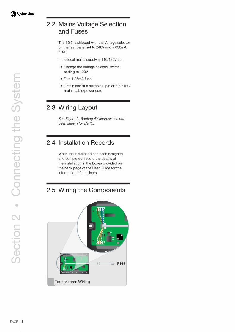
2.5 Wiring the Components
Touchscreen Wiring
RJ45

PAGE 9
Sec
tion
2 •
Con
nect
ing
the
Sys
tem
S6.2
Co
ntr
olle
r 2
WIN
DO
W E
MIT
TER
1W
IND
OW
EM
ITTE
R 2
WIN
DO
W E
MIT
TER
3W
IND
OW
EM
ITTE
R 4
WIN
DO
W E
MIT
TER
5W
IND
OW
EM
ITTE
R 6
SOU
RC
E 1
LOO
P O
UT
SOU
RC
E 2
LOO
P O
UT
SOU
RC
E 3
LOO
P O
UT
SOU
RC
E 4
LOO
P O
UT
SOU
RC
E 6
LOO
P O
UT
SOU
RC
E 5
LOO
P O
UT
LINK
ETHERNET
Mul
ti-ro
om C
ontr
olle
r
Lutr
on
™ G
rafik
Eye
Lig
hti
ng
Co
ntr
ol
Net
wo
rk S
wit
ch
Pow
er A
mp
lfier
ZO
NE
9
Co
lou
r To
uch
scre
en K
eyp
ad
Cei
ling
Mo
un
ted
Lo
ud
spea
kers
LE
FT
RIG
HT
CIM/PI
DV
D P
laye
r in
Lo
cal Z
on
e
Wireless Junction Box
Pow
er A
mp
lfier
ZO
NE
1
Bo
oks
hel
f or F
loo
rsta
nd
ing
Lo
ud
spea
kers
Co
lou
r To
uch
scre
en K
eyp
ad
Dis
pla
y
HD
MI R
ecei
ver
Sky
HD
Arc
am T
32
Syst
emlin
e A
ud
io S
erve
r
40VA
100-
240V
50/6
0Hz
VGA
KEYB
OA
RD
ETH
ERN
ET
S-VI
DEO
COM
POSI
TEVI
DEO
RS23
2
AUDIO OUTPUTS
AUDIO INPUTS
CO-A
XA
NA
LOG
DIG
ITA
L
AN
ALO
G
DIG
ITA
LIR
INPU
T
AN
ALO
G
DIG
ITA
LO
PTIC
AL
OU
TPU
T 1
OU
TPU
T 2
OU
TPU
T 3
Sto
rtfo
rd H
all I
nd
ust
rial
Par
k,
Bis
ho
ps
Sto
rtfo
rd, H
erts
, C
M23
5G
Z U
Kw
ww
.arm
ou
rhe.
co.u
k
DIG
ITA
L 1
AN
ALO
G2
AN
ALO
G3
USB
1U
SB2
POW
ER
OFF
ON
L R
L R
L R
L R
L R
321
Blu
ray
Play
er
Arm
ou
r 4×
8 H
DM
I Mat
rix
Wireless Junction Box
7 o
ther
zo
nes
7 o
ther
zo
nes
Ste
reo
Au
dio
RC
A
Ca
t5 C
ab
le
Eth
ern
et
HD
MI
Sp
ea
ke
r C
ab
le
IRRS
23
2
Ke
y
Wir
eles
s C
om
man
der
Wir
eles
s C
om
man
der
Oth
er R
S232
dev
ices
an
d a
ud
io s
ou
rces
Figure 2. Wiring Layout

PAGE 10
Sec
tion
2 •
Con
nect
ing
the
Sys
tem
2.6 Front Panel Controls
1. Front Panel Status Display – displays the status of the zones (see Section 2.7 for details).
2. Standby/Reset Button – use is not necessary during normal operation (unless instructed to do so by Armour Home Electronics Technical Support).
2
1
3
5
2
4
1
2.7 Front Panel Status Display
1. Zone Condition LEDs – shows the current state of each zone.
RED – Standby BLUE – System Input RED – Local Input
2. IR STATUS – IR window emitter activity.
3. COMMS – S6.2 command sent or received from a keypad.
4. BUS DATA – data to and from a touchscreen keypad.
5. RS232 – RS232 control and metadata between S6.2 Controller and source.
Note: LEDs 2–5 flash when signal activity occurs
or internal commands are processed.

PAGE 11
Sec
tion
2 •
Con
nect
ing
the
Sys
tem
WINDOW EMITTER 1 WINDOW EMITTER 2 WINDOW EMITTER 3 WINDOW EMITTER 4 WINDOW EMITTER 5 WINDOW EMITTER 6
SOURCE 1 LOOP OUT
SOURCE 2 LOOP OUT
SOURCE 3 LOOP OUT
SOURCE 4 LOOP OUT
SOURCE 6 LOOP OUT
SOURCE 5 LOOP OUT
LIN
K
ETH
ERN
ET
Multi-room Controller
6
1
2
7 8
3 4 10
11
12
14
13
5
9
2.8 Rear Panel Connections
1. Mains Power – ON\OFF switch.
2. IEC Mains Inlet
3. Direct/Remote Switch – when set to ‘Direct’, the source available to the system is that connected to the Phonos.
When set to ‘Remote’, the source located in the zone (via CAT5 cable) is available.
Note: IR is unaffected by this switch.
4. Analog audio outputs – phono connectors from the 8 Zones to Power Amplifiers.
5. Keypad – RJ45 for connection to the keypad in the Zone.
6. IR Window Emitter – 3.5mm jacks for connecting window emmitters to the 6 sources. An emitter may not be necessary if a source is to be controlled via RS232.
7. RS232 ports – can be used to control audio sources or can be used to control other devices such as lighting controllers.
8. Analog audio inputs – phono connectors from the 6 Sources.
9. Loop analogue audio output – The audio loop out allows audio inputs to be connected to a second S6.2 controller using a jack to phone cable. Only available if using the phono audio input sockets.
10. IR Output – 3.5mm jacks for driving Window Emitters. Signal is ‘Global’ IR – all zones added together.
11. Video Matrix RS232 port – for control of an Armour 4X8 HDMI matrix or Kramer matrix.
12. Control RS232 port – external control systems such as KNX and Lutron can control each of the 8 zones using the S6.2 RS232 control protocol available from www.systemline.co.uk.
Note: Only control of the audio zone is possible through this port, no external RS232 device control such as iPort or Music server can be accessed
13. Ethernet RJ45 socket – This must be plugged into a suitable network switch or router in order to configure and upload software into the S6.2 Controller.
14. Link RJ45 socket – This is used if two S6.2 Controllers are used in one system, a standard patch cable is needed for this link.
2.9 Switching on the S6.2 Controller
Note: All wiring should be completed before switching on the S6.2 Controller.
When ready, switch on the S6.2 Controller at the rear panel.
After a short power-up delay, the S6.2 Controller will show all zones on standby and the standby LED showing red.
2.10 Installation of Sources, Lighting Controls and Other Units
Refer to the installation and operating instructions of the respective equipment for other parts of the system.

PAGE 12
Sec
tion
3 •
Con
figur
ing
the
Sys
tem
3.1 Installation
You will need to assign ID’s to each Touch Screen keypad, configure the keypad inputs as required and to load the .qrc learning file created from the LRN7 Learning handset.
Installing the software on the host computer using the supplied CD-ROM
Insert the CD-ROM.
1. If the CD-ROM does not automatically start double click on the installer application.
2. Click on Next to start the installation
3. Click Next to install the SystemNet Configuration Utility into the default location, otherwise click browse to choose the directory.
4. Click Next to start the installation
5. Click Close when the installation is complete
6. Select the configuration utility from the ‘All Programs’ menu.
7. You must connect your PC to the same Ethernet network as the S6.2 unit in order for the software to discover the system. Use your WIFI or wired Ethernet connection on the PC and connect to the network.
3 Configuring the S6.2 Controller and Touchscreen Keypads Using a PCThe purpose of this application is to configure your installation using a PC.

PAGE 13
Sec
tion
3 •
Con
figur
ing
the
Sys
tem
3.2 Discovering S6.2 units and changing IP address
SystemNet 13.0.0 supports S6, two port and six port Modular Advanced SystemNet Hubs as well as S6.2 and Ethernet six port SystemNet Hubs. S6.2 exclusively uses Ethernet to connect, no USB connection is possible unlike S6.
1. When using S6.2 you must check the S6.2/Ethernet Modular Six Port Hub Enable box, as shown below, you will then be presented with the main program starting with the Local Hub Network Tab.
2. Press the ‘Discover’ button, any S6.2 units discovered will populate by Discovered IP address in the Comms IP address box, as shown below. S6.2 units come with a DHCP setting for IP address so must be connected to a router with a DHCP server active.
3. If you have more than one unit you can highlight one and press the ‘Identify’ button, this will flash the RS232 and Bus Data lights on the unit. You can then name each unit as shown below.
4. You can set a fixed IP address for each unit by entering the desired IP address and subnet mask in the set section, you then press ‘Set IP address’ to allocate this to the unit. The unit will reboot, if you rediscover it, the new IP address should be set.

PAGE 14
Sec
tion
3 •
Con
figur
ing
the
Sys
tem
3.3 Setting Touch Screen Keypad and wireless junction box addresses
1. Select ‘Local Hub Network’ tab.
2. Plug in the Touch Screen and/or wireless junction box for zone 1 and select ‘01’ in the drop down menu and click ‘Add/Address keypad’. This will address a connected touch screen and you will be prompted to add a profile name which you should do, such as ‘Kitchen’. This will help you choose and update keypads by logical name in the future. You can then select a different address for a wireless junction box if you have one, such as ‘09’ and press ‘Add/Address Wireless’.
Note: You must not allocate two wireless junction boxes with the same address on the same system, even if they are on different S6.2 units.
3. Disconnect Zone 1 keypad and junction box and plug in Zone 2 and repeat the process in step 2, using a unique address for each touch screen and wireless junction box.
4. After all touch screens and wirelss boxes have been addressed, plug them all in and press ‘Query All Keypads’. All keypads with ID’s allocated should be listed.
5. If you have more than one S6.2 unit you must repeat the process by addressing keypads on the second unit by highlighting it in the IP address section.
Note: You must not allocate two wireless junction boxes with the same address on the same system, even if they are on different S6.2 units. Refer to the 16_zone_S6.2.snc file for guidance available from:
http://www.armourhe.co.uk/downloads/-software/systemnet_files
6. Click the ‘Set To PC Time’ button.
3.4 Uploading firmware to touch screens, junction boxes and S6.2 Hub
1. Press ‘Query All Keypads’. If there is old firmware in any unit discovered, then this will bring up a window showing which units need updating, press OK to continue.
2. You can update firmware manually by pressing the desired keypad or junction box and selecting the firmware by browsing to the file locating in the Upload section. Once you have selected the correct file, press ‘Upload’.
The default location for firmawre files is:
C:\Program Files\Armour HE\SystemNet Configuration Utility\Firmware
Note: Please ensure that you select the correct hub firmware for S6.2 as the application will also contain firmware for S6 and Modular six port hubs. You should use:
Hub_s6.2_
3.5 Selecting S6.2
1. Select the Keypad Configuration Tab.
The configuration software is used for S6, S6.2 as well as Modular advanced. You must tick the box titled ‘S6/S6.2’ in order to configure all the zone settings and allow party mode and all off functions to work on the touch screens.
5. You can reset any unit back to DHCP mode by pressing ‘DHCP’ once you have highlighted a unit. The unit will reboot and you can rediscover it with a DHCP address.
PAGE 15
Sec
tion
3 •
Con
figur
ing
the
Sys
tem
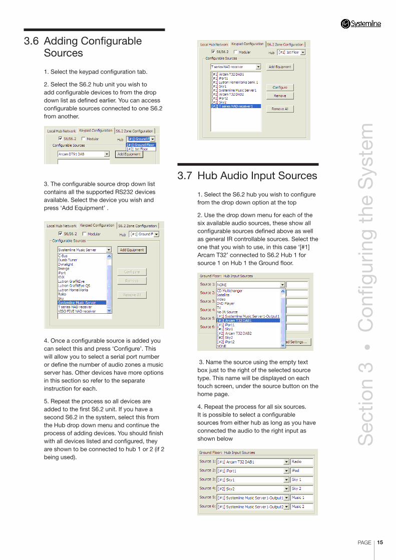
3.6 Adding Configurable Sources
1. Select the keypad configuration tab.
2. Select the S6.2 hub unit you wish to add configurable devices to from the drop down list as defined earlier. You can access configurable sources connected to one S6.2 from another.
3. The configurable source drop down list contains all the supported RS232 devices available. Select the device you wish and press ‘Add Equipment’ .
4. Once a configurable source is added you can select this and press ‘Configure’. This will allow you to select a serial port number or define the number of audio zones a music server has. Other devices have more options in this section so refer to the separate instruction for each.
5. Repeat the process so all devices are added to the first S6.2 unit. If you have a second S6.2 in the system, select this from the Hub drop down menu and continue the process of adding devices. You should finish with all devices listed and configured, they are shown to be connected to hub 1 or 2 (if 2 being used).
3.7 Hub Audio Input Sources
1. Select the S6.2 hub you wish to configure from the drop down option at the top
2. Use the drop down menu for each of the six available audio sources, these show all configurable sources defined above as well as general IR controllable sources. Select the one that you wish to use, in this case ‘[#1] Arcam T32’ connected to S6.2 Hub 1 for source 1 on Hub 1 the Ground floor.
3. Name the source using the empty text box just to the right of the selected source type. This name will be displayed on each touch screen, under the source button on the home page.
4. Repeat the process for all six sources. It is possible to select a configurable sources from either hub as long as you have connected the audio to the right input as shown below

PAGE 16
Sec
tion
3 •
Con
figur
ing
the
Sys
tem
16 across two pages). Please refer to the separate instructions for the lighting system you are using.
7 You can select a defined configurable temperature control system to be controlled from the selected keypad in the drop down box and then further configure the options. Please refer to the separate instructions for the heating / cooling system you are using.
8. You can add a complete LRN7 .qrc file here if you require IR control of main or local sources. Browse to the saved file in the correct folder that you have saved it to.
9. You can define a local input by selecting an option from the drop down list and then label it with a name of your choice which is then shown on the touch screen home page. If you have defined a configurable AV receiver you can select this for one wired touch screen and one wireless junction box, so that zone uses this as an amplifier via RS232 control.
3.9 Uploading keypad and wireless junction box configuration files
1. You can select a number of keypads to upload in one session by pressing the ‘Select Keypads’ box and then ticking the ones you wish to upload.
2. Press ‘Upload’ to load in a complete file including IR.
3. Press ‘Upload Without IR’ to upload a file without the .qrc file
3.8 Keypad Configuration Profile
1. In the ‘Selected Configuration Profile’ use the drop down box to select a keypad or wireless junction box address that has been previously defined.
2. Tick the correct Volume control box, either ‘Systemline’ for standard S6.2 zones where the S6.2 unit is controlling the volume or ‘IR’ where another amplifier is control volume using a learnt IR code.
3. You can add keypads or junction boxes manually by selecting an address number and pressing ‘Add New’. Make sure you have selected the correct S6.2 Hub first before adding
4. You can add or change the description of each keypad in the profile section as well as choosing the type of device associated with the address in the drop down box as shown below.
5. You can determine the wireless zones that can be controlled by a Wireless Commander associated with the profile by pressing the ‘Wireless Zone Control’ box and ticking the available wireless junction box’s in the system.
6. You can select a defined configurable lighting system to be controlled from the selected keypad in the drop down box and then further configure each button (up to

PAGE 17
Sec
tion
4 •
Tou
chsc
reen
Set
tings
4. Press ‘Upload Wireless Keypad’ to upload a directly USB connected Wireless Commander, as long as you have selected a wireless junction box.
3.10 Configuring audio Zone Settings
1. Select the S6.2 Zone Configuration Tab. You can configure the turn on volume, bass, treble, balance and maximum volume for each zone together with party mode options. S6.2 also has options for the supported video matrix switch and each of its IR outputs.
2. Start by naming all the audio zones for each S6.2 unit.
3. Select each zone in the Zone Configuration section and adjust the following parameters
a) Turn on volume. Each time the zone is switched on it will turn onto this value, the slider represents the same volume scale as the touch screen
b) Maximum volume. This can be used to limit the maximum volume of the zone, it cannot be any less than the turn on volume.
c) Bass EQ. Turn the bass up or down to suit the room and speakers.
d) Treble EQ. Turn the treble up or down to suite the room and speakers
e) Balance. You can offset the stereo signal to the left or right.
f) Fixed Volume. This will set the turn on volume to 30 and disable any volume
adjustment; this is used with AV receivers which alter the volume.
g) Party Mode Group. Tick this box if you wish the zone to react to any party mode command or be able to send a party command. A party command will turn all party zones to a particular source.
4. You can select a supported RS232 controlled video matrix switch by selecting between HDMI 4x8 or any Kramer video matrix switch.
5. You can determine which video input will be selected when any of the six audio inputs on S6.2 is selected. For example when S6.2 audio input 3 is selected from a zone it could select video input 1 if you wish.
6. You can adjust the IR modulation frequency for each IR socket output. Most IR controlled sources work well using 36KHz frequency but occasionally a different frequency will work better.
Bang and Olufsen source equipment use 455KHz
Sky Digi boxes use 36KHz
Sony use 40Khz
We cannot produce a definitive list, you should find that Sony source equipment happily works at 36KHz but we have provided the option to change this if needed.

PAGE 18
Sec
tion
4 •
Tou
chsc
reen
Set
tings
3.12 Loading Previously Saved .snc Files
Click on the ‘load’ button and select the required ‘.snc’ file.
3.11 Saving Configurations
You can now save your settings by clicking the ‘Save Settings As...’ button.
1. This creates a ‘.snc’ file which can be labelled with the customer’s name. Any further changes you make, just click the ‘Save’ button to save any changes.
Note: You can use this feature both to save customer settings and to create program templates. For example, you may commonly use a Sky Satellite receiver and Systemline Music Server, but use different DVD players. In this instance, the template would simply consist of the saved settings for the Sky and Systemline products. This can then be loaded as a default, leaving you to just add the customer’s specific products.
2. For other zones, simply repeat the process by adding TSKs ‘02’, ‘03’ etc. Then click ‘Save Settings’ after each zone as this will be added to your newly created ‘.snc’ file.
Note: It is very important to ensure that that the correct Keypad Configuration Profile is selected as other TSKs are configured. Double check that both the keypad and the location description is correct before saving or uploading data.

PAGE 19
Sec
tion
4 •
Tou
chsc
reen
Set
tings
The Touch Screen Keypad is factory set and should not require any further adjustment.
However, the keypad can be placed into a special configuration mode allowing the user to alter the following settings:
• Contrast (which also influences the viewing angle)
• Modular address
• Touch Screen calibration
The mode is entered by touching the ‘MUTE’ button whilst holding down the ‘VOL UP’ and ‘VOL DOWN’ buttons. The screen will then change to display the configuration screen.
4.1 Contrast
There are a set of up/down buttons on the Configuration Screen that allow the contrast level to be changed. The screen contrast will change whilst the settings are altered to demonstrate the selected value. The value will only be stored if the ‘Apply’ button is touched.
4.2 Modular Address
There are a set of up/down buttons on the Configuration Screen that allow the Modular address of the keypad to be set. The value will take effect when the ‘Apply’ button is touched.
Note: A Touch Screen can only be used in a main zone (not a sub-zone), so the only time that it will be necessary to change the Modular address, is if it is within IR range of another adjacent zone. In this instance, it may be advisable to set a different Modular address to avoid accidentally controlling one zone from another.
4 Touch Screen Keypad SettingsNote: S6.2 is designed to work with colour Touch Screen Keypads.
4.3 Touch Screen Calibration
Touch Screen Calibration is required because of manufacturing tolerances between touch screens on different keypads. This potentially causes the touch area to be misaligned with the button displayed underneath. This is indicated when a button must be touched outside its bounds in order to operate.
To change the calibration, touch the ‘Calibrate Touch Screen’ button on the Configuration Screen. The screen will then change to the ‘Touch Calibration’ screen presenting two squares with crossed centres. Use a blunt stylus e.g. a matchstick to touch the centre of the cross in each of the two squares. The more accurately this can be done, the more accurate the calibration.
The screen will change to the ‘Test Calibration’ screen, demonstrating the touch response using the calibration set on the previous screen. Use the stylus to touch the centre of the boxes which should flash to indicate being touched. If calibrated correctly, the box should only flash when touched exactly on the black dot in the centre. If the test is successful, touch the ‘Apply’ button to store the settings. If unsuccessful, press the HOME button to return to the Configuration Screen.
Press the Power button to exit the configuration mode.

PAGE 20
Sec
tion
4 •
Tou
chsc
reen
Set
tings
4.4 Getting Out of Trouble
Both the Contrast and Touch Screen Calibration settings potentially allow the keypad to be configured into a state where it can no longer be used e.g. the Configuration Screen is itself rendered unusable by a badly configured setting.
For example, the contrast can be set such that the screen is unreadable and therefore finding the controls to set it back again is difficult. Likewise, the Touch Screen Calibration can be set such that the buttons can no longer be pressed, making the Configuration Screen impossible to operate.
In the event that the Configuration Screen can no longer be operated due to an incorrect setting, pressing the ‘MUTE’ button whilst on the Configuration Screen will restore factory defaults which should allow correct operation again.


Stortford Hall Industrial Park, Dunmow Road, Bishops Stortford,
Hertfordshire CM23 5GZ United Kingdom
Web: www.armourhe.co.ukEmail: [email protected]
Our policy is one of continuous product improvement, we reserve the right to change the designs and specifications without notice. All information is given in good faith. The manufacturer accepts no responsibility for errors, omissions or incorrect assumptions.
Armour Home Electronics 2010
ZINS407-ISS3-03/11/10
www. s y s t em l i n e . c o . u k
This symbol means do not dispose of as municpal waste. Re-use or recycle wherever possible. Electrical/Electronic Equipment may contain substances harmful to the environment. For environmentally sound methods of disposal, please contact your local government agency.