S4-UVN IHAR Specific Statement of Work -...
28
Transcript of S4-UVN IHAR Specific Statement of Work -...

Specific Statement of Work for the Instrument Harness
Doc. No.: GS4.ASG.UVN.SW.00028
Issue: 1.1
Date: 08.05.2013
Page: 2
© Astrium GmbH — All rights reserved
Distribution List
Specific Statement of Work for the Instrument Harness
Doc. No.: GS4.ASG.UVN.SW.00028
Issue: 1.1
Date: 08.05.2013
Page: 3
© Astrium GmbH — All rights reserved
Change Record Issue Date Sheet Description of Change
Draft 1 19-12-2012 All First draft issue of document for pre-TEB
1 22.02.2013 All First issue
1.1 08.05.2013 16 IHAR SSOW 36 reworded to clearly define baseline and option.
25 IHAR SSOW 130
IHAR SSOW 140
Need dates updated according to current project schedule (V14.E)

Specific Statement of Work for the Instrument Harness
Doc. No.: GS4.ASG.UVN.SW.00028
Issue: 1.1
Date: 08.05.2013
Page: 4
© Astrium GmbH — All rights reserved
Table of Contents
1 Introduction ............................................................................................................................... 5
1.1 Scope of the Document ......................................................................................................................... 5 1.2 Definition of the Instrument Harness ................................................................................................... 6 1.3 Scope of the Work .................................................................................................................................. 9
2 Applicable & Reference Documents ...................................................................................... 12
2.1 Project Applicable Documents ........................................................................................................... 12 2.2 Use of ECSS Standards ....................................................................................................................... 12 2.3 Reference Documents.......................................................................................................................... 12
3 Abbreviations & Terminology ................................................................................................ 13
3.1 List of Abbreviations ............................................................................................................................ 13 3.2 Definition of Terms ............................................................................................................................... 13
4 Engineering and Design ......................................................................................................... 14
4.1 Design .................................................................................................................................................... 14 4.2 Analyses ................................................................................................................................................ 16 4.3 CAD Models .......................................................................................................................................... 16
5 Development and Qualification .............................................................................................. 17
5.1 Reviews and Milestone Planning ........................................................................................................ 17 5.2 Model Philosophy ................................................................................................................................. 18 5.3 Spare Approach .................................................................................................................................... 19
6 Production Process Requirements ........................................................................................ 21
7 Verification .............................................................................................................................. 22
7.1 Specific Tests ....................................................................................................................................... 22 7.2 Verification Analyses ........................................................................................................................... 23 7.3 Verification Control Data ..................................................................................................................... 23 7.4 Documents subject to Verification Control ....................................................................................... 23
8 Delivery and Acceptance ........................................................................................................ 24
8.1 Deliverable Harness Hardware ............................................................................................................ 24 8.2 Deliverable non-flight Models ............................................................................................................. 24 8.3 Deliverable Flight Models .................................................................................................................... 25 8.4 Ground Support Equipment ................................................................................................................ 25 8.5 Delivery Requirements......................................................................................................................... 26
8.5.1 Packing .......................................................................................................................................... 26 8.5.2 Storage .......................................................................................................................................... 26 8.5.3 Transport ........................................................................................................................................ 26
8.6 Customer Undertakings ....................................................................................................................... 27 8.6.1 Customer Documents and Models ................................................................................................ 27 8.6.2 Other Customer Undertakings ....................................................................................................... 27
8.7 Harness Integration .............................................................................................................................. 27 8.8 Post Delivery Support .......................................................................................................................... 28
Specific Statement of Work for the Instrument Harness
Doc. No.: GS4.ASG.UVN.SW.00028
Issue: 1.1
Date: 08.05.2013
Page: 5
© Astrium GmbH — All rights reserved
1 Introduction
1.1 Scope of the Document
Note in advance: For simplification “Optical Instrument Module (OIM) internal and external harness” are called
“Instrument Harness (IHAR)” in this document.
This document provides the Specific Statement of Work (SSOW) for the Supplier of the Instrument Harness
(IHAR) which is defined by the Harness Requirements Specification GS4.ASG.UVN.RS.00049_2.0 including
all annexes and applicable documents. It defines the tasks of the equipment Supplier for:
The design, development, qualification, production, integration, test and delivery of the equipment.
The provision of tooling, test and support equipment, support services and transportation services to
support instrument and spacecraft assembly, integration, test and launch, associated with the
equipment operation and handling,
The preparation and delivery of documentation.
This document is part of the Supply Contract between Astrium and the equipment Supplier. Hereinafter the
equipment Supplier is referenced as “the Supplier” and the Astrium Customer as “the Customer”.
This document applies in conjunction with the "Generic Statement of Work for Supply of Equipments for S4 -
UVN Project” (GS4.ASG.UVN.SW.00008) referred to as the GSOW. The Generic Statement Of Work
amended by this Specific Statement Of Work defines the work to be performed and the deliverable items in
terms of hardware, software, documentation, services and support for the supply of the Instrument Control
Unit.
In the case of conflict with the Generic SOW, this Specific SOW shall have precedence. Tasks and
deliverables specified herein and in the Generic SOW are considered mandatory but not necessarily
exhaustive.
In addition, tasks and deliverables are categorized into baseline tasks and optional tasks. Both kinds of tasks
may occur in this SSOW. Unless not specifically identified to the contrary, all tasks and deliverables specified
hereafter shall belong to the baseline tasks.
This Specific Statement of Work (SSOW) together with the Generic SOW with all its attachments and
applicable documents and standards will become part of the Contract between Astrium and the Supplier and
all the requirements therein are applicable to the work to be performed by the Supplier.
The requirements of this SSOW shall also be made applicable to the contractually specified Lower Level
Subcontractors/Suppliers, as pertinent to their work shares. Therefore the word "Supplier" shall be interpreted
as “Supplier and Lower Level Subcontractors/Suppliers”, if not specifically restricted by appropriate
formulations. Hardware and Software from other sources, such as OTS items, shall be procured according to
the equivalent technical, quality and safety related requirements.
Specific Statement of Work for the Instrument Harness
Doc. No.: GS4.ASG.UVN.SW.00028
Issue: 1.1
Date: 08.05.2013
Page: 6
© Astrium GmbH — All rights reserved
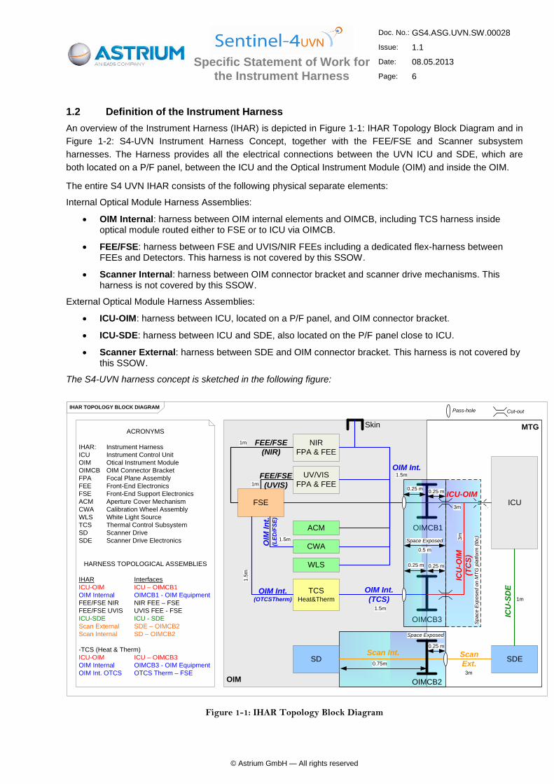
1.2 Definition of the Instrument Harness
An overview of the Instrument Harness (IHAR) is depicted in Figure 1-1: IHAR Topology Block Diagram and in
Figure 1-2: S4-UVN Instrument Harness Concept, together with the FEE/FSE and Scanner subsystem
harnesses. The Harness provides all the electrical connections between the UVN ICU and SDE, which are
both located on a P/F panel, between the ICU and the Optical Instrument Module (OIM) and inside the OIM.
The entire S4 UVN IHAR consists of the following physical separate elements:
Internal Optical Module Harness Assemblies:
OIM Internal: harness between OIM internal elements and OIMCB, including TCS harness inside optical module routed either to FSE or to ICU via OIMCB.
FEE/FSE: harness between FSE and UVIS/NIR FEEs including a dedicated flex-harness between FEEs and Detectors. This harness is not covered by this SSOW.
Scanner Internal: harness between OIM connector bracket and scanner drive mechanisms. This harness is not covered by this SSOW.
External Optical Module Harness Assemblies:
ICU-OIM: harness between ICU, located on a P/F panel, and OIM connector bracket.
ICU-SDE: harness between ICU and SDE, also located on the P/F panel close to ICU.
Scanner External: harness between SDE and OIM connector bracket. This harness is not covered by this SSOW.
The S4-UVN harness concept is sketched in the following figure:
MTG
OIM
IHAR TOPOLOGY BLOCK DIAGRAM
UV/VIS
FPA & FEE
NIR
FPA & FEE
FSE
SD SDE
ICU
TCSHeat&Therm
ACM
CWA
WLS
OIMCB1
ICU-OIM
OIM Int.
ICU
-SD
E
Scan
Ext.
Scan Int.
ACRONYMS
IHAR: Instrument Harness
ICU Instrument Control Unit
OIM Otical Instrument Module
OIMCB OIM Connector Bracket
FPA Focal Plane Assembly
FEE Front-End Electronics
FSE Front-End Support Electronics
ACM Aperture Cover Mechanism
CWA Calibration Wheel Assembly
WLS White Light Source
TCS Thermal Control Subsystem
SD Scanner Drive
SDE Scanner Drive Electronics
HARNESS TOPOLOGICAL ASSEMBLIES
IHAR Interfaces
ICU-OIM ICU – OIMCB1
OIM Internal OIMCB1 - OIM Equipment
FEE/FSE NIR NIR FEE – FSE
FEE/FSE UVIS UVIS FEE - FSE
ICU-SDE ICU - SDE
Scan External SDE – OIMCB2
Scan Internal SD – OIMCB2
-TCS (Heat & Therm)
ICU-OIM ICU – OIMCB3
OIM Internal OIMCB3 - OIM Equipment
OIM Int. OTCS OTCS Therm – FSE
OIMCB2
OIMCB3
OIM Int.
(TCS)
ICU
-OIM
(TC
S)
FEE/FSE
(NIR)
FEE/FSE
(UVIS)
OIM Int.(OTCSTherm)
Skin
OIM
In
t.(L
ED
/FS
E)
1m
1m
1.5
m
1.5m
0.75m
1.5m
1.5m
3m
3m
1m
3m
Sp
ace
Exp
ose
d o
n M
TG
pla
tfo
rm (
tbc)
Space Exposed
Cut-outPass-hole
Space Exposed
0.5 m
0.25 m
0.25 m
0.25 m
0.25 m
0.25 m
Figure 1-1: IHAR Topology Block Diagram

Specific Statement of Work for the Instrument Harness
Doc. No.: GS4.ASG.UVN.SW.00028
Issue: 1.1
Date: 08.05.2013
Page: 7
© Astrium GmbH — All rights reserved
Also harness shall include all the necessary elements, as tie-bases, stand-offs, attachments, connector-
brackets etc., to support integration of the OIM internal harness.
Notes:
1. All lengths are aproximate.
2. Design baseline does not consider the whole ICU-OIM harness assembly on the MTG platform (aprox. 3m length) space exposed. The design baseline space exposed spot is at I/F connector bracket as depicted. The space exposed ICU-OIM harness assembly on the MTG platform (aprox. 3m length) is a design solution currently TBC.
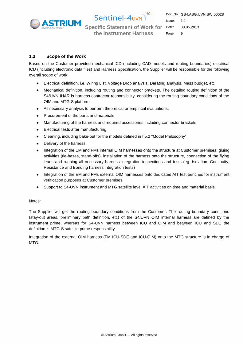
Figure 1-2 gives a more detailed harness overview, which also shows the implemented redundancies and resulting cross-coupling.
95

Specific Statement of Work for the Instrument Harness
Doc. No.: GS4.ASG.UVN.SW.00028
Issue: 1.1
Date: 08.05.2013
Page: 8
© Astrium GmbH — All rights reserved
Aperture
Cover
Drive N
Scanner
Drives
N
S4-UVN
ICU
N
SDE N
P/F Harness
OIM
OIM Internal Harness N
OIM Internal Harness R
ICU - OIM Harness N
ICU - OIM Harness R
ICU - SDE Harness N
ICU - SDE Harness R
Status 07.11.2012
OIM Connector
Bracket3 x Launch
Lock Device
N + R
Skin Connector
Aperture
Cover
Drive R
Scanner
Drives
R
S4-UVN
ICU
R
SDE R
ICU
R P
/F In
terf
ace
ICU
N P
/F In
terf
ace
Electronics Panel at P/F Side
FEE/FSE S/S Harness N
FEE/FSE S/S Harness R
Scanner S/S Harness N
Scanner S/S Harness R
CAS
UV/VIS
FEE & Detector
FSE N
FSE R
FEE DC Supplies
OTCS Tmp Acqu
NIR
FEE & Detector
Cal Drive N
LEDs N WLS N
CAS Cal Drive R
LEDs R WLS R
OTCS
Thermistor
Triples
OTCS Heaters R
A
OTCS Heaters N
B
C
HK Thermistors
Control Thermistors
L/STCS Heaters N
N
L/STCS Heaters R
R
N RMonitoring Thermistors
HK Thermistors
N N……….
R R……….
Figure 1-2: S4-UVN Instrument Harness Concept
Besides the IHAR the Figure 1-2 also shows the
● FEE/FSE S/S Harness, which is part of the FEE/FSE subsystem
● Scanner S/S Harness, which is part of the scanner subsystem
92
Specific Statement of Work for the Instrument Harness
Doc. No.: GS4.ASG.UVN.SW.00028
Issue: 1.1
Date: 08.05.2013
Page: 9
© Astrium GmbH — All rights reserved
1.3 Scope of the Work
Based on the Customer provided mechanical ICD (including CAD models and routing boundaries) electrical
ICD (including electronic data files) and Harness Specification, the Supplier will be responsible for the following
overall scope of work:
● Electrical definition, i.e. Wiring List, Voltage Drop analysis, Derating analysis, Mass budget, etc
● Mechanical definition, including routing and connector brackets. The detailed routing definition of the
S4/UVN IHAR is harness contractor responsibility, considering the routing boundary conditions of the
OIM and MTG-S platform.
● All necessary analysis to perform theoretical or empirical evaluations.
● Procurement of the parts and materials
● Manufacturing of the harness and required accessories including connector brackets
● Electrical tests after manufacturing.
● Cleaning, including bake-out for the models defined in §5.2 "Model Philosophy"
● Delivery of the harness.
● Integration of the EM and FMs internal OIM harnesses onto the structure at Customer premises: gluing
activities (tie-bases, stand-offs), installation of the harness onto the structure, connection of the flying
leads and running all necessary harness integration inspections and tests (eg. Isolation, Continuity,
Resistance and Bonding harness integration tests)
● Integration of the EM and FMs external OIM harnesses onto dedicated AIT test benches for instrument
verification purposes at Customer premises.
● Support to S4-UVN instrument and MTG satellite level AIT activities on time and material basis.
Notes:
The Supplier will get the routing boundary conditions from the Customer. The routing boundary conditions
(stay-out areas, preliminary path definition, etc) of the S4/UVN OIM internal harness are defined by the
instrument prime, whereas for S4-UVN harness between ICU and OIM and between ICU and SDE the
definition is MTG-S satellite prime responsibility.
Integration of the external OIM harness (FM ICU-SDE and ICU-OIM) onto the MTG structure is in charge of
MTG.

Specific Statement of Work for the Instrument Harness
Doc. No.: GS4.ASG.UVN.SW.00028
Issue: 1.1
Date: 08.05.2013
Page: 10
© Astrium GmbH — All rights reserved
The workload breakdown for a FM harness in terms of points of the Instrument Harness (IHAR) is as follows
(SDE and FSE/FEE excluded):
Note: Model Philosophy in described at § 5.2 Model Philosophy
Flight Model
Each Flight Model is expected to entail following workload and connector and cable needs:
Module and harness assembly characteristics Manufacturing Points Integration Points
TOTAL Wire Shield Total cable Flying Leads (FL)
External OIM / Internal MTG
Overshielded 3D Harness
Assembly (no separated bundles)
Branches segregated per spec §4.1.1
1800 600 2400 0 2400
Internal OIM
Overshielded 3D Harness
Assembly (no separated bundles)
Branches segregated per spec §4.1.1
1500 600 2100 900 3000
Totals 4500 900 5400
Table 1-1: FM Harness Assembly Point Budget
In order to allow assessment of the wires and connections needed for the IHAR, a preliminary FM harness
connector and cable list is hereafter provided (SDE and FSE/FEE excluded).
Internal OIM Harness External OIM / Internal MTG
Connector Part Number Qty** Connector Part Number Qty**
340100201B D A MA-15P-NMB-FO 2 340100201B D A MA-15S-NMB-FO 2
340100201B D B MA-25P-NMB-FO 2 340100201B D B MA-25P-NMB-FO 4
340100201B D B MA-25S-NMB-FO 4 340100201B D B MA-25S-NMB-FO 2
340100201B D D MA-50P-NMB-FO 6 340100201B D D MA-50P-NMB-FO 8
340100201B D D MA-50S-NMB-FO 2 340100201B D D MA-50S-NMB-FO 6
340100201B D E MA-09P-NMB-FO 2 340100201B D E MA-09P-NMB-FO 4
340100201B D E MA-09S-NMB-FO 10 340100201B D E MA-09S-NMB-FO 2
340100202B D C MA-62P-NMB-FO 3 340100202B D D MA-78P-NMB-FO 4
340100202B D C MA-62S-NMB-FO 3 340100202B D D MA-78S-NMB-FO 2
340100202B D D MA-78S-NMB-FO 2 340100202B D F MA-104P-NMB-FR172-FO 2
340100202B D F MA-104P-NMB-FR172-FO 3
340100202B D F MA-104S-NMB-FR172-FO 2
MDM-09P 4 MDM-09S 4
**For quotation consider 1 connector more of each.
**For quotation consider 1 connector more of each.
Table 1-2: Connector BOM
Internal OIM Harness External OIM / Internal MTG
Cable Part Number Length* Cable Part Number Length*
SBL22 (3902002 21B) 6 SBL22 (3902002 21B) 10
SBL28 (3902002 23B) 36 SBL28 (3902002 23B) 94

Specific Statement of Work for the Instrument Harness
Doc. No.: GS4.ASG.UVN.SW.00028
Issue: 1.1
Date: 08.05.2013
Page: 11
© Astrium GmbH — All rights reserved
SPW28 (3902003 01B) 12 SPW28 (3902003 01B) 16
STP26 (3901002 46B) 72 STP26 (3901002 46B) 168
STP28 (3901002 65B) 6 STP28 (3901002 65B) 10
T3C26 (3901002 36B) 6 T3C26 (3901002 36B) 10
TP22 (3901002 33B) 3 TP20 (3901002 34B) 204
TP24 (3901002 32B) 30 TP22 (3901002 33B) 7
TP28 (3901002 62B) 84 TP24 (3901002 32B) 82
TP28 (3901002 62B) 368
*Total length in [m] For quotation consider 10% additional length of each.
*Total length in [m] For quotation consider 10% additional length of each.
Legend SBL: Shielded Balance Line STP: Shielded Twisted Pair SPW: SpaceWire T3C: Twisted 3-Core TP: Twisted Pair
Legend SBL: Shielded Balance Line STP: Shielded Twisted Pair SPW: SpaceWire T3C: Twisted 3-Core TP: Twisted Pair
Table 1-3: Cable BOM
The prime objectives shall be minimised mass and high level of validation with respect to the need of reliability
and availability for the S4-UVN instrument programme.
Engineering Model:
The size of the EM is 50% of the FM (includes both Internal OIM and External OIM / Internal MTG)

Specific Statement of Work for the Instrument Harness
Doc. No.: GS4.ASG.UVN.SW.00028
Issue: 1.1
Date: 08.05.2013
Page: 12
© Astrium GmbH — All rights reserved
2 Applicable & Reference Documents
2.1 Project Applicable Documents
The documents applicable to the required activities and deliverables as relevant for the specific tasks of the
Supplier of the equipment in subject are identified in the Contractual Baseline Document List (CBDL) ref.
GS4.ASG.UVN.LI.00096. The CBDL defines also the order of precedence of these documents.
2.2 Use of ECSS Standards
The Suppliers activities, processes and documentation shall be based on and respectively comply with ECSS
standards of issues and revisions as specified in this document and the Applicable Documents related to
technical, PA, and managerial requirements.
2.3 Reference Documents
The following documents present further background information with respect to the overall context of the S-4
UVN and generic aspects related to the equipment supply.
RD Title Reference
none

Specific Statement of Work for the Instrument Harness
Doc. No.: GS4.ASG.UVN.SW.00028
Issue: 1.1
Date: 08.05.2013
Page: 13
© Astrium GmbH — All rights reserved
3 Abbreviations & Terminology
3.1 List of Abbreviations
Refer to AD-26 and AD-26a of the applicable Contract Baseline Documents List.
3.2 Definition of Terms
Refer to section 3.2 of the applicable GSOW.
Specific Statement of Work for the Instrument Harness
Doc. No.: GS4.ASG.UVN.SW.00028
Issue: 1.1
Date: 08.05.2013
Page: 14
© Astrium GmbH — All rights reserved
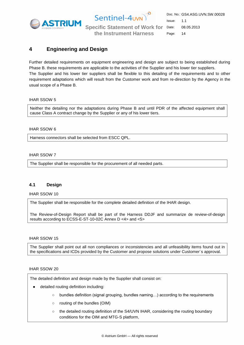
4 Engineering and Design
Further detailed requirements on equipment engineering and design are subject to being established during
Phase B. these requirements are applicable to the activities of the Supplier and his lower tier suppliers.
The Supplier and his lower tier suppliers shall be flexible to this detailing of the requirements and to other
requirement adaptations which will result from the Customer work and from re-direction by the Agency in the
usual scope of a Phase B.
IHAR SSOW 5
Neither the detailing nor the adaptations during Phase B and until PDR of the affected equipment shall cause Class A contract change by the Supplier or any of his lower tiers.
IHAR SSOW 6
Harness connectors shall be selected from ESCC QPL.
IHAR SSOW 7
The Supplier shall be responsible for the procurement of all needed parts.
4.1 Design
IHAR SSOW 10
The Supplier shall be responsible for the complete detailed definition of the IHAR design.
The Review-of-Design Report shall be part of the Harness DDJF and summarize de review-of-design results according to ECSS-E-ST-10-02C Annex D <4> and <5>
IHAR SSOW 15
The Supplier shall point out all non compliances or inconsistencies and all unfeasibility items found out in the specifications and ICDs provided by the Customer and propose solutions under Customer´s approval.
IHAR SSOW 20
The detailed definition and design made by the Supplier shall consist on:
● detailed routing definition including:
○ bundles definition (signal grouping, bundles naming…) according to the requirements
○ routing of the bundles (OIM)
○ the detailed routing definition of the S4/UVN IHAR, considering the routing boundary
conditions for the OIM and MTG-S platform,
Specific Statement of Work for the Instrument Harness
Doc. No.: GS4.ASG.UVN.SW.00028
Issue: 1.1
Date: 08.05.2013
Page: 15
© Astrium GmbH — All rights reserved
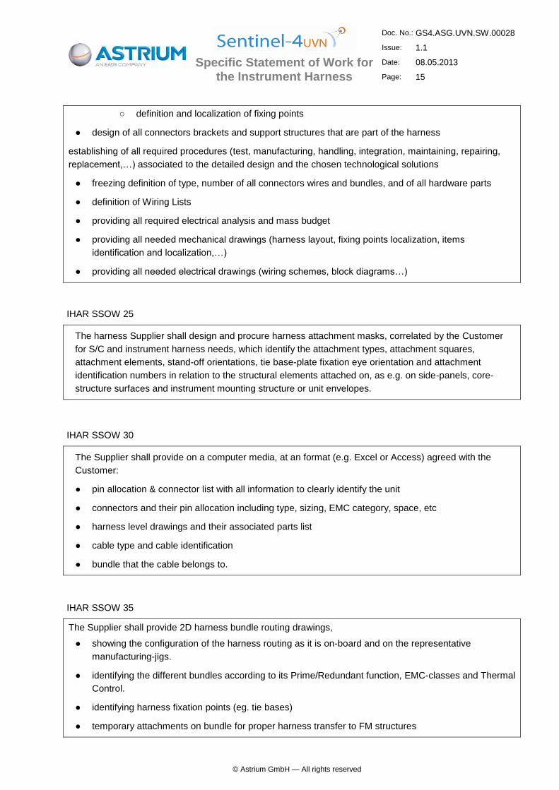
○ definition and localization of fixing points
● design of all connectors brackets and support structures that are part of the harness
establishing of all required procedures (test, manufacturing, handling, integration, maintaining, repairing,
replacement,…) associated to the detailed design and the chosen technological solutions
● freezing definition of type, number of all connectors wires and bundles, and of all hardware parts
● definition of Wiring Lists
● providing all required electrical analysis and mass budget
● providing all needed mechanical drawings (harness layout, fixing points localization, items
identification and localization,…)
● providing all needed electrical drawings (wiring schemes, block diagrams…)
IHAR SSOW 25
The harness Supplier shall design and procure harness attachment masks, correlated by the Customer
for S/C and instrument harness needs, which identify the attachment types, attachment squares,
attachment elements, stand-off orientations, tie base-plate fixation eye orientation and attachment
identification numbers in relation to the structural elements attached on, as e.g. on side-panels, core-
structure surfaces and instrument mounting structure or unit envelopes.
IHAR SSOW 30
The Supplier shall provide on a computer media, at an format (e.g. Excel or Access) agreed with the
Customer:
● pin allocation & connector list with all information to clearly identify the unit
● connectors and their pin allocation including type, sizing, EMC category, space, etc
● harness level drawings and their associated parts list
● cable type and cable identification
● bundle that the cable belongs to.
IHAR SSOW 35
The Supplier shall provide 2D harness bundle routing drawings,
● showing the configuration of the harness routing as it is on-board and on the representative
manufacturing-jigs.
● identifying the different bundles according to its Prime/Redundant function, EMC-classes and Thermal
Control.
● identifying harness fixation points (eg. tie bases)
● temporary attachments on bundle for proper harness transfer to FM structures
Specific Statement of Work for the Instrument Harness
Doc. No.: GS4.ASG.UVN.SW.00028
Issue: 1.1
Date: 08.05.2013
Page: 16
© Astrium GmbH — All rights reserved
IHAR SSOW 36
Regarding requirement IHARS-1356 of AD-3 for overshielding of the OIM external harness, the Tenderer shall
quote the following 2 scenarios on the assumption that the entire MTG harness needs overshielding in:
Baseline:
OIM external harness overshielded with braid/mesh.
Option:
OIM external harness overshielded with Al foil.
4.2 Analyses
IHAR SSOW 40
Together with the analyses required in the Generic Statement of Work (GSOW) and in the CBDL the following analyses shall be provided by the Supplier to demonstrate suitability for the S-4 UVN mission
Reliability analysis (A)
Voltage Drop and Resistance Analysis (B)
Worst Case Analysis (A)
Brackets Mechanical / Structural Analysis (A)
Analysis categorized (A) shall be provided as requested by the Customer for the respective reviews and updated as necessary to always reflect the latest HW implementation.
Analysis categorized (B) shall be provided as requested by the Customer for the respective reviews and updated as necessary to always reflect the latest HW implementation and shall be correlated with respective test results.
4.3 CAD Models
IHAR SSOW 45
The harness Supplier shall implement in the CAD model, which is provided by the Customer, all harness bundles, connectors, stand-offs, attachments, brackets, connector-bracktes and return the CAD model in regular stages to Customer. The data file format is CatiaV5R19.
Specific Statement of Work for the Instrument Harness
Doc. No.: GS4.ASG.UVN.SW.00028
Issue: 1.1
Date: 08.05.2013
Page: 17
© Astrium GmbH — All rights reserved
5 Development and Qualification
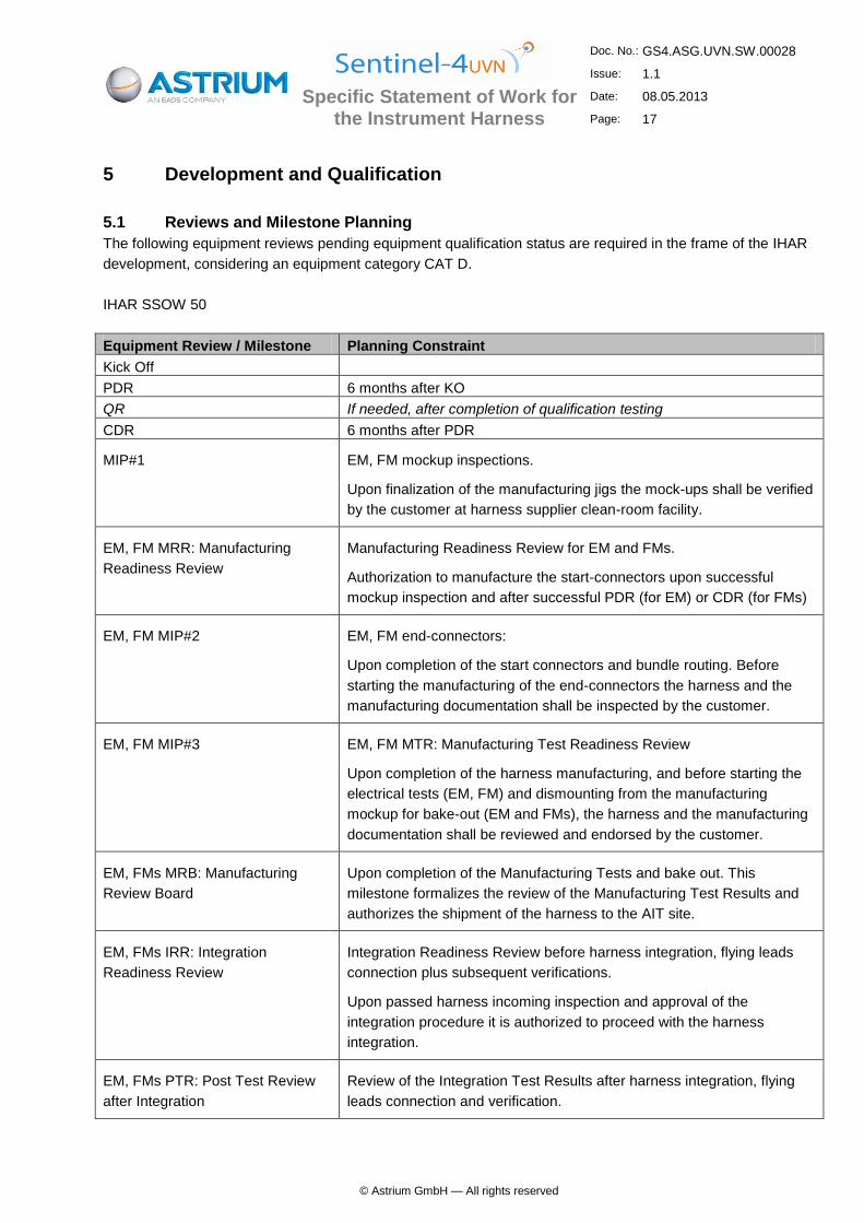
5.1 Reviews and Milestone Planning
The following equipment reviews pending equipment qualification status are required in the frame of the IHAR
development, considering an equipment category CAT D.
IHAR SSOW 50
Equipment Review / Milestone Planning Constraint
Kick Off
PDR 6 months after KO
QR If needed, after completion of qualification testing
CDR 6 months after PDR
MIP#1 EM, FM mockup inspections.
Upon finalization of the manufacturing jigs the mock-ups shall be verified
by the customer at harness supplier clean-room facility.
EM, FM MRR: Manufacturing
Readiness Review
Manufacturing Readiness Review for EM and FMs.
Authorization to manufacture the start-connectors upon successful
mockup inspection and after successful PDR (for EM) or CDR (for FMs)
EM, FM MIP#2 EM, FM end-connectors:
Upon completion of the start connectors and bundle routing. Before
starting the manufacturing of the end-connectors the harness and the
manufacturing documentation shall be inspected by the customer.
EM, FM MIP#3 EM, FM MTR: Manufacturing Test Readiness Review
Upon completion of the harness manufacturing, and before starting the
electrical tests (EM, FM) and dismounting from the manufacturing
mockup for bake-out (EM and FMs), the harness and the manufacturing
documentation shall be reviewed and endorsed by the customer.
EM, FMs MRB: Manufacturing
Review Board
Upon completion of the Manufacturing Tests and bake out. This
milestone formalizes the review of the Manufacturing Test Results and
authorizes the shipment of the harness to the AIT site.
EM, FMs IRR: Integration
Readiness Review
Integration Readiness Review before harness integration, flying leads
connection plus subsequent verifications.
Upon passed harness incoming inspection and approval of the
integration procedure it is authorized to proceed with the harness
integration.
EM, FMs PTR: Post Test Review
after Integration
Review of the Integration Test Results after harness integration, flying
leads connection and verification.

Specific Statement of Work for the Instrument Harness
Doc. No.: GS4.ASG.UVN.SW.00028
Issue: 1.1
Date: 08.05.2013
Page: 18
© Astrium GmbH — All rights reserved
Equipment Review / Milestone Planning Constraint
EM, FMs DRB: Formal Delivery Review Board and Acceptance of the EIDP for the
already integrated harness.
Table 5-1: Reviews and Milestone Planning for IHAR
The content of the respective data packages shall be compliant with the DRL and shall be agreed with the Customer in due time before the respective review, whereby the Customer shall provide the review procedure.
5.2 Model Philosophy
The harness contribution to the S4 model philosophy is the following:
Model Assemblies * Functionality Quality TVAC
Compatible Bake-out Overshielding
EM Internal
External Nominal
- MIL connectors
- Flight manufacturing techniques.
- Flight representative backshells,
overshielding and grounding.
Yes
Internal:
Yes
External: No
Spec
FMs Internal
External Full Flight Yes
Internal:
Yes
External: No
Spec
Table 5-2: Harness Model Characteristics
* Note:
Internal means internal OIM
External means external OIM / internal MTG

Specific Statement of Work for the Instrument Harness
Doc. No.: GS4.ASG.UVN.SW.00028
Issue: 1.1
Date: 08.05.2013
Page: 19
© Astrium GmbH — All rights reserved
Engineering model (EM):
EM harness shall consist of the nominal networks (non-redundant equipment configuration, nominal harness
only) of the internal OIM and external OIM/internal MTG harnesses including all its ancillary parts (e.g.
connector brackets, fixations and similar).
The EM Harness model will be used for electrical performance, electromagnetic compatibility and functional
tests. The EM harness model shall consist on an electrically and electromagnetically flight representative
harness. Routing, shielding, overshielding, backshells and bonding shall be therefore flight representative.
The EM harness model shall perform in clean-room as well as in TVAC (OQM). Components shall be therefore
TVAC environment compatible.
Internal OIM harness including all its ancillary parts shall be submitted to bake out prior to delivery.
2 x Flight Models (FM1 + FM2):
The Harness S/S shall consist of the full networks of the internal OIM and external OIM/internal MTG
harnesses including all its ancillary parts (e.g. connector brackets, fixations and similar).
The FM1 and FM2 will be flight models, incorporating only parts, materials and processes which have been
qualified to contractually agreed standards. The manufacturing shall be done with all the PA provisions.
Internal OIM harness including all its ancillary parts shall be submitted to bake out prior to delivery.
5.3 Spare Approach
IHAR SSOW 55
The Supplier shall implement a spare/repair/attrition philosophy to ensure that the program schedule
constraints are met during both integration and testing phase.
Non-deliverable spare batch:
The contractor is requested to propose and implement a suitable approach to guarantee the immediate
availability of parts (eg. connectors, back shells, etc) and materials for carrying out modifications on the
harness covering minimum the 10% of the total assembly after delivery. The contractor shall be able to provide
sufficient spare parts to ensure that any repair or modification is possible without delay due to delivery time of
parts and materials.
Deliverable spare kit:
In addition to the above requested spare part availability, the contractor shall deliver a spare kit containing
backup and non-reusable parts and materials necessary in case of repairing or modifications during the AIT
activities. The contents of the spare kit shall be computed extra to the nominal harness delivery.
At least following items and quantities shall be part of the deliverable spare kit :
Item Quantity per type Minimum quantity per type
Saver (only for FMs) 10% 1 piece

Specific Statement of Work for the Instrument Harness
Doc. No.: GS4.ASG.UVN.SW.00028
Issue: 1.1
Date: 08.05.2013
Page: 20
© Astrium GmbH — All rights reserved
Item Quantity per type Minimum quantity per type
EMC cap 10% 1 piece
Screw lock
(male or female + washers or clip) 10% 2 pieces
Tie-rap + protective layer 25% 250 pieces
Al foil 2 rolls 2 rolls
Yellow Kapton 2 rolls 2 rolls
Bonding wire 10% 10m
Bonding strap 20% 2 pieces
Ring tonge terminal 20% 2 pieces
Table 5-3: Deliverable spare kit
The contractor can add another non-reusable materials and parts deemed necessary in case of dismounting
and reintegration operations during AIT activities (eg. due to unit dismounting or other repairing)
IHAR SSOW 60
The Supplier shall deliver the spare / repair kit together with each EM and FMs.

Specific Statement of Work for the Instrument Harness
Doc. No.: GS4.ASG.UVN.SW.00028
Issue: 1.1
Date: 08.05.2013
Page: 21
© Astrium GmbH — All rights reserved
6 Production Process Requirements
Refer to the applicable Contract Baseline Documents List.

Specific Statement of Work for the Instrument Harness
Doc. No.: GS4.ASG.UVN.SW.00028
Issue: 1.1
Date: 08.05.2013
Page: 22
© Astrium GmbH — All rights reserved
7 Verification
7.1 Specific Tests
IHAR SSOW 70
The Supplier shall foresee, plan and execute all inspections and tests necessary to demonstrate complete close-out of applicable requirements. Any specific tests i.e. tests that are not per se part of engineering model, qualification or acceptance testing shall be identified at equipment PDR.
IHAR SSOW 75
The following test matrix applies:
Category D
Tests EM First FM Other FM's
Physical properties X X (*) X
Isolation, continuity
and resistance tests X X X
Performance tests on system level on system level on system level
Sine -- on system level on system level --
QSL -- -- --
Shock (3) -- -- --
(Random)
Acoustic -- on system level on system level
TV -- on system level on system level
Bonding & isolation X X X
ESD on system level -- --
CE on system level on system level
CS on system level on system level on system level
RE -- on system level --
RS -- on system level --
EMC Transient -- -- --
(*) = includes CoG / MoI -- No test required
Table 7-1: Instrument Harness Test Matrix
IHAR SSOW 80
On completion of the EM and FMs harnesses, the assemblies shall be weighed and this figure reported to the Customer. Intermediately, the harness mass shall be reported in the frame of all monthly harness progress reports on a harness bundle basis inclusive detailed mass table (excel-file) of selected harness items.
IHAR SSOW 85
Both for EM and FMs harnesses, the tie bases, cable ties, harness supporting brackets, connector-brackets, expected harness protection H/W and any other on-board ancillary part shall be weighed separately and the total reported to the Customer.
Specific Statement of Work for the Instrument Harness
Doc. No.: GS4.ASG.UVN.SW.00028
Issue: 1.1
Date: 08.05.2013
Page: 23
© Astrium GmbH — All rights reserved
7.2 Verification Analyses
IHAR SSOW 90
The Supplier shall foresee, plan and execute any particular analysis necessary to demonstrate complete close-out of applicable requirements. Any particular analysis in addition to those already specified shall be identified at equipment PDR.
IHAR SSOW 95
Mass estimates for each sub-harness identified by the harness product tree ID and all other delivered hardware shall be provided to the Customer according to the harness delivery schedule & milestones.
7.3 Verification Control Data
IHAR SSOW 100
The Supplier shall provide the Verification Control Document of the applicable requirements. The exact exchange format as well as exchange of working copies will be defined by the Customer.
For verification control data exchange either DOORS or another agreed electronic format (e.g. MS Excel) shall
be foreseen.
7.4 Documents subject to Verification Control
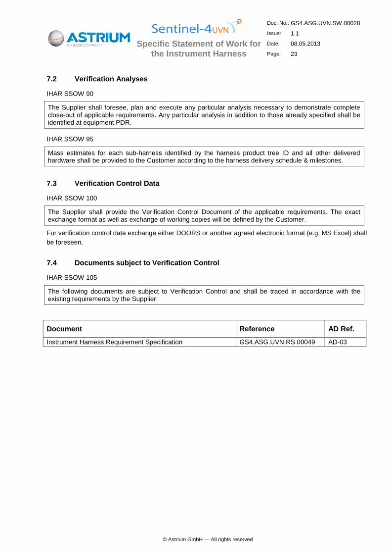
IHAR SSOW 105
The following documents are subject to Verification Control and shall be traced in accordance with the existing requirements by the Supplier:
Document Reference AD Ref.
Instrument Harness Requirement Specification GS4.ASG.UVN.RS.00049 AD-03

Specific Statement of Work for the Instrument Harness
Doc. No.: GS4.ASG.UVN.SW.00028
Issue: 1.1
Date: 08.05.2013
Page: 24
© Astrium GmbH — All rights reserved
8 Delivery and Acceptance
Further to the Contract and GSOW the following specific requirements apply:
8.1 Deliverable Harness Hardware
IHAR SSOW 110
The Supplier shall deliver all the bundles and connectors constituting the harness, with all needed
accessories mounted on harness or separate delivered:
all connectors, wires strain relief clamp and EMC backshells, shields connection grids, metallic closing shells, and associated fixing devices
connectors locking devices (separate delivered, not mounted)
cables and overshields
bundles fixation devices: fasteners, cable clamps, ty-bases, ty-raps, ty-bases supports, glued or riveted cables supports, adhesive tapes…
all connector brackets and support structures that are part of the harness
SAFE plugs
connector savers for receptacle connectors on connector brackets
connector protective covers (ESD qualified for electrostatic discharge) against dust or mechanical damage (mounted on connectors)
identification parts for bundles, connectors, plugs, mechanical parts.
edges protections
all other needed accessories and harness consumable.
IHAR SSOW 115
For EMs, all hardware is not hi-rel, connectors shall be gold plated.
For Flight Models, hi-rel parts shall be used.
IHAR SSOW 120
All harness fixation and attachment H/W inclusive bolts, washers, nuts and spacers and shims shall be procured by the harness Supplier and shipped to Customer AIT facilities at delivery of the harness.
8.2 Deliverable non-flight Models
IHAR SSOW 125
The Supplier shall deliver the non flight models after successful completion of the respective test campaign and authorization by the Instrument Prime.
Delivery dates and locations for non-flight equipment are given in Table 8-1
Specific Statement of Work for the Instrument Harness
Doc. No.: GS4.ASG.UVN.SW.00028
Issue: 1.1
Date: 08.05.2013
Page: 25
© Astrium GmbH — All rights reserved
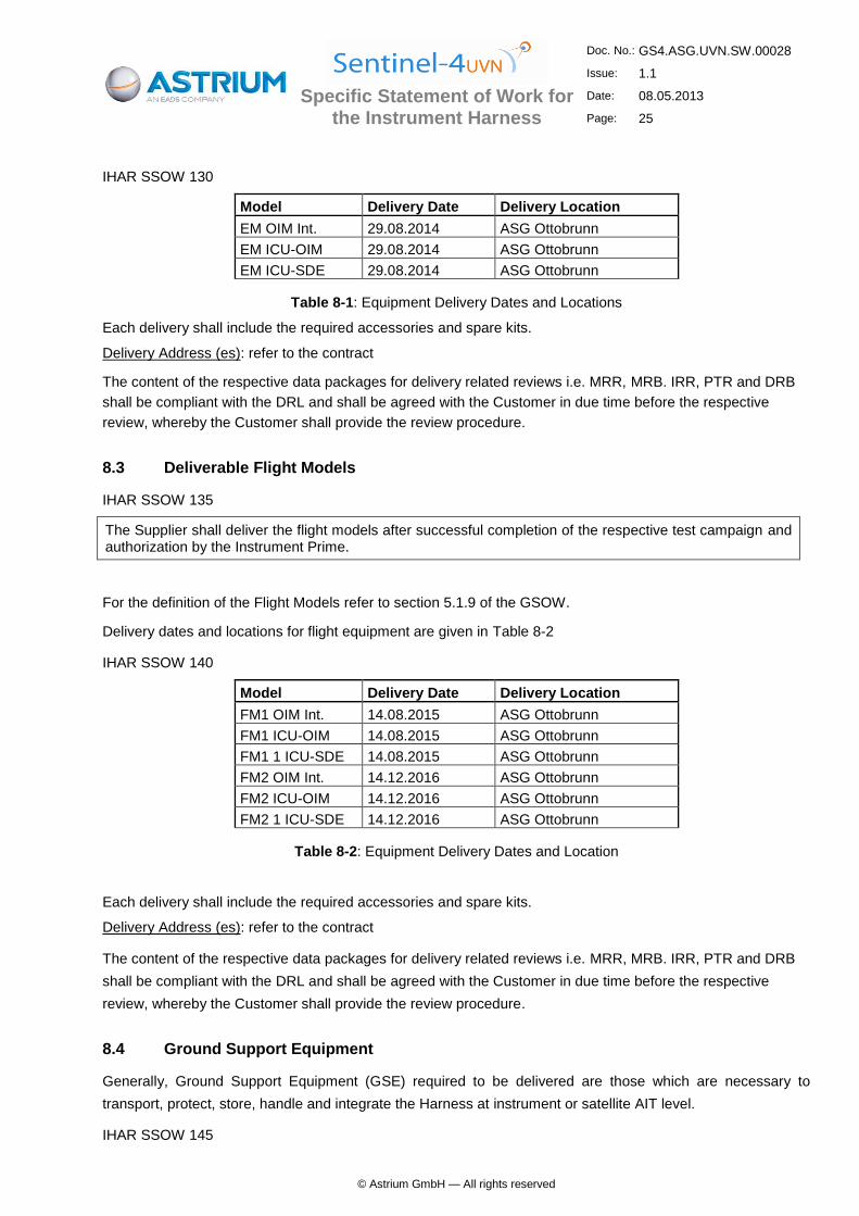
IHAR SSOW 130
Model Delivery Date Delivery Location
EM OIM Int. 29.08.2014 ASG Ottobrunn
EM ICU-OIM 29.08.2014 ASG Ottobrunn
EM ICU-SDE 29.08.2014 ASG Ottobrunn
Table 8-1: Equipment Delivery Dates and Locations
Each delivery shall include the required accessories and spare kits.
Delivery Address (es): refer to the contract
The content of the respective data packages for delivery related reviews i.e. MRR, MRB. IRR, PTR and DRB
shall be compliant with the DRL and shall be agreed with the Customer in due time before the respective
review, whereby the Customer shall provide the review procedure.
8.3 Deliverable Flight Models
IHAR SSOW 135
The Supplier shall deliver the flight models after successful completion of the respective test campaign and authorization by the Instrument Prime.
For the definition of the Flight Models refer to section 5.1.9 of the GSOW.
Delivery dates and locations for flight equipment are given in Table 8-2
IHAR SSOW 140
Model Delivery Date Delivery Location
FM1 OIM Int. 14.08.2015 ASG Ottobrunn
FM1 ICU-OIM 14.08.2015 ASG Ottobrunn
FM1 1 ICU-SDE 14.08.2015 ASG Ottobrunn
FM2 OIM Int. 14.12.2016 ASG Ottobrunn
FM2 ICU-OIM 14.12.2016 ASG Ottobrunn
FM2 1 ICU-SDE 14.12.2016 ASG Ottobrunn
Table 8-2: Equipment Delivery Dates and Location
Each delivery shall include the required accessories and spare kits.
Delivery Address (es): refer to the contract
The content of the respective data packages for delivery related reviews i.e. MRR, MRB. IRR, PTR and DRB
shall be compliant with the DRL and shall be agreed with the Customer in due time before the respective
review, whereby the Customer shall provide the review procedure.
8.4 Ground Support Equipment
Generally, Ground Support Equipment (GSE) required to be delivered are those which are necessary to
transport, protect, store, handle and integrate the Harness at instrument or satellite AIT level.
IHAR SSOW 145
Specific Statement of Work for the Instrument Harness
Doc. No.: GS4.ASG.UVN.SW.00028
Issue: 1.1
Date: 08.05.2013
Page: 26
© Astrium GmbH — All rights reserved
The Supplier shall ensure a safe delivery of the hardware items in appropriate reusable containers:
• internal OIM harness shall be baked-out, packed in sealed plastic bags and shipped in boxes
• external OIM internal MTG harness assembly shall be shipped to the AIT site mounted on its mockup
Technical requirements can be found in the instrument harness specification GS4.ASG.UVN.RS.00049_2.0 at
§11.2 "Mockup" and §15 "Package and Shipping Requirements".
IHAR SSOW 150
In case special harness transport containers are needed for transport between harness Supplier facilities and
AIT facilities the harness Supplier shall design and procure the subject container/s.
Proposal:
Supplier shall design and procure the boxes and containers for transportation between harness Supplier
facilities and AIT facilities.
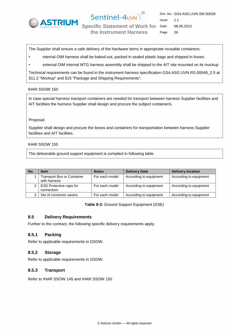
IHAR SSOW 155
The deliverable ground support equipment is compiled in following table.
No. Item Notes Delivery Date Delivery location
1 Transport Box or Container with harness.
For each model According to equipment According to equipment
2 ESD Protective caps for connectors
For each model According to equipment According to equipment
3 Set of connector savers For each model According to equipment According to equipment
Table 8-3: Ground Support Equipment (GSE)
8.5 Delivery Requirements
Further to the contract, the following specific delivery requirements apply.
8.5.1 Packing
Refer to applicable requirements in GSOW.
8.5.2 Storage
Refer to applicable requirements in GSOW.
8.5.3 Transport
Refer to IHAR SSOW 145 and IHAR SSOW 150

Specific Statement of Work for the Instrument Harness
Doc. No.: GS4.ASG.UVN.SW.00028
Issue: 1.1
Date: 08.05.2013
Page: 27
© Astrium GmbH — All rights reserved
8.6 Customer Undertakings
8.6.1 Customer Documents and Models
The Customer is committed to deliver the following inputs:
Item Remark
MICD EM + CAD Model OIM and MTG modules, harness stay-in/-out areas
and connector bracket locations.
EICD EM OIM + Electrical
Definition File
Connectivity Definition (connector list, pin-to-pin lists,
cable definition)
MICD FMs + CAD Model OIM and MTG modules, harness stay-in/-out areas
and connector bracket locations.
EICD FMs OIM + Electrical
Definition File
Connectivity Definition (connector list, pin-to-pin lists,
cable definition)
8.6.2 Other Customer Undertakings
The connectivity defined by the electrical ICDs listed in para. 8.6.1 will be provided on a computer media, in a
format to be agreed between the Supplier and the Customer.
8.7 Harness Integration
IHAR SSOW 160
The Supplier shall be responsible for test and integration of the IHAR parts according to the instrument
harness specification as well as for providing AIT support as follows:
Execute the integration and all related tests of the EM and FMs OIM internal harnesses onto the OIM at Customer site including grounding and bonding measurements after harness installation.
Execute the integration of the EM and FMs ICU-SDE and ICU-OIM harnesses on suited AIT mock-
up at Customer site and performance of the grounding and bonding measurements after harness
installation.
Assist in failure investigation.
Support to S4-UVN instrument and MTG satellite level AIT activities on time and material basis.
IHAR SSOW 165
As OPTION, the supplier shall provide a quotation for the following activities
Execute the mechanical integration of the Scanner Harness subassembly EM and FM OIM internal harnesses onto the OIM at Customer site and perform the grounding and bonding measurements after harness installation.
Execute the mechanical integration of the FSE/FEE harness subassembly (flex excluded) EM and FM OIM internal harnesses onto the OIM at Customer site and perform the grounding and bonding measurements after harness installation.

Specific Statement of Work for the Instrument Harness
Doc. No.: GS4.ASG.UVN.SW.00028
Issue: 1.1
Date: 08.05.2013
Page: 28
© Astrium GmbH — All rights reserved
IHAR SSOW 170
Thermal Hardware as Thermistors and Heatermats are not part of the harness. They are installed in the OIM with "flying leads", which shall be equipped with connectors and shielding by the harness Supplier.
IHAR SSOW 175
After harness integration on the satellite, the Subcontractor shall check the insulation and continuity of the harness and shall measure the resistance of the thermal harness.
IHAR SSOW 180
The Supplier shall define and provide all the procedures needed at system level for AIT activities: handling,
integration, maintaining, repairing and replacement.
IHAR SSOW 185
The Supplier shall be fully responsible for all necessary repairs resulting from design/manufacture defects,
random failures or other causes directly attributable to the Supplier.
8.8 Post Delivery Support
The post delivery activities start after completion of the IHAR integration onto the instrument or satellite by the
harness manufacturer.
IHAR SSOW 190
In order to assist failure investigations, repairings and changes during S4-UVN instrument and MTG satellite level AIT activities, the Supplier shall guarantee support on experienced project engineering personnel, qualified personnel in harness manufacturing at AIT sites, time and material basis.
IHAR SSOW 205
For the application of harness changes (e.g. connector pin allocation, additional line) the corresponding
repair procedures shall be provided by the harness Supplier.
---------------- END OF DOCUMENT ----------------