S206E057 -- Lecture 16, 5/22/2016, Rhino 3D, Grasshopper...
9
S206E057 – Spring 2016 Page 1 (5/1/2016) Copyright ©2016, Chiu-Shui Chan. All Rights Reserved. Create regular features on façade and form: Modeling panel features or structural components could be done by a few components found in LunchBox, which is a GH plug-in for exploring mathematical shapes, paneling, structures, and workflow. Particularly, the panel patterns on surfaces could be created (by the panel functions) to serve as divided surface systems. The latest release of LunchBox is built to fit Grasshopper 0.90014 and Rhino 5.0, which could be found on http://www.grasshopper3d.com/group/lunchbox. This plug- in includes the following tools, and detailed components are diagrammatically shown on the last page of this handout. 1. Generate: Components for cool generative geometry. 2. Math: Create parametric surfaces and forms such as the Mobius, Klein, or 3D Supershape 3. Panels: Create paneling systems such as quad grids, diamonds, or triangles. 4. Structure: Create wire structures such as diagrids or space trusses. 5. Utility: Rationalize spline curves and reverse surfaces. 6. Workflow: Read and write Excel files and automate baking and saving. Methods of installing LunchBox are the same as any plug-in installations. Here are the typical installation sequences, again, provided FYI. • Download the ZIP package. • In Grasshopper, choose File > Special Folders > Components folder. Save the LunchBox.gha file there. • Right-click the file > Properties > make sure there is no "blocked" text • Restart Rhino and Grasshopper, the LunchBox will appear as one of the tags in the tag area next to the Display tag. Example one: Applications of LunchBox: http://designreform.net/learning/2012/08/02/lunchbox-paneling-tools 1. In Rhino, use “Surface from a 3 or 4 corner points” tool to generate a surface on front view. This surface shall be an untrimmed free surface. 2. In GH, apply a Surface component > “Set One Surface” and assign the surface to it. 3. From the LunchBox tag, apply the “Staggered Quad Panel” to generate the brick pattern on the face. 4. Define integer number sliders for U and V, which defines the number of staggered faces along X and Y axes. 5. Define “Random Split List” component, link the panel from Quad Staggered to the list of the “Random Split List” to see the randomly split surfaces of A and B. R on the Random Split List controls the randomization of the split which is defined by a slider for the number of seed to generate variations. S controls how many panels go to either A or B (or the proportion of the randomness for A and B). 6. To see the results of random split of the faces visually, use two Surface components and link the output of A & B to these two Surface components. 7. Then, Offset one or two of the faces to see the panel (or the brick pattern on façade). See the image A below which has the offset faces without thickness. 8. To make a solid from each group of surfaces, use Box Rectangle with a number slider to control the height for making boxes. Here, each surface has its rectangle which was created by Quad Staggered component. See the image B below. S206E057 -- Lecture 16, 5/22/2016, Rhino 3D, Grasshopper & Architecture Modeling
Transcript of S206E057 -- Lecture 16, 5/22/2016, Rhino 3D, Grasshopper...

S206E057 – Spring 2016
Page 1 (5/1/2016)
Copyright ©2016, Chiu-Shui Chan. All Rights Reserved. Create regular features on façade and form: Modeling panel features or structural components could be done by a few components found in LunchBox, which is a GH plug-in for exploring mathematical shapes, paneling, structures, and workflow. Particularly, the panel patterns on surfaces could be created (by the panel functions) to serve as divided surface systems. The latest release of LunchBox is built to fit Grasshopper 0.90014 and Rhino 5.0, which could be found on http://www.grasshopper3d.com/group/lunchbox. This plug-in includes the following tools, and detailed components are diagrammatically shown on the last page of this handout.
1. Generate: Components for cool generative geometry. 2. Math: Create parametric surfaces and forms such as the Mobius, Klein, or 3D Supershape 3. Panels: Create paneling systems such as quad grids, diamonds, or triangles. 4. Structure: Create wire structures such as diagrids or space trusses. 5. Utility: Rationalize spline curves and reverse surfaces. 6. Workflow: Read and write Excel files and automate baking and saving.
Methods of installing LunchBox are the same as any plug-in installations. Here are the typical installation sequences, again, provided FYI.
• Download the ZIP package. • In Grasshopper, choose File > Special Folders > Components folder. Save the LunchBox.gha file there. • Right-click the file > Properties > make sure there is no "blocked" text • Restart Rhino and Grasshopper, the LunchBox will appear as one of the tags in the tag area next to the Display
tag. Example one: Applications of LunchBox: http://designreform.net/learning/2012/08/02/lunchbox-paneling-tools
1. In Rhino, use “Surface from a 3 or 4 corner points” tool to generate a surface on front view. This surface shall be an untrimmed free surface.
2. In GH, apply a Surface component > “Set One Surface” and assign the surface to it.
3. From the LunchBox tag, apply the “Staggered Quad Panel” to generate the brick pattern on the face.
4. Define integer number sliders for U and V, which defines the number of staggered faces along X and Y axes.
5. Define “Random Split List” component, link the panel from Quad Staggered to the list of the “Random Split List” to see the randomly split surfaces of A and B. R on the Random Split List controls the randomization of the split which is defined by a slider for the number of seed to generate variations. S controls how many panels go to either A or B (or the proportion of the randomness for A and B).
6. To see the results of random split of the faces visually, use two Surface components and link the output of A & B to
these two Surface components.
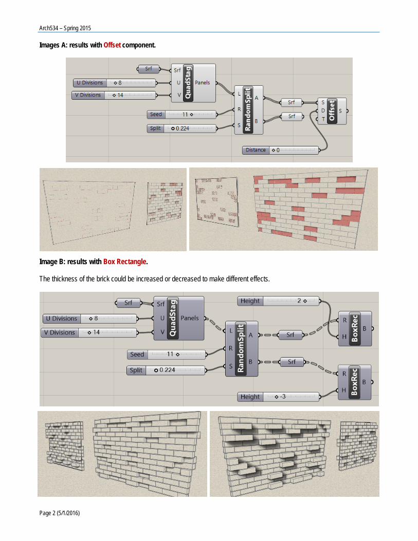
7. Then, Offset one or two of the faces to see the panel (or the brick pattern on façade). See the image A below which has the offset faces without thickness.
8. To make a solid from each group of surfaces, use Box Rectangle with a number slider to control the height for making boxes. Here, each surface has its rectangle which was created by Quad Staggered component. See the image B below.
S206E057 -- Lecture 16, 5/22/2016, Rhino 3D, Grasshopper & Architecture Modeling
Arch534 – Spring 2015
Page 2 (5/1/2016)
Images A: results with Offset component.
Image B: results with Box Rectangle. The thickness of the brick could be increased or decreased to make different effects.

S206E057 – Spring 2016
Page 3 (5/1/2016)
Irregular features on façade and backward thinking: For irregular shape creation, methods used are different. Here is the example of modeling an irregular façade in Rhino through GH.
1. Create the façade first with Surface Creation > Surface from 3 or 4 corner points function in the Front Viewport. This surface plane represents one of the facades.
2. Use Polyline to draw the irregular shape inside this surface.
3. Use split to take the irregular shape away from the surface. 4. Erase the irregular shape away. 5. ExtrudeCrv > Select the entire shape> In the sub-function area, turn the solid: Yes, Deletinput: Yes, Extrusion
distance: 3.
Following the methods of modeling in Rhino, the steps of executing the modeling could be converted into algorithms. Here are two versions of algorithms. Executing the backward thinking through GH (Version one): 1. The first algorithm is to apply Extrude Linear (Extrude) component to extrude the shape into 3D solid. The Extrude
Linear component needs the following four inputs.
• P is the profile curve or surface, which is the basic geometry. If it is curve input, then apply curves to construct the shape. If it is surface input, then apply surface tools to create the basic shape.
• Po indicates the orientation plane of the profile shape.
• A is the extrusion axis, which could be a drawn line represents the axis. • Ao is the orientation plane for the axis to rest on.
• Its output is a BREP representation of the geometry.

Arch534 – Spring 2015
Page 4 (5/1/2016)
2. In this Extrude (Linear) component, the profile could take either a curve or a surface input. In this example, the original
shape was created as a surface, so it is assigned to the Surface component for input. If it is a curve, then it might use Geometry as input format. (You could test if the BREP component could serve the input purpose.)
3. For the Po and Ao planes, it is defined and assigned as XZ Plane, because both objects of the Srf (surface) and Geo
(geometry) sit on the XZ planes and shall be extruded out from it. 4. For the extrusion Axis, it could be a drawn line representing the axis and is assigned to the geometry parameter for
serving the input for A component. The second version of backward thinking applied in GH (Version two): The geometry of the axis could be represented by a line component, which are defined by two points and controlled by six number sliders of x, y, z coordinates to make the change flexible. The 3D solid of the shape shall be created in either direction determined by positive or negative values. In this version two of the algorithm, the GH components applied for form generations are more completed and robust than version one. Question A: Could the final form created by the “Extrude Linear Component” be baked as Rhino model, saved as BREP geometry component and manipulated further? That relates to the notion of recursion which had been covered in lecture 11. An example is given in this handout. Question B: Could the entire creation of a building be implemented by GH? The answer is yes, but, it is not that efficient. Hybrid of Rhino and GH would be better. See the example below, which is the mixture of Rhino model and the GH components together with utilizing extra components provided by LunchBox plug-in.

S206E057 – Spring 2016
Page 5 (5/1/2016)
The LunchBox plug-in is able to do regular shape generation. For instance, the repetitive window openings in this example were done through “Quad Panels” component to create quadrangular panels on a surface in GH. There is a function of “Path Mapper”, which creates a data tree for the lexical data items. The way to change the lexical data format is executed by Lexer Combo Editor. Click on the icon to open the Lexer Editor. Inside the Editor, type {A;B;C;D} for the source and {A;B;C;D%2=0;D} for the target. The output of Path Mapper will be a part of the data tree input for Simplify Component.

Arch534 – Spring 2015
Page 6 (5/1/2016)

S206E057 – Spring 2016
Page 7 (5/1/2016)
Coding example:
Question: Could the final baked model be applied again through BREP and manipulated even further? This question relates to the concept of GH recursion versus form recursion, which could be found in the following example. Free form manipulation (or modification): This example is to create a cracked effect for a sculpture, which is shown on the following pictures. The sculpture has been modeled in Rhino as shown in the image on the right. This example is to apply a GH algorithm to create the special effects for the Rhino geometry, which could be converted into a Rhino model again. The algorithm is called “BREP Cracking” that could be found on “food4Rhino” Web site. However, it was written in Chinese and couldn’t find English translation. Here are the brief explanations of the algorithm applied and explained here for GH exercise reference.
1. The form is the geometry encoded in BREP parameter component in Grasshopper.
2. Through the HoopSnake iteration, edges of each cell are divided (or broken) 13 times to generate cracking effects along edges. HoopSnake is the recursive function. Its changing data (or Data input) was provided by the BREP Creaking component which was loaded from the Grasshopper User Group.

Arch534 – Spring 2015
Page 8 (5/1/2016)
3. The broken edges were joined through Join Curves component to make better results.
4. Finally, the entire form is defined as blue color through Color Swatch and displayed through Custom Preview to make a cyan color for the object.
5. The final form in Custom Preview could be baked into Rhino as a solid model. Here is the coding example of the cracking algorithm. Differences between the original image and the created final effects.

S206E057 – Spring 2016
Page 9 (5/1/2016)
Lists of the available LunchBox function components. This image of the LuncBox function components was adapted from the LunchBox web site and pasted here for the class information, http://www.grasshopper3d.com/group/lunchbox. Please take some time to explore their applications. Reminder: The due date of assignment #2 would be 3/29/2016.


![INTRODUCTION TO GRASSHOPPER - Amazon S3s3.amazonaws.com/mcneel/grasshopper/Grasshopper_Intro_Outline.pdf · Introduction to Grasshopper-[GH-01] INTRODUCTION TO GRASSHOPPER Block 5-Day](https://static.fdocuments.us/doc/165x107/5ada38217f8b9a137f8d3089/introduction-to-grasshopper-amazon-s3s3-to-grasshopper-gh-01-introduction-to.jpg)


![Introduction and Intermediate - Grasshopper-[GH-102]files.mcneel.com/grasshopper/GH_2_Day_7_Hours.pdf · Introduction and Intermediate - Grasshopper-[GH-102] Target Audience This](https://static.fdocuments.us/doc/165x107/5ee07629ad6a402d666ba3d5/introduction-and-intermediate-grasshopper-gh-102files-introduction-and-intermediate.jpg)