S1-552/2 5kV Digital Insulation Tester - · PDF fileThe S1-552/2 is a microprocessor...
24
M S1-552/2 5kV Digital Insulation Tester USER MANUAL
Transcript of S1-552/2 5kV Digital Insulation Tester - · PDF fileThe S1-552/2 is a microprocessor...
M
S1-552/25kV Digital Insulation Tester
USER MANUAL
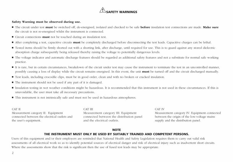
GSAFETY WARNINGS
Safety Warning must be observed during use.
n The circuit under test must be switched off, de-energised, isolated and checked to be safe before insulation test connections are made. Make sure
the circuit is not re-energised whilst the instrument is connected.
n Circuit connections must not be touched during an insulation test.
n After completing a test, capacitive circuits must be completely discharged before disconnecting the test leads. Capacitive charges can be lethal.
n Tested items should be firmly shorted out with a shorting link, after discharge, until required for use. This is to guard against any stored dielectric
absorption charge subsequently being released thereby raising the voltage to potentially dangerous levels.
n The voltage indicator and automatic discharge features should be regarded as additional safety features and not a substitute for normal safe working
practice.
n It is rare, but in certain circumstances, breakdown of the circuit under test may cause the instrument to terminate the test in an uncontrolled manner,
possibly causing a loss of display while the circuit remains energised. In this event, the unit must be turned off and the circuit discharged manually.
n Test leads, including crocodile clips, must be in good order, clean and with no broken or cracked insulation.
n The instrument should not be used if any part of it is damaged.
n Insulation testing in wet weather conditions might be hazardous. It is recommended that this instrument is not used in these circumstances. If this is
unavoidable, the user must take all necessary precautions.
n This instrument is not intrinsically safe and must not be used in hazardous atmospheres.
2
NOTETHE INSTRUMENT MUST ONLY BE USED BY SUITABLY TRAINED AND COMPETENT PERSONS.
Users of this equipment and/or their employers are reminded that National Health and Safety Legislation requires them to carry out valid risk
assessments of all electrical work so as to identify potential sources of electrical danger and risk of electrical injury such as inadvertent short circuits.
Where the assessments show that the risk is significant then the use of fused test leads may be appropriate.
CAT IIMeasurement category II: Equipment connected between the electrical outlets and the user’s equipment.
CAT IIIMeasurement category III: Equipment connected between the distribution panel and the electrical outlets.
CAT IV Measurement category IV: Equipment connected between the origin of the low-voltage mains supply and the distribution panel.
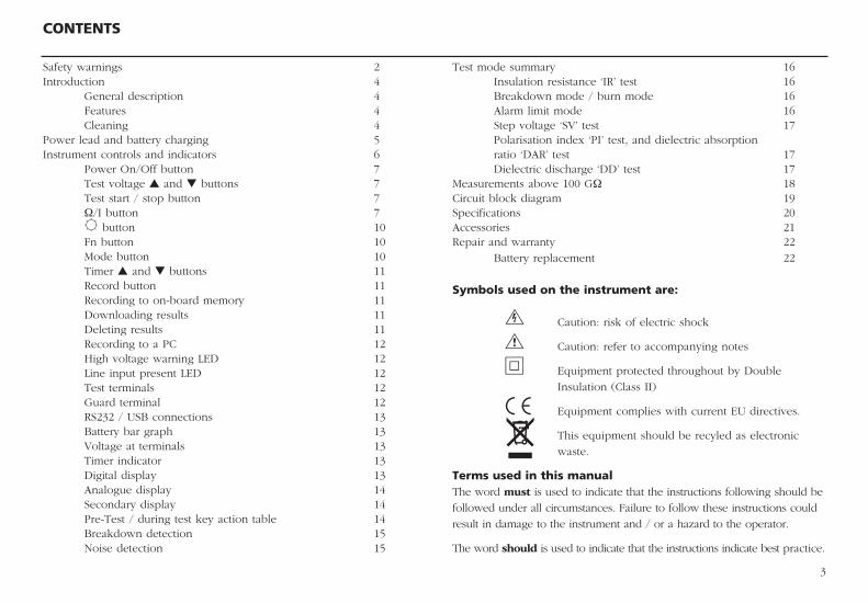
Test mode summary 16 Insulation resistance ‘IR’ test 16 Breakdown mode / burn mode 16 Alarm limit mode 16 Step voltage ‘SV’ test 17 Polarisation index ‘PI’ test, and dielectric absorption ratio ‘DAR’ test 17 Dielectric discharge ‘DD’ test 17Measurements above 100 GΩ 18Circuit block diagram 19Specifications 20Accessories 21Repair and warranty 22
Battery replacement 22
Symbols used on the instrument are:
F Caution: risk of electric shock
G Caution: refer to accompanying notes
t Equipment protected throughout by Double
Insulation (Class II)
c Equipment complies with current EU directives.
This equipment should be recyled as electronic
waste.
Terms used in this manual The word must is used to indicate that the instructions following should be
followed under all circumstances. Failure to follow these instructions could
result in damage to the instrument and / or a hazard to the operator.
The word should is used to indicate that the instructions indicate best practice.
CONTENTS
3
Safety warnings 2Introduction 4 General description 4 Features 4 Cleaning 4Power lead and battery charging 5Instrument controls and indicators 6 Power On/Off button 7 Test voltage s and t buttons 7 Test start / stop button 7 Ω/I button 7 B button 10 Fn button 10 Mode button 10 Timer s and t buttons 11 Record button 11 Recording to on-board memory 11 Downloading results 11 Deleting results 11 Recording to a PC 12 High voltage warning LED 12 Line input present LED 12 Test terminals 12 Guard terminal 12 RS232 / USB connections 13 Battery bar graph 13 Voltage at terminals 13 Timer indicator 13 Digital display 13 Analogue display 14 Secondary display 14 Pre-Test / during test key action table 14 Breakdown detection 15 Noise detection 15
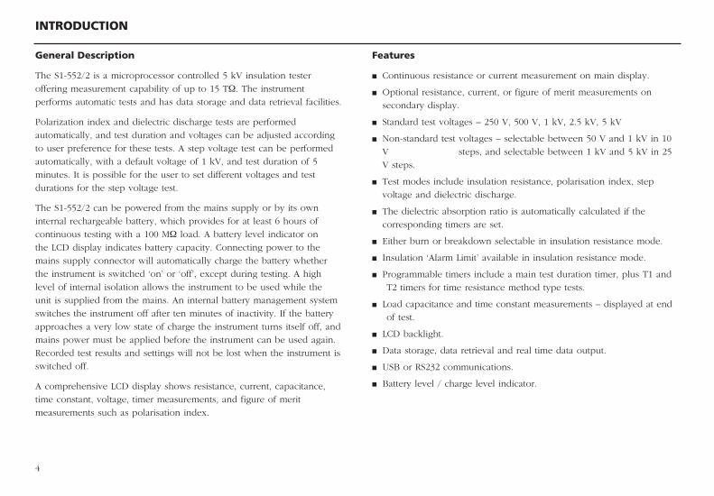
Features
n Continuous resistance or current measurement on main display.
n Optional resistance, current, or figure of merit measurements on
secondary display.
n Standard test voltages – 250 V, 500 V, 1 kV, 2.5 kV, 5 kV
n Non-standard test voltages – selectable between 50 V and 1 kV in 10
V steps, and selectable between 1 kV and 5 kV in 25
V steps.
n Test modes include insulation resistance, polarisation index, step
voltage and dielectric discharge.
n The dielectric absorption ratio is automatically calculated if the
corresponding timers are set.
n Either burn or breakdown selectable in insulation resistance mode.
n Insulation ‘Alarm Limit’ available in insulation resistance mode.
n Programmable timers include a main test duration timer, plus T1 and
T2 timers for time resistance method type tests.
n Load capacitance and time constant measurements – displayed at end
of test.
n LCD backlight.
n Data storage, data retrieval and real time data output.
n USB or RS232 communications.
n Battery level / charge level indicator.
INTRODUCTION
4
General Description
The S1-552/2 is a microprocessor controlled 5 kV insulation tester
offering measurement capability of up to 15 TΩ. The instrument
performs automatic tests and has data storage and data retrieval facilities.
Polarization index and dielectric discharge tests are performed
automatically, and test duration and voltages can be adjusted according
to user preference for these tests. A step voltage test can be performed
automatically, with a default voltage of 1 kV, and test duration of 5
minutes. It is possible for the user to set different voltages and test
durations for the step voltage test.
The S1-552/2 can be powered from the mains supply or by its own
internal rechargeable battery, which provides for at least 6 hours of
continuous testing with a 100 MΩ load. A battery level indicator on
the LCD display indicates battery capacity. Connecting power to the
mains supply connector will automatically charge the battery whether
the instrument is switched ‘on’ or ‘off’, except during testing. A high
level of internal isolation allows the instrument to be used while the
unit is supplied from the mains. An internal battery management system
switches the instrument off after ten minutes of inactivity. If the battery
approaches a very low state of charge the instrument turns itself off, and
mains power must be applied before the instrument can be used again.
Recorded test results and settings will not be lost when the instrument is
switched off.
A comprehensive LCD display shows resistance, current, capacitance,
time constant, voltage, timer measurements, and figure of merit
measurements such as polarisation index.
POWER LEAD AND BATTERY CHARGING
5
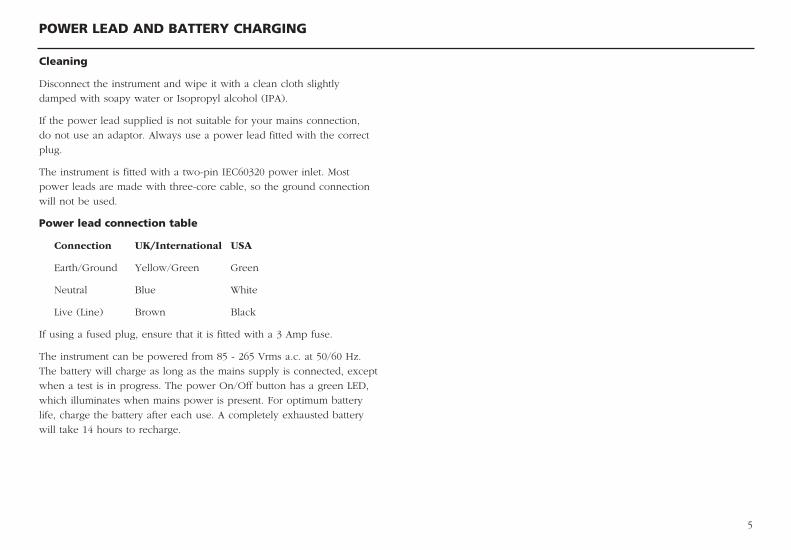
Cleaning
Disconnect the instrument and wipe it with a clean cloth slightly
damped with soapy water or Isopropyl alcohol (IPA).
If the power lead supplied is not suitable for your mains connection,
do not use an adaptor. Always use a power lead fitted with the correct
plug.
The instrument is fitted with a two-pin IEC60320 power inlet. Most
power leads are made with three-core cable, so the ground connection
will not be used.
Power lead connection table
Connection UK/International USA
Earth/Ground Yellow/Green Green
Neutral Blue White
Live (Line) Brown Black
If using a fused plug, ensure that it is fitted with a 3 Amp fuse.
The instrument can be powered from 85 - 265 Vrms a.c. at 50/60 Hz.
The battery will charge as long as the mains supply is connected, except
when a test is in progress. The power On/Off button has a green LED,
which illuminates when mains power is present. For optimum battery
life, charge the battery after each use. A completely exhausted battery
will take 14 hours to recharge.
INSTRUMENT CONTROLS AND INDICATORS
6
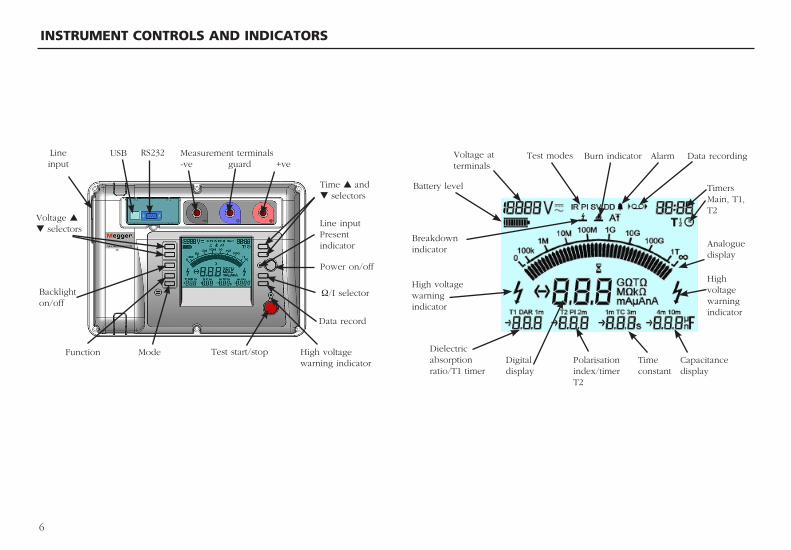
Measurement terminals-ve guard +ve
RS232USBLine input
Time s and t selectors
Voltage s
t selectorsLine input Present indicator
Power on/off
Ω/I selector
Burn indicator Alarm Data recordingTest modesVoltage at terminals
Battery level
Breakdown indicator
High voltage warning indicator
High voltage warning indicator
Analogue display
TimersMain, T1, T2
Dielectric absorption ratio/T1 timer
Digitaldisplay
Polarisation index/timer T2
Time constant
Capacitance display
Data record
High voltage warning indicator
Test start/stopModeFunction
Backlighton/off
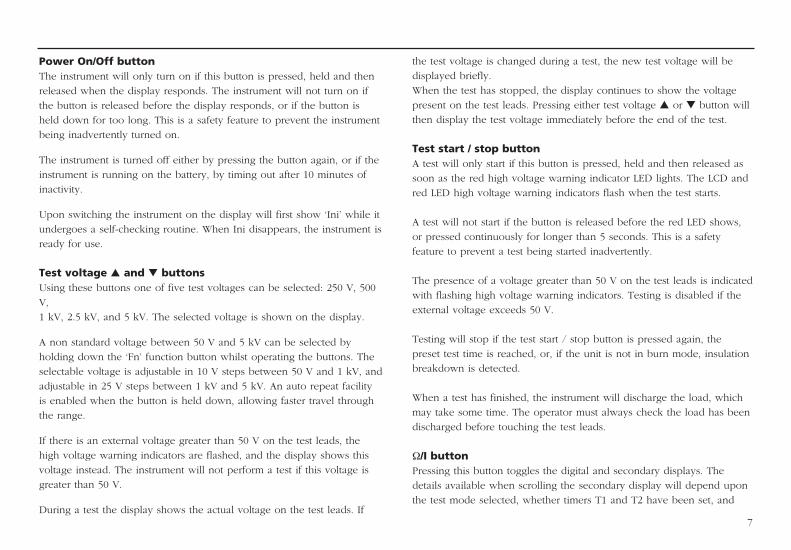
7
the test voltage is changed during a test, the new test voltage will be
displayed briefly.
When the test has stopped, the display continues to show the voltage
present on the test leads. Pressing either test voltage s or t button will
then display the test voltage immediately before the end of the test.
Test start / stop buttonA test will only start if this button is pressed, held and then released as
soon as the red high voltage warning indicator LED lights. The LCD and
red LED high voltage warning indicators flash when the test starts.
A test will not start if the button is released before the red LED shows,
or pressed continuously for longer than 5 seconds. This is a safety
feature to prevent a test being started inadvertently.
The presence of a voltage greater than 50 V on the test leads is indicated
with flashing high voltage warning indicators. Testing is disabled if the
external voltage exceeds 50 V.
Testing will stop if the test start / stop button is pressed again, the
preset test time is reached, or, if the unit is not in burn mode, insulation
breakdown is detected.
When a test has finished, the instrument will discharge the load, which
may take some time. The operator must always check the load has been
discharged before touching the test leads.
Ω/I buttonPressing this button toggles the digital and secondary displays. The
details available when scrolling the secondary display will depend upon
the test mode selected, whether timers T1 and T2 have been set, and
Power On/Off buttonThe instrument will only turn on if this button is pressed, held and then
released when the display responds. The instrument will not turn on if
the button is released before the display responds, or if the button is
held down for too long. This is a safety feature to prevent the instrument
being inadvertently turned on.
The instrument is turned off either by pressing the button again, or if the
instrument is running on the battery, by timing out after 10 minutes of
inactivity.
Upon switching the instrument on the display will first show ‘Ini’ while it
undergoes a self-checking routine. When Ini disappears, the instrument is
ready for use.
Test voltage s and t buttonsUsing these buttons one of five test voltages can be selected: 250 V, 500
V,
1 kV, 2.5 kV, and 5 kV. The selected voltage is shown on the display.
A non standard voltage between 50 V and 5 kV can be selected by
holding down the ‘Fn’ function button whilst operating the buttons. The
selectable voltage is adjustable in 10 V steps between 50 V and 1 kV, and
adjustable in 25 V steps between 1 kV and 5 kV. An auto repeat facility
is enabled when the button is held down, allowing faster travel through
the range.
If there is an external voltage greater than 50 V on the test leads, the
high voltage warning indicators are flashed, and the display shows this
voltage instead. The instrument will not perform a test if this voltage is
greater than 50 V.
During a test the display shows the actual voltage on the test leads. If
8
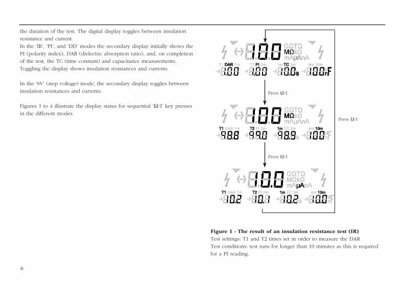
Figure 1 - The result of an insulation resistance test (IR)Test settings: T1 and T2 times set in order to measure the DAR
Test conditions: test runs for longer than 10 minutes as this is required
for a PI reading.
the duration of the test. The digital display toggles between insulation
resistance and current.
In the ‘IR’, ‘PI’, and ‘DD’ modes the secondary display initially shows the
PI (polarity index), DAR (dielectric absorption ratio), and, on completion
of the test, the TC (time constant) and capacitance measurements.
Toggling the display shows insulation resistances and currents.
In the ‘SV’ (step voltage) mode, the secondary display toggles between
insulation resistances and currents.
Figures 1 to 4 illustrate the display status for sequential ‘Ω/I’ key presses
in the different modes.
Press Ω/I
Press Ω/I
Press Ω/I
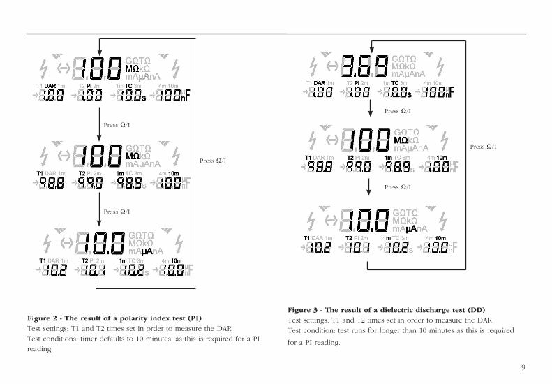
Figure 2 - The result of a polarity index test (PI)Test settings: T1 and T2 times set in order to measure the DAR
Test conditions: timer defaults to 10 minutes, as this is required for a PI
reading
Figure 3 - The result of a dielectric discharge test (DD)Test settings: T1 and T2 times set in order to measure the DAR
Test condition: test runs for longer than 10 minutes as this is required
for a PI reading.
Press Ω/I
Press Ω/I
Press Ω/I
9
Press Ω/I
Press Ω/I
Press Ω/I
10
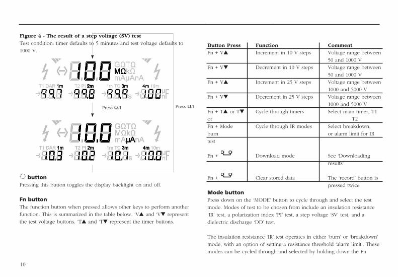
Button Press Function CommentFn + Vs Increment in 10 V steps Voltage range between
50 and 1000 V
Fn + Vt Decrement in 10 V steps Voltage range between
50 and 1000 V
Fn + Vs Increment in 25 V steps Voltage range between
1000 and 5000 V
Fn + Vt Decrement in 25 V steps Voltage range between
1000 and 5000 V
Fn + Ts or Tt Cycle through timers Select main timer, T1
or T2
Fn + Mode Cycle through IR modes Select breakdown,
burn or alarm limit for IR
test
Fn + Download mode See ‘Downloading
results’
Fn + Clear stored data The ‘record’ button is
pressed twice
Mode buttonPress down on the ‘MODE’ button to cycle through and select the test
mode. Modes of test to be chosen from include an insulation resistance
‘IR’ test, a polarization index ‘PI’ test, a step voltage ‘SV’ test, and a
dielectric discharge ‘DD’ test.
The insulation resistance ‘IR’ test operates in either ‘burn’ or ‘breakdown’
mode, with an option of setting a resistance threshold ‘alarm limit’. These
modes can be cycled through and selected by holding down the Fn
B buttonPressing this button toggles the display backlight on and off.
Fn buttonThe function button when pressed allows other keys to perform another
function. This is summarized in the table below. ‘Vs and ‘Vt represent
the test voltage buttons. ‘Ts and ‘Tt represent the timer buttons.
Press Ω/I Press Ω/I
Figure 4 - The result of a step voltage (SV) testTest condition: timer defaults to 5 minutes and test voltage defaults to
1000 V.
11
Recording to on-board memoryPress the record button to start and stop recording. When data recording
is enabled the record symbol will flash on and off repeatedly. Recording
can only be activated before testing commences. Results are stored at
15, 30, 45 and 60 seconds. After 60 seconds, at minute intervals up to
10 minutes. After 10 minutes, results are recorded at 5 minute intervals
until the test terminates. At each interval the recorded data will contain
selected voltage, test time elapsed, voltage applied, leakage current, and
insulation resistance.
Downloading resultsConnect the instrument to the RS232 / USB port of a PC running
Download Manager. Refer to section ‘RS232 / USB connection’ for set up
details. Start Download Manager on your PC, select the S1-552 driver and
right click the icon. Select ‘Download’.
Switch the instrument on and wait until initialisation is complete. Press
the function key along with the record key. The instrument now displays
‘dld’ to indicate download mode. Press and hold down test button until
download begins, shown by analogue display lighting clockwise.
Results will not be erased during this operation and so may be
downloaded repeatedly.
Deleting test resultsSwitch the instrument on and wait until initialisation is complete. Hold
down the function key and press the record key twice. The instrument
now displays ‘clr’ to indicate clear mode. Press and hold down test
button until clear process begins, shown by analogue display lighting anti
clockwise. Press the MODE button to exit without deleting the results.
button and pressing the Mode button.
Timer s and t buttonsThe main timer can be set up to 99mins 59secs. The Ts button
increments the time, and the Tt button decrements the time in ten
seconds steps. An auto repeat facility allows the time to be set more
quickly. Setting a time of 00:00 disables the timer. With the timer
disabled a test has to be manually stopped.
The minimum timer setting is 15 seconds for test voltages of 1000 V or
more, and 30 seconds below this.
To select timer Tmain, T1 or T2, hold down the Fn button whilst
repeatedly pressing the Ts or Ttbuttons. To set the selected timer,
release the Fn button, and the use the Ts or Ttbuttons.
Note: T2 cannot exceed the time on main timer unless it is disabled
(00:00). T1 cannot exceed the time on T2.
Record buttonThis button is used to start and stop recording. Recording can only be
activated before testing. When data recording is enabled the ‘record’
symbol flashes.
Data is stored in solid-state memory and under normal circumstances
will maintain its integrity for in excess of ten years, but may rarely be
corrupted or lost by external influences such as transients and static
discharge. Megger Limited cannot accept responsibility for any losses of
data. Regular downloading to a PC using software such as Download
Manager will substantially reduce any such risk.
12
Recording to a PCWhile carrying out a test, the instrument will output the test voltage,
test current and resistance every second. Refer to section ‘RS232 / USB
connection’ for setup details. Connect the instrument to the RS232 / USB
port of the PC. The data may be captured with Microsoft® HyperTerminal
or another suitable programme.
High voltage warning LEDThis is a red LED next to the TEST button on the front panel. The LED
flashes when the voltage on the test inputs exceeds 50 V.
Line input present LEDThis is a green LED next to the power On/Off button on the front panel.
It is illuminated whenever the mains power is connected.
Test terminalsThere are three test terminals marked +, - and G. These terminals are
designed to accept only the test leads supplied. Shutters across the
terminals prevent accidental ingress of dirt and other objects. Test lead
plugs interlock with the shutters and are released by rotating the test lead
plug a quarter turn.
The Guard terminal is explained below and is only used in cases where
surface leakage currents need to be eliminated. Most measurements use
just the + and – terminals. The instrument’s internal voltage generator
drives the + terminal with respect to the – terminal, current being
measured in the – terminal.
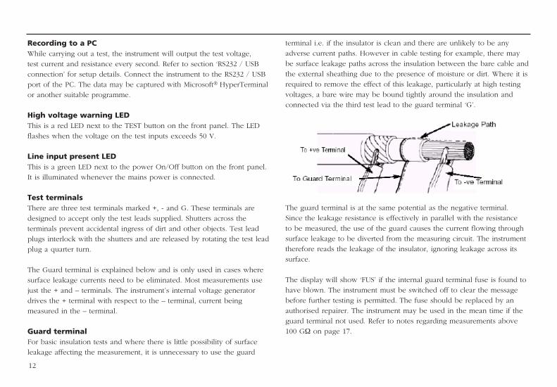
Guard terminalFor basic insulation tests and where there is little possibility of surface
leakage affecting the measurement, it is unnecessary to use the guard
terminal i.e. if the insulator is clean and there are unlikely to be any
adverse current paths. However in cable testing for example, there may
be surface leakage paths across the insulation between the bare cable and
the external sheathing due to the presence of moisture or dirt. Where it is
required to remove the effect of this leakage, particularly at high testing
voltages, a bare wire may be bound tightly around the insulation and
connected via the third test lead to the guard terminal ‘G’.
The guard terminal is at the same potential as the negative terminal.
Since the leakage resistance is effectively in parallel with the resistance
to be measured, the use of the guard causes the current flowing through
surface leakage to be diverted from the measuring circuit. The instrument
therefore reads the leakage of the insulator, ignoring leakage across its
surface.
The display will show ‘FUS’ if the internal guard terminal fuse is found to
have blown. The instrument must be switched off to clear the message
before further testing is permitted. The fuse should be replaced by an
authorised repairer. The instrument may be used in the mean time if the
guard terminal not used. Refer to notes regarding measurements above
100 GΩ on page 17.
13
RS232 / USB connectionData can be transferred to a PC via an RS232 or USB port. If using the
RS232 port, use the null modem cable supplied. The RS232 settings
are 38400 Baud, 8 data bits, 0 parity, 1 stop bit, no flow control
(handshake).
If using the USB port, ensure that the USB driver supplied on the
accompanying product CD has been installed BEFORE connecting the
instrument. Installation instructions are also to be found on the CD.
Programmes such as Megger Download Manager may be used to
download the results stored in memory. Programmes such as Microsoft®
HyperTerminal may be used to record real time data.
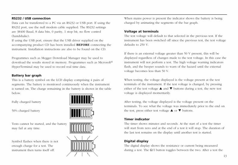
Battery bar graphThis is a battery symbol on the LCD display comprising 4 pairs of
segments. The battery is monitored continuously when the instrument
is turned on. The charge remaining in the battery is shown in the table
below.
Fully charged battery
50% charged battery
Tests cannot be started, and the battery
may fail at any time.
Symbol flashes when there is not
enough charge for a test. The
instrument then turns itself off.
When mains power is present the indicator shows the battery is being
charged by animating the segments of the bar graph.
Voltage at terminalsThe test voltage will default to that selected in the previous test. If the
instrument has been switched off since the previous test, the test voltage
defaults to 250 V.
If there is an external voltage greater than 50 V present, this will be
displayed regardless of changes made to the test voltage. In this case the
instrument will not perform a test. The high voltage warning indicators
flash, and the beeper sounds to warn of the hazard until the external
voltage becomes less than 50 V.
When testing, the voltage displayed is the voltage present at the test
terminals of the instrument. If the test voltage is changed, by pressing
either of the test voltage s and t buttons during a test, the new test
voltage is displayed momentarily.
After testing, the voltage displayed is the voltage present on the
terminals. To see what the voltage was immediately prior to the end on
the test, press either test voltage s or t buttons.
Timer indicatorThe timer shows minutes and seconds. At the start of a test the timer
will start from zero and at the end of a test it will stop. The duration of
the last test remains on the display until another test is started.
Digital displayThe digital display shows the resistance or current being measured
during a test. The Ω/I button toggles between the two. After a test the
14
display shows the last measurement made until the timer or voltage test
settings are changed or the test start/stop button is pressed.
Analogue displayThis simulates an analogue meter movement to give the user a better
“feel” for how a measurement is progressing. The analogue display
shows resistance only.
The display is also used to indicate how ‘result download’ and ‘deletion
of results’ is progressing.
Secondary displayThis part of the display shows the results of ‘time resistance’ method
tests.
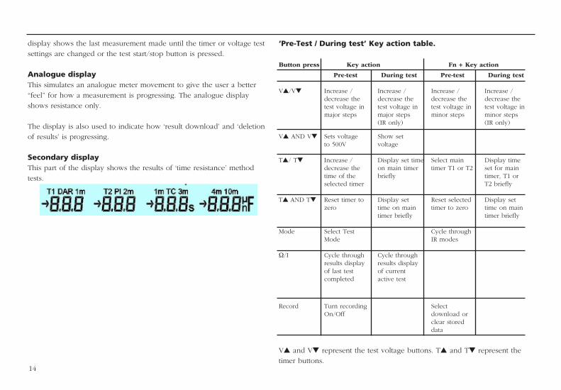
‘Pre-Test / During test’ Key action table.
Button press Key action Fn + Key action
Pre-test During test Pre-test During test
Vs/Vt Increase / Increase / Increase / Increase / decrease the decrease the decrease the decrease the test voltage in test voltage in test voltage in test voltage in major steps major steps minor steps minor steps (IR only) (IR only)
Vs AND Vt Sets voltage Show set to 500V voltage
Ts/ Tt Increase / Display set time Select main Display time decrease the on main timer timer T1 or T2 set for main time of the briefly timer, T1 or selected timer T2 briefly
Ts AND Tt Reset timer to Display set Reset selected Display set zero time on main timer to zero time on main timer briefly timer briefly
Mode Select Test Cycle through Mode IR modes
Ω/I Cycle through Cycle through results display results display of last test of current completed active test
Record Turn recording Select On/Off download or clear stored data
Vs and Vt represent the test voltage buttons. Ts and Tt represent the
timer buttons.
15
On screen warning codes
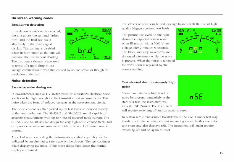
Breakdown detection
If insulation breakdown is detected,
the unit aborts the test and flashes
“brd” and the final test result
alternately in the main digital
display. This display is disabled
when in burn mode as the unit will
continue the test without aborting.
The instrument detects breakdown
in terms of a rapid drop in test
voltage commensurate with that caused by an arc across or though the
insulation under test.
Noise detection
Excessive noise during test
In environments such as HV switch yards or substations electrical noise
levels can be high enough to effect insulation test measurements. This
noise takes the form of induced currents in the measurement circuit.
The noise current is either picked up by test leads or induced directly
in the item under test. The S1-552/2 and S1-1052/2 are all capable of
accurate measurements with up to 3 mA of induced noise current. The
S1-554/2 and S1-1054/4 are design for very high noise environments and
can provide accurate measurements with up to 4 mA of noise current
present.
A level of noise exceeding the instruments specified capability will be
indicated by an alternating sine wave on the display. The test continues
while displaying the noise. If the noise drops back down the normal
display is resumed.
The effects of noise can be reduces significantly with the use of high
quality Megger screened test leads.
The picture displayed on the right
shows the expected screen result
of an IR test on with a 5000 V test
voltage after 2 minutes 9 seconds.
The black and grey waveforms are
displayed alternately while the noise
is present. When the noise is removed
the wave form is replaced by the
correct reading.
Test aborted due to extremely high noise
Should an extremely high level of
noise be present, particularly at the
start of a test, the instrument will
indicate nSE (Noise). The instrument
will require switching off and on again to reset.
In certain rare circumstances breakdown of the circuit under test may
interfere with the sensitive current measuring circuit. In this event the
unit stops and also displays nSE. The instrument will again require
switching off and on again to reset.
Press the ‘MODE’ button to cycle through and select the test mode.
Modes of test to be chosen from include an insulation resistance
‘IR’ test, a polarization index ‘PI’ test, a step voltage ‘SV’ test, and a
dielectric discharge ‘DD’ test. If timers T1 and T2 are set, the instrument
will automatically calculate the dielectric absorption ratio ‘DAR’ of the
insulation. PI, DAR, and IR values are automatically stored and displayed
if the data is available, irrespective of the selected test mode. At the end
of a test the instrument can be made to display either the insulation
resistances, insulation currents or ratios plus capacitance measurements
by using the ‘Ω/I’ toggle button. See section ‘Ω/I button’ for cycling
through results and toggling units.
Insulation Resistance ‘IR’ testThis is the default mode in which the instrument powers up. This
test mode measures insulation resistance continuously at the selected
voltage. The test voltage may be varied during an ‘IR’ test by pressing
the test voltage s or t buttons. The test duration can be set using the
‘main timer’. The test will finish automatically after this time has elapsed.
On test completion, insulation capacitance and the time constant
associated with it is calculated and displayed.
Time Constant (TC) = Rins x Cins
If timers T1 and T2 are set, the instrument will calculate and display
the DAR value under the segment ‘DAR’. On completion of the test,
the instrument will display the insulation resistance measured at these
times under the segment symbols ‘T1’ and ‘T2’. If the test runs for longer
than 10 minutes, the instrument will calculate the ‘polarisation index’.
This value will be displayed under the display segment symbol ‘PI’.
On completion of the test, the instrument will display the insulation
resistance recorded at 1 minute and 10 minutes under the segment
symbols ‘1m’ and ‘10m’.
16
TEST MODE SUMMARY
Pressing the ‘Ω/I’ button toggles the display to show the insulation
resistances, insulation currents, DAR and PI ratios, and capacitance. The
resistances and currents will be displayed under the ‘T1’, ‘T2’, ‘1m’ and
‘10m’ segment headings, the ratios under the ‘DAR’ and ‘PI’ segment
headings. The capacitance reading is indicated by its units of either ‘nF’
or ‘µF’. Refer to section ‘Ω/I button’.
Breakdown mode / burn modeThe insulation resistance ‘IR’ test operates in either the ‘Burn’ or
‘Breakdown’ mode of operation. The default mode is breakdown. To
change mode press and hold the function button, then press and release
the mode button repeatedly until the desired mode is indicated by the
flashing symbol on the display. Release the function button to select it.
In the breakdown mode the ‘Breakdown Indicator’ will be illuminated –
refer to page 6. In this mode the test will automatically terminate should
the insulation break down to prevent damage to the insulation under
test.
In the burn mode the ‘Burn Indicator’ is illuminated – refer page 6.
The burn mode disables the normal breakdown detection and enables
the insulation test voltage to continue even after breakdown of the
insulation. This will enable the location of the failure to be seen and
heard. Due to the potential damage that could occur, the unit produces
two long beeps when starting a test with burn mode activated.
Alarm limit modeThe insulation resistance ‘IR’ test has an option of setting an alarm limit. If
this mode is selected, the instrument will beep should the resistance reading
exceed a user selectable threshold. To set the limit, hold down the function
button, then press and release the mode button repeatedly until
minute period. Readings for contaminated insulation are fairly constant
because any absorption effects are masked by high leakage currents.
On completion of the test the polarisation index is displayed under the
segment heading ‘PI’.
Polarisation Index (PI) = R10 min
R1 min
The ‘Dielectric Absorption Ratio’ is the term applied to the polarisation
index using other time intervals set by T1 and T2.
If timers T1 and T2 are both set, then the insulation resistance measured
at these times is also recorded. These are displayed together with
the calculated dielectric absorption ratio under the T1, T2, and DAR
segments respectively.
The instrument can be made to display either the insulation resistances,
insulation currents or ratios plus capacitance measurements by using the
Ω/I toggle button. See section ‘Ω/I button’ for cycling through results
and toggling units.
Dielectric Absorption Ratio (DAR) = RT2 min
RT1 min
Dielectric discharge ‘DD’ testThe ‘DD’ test is a diagnostic insulation test that allows ageing,
deterioration, and voids in the insulation to be assessed. The result is
dependent on the discharge characteristic, so the internal condition
of the insulation is tested, largely independent of any surface
contamination. On discharge the capacitive component of the discharge
current decays from a high value with a relatively short time constant of
17
the ‘A ’ symbol is flashing on the display. Use the timer s and t
buttons to set the resistance threshold between the limits of 10 kΩ and
15 TΩ. Release the function button to save the current limit. Adjusting
the alarm threshold level automatically activates the alarm limit mode.
This is indicated by the ‘A ’ symbol turning solidly on.
To toggle the alarm limit mode on/off, hold down the function button,
then press and release the mode button repeatedly until the ‘A ’ symbol
is flashing on the display. Release the function key to toggle.
Step voltage ‘SV’ testThis is a test based on the principle that an ideal insulator will produce
identical readings at all voltages, while an insulator which is being over
stressed, will show lower insulation values at higher voltages. The main
timer and test voltage settings can be adjusted if desired from their
default values of 5 minutes and 1 kV respectively. During the test the
applied test voltage incrementally steps by one fifth of the test voltage
setting (final value) every minute, for 5 minutes, taking successive
measurements until the final voltage is reached. Readings for the first 4
recorded values are displayed under the consecutive segment headings
‘1m’ to ‘4m’. The 5 minute reading is displayed by the main display.
If the range of measured insulation between readings is too wide for the
instrument to display, then those readings too small compared to the
final reading will be represented by ‘---’.
Polarisation index ‘PI’ test, and dielectric absorption ratio ‘DAR’ testThe ‘PI’ test is a particular example of a time/resistance method, which
takes the ratio of the insulation measured at 1 minute and at 10 minutes.
Good insulation generally shows an increase in resistance over a 10
a few seconds. The other current component, comprising the released
absorption current, decays from a lower value with a relatively long time
constant of up to several minutes. If this component of the discharge
current is large (>7 @ 500 V test voltage) then the insulation condition is
poor.
The main timer will default to 30 minutes, which is normally sufficient
time for full absorption to take place in an insulation material. The
default test voltage is set to 500 V. The ‘DD’ test requires the instrument
to measure the discharge current 1 minute after the removal of the
test voltage. At this time the capacitive current should be insignificant
compared with the released absorption current. On completion of the
test, the instrument uses this measurement along with the test voltage
and calculated capacitance to produce a figure of merit indicating the
quality of the insulation.
Dielectric Discharge (DD) = I1 min
V x C
where I is the measured current expressed in milliamps (mA), V is the
test voltage in Volts (V), and C is the measured capacitance in Farads
(F).
18
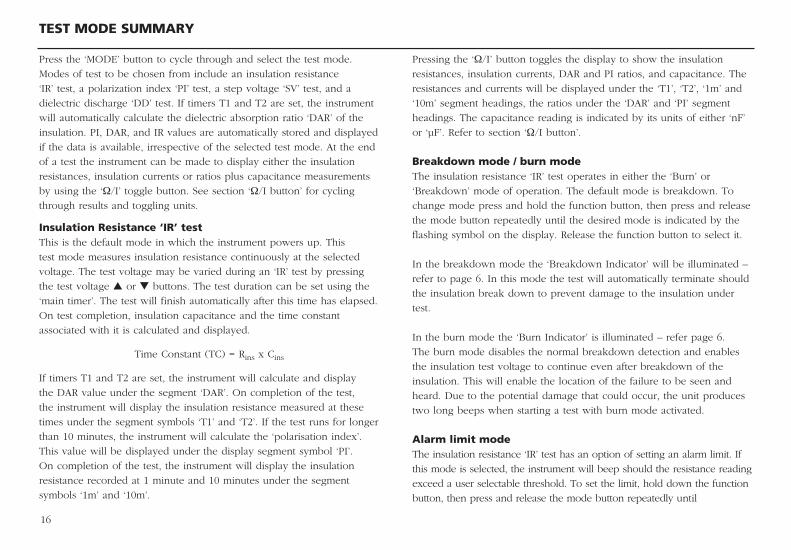
Measurements above 100 GΩ Measurements up to 100 GΩ can be made without any special
precautions, assuming that the test leads are reasonably clean and dry.
The guard lead can be used to remove the effects of surface leakage
if necessary. When measuring resistances above 100 GΩ, the test leads
should not be allowed to touch each other, or any other object since this
will introduce leakage paths. Sharp points at the test lead connections
should also be avoided since this will encourage corona discharge.
The output is isolated, and so will float relative to ground such that
the positive terminal is at plus half of the test voltage, and the negative
terminal is at minus half of the test voltage with respect to ground.
Leakages therefore occur between the positive terminal and ground,
between the negative terminal and ground, and directly between the
positive and negative terminals. These leakages have a significant effect
and can occur through the air itself.
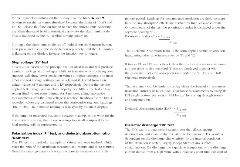
If the guard lead is connected to ground, then since the negative
terminal is at the same voltage as the guard terminal, the leakage into
the negative terminal will be considerably reduced. This will improve
accuracy because the current flowing into the negative terminal is
measured by the instrument and used to calculate resistance. This
technique is only permissible if the item under test is isolated from
ground. “Isolated” in this context means insulated by a resistance of at
+ Test V
2 - Test V
2
Ground
+ -
19
least 5 MΩ for the positive terminal, or at least 10 kΩ for the negative
terminal.
Conversely, if the positive terminal is grounded, then the negative
terminal will be at a voltage equal to the test voltage relative to ground,
which will result in an increase in leakage current, and worsening of
measurement accuracy.
When making measurements above 100 GΩ therefore, the user should
ground the Guard Lead where possible, otherwise parallel leakage paths
may occur.
Alternatively, screened leads are available as an optional accessory from
Megger. The lead to the negative terminal is fully screened. The screen
is plugged into the Guard terminal, diverting any stray leakage currents.
This considerably improves measurements made with a floating output,
where the leads might touch each other or anything other than the test
piece.
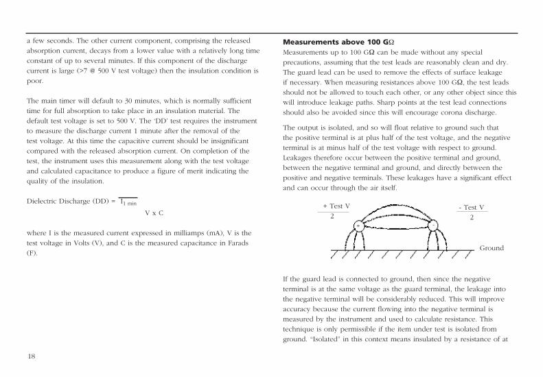
Circuit block diagram
For 5 kV instruments C1 = 47 nF, R1 = 50 kΩ, R2 = 40 kΩ
For 10 kV instruments C1 = 15 nF, R1 = 156 kΩ, R2 = 110 kΩ
+ Test V
0V
Ground
Guard+ -
100 MΩ
R1 R2
C1
Volts
Fuse
Cableunder test
+
-
G
Dischargeresistance
Current
Ref
Voltagecontrol
Current Limit
Highvoltage source
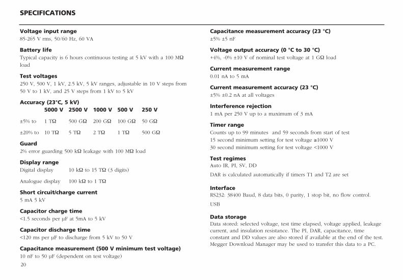
Voltage input range85-265 V rms, 50/60 Hz, 60 VA
Battery lifeTypical capacity is 6 hours continuous testing at 5 kV with a 100 MΩ
load
Test voltages 250 V, 500 V, 1 kV, 2.5 kV, 5 kV ranges, adjustable in 10 V steps from
50 V to 1 kV, and 25 V steps from 1 kV to 5 kV
Accuracy (23°C, 5 kV) 5000 V 2500 V 1000 V 500 V 250 V
±5% to 1 TΩ 500 GΩ 200 GΩ 100 GΩ 50 GΩ
±20% to 10 TΩ 5 TΩ 2 TΩ 1 TΩ 500 GΩ
Guard 2% error guarding 500 kΩ leakage with 100 MΩ load
Display rangeDigital display 10 kΩ to 15 TΩ (3 digits)
Analogue display 100 kΩ to 1 TΩ
Short circuit/charge current 5 mA 5 kV
Capacitor charge time <1.5 seconds per µF at 5mA to 5 kV
Capacitor discharge time<120 ms per µF to discharge from 5 kV to 50 V
Capacitance measurement (500 V minimum test voltage)10 nF to 50 µF (dependent on test voltage)
20
SPECIFICATIONS
Capacitance measurement accuracy (23 °C)±5% ±5 nF
Voltage output accuracy (0 °C to 30 °C) +4%, -0% ±10 V of nominal test voltage at 1 GΩ load
Current measurement range 0.01 nA to 5 mA
Current measurement accuracy (23 °C)±5% ±0.2 nA at all voltages
Interference rejection 1 mA per 250 V up to a maximum of 3 mA
Timer range Counts up to 99 minutes and 59 seconds from start of test
15 second minimum setting for test voltage ≥1000 V
30 second minimum setting for test voltage <1000 V
Test regimesAuto IR, PI, SV, DD
DAR is calculated automatically if timers T1 and T2 are set
Interface RS232: 38400 Baud, 8 data bits, 0 parity, 1 stop bit, no flow control.
USB
Data storage Data stored: selected voltage, test time elapsed, voltage applied, leakage current, and insulation resistance. The PI, DAR, capacitance, time constant and DD values are also stored if available at the end of the test. Megger Download Manager may be used to transfer this data to a PC.
21
ACCESSORIES
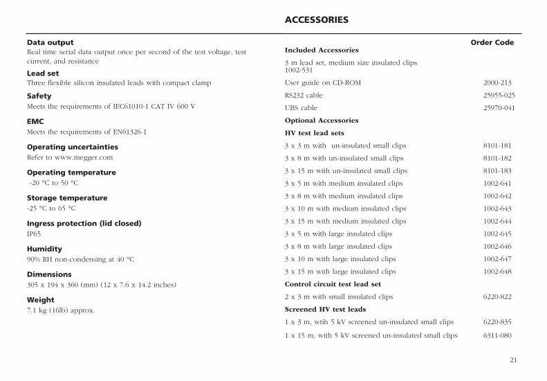
Data output Real time serial data output once per second of the test voltage, test current, and resistance
Lead set Three flexible silicon insulated leads with compact clamp
SafetyMeets the requirements of IEC61010-1 CAT IV 600 V
EMC Meets the requirements of EN61326-1
Operating uncertainties Refer to www.megger.com
Operating temperature -20 °C to 50 °C
Storage temperature-25 °C to 65 °C
Ingress protection (lid closed)IP65
Humidity90% RH non-condensing at 40 °C
Dimensions 305 x 194 x 360 (mm) (12 x 7.6 x 14.2 inches)
Weight7.1 kg (16lb) approx.
Order CodeIncluded Accessories
3 m lead set, medium size insulated clips 1002-531
User guide on CD-ROM 2000-213
RS232 cable 25955-025
UBS cable 25970-041
Optional Accessories
HV test lead sets
3 x 3 m with un-insulated small clips 8101-181
3 x 8 m with un-insulated small clips 8101-182
3 x 15 m with un-insulated small clips 8101-183
3 x 5 m with medium insulated clips 1002-641
3 x 8 m with medium insulated clips 1002-642
3 x 10 m with medium insulated clips 1002-643
3 x 15 m with medium insulated clips 1002-644
3 x 5 m with large insulated clips 1002-645
3 x 8 m with large insulated clips 1002-646
3 x 10 m with large insulated clips 1002-647
3 x 15 m with large insulated clips 1002-648
Control circuit test lead set
2 x 3 m with small insulated clips 6220-822
Screened HV test leads
1 x 3 m, wtih 5 kV screened un-insulated small clips 6220-835
1 x 15 m, with 5 kV screened un-insulated small clips 6311-080
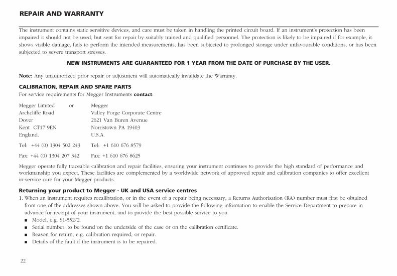
The instrument contains static sensitive devices, and care must be taken in handling the printed circuit board. If an instrument’s protection has been
impaired it should not be used, but sent for repair by suitably trained and qualified personnel. The protection is likely to be impaired if for example, it
shows visible damage, fails to perform the intended measurements, has been subjected to prolonged storage under unfavourable conditions, or has been
subjected to severe transport stresses.
NEW INSTRUMENTS ARE GUARANTEED FOR 1 YEAR FROM THE DATE OF PURCHASE BY THE USER.
Note: Any unauthorized prior repair or adjustment will automatically invalidate the Warranty.
CALIBRATION, REPAIR AND SPARE PARTSFor service requirements for Megger Instruments contact:
Megger Limited or Megger
Archcliffe Road Valley Forge Corporate Centre
Dover 2621 Van Buren Avenue
Kent CT17 9EN Norristown PA 19403
England. U.S.A.
Tel: +44 (0) 1304 502 243 Tel: +1 610 676 8579
Fax: +44 (0) 1304 207 342 Fax: +1 610 676 8625
Megger operate fully traceable calibration and repair facilities, ensuring your instrument continues to provide the high standard of performance and workmanship you expect. These facilities are complemented by a worldwide network of approved repair and calibration companies to offer excellent in-service care for your Megger products.
Returning your product to Megger - UK and USA service centres1. When an instrument requires recalibration, or in the event of a repair being necessary, a Returns Authorisation (RA) number must first be obtained
from one of the addresses shown above. You will be asked to provide the following information to enable the Service Department to prepare in
advance for receipt of your instrument, and to provide the best possible service to you. n Model, e.g. S1-552/2. n Serial number, to be found on the underside of the case or on the calibration certificate. n Reason for return, e.g. calibration required, or repair. n Details of the fault if the instrument is to be repaired.
REPAIR AND WARRANTY
22
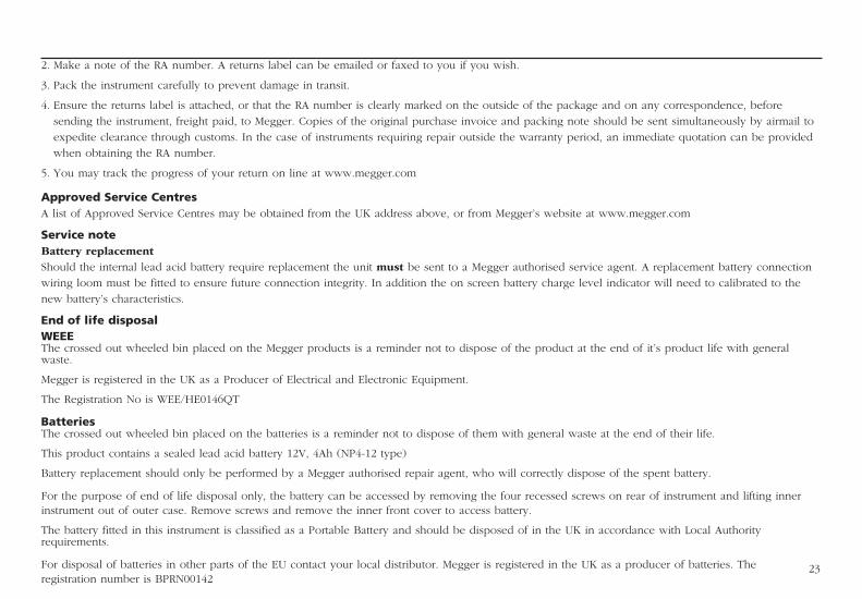
2. Make a note of the RA number. A returns label can be emailed or faxed to you if you wish.
3. Pack the instrument carefully to prevent damage in transit.
4. Ensure the returns label is attached, or that the RA number is clearly marked on the outside of the package and on any correspondence, before
sending the instrument, freight paid, to Megger. Copies of the original purchase invoice and packing note should be sent simultaneously by airmail to
expedite clearance through customs. In the case of instruments requiring repair outside the warranty period, an immediate quotation can be provided
when obtaining the RA number.
5. You may track the progress of your return on line at www.megger.com
Approved Service CentresA list of Approved Service Centres may be obtained from the UK address above, or from Megger’s website at www.megger.com
Service noteBattery replacementShould the internal lead acid battery require replacement the unit must be sent to a Megger authorised service agent. A replacement battery connection
wiring loom must be fitted to ensure future connection integrity. In addition the on screen battery charge level indicator will need to calibrated to the
new battery’s characteristics.
End of life disposalWEEEThe crossed out wheeled bin placed on the Megger products is a reminder not to dispose of the product at the end of it’s product life with general waste.
Megger is registered in the UK as a Producer of Electrical and Electronic Equipment.
The Registration No is WEE/HE0146QT
BatteriesThe crossed out wheeled bin placed on the batteries is a reminder not to dispose of them with general waste at the end of their life.
This product contains a sealed lead acid battery 12V, 4Ah (NP4-12 type)
Battery replacement should only be performed by a Megger authorised repair agent, who will correctly dispose of the spent battery.
For the purpose of end of life disposal only, the battery can be accessed by removing the four recessed screws on rear of instrument and lifting inner instrument out of outer case. Remove screws and remove the inner front cover to access battery.
The battery fitted in this instrument is classified as a Portable Battery and should be disposed of in the UK in accordance with Local Authority requirements.
For disposal of batteries in other parts of the EU contact your local distributor. Megger is registered in the UK as a producer of batteries. The registration number is BPRN00142
23
M
Megger LimitedArchcliffe Road, DoverKent CT17 9EN England T +44 (0)1 304 502101 F +44 (0)1 304 207342E [email protected]
Megger 4271 Bronze Way, Dallas, Texas 75237-1019 USAT +1 800 723 2861 (USA ONLY)T +1 214 333 3201 F +1 214 331 7399E [email protected]
Megger Z.A. Du Buisson de la Couldre 23 rue Eugène Henaff 78190 TRAPPES France T +33 (0)1 30.16.08.90 F +33 (0)1 34.61.23.77 E [email protected]
Megger Pty Limited Unit 1, 11-21 Underwood Road Homebush NSW 2140 Australia T +61 (0)2 9397 5900 F +61 (0)2 9397 5911 E [email protected]
Megger Limited Unit 106-550 Alden Road Markham ON L3R 6A8 Canada T +1 416 298 9688 (Canada only) T +1 416 298 6770 F +1 416 298 0848 E [email protected]
Megger products are distributed in 146 countries worldwide.
This instrument is manufactured in the United Kingdom.The company reserves the right to change the specification or design without prior notice. Megger is a registered trademark
Part No. S1-552_2_UG_en_V10 10/13www.megger.com
Megger 501 Crystal Paradise Mall Off Veera Desai Road Andheri(w), Mumbai - 400053 Maharashtra India T +91 22 26740468 F +91 22 26740465
Megger GmbH Obere Zeil 2 61440 Oberursel Germany T 06171-92987-0 F 06171-92987-19
Megger AB Eldarvägen 4 Box 2970 SE-187 29 TÄBY Sweden T +46 8 510 195 00 F +46 8 510 195 95
Megger AG Ob. Haselweg 630 5727 Oberkulm Aargau Switzerland T +41 62 768 20 30 F +41 62 768 20 33