s. Power Engineering, Plot No. 552, Industrial Area, Phase ... · PDF filePower Engineering,...
73
Electrical Panel Selection Prepared in collaboration with: M/s. Power Engineering, Plot No. 552, Industrial Area, Phase- IX, Mohali Contact Person: Sh. B.S. Verma, 9417233527
Transcript of s. Power Engineering, Plot No. 552, Industrial Area, Phase ... · PDF filePower Engineering,...

Electrical Panel Selection
Prepared in collaboration with:
M/s. Power Engineering,
Plot No. 552, Industrial Area, Phase- IX, Mohali
Contact Person: Sh. B.S. Verma, 9417233527

Typical Power System

Types of Power Connections
• LT < 50KW.
• HT > 50KW.
• Independent feeders 11KV.
• High Voltage Transmission/ Distribution is Preferred • High Voltage Transmission/ Distribution is Preferred
because of Low losses & Reduced size of Conductors
during transmission.
• The power is transmitted at high voltage and low
current.
• The heat generated during transmission is
proportional to current transmission.

� Power (KW/KVA/HP)
� Rated Current.
� System Voltage
� Breaking Capacity
Making Capacity
Selection of Circuit Breaker
� Making Capacity
� Category A or B
� Suitability to site Condition (Indian Condition)
� Maintenance Definitions
� Effect of harmonics

Calculation Formulas

System for HT/ LT connection
• HVPN Supply
• GO Switch
• HT Metering
• VCB
• Transformer
• LT Panel ( Power control centre, Power factor panel,
AMF)
• Distribution Panel
• Sub Distribution panel

Selection Of GO Switch
Gang Operated Switch
Comprises of :- Lightning
Arresters, GO (gang
operated) switch, Drop off operated) switch, Drop off
Fuse(DO), Plate Earthings
two Nos.
for LA (lightening arrestor)
& GO switch.
Selected at 11KV Only.
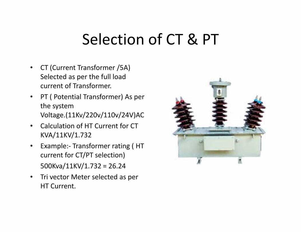
Selection of CT & PT
• CT (Current Transformer /5A)
Selected as per the full load
current of Transformer.
• PT ( Potential Transformer) As per
the system
Voltage.(11Kv/220v/110v/24V)ACVoltage.(11Kv/220v/110v/24V)AC
• Calculation of HT Current for CT
KVA/11KV/1.732
• Example:- Transformer rating ( HT
current for CT/PT selection)
500Kva/11KV/1.732 = 26.24
• Tri vector Meter selected as per
HT Current.

VCB Panel• Vacuum Circuit Breaker
• For Switching carrying
Normal Current and
Breaking abnormal current
at High Voltage.at High Voltage.
• 630A ( Short circuit current)
and Above.
• Over Load, Short Circuit &
E/F protections.
• Measurement of current,
Voltage etc.

Transformer
• 11KV( input)/433V ( Output)
• Selection of Transformer as
per Total load.
• Buckle relay and winding
temperature for safety of temperature for safety of
Transfer. These help to trip
VCB.
• Silica gel to check moisture
content. If blue- Ok, If white
or light pink- replace it.

LT Panels
�PCC--- Power Control Center.
�MCC- Motor Control Center.Center.
�AMF- Auto Mains Failure Panel
�APFC- Automatic Power Factor Correction
�Distribution Panels.

STARTER FOR THREE PHASE
INDUCTION MOTOR
�Starting is a process in which a motor’s rotor is brought from zero speed to rated speed.
�The force to rotate in angular movement is called Torque.called Torque.
�Direct On Line Starters used upto 10 HP
�Star Delta Starterso Manual Star Delta Starters ( not used)
o Automatic Start Delta Starters
o Soft Starters
o VFD

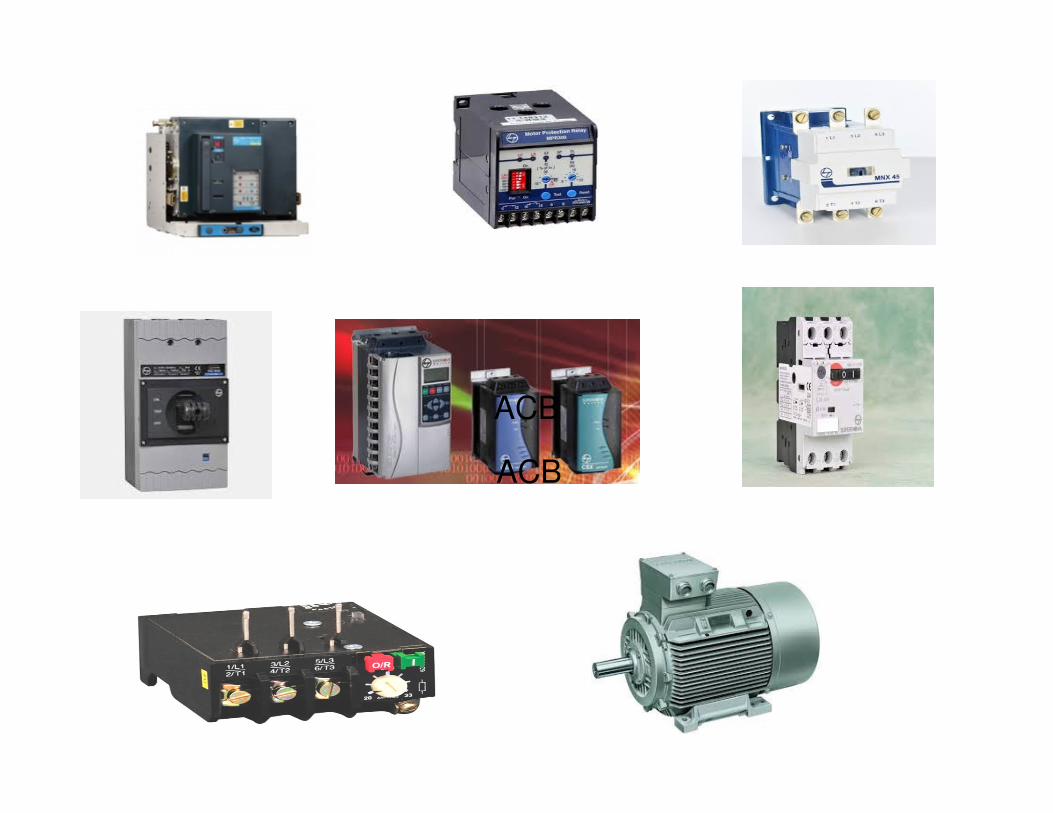
1. Contactors + Over Load + MCCB / MPCB
2. Motor Protection Relay
Starter Panel for Induction Motors
2. Motor Protection Relay
3. On delay Timer + Capacitor Duty Contactor + Capacitors
4. Under Voltage & Over Voltage Relay
5. Hour Meter
6. Time Switch

Components To Be used In Starters
� DOL– MPCB-1No,Contactor- 1No, Push Button 2Nos. On Indication 1 No., single phase preventer 1 No Up to 10HP,
� Star Delta Starter– MCCB 1no, Contactors 3nos,MPR-1no, star-delta Timer 1No, Ammeter with CT 1 No, Push Button 2no, on Indication 1no., single phase preventer 1 Button 2no, on Indication 1no., single phase preventer 1 No.
� Soft Starter- MCCB 1 No, Semiconductor fuses 3 Nos., Line Contactor 1 No, Soft Starter 1 No. ( with built in bye-pass contactor & soft starter selected as per duty or application), Push Button 2 Nos.
� VFD- MCCB 1 No, Semiconductor fuses 3 Nos, VFD1 No.
Push Button 2 Nos. Input/ Out put Chokes.

REDUCTION IN KVA DEMAND DUE TO
POWER FACTOR
LOAD - 900 KW
EXISTING P.F. (COS - 0.6
DESIRED P.F. (COS ) - 0.92 Ø.
Ø 1)
Ø2
KW
KVA 1 = 900 / 0.6 = 1500
KVA2 = 900 / 0.92 = 978
kW
kVACOS =
KVA =
Ø.
kW
cosØ.Reduction in KVA
1500 - 978 = 522

REDUCTION IN LINE
CURRENT
KVA =
I =
I1 =
√3 V I
1000
KVA x 1000
√3 x 415
1500 x 1000
KVA1 - 1500
KVA2 - 978
I1 =
=
I2 =
=
1500 x 1000
√3 x 415
2087 Amp
978 x 1000
√3 x 415
1361 Amp
Reduction in Current
2087 - 1361 = 726

Selection of Capacitor
• Configuration of capacitors1. Individual Compensation2. Group Compensation3. Central Compensation
• KVAR required ( Capacitor)= KVA X √(1- PF ²) - KVA X √(1- PF ²) = KVA X √(1- PF(E)²) - KVA X √(1- PF(T)²)
Existing Power factor from HVPN= PF(E) i.e. 0.6 to 0.75
Target Power factor for system = PF(T) i.e. 0.99

Advantage of Soft Starter
�It starts the motor rotor from zero to designed speed thereby reducing initial load on system.load on system.
�The star Delta starts generally starts with jerk i.e. 30 % of designed speed.
�Soft starters are preferred at high heads.

START
Direct on Line
100
80
60
40
20
0TIME
% VOLTS
Line ContactorOverload
StartStart
RunRun

STARTRun Contactor
Primary
Resistance
100
80
60
40
20
0TIME
% VOLTS
Line Contactor ResistorsOverload
StartStart
RunRun

START
Transformer
Contactor
Star Point
Contactor
Auto-
transformer
100
80
60
40
20
0TIME
% VOLTSLine Contactor Overload
StartStart
RunRun

START
Delta
Contactor
Star Point
Contactor Star -
Delta
100
80
60
40
20
0TIME
% VOLTSLine Contactor Overload
StartStart
RunRun

Soft StartingSTART
% VOLTS
100
80
60
40
20
0
TIME
StartStart
RunRun

IMS2 Product Familiarisation
EBG – Electrical Standard Products
Basics of AC Drives
• Frequency controls Motor speed
• Supply Voltage controls Motor Torque
• Supply Voltage is varied in proportion to
supply frequency so as to keep torque
LARSEN & TOUBRO LIMITED.
supply frequency so as to keep torque
constant

DO’s AND DON’TsDO’s AND DON’TsDO’s AND DON’TsDO’s AND DON’Ts
GOOD TERMINATION PRACTICE
TERMINATION WITH
BUSBAR/LINK

DON’T
DO

DON’T
DODO

DON’T
DODO

DON’T
DO

TERMINATION WITH
LUGS

DON’T
DO

DON’T
DO

DON’T
DO

DON’T
DO

MCB (Miniature Circuit Breaker),
• Rated current not more than 63 A, Thermal or thermal-magnetic operation.

MCCB (Moulded Case Circuit Breaker)
• Rated current above 32 A upto 630 A, Trip
current may be adjustable, Thermal or
thermal-magnetic operation.

Air Circuit Breaker
• Rated current from 800 A upto 6,000 A,
• Trip characteristics often fully adjustable including
configurable trip thresholds and delays.
• Usually electronically controlled—some models are • Usually electronically controlled—some models are
microprocessor controlled.
• Often used for main power distribution in large
industrial plant, where the breakers are arranged in
draw-out enclosures for ease of maintenance.

MCB Selection
• Overload which is intended to prevent the accidental overloading of the cable in a no fault situation. The speed of the MCB tripping will vary with the degree of the overload. This is usually achieved by the use of a thermal device in the MCB.
• The second characteristic is the magnetic fault protection, which is intended to operate when the fault reaches a predetermined level and to trip the MCB within one tenth of a second. The level of this magnetic trip gives the MCB its type characteristic as follows:gives the MCB its type characteristic as follows:
Type Tripping Current Operating Time
Type B ( Domestic) 3 To 5 time full load current 0.04 To 13 Sec
Type C ( Industrial) 5 To 10 times full load current 0.04 To 5 Sec
Type D ( Capacitor) 10 To 20 times full load current 0.04 To 3 Sec

Fuse and MCB characteristics
• The fuse and the MCB, even though their nominal currents are similar, have very different properties.
• For example, For 32Amp MCB and 30 Amp Fuse, to be sure of tripping in 0.1 seconds, the MCB requires a current of 128 amps, while the fuse requires 300 amps.amps.
• The fuse clearly requires more current to blow it in that time, but notice how much bigger both these currents are than the ’30 amps’ marked current rating.
• Fuse require replacement after blowing but MCB only switched on.
ACBACB
ACB

Cable Selection
• Armoured Cables ( For Out door, under ground)
• Unarmoured Cables ( for indoor but open in cable trays)
• Submersible cables
• Size of Cable ( as per load)
• Insulation on cable ( PVC, XLPE)
• Core 3 ( where neutral not required) or 3 ½ cable ( where • Core 3 ( where neutral not required) or 3 ½ cable ( where neutral required)
• 3 core cable in HT, Motor, capacitor
• 3 ½ Core in light load,

Insulation over cable
• Poly Vinyl Chloride
• Cross-Linked Polyethylene (XLPE)- Less
deformation below 100°C, Lower in cost,
Lower dissipation factor, Lower dielectric Lower dissipation factor, Lower dielectric
constant, Higher dielectric strength Physically
tougher, More resistant to chemicals, More oil
resistant

Colour Code for Cables
Single Phase System Three phase System
Live Red Red, Yellow, Blue
Neutral Black Black
Ground Green GreenGround Green Green

EARTHING
BY EARTHING (OR GROUNDING), WE
MEAN MAKING A PHYSICAL AND MEAN MAKING A PHYSICAL AND
ELECTRICAL CONNECTION TO THE
GENERAL MASS OF EARTH.

TYPES OF EARTHING
• SYSTEM EARTHING
• EQUIPMENT EARTHING• EQUIPMENT EARTHING
• LIGHTNING PROTECTION EARTHING
• STATIC EARTHING

SYSTEM EARTHING
SYSTEM EARTHING IS THE EARTHING ASSOCIATED WITH THE CURRENT CARRYING CONDUCTOR (USUALLY THE NEUTRAL POINT OF THE TRANSFORMER OR GENERATOR) AND IS NORMALLY ESSENTIAL FOR THE SECURITY OF THE SYSTEM. THE SYSTEM.
(This is covered by IS 3043:1987
– Code of Practice for Earthing)

EQUIPMENT EARTHING
EQUIPMENT EARTHING IS THE EARTHING ASSOCIATED WITH NON CURRENT CARRYING METAL WORK AND IS ESSENTIAL TO THE SAFETY OF HUMAN LIFE, ANIMALS & PROPERTY. LIFE, ANIMALS & PROPERTY.
(This is covered by IS 3043:1987
– Code of Practice for Earthing)

LIGHTNING PROTECTION EARTHING
LIGHTNING PROTECTION EARTHING IS CONCERNED WITH THE CONDUCTION OF CURRENT DISCHARGES IN ATMOSPHERE ORIGINATING IN CLOUD FORMATIONS TO EARTH AND IS ESSENTIAL FOR THE PROTECTION OF BUILDINGS, FOR THE PROTECTION OF BUILDINGS, TRANSMISSION LINES AND ELECTRICAL EQUIPMENT.
(This is covered by IS 2309:1989
– Protection of buildings and allied structures against lightning – Code of Practice)

SYSTEM EARTHINGWHY ?
� GREATER SERVICE CONTINUITY
� REDUCTION IN OCCURRENCES OF
MULTIPLE FAULTS TO GROUNDMULTIPLE FAULTS TO GROUND
� FEWER ARCING FAULT BURNDOWNS
� EASIER LOCATION OF FAULTS
� GREATER SAFETY
� POSSIBLE SAVING IN COST

EQUIPMENT EARTHINGWHY ?
1. FREEDOM FROM DANGEROUS ELECTRIC
SHOCK HAZARDS
2. REDUCTION IN FIRE HAZARDS2. REDUCTION IN FIRE HAZARDS
3. PRESERVATION OF SYSTEM
PERFORMANCE

REDUCTION IN SHOCK HAZARDSREDUCTION IN SHOCK HAZARDSCASE 1 : NO EQUIPMENT EARTHING
V
LOAD
SOURCE V
LOAD
SOURCE V
SYSTEM
EARTHING
SOURCE V
SYSTEM
EARTHING
SOURCE

REDUCTION IN SHOCK HAZARDSREDUCTION IN SHOCK HAZARDSCASE 3 : EQUIPMENT EARTHING WITH PE CONDUCTOR
V
LOAD
SOURCE V
SYSTEM
EARTHING
SOURCE
EQUIPMENT
EARTHING

Difference between Pipe and Plate Earthing
• Plate earthing costly but reliable.
• Plate earhing is more efficient.
• Less maintenance cost.
• Easy to maintain resistance value.• Easy to maintain resistance value.

• Design Details :
1. Earthing Pit : Size 1000 X 1000 X 1800 mm
Depth.M.S. / C.I. Plate : 500 X 500 X 8 mm
Thick.
2. Electrode Assembly : 40 mm Ø GI / CI
Standard Pipe & Plate Type Earthing Design for the Standard Pipe & Plate Type Earthing Design for the
11 11 KvKv. System Equipments, Distribution Transformer . System Equipments, Distribution Transformer
CentersCenters, L.T. Distribution System Equipments, L.T. Distribution System Equipments
2. Electrode Assembly : 40 mm Ø GI / CI
Perforated pipe duly fitted or welded with base
plate and 50 X 6 mm flat termination taken on
top for equipment earthing as shown in drawing.

4. Mixture - I : Homogeneous mixture of black
soft soil 0.3 CMT. approx.
5. Mixture - II : Homogeneous mixture of
common salt 25 Kgs. + wood charcoal pieces
25 Kgs. + Black soft soil 1 CMT. Approx.
Standard Pipe & Plate Type Earthing Design for the 11 Kv. System Equipments, Distribution Transformer
Centers, L.T. Distribution System Equipments
6. Crushed Rock pieces Gravel Size 50 X 35 mm
0.1 CMT. Approx.
7. Arrangement for earthing lead terminations
from equipment body, and connection for
main earthing Grid.

• Design Details :
1. 75 mm thick RCC Cover.
2. 300 mm Ø 6000 mm deep (Approx. 20 ft.)
bore in the earth.
3. 65 mm Ø 6000 mm long (Approx 20 ft.) G.I.
Typical arrangement for Pipe Typical arrangement for Pipe
electrode earthing pit (Bore Type)electrode earthing pit (Bore Type)
3. 65 mm Ø 6000 mm long (Approx 20 ft.) G.I.
pipe electrode. Forged at the top up to 75 mm
length and 12 mm hole provided for taking
earthing connection.
4. A homogeneous mixture of 50 kgs. wooden
coal pieces + 50 kgs. common salt
5. Water pouring purpose at the time of routine
maintenance

No. of earthing Required
• Equipment Pipe Plate
• GO Switch - 2
• HT metering panel 1 1
• Transformer 1 2• Transformer 1 2
• LT Panel - 2
• Electric Motor 1 -

HP of Motor
HP of Motor= QH/4500/efficiency
Q= Discharge in LPMQ= Discharge in LPM
H= Head of pump in meters
Efficiency varies from 65% to 85%

Motor Start Theory
ME00107A

Type of Insulation and Enclosures for electric
motors
• Insulation Class of winding wire
Class Y- 90°C, Class A- 105°C, Class E- 120°C, Class B- 130°C,
Class H- 180°CClass H- 180°C
To be used as application.
• Enclosures
Screen Protected, screen protected drip proof, Splash proof,
Totally enclosed fan cooled, Totally enclosed and separately
air cooled, totally enclosed air circuit motor, direct ventilated
motor

Descripition of Transformer Capacity
1 KVA of Transformer 100 150 200 250
2 KW of TR. at P.F -0.8 75 125 175 200
3 Full load current of TR. 150 200 250 347
Details of accessories to run the transformer
4 Size of cable 3-core
H.T.side ( Aluminium ) in mm2 35 35 35 355 Size of cable 3 1/2 core
L.T. side(Aluminium ) in mm2 1x185 sqmm 1x240 sqmm 1x240 sqmm 2X185 sqmm
6Metering panel with C.T./P.T unit 15/5 A/110 V 15/5 A/110 V 15/5 A/110 V 15/5 A/110 V
Detail of TRANSFORMER and its Accessories
6 unit 15/5 A/110 V 15/5 A/110 V 15/5 A/110 V 15/5 A/110 V
7Trivector meter as per TR. rating 15/5 A/110 V 15/5 A/110 V 15/5 A/110 V 15/5 A/110 V
8HT VCB/SF-6 panel with HT meteringAs per TR. Rating. NA NA NA NA
9G.O.switch with allaccessories I/C D.O.fuse ,lighting arrestor and stay wireset, earthing etc. Required Required Required Required
10HT current of TR.- on HT side (Amp.) 5.24 7.88 10.5 13.33
11 Impedance % 4 4 4.75 4.75
12Capocitor for TR (KVAR) only for TR losses 4 5 7 10

Descripition of Transformer Capacity
1 KVA of Transformer 315 400 500 630
2 KW of TR. at P.F -0.8 252 320 400 604
3 Full load current of TR. 433 530 687 866
Details of accessories to run the transformer
4 Size of cable 3-core
H.T.side ( Aluminium ) in mm2 35 50 50 50
5 Size of cable 3 1/2 core
L.T. side(Aluminium ) in mm2 2X240 sqmm 2X240 sqmm 3X240 sqmm 3X240 sqmm
6Metering panel with C.T./P.T unit 20/5 A/110 V 25/5 A/110 V 30/5 A/110 V 50/5 A/110 V
7Trivector meter as per TR. rating 20/5 A/110 V 25/5 A/110 V 30/5 A/110 V 50/5 A/110 V7 rating 20/5 A/110 V 25/5 A/110 V 30/5 A/110 V 50/5 A/110 V
8HT VCB/SF-6 panel with HT metering
As per TR. Rating. Required Required Required Required
9G.O.switch with allaccessories I/C D.O.fuse ,lighting arrestor and stay wireset, earthing etc. Required Required Required Required
10HT current of TR.- on HT side (Amp.) 16.8 21.33 26.66 40.26
11 Impedance % 4.75 4.75 4.75 5
12Capocitor for TR (KVAR) only for TR losses 12.5 20 25 30

Descripition of Transformer Capacity
1 KVA of Transformer 800 1000 1250 1600 2000
2 KW of TR. at P.F -0.8 640 800 1000 1280 1600
3 Full load current of TR. 1100 1375 1718 2199 2740
Details of accessories to run the transformer
4 Size of cable 3-core
H.T.side ( Aluminium ) in mm2 70 70 95 125 125
5 Size of cable 3 1/2 core Bus duct 1200
ABus duct 1600
ABus duct 2000
ABus duct 2500
ABus duct 4000
AL.T. side(Aluminium ) in mm2 3X400 sqmm 4X400 sqmm N/A N/A N/A
Metering panel with C.T./P.T 6
Metering panel with C.T./P.T unit 50/5 A/110 V 60/5 A/110 V 70/5 A/110 V 100/5 A/110 V 125/5 A/110 V
7Trivector meter as per TR. rating 50/5 A/110 V 60/5 A/110 V 70/5 A/110 V 100/5 A/110 V 125/5 A/110 V
8HT VCB/SF-6 panel with HT metering
As per TR. Rating. Required Required Required Required Required
9G.O.switch with allaccessories I/C D.O.fuse ,lighting arrestor and staywire set, earthing etc. Required Required Required Required Required
10HT current of TR.- on HT side (Amp.) 42.66 53.33 66.66 85.33 106.66
11 Impedance % 5 5 5 6.25 6.25
12Capocitor for TR (KVAR) only for TR losses 35 50 50 75 100
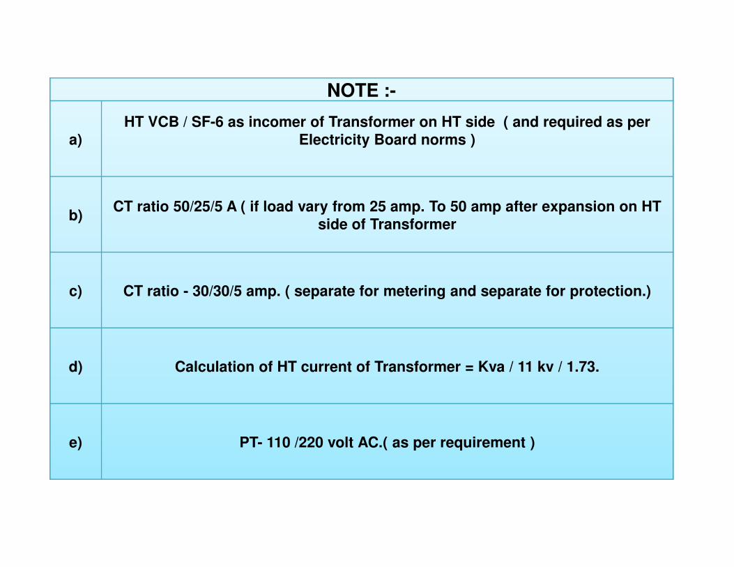
NOTE :-
a)
HT VCB / SF-6 as incomer of Transformer on HT side ( and required as per
Electricity Board norms )
b) CT ratio 50/25/5 A ( if load vary from 25 amp. To 50 amp after expansion on HT
side of Transformer
c) CT ratio - 30/30/5 amp. ( separate for metering and separate for protection.) c) CT ratio - 30/30/5 amp. ( separate for metering and separate for protection.)
d) Calculation of HT current of Transformer = Kva / 11 kv / 1.73.
e) PT- 110 /220 volt AC.( as per requirement )

Detail of D.G.Sets with details
1 KVA 5 7.5 10 15 15 20 25 30 30 40 50 62.5 62.5 75 82.5
2 KW 4 6 8 12 12 16 20 24 24 32 40 50 50 60 66
3 AMPS 6.95 10.4 13.9 20.8 20.8 27.8 34.75 41.7 41.7 55.6 69.5 86.9 86.9 104 114.6
4 BHP 7 10 12 18.7 19 28 32 38 43 50.5 65 76 83 105 105
1 KVA 100 125 160 180 200 250 320 380 437 500 625 750 1000
2 KW 80 100 128 144 160 200 256 304 350 400 500 600 800
3 AMPS 139 173.7 222.4 250 278 348 445 528 608 614 868.8 1043 1390
4 BHP 127 154 205 231 255 306 380 450 530 614 750 890 1180

Detail of DIRECT ON LINE ( DOL ) starter with all type of possible accessories
S.No.DESCREPTION OF MOTOR
1 HP-3Phase 415 V AC 0.5 0.75 1 1.52 KW of Motor 0.37 0.55 0.75 1.13 Full load current of Motor
in amp. 1.2 1.6 1.8 2.6
EQUIPMENT TO START THE MOTOR BELOW FOR EACH MOTOR4 MPCB as incomer. In amp. MPCB MPCB MPCB MPCB
1-1.6 A 1-1.6 A 1.6-2.5 A 2.5-4 A5 Contactor rating in amp. 1x9 amp 1x9 amp 1x9 amp 1x9 amp6 Single phase preventor 415 v 6 Single phase preventor 415 v
AC. A/P/R A/P/R A/P/R A/P/R7 Control MCB SP.( single pole
) 6 amp SP 6 amp SP 6 amp SP 6 amp SP8 Push Botton ( START &
STOP ) 1 NO+1 NC 2-Nos 2-Nos 2-Nos 2-Nos9 On Indication ( LED 220 V
AC ) 1-Nos 1-Nos 1-Nos 1-Nos10 Cable for supply side 3 1/2
core COPPER 1.5 sq mm 1.5 sq mm 1.5 sq mm 1.5 sq mm11 Cable for Motor side 3-core
COPPER. 1.5 sq mm 1.5 sq mm 1.5 sq mm 1.5 sq mm

Detail of DIRECT ON LINE ( DOL ) starter with all type of possible accessories
S.No.
DESCREPTION OF MOTOR
1 HP-3Phase 415 V AC 2 3 5 7.5 102 KW of Motor 1.5 2.25 3.75 5.5 7.53 Full load current of
Motor in amp. 3.5 5 7.5 11 14
EQUIPMENT TO START THE MOTOR BELOW FOR EACH MOTOR4 MPCB as incomer. In
amp. MPCB MPCB MPCB MPCB MPCB
2.5-4 A 4-6.3 A 6-10 A 9-15 A 9-15 A5 Contactor rating in amp. 1x9 amp 1x9 amp 1x12 amp 1x18 amp 1x25 amp5 Contactor rating in amp. 1x9 amp 1x9 amp 1x12 amp 1x18 amp 1x25 amp6 Single phase preventor
415 v AC. A/P/R A/P/R A/P/R A/P/R A/P/R7 Control MCB SP.( single
pole ) 6 amp SP 6 amp SP 6 amp SP 6 amp SP 6 amp SP8 Push Botton ( START &
STOP ) 1 NO+1 NC 2-Nos 2-Nos 2-Nos 2-Nos 2-Nos9 On Indication ( LED 220
V AC ) 1-Nos 1-Nos 1-Nos 1-Nos 1-Nos10 Cable for supply side 3
1/2 core COPPER 2.5 sq mm 2.5 sq mm 2.5 sq mm 4 sq mm 4 sq mm11 Cable for Motor side 3-
core COPPER. 2.5 sq mm 2.5 sq mm 2.5 sq mm 4 sq mm 4 sq mm
Single phase preventor 415 v AC = A/P/R ( AS PER REQUIRMENT )

S.No.DESCREPTION OF MOTOR
1 HP-3Phase 415 V AC 15 20 25 30 35
2 KW of Motor 11 15 18.5 22 26
3Full load Line current of Motor in amp. 21 28 35 40 47
4Phase current of Motor in amp. 12 16 20 23 27
EQUIPMENT TO START THE MOTOR BELOW FOR EACH MOTOR
5MPCB/MCCB as incomer. In amp. MPCB MPCB MCCB MCCB MCCB
19-25 A 24-32 A 63 A 100 A 100 A
Detail of STAR/DELTA starter with all type of possible accessories
19-25 A 24-32 A 63 A 100 A 100 A6 Contactor rating in amp. 3x25 amp 3x32 amp 3x32 amp 3x40 amp 3x40 amp
7 Motor protection relay -MPR Not-req Not-req MPR MPR MPR ( 2.5-5 A ) ( 2.5-5 A ) ( 2.5-5 A )
8 Timers 0-60 sec 0-60 sec 0-60 sec 0-60 sec 0-60 sec
9Single phase preventor 415 v AC. A/P/R A/P/R A/P/R A/P/R A/P/R
10 Control MCB SP. 6 amp SP 6 amp SP 6 amp SP 6 amp SP 6 amp SP
11 Amp. Meter 0-50 amp 0-50 amp 0-50 amp 0-50 amp 0-75 amp12 CT,s ( -/5 amp ) 50/5 amp 50/5 amp 50/5 amp 50/5 amp 75/5 amp
13Cable for supply side 3 1/2 core ALUMINIUM 10 sq mm 10 sq mm 16 sq mm 16 sq mm 25 sq mm
14Cable for Motor side 3-core ALUMINIUM. 2x6 sq mm 2x6 sq mm 2x10 sq mm 2x10 sq mm 2x16 sq mm

S.No.DESCREPTION OF MOTOR
1 HP-3Phase 415 V AC 40 50 60 75 90
2 KW of Motor 30 37 45 56 67.5
3Full load line current of Motor in amp. 55 66 80 100 120
4Phase current of Motor in amp. 30 35 45 57 69
EQUIPMENT TO START THE MOTOR BELOW FOR EACH MOTOR
5MPCB/MCCB as incomer. In amp. MCCB MCCB MCCB MCCB MCCB
100 A 100 A 125 A 160 A 200 A
Detail of STAR/DELTA starter with all type of possible accessories
100 A 100 A 125 A 160 A 200 A
6 Contactor rating in amp. 3x40 amp 3x50 amp 3x70 amp 3x80 amp 3x110amp
7 Motor protection relay -MPR MPR MPR MPR MPR MPR
( 2.5-5 A ) ( 2.5-5 A ) ( 2.5-5 A ) ( 2.5-5 A ) ( 2.5-5 A )
8 Timers 0-60 sec 0-60 sec 0-60 sec 0-60 sec 0-60 sec
9Single phase preventor 415 v AC. A/P/R A/P/R A/P/R A/P/R A/P/R
10 Control MCB SP. 6 amp SP 6 amp SP 6 amp SP 6 amp SP 6 amp SP
11 Amp. Meter 0-75 amp 0-100 amp 0-100 amp 0-150 amp 0-150 amp
12 CT,s ( -/5 amp ) 75/5 amp 100/5 amp 100/5 amp 150/5 amp 150/5 amp
13Cable for supply side 3 1/2 core ALUMINIUM 25 sq mm 35 sq mm 50 sq mm 70 sq mm 70 sq mm
14Cable for Motor side 3-core ALUMINIUM. 2x16 sq mm 2x16 sq mm 2x25 sq mm 2x25 sq mm 2x50 sq mm

Detail of STAR/DELTA starter with all type of possible accessories
S.No.DISCREPTION OF MOTOR
1 HP-3Phase 415 V AC 100 125 150 175 200 250
2 KW of Motor 75 90 112 132 150 187
3Full load line current of Motor in amp. 135 165 200 230 275 323
4Phase current of Motor in amp. 78 95 115 133 159 185
EQUIPMENT TO START THE MOTOR BELOW FOR EACH MOTOR
5MPCB/MCCB as incomer. In amp. MCCB MCCB MCCB MCCB MCCB MCCB
250 A 250 A 400 A 400 A 400 A 630A
6 Contactor rating in amp. 3x110amp 3x140amp 3x140amp 3x200amp 3x200amp 3x265amp
7Motor protection relay -MPR MPR MPR MPR MPR MPR MPR
( 2.5-5 A ) ( 2.5-5 A ) ( 2.5-5 A ) ( 2.5-5 A ) ( 2.5-5 A ) ( 2.5-5 A )
8 Timers 0-60 sec 0-60 sec 0-60 sec 0-60 sec 0-60 sec 0-60 sec
9Single phase preventor 415 v AC. A/P/R A/P/R A/P/R A/P/R A/P/R A/P/R
10 Control MCB SP. 6 amp SP 6 amp SP 6 amp SP 6 amp SP 6 amp SP 6 amp SP
11 Amp. Meter 0-150 amp 0-250 amp 0-250 amp 0-250 amp 0-400 amp 0-400 amp
12 CT,s ( -/5 amp ) 150/5 amp 250/5 amp 250/5 amp 250/5 amp 400/5 amp 400/5 amp
13Cable for supply side 3 1/2 core ALUMINIUM 95 sq mm 120 sq mm 240 sq mm 240 sq mm
2x120 sq mm
2x150 sq mm
14Cable for Motor side 3-core ALUMINIUM.
2x50 sq mm
2x70 sq mm 2x95 sq mm 2x95 sq mm
2x120 sq mm
2x185 sq mm
IMPORTANT - ALL THE POWER CONNECTION OF STARTER IN SIDE THE PANEL WITH SOLID BUS BARS 50 HP AND ABOVE.

VIDEO ON STAR - DELTA STARTER

160KVAPower of the transformer
500
KVA
250KVA48.0 KA =Icc downstream
the transformer
400KVA
630KVAMaine line (Alu or Copper)
800KVAa=alu (cu by default) a
1000KVALenght 5 m
1250KVACross section 800 mm²
1600KVA45.3KA45.3KA
2000KVA
2500KVASecundary level (Alu or Copper)
a=alu (cu by default) aLenght 10 m
Cross section 240 mm²
33.1 KA
third level (Alu or Copper)
a=alu (cu by default)Lenght 20 m
Cross section 1.5 mm²
Icc3 = 0.75 KA
Icc1 = 0.60 KA

Thank YouThank You