S E C T I O N 1 RBM84 - hardware - EasyGates Ltdmanuals.easygates.co.uk/PDF/CAME/rbm84 complete...
81
CONTENTS subject page RBM84 Motherboard - description 2 REM Motherboard - description ........................................................................................ 3 PC30 - description ........................................................................................................... 4 General layout RBM84 system ......................................................................................... 5 RBM84 Connection <----> PC30 <----> Personal Computer .................................................. 6 RBM84 Connection <----> REM (one section) ...................................................................... 7 RBM84 Connection <----> REM (two sections) ...................................................................... 8 RBM84/REM Connection <---> sensor: REMOTE CONTROL .................................................. 9 RBM84/REM Connection <---> Keyboard selector, series S5000 ......................................... 10 RBM84/REM Connection <---> Keyboard selector, series S6000/S7000 ............................... 11 RBM84/REM Connection <---> Sensor transponder for proximity devices ............................ 12 RBM84/REM Connection <---> Sensor for magnetic swipe cards ......................................... 13 RBM84/REM Connection <---> Digital entrance contacts .................................................... 14 List of REM addresses ................................................................................................. 15 RBM84 - hardware S E C T I O N 1
Transcript of S E C T I O N 1 RBM84 - hardware - EasyGates Ltdmanuals.easygates.co.uk/PDF/CAME/rbm84 complete...

CONTENTSsubject page
RBM84 Motherboard - description 2
REM Motherboard - description ........................................................................................ 3
PC30 - description ........................................................................................................... 4
General layout RBM84 system ......................................................................................... 5
RBM84 Connection <----> PC30 <----> Personal Computer .................................................. 6
RBM84 Connection <----> REM (one section) ...................................................................... 7
RBM84 Connection <----> REM (two sections) ...................................................................... 8
RBM84/REM Connection <---> sensor: REMOTE CONTROL .................................................. 9
RBM84/REM Connection <---> Keyboard selector, series S5000 ......................................... 10
RBM84/REM Connection <---> Keyboard selector, series S6000/S7000 ............................... 11
RBM84/REM Connection <---> Sensor transponder for proximity devices ............................ 12
RBM84/REM Connection <---> Sensor for magnetic swipe cards ......................................... 13
RBM84/REM Connection <---> Digital entrance contacts .................................................... 14
List of REM addresses ................................................................................................. 15
RBM84 - hardware
S E C T I O N 1
Cap
1
Hardware - CONNECTIONS
cap. < 1 > pag.< 2 >
ENGLISCH
FUSE
630m
A
12
34
56
78
910
1112
0304
0506
07V1
V2V3
V4V5
CONTR
OL
BOARD
PSIO1
TRANSFORM ER TERM INAL B LOC K
LINE FUSE 5A
C AM EU2
REM REM PC 30
LT001 R501/2S5000S6000S7000
DIGITAL INPUT
1
2
3
4
TSP00LT001
S5000S6000S7000
TSP00 R501/2
BATTERYCHARGER BN1
A B C D
BATTERY
R700-R800
1
R700-R800
2
R700-R800
3
R700-R800
4
R700
-R8
00
1
R700
-R8
00
2
R700
-R8
00
3
R700
-R8
00
4
MODE
MMODEM
A B S1GNDOUT
NO CNC
O UT 3
A B GND NO CNC
O UT 4
A B GND NO CNC
O UT 5
A B GND NO CNC
O UT 6
A B GND NO CNC
O UT 7
A B GND NO CNC
O UT 8
A B GNDNC NO C
O UT 1
A B GND NONC C
O UT 2
A B GND
2 1345
ON
L NL N
P1 P2 P3 P4Com ComP5 P6 P7 P8 A B GNDA B GNDA B GND
A B S1GNDOUT
A B S1GNDOUTA B S1GNDOUT
10
9
8
76
5
4
3
2
1
11
12
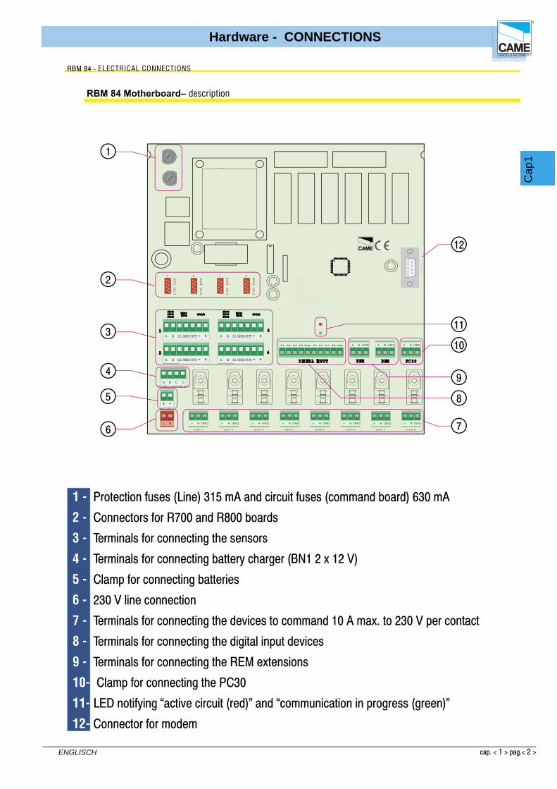
RBM 84 Motherboard– description
RBM 84 - ELECTRICAL CONNECTIONS
1 - Protection fuses (Line) 315 mA and circuit fuses (command board) 630 mA
2 - Connectors for R700 and R800 boards
3 - Terminals for connecting the sensors
4 - Terminals for connecting battery charger (BN1 2 x 12 V)
5 - Clamp for connecting batteries
6 - 230 V line connection
7 - Terminals for connecting the devices to command 10 A max. to 230 V per contact
8 - Terminals for connecting the digital input devices
9 - Terminals for connecting the REM extensions
10- Clamp for connecting the PC30
11- LED notifying “active circuit (red)” and “communication in progress (green)”
12- Connector for modem

Cap
1
Hardware - CONNECTIONS
cap. < 1 > pag.< 3 >
ENGLISCH
CANCELLI AUTOMATICI
CONTROLBOARD
REM
OUT1
NC NO CL2L1
1 2OUT2
NC NO C
21
1-
AF
43S
/AF
150/
R70
0/R
800
2-
AF
43S
/AF
150/
R70
0/R
800
LIN
EF
US
E1,
6A
CONTROL BOARDFUSE 630mA
21 3 4 5
ON
A B A B
1 2
S5000/S6000/S7000
S1 GND S1 GND
1 2
TSP00/LT001
A B GND
1
REM
A B GND
2
REM
1 8
2
5
4
6
11
9
10
3
47
1 - Terminals for powering board, 230 V2 - Power protection fuse3 - Circuit protection fuse 4 - Terminals for connecting sensors (keyboards, readers)5 - Board connectors for signal decoding (sensors, remote controls)6 - Terminals for connecting antenna7 - Terminals for connecting the digital input devices 8 - Terminals for connecting the devices to command9 - LED notifying “communication active”10- REM addresses selector11- Terminals for connecting to other REMs or RBM84
5
ON
4321
ON
4321
REM Motherboard – description
RBM 84 - ELECTRICAL CONNECTIONS

Cap
1
Hardware - CONNECTIONS
cap. < 1 > pag.< 4 >
ENGLISCH
3 2 1
11
10 9
7
68 5
4
1 - Power input, 12 V A.C.2 - RS232 serial port for connecting to a Personal Computer3 - Terminals for connection to RBM84 (RS485 serial port)4 - 12 V A.C. transformer5 - Cable complete with 1.5 m RS232 connectors 6 - Keyboard for saving selector codes S5000/S6000/S70007 - Area for memorizing transmitters TAM/ATOMO8 - Area for memorizing Card TST01 (proximity cards)9 - Area for memorizing Card TST02 (magnetic swipe cards)10- LED notifying “supply presence”11- LED notifying “registered code “ and “code already present”
PC30 - description
RBM 84 - ELECTRICAL CONNECTIONS

Cap
1
Hardware - CONNECTIONS
cap. < 1 > pag.< 5 >
ENGLISCH
PC30
A
A C
C
BB
C
B
B
AA
C
REM
C
CC
C C C C C
B
B
B
B
BB
BBA
AA
A
RBM84
C
CA
BB
A
REM
C
CB
B
AA
REM
REM
max 1000 m
max 1000 m
max 60 REM units for both typesof serial connection�
A = Control devices: - radio transmitters Atomo/Tam - keypads S5000/S6000/S7000 - sensorsTSP00/LT001
B = Outputs (automation control)�
= Digital imputs :
max 1,5 m
max 1000 m
C
B
A
CAME
CAME
CAME
CAME
single connetion
double connection
General system layout
RBM 84 - ELECTRICAL CONNECTIONS

Cap
1
Hardware - CONNECTIONS
cap. < 1 > pag.< 6 >
ENGLISCH
FUSE
630m
A
12
34
56
78
910
1112
0304
0506
07V1
V2V3
V4V5
CONTR
OL
BOARD
PSIO1
TRANSFORM ER TERM INAL B LOC K
LINE FUSE 5A
C AM EU2
REM REM PC 30
LT001 R501/2S5000S6000S7000
DIGITAL INPUT
1
2
3
4
TSP00LT001
S5000S6000S7000
TSP00 R501/2
NO CNC NO CNC NO CNC NO CNC NO CNC NO CNCNC NO C NONC CL N
A B GNDA B GNDA B GND
RS232
PC30
RBM 84
COM
GND B A
Cable, 1.5mINCLUDEDfor RS232 serial portscomplete with connectors
12 V AC transformerINCLUDED
for networks 230 V A.C. - 50-60Hzconsumption 800 mA
protected by thermal fuseoperating temperature from -10 to +40°C
rbm84 connection <----> PC30 <----> Personal Computer
RBM 84 - ELECTRICAL CONNECTIONS
Cable not includedtype recommended:
shielded bipolarmin. 2 x 0.5 mm2
Cap
1
Hardware - CONNECTIONS
cap. < 1 > pag.< 7 >
ENGLISCH
FUSE
630m
A
12
34
56
78
910
1112
0304
0506
07V1
V2V3
V4V5
CONTR
OL
BOARD
PSIO1
TRANSFORM ER TERM INAL B LOC K
LINE FUSE 5A
C AM EU2
REM REM PC 30
LT001 R501/2S5000S6000S7000
DIGITAL INPUT
1
2
3
4
TSP00LT001
S5000S6000S7000
TSP00 R501/2
NO CNC NO CNC NO CNC NO CNC NO CNC NO CNCNC NO C NONC CL N
om A B GNDA B GNDA B GND
CAME
REM
RBM84
REM
REM
REM
CAME
CAME
CAME
CAME
RBM 84
REM
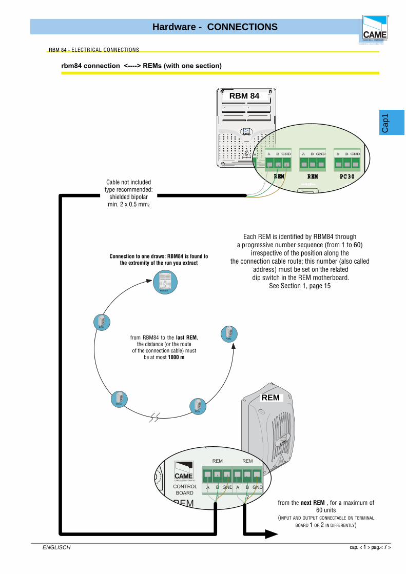
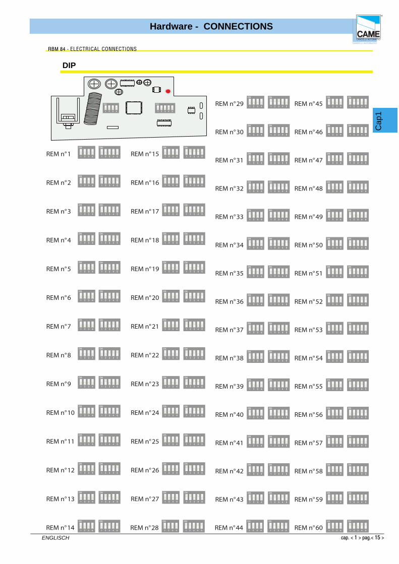
from the next REM , for a maximum of 60 units
(INPUT AND OUTPUT CONNECTABLE ON TERMINAL
BOARD 1 OR 2 IN DIFFERENTLY)
Each REM is identifi ed by RBM84 througha progressive number sequence (from 1 to 60)
irrespective of the position along the the connection cable route; this number (also called
address) must be set on the related dip switch in the REM motherboard.
See Section 1, page 15
from RBM84 to the last REM, the distance (or the route
of the connection cable) mustbe at most 1000 m
Connection to one draws: RBM84 is found to the extremity of the run you extract
rbm84 connection <----> REMs (with one section)
CANCELLI AUTOMATICI
CONTROLBOARD
REM
21
S5000/S6000/S7000
1 2
A B GND
1
REM
A B GND
2
REM
Cable not includedtype recommended:
shielded bipolarmin. 2 x 0.5 mm2
RBM 84 - ELECTRICAL CONNECTIONS

Cap
1
Hardware - CONNECTIONS
cap. < 1 > pag.< 8 >
ENGLISCH
REM
RBM84
REM
REM
REM
CAME
rbm84 connection <----> REMs (with two sections)
CAME
CAME
CAME
FUSE
630m
A
12
34
56
78
910
1112
0304
0506
07V1
V2V3
V4V5
CONTR
OL
BOARD
PSIO1
TRANSFORM ER TERM INAL B LOC K
LINE FUSE 5A
C AM EU2
REM REM PC 30
LT001 R501/2S5000S6000S7000
DIGITAL INPUT
1
2
3
4
TSP00LT001
S5000S6000S7000
TSP00 R501/2
NO CNC NO CNC NO CNC NO CNC NO CNC NO CNCNC NO C NONC CL N
om A B GNDA B GNDA B GND
RBM 84
RBM 84 - ELECTRICAL CONNECTIONS
from the next REM , for a maximum of 60 units
(INPUT AND OUTPUT CONNECTABLE ON TERMINAL
BOARD 1 OR 2 IN DIFFERENTLY)
* the sum of the serial connected REMs on the A+B section must be 60 units max.
trat
ta A
*
Each REM is identifi ed by RBM84 througha progressive number sequence (from 1 to 60)
irrespective of the position along the connection cable route; this number (also called
address) must be set on the related dip switch selector in the REM motherboard.
See Section 1, page 15 for the subsequent REM
(INPUT AND OUTPUT CONNECTABLE ON TERMINAL BOARD
1 O 2 INDIFFERENTLY)
Connection to two drawn: RBM84 can be in any point of the run extracts
from the fi rst to thelast REM, the distance (or the route
of the connection cable) mustbe a maximum of 1,000 m
CANCELLI AUTOMATICI
CONTROLBOARD
REM
21
S5000/S6000/S7000
1 2
A B GND
1
REM
A B GND
2
REM
CANCELLI AUTOMATICI
CONTROLBOARD
REM
21
S5000/S6000/S7000
1 2
A B GND
1
REM
A B GND
2
REM
trat
ta B
Cable not includedtype recommended:
shielded bipolarmin. 2 x 0.5 mm2
Cable not includedtype recommended:
shielded bipolarmin. 2 x 0.5 mm2
from the next REM , for a maximum of 60 units
(INPUT AND OUTPUT CONNECTABLE ON TERMINAL
BOARD 1 OR 2 IN DIFFERENTLY)
Cap
1
Hardware - CONNECTIONS
cap. < 1 > pag.< 9 >
ENGLISCH
CAME
21
1-
AF
43S
/AF
150/
R
2-
AF
43S
/AF
150/
R
S1 GND S1
1
TSP00/LT0
REM REM
FUSE
630m
A
12
34
56
78
910
1112
0304
0506
07V1
V2V3
V4V5
CONTR
OL
BOARD
PSIO1
TRANSFORM ER TERM INAL B LOC K
LINE FUSE 5A
C AM EU2
REM REM PC 30
LT001 R501/2S5000S6000S7000
DIGITAL INPUT
1
2
3
4
TSP00LT001
S5000S6000S7000
TSP00 R501/2
R700-R800
1
R700-R800
2
R70
0-
R80
0
1
R70
0-
R80
0
2
NO CNC NO CNC NO CNC NO CNC NO CNC NO CNCNC NO C NONC CL N
A B S1GNDOUT
CAME
CAME
CAME
T432
T434
T438
T432A
CAME
CAME
CAME
AT01
AT02
AT04
RB
M84
RE
M
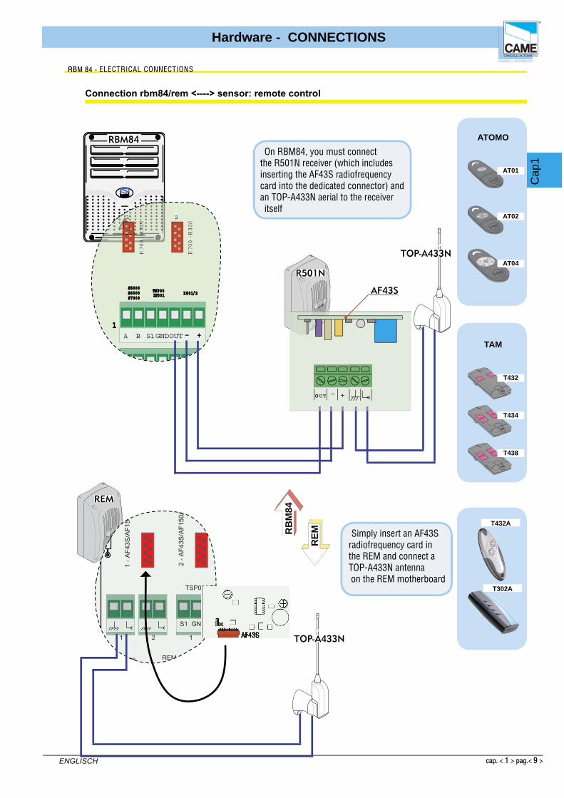
Connection rbm84/rem <----> sensor: remote control
RBM84
TOP-A433N
REM
CAME
OOUT +-
R501N
AF43S
TOP-A433N
T302A
RBM 84 - ELECTRICAL CONNECTIONS
Simply insert an AF43S radiofrequency card in the REM and connect a TOP-A433N antenna on the REM motherboard
On RBM84, you must connect the R501N receiver (which includes inserting the AF43S radiofrequency card into the dedicated connector) and an TOP-A433N aerial to the receiver itself
TAM
ATOMO

Cap
1
Hardware - CONNECTIONS
cap. < 1 > pag.< 10 >
ENGLISCH
012
1
4
7
5
8
3
6
E
CANCELLIAUTOM ATICI
CO NTROLBOARD
REM
1 2
C
21
1-AF4
AF150
2-AF43S/AF15
S5
S1 G ND S1 GND
1 2
TSP00/LT001
A B G
1
REM REM
012
1
4
7
5
8
3
6
E
RBM84
FUSE
630m
A
12
34
56
78
910
1112
0304
0506
07V1
V2V3
V4V5
CONTR
OL
BOARD
PSIO1
TRANSFORM ER TERM INAL B LOC K
LINE FUSE 5A
C AM EU2
REM REM PC 30
LT001 R501/2S5000S6000S7000
DIGITAL INPUT
1
2
3
4
TSP00LT001
S5000S6000S7000
TSP00 R501/2
R700-R800
R700-R800
2
R70
0-
R80
0
R70
0-
R80
0
2
NO CNC NO CNC NO CNC NO CNC NO CNC NO CNCNC NO C NONC CL N
RB
M84
RE
M
CANCELLI AUTOMATICI
R800
CANCELLI AUTOMATICI
R800
REM
S5000
S5000
Connection rbm84/rem <----> Keyboard selector serious S5000
RBM 84 - ELECTRICAL CONNECTIONS

Cap
1
Hardware - CONNECTIONS
cap. < 1 > pag.< 11 >
ENGLISCH
1
2
6
E3
54
CAME
RE
M
RBM84
FUSE
630m
A
12
34
56
78
910
1112
0304
0506
07V1
V2V3
V4V5
CONTR
OL
BOARD
PSIO1
TRANSFORM ER TERM INAL B LOC K
LINE FUSE 5A
C AM EU2
REM REM PC 30DIGITAL INPUT
1
2
3
4
LT001
S5000S6000S7000
TSP00 R501/2
R700-R800
R700-R800
2
R70
0-
R80
0
R70
0-
R80
0
2
NO CNC NO CNC NO CNC NO CNC NO CNC NO CNCNC NO C NONC CL N
CANCELLI AUTOMATICI
R800
CANCELLIAUTOM ATICI
CO NTROLBOARD
REM
1 2
C
21
1-AF4
AF150
2-AF43S/AF15
S
S1 G ND S1 GND
1 2
TSP00/LT001
A B G
1
REM REM
REM
CANCELLI AUTOMATICI
R800
1
2
6
E3
54
CAME
A
B
S6000 / S7000
S6000 / S7000
B
A
Connection rbm84/rem <----> Keyboard selector serious S6000 / S7000
RBM 84 - ELECTRICAL CONNECTIONS
Cap
1
Hardware - CONNECTIONS
cap. < 1 > pag.< 12 >
ENGLISCH
RB
M84
CAM E
CAM E
CANCELLIAUTOM ATICI
CO NTROLBOARD
REM
21
1-AF4
AF150
2-AF43S/AF1
S1
TS
A B
1
REM
FUSE
630m
A
12
34
56
78
910
1112
0304
0506
07V1
V2V3
V4V5
CONTR
OL
BOARD
PSIO1
TRANSFORM ER TERM INAL B LOC K
LINE FUSE 5A
C AM EU2
REM REM PC 30
S5000S6000S7000
DIGITAL INPUT
1
2
3
4
LT001
S5000S6000S7000
TSP00 R501/2
R700-R800
R70
0-
R80
0
11
NO CNC NO CNC NO CNC NO CNC NO CNC NO CNCNC NO C NONC CL N
A B
1
CAM E
CAM E
CANCELLI AUTOMATICI
R700
R700
Proxmimity card reader
Proxmimity card
REM
RBM84
TSP00
TST01
TSP00
TST01
GND
GND
S1
Proxmimity card reader Proxmimity card
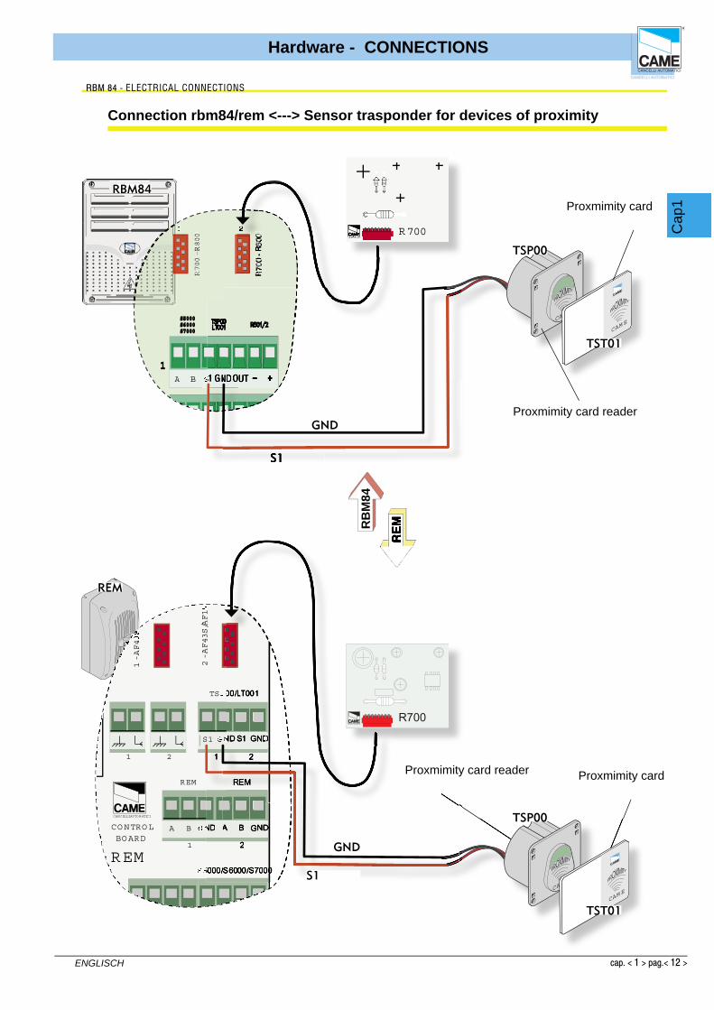
Connection rbm84/rem <---> Sensor trasponder for devices of proximity
RBM 84 - ELECTRICAL CONNECTIONS

Cap
1
Hardware - CONNECTIONS
cap. < 1 > pag.< 13 >
ENGLISCH
21
1-AF43S/AF150/R700/R800 0
S1 G ND S1 GND
RB
M84
RE
M
R700
FUSE
630m
A
12
34
56
78
910
1112
0304
0506
07V1
V2V3
V4V5
CONTR
OL
BOARD
PSIO1
TRANSFORM ER TERM INAL B LOC K
LINE FUSE 5A
C AM EU2
REM REM PC 30
S7000
DIGITAL INPUT
1
2
3
4
LT001
S5000S6000S7000
TSP00 R501/2
1111
NO CNC NO CNC NO CNC NO CNC NO CNC NO CNCNC NO C NONC CL N
A B S1GNDOUT
1
RBM84
ACCESSCONTROL
TST02
LT001
GND
S1
REM
ACCESSCONTROL
TST02
LT001
Magnetic cards
GND
S1
R700
Magnetic cards swipe reader
Magnetic cards
rbm84/rem connection <----> Sensor for magnetic swipe cards
RBM 84 - ELECTRICAL CONNECTIONS
Magnetic cards swipe reader

Cap
1
Hardware - CONNECTIONS
cap. < 1 > pag.< 14 >
ENGLISCH
CAME
CANCELLI AUTOMATICI
CONTROLBOARD
REM
1 2UT2
NO C A B A B
1 2
S5000/S6000/S700
A B GND
1
REM
A B GND
2
REM
FUSE
630m
A
12
34
56
78
910
1112
0304
0506
07V1
V2V3
V4V5
CONTR
OL
BOARD
PSIO1
TRANSFORM ER TERM INAL B LOC K
LINE FUSE 5A
C AM EU2
REM REM PC 30
LT001 R501/2S5000S6000S7000
DIGITAL INPUT
1
2
3
4
TSP00LT001
S5000S6000S7000
TSP00 R501/2
NO CNC NO CNC NO CNC NO CNC NO CNC NO CNCNC NO C NONC CL N
P1 P2 P3 P4Com ComP5 P6 P7 P8
RBM84
REM
RB
M84
RE
M
Connection rbm84/rem <----> contact digital inputs
RBM 84 - ELECTRICAL CONNECTIONS
Cap
1
Hardware - CONNECTIONS
cap. < 1 > pag.< 15 >
ENGLISCH
5
ON
4321
ON
4321
5
ON
4321
ON
4321REM n°1
5
ON
4321
ON
4321REM n°2
5
ON
4321
ON
4321REM n°3
5
ON
4321
ON
4321REM n°4
5
ON
4321
ON
4321REM n°5
5
ON
4321
ON
4321REM n°6
5
ON
4321
ON
4321REM n°7
5
ON
4321
ON
4321REM n°8
5
ON
4321
ON
4321REM n°9
5
ON
4321
ON
4321REM n°10
5
ON
4321
ON
4321REM n°11
5
ON
4321
ON
4321REM n°12
5
ON
4321
ON
4321REM n°13
5
ON
4321
ON
4321REM n°14
5
ON
4321
ON
4321REM n°15
5
ON
4321
ON
4321REM n°16
5
ON
4321
ON
4321REM n°17
5
ON
4321
ON
4321REM n°18
5
ON
4321
ON
4321REM n°19
5
ON
4321
ON
4321REM n°20
5
ON
4321
ON
4321REM n°21
5
ON
4321
ON
4321REM n°22
5
ON
4321
ON
4321REM n°23
5
ON
4321
ON
4321REM n°24
5
ON
4321
ON
4321REM n°25
5
ON
4321
ON
4321REM n°26
5
ON
4321
ON
4321REM n°27
5
ON
4321
ON
4321REM n°28
5
ON
4321
ON
4321REM n°29
5
ON
4321
ON
4321REM n°30
5
ON
4321
ON
4321REM n°31
5
ON
4321
ON
4321REM n°32
5
ON
4321
ON
4321REM n°33
5
ON
4321
ON
4321REM n°34
5
ON
4321
ON
4321REM n°35
5
ON
4321
ON
4321REM n°36
5
ON
4321
ON
4321REM n°37
5
ON
4321
ON
4321REM n°38
5
ON
4321
ON
4321REM n°39
5
ON
4321
ON
4321REM n°40
5
ON
4321
ON
4321REM n°41
5
ON
4321
ON
4321REM n°42
5
ON
4321
ON
4321REM n°43
5
ON
4321
ON
4321REM n°44
5
ON
4321
ON
4321REM n°45
5
ON
4321
ON
4321REM n°46
5
ON
4321
ON
4321REM n°47
5
ON
4321
ON
4321REM n°48
5
ON
4321
ON
4321REM n°49
5
ON
4321
ON
4321REM n°50
5
ON
4321
ON
4321REM n°51
5
ON
4321
ON
4321REM n°52
5
ON
4321
ON
4321REM n°53
5
ON
4321
ON
4321REM n°54
5
ON
4321
ON
4321REM n°55
5
ON
4321
ON
4321REM n°56
5
ON
4321
ON
4321REM n°57
5
ON
4321
ON
4321REM n°58
5
ON
4321
ON
4321REM n°59
5
ON
4321
ON
4321REM n°60
DIPA
DIPB
5
ON
4321
ON
4321
DIP
RBM 84 - ELECTRICAL CONNECTIONS

RBM84 - software
SYSTEM CONFIGURATION
CONTENTS SUBJECT PAGE
Main dialogue window .................................................................................................... 2System configuration window ............................................................................................. 3Confi gure PC30 ............................................................................................................. 4Select the number of REMs connected ............................................................................. 5Assign a name to theRBM84- and REM- connected outputs .................................................. 6Defi ne user groups ........................................................................................................ 6Setting traffi c lights (if present) ....................................................................................... 7Confi gure the control sensors connected to RBM84 ........................................................... 8Sensor Type ................................................................................................................. 8Sensor function ............................................................................................................. 8Associate the sensor to a connected output ........................................................................ 8Associate the sensor to a traffi c-light control .................................................................... 9##Cost/Tariff Function (differentiated ***output) ...............................................................10Associate the sensor to a user group ............................................................................ 11Confi gure the outputs connected to RBM84 ..................................................................... 12Activate the RBM84 outputs ............................................................................................12Relay function ............................................................................................................ 13Confi gure the digital entrancesconnected to RBM84 ......................................................... 14Associate the digital devices to the outputs .................................................................... 14Confi gure the REMs ..................................................................................................... 15Assign a name to the REMs ........................................................................................... 15Confi gure the control sensors connected to the REM ........................................................ 16Sensor type(REM)......................................................................................................... 16Function of the sensor (REM) ........................................................................................ 16Association of the sensor to aconnected (REM) output ..................................................... 17Association of the sensor to a traffi c-light control (REM) .................................................. 17Association of the sensor to a user group (REM) .............................................................. 18Confi gure the outputs of the REM ................................................................................... 19Activate the outputs of the REM .................................................................................... 19Relay function(REM) ..................................................................................................... 20Confi gure the digital entrances of the REM ...................................................................... 21Assign the digital devices to an output (REM) .................................................................. 21
S E C T I O N 2

cap. < 2 > pag. < 2 >
ITALIANO
Software - SYSTEM CONFIGURATION
Cap 2
1 2 3 4 5 6 7 8 9 10 1 111 12
131415161718
1 - Button for opening the System Configuration window
2 - Button for opening timings
3 - Button for opening User Configuration Window
4 - Button for opening Update System Window
5 - Button for opening History
6 - Button for opening Daily History
7 - Button Password window
9 - Button for the audio alarm shut-down
10- Button for system Block/Clearing
11 - Button for opening Project Management window
12 - Button for opening Occupancy Window
13 - Lit panel for signalling communication
with the board.
14 - Traffic lights section, indicates whether the traffic
lights are connected, their positions and their
status.
15 - digital RBM84 inputs and outputs section
16 - Display window last 4 passages (in real time)
17 - REMs not communicating (red)
18 - REM communicating (green)
Main dialogue window
RBM 84 -Software

cap. < 2 > pag. < 3 >
ITALIANO
Software - SYSTEM CONFIGURATION
Cap 2
1 - RBM84 Configuration menu
2 - REM configuration menu
3 - Save key
4 - Cancel changes key
5 - Confirm changes key
6 - Escape key
7 - Key for reading RBM84 configuration
8 - Key for writing configuration on RBM84
9 - Configuration menu for RBM84 outputs
10- Configuration menu for RBM84 digital inputs
1
2 9
3
4
5
8
7
6
10
System Confi guration Window
RBM 84 -Software

cap. < 2 > pag. < 4 >
ITALIANO
Software - SYSTEM CONFIGURATION
Cap 2
In the PC30 configuration screen, you must select the PC’s port connection whichconnects PC30 (normally COM1).
Caution! This operation should be performed before starting any programming and/or configuration operation described in the following pages or in later sections, otherwise every software request for updating and/or saving will elicit a COMMUNICATION ERROR.
PC30 Confi guration
RBM84 -Software
1
2
3
When the window is opened, it shows the list of the COM available on the PC

cap. < 2 > pag. < 5 >
ITALIANO
Software - SYSTEM CONFIGURATION
Cap 2
In the Configuration area of the RBM84 board , set thenumber of REMs connected, clicking on button [N REM]and dragging the scroll bar
Click on [Output] ...
... and type in the OUTPUT DEFINITIONwindow the selected name for the outputsconnected both to the RBM84 and the REMs
3
2
This procedure is optional: by default, the system assigns a name for each outputavailable in the system (from “Output 1”a “Output 128”).( The first 8 outputs areRBM84s and the ones after are REMs)It is recommended, however, to name all the outputs to make subsequent configurations easier and safer
to adjourn
RBM84 -Software
Caution! at the end of every group of opera tions, you must update to make the changes effective
Assign a name to the RBM84- and REM-connected outputs
Select the number of REMs connected to the RBM84 board
1
12
4
to adjourn

cap. < 2 > pag. < 6 >
ITALIANO
Software - SYSTEM CONFIGURATION
Cap 2
1-Click on CONFIGURE GROUPS (N.B. it iscompulsory to enableat least onegroup)
RBM84 -Software
Defi ne the user groups
1
2
3
4
6 5
7
8
9
10
2-Select the group to set
3- Assign a name to the group selected
7- Assign a function to the individual band.ENABLED allows the group to enter andexit during that set time band.BLOCKED prevents bothentering and exiting.ENTRY allows entry only inthe set time bandEXIT allows exit only inthe set time band
4- Associate a function to the individual group:DISABLED prevents allmovement for the whole group.ENTRY/EXIT allows thegroup the normalentry andexit operations. SAFETY allows entry atany time, even if access ismade during the blocked time bands.
5- Select the day to set
6- select the band to set
8- Select the band start time.
9- Select the band end time.
10- Associate a credit value to the band
(N.B. it ispossible toassignup to 8time bands)per day
to adjourn

cap. < 2 > pag. < 7 >
ITALIANO
Software - SYSTEM CONFIGURATION
Cap 2
RBM84 -Software
Setting traffi c lights (if present)
1
3
2
4 5
6
1-Click on TRAFFIC LIGHTS
2- select the traffic light to set.
3- Assign a name to it.
4- Assign a maximum capacity.
5- If there are occupied parking spaces during installation, simplymark them in the ‘Occupied’ Box.
7
7- Once set, the new values must be assigned to the traffic light
Caution! At the end of every group of operations, you must update to make the changes effective
6- You can select the function type. With the Autonomous function, the traffic light isconsidered independent and is therefore not counted in thetotal. With the Complete function, however, the traffic light is part of a group of traffic lights, and when everything is completed, the total will indicate this.
to adjourn

cap. < 2 > pag. < 8 >
ITALIANO
Software - SYSTEM CONFIGURATION
Cap 2
FUSE
630m
A
12
34
56
78
910
1112
0304
0506
07V1
V2V3
V4V5
CONTR
OL
BOARD
PSIO1
TRANSFORM ER TERM INAL B LOC K
LINE FUSE 5A
C AM EU2
REM REM PC 30
LT001 R501/2S5000S6000S7000
DIGITAL INPUT
1
2
3
4
TSP00LT001
S5000S6000S7000
TSP00 R501/2
NO CNC NO CNC NO CNC NO CNC NO CNC NO CNCNC NO C NONC CL N
A B S1GNDOUT
RBM84 -Software
In the Local Sensors area of the RBM84 board you must confi gure the type, function and associations of each command device connected to RBM84.The sensor number correspondsexactly to the sensor connected to the terminal board labelled with the same number; see fi gure
Confi guring the control sensors connected to RBM84
In the Typepull-downmenu, select the typeof sensor connected:- S5000/S6000/S7000 keypad - remote controls series, TAM or ATOMO- transponder TSP00/LT001and confirm with [OK]
Sensor type
In the Function pull-down menu , selectthe function of the connected sensor:- entry and exit- entry only- exit only- internal access and confi rm with [OK]
Sensor function

cap. < 2 > pag. < 9 >
ITALIANO
Software - SYSTEM CONFIGURATION
Cap 2
In the Car-parkpull-down menu , selectwhich car park must be associated andconfi rm with [OK]
In the Associationpull-down menu , selectthe association of the device with one of the connected exitsand confi rm with [OK]
RBM84 -Software
Associating the sensor to an exit
Associating the sensor to a traffi c-light control

cap. < 2 > pag. < 10 >
ITALIANO
Software - SYSTEM CONFIGURATION
Cap 2
RBM84 -Software
Cost Function (differentiated output)
To work correctly, the user must have an IN status, either by entering the system or by changing the status manually. (See Section 4, page 18)
1
2
1- To use the cost function, set thesensor as internal passage.
2- Set the value associated to the sensor,
Caution! at the end of every group of operations, you must update to make the changes effective
to adjourn
cap. < 2 > pag. < 11 >
ITALIANO
Software - SYSTEM CONFIGURATION
Cap 2
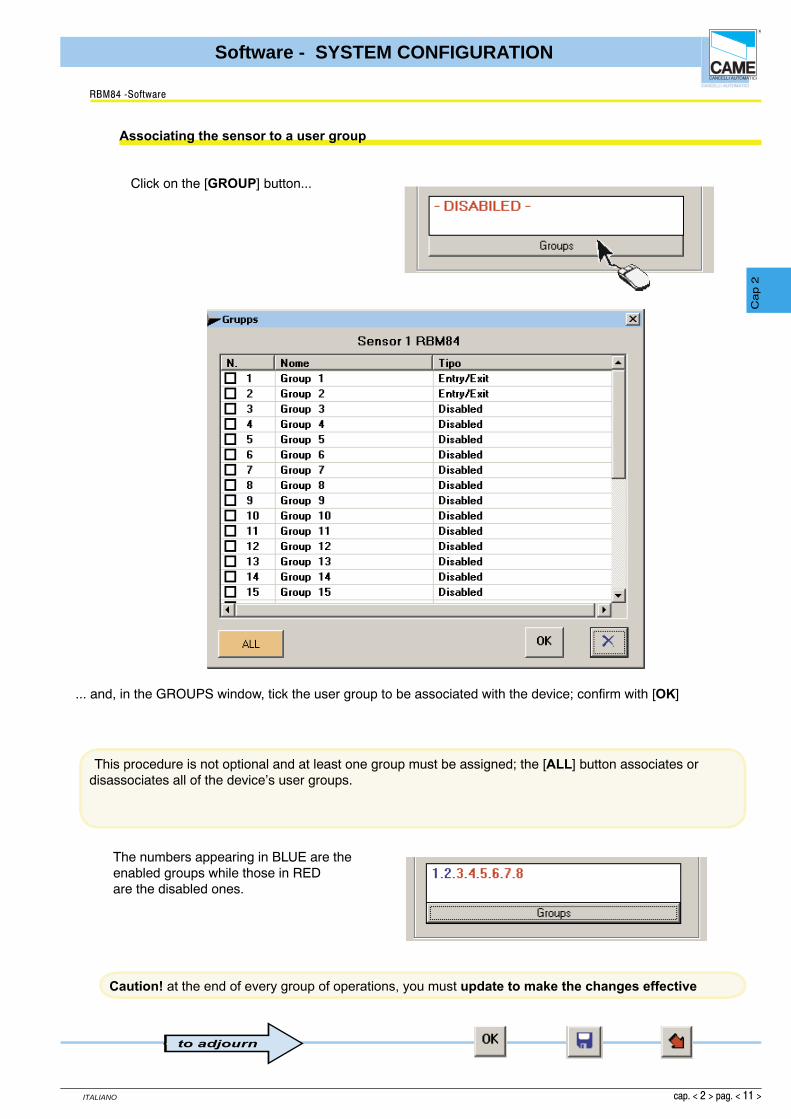
Click on the [GROUP] button...
... and, in the GROUPS window, tick the user group to be associated with the device; confirm with [OK]
RBM84 -Software
Associating the sensor to a user group
This procedure is not optional and at least one group must be assigned; the [ALL] button associates or disassociates all of the device’s user groups.
The numbers appearing in BLUE are theenabled groups while those in REDare the disabled ones.
to adjourn
Caution! at the end of every group of operations, you must update to make the changes effective

cap. < 2 > pag. < 12 >
ITALIANO
Software - SYSTEM CONFIGURATION
Cap 2
FUSE
630m
A
12
34
56
78
910
1112
0304
0506
07V1
V2V3
V4V5
CONTR
OL
BOARD
PSIO1
TRANSFORM ER TERM INAL B LOC K
LINE FUSE 5A
C AM EU2
REM REM PC 30
LT001 R501/2S5000S6000S7000
DIGITAL INPUT
1
2
3
4
TSP00LT001
S5000S6000S7000
TSP00 R501/2
NO CNC
O
A NO CNC NO CNC NO CNC NO CNC NO CNCNC NO C
O UT 1
A B GND NONC C
O UT 2
A B GNDL N
Select the output (1-8) and match it to oneof the names/devices appearing in the pull-down menu
In the OUTPUTS board,the outputs connected to RBM84 must be programmedwith the function type and any activation timeof the related relays;If there are no automations connected,select or leave “Disabled” assuggested in the menu.The output number correspondsexactly to the number labelled on the device connected to theterminal board; see figure
In the pull-down menu of the Local Outputs area there appear (by default) the traffi c light exits and the normal exitsas defi ned in Assign Exit NameThe exit device matching is independent of the physical connection of the latter on RBM84 or REM;
RBM84 -Software
Confi guring the outputs connected to RBM84
Activating the RBM84 outputs
1
2
1- Select the output (1-8)
2- And match it to one of the names/devices appearing in the pull-down menu

cap. < 2 > pag. < 13 >
ITALIANO
Software - SYSTEM CONFIGURATION
Cap 2
The monostable functionis proposed as default, therefore we may select the relay activation time by clicking on the scroll-down bar, which can vary between 1 second and 10 minutes.
If, instead, the bistable function is required,click on the related box
RBM84 -Software
Relay function
to adjourn
Caution! at the end of every group of operations, you must update to make the changes effective

cap. < 2 > pag. < 14 >
ITALIANO
Software - SYSTEM CONFIGURATION
Cap 2
For each entrance, select an output which this digital device will act on; the related box must also be ticked if the contact of the device is NC type (normally closed)
All the supplementary command and control devices must be programmed in the configuration dialogof the digital Entrances (INGR), (for instance safety buttons, sensitive footboards, alarms etc.) that will be connected to RBM84 andact on any of the RBM84 and REM outputsN.B. There are also functions other thanthe normal outputs-Block-Entry alarm-Reset alarm-Car-park entry-Car-park exit.
The digital entrance/exit association isindependent of the physical position of the exit on RBM84 or REM;
RBM84 -Software
Confi gure the digital entrances connected to RBM84
Associate the digital devices to the exits
1- Select the entrance to set
2- For each entrance, assign an outputor device which this digital apparatuswill act on.
3- Tick the related box if thedevice is NC type (normally closed)
1
2
3
to adjourn
Caution! at the end of every group of operations, you must update to make the changes effective

cap. < 2 > pag. < 15 >
ITALIANO
Software - SYSTEM CONFIGURATION
Cap 2
In the same way as with RBM84, the REMs configuration dialog must be used to program all the control devices, the exits and digital inputs connected to them; to move from one REM to the other, simply click on the yellow arrow or on the related icon in the system display window
The name typed here has only a recognition function and does not interact with the software.
RBM84 -Software
Confi guring the REMs
Assign a name to the REMs
A feature of the system display window is that if the REMsare green they are communicating, whereas if they are red they are not

cap. < 2 > pag. < 16 >
ITALIANO
Software - SYSTEM CONFIGURATION
Cap 2
CANCELLI AUTOMATICI
CONTROL BOARD
REM
1 2
C
2 1
A B A B
1 2
S5000/S6000/S7000
S1 GND S1 GND
1 2
TSP00/LT001
A B GND
1
REM
A B GND
2
REM
In the Type pull-down menu, select the type ofsensor connected:- S5000/S6000/S7000 keypad - remote controls of the TAM or ATOMO series - TSP00/LT001 transponder and confi rm with [OK]
In the Function pull-down menu, select the function of the connected sensor:- entry and exit- entry only- exit only- internal access and confirm with [OK]
In the Sensors area of the REM board n, the type, function and associations of both the control devices connected to the REM must be configured.The sensor number corresponds exactly to thesensor connected to the terminal board labelled withthe same number; see figure
RBM84 -Software
Confi gure the control sensors connected to the REMs
Sensor type (REM)
Function of the sensor (REM)

cap. < 2 > pag. < 17 >
ITALIANO
Software - SYSTEM CONFIGURATION
Cap 2
In the Car-park pull-down menu, selectthe association with a Traffic light
In the Association pull-down menu, select the device association with one of the connected exits and confi rm with [OK]
RBM84 -Software
Associating the sensor to an exit (REM)
Association of the sensor to a traffi c-light control (REM)
##Cost/Tariff Function (differentiated output) (REM)
1
2
To function correctly, the user must be with the current status set at IN, i.e. by making an accessinto the system or changing the status manually. (See Section 4, page 18)
1- To use the cost function, set thesensor as internal passage.
2- Set the value associated to the sensor,
to adjourn
Caution! at the end of every group of operations, you must update to make the changes effective

cap. < 2 > pag. < 18 >
ITALIANO
Software - SYSTEM CONFIGURATION
Cap 2
Click on the [GROUP] button...
... and, in the GROUPS window, tick the user group to associate the device with; then confirm with [OK]
This procedure is not optional and you must assign at least one group; the [ALL] button associates or dissociates all the user groups from the device.
RBM84 -Software
Associating the sensor to a user group (REM)
The numbers that appear written in BLUE are thegroups enabled, whereas those written in REDare the disabled ones
to adjourn
Caution! at the end of every group of operations, you must update to make the changes effective

cap. < 2 > pag. < 19 >
ITALIANO
Software - SYSTEM CONFIGURATION
Cap 2
REM
OUT1
NC NO C L2 L1
OUT2
NC NO C
Select the output and associate it to one of the names/devices appearing in the pull-down menu
In the Local Outputs area of the REM board, for both the outputs the function type mustbe programmed along with any interval of relay activation;If there are no automations connected, select or leave “Disabled” as supported by the menu.
In the pull-down menu of the Local Outputs area , appear as default the eight traffi c light outputs and the normal outputs defined in Assign Output Nameas well as an output called Alarm and one called Intrusion alarm;The exit device matching is independent of the physical connection of the latter on RBM84 or REM. The output number corresponds exactly to the device connected to the terminal board labelled with the same number; see figure
RBM84 -Software
Confi guring the REM outputs
Activating the REM outputs

cap. < 2 > pag. < 20 >
ITALIANO
Software - SYSTEM CONFIGURATION
Cap 2
The monostable function is default so we can select therelay activation time by clicking on thescroll-down bar
If instead you want the bistable function , click on the related box
The traffi c-light controlled exits are bistable only
RBM84 -Software
Relay function
to adjourn
Caution! at the end of every group of operations, you must update to make the changes effective

cap. < 2 > pag. < 21 >
ITALIANO
Software - SYSTEM CONFIGURATION
Cap 2
For each entrance, select an output that this supplementary digital devicewill act on; also the related box must be ticked if the device is type NC(normally closed)
In the inputs area of the REM n boardyou must program the supplementary command and control devices (e.g. safety buttons, sensitive footboards, alarms etc.) that will be connected to the REM and act on any one of the RBM84 and REM outputs.
In the pull-down menu, there appear, in addition to the normal exits defined in Assign Exit Name,exits/functions defined as “Block”, “Entry Alarm”, “Reset Alarm “ and “Entry” + “Exit” for each traffic-light control;The digital input/output association is independent of the physical position of the latter on RBM84 or REM;
RBM84 -Software
Confi guring the digital entrances of the REMs
Assign the digital devices to an output (REM)
to adjourn
Caution! at the end of every group of operations, you must update to make the changes effective

CONTENTSSUBJECT PAGE
Timings configuration window .................................................................................... 2
Tariffs configuration dialog ........................................................................................... 3
Prepaid Values ............................................................................................................ 3
Discount levels ........................................................................................................... 4
Configuration dialog-User Time Bands ...................................................................... 5
Configuration dialog-Blocked Days ............................................................................. 6
Configuration dialogPlanned Openings and Antipassback ......................................... 7
Configuration dialog-PlannedOpenings ..................................................................... 8
RBM84 - SOFTWARE
CONFIGURATIONTIMINGS
S E C T I O N 3

cap. < 3 > pag. < 2 >
ENGLISCH
Software - CONFIGURATION TIMINGS
Cap 3
Configuration window of the system timings
RBM 84 -Software
1 - Configurat ion dialog of tar i f fs, credits and discounts.
2 - Configurat ion dialog of t ime bands.
3 - Configurat ion dialog of blocked and free days.
4 - Configurat ion dialog of planned openings and t imed antipassback.
5 - Close button
6 - Button for reading RBM84 t imings
7 - Button for recording t imings on RBM84
8 - Button for saving to PC hard disk.
9 - Button for cancel l ing changes
10- OK button (confirm changes)
1 2 3 4
56710 9 8
cap. < 3 > pag. < 3 >
ENGLISCH
Software - CONFIGURATION TIMINGS
Cap 3
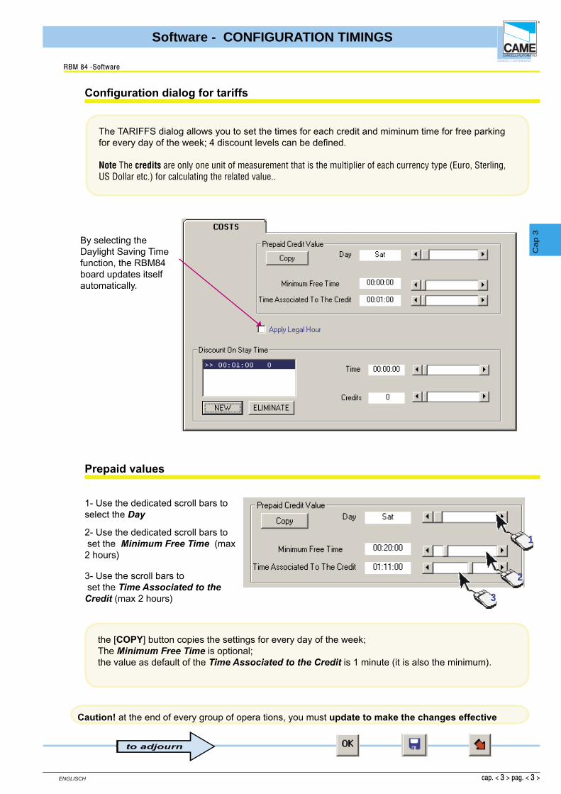
The TARIFFS dialog allows you to set the times for each credit and miminum time for free parking for every day of the week; 4 discount levels can be defi ned.
Note The credits are only one unit of measurement that is the multiplier of each currency type (Euro, Sterling, US Dollar etc.) for calculating the related value..
the [COPY] button copies the settings for every day of the week;The Minimum Free Time is optional;the value as default of the Time Associated to the Credit is 1 minute (it is also the minimum).
Confi guration dialog for tariffs
RBM 84 -Software
Prepaid values
1- Use the dedicated scroll bars to select the Day
2- Use the dedicated scroll bars to set the Minimum Free Time (max 2 hours)
3- Use the scroll bars to set the Time Associated to the Credit (max 2 hours)
1
2
3
By selecting the Daylight Saving Timefunction, the RBM84 board updates itselfautomatically.
to adjourn
Caution! at the end of every group of opera tions, you must update to make the changes effective

cap. < 3 > pag. < 4 >
ENGLISCH
Software - CONFIGURATION TIMINGS
Cap 3
set up to 4 discount levels, priced according to time and credits
In this illustration, 2 discount levels have been set; after the fi rst hour, the user has the right to 1discount credit; after the second hour, 3 discount credits. At any time, the discounts may be cancelled with the [CANCEL] button
Discount levels
RBM 84 -Software
1- click on the NEW key
1
2
3
2- set the time interval
3- set the creditsto be discounted
to adjourn
Caution! at the end of every group of opera tions, you must update to make the changes effective

cap. < 3 > pag. < 5 >
ENGLISCH
Software - CONFIGURATION TIMINGS
Cap 3
In the TIME BANDS dialog, up to 8 time bands may be set for every day of theweek with the relative prepaid value.
Note The default settings are: number of bands = 8; range of bands = 3 hours; prepaid value = 1 credit..
Confi guration dialog of user time bands
RBM 84 -Software
1- Select the day to set.
1
6
4
3
52
2- Select the time band to change.3- Set the time for the band to start from4- Set the time for the band to end at5- Assign a value to the band..
6- Select the band status:ENABLED: bothentry and exit are permitted;ENTRY: entry only is permittedBLOCKED: neitheraccess nor exitare permitted;EXIT; exit onlyis permitted.
the [COPY] button copies the settings for every day of the week;Note:The bands not used must be neutralised by selecting ‘blocked’.
to adjourn
Caution! at the end of every group of opera tions, you must update to make the changes effective
cap. < 3 > pag. < 6 >
ENGLISCH
Software - CONFIGURATION TIMINGS
Cap 3
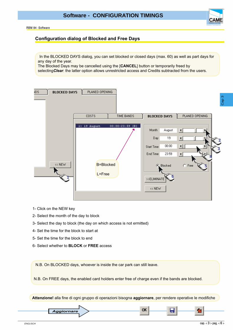
In the BLOCKED DAYS dialog, you can set blocked or closed days (max. 60) as well as part days for any day of the year.The Blocked Days may be cancelled using the [CANCEL] button or temporarily freed by selectingClear: the latter option allows unrestricted access and Credits subtracted from the users.
Confi guration dialog of Blocked and Free Days
RBM 84 -Software
1
2
3
4
5
6
1- Click on the NEW key
2- Select the month of the day to block
3- Select the day to block (the day on which access is not ermitted)
4- Set the time for the block to start at
5- Set the time for the block to end
6- Select whether to BLOCK or FREE access
Aggiornare
Attenzione! alla fi ne di ogni gruppo di operazioni bisogna aggiornare, per rendere operative le modifi che
N.B. On BLOCKED days, whoever is inside the car park can still leave.
N.B. On FREE days, the enabled card holders enter free of charge even if the bands are blocked.
B=Blocked
L=Free

cap. < 3 > pag. < 7 >
ENGLISCH
Software - CONFIGURATION TIMINGS
Cap 3
The planned openings, for instance at a production unit where staff mostly enter andleave in two waves per working day, allow an exit to be set for once or
twice during the day, after which the system reverts to its planned access functions.
Confi guration dialog of Planned Openings and Antipassback
RBM 84 -Software
Bar for setting the Antipassback time limit
1
1- Clicking on the PLANNED OPENINGS icon activates the confi guration window
CancelApply Changes
Close
Confi guration Rectangle
2 2- Click on the ‘new’ icon to display the confi guration rectangle.

cap. < 3 > pag. < 8 >
ENGLISCH
Software - CONFIGURATION TIMINGS
Cap 3
Confi guration dialog of the Planned Openings
RBM 84 -Software
3
3- Select the entrance to activate.
4
5
6
7
4- Set the opening time
5- Set the closing time
6- Select the days for it to open on
7- To ensure intervention takes place,this must be enabled.
To have a setting applied to every day, simply click on ‘All’.Next click on Apply Changes to update the newsettings..
Aggiornare
Attenzione! alla fi ne di ogni gruppo di operazioni bisogna aggiornare, per rendere operative le modifi che

CONTENTSsubject page
General notes ............................................................................................................ 2
Users’ configuration window .................................................................................. 3
Registering a new user ............................................................................................. 4
Saving the user code ................................................................................................ 6
Configurating ACCESS mode .................................................................................. 9
Normal access procedure ...................................................................................... 10
Prepaid access procedure...................................................................................... 11
Prepaid time-limit access procedure .................................................................... 13
Access validity ........................................................................................................ 14
Adding a given number of Users ........................................................................... 15
Users’ status check ................................................................................................ 18
RBM84 - SOFTWARE
CONFIGURATIONUSERS
S E C T I O N 4

cap. < 4 > pag. < 2 >
ENGLISCH
Software - CONFIGURATION USERS
Cap 4
During User-Confi guration operations, we recommend you frequently save the selections made as this will speed up the whole programming process (avoiding frequent checks and re-programming) and make it safer.
You can use
the [UPDATE] button,
the [SAVE USERS] button
and the graphic button [WRITE USER IN RBM84]
, which must be pressed in the order described.
In the following pages we will indicate at which points it is critical to save data, with the following symbol:
General notes
RBM 84 -Software
to adjourn

cap. < 4 > pag. < 3 >
ENGLISCH
Software - CONFIGURATION USERS
Cap 4
1 - Record dialog of the users’ personal data2 - Dialog for saving user codes 3 - Configuration dialog of access procedures for each user (times, tariffs, restrictions etc.)4 - Dialog for each user’s current situation 5 - Close button 6 - Read user from RBM84 button 7 - Write user to RBM84 button 8 - APB re-synchronisation button 9 - Save (on computer hard drive) button 10- Cancel button11- OK (apply changes made) button12- Field for searching User Name13- User list window 14- Create new user key (the 4 dialogs are empty without at least one registered user).
Users’ configuration window
RBM 84 -Software
5
1 2 3 4
678910
14
1112
13

cap. < 4 > pag. < 4 >
ENGLISCH
Software - CONFIGURATION USERS
Cap 4
Click on [NEW] and the fi elds for adding personal data etc. will appear
In the REGISTER dialog, the user’s personal data such as name, addressesand group may be recorded.The [NEW SEQUENCE] key is used to generate “x” number of users having the same settings(or command device: Keyboard, Remote Control or Card) as those of the last user generated
Registering a NEW USER
RBM 84 -Software

cap. < 4 > pag. < 5 >
ENGLISCH
Software - CONFIGURATION USERS
Cap 4
... key in the data required
... click on [GROUP] key] ...
... select the group you want to associate the user to; then click [OK]
It is compulsory to assign users to at least one User Group.It is essential, though, in systems where there are several entrances used for different user categories. A typical example is a company having entrances designated specifi cally to its offi ces, production units, suppliers, etc. and where some users (e.g. surveillance or maintenance personnel) must be allowed access through all of the entrances.
The registration date appears automatically while all other data are optional
The [ALL] button associates or disassociates the user to/from all the groups.The default selection isno association
Registering a NEW USER
RBM 84 -Software
cap. < 4 > pag. < 6 >
ENGLISCH
Software - CONFIGURATION USERS
Cap 4
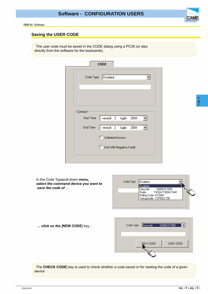
In the Code Typepull-down menu, select the command device you want to save the code of ...
The user code must be saved in the CODE dialog using a PC30 (or alsodirectly from the software for the keyboards).
... click on the [NEW CODE] key...
Saving the USER CODE
RBM 84 -Software
The CHECK CODE] key is used to check whether a code saved or for reading the code of a given device

cap. < 4 > pag. < 7 >
ENGLISCH
Software - CONFIGURATION USERS
Cap 4
... and then, within 10 seconds,
D- type the number code into the dedicated keypad on the front panel of PC30 and then type “E”"
A- for the TAM and ATOMO remote controls, press the key to save, sending the signal to the dedicated area on the front panel of PC30, or
B - for TSP00, move the proximity Card you want to save to the dedicated area on the front panel of PC30, or
C- for LT001, swipe the Card to save along the dedicated groove on thefront panel of PC30.
The code-saving functions described above (A- sending the signal,B- bringing the Card in proximity to the panel, C- swiping the Card or D- typing the code) must take place within the time it takes (10”) for the graduated bar in the lower part of the main window to scroll
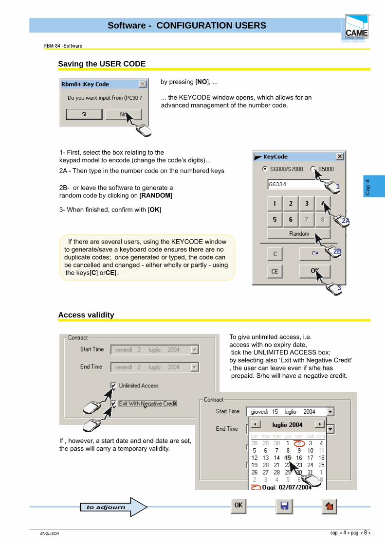
For the S5000, S6000 and S7000 keyboards however, we are promted to indicate if we want to use PC30 to save the code; if not, saving must be made by the software (see next page)
... by pressing [YES],
Saving the USER CODE
RBM 84 -Software
cap. < 4 > pag. < 8 >
ENGLISCH
Software - CONFIGURATION USERS
Cap 4
by pressing [NO], ...
If there are several users, using the KEYCODE window to generate/save a keyboard code ensures there are no duplicate codes; once generated or typed, the code can be cancelled and changed - either wholly or partly - using the keys[C] orCE]..
Saving the USER CODE
RBM 84 -Software
1
1- First, select the box relating to thekeypad model to encode (change the code’s digits)...
... the KEYCODE window opens, which allows for an advanced management of the number code.
2A - Then type in the number code on the numbered keys
2B- or leave the software to generate arandom code by clicking on [RANDOM]
3- When fi nished, confi rm with [OK]
2A
2B
3
Access validity
To give unlimited access, i.e.access with no expiry date, tick the UNLIMITED ACCESS box; by selecting also ‘Exit with Negative Credit’, the user can leave even if s/he has prepaid. S/he will have a negative credit.
If , however, a start date and end date are set, the pass will carry a temporary validity.
to adjourn
cap. < 4 > pag. < 9 >
ENGLISCH
Software - CONFIGURATION USERS
Cap 4
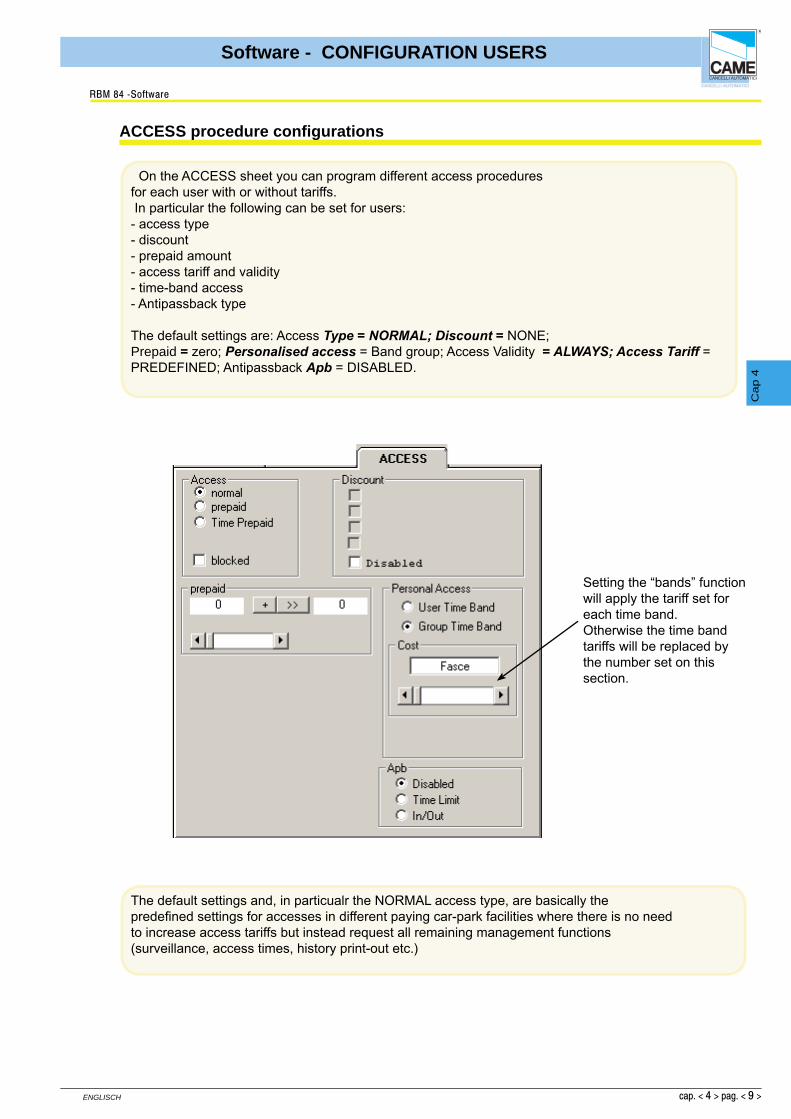
On the ACCESS sheet you can program different access proceduresfor each user with or without tariffs. In particular the following can be set for users:- access type- discount- prepaid amount- access tariff and validity- time-band access- Antipassback type
The default settings are: Access Type = NORMAL; Discount = NONE;Prepaid = zero; Personalised access = Band group; Access Validity = ALWAYS; Access Tariff = PREDEFINED; Antipassback Apb = DISABLED.
The default settings and, in particualr the NORMAL access type, are basically thepredefi ned settings for accesses in different paying car-park facilities where there is no needto increase access tariffs but instead request all remaining management functions (surveillance, access times, history print-out etc.)
ACCESS procedure configurations
RBM 84 -Software
Setting the “bands” function will apply the tariff set for each time band.Otherwise the time band tariffs will be replaced bythe number set on this section.

cap. < 4 > pag. < 10 >
ENGLISCH
Software - CONFIGURATION USERS
Cap 4
Select the required access bands, for every day of theweek
Select the type of AntiPassBack (not compulsory)
The AntiPassBack is used to stop the fraudulent use of the access devices, for example by allowing more than one vehicle to enter or persons with only one Radio-control or Card.
AntiPassBack Time limit means that the user, after passing the entrance, cannot pass back again across the entrance way for all the time of the antipassback defi ned in Timings > Time bands
AntiPassBack In/Out means that the user, after passing through the entrance, can only enter again after having left through the normal exit.
By leaving the default access as NORMAL, the Discount andPrepaid areas are omitted.
The [ALL] button enables or disables all of the time bands.If the time band appears red, this means it is blocked (for all users) in Timings > Time BandsA disabled time band hinders access; if the user is alreadyinside, the subtracted credits (as set in the following pages) will be counted only for the PREPAID and PREPAID WITH TIME LIMIT procedures
NORMAL access procedure
RBM 84 -Software
for every dayof the week
to adjourn
Antipassback
The bands change colour according to the settings:<> Black= entry/exit function Red= Band Blocked<< Blue= exit-only function >> Brown= entry-only function
to adjourn

cap. < 4 > pag. < 11 >
ENGLISCH
Software - CONFIGURATION USERS
Cap 4Set the user-purchased Credits, which will appear in the left-
hand box, ...
By selecting PREPAID access, it is essential to defi ne the Prepaid area, whereas all the other areas are optional (see Normal Access and Personalised Access for the access validity)The term “Prepaid” means a number of credits purchased by the user having a value defi ned individually by each system manager (for example 1.20 Euro/dollar/pounds sterling/etc. for each credit): RBM84 does not calculate in currency terms, but only in number of credits.
... and transfer them into the right-hand box with the button [>>]
If, before “spending” all the credits, the user buys some more, to add them, click on the button [+]
The right-hand box instead represents the availability of Credits the user still has (i.e. after already subtracting the already-”spent” ones).
The left-hand box always represents the last purchase of Credits by the user.
PREPAID access procedure
RBM 84 -Software
to adjourn
cap. < 4 > pag. < 12 >
ENGLISCH
Software - CONFIGURATION USERS
Cap 4
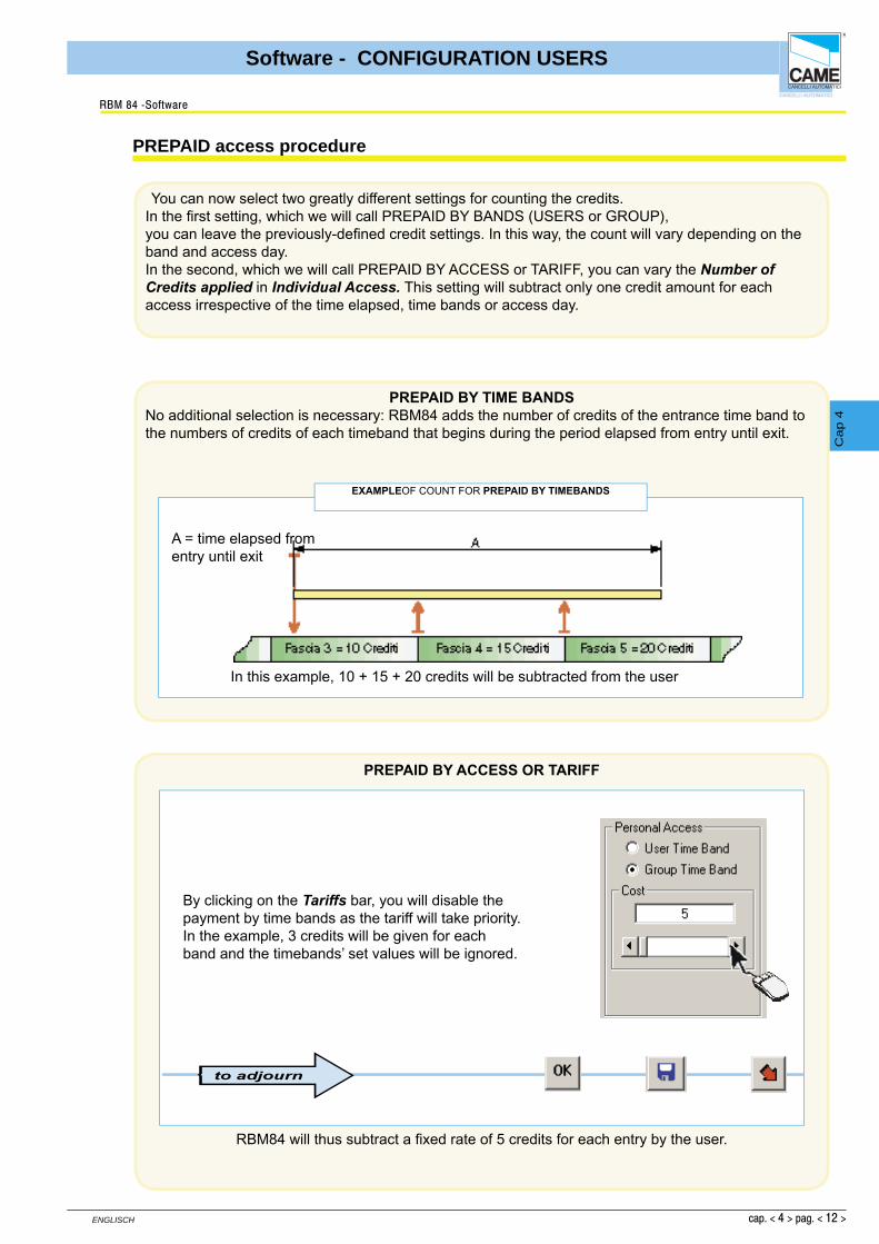
You can now select two greatly different settings for counting the credits.In the fi rst setting, which we will call PREPAID BY BANDS (USERS or GROUP),you can leave the previously-defi ned credit settings. In this way, the count will vary depending on the band and access day.In the second, which we will call PREPAID BY ACCESS or TARIFF, you can vary the Number of Credits applied in Individual Access. This setting will subtract only one credit amount for each access irrespective of the time elapsed, time bands or access day.
PREPAID BY TIME BANDSNo additional selection is necessary: RBM84 adds the number of credits of the entrance time band to the numbers of credits of each timeband that begins during the period elapsed from entry until exit.
EXAMPLEOF COUNT FOR PREPAID BY TIMEBANDS
In this example, 10 + 15 + 20 credits will be subtracted from the user
A = time elapsed from entry until exit
PREPAID access procedure
RBM 84 -Software
PREPAID BY ACCESS OR TARIFF
RBM84 will thus subtract a fi xed rate of 5 credits for each entry by the user.
By clicking on the Tariffs bar, you will disable thepayment by time bands as the tariff will take priority.In the example, 3 credits will be given for eachband and the timebands’ set values will be ignored.
to adjourn

cap. < 4 > pag. < 13 >
ENGLISCH
Software - CONFIGURATION USERS
Cap 4
With the PREPAID WITH TIME LIMIT mode, RBM84 multiplies the number of credits set in Individual Access, for each time interval associated to the credit, or fraction thereof, elapsing from entrance until exit..
The PREPAID WITH TIME LIMITmode is similar to the PREPAID mode and the areas to defi ne are the same (which we refer to you for the selection details).
The only difference is the way of calculating the credits to charge the user which, in this access type, is connected to a time interval (Time associated to the Credit,not to be confused with time band).
CALCULATION EXAMPLE FOR PREPAID WITH TIME
in this case, 4 time intervals will be subtracted (no. credits applied) from the user.
A = time elapsed from entry until exitB = time associated to theCredit
PREPAID WITH TIME-LIMIT access procedure
RBM 84 -Software
Click on the Tariffs bar to set the numberof credits.
This procedure takes account of the set-up madein the “tariffs” window: time associated to credit.
to adjourn

cap. < 4 > pag. < 14 >
ENGLISCH
Software - CONFIGURATION USERS
Cap 4
In the CODES dialog, for all the three modes, you can also set an access validity time (subscription type) irrespective of the credits purchased or remaining; this validity can be renewed at any time.
Access validity
RBM 84 -Software
1
1- Set the contract start date
2
2- Set the contract end date
With UNLIMITED ACCESS, there is no longer acontract expiry date. Instead, with EXIT WITH NEGATIVE CREDIT the user can exit even if he/she has fi nished the credits in his/her pass (otherwise the user would not be able to leave), and at the next recharge, the amount owed will be signalled in red.
The code validity (discount ticket) ends at 24:00on the day set
to adjourn

cap. < 4 > pag. < 15 >
ENGLISCH
Software - CONFIGURATION USERS
Cap 4
This procedure adds any number of users (up to the maximum number allowed by the system) with the same characteristics of code type (Keyboard, Radio-control or Card), access type and group belonging. It is therefore necessary to confi gure a user with the desired characteristics, through the PERSONALISED, CODE and ACCESS dialogs, so as to then return to PERSONALISED and start up the procedure.
Click on [NEW(it is not necessary to complete the data in this phase) ...
... go to the CODE dialog and save a user code type ...
... go to the ACCESS dialog and save an access type ...
... then click on the [NEW SEQUENCE] button ...
If a new user is not saved, the procedure will repeat the last user entered (in the exampleuser 007), applying the same sensor type characteristics.
Adding a GIVEN NUMBER OF USERS (New Sequence)
RBM 84 -Software
2 3
1 4
to adjourn

cap. < 4 > pag. < 16 >
ENGLISCH
Software - CONFIGURATION USERS
Cap 4
select the number of users to add (10 users as default) and run the procedure with the [START] button.
... the software will add them to the user list, generating a different random code for each one; click the[END] button to terminate the procedure.
At this point, if the code type is a Keyboard ...
Adding a GIVEN NUMBER OF USERS
RBM 84 -Software
1
2 3
to adjourn

cap. < 4 > pag. < 17 >
ENGLISCH
Software - CONFIGURATION USERS
Cap 4
... you must click [START] again and save a valid code. Click the [END]button to terminate the procedure.
... if the code type is instead a Transmitter or a Card:
...... after starting up the procedure ...
... you must save, through PC30, the respective code for each device
... if the code being saved is already present
For each generation of new user, the graduated bar starts again while waiting for the next code.
This also applies when, for whatever reason, you don’t succeed in saving it within 10 seconds
Adding a GIVEN NUMBER OF USERS
RBM 84 -Software
Created !
to adjourn

cap. < 4 > pag. < 18 >
ENGLISCH
Software - CONFIGURATION USERS
Cap 4
The STATUS dialog gives the updated status of every user with reference to:- the date and time of the last entry- the date and time of the last exit- the presence or absence of the user within the system- the total length of stay within the system- the total number of accesses made- The number of remaining Credits
Change the Current User Status
Zeros the Total Length of Stay counter
Zeros the Total Number of Accesses counter
The Current Status (wheter present in the system) can be changed at any time and the Total Length of Stay and Total Visits can also be zeroed using the relevant buttons
USER STATUS check
RBM 84 -Software

CONTENTSsubject page
RBM84 Upgrades ...................................................................................................... 2
Display preferences .................................................................................................. 3
History Management .................................................................................................. 3
Events history ............................................................................................................ 4
Daily Management .................................................................................................... 6
RBM84 - SOFTWARE
UPDATES - DAILY HISTORY
S E C T I O N 5

cap. < 5 > pag. < 2 >
ENGLISCH
Software - UPDATES - DAILY HISTORY
Cap 5
Tick the section to update and click on [UPDATE], then[YES] to confi rm the update
... and wait for the graduated barin the lower part of the main window to scroll down; then click on the [END]button
RBM84 Upgrades
RBM 84 -Software
The UPDATES dialog is used to update, simultaneously or individually, the three key sections of the confi guration: System, Timings and Users.
Before starting up the update procedures, all the changes madepreviously must be saved; to this end, we recommend pressing the buttons shown here, at least at the end of every confi guration section indicated above.
to adjourn
1
2 3
4
5

cap. < 5 > pag. < 3 >
ENGLISCH
Software - UPDATES - DAILY HISTORY
Cap 5
History Management
RBM 84 -Software
Clicking this button opens the “History” window.
1
2
3
4
5
13
12
1110
9 8 61 - Event numbering column
2 - Event description column
3 - User display column
4 - Display column of the gate or sensor
involved in the event
5 - Event date and time column
6 - “Close” button
7 - “Export in EXCEL format” button.
8 - “Print” button.
9 - “New Search” button
10 - Box for selecting users to search
11 - Box for selecting the events to search
12 - Box for selecting interval end to search
13 - Box for selecting interval start to search
7
Display preferences
By selecting HISTORY USING SENSOR NAME orHISTORY USING GATE NAME, we can change the display of column4 and, if shown, select either the gate name where the event happens or the sensor name.
Instead, by selecting DISABLE ASSEMBLY ERROR , the assembly error is not managed.

cap. < 5 > pag. < 4 >
ENGLISCH
Software - UPDATES - DAILY HISTORY
Cap 5
User entry means registered persons’ access USER ENTRY
User exit means registered persons’ exitUSER EXIT
With Passage, a passage is notifi ed within the system, withoutchanging the APB status.
INTERNAL PASSAGE
With Internal Passage Error, a passage on the internalsensor is notifi ed without fi rst being entered in the system.
ERROR: PASSAGEINTERNAL
Unknown user means an attempted access of by someone not registeredin the system
UNKNOWN USER
If there is not at least one user group assigned, it will be impossibleto perform access
USER WITHOUTASSEMBLY
If during system-programming we forget to assign at least one group to each sensor, the sensor will not function
SENSOR WITHOUTASSEMBLY
Attempted access on blocked day.BLOCKED DAY
Attempted access with antipassback activated (the user still results as being within the system)
APB I/O
Attempted access outside the contract times (expired pass).CONTRACT EXPIRED
Attempted access with red traffi c light and related absence of places.RED TRAFFIC LIGHT
Attempted access with group not enabled to given sensor (or area)WRONG GROUP
Attempted access user disabled from operatingUSER ACCESS DISABLED
Attempted user access in time band not enabled ERROR ON TIME BAND
Attempted user access during entry time band not enabled ERROR ON ENTRY TIME BAND
History (EVENTS)
RBM 84 -Software
Attempted user access during time band not enabled at the exit ERROR ON EXIT TIME BAND
Attempted access with antipassback, time limit still active (time period not yet expired)
ERROR ON APB TIME
Attempted exit with insuffi cient credit (if not enabled at the exitwith negative credit)
INSUFFICIENT CREDIT
Access openings by PCACTIVATIONMANUAL ENTRY
Access openings through time programming ACTIVATIONTIME
Access closure through time programming(end of the planned opening)END ACTIVATIONTIME
System block by pushbutton that acts directly on RBM84or on REM unit
BLOCKLOCAL
Manual clearing of blocked system by external button.END BLOCK

cap. < 5 > pag. < 5 >
ENGLISCH
Software - UPDATES - DAILY HISTORY
Cap 5
History (EVENTS)
RBM 84 -Software
System block by the software.REMOTE BLOCK
Alarm activated by external pushbutton.MANUAL ALARM
Alarm shut-down activated by pushbutton.MANUAL ALARM RESET
This signals when a setting change is madeto the system (only visible if the Password has been inserted)
CHANGE SYSTEM
This signals when a change to the system access procedures is made (only visible if the Password has been inserted)
CHANGE ACCESS
This signals when a change to the managementof the passholders is made (only visible if the Password has been inserted)
CHANGE PASSHOLDERS
This item signals activation of the RBM84 board’s internal passwordBOARD PASSWORD ACTIVATION
This item signals activation of the RBM84 board’s internal passwordREMOVALPASSWORD BOARD
With this, it is worth noting the end of the connection by modem onRBM84
BEGIN COMMUNICATIONMODEM
Con questa voce si segnala la fi ne della connessione mediante modem su RBM84
END COMMUNICATIONMODEM
By selecting between the EVENTS and USERS we can fi ne-tune the search to reduce superfl uous data, thus allowing the relevant information to be found..
System unblock/release by software.REMOTE UNBLOCK

cap. < 5 > pag. < 6 >
ENGLISCH
Software - UPDATES - DAILY HISTORY
Cap 5
Daily Management
RBM 84 -Software
Clicking this button opens the “Daily History” window.
1
2
3
4
5
11
10 9
8 7 6
1 - Column of event numbering
2 - Column of event description.
3 - Acting carrier display column
4 - Column for displaying the gate involved
in the event
5 - Column with the event’s date and time.
6 - “ Close” button
7 - “Print” button
8 - “New Search” button
9 - Box for selecting the users to search
10 - Box for selecting the events to search
11 - Box for selecting the data to search
12 - “Export”button
The EVENTS and USERS items are the same as those described on pages 4 and 5.
12

CONTENTSsubject pag
Print window .............................................................................................................. 2
Print preview window................................................................................................... 3
Print preview window................................................................................................... 4
Project ManagementWindow ..................................................................................... 4
RBM84 - SOFTWARE
PRINTS
S E C T I O N 6
capitolo < 6 > pagina < 2 >
ITALIANO
Software - STAMPE
Cap 6
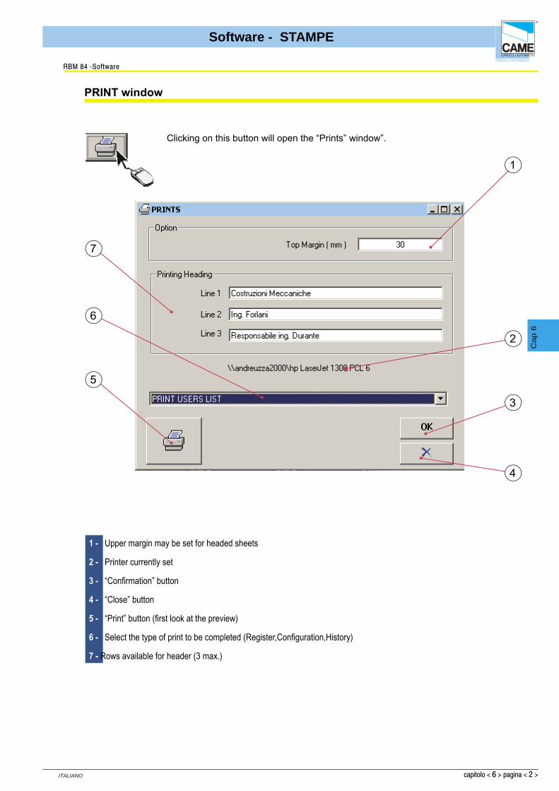
PRINT window
RBM 84 -Software
1 - Upper margin may be set for headed sheets
2 - Printer currently set
3 - “Confi rmation” button
4 - “Close” button
5 - “Print” button (fi rst look at the preview)
6 - Select the type of print to be completed (Register,Confi guration,History)
7 - Rows available for header (3 max.)
1
7
5
2
3
4
Clicking on this button will open the “Prints” window”.
6
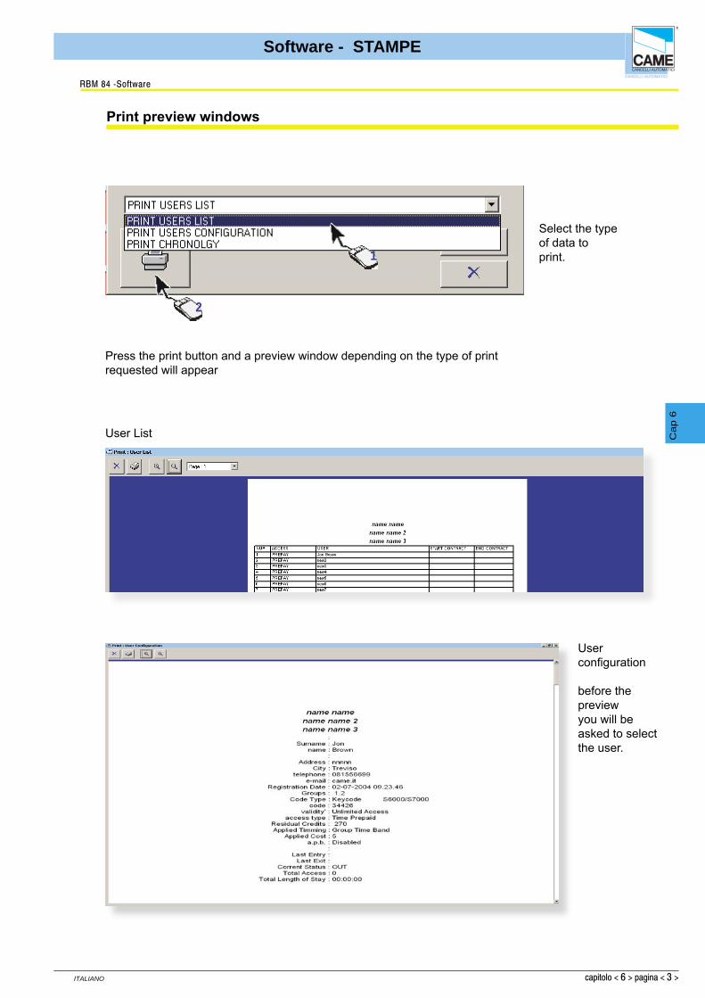
capitolo < 6 > pagina < 3 >
ITALIANO
Software - STAMPE
Cap 6
Print preview windows
RBM 84 -Software
Select the typeof data toprint. 1
2
Press the print button and a preview window depending on the type of print requested will appear
User List
User confi guration
before the previewyou will beasked to selectthe user.

capitolo < 6 > pagina < 4 >
ITALIANO
Software - STAMPE
Cap 6
RBM 84 -Software
Print Preview Windows
HistoryThe history before the preview will request the period of interest, and the type of action.
Project Management
Clicking on this button will open the Project Management window that allows different system confi gurations to be saved and loaded
Name of system currently in use.
Path - where to fi nd the fi le.
If more than one project is present, select which one to leave for the next start up
Various saved projects can be displayed
Save As button for current project
Button for removing saved projects.

CONTENTSsubject page
Adding the master password .................................................................................... 2
Changing the master password ................................................................................. 2
Adding the board password......................................................................................... 3
Access to password-protected board ......................................................................... 4
Adding users password .............................................................................................. 5
RBM84 - SOFTWARE
PASSWORD
S E C T I O N 7
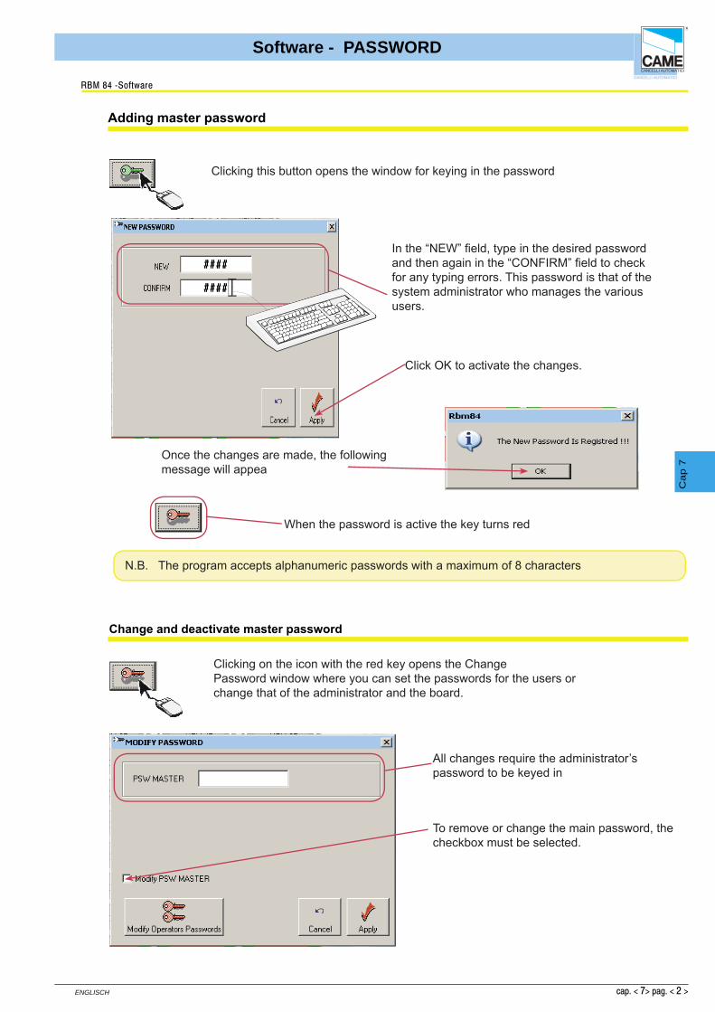
cap. < 7> pag. < 2 >
ENGLISCH
Software - PASSWORD
Cap 7
Adding master password
RBM 84 -Software
Change and deactivate master password
Clicking this button opens the window for keying in the password
In the “NEW” fi eld, type in the desired password and then again in the “CONFIRM” fi eld to check for any typing errors. This password is that of the system administrator who manages the various users.
Click OK to activate the changes.
Once the changes are made, the following message will appea
When the password is active the key turns red
N.B. The program accepts alphanumeric passwords with a maximum of 8 characters
Clicking on the icon with the red key opens the ChangePassword window where you can set the passwords for the users orchange that of the administrator and the board.
All changes require the administrator’s password to be keyed in
To remove or change the main password, the checkbox must be selected.
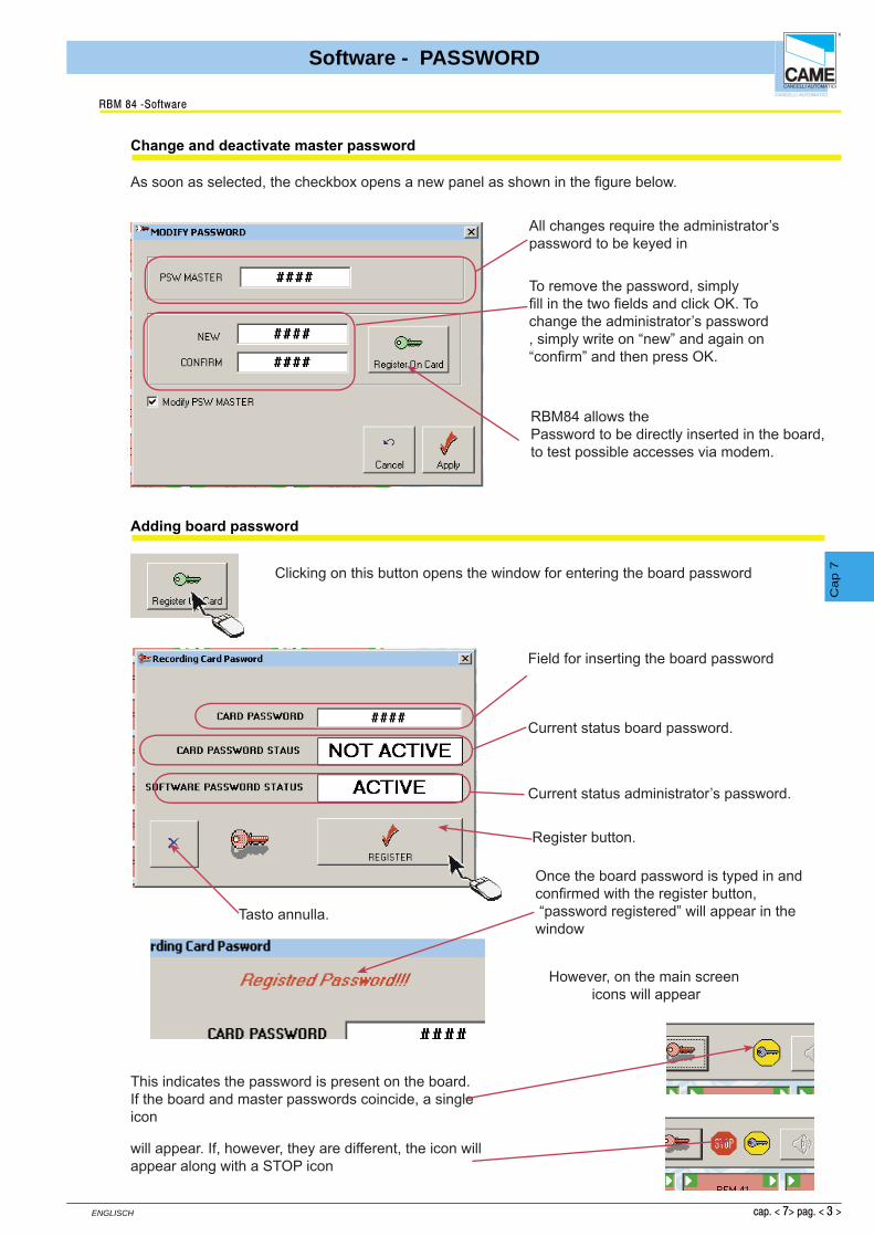
cap. < 7> pag. < 3 >
ENGLISCH
Software - PASSWORD
Cap 7
RBM 84 -Software
Change and deactivate master password
All changes require the administrator’s password to be keyed in
To remove the password, simply fi ll in the two fi elds and click OK. Tochange the administrator’s password, simply write on “new” and again on“confi rm” and then press OK.
As soon as selected, the checkbox opens a new panel as shown in the fi gure below.
RBM84 allows thePassword to be directly inserted in the board, to test possible accesses via modem.
Field for inserting the board password
Current status board password.
Current status administrator’s password.
Tasto annulla.
Register button.
Clicking on this button opens the window for entering the board password
Adding board password
Once the board password is typed in andconfi rmed with the register button, “password registered” will appear in the window
However, on the main screen icons will appear
This indicates the password is present on the board.If the board and master passwords coincide, a single icon
will appear. If, however, they are different, the icon will appear along with a STOP icon

cap. < 7> pag. < 4 >
ENGLISCH
Software - PASSWORD
Cap 7
RBM 84 -Software
Access to password-protected board
Clicking on this button opens the window for entering the board protection password (when already activated)
This operation allows connection of a password-protected RBM84, toa PC with software which has no password, or one different to that of the board.
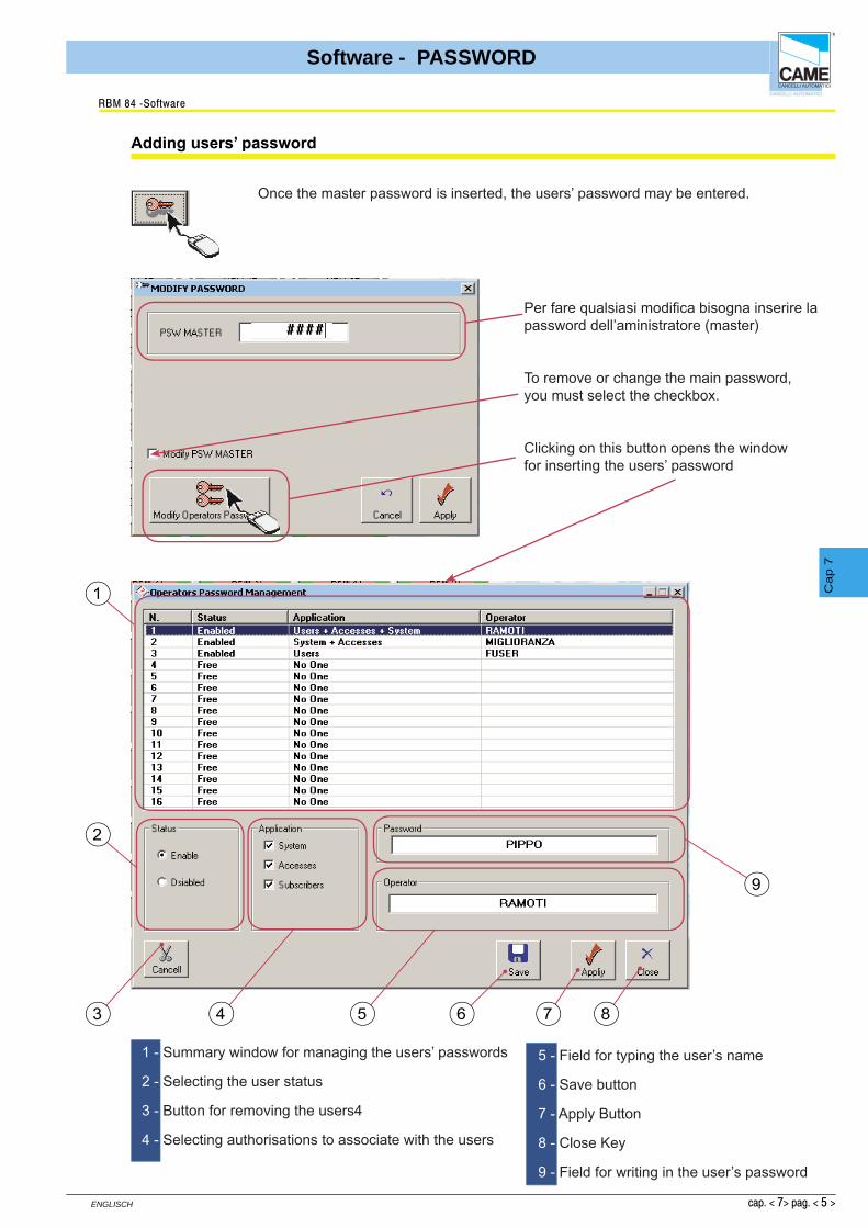
cap. < 7> pag. < 5 >
ENGLISCH
Software - PASSWORD
Cap 7
Adding users’ password
RBM 84 -Software
Once the master password is inserted, the users’ password may be entered.
Per fare qualsiasi modifi ca bisogna inserire lapassword dell’aministratore (master)
To remove or change the main password, you must select the checkbox.
Clicking on this button opens the window for inserting the users’ password
1
2
3 4 5 6 7 8
9
1 - Summary window for managing the users’ passwords
2 - Selecting the user status
3 - Button for removing the users4
4 - Selecting authorisations to associate with the users
5 - Field for typing the user’s name
6 - Save button
7 - Apply Button
8 - Close Key
9 - Field for writing in the user’s password
CONTENTSsubject page
Modem connection ..................................................................................................... 2
Connection with remote computer .............................................................................. 3Remote connection window ....................................................................................... 4
RBM84 - SOFTWARE
MODEM
S E C T I O N 8
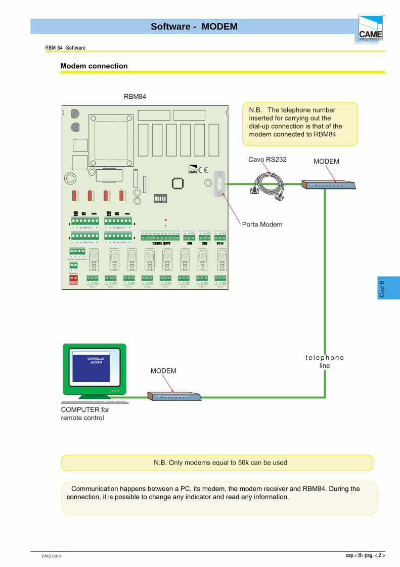
cap.< 8> pag. < 2 >
ENGLISCH
Software - MODEM
Cap 8
Modem connection
RBM 84 -Software
N.B. The telephone number inserted for carrying out thedial-up connection is that of the modem connected to RBM84
FUSE
630m
A
12
34
56
78
910
1112
0304
0506
07V1
V2V3
V4V5
CONTR
OL
BOARD
PSIO1
TRANSFORM ER TERM INAL B LOC K
LINE FUSE 5A
C AM EU2
REM REM PC 30
LT001 R501/2S5000S6000S7000
DIGITAL INPUT
1
2
3
4
TSP00LT001
S5000S6000S7000
TSP00 R501/2
BATTERYCHARGER BN1
A B C D
BATTERY
R700-R800
1
R700-R800
2
R700-R800
3
R700-R800
4
R70
0-
R80
0
1
R70
0-
R80
0
2
R70
0-
R80
0
3
R70
0-
R80
0
4
MODEM
MODEM
A B S1GNDOUT
NO CNC
O UT 3
A B GND NO CNC
O UT 4
A B GND NO CNC
O UT 5
A B GND NO CNC
O UT 6
A B GND NO CNC
O UT 7
A B GND NO CNC
O UT 8
A B GNDNC NO C
O UT 1
A B GND NONC C
O UT 2
A B GND
2 1345
ON
L NL N
P1 P2 P3 P4Com ComP5 P6 P7 P8 A B GNDA B GNDA B GND
A B S1GNDOUT
A B S1GNDOUTA B S1GNDOUT
RBM 8 Software
CONTROLLOACCESSI
Cavo RS232
RBM84
MODEM
MODEM
COMPUTER for remote control
t e l e p h o n e line
N.B. Only modems equal to 56k can be used
Porta Modem
Communication happens between a PC, its modem, the modem receiver and RBM84. During theconnection, it is possible to change any indicator and read any information.

cap.< 8> pag. < 3 >
ENGLISCH
Software - MODEM
Cap 8
Remote computer connection
RBM 84 -Software
1
2
3
4
1- Enter in confi guration PC 30
2-to select the modem
3-confi rm
4-activate the remote connection window
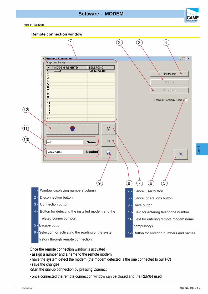
cap.< 8> pag. < 4 >
ENGLISCH
Software - MODEM
Cap 8
Remote connection window
RBM 84 -Software
Once the remote connection window is activated- assign a number and a name to the remote modem- have the system detect the modem (the modem detected is the one connected to our PC)- save the changes-Start the dial-up connection by pressing Connect- once connected the remote connection window can be closed and the RBM84 used
1 432
6 5789
10
11
12
1 - Window displaying numbers column
2 - Disconnection button
3 - Connection button
4 - Button for detecting the installed modem and the
related connection port.
5 - Escape button
6 - Selection for activating the reading of the system
history through remote connection.
7 - Cancel user button
8 - Cancel operations button
9 - Save button
10- Field for entering telephone number
11- Field for entering remote modem name
(compulsory)
12- Button for entering numbers and names