Runway excursion after leakage in hydraulic system€¦ · · 2016-12-19the memory item to turn...
32
DUTCH SAFETY BOARD Runway excursion after leakage in hydraulic system
Transcript of Runway excursion after leakage in hydraulic system€¦ · · 2016-12-19the memory item to turn...

DUTCHSAFETY BOARD
Runway excursion after leakage in hydraulic system
The Hague, December 2016
The reports issued by the Dutch Safety Board are open to the public.
All reports are also available on the Safety Board’s website www.safetyboard.nl
Photo cover: Rotterdam The Hague Airport
Runway excursion after leakage in hydraulic system30 September 2015
- 3 -
Dutch Safety Board
When accidents or disasters happen, the Dutch Safety Board investigates how it was possible for them to occur, with the aim of learning lessons for the future and, ultimately, improving safety in the Netherlands. The Safety Board is independent and is free to decide which incidents to investigate. In particular, it focuses on situations in which people’s personal safety is dependent on third parties, such as the government or companies. In certain cases the Board is under an obligation to carry out an investigation. Its investigations do not address issues of blame or liability.
Dutch Safety BoardChairman: T.H.J. Joustra
E.R. MullerM.B.A. van Asselt
Secretary Director: C.A.J.F. Verheij
Visiting address: Anna van Saksenlaan 502593 HT The Hague The Netherlands
Postal address: PO Box 954042509 CK The Hague The Netherlands
Telephone: +31 (0)70 333 7000 Fax: +31 (0)70 333 7077
Website: www.safetyboard.nl
NB: This report is published in the Dutch and English languages. If there is a difference in interpretation between the Dutch and English versions, the English text will prevail.

- 4 -
CONTENT
Abbreviations ������������������������������������������������������������������������������������������������������������� 5
General overview ������������������������������������������������������������������������������������������������������� 6
Summary �������������������������������������������������������������������������������������������������������������������� 7
Factual information ���������������������������������������������������������������������������������������������������� 8
Analysis ���������������������������������������������������������������������������������������������������������������������18
Conclusions, measures and actions ���������������������������������������������������������������������������21
Recommendations ���������������������������������������������������������������������������������������������������� 23
Appendix A� ������������������������������������������������������������������������������������������������������������ 24
Appendix B� �������������������������������������������������������������������������������������������������������������26
Appendix C� ������������������������������������������������������������������������������������������������������������ 28
Appendix D� ������������������������������������������������������������������������������������������������������������ 30

- 5 -
ABBREVIATIONS
AGL Above Ground LevelAOM Aircraft Operations ManualATPL Airline Transport Pilot Licence
CPL Commercial Pilot Licence
EASA European Aviation Safety Agency
HYDR Hydraulics
OM Operations Manual
UTC Co-ordinated Universal Time
- 6 -
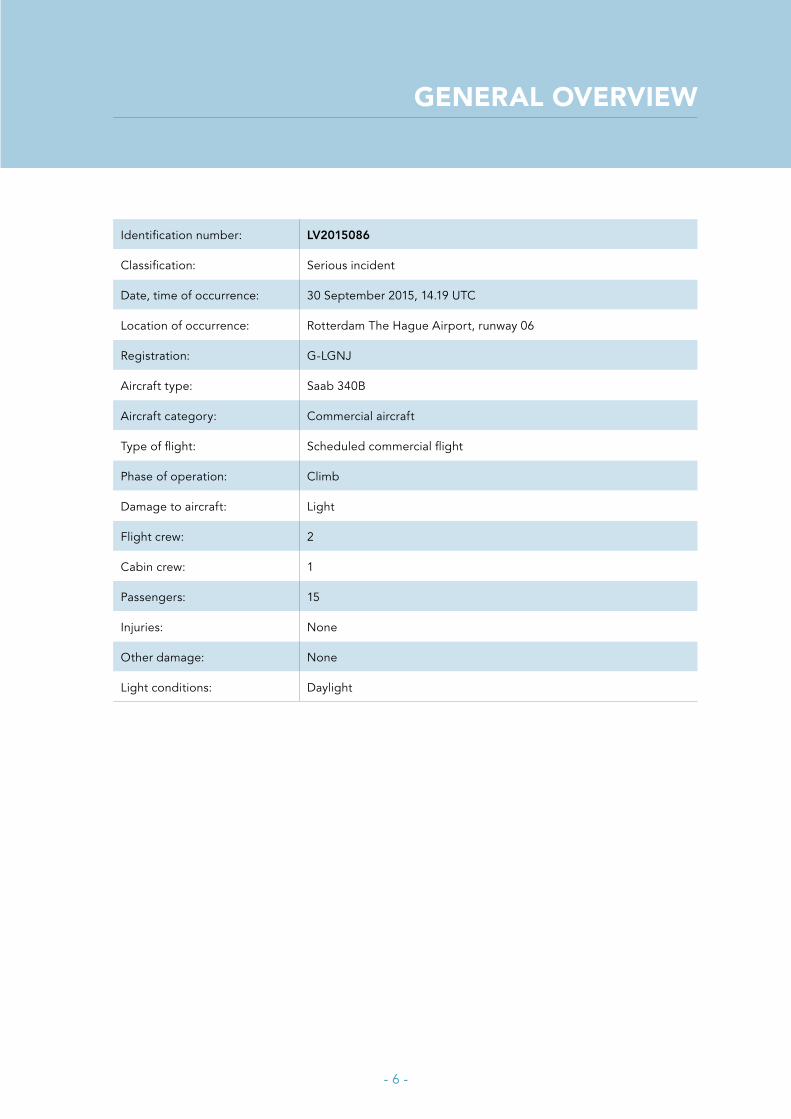
GENERAL OVERVIEW
Identification number: LV2015086
Classification: Serious incident
Date, time of occurrence: 30 September 2015, 14.19 UTC
Location of occurrence: Rotterdam The Hague Airport, runway 06
Registration: G-LGNJ
Aircraft type: Saab 340B
Aircraft category: Commercial aircraft
Type of flight: Scheduled commercial flight
Phase of operation: Climb
Damage to aircraft: Light
Flight crew: 2
Cabin crew: 1
Passengers: 15
Injuries: None
Other damage: None
Light conditions: Daylight

- 7 -
SUMMARY
Shortly after take-off from Rotterdam The Hague Airport to Aberdeen International Airport a Saab 340B with fifteen passengers, two flight crew and one cabin crew on board experienced a main hydraulic system failure on 30 September 2015. The aircraft returned to the airport of departure after having flown for a while in the nearby holding for trouble shooting. A safe landing was executed and the aircraft came to a stop on the runway, but during the engine shutdown the aircraft moved forward and to the left. The aircraft came to a full stop into the grass of the runway’s left hand shoulder. An emergency evacuation of the passengers followed. The passengers were uninjured.
The investigation showed that the main hydraulic system failure occurred due to hydraulic fluid leakage of a broken down lock swivel of the right hand main landing gear. The swivel was broken due to fatigue. For replacement of these swivels the aircraft manufacturer had issued a Service Bulletin in 2013.
The layout of the abnormal hydraulic malfunction checklists contributed so that alternative engine shut down procedures during ground operations with low hydraulic fluid quantity and low hydraulic pressure were missed by the flight crew. This resulted in forward engine thrust and uncontrolled movement of the aircraft. Both the manufacturer and the operator are taking measures to improve the checklists to prevent reoccurrence.
Furthermore, the investigation revealed that the flight crew did not immediately execute the memory item to turn off the electric hydraulic pump associated with the hydraulic failure, and that upon failure of the main hydraulic system one has to rely on the backup hydraulic hand pump system, the abnormal checklist is lacking information about the limitations of the hydraulic hand pump system.
The captain did not follow the operator’s procedures for passenger disembarkation in unusual situations. If he did so the outcome would have been a normal disembarkation, since there was no risk.

- 8 -
FACTUAL INFORMATION
The flight
Before departureThe crew operated a commercial flight from Rotterdam The Hague Airport (Rotterdam) to Aberdeen International Airport (Aberdeen) on 30 September 2015. It was an outbound flight which was scheduled to depart with 15 passengers, two flight crew and one cabin crew.
The flight crew landed the aircraft earlier that day in Rotterdam with the inbound flight from Aberdeen. They noticed no abnormalities during the flight or ground operations. After completing the turnaround checks, including the external check, they started the return flight to Aberdeen. The captain was seated in the left hand seat and was the pilot flying. The take-off from runway 06 was uneventful.
Take-off and climbA hydraulic caption light on the Central Warning Panel and an aural warning were activated during the climb out at approximately 400 feet AGL. The actual configuration of the aircraft was gear up and locked and flaps still at take-off position, flaps 15. After cancelation of the aural warning the flight crew checked the hydraulic pressure gauges. They noticed that the emergency pressure was normal, but the main pressure was low.
The flight crew continued the climb and selected flaps up. They noticed on the flap indicator that the flaps were not moving up and reset the flap lever to flaps 15. After levelling off, the first officer checked the hydraulic gauges and saw the hydraulic fluid quantity decreasing. The flight crew assessed the situation. Then, about two minutes after selection of flaps up, the first officer switched off the hydraulic pump. While the flight crew continued the departure, the first officer started the HYDR Light On abnormal checklist. Shortly thereafter, the flight crew switched controls making the first officer pilot flying. After coordination with air traffic control, they proceeded towards the Rotterdam holding (ROT holding) for trouble shooting.
ROT holding and approachThe captain continued with the HYDR Light On abnormal checklist followed by the HYDRAULIC FLUID LOSS abnormal checklist. The flight crew decided to return to Rotterdam, because the remaining fuel was not sufficient for a flight to Aberdeen with the flaps not in the up position. The abnormal checklist actions included the emergency landing gear extension followed by operating the hand pump lever to increase pressure in the brake accumulators. In the holding the flight crew switched controls again, so that the first officer could operate the hand pump. The hand pump was operated in the holding and during the approach for a total of about six minutes.
- 9 -
Landing and taxiingOn final, the captain informed air traffic control that they might have problems vacating the runway due to absence of nose wheel steering. The landing at runway 06 was uneventful.
The captain used engine reverse and wheel brakes to come to a complete stop just short of intersection V4. He asked the first officer to operate the hand pump again to increase brake pressure in order to taxi and to clear the runway. After two minutes of pumping, the flight crew noticed no increase of brake accumulator pressure on the gauge. The captain maintained pressure on the brakes with his feet because he was unable to set the parking brake. The flight crew decided to shut down the engines on the runway and informed air traffic control.
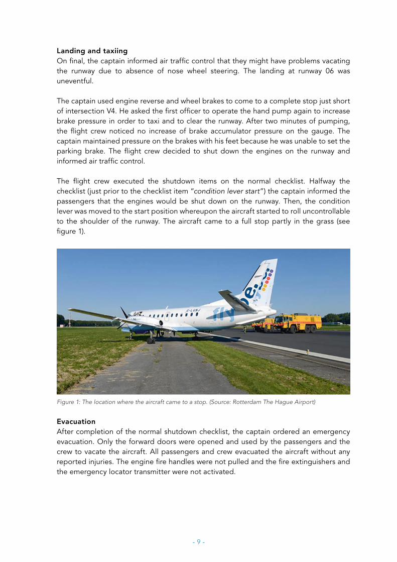
The flight crew executed the shutdown items on the normal checklist. Halfway the checklist (just prior to the checklist item “condition lever start”) the captain informed the passengers that the engines would be shut down on the runway. Then, the condition lever was moved to the start position whereupon the aircraft started to roll uncontrollable to the shoulder of the runway. The aircraft came to a full stop partly in the grass (see figure 1).
Figure 1: The location where the aircraft came to a stop. (Source: Rotterdam The Hague Airport)
EvacuationAfter completion of the normal shutdown checklist, the captain ordered an emergency evacuation. Only the forward doors were opened and used by the passengers and the crew to vacate the aircraft. All passengers and crew evacuated the aircraft without any reported injuries. The engine fire handles were not pulled and the fire extinguishers and the emergency locator transmitter were not activated.
- 10 -
The flight crew
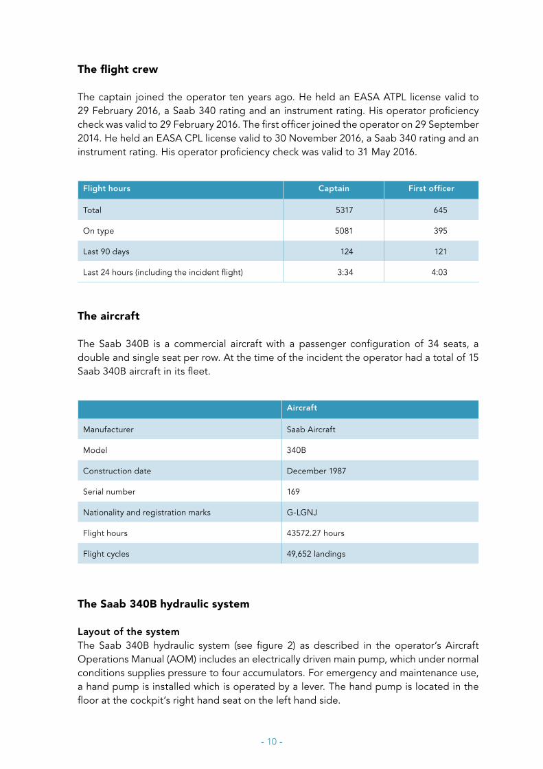
The captain joined the operator ten years ago. He held an EASA ATPL license valid to 29 February 2016, a Saab 340 rating and an instrument rating. His operator proficiency check was valid to 29 February 2016. The first officer joined the operator on 29 September 2014. He held an EASA CPL license valid to 30 November 2016, a Saab 340 rating and an instrument rating. His operator proficiency check was valid to 31 May 2016.
Flight hours Captain First officer
Total 5317 645
On type 5081 395
Last 90 days 124 121
Last 24 hours (including the incident flight) 3:34 4:03
The aircraft
The Saab 340B is a commercial aircraft with a passenger configuration of 34 seats, a double and single seat per row. At the time of the incident the operator had a total of 15 Saab 340B aircraft in its fleet.
Aircraft
Manufacturer Saab Aircraft
Model 340B
Construction date December 1987
Serial number 169
Nationality and registration marks G-LGNJ
Flight hours 43572.27 hours
Flight cycles 49,652 landings
The Saab 340B hydraulic system
Layout of the systemThe Saab 340B hydraulic system (see figure 2) as described in the operator’s Aircraft Operations Manual (AOM) includes an electrically driven main pump, which under normal conditions supplies pressure to four accumulators. For emergency and maintenance use, a hand pump is installed which is operated by a lever. The hand pump is located in the floor at the cockpit’s right hand seat on the left hand side.
- 11 -
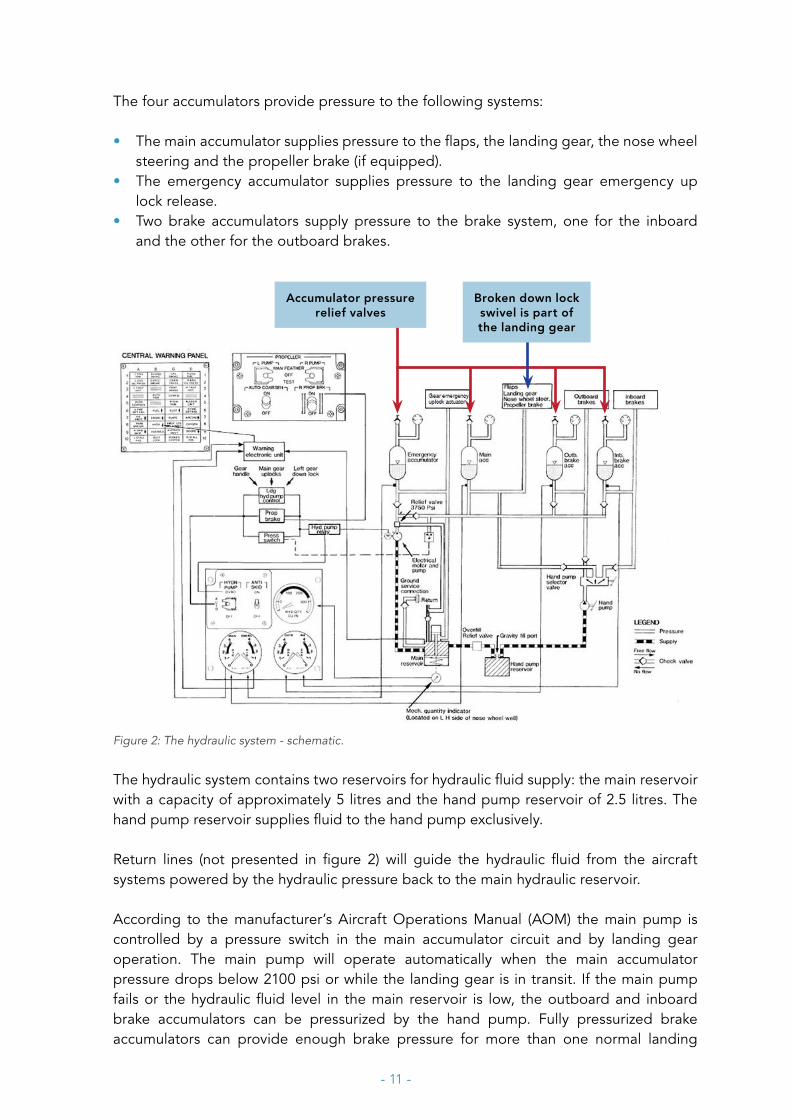
The four accumulators provide pressure to the following systems:
• The main accumulator supplies pressure to the flaps, the landing gear, the nose wheel steering and the propeller brake (if equipped).
• The emergency accumulator supplies pressure to the landing gear emergency up lock release.
• Two brake accumulators supply pressure to the brake system, one for the inboard and the other for the outboard brakes.
Accumulator pressure relief valves
Broken down lock swivel is part of the landing gear
Figure 2: The hydraulic system - schematic.
The hydraulic system contains two reservoirs for hydraulic fluid supply: the main reservoir with a capacity of approximately 5 litres and the hand pump reservoir of 2.5 litres. The hand pump reservoir supplies fluid to the hand pump exclusively.
Return lines (not presented in figure 2) will guide the hydraulic fluid from the aircraft systems powered by the hydraulic pressure back to the main hydraulic reservoir.
According to the manufacturer’s Aircraft Operations Manual (AOM) the main pump is controlled by a pressure switch in the main accumulator circuit and by landing gear operation. The main pump will operate automatically when the main accumulator pressure drops below 2100 psi or while the landing gear is in transit. If the main pump fails or the hydraulic fluid level in the main reservoir is low, the outboard and inboard brake accumulators can be pressurized by the hand pump. Fully pressurized brake accumulators can provide enough brake pressure for more than one normal landing

- 12 -
sequence. If the brake accumulator pressure drops below 1650 psi, which is the pre charged pressure of the brake accumulator, a sudden decrease of pressure towards zero may be experienced. A large number of hand pump strokes and continuous pumping is required to achieve and maintain enough brake pressure during landing and taxiing. The hand pump reservoir has a capacity of 150 cubic inches (2.5 litres). In theory with this capacity approximately 150 full hand pump lever strokes 1 are possible to pressurize the accumulators. The hand pump can only pressurize one accumulator at the time. The respective accumulator can be selected via the hand pump selector valve. According to the Saab 340B Aircraft Maintenance Manual; approximately 30-40 strokes are needed to increase the hydraulic pressure in one accumulator to operating pressure.
Pressure relief valves are present for all four accumulators. When the pressure increases to 3900 psi the pressure relief valves in that particular accumulator will open, decreasing the pressure in the accumulator by guiding the hydraulic fluid towards the return lines and into the main reservoir.
Hydraulic landing gear systemThe Saab 340B is equipped with a conventional retractable landing gear. All gears retract in a forward direction. Normal landing gear operation (gear up or gear down) is by hydraulic power provided by the main pump and the main accumulator, resulting in a constantly pressurized system during normal operations. A spring load will keep the gears down and locked. In an emergency situation the landing gear can be extended by free fall or by use of the hydraulic hand pump. In case of hydraulic failure, the gear may be extended by free fall. By pulling the landing gear emergency extension handle in the cockpit floor, the gear actuator hydraulic pressure lines will be connected to the return lines to prevent hydraulic lock.
1 Calculated value based on hand pump reservoir capacity divided with a theoretical volume per full stroke.

- 13 -
Figure 3: The landing gear system - schematic.
Emergency accumulator pressure will then release the uplocks and the gear will extend and lock by gravity and aerodynamic forces. When the hydraulic pressure in the main accumulator drops below 2100 psi due to hydraulic system usage or by a leak in the main hydraulic system, the hydraulic pressure switch will switch the main pump to on. In the event of a leak in the main system the main pump will continue to supply hydraulic pressure to the hydraulic system. To mitigate the risk of spilling excessive hydraulic fluid, the main pump must be switched off manually.
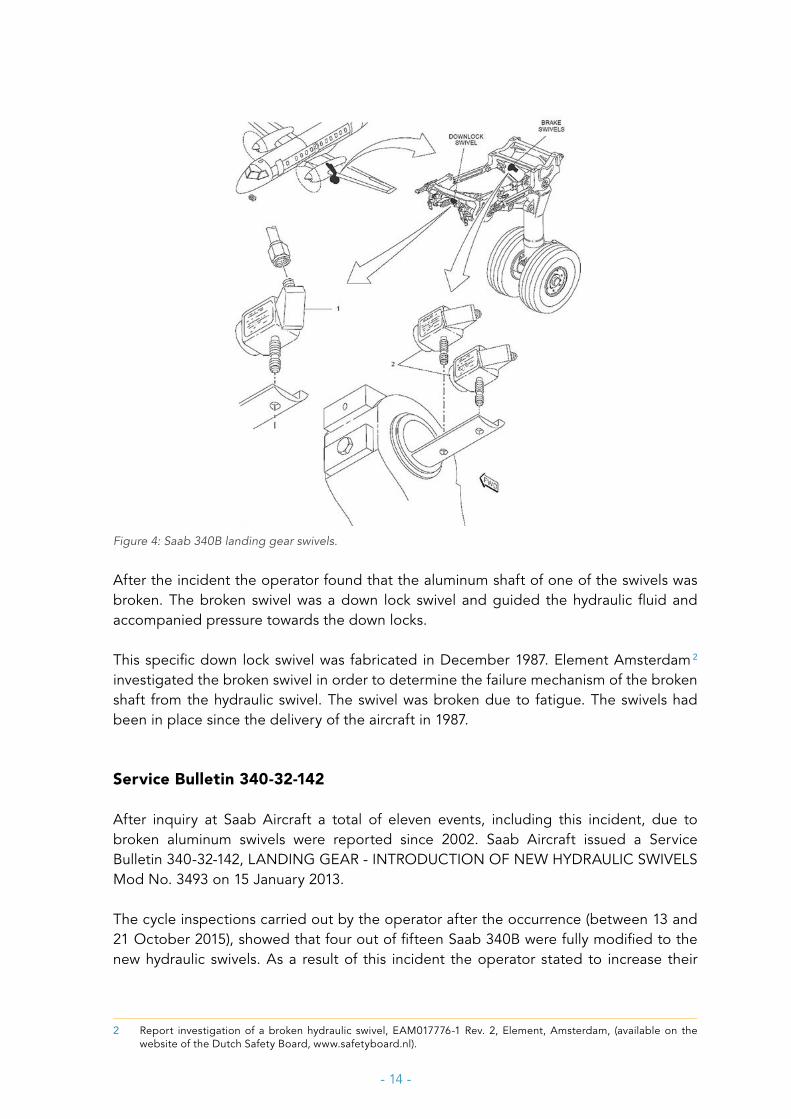
SwivelsThe Saab 340B hydraulic system contains six hydraulic swivels. A hydraulic swivel is a connection that allows the connected hydraulic lines to rotate. Hydraulic swivels are joints where the hydraulic fluid passes through. Three swivels are located on each main gear, one down lock swivel and two brake swivels. Each swivel consists of an aluminium block with aluminium hollow axes. Hydraulic fluid will flow through this aluminium block and hollow shaft.
- 14 -
Figure 4: Saab 340B landing gear swivels.
After the incident the operator found that the aluminum shaft of one of the swivels was broken. The broken swivel was a down lock swivel and guided the hydraulic fluid and accompanied pressure towards the down locks.
This specific down lock swivel was fabricated in December 1987. Element Amsterdam 2
investigated the broken swivel in order to determine the failure mechanism of the broken shaft from the hydraulic swivel. The swivel was broken due to fatigue. The swivels had been in place since the delivery of the aircraft in 1987.
Service Bulletin 340-32-142
After inquiry at Saab Aircraft a total of eleven events, including this incident, due to broken aluminum swivels were reported since 2002. Saab Aircraft issued a Service Bulletin 340-32-142, LANDING GEAR - INTRODUCTION OF NEW HYDRAULIC SWIVELS Mod No. 3493 on 15 January 2013.
The cycle inspections carried out by the operator after the occurrence (between 13 and 21 October 2015), showed that four out of fifteen Saab 340B were fully modified to the new hydraulic swivels. As a result of this incident the operator stated to increase their
2 Report investigation of a broken hydraulic swivel, EAM017776-1 Rev. 2, Element, Amsterdam, (available on the website of the Dutch Safety Board, www.safetyboard.nl).

- 15 -
effort to replace the remaining pre-modified aluminum swivels in their fleet and that the remaining pre-modified aluminum swivels will be replaced by modified swivels before the Final Report’s publication date.
Operational procedures
MalfunctionsAccording to the operator’s procedures (OM part B, page 3-1) the crew actions following any caution or warning are (explanatory text added in italic):
1. fly the aircraft;2. execute the memory items (memory items are coupled to specific malfunctions. These
items require immediate actions by memory if the situation arises. At first notice of any malfunction the crew will start the applicable memory items, only if and when the aircraft is in a controlled situation);
3. execute the emergency checklists (these are checklists that apply to specific malfunctions);
4. execute the normal checklist;5. execute the abnormal checklists (these are checklists that apply to specific malfunctions).
During take-off, it is necessary to suppress less important warnings in order not to distract the flight crew. Therefore, the take-off inhibit mode should be selected prior to take-off. The inhibit mode will deselect automatically after gear up selection or it can be deselected by manual cancelation of the inhibit mode. The indication of a hydraulic malfunction is one of the warnings that will be suppressed during take-off until the gear is selected up or the inhibit mode is cancelled manually.
Hydraulic malfunctionsA hydraulic malfunction will present itself to the flight crew as an HYDR caption light on the Central Warning Panel and is also visualised at the hydraulic pressure gauges and hydraulic fluid quantity gauges positioned at the pedestal. After analysing the malfunction the flight crew will start their failure management. In case of a hydraulic failure the crew actions are to execute:
1. fly the aircraft;2. the memory items that are needed:
– to shut off the electrical hydraulic pump; – if the hydraulic warning light is switched on to check the hydraulic pressure gauges
(page A32, see Appendix A);3. the emergency checklist:
– in case of a hydraulic failure no emergency checklists are available;4. the normal checklist;5. the abnormal checklist:
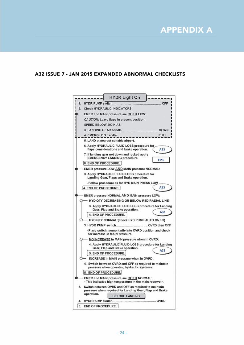
– the abnormal checklists following a hydraulic failure, HYDR Light On (page A32, see Appendix A) and HYDRAULIC FLUID LOSS (page A33, see Appendix B).
- 16 -
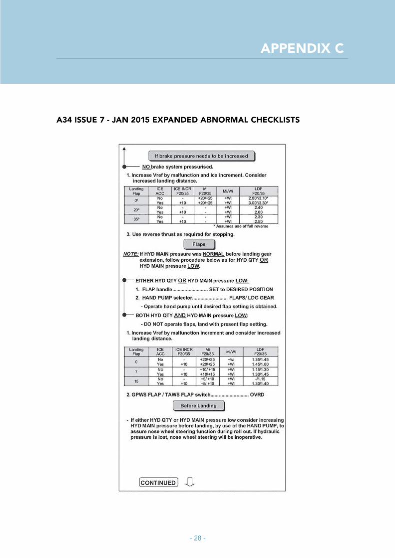
Deactivating the electrical hydraulic pump is necessary in order to reduce the pressure in the hydraulic lines and prevent excessive leaking of hydraulic fluid. In case of a low hydraulic main pressure associated with a hydraulic fluid quantity low indication the hand pump system is only available for pressurising the brake accumulators (Expanded Abnormal Checklist page A34, see Appendix C). The aircraft should be landed with the flaps setting present at the time of the malfunction.
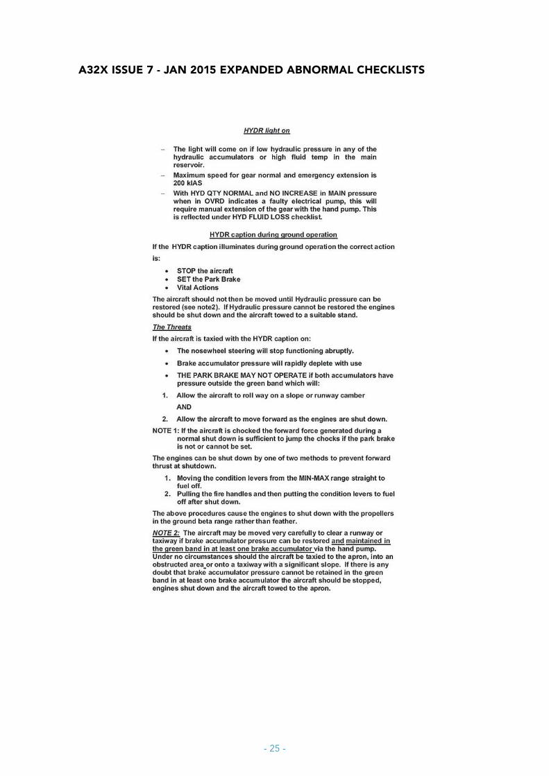
According to the operator’s OM following a hydraulic malfunction special attention should be noted to ground operations. When hydraulic pressure cannot be restored the aircraft should not be moved, the engines should be shut down and the aircraft towed to a suitable stand, since the brake accumulator pressure will rapidly deplete with use. If brake pressure can be maintained in the normal operating range in at least one brake accumulator via the hand pump, then the aircraft can be moved very carefully to clear the runway (Expanded Abnormal Checklist page A32x, Appendix A).
Effect of hydraulic failure on the engine shut-down procedureThe notes in the Expanded Abnormal Checklist (page A32x, Appendix A) provided by the operator instruct the crew to follow a different engine shutdown procedure when a hydraulic failure exists resulting in a loss of brake pressure. The alternate shutdown procedure is to prevent an unwanted forward thrust while the propellers move to feather with the possibility of an uncontrollable forward movement of the aircraft. The crew should use one of two methods to shut down the engines (Expanded Abnormal Checklist page A32x, see Appendix A):
1. Moving the condition levers from the Min-Max range straight to fuel off.2. Pulling the engine fire handles and then putting the condition levers to fuel off after
shut down.
The above procedures cause the engines to shut down with the propellers in the ground beta range, avoiding any increase in thrust at the moment the propellers move to feather.
Ground evacuationThe operator issued a decision tree in OM part B, page 11-14, to aid the captain of an aircraft in the decision to order an emergency evacuation or precautionary evacuation for the occupants (see figure 5). The assessment leads to three possibilities: evacuation, deplane, or normal disembarkation.

- 17 -
Figure 5: Operator’s decision tree for emergency/abnormal evacuation assessment.
The operations manual lists a number of examples when to evacuate the aircraft including the situation when the aircraft has left the paved surface and the integrity of the aircraft is uncertain.
An emergency evacuation should be ordered by the captain if there is an imminent danger for the occupants on board of the aircraft. According the operator’s OM an emergency evacuation is very likely to result in a considerable number of injuries to the passengers due to the height of the forward exits above the ground. The passengers vacate the aircraft as soon as possible at any available exit while leaving all their hand baggage behind. There are two forward exits and two over wing exits. Additional actions for the crew are to pull the engine fire handles and the fire extinguishers, and to activate the Emergency Locator Transmitter.
The aircraft should be deplaned when there is no immediate threat or injury to the passengers or crew, but there is a considerable risk to the occupants if the situation deteriorates, or if the situation is uncertain. While deplaning the passengers vacate the aircraft as soon as practicable at the forward passenger exit. In these circumstance passengers are allowed to take their hand baggage with them. The operator’s OM addresses no example for deplaning in the situation of an aircraft departed the paved surface.
The passengers may disembark the aircraft the normal way when there is no imminent danger, immediate threat or risk to the occupants on board of the aircraft and the situation is stable.
- 18 -
ANALYSIS
The actual aircraft component failure during the flight with the Saab 340B on 30 September 2015, leading to the main hydraulic system failure, was a broken down lock swivel in the right main landing gear. In January 2013 Saab Aircraft issued a Service Bulletin to replace the aluminum hydraulic swivels with modified swivels. The broken swivel was of the pre-modification, aluminum type.
Saab 340B hydraulic system
Redundancy of the systemThe Saab 340B came to a stop in the shoulder near the runway at Rotterdam airport as a result of a hydraulic system malfunction. The sequence of events raised the question whether the failure of the main hydraulic system precluded to continue a safe flight with the aircraft’s redundant systems.
In the event flight, the low hydraulic main pressure and low hydraulic fluid quantity, caused by the leaking down lock swivel, reduced the hydraulic system to the emergency hydraulic system. The emergency hydraulic system will operate the gear up lock activator by a separate accumulator and the hand pump system to provide hydraulic pressure to the left and right hand brake accumulator or flaps depending of the selection of the manual selector valve. Since the leaking down lock swivel was part of the main hydraulic system, to increase the hydraulic pressure was restricted to the left and right brake accumulators by hand pump. A safe landing configuration would be considered a configuration with the landing gear down and usable wheel brakes throughout the landing phase. The landing gear was available by the emergency landing gear extension procedure. The hand pump could provide hydraulic pressure to the left and right brake accumulator as long as the hydraulic fluid was available in the hand pump reservoir. According the operator’s OM the available hydraulic fluid in the hand pump reservoir would be sufficient for at least one landing. The aircraft hydraulic system provided redundancy in this particular situation.
Risk of spilling hydraulic fluid by using the hand pump systemApproximately 150 full strokes by hand pump are available before emptying the 2.5 litres hydraulic fluid in the hand pump reservoir. The pressure in both brake accumulators was in the normal operating range when flying in the Rotterdam holding. The flight crew decided to use the hand pump to increase the pressure in both brake accumulators further for a period of approximately six minutes in order to have as much braking power as possible. The number of hand pump strokes applied by the first officer in that period could not be determined. The notes in the expanded checklists HYDRAULIC FLUID LOSS could give the flight crew the impression that hydraulic fluid in the hand pump system is unlimited. The notes explain that a large number of hand pump strokes and continuous pumping is required to achieve and maintain enough brake pressure. The possibility
- 19 -
exists that continuous pumping could create an overpressure of approximately 3900 psi which will open the relief valves in the hand pump hydraulic system. This would spill hydraulic fluid into the main hydraulic system and with a main hydraulic system leak also loose hydraulic fluid from the hand pump system.
Saab Aircraft Service Bulletin 340-32-142
Saab Aircraft issued a Service Bulletin to replace the current swivel with a modified swivel L38710-SS on 15 January 2013. Although the leakage in the hydraulic system of the Saab 340B was the result of a broken down lock swivel L38710-SA, the aircraft hydraulic system provides enough redundancy (see paragraph Redundancy of the system) to validate the issuing of a (non-compulsory) Service Bulletin instead of a (restrictive) Airworthiness Directive.
Crew
According to the information received from the flight crew and the operator, the crew was qualified to fly the aircraft, the captain was experienced on the type and the flight crew followed the training in accordance with the operator’s OM.
Operational procedures
Procedures regarding hydraulic abnormalitiesA HYDR caption light on the Central Warning Panel and an aural warning were activated during the initial climb. According to the procedures (memory items), in case of a hydraulic failure, the electrical hydraulic pump shall be switched off. The flight crew delayed switching off the electrical hydraulic pump until they started reading the expanded abnormal checklist. Therefore, a prolonged loss of hydraulic fluid occurred. However, the prolonged loss of hydraulic fluid did not hinder the outcome of events. No clear reason was found to explain the delayed switching off of the hydraulic pump.
The hydraulic abnormal checklists in the operator’s OM are extensive checklists, including many conditional statements leading the flight crew to the other checklists if the situation dictates. The flight crew started with the HYDR Light On checklist page A32 (Appendix A). This checklist includes important notes at page A32x (Appendix A) covering ground operations with hydraulic malfunctions. These notes concern alternate engine shutdown procedures when a hydraulic failure exists and threats when the aircraft is taxied with the HYDR caption on and loosing brake accumulator pressure. These notes can easily been overseen, because it is not included in the checklist actions on page A32. Particularly when the conditional statement main hydraulic pressure low and hydraulic quantity low is true, then the flight crew is directed towards the checklist covering HYDRAULIC FLUID LOSS on page A33x (Appendix B). When they proceed on that page, they do not read about the threats applicable to HYDR caption light on during the ground operations anymore. Following the checklist, page A34 ends with a consideration to increase the
- 20 -
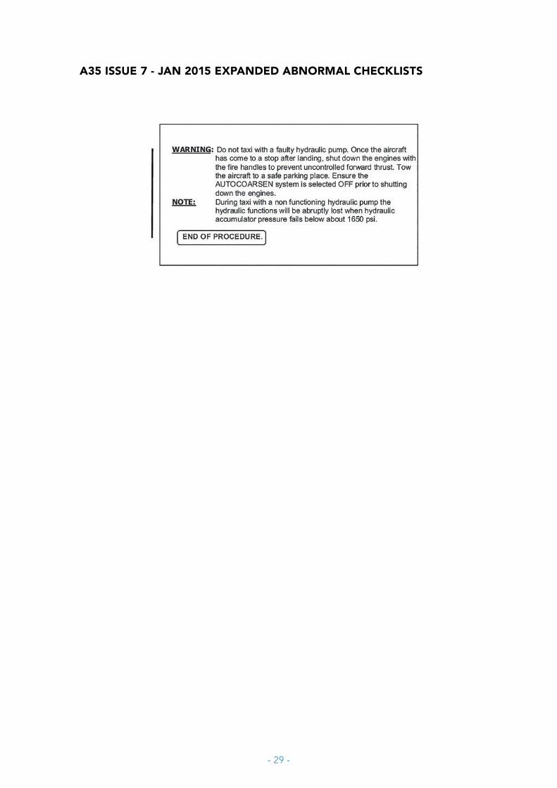
hydraulic main pressure before landing. Page A35 contains the warning and a note regarding the after landing procedures (Appendix C).
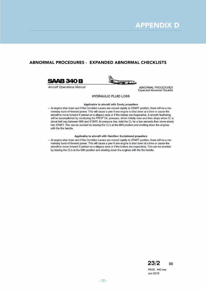
In the Saab Aircraft AOM a note is included concerning the abnormal engine shutdown procedure in concert with loss of hydraulic brake pressure in the manufactures HYDRAULIC FLUID LOSS checklist page A42 exp (Appendix D). Providing the abnormal engine shutdown procedures in the after landing section, will increase the crew awareness of the applicable abnormal engine shutdown procedures.
The manufacturer and the operator informed that they are in the process of amending the HYDRAULIC FLUID LOSS and HYD Light On checklists in order to address ground operation with hydraulic malfunctions in a clear and more directive manner. This will eliminate the possibility that flight crews miss these notes and subsequently do not follow the alternate shutdown procedure resulting in uncontrolled forward movement of the aircraft due to increased engine thrust while the propellers feather. Furthermore, the updated checklist contains an instruction not to taxi with a HYDR caption light on.
The HYDRAULIC FLUID LOSS notes on page A33x repeatedly warned that continuous pumping of the brakes is required to achieve and maintain enough brake pressure. No particular attention is given to the limited amount of hydraulic fluid in the hand pump reservoir and the associated limited number of (150) lever strokes, while the note in the expanded checklist gives the impression that this capacity is unlimited.
Evacuation procedureAccording to the operator’s OM the emergency evacuation procedure can easily lead to multiple injuries of passengers exiting the aircraft. Therefore, the flight crew should make the best possible decision for the situation. In this situation the captain solely based his decision to emergency evacuate the aircraft on the fact that the aircraft had left the paved surface. The captain did not follow the company’s procedures as depicted in the decision tree (See figure 5). According to this procedure, the best possible way to disembark the passengers in the current situation was a normal disembarkation.
- 21 -
CONCLUSIONS, MEASURES AND ACTIONS
Conclusions
Conclusion 1The serious incident on 30 September 2015 with the Saab 340B at Rotterdam The Hague Airport was initiated by a broken aluminum down lock swivel of the right hand main landing gear due to fatigue. This problem was recognized by Saab Aircraft and they issued a non-compulsory Service Bulletin 340-32-142 to replace the aluminum swivels.
The Saab 340B hydraulic system provides sufficient redundancy to continue safe operation when an aluminum swivel fails. The non-compulsory Service Bulletin 340-32-142 issued by Saab Aircraft to replace the aluminum swivels instead of an Airworthiness Directive is therefore acceptable.
Conclusion 2The flight crew delayed the appropriate memory item, hydraulic pump switch off, during the hydraulic failure. No particular reason was found.
Conclusion 3The layout of the hydraulic malfunction checklists, and the missing engine shutdown procedure made the flight crew to shut down the engine by the normal procedure. This resulted in an uncontrolled forward motion of the aircraft which ended in the grass next to the runway, with neither braking nor nose wheel steering capabilities.
Conclusion 4When the central hydraulic system fails, one has to rely on the hydraulic backup systems. The HYDRAULIC FLUID LOSS Expanded Abnormal Checklist gives the impression that operation of the hand pump lever hydraulic system is unlimited, while in practice this is limited to approximately 150 lever strokes.
The outcome of this incident however was influenced by the decision of the flight crew to increase the pressure of the brake accumulators by using the hand pump, although the brake accumulators were already on working pressure capable of at least one full landing. The activation of the hand pump, with the brake accumulators on normal hydraulic pressure, may create an overpressure resulting in the activation of the relief valve spilling the limited available hydraulic fluid overboard.
The loss of brake pressure on the runway may have been avoided if the flight crew was more aware of the limitations of the hand pump hydraulic system.

- 22 -
Conclusion 5After the aircraft stopped in the grass next to the runway, there were no imminent threats for aircraft occupants and the aircraft integrity was evident. Therefore a normal disembarkation was possible.
Measures and actions
After this incident the operator replaced all pre-modified aluminum swivels in her Saab 340B fleet.
Due to previous Saab 340B hydraulic malfunctions the manufacturer and the operator are in the process of amending the HYDRAULIC FLUID LOSS and HYD Light On checklists. The amended checklists will address ground operation with hydraulic malfunctions in a clear and more directive manner.
The occurrence was not serious enough for an interim recommendation because no reports are known of similar incidents. In response to conclusion 4 the Dutch Safety Board issued two recommendations to the manufacturer and in response to conclusions 2 and 5 the Dutch Safety Board issued a recommendation to the operator.

- 23 -
RECOMMENDATIONS
Based on the conclusions and actions taken the Dutch Safety Board made the following recommendations.
1. Saab Aircraft is recommended to amend the HYDRAULIC FLUID LOSS Expanded Abnormal checklist to include information about the limited operational capability of the hand pump system, because when the central hydraulic system fails one has to rely on the hydraulic backup systems.3
2. Saab Aircraft is recommended to address Saab 340 operators that pilot’s basic and recurrent technical training include more awareness about the hand pump system limitations and the possibility of overpressure and the consequences during a hydraulic fluid loss event.4
3. The operator is recommended to increase awareness of pilots during recurrent training of:a. timely initiation of the memory items, direct relevant to flight safety;b. the considerations given by the operator about an evacuation in relation to the
risk of injuries of the passengers.5
3 The safety recommendation reference number in the European Safety Recommendation Information System (SRIS) is NL.SIA-2016-0002.
4 The safety recommendation reference number in the European Safety Recommendation Information System (SRIS) is NL.SIA-2016-0003.
5 The safety recommendation reference number in the European Safety Recommendation Information System (SRIS) is NL.SIA-2016-0004.
- 24 -
AppENDIx A
A32 ISSUE 7 - JAN 2015 ExpANDED ABNORMAL CHECKLISTS
- 25 -
A32x ISSUE 7 - JAN 2015 ExpANDED ABNORMAL CHECKLISTS

- 26 -
AppENDIx B
A33 ISSUE 7 - JAN 2015 ExpANDED ABNORMAL CHECKLISTS

- 27 -
A33x ISSUE 7 - JAN 2015 ExpANDED ABNORMAL CHECKLISTS
- 28 -
AppENDIx C
A34 ISSUE 7 - JAN 2015 ExpANDED ABNORMAL CHECKLISTS
- 29 -
A35 ISSUE 7 - JAN 2015 ExpANDED ABNORMAL CHECKLISTS
- 30 -
AppENDIx D
ABNORMAL pROCEDURES - ExpANDED ABNORMAL CHECKLISTS

- 31 -

DUTCHSAFETY BOARD
Visiting Address Anna van Saksenlaan 50 2593 HT The HagueT +31(0)70 333 70 00 F +31(0)70 333 70 77
Postal Address PO Box 95404 2509 CK The Hague
www.safetyboard.nl