RTR 213-01 I · VOLUME III: ASRB PLUME ... ED33, COTR. This report is presented in three volumes:...
30
I I I I I I I I I I I I I I I I I I I SRB ENVIRONMENT EVALUATION AND ANALYSIS FINAL REPORT VOLUME III: ASRB PLUME INDUCED ENVIRONMENTS September 1991 Prepared by: R. L Bender J. R. Brown J. E. Reardon J. Everson L W. Coons C. I. Stuckey M. S. Fulton Contract: NAS8-37891 For: Induced Environments Branch (E033) National Aeronautics and Space Administration George C. Marshall Space Flight Center Marshall Space Flight Center, AL 35812 RTR 213-01 https://ntrs.nasa.gov/search.jsp?R=19930016865 2018-06-11T00:11:06+00:00Z
-
Upload
dinhkhuong -
Category
Documents
-
view
215 -
download
1
Transcript of RTR 213-01 I · VOLUME III: ASRB PLUME ... ED33, COTR. This report is presented in three volumes:...
I I I I I I I I I I I I I I I I I I I
SRB ENVIRONMENT EVALUATION AND ANALYSIS
FINAL REPORT
VOLUME III: ASRB PLUME INDUCED ENVIRONMENTS
September 1991
Prepared by:
R. L Bender J. R. Brown
J. E. Reardon J. Everson
L W. Coons C. I. Stuckey M. S. Fulton
Contract:
NAS8-37891
For:
Induced Environments Branch (E033) National Aeronautics and Space Administration
George C. Marshall Space Flight Center Marshall Space Flight Center, AL 35812
RTR 213-01
https://ntrs.nasa.gov/search.jsp?R=19930016865 2018-06-11T00:11:06+00:00Z
I_ EEM T IE C I'1 RTR 213-01
FOREWORD
This Technical Report documents the results of the analyses done on the redesignedSolid Rocket Booster (SRB) performed by REMTECH inc., under NASA/MSFC ContractNAS8-37891, Mr. L. D. Foster, ED33, COTR. This report is presented in three volumes:
Volume I:
Volume I1:
Volume II1:
Redesigned SRB Flight Heating Evaluation
RSRB Joint Filling Test/Analysis Improvements
ASRB Plume Induced Environments
Volume III documents analyses and technical support related to model and full-scale radiation measurement tests, design cycle environment generation, development
flight instrumentation, and ASRB Thermal Panel participation over the time period fromDecember 1989 through September 1991.
RTR 21~1
FOREWORD This Technical Report documents the results of the analyses done on the redesigned
Solid Rocket Booster (SRB) performed by REMTECH inc., under NASAlMSFC Contract NAS8-37891, Mr. L. D. Foster, ED33, COTR. This report is presented in three volumes:
Volume I: Volume II: Volume III:
Redesigned SRB Flight Heating Evaluation RSRB Joint Filling Test/Analysis Improvements ASRB Plume Induced Environments
Volume III documents analyses and technical support related to model and fullscale radiation measurement tests, design cycle environment generation, development flight instrumentation, and ASRB Thermal Panel participation over the time period from December 1989 through September 1991.
!=_ EEMTE C I---! RTR 213-01
ABSTRACT
Contract NAS8-37891 was expanded in late 1989 to initiate analysis of Shuttle
plume induced environments as a result of the substitution of the Advanced SolidRocket Booster (ASRB) for the Redesigned Solid Rocket Booster (RSRB). To supportthis analysis, REMTECH became involved in subscale and full-scale solid rocket motortest programs which further expanded the scope of work. Later contract modificationsincluded additional tasks to produce initial design cycle environments and to specify
development flight instrumentation. Volume III of the final report describes these analysesand contains a summary of reports resulting from various studies. This work was
performed under the direction of Mr. Peter Sulyma of MSFC's Induced EnvironmentBranch, ED33.
RTR 213-01
ABSTRACT Contract NAS8-37891 was expanded in late 1989 to initiate analysis of Shuttle
plume induced environments as a result of the substitution of the Advanced Solid Rocket Booster (ASRB) for the Redesigned Solid Rocket Booster (RSRB). To support this analysis, REMTECH became involved in subscale and full-scale solid rocket motor test programs which further expanded the scope of work. Later contract modifications included additional tasks to produce initial design cycle environments and to specify development flight instrumentation. Volume III of the final report describes these analyses and contains a summary of reports resulting from various studies. This work was performed under the direction of Mr. Peter Sulyma of MSFC's Induced Environment Branch, ED33.
ii
I=:_I_: rvl-r- _" C_ I---.I RTR 213-01
Contents
FOREWORD ............................................. i
ABSTRACT ............................................. ii
List of Figures ........................................... ivList of Tables ............................................. v
1 SUMMARY ............................................ 1
1.1 Contract Modification Chronology ............................ 1
1.2 Objectives .......................................... 12 ACCOMPLISHMENTS ..................................... 3
2.1 Radiation Measurement Test Support ......................... 32.1.1 Radiometers ...................................... 3
2.1.2 MNASA Motor Tests ................................. 6
2.1.3 Full-Scale SRM Tests ................................. 7
2.1.4 ASRM Tests ...................................... 7
2.2 ASRB Design Cycle Plume Induced Environments ................. 8
2.3 ASRB DFI Planning and Coordination ........................ 15
2.4 ASRB Thermal Panel Support ........ ..................... 163 REFERENCES ......................................... 23
iii
RTR 213-01
Contents
FOREWORD .................................... " ....... i ABSTRACT ............................................. ii List of Figures. . . . . . . . . . . . . . . . . . . . . . . . . . . . . . . . . . . . . . . . . .. iv List of Tables. . . . . . . . . . . . . . . . . . . . . . . . . . . . . . . . . . . . . . . . . . . . . v 1 SUMMARY ............................................ 1
1.1 Contract Modification Chronology. . . . . . . . . . . . . . .............. 1 1.2 Objectives ..... . . . . . . . . . . . . . . . . . . . . . . . . . . . . . . . . . . . . . 1
2 ACCOMPLISHMENTS ..................................... 3 2.1 Radiation Measurement Test Support . . . . . . . . . . . . . . . . . . . . ..... 3
2.1.1 Radiometers . . . . . . . . . . . . . . . . . . . . . . . . . . . . . . . ....... 3 2.1.2 MNASA Motor Tests ............... .................. 6 2.1.3 Full-Scale SRM Tests. . . . . . . . . . . . . . . .................. 7 2.1.4 ASRM Tests ...................................... 7
2.2 ASRB Design Cycle Plume Induced Environments . . . . . ............ 8 2.3 ASRB DFI Planning and Coordination ........................ 15 2.4 ASRB Thermal Panel Support ......... ' . . . . . . . . . . . . . . . . . . . . 16
3 REFERENCES . . . . . . . . . . . . . . . . . . . . . . . . . . . . . . . . . . . . . . . . . 23
iii
I:_ E I',,A T E C I-"1 RTR 213-01
List of Figures
1 Chamber Pressure Histories Used in 5/91 Plume Induced Heating Trajectory
Sensitivity Study ......................................... 112 Sensitivity of 5/91 ASRB Convective Base Heating Environments to Trajectory
Propulsion and Operational Parameters .......................... 123 8/91 Trajectory Comparisons Used in Convective Heating Sensitivity Study .... 134 Summary of Convective Results for 8/20/91 Trajectory Sensitivity Study ...... 145 Cover Sheet to April 1991 DFI Presentation ........................ 186 Shuttle with ASRB Induced Thermal Environments and DFI Requirements
Status ............................................... 197 DFI m Shuttle with ASRB m Justification ......................... 208 Necessity of DFI for Initial Flights m Shuttle with ASRB _ Conclusions ...... 219 Induced Thermal Environments _ Shuttle with ASRM m Summary ........ 22
iv
RTR 213-<l1
List of Figures 1 Chamber Pressure Histories Used in 5/91 Plume Induced Heating Trajectory
Sensitivity Study . . . . . . . . . . . . . . . . . . . . . . . . . . . . . . . . . . . . . . . . . 11 2 Sensitivity of 5/91 ASRB Convective Base Heating Environments to Trajectory
Propulsion and Operational Parameters . . . . . . . . . . . . . . . . . . . . . . . . . . 12 3 8/91 Trajectory Comparisons Used in Convective Heating Sensitivity Study. . . . 13 4 Summary of Convective Results for 8/20/91 Trajectory Sensitivity Study . . . . . . 14 5 Cover Sheet to April 1991 OFI Presentation ........................ 18 6 Shuttle with ASRB Induced Thermal Environments and OFI Requirements -
Status ............................................... 19 7 OFI - Shuttle with ASRB - Justification . . . . . . . . . . . . . . . . . . . . . . . . . 20 8 Necessity of OFI for Initial Flights - Shuttle with ASRB - Conclusions . . . . . . 21 9 Induced Thermal Environments - Shuttle with ASRM - Summary ........ 22
iv
I:_ EE I_d -1- EE C I'-'1 RTR 213-01
List of Tables
1 Radiometers Purchased on the Contract ........................... 4
2 Report Summary: Radiation Measurement Test Support ................. 8
3 Report Summary: ASRB Design Cycle Plume Induced Environments ....... 104 Report Summary: ASRB DFI Planning and Coordination ............... 16
V
RTR 213-01
List of Tables 1 Radiometers Purchased on the Contract. . . . . . . . . . . . . . . . . . . . . . . . ... 4 2 Report Summary: Radiation Measurement Test Support . . . . . . . . . . . . . . . .. 8 3 Report Summary: ASRB Design Cycle Plume Induced Environments ....... 10 4 Report Summary: ASRB DFI Planning and Coordination ............... 16
v
I_ I_" M T _" C I,--! RTR 213-01
Section 1SUMMARY
The scope of work for contract NAS8-37891 was expanded in late 1989 to initi-ate analysis of Shuttle plume induced environments as a result of the substitution ofthe Advanced Solid Rocket Booster (ASRB) for the Redesigned Solid Rocket Booster(RSRB). To support this analysis, REMTECH became involved in subscale and full-scale solid rocket motor test programs which further expanded the scope of work. Latercontract modifications included additional tasks to produce initial design cycle environ-ments and to specify development flight instrumentation. An overview of these analysesand a summary of reports resulting from these studies is presented in Section 2. Thefollowing discussion highlights the various contract modifications, their objectives, andREMTECH's accomplishments.
1.1 Contract Modification Chronology
The efforts reported in Volume III of the final report began with Modification 5 to thecontract which was initiated December 14, 1989. The next three modifications (6, 7,and 8) followed closely after Modification 5 to involve REMTECH in the purchase andimplementation of radiometers to support the various test programs. Modifications 6, 7,and 8 were activated in December 1989 and March 1990, respectively. Modification 9 inAugust 1990 began the work directed toward producing the ASRB Cycle 1 design baseheating environments which were published in February 1991. Modification 10 was aninterim cost adjustment initiated in October 1990.
Following completion of the Cycle 1 environments in February 1991, work to updatethe methodology and initiate the Cycle 1.5 environment determination was began underModification 11 in April 1991. This effort was continued through September 1991 underModification 12. The total period of performance spanned approximately 22 months andinvolved, in total, 8 separate contract modifications.
1.2 Objectives
The primary objective of these contract extensions was to involve REMTECH andits subcontractor, SECA, Inc. in the early phases of the assessment of changes in theNational Space Transportation System (Space Shuttle) ascent aerothermal environmentsresulting from the substitution of the ASRB for the RSRB. The focus was on identifyingand specifying the plume induced environments by defining the ASRB plumes andresulting impact of the different (from RSRB) plumes on Shuttle element base heating.To accomplish this objective, a vadety of tasks and individual analyses were performed.These various tasks fell into three general categories.
1. Empirical Data Base Support2. Base Heating Methodology Development
Re::..........,..,-e::C H
Section 1 SUMMARY
RTR 213-01
The scope of work for contract NAS8-37891 was expanded in late 1989 to initiate analysis of Shuttle plume induced environments as a result of the substitution of the Advanced Solid Rocket Booster (ASRB) for the Redesigned Solid Rocket Booster (RSRB). To support this analysis, REMTECH became involved in subscaJe and fullscale solid rocket motor test programs which further expanded the scope of work. Later contract modifications included additional tasks to produce initial design cycle environments and to specify development flight instrumentation. An overview of these analyses and a summary of reports resulting from these studies is presented in Section 2. The following discussion highlights the various contract modifications, their objectives, and REMTECH's accomplishments.
1.1 Contract Modification Chronology
The efforts reported in Volume III of the final report began with Modification 5 to the contract which was initiated December 14, 1989. The next three modifications (6, 7, and 8) followed closely after Modification 5 to involve REMTECH in the purchase and implementation of radiometers to support the various test programs. Modifications 6, 7, and 8 were activated in December 1989 and March 1990, respectively. Modification 9 in August 1990 began the work directed toward producing the ASRB Cycle 1 design base heating environments which were published in February 1991. Modification 10 was an interim cost adjustment initiated in October 1990.
Following completion of the Cycle 1 environments in February 1991, work to update the methodology and initiate the Cycle 1.5 environment determination was began under Modification 11 in April 1991. This effort was continued through September 1991 under Modification 12. The total period of performance spanned approximately 22 months and involved, in total, 8 separate contract modifications.
1.2 Objectives The primary objective of these contract extensions was to involve REMTECH and
its subcontractor, SECA, Inc. in the early phases of the assessment of changes in the National Space Transportation System (Space Shuttle) ascent aerothermal environments resulting from the substitution of the ASRB for the RSRB. The focus was on identifying and specifying the plume induced environments by defining the ASRB plumes and resulting impact of the different (from RSRB) plumes on Shuttle element base heating. To accomplish this objective, a variety of tasks and individual analyses were performed. These various tasks fell into three general categories.
1. Empirical Data Base Support 2. Base Heating Methodology Development
1

I_ EE M "!- _:: C I---I RTR 213-01
3. Design Cycle Environment Specification.
These individual efforts were pursued simultaneously, in most cases, and generally
complemented each other.
2
RTR 213-01
3. Design Cycle Environment Specification.
These individual efforts were pursued simultaneously, in most cases, and generally complemented each other.
2
I:_ E r%/IT E C I---I RTR 213-01
Section 2ACCOMPLISHMENTS
REMTECH and SECA's efforts through the 22 months of performance on this phaseof the contract produced a variety of reports, schematics and test support information, in-strumentation lists, environment packages, and handout materials which were distributedto the ASRB Thermal Panel. Much of this information was not formally documented byREMTECH or SECA, but was introduced into the ASRB program generically as MSFC
ED33 input. Therefore, to address our accomplishments on the contract requires dis-cussion of our individual efforts from inception to completion with specific output and
deliveries noted as they occurred.
This work has been separated into four major categories with discussion plus a listingof reports provided for each category. Originally, our support to the development flightinstrumentation specification and ASRB Thermal Panel was expected to be minimal.However, these studies ultimately consumed a substantial part of our total effort andwere, therefore, selected as separate categories.
2.1 Radiation Measurement Test Support
Experimental radiation work included three motor test programs: the 48-inch (casediameter) MNASA motor tests at MSFC, full-scale RSRM motor firings at the Thiokolfacility in Utah, and the full-scale ASRM tests at Stennis Space Center. The tasks in thiswork included: selection and purchasing of instrumentation, instrument custodial services
(shipping to tests, procurement of calibrations and record keeping), preparation of testrequirements indicating instrument type and locations, coordination of measurementsby others, and evaluation of the test results. The instrumentation responsibilities andaccomplishments on the test programs will be described below. A summary of all contractreports pertinent to radiation measurement test support is provided in Table 2 at the endof this subsection.
2.1.1 Radiometers
Initially, a range of radiometer designs were selected to provide a set capable ofperforming a range of measurement functions, but as the test requirements becamemore precisely defined, the type of radiometers procured became more specific. Mostof the radiometers procured near the end of the work were narrow-view units with a 4-degree (included angle) field of view designed to view a source with an emission rangeof up to 100 BTU/ft2-sec. The radiometers procured are listed in Table 1 with notes toindicate the number of tests each was used on and its current condition.
As each instrument is procured, it is entered into a data base which is used to trackthe instrument location, to record tests it has been used on, and to provide a history ofthe calibration results. After each use, the instrument is sent to the manufacturer for
3
Section 2 ACCOMPLISHMENTS
RTR 213-01
REMTECH and SECA's efforts through the 22 months of performance on this phase of the contract produced a variety of reports, schematics and test support information, instrumentation lists, environment packages, and handout materials which were distributed to the ASRB Thermal Panel. Much of this information was not formally documented by REMTECH or SECA, but was introduced into the ASRB program generically as MSFC ED33 input. Therefore, to address our accomplishments on the contract requires discussion of our individual efforts from inception to completion with specific output and deliveries noted as they occurred.
This work has been separated into four major categories with discussion plus a listing of reports provided for each category. Originally, our support to the development flight instrumentation specification and ASRB Thermal Panel was expected to be minimal. However, these studies ultimately consumed a substantial part of our total effort and were, therefore, selected as separate categories.
2.1 Radiation Measurement Test Support Experimental radiation work included three motor test programs: the 48-inch (case
diameter) MNASA motor tests at MSFC, full-scale RSRM motor firings at the Thiokol facility in Utah, and the full-scale ASRM tests at Stennis Space Center. The tasks in this work included: selection and purchasing of instrumentation, instrument custodial services (shipping to tests, procurement of calibrations and record keeping), preparation of test requirements indicating instrument type and locations, coordination of measurements by others, and evaluation of the test results. The instrumentation responsibilities and accomplishments on the test programs will be described below. A summary of all contract reports pertinent to radiation measurement test support is provided in Table 2 at the end of this subsection.
2.1.1 Radiometers Initially, a range of radiometer designs were selected to provide a set capable of
performing a range of measurement functions, but as the test requirements became more precisely defined, the type of radiometers procured became more specific. Most of the radiometers procured near the end of the work were narrow-view units with a 4-degree (included angle) field of view designed to view a source with an emission range of up to 100 BTU/ft2-sec. The radiometers procured are listed in Table 1 with notes to indicate the number of tests each was used on and its current condition.
As each instrument is procured, it is entered into a data base which is used to track the instrument location, to record tests it has been used on, and to provide a history of the calibration results. After each use, the instrument is sent to the manufacturer for
3
F_
I_M
'T"
E_
_i-'--I
RT
R213-01
#.oo.
00
00
00
0,00
0O
0
=1_==
=,=
=_,=
1_N
e,ee
ee,e,e
NN
='
8
0000000001000
_S3
r._
.=c_,C
;a.a.c_;a'",""""lU-I
''w
ww
'oo°°°
4
.J:io.
Table 1: Radiometers Purchased on the Contract
MEDTHERM Field of Sapphire Model Number View Window
(Degree) NVRW-100-4-20246 4 Yes * NVRW-100-4-20246 4 Yes • NVRW-100-4-20246 4 Yes • NVRW-100-4-20246 4 Yes • NVRW-100-4-20246 4 Yes • NVRW-100-4-20246 4 Yes • NVRW-100-4-20246 4 Yes • NVRW-100-4-20246 4 Yes • NVRW-056-4-20430 4 Yes • NVRW-056-4-20430 4 Yes • NVRW-056-4-20430 4 Yes • NVRW-056-4-20430 4 Yes • NVRW -056-4-20430 4 Yes • NVRW-056-4-20430 4 No NVRW-056-4-20430 4 No NVRW-056-4-20430 4 No
NVRW-100-7/30-20430 7,15,30 No NVRW-100-7/30-20430 7,15,30 No NVRW-100-7/30-20430 7,15,30 No NVRW-100-7/30-20430 7,15,30 No NVRW-100-7/30-20430 7,15,30 No
* Radiometer Retrofitted with Sapphire Window
* * Key to Test Firings A - FSM-l C - TEM-8 B - TEM-? 0 - MNASA-2
Serial Number
64801 64802 64803 64804 64805 64806 64807 64808 64809 648010 648011 648012 648013 648014 648015 648016 648017 648018 648019 648020 648021
E - MNASA-3 F - MNASA-4
Test ** Firings
A,D,F,G,H A,B,D,F,G,H A,D,F,G,H A,D,F,G,H
A,B,D,F,G,H A,D,F
A,D,F,G,H A,D,F,G,H D,E,F,G,H D,E,F,G,H D,E,F,G,H D,E,F,G,H D,E,F,G,H
D,E D,E
D,E,F 0 0 0 0 0
G- MNASA-5 H - MNASA-6
Current Condition
Calibration Calibration Calibration Calibration Calibration
Bad Calibration Calibration Calibration Calibration Calibration Calibration Calibration
Bad Bad Bad
Good Good Good Good Good
I
I ,
;u m ~ 1 m o I
;0 -t ;0
N ~
b ~
I=_
EM
TE
_I,--I
RT
R213-01
_o:o
loo
oo
oo
oo
!oo
oo
ioo
oo
oo
oo
=_=8_8_°81___l_l_l=l_i_l_i_J__;
__
_=
_=
_=
__l_l_i_l_l_l_i_i_l_l
_
;u__
";'r""r
_T
""r"
::z::"r"w
!
_.'
_1_1_i_1_!_1_"'"'"'
.......0
r,..)_rO
0!_0
roU
--lU--lU
--i_l_l_i_.-,
.....=
":":"_'="_'="¢5
_
_<<<ZZ|
!
C_
"r"
8}°tg
m
""_
_"!
=_
_O000000N
O_
000_0=
,
_z__
_gggggggggigggggg
ZZ
Z
5
01
Table 1: (concluded) Radiometers Purchased on the Contract
MEDTHEAM Model Number
64-40-20494 64-40-20494 64-40-20494 64-10-20494 64-10-20494 64-10-20494 64-10-20494 64-10-20494
NVRW-100-4-20969 NVRW-100-4-20969 NVRW-l00-4-20969 NVRW-100-4-20969 NVRW-l00-4-20969 NVRW-l00-4-20969 NVRW-100-4-20969 NVRW-l00-4-20969 NVRW-l00-4-20969 NVRW-100-4-20969 NVRW-l00-6-20364 NVRW-l00-6-20364 NVRW-100-6-20364 NVRW-100-6-20364 NVRW-100-6-20364 NVRW-100-6-20364 NVRW-100-4-20969
------ _._-
• - Key to Test Firings A - FSM-l B - TEM-7
Field of Sapphire View Window
(Degree) 180 No 180 No 180 No 180 No 180 No 180 No 180 No 180 No
4 Yes 4 Yes 4 Yes 4 Yes 4 Yes 4 Yes 4 Yes 4 Yes 4 Yes 4 Yes 6 Yes 6 Yes 6 Yes 6 Yes 6 Yes 6 Yes 4 Yes
C - TEM-8 D - MNASA-2
Serial Number
648022 648023 648024 648025 648026 648027 648029 648030 68351 68352 68353 68354 68355 68356 68357 68358 68359 683510 683511 683512 683513 683514 683515 683516 70961
E - MNASA-3 F - MNASA-4
Test * Firings
0 0 0
D,E,F,G,H D,E,F,G,H D,E,F,G,H D,E,F,G,H D,E,F,G,H B,C,E,G,H B,C,E,G,H B.C,E,G,H B,C,E,G,H
B,C,E B,C,E B,C,E B,C,E B,C B,C B,C B,C B,C B,C B,C B,C C
G- MNASA-5 H - MNASA-6
Current Condition
Good Good Good
Calibration Calibration Calibration Calibration Calibration 9alibration Calibration Calibration Calibration Calibration Calibration Calibration Calibration Calibration Calibration Calibration Calibration Calibration Calibration Calibration Calibration Calibration
I
~ m ~ -I PI o I
lJ -t lJ I\) .....
b .....
I:_ I_ M T E O I-"1 RTR 213-01
calibration, then stored at REMTECH until the next use. The pretest calibration data arefurnished to the test facility for use in reducing the data, and the posttest calibration dataare used in the test evaluation report to indicate changes in the instrument sensitivityduring the test. Experience has indicated that the pretest and posttest calibrationgenerally agree well.
2.1.2 MNASA Motor Tests
The MNASA series of tests use a motor with a 48-inch case diameter with nozzles
which approximate a 1/6-scale Shuttle SRM booster, Radiation measurements wereplanned for these motor tests because it provided the first opportunity to obtain compar-ative data on the RSRM and ASRM propellants. The first motor firing occurred beforeradiation measurements were planned, but there have been measurements on five sub-sequent tests (MNASA 2 through 6) during this contract. The initial test requirements [1]requested 20 measurements by MSFC, but these were eventually supplemented by mea-surements using personnel and equipment from other sources (CALSPAN, AEDC PlumeDiagnostics Group and Stennis Space Center). These additional sources were used toprovide thermal imaging and spectrometer measurement capability which could not beprovided by MSFC.
The test configurations included both RSRM and ASRM propellants in motors usingeither a contoured or conical nozzle with a motor configured for either nozzle or case-insulation material testing. In the nozzle tests, a nozzle entry adapter is attached directlyto the motor case, while in the insulation tests, a tube approximately 6 feet long is usedbetween the chamber and the nozzle to accommodate case-insulation test specimens.The dates and configurations of the tests during the contract are listed below.
MNASA 2 RSRMConfiguration
Nozzle Conical9-22-90
MNASA 3 4-10-91 ASRM Nozzle Contoured
MNASA 4 7-2-91 RSRM Insulation Conical
MNASA 5 8-27-91 ASRM Insulation Conical
MNASA 6 9-26-91 ASRM Nozzle Contoured
Initial plans called for measurements on only four tests: two nozzle-configurationtests for each of the two propellants. Restriction to the nozzle-test configuration waschosen to avoid uncertainties caused by the insulation-test configuration and possibleinsulation products in the plume, and two tests for each propellant were selected to allowevaluation of measurement repeatability. However, unexpectedly high radiation levelsmeasured for the ASRM propellant on MNASA 3 led to an expanded test program whichincludes tests of the insulation configuration to accelerate accumulation of data.
Because the tests use various experimental insulation and nozzle materials, differ-ences in erosion rate and material failures could affect test-to-test comparisons. Thesedifferences in performance have occurred, but experience has indicated that data taken
early in the test (5 seconds) is remarkably consistent. However, the change from the
RE.......,..,-rECH RTR 213-01
calibration, then stored at REMTECH until the next use. The pretest calibration data are furnished to the test facility for use in reducing the data, and the posttest calibration data are used in the test evaluation report to indicate changes in the instrument sensitivity during the test. Experience has indicated that the pretest and posttest calibration generally agree well.
2.1.2 MNASA Motor Tests The MNASA series of tests use a motor with a 48-inch case diameter with nozzles
which approximate a 1/6-scale Shuttle SRM booster. Radiation measurements were planned for these motor tests because it provided the first opportunity to obtain comparative data on the RSRM and ASRM propellants. The first motor firing occurred before radiation measurements were planned, but there have been measurements on five subsequent tests (MNASA 2 through 6) during this contract. The initial test requirements [1] requested 20 measurements by MSFC, but these were eventually supplemented by measurements using personnel and equipment from other sources (CALSPAN, AEDC Plume Diagnostics Group and Stennis Space Center). These additional sources were used to provide thermal imaging and spectrometer measurement capability which could not be provided by MSFC.
The test configurations included both RSRM and ASRM propellants in motors using either a contoured or conical nozzle with a motor configured for either nozzle or caseinsulation material testing. In the nozzle tests, a nozzle entry adapter is attached directly to the motor case, while in the insulation tests, a tube approximately 6 feet long is used between the chamber and the nozzle to accommodate case-insulation test specimens. The dates and configurations of the tests during the contract are listed below.
·)Test··········· Date Propellant Configuration Nozzle MNASA 2 9-22-90 RSRM Nozzle Conical MNASA 3 4-10-91 ASRM Nozzle Contoured MNASA 4 7-2-91 RSRM Insulation Conical MNASA 5 8-27-91 ASRM Insulation Conical MNASA 6 9-26-91 ASRM Nozzle Contoured
Initial plans called for measurements on only four tests: two nozzle-configuration tests for each of the two propellants. Restriction to the nozzle-test configuration was chosen to avoid uncertainties caused by the insulation-test configuration and possible insulation products in the plume, and two tests for each propellant were selected to allow evaluation of measurement repeatability. However, unexpectedly high radiation levels measured for the ASRM propellant on MNASA 3 led to an expanded test program which includes tests of the insulation configuration to accelerate accumulation of data.
Because the tests use various experimental insulation and nozzle materials, differences in erosion rate and material failures could affect test-to-test comparisons. These differences in performance have occurred, but experience has indicated that data taken early in the test (5 seconds) is remarkably consistent. However, the change from the
6
I=_ EEM T E C I---I RTR 213-01
contoured nozzle to the slightly lower area ratio conical nozzle between tests MNASA3 and 5 caused significant changes in some areas of the plume, so data with different
nozzle configurations should be compared with caution.Evaluation of the measurements has included test-to-test comparisons of the ra-
diometer measurements and review of the thermal imaging and spectrometer data. All
data appear to be consistent with the ASRM propellant producing significantly higherradiation. Because of the rapid developments in the theoretical prediction techniques,most theoretical prediction comparisons become obsolete before they can be published,but one comparison was published for the MNASA-3 measurements [2].
There has been significant concern that the increases in radiation noted on the smallmotor tests indicate a greater than predicted increase on the full-scale motors. However,analysis of the differences in scale indicate that the large motors will behave muchdifferently.
2.1.3 Full-Scale SRM Tests
Full-scale measurements have included a preliminary test on the first Flight Safety
Motor firing (FSM-1) and two Test and Evaluation Motor firings (TEM-7 and 8). All ofthese motors have essentially the same propellant and nozzle designs as the current
flight motors.
Instrumentation forthe FSM-1 firing (8/1ters. The detector on these instruments is
circular aperture at the end. This shades
5/90) consisted of eight narrow-view calorime-shielded by a water-cooled tube with a smallthe detector to provide the restricted field of
view. It was expected that this tube would be sufficient to prevent significant convectiveeffects, so no windows were installed over the detector. Use of the instrument without awindow allows measurement of the source without the difficulty and uncertainty caused
by corrections for the spectral bandpass of a window material, and this method was usedsuccessfully in the early MNASA tests. However, the environment at most of the instru-ment locations on the FSM test was much more severe. Two of the instruments failed
and the some of remaining instruments indicated convective cooling which invalidatedthe measurements. As a result of this experience, sapphire windows were used on theTEM tests, and they have also been gradually installed on the instruments used on theMNASA tests as time permitted.
The TEM-7 and 8 tests were conducted on 12/11/90 and 7/31/91. Instrumentation onthe TEM tests consisted of 22 narrow-view radiometers aimed at aspect angles (relative
to the forward motor centerline) of 28 to 120 degrees. The results of the two tests wereexcellent and agreement between the two tests was good. Results for the TEM-7 testshave been reported [3], and the TEM-8 results will be reported along with a comparisonof TEM-7 and 8 results as soon as the posttest instrument calibrations are complete.
2.1.4 ASRM Tests
Testing of the ASRM will begin with three demonstration motor (DM) firings in 1994and 1995. This will be followed by a series of qualification motor (QM) firings. All tests
7
RTR 213-01
contoured nozzle to the slightly lower area ratio conical nozzle between tests MNASA 3 and 5 caused significant changes in some areas of the plume, so data with different nozzle configurations should be compared with caution.
Evaluation of the measurements has included test-to-test comparisons of the radiometer measurements and review of the thermal imaging and spectrometer data. All data appear to be consistent with the ASRM propellant producing significantly higher radiation. Because of the rapid developments in the theoretical prediction techniques, most theoretical prediction comparisons become obsolete before they can be published, but one comparison was published for the MNASA-3 measurements [2].
There has been significant concern that the increases in radiation noted on the small motor tests indicate a greater than predicted increase on the full-scale motors. However, analysis of the differences in scale indicate that the large motors will behave much differently.
2.1.3 Full-Scale SRM Tests Full-scale measurements have included a preliminary test on the first Flight Safety
Motor firing (FSM-1) and two Test and Evaluation Motor firings (TEM-7 and 8). All of these motors have essentially the same propellant and nozzle designs as the current flight motors.
Instrumentation forthe FSM-1 firing (8/15/90) consisted of eight narrow-view calorimeters. The detector on these instruments is shielded by a water-cooled tube with a small circular aperture at the end. This shades the detector to provide the restricted field of view. It was expected that this tube would be sufficient to prevent significant convective effects, so no windows were installed over the detector. Use of the instrument without a window allows measurement of the source without the difficulty and uncertainty caused by corrections for the spectral bandpass of a window material, and this method was used successfully in the early MNASA tests. However, the environment at most of the instrument locations on the FSM test was much more severe. Two of the instruments failed and the some of remaining instruments indicated convective cooling which invalidated the measurements. As a result of this experience, sapphire windows were used on the TEM tests, and they have also been gradually installed on the instruments used on the MNASA tests as time permitted.
The TEM-7 and 8 tests were conducted on 12111/90 and 7/31/91. Instrumentation on the TEM tests consisted of 22 narrow-view radiometers aimed at aspect angles (relative to the forward motor centerline) of 28 to 120 degrees. The results of the two tests were excellent and agreement between the two tests was good. Results for the TEM-7 tests have been reported [3], and the TEM-8 results will be reported along with a comparison of TEM-7 and 8 results as soon as the posttest instrument calibrations are complete.
2.1.4 ASRM Tests Testing of the ASRM will begin with three demonstration motor (OM) firings in 1994
and 1995. This will be followed by a series of qualification motor (OM) firings. All tests
7
i_ i=- M --r i_-,- c i.-- I RTR 213-01
will be conducted at Stennis Space Center. An intensive measurement program hasbeen planned for the DM firings to provide a large amount of data to verify the plumeradiation prediction methodology before the first flight test. After sufficient repeat dataare acquired, the number of instruments will be reduced, and the QM motor firing resultswill be monitored to assure that early changes in the motor design do not affect the plumeradiation level. Preliminary test requirements for the ASRM tests [4-5] were prepared as
a part of the work on this contract.
Table 2: Report Summary: Radiation Measurement Test Support
Source Date
REMTECH RTN 213-04 4/90
REMTECH RTN 213-06 10/90
REMTECH RTN 213-17 6/91
REMTECH RTN 213-18 6/91
REMTECH RTN 213-20 7/91
Description
Plume Radiation Measurements for the 48-inchRSRM and ASRM Motor Tests
Preliminary Plume Radiation Measurement Require-ments for the ASRM Development Firings at Stennis
Space Center
Preliminary Radiation Measurement Requirementsfor the Static Firing of the Advanced Solid Rocket(ASRM) MotorEvaluation of Radiation Measurements on theMNSASA-3 Motor Test
Radiation Measurements on the TEM-7 Test of the
Space Shuttle Solid Rocket Motor
2.2 ASRB Design Cycle Plume Induced Environments
Throughout the contract, a major effort was directed toward base heating methodol-ogy development and production of the design cycle environments. Initially, the objectivewas the publication of a preliminary environment package to satisfy a March 1990 sched-ule. The effort became more focused as work progressed toward release of the Cycle
1.0 design environment [6] in February 1991. Our effort has continued since that pub-lication to refine the methodology in preparation for a Cycle 1.5 environment release inJanuary 1992. A summary of pertinent methodology and environment reports publishedunder this contract are provided in Table 3 at the end of this subsection. Details of these
efforts are provided in the following discussion.
Methodology used to predict convective and radiative plume induced environmentswas initiated in December 1989. ASRB plume definitions were generated [7] usinga combination of RAMP2 and SPF/2 for over 11 altitudes ranging from sea level to
separation. Individual radiation and convection environment prediction codes were
8
RTR 213-01
will be conducted at Stennis Space Center. An intensive measurement program has been planned for the OM firings to provide a large amount of data to verify the plume radiation prediction methodology before the first flight test. After sufficient repeat data are acquired, the number of instruments will be reduced, and the OM motor firing results will be monitored to assure that early changes in the motor design do not affect the plume radiation level. Preliminary test requirements for the ASRM tests [4-5] were prepared as a part of the work on this contract.
Table 2: Report Summary: Radiation Measurement Test Support
Source Date Description REMTECH RTN 213-04 4/90 Plume Radiation Measurements for the 48-inch
RSRM and ASRM Motor Tests REMTECH RTN 213-06 10/90 Preliminary Plume Radiation Measurement Require-
ments for the ASRM Development Firings at Stennis Space Center
REMTECH RTN 213-17 6/91 Preliminary Radiation Measurement Requirements for the Static Firing of the Advanced Solid Rocket (ASRM) Motor
REMTECH RTN 213-18 6/91 Evaluation of Radiation Measurements on the MNSASA-3 Motor Test
REMTECH RTN 213-20 7/91 Radiation Measurements on the TEM-7 Test of the Space Shuttle Solid Rocket Motor
2.2 ASRB Design Cycle Plume Induced Environments
Throughout the contract, a major effort was directed toward base heating methodology development and production of the design cycle environments. Initially, the objective was the publication of a preliminary environment package to satisfy a March 1990 schedule. The effort became more focused as work progressed toward release of the Cycle 1.0 design environment [6] in February 1991. Our effort has continued since that publication to refine the methodology in preparation for a Cycle 1.5 environment release in January 1992. A summary of pertinent methodology and environment reports published under this contract are provided in Table 3 at the end of this subsection. Details of these efforts are provided in the following discussion.
Methodology used to predict convective and radiative plume induced environments was initiated in December 1989. ASRB plume definitions were generated [7] using a combination of RAMP2 and SPF/2 for over 11 altitudes ranging from sea level to separation. Individual radiation and convection environment prediction codes were
8

I=_E M -1- IE C I---I RTR 213-01
developed and modified based on these flowfield definitions as they evolved accordingto the latest ASRB propellant and operating characteristics.
Cycle 1 radiation methodology [8-10] specifies for the radiation contribution resultingfrom the ASRBs to be based on the sea level RSRB plume model scaled to ASRBemissive powers -- determined by making prediction of the ratio of emissions withthe prototype Monte Carlo code [11]. The SSME radiation contribution utilized is thesame as used in the IVBC-3 and Generic Certification environments. Similarly, theconvective Cycle 1 methodology [12] was incorporated into a computer code. The SPICE(.Shuttle Plume Induced Convective Environment) code, which bases its computationson differences in chamber pressure and time/altitude history as compared with theShuttle Centaur trajectory used to generate the IVBC-3 environments, was developed togenerate the Cycle 1 convective environments in an IVBC-3 compatible format.
Cycle 1 methodology development culminated with the publication of the officialASRM plume induced environment package [6] in January 1991. Tabular environmentswere provided for a representative set of body points on the SRB, ET, Orbiter, andSSMEs. Normal (no-failure) ascent predictions using the Cycle 1 Low-Loft trajectory forradiation and the Cycle 1 High-Loft trajectory for convection were made for 118 bodypoints. Likewise, RTLS environments were determined for 29 body points for the Cycle1 RTLS SSME 1 failure trajectory; 41 body points were evaluated assuming SSME 3failure using the time/altitude data from the Cycle 1 RTLS trajectory and gimbal anglesspecified for Generic Certification RTLS.
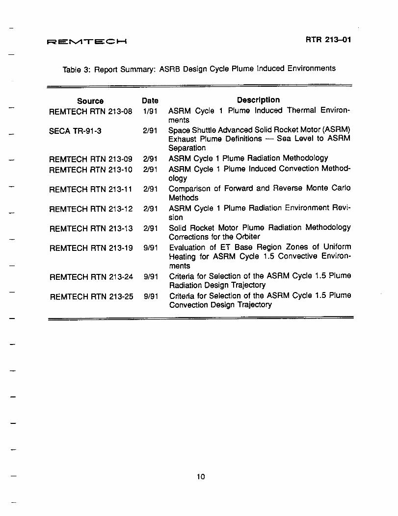
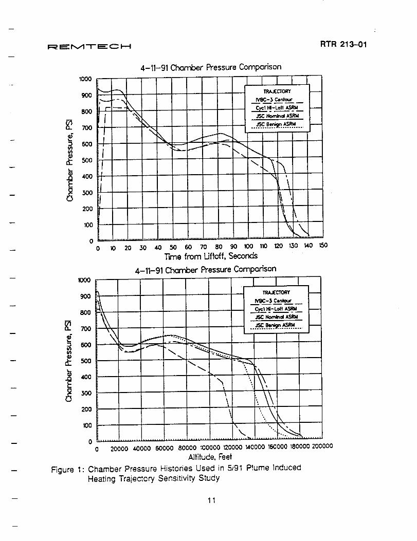
Since the release of the Cycle 1 environments, several studies have been performedto evaluate both the radiative and convective environment with regard to ASRB trajec-
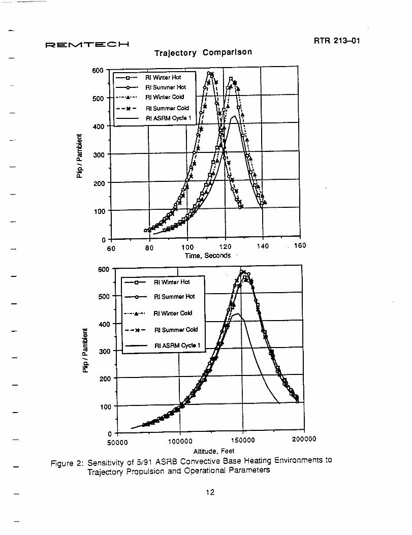
tory sensitivity [13,14]. Beginning in August 1991, JSC requested an evaluation of theradiation and convection environment impact of the nominal and benign ASRM trajecto-ries depicted in Fig. 1. As Fig. 2 exhibits, both the nominal and benign JSC trajectoriesdemonstrate convective heating as high or higher than the ASRM Cycle 1 High-Lofttrajectory; no significant increase in radiation was determined. However, this impact tothe convective environment was further explored in April 1991 using the RI hot/cold dis-persed, winter/summer launch, high-loft trajectories illustrated in Fig. 3. Figure 4 showsthat the high-loft, summer launch trajectory dispersed for a hot PMBT provides con-ditions conducive to a worse case convective heating environment. Likewise, low-loftwinter launch trajectory conditions produce the most conservative radiation heating envi-ronment. As a result, these conditions will be incorporated into the Cycle 1.5 convectiveenvironment trajectory.
Similar to Cycle 1 methodology development, preparations were initiated and arecontinuing for the Cycle 1.5 vintage environments. Convective environment zonespeculiar to the ET were defined and documented [15] in September 1991. Radiationmethodology is also maturing with the incorporation of MNASA and TEM test firing dataand prototype Monte Carlo code development.
9
RTR 213-01
developed and modified based on these flowfield definitions as they evolved according to the latest ASRB propellant and operating characteristics.
Cycle 1 radiation methodology [8-10] specifies for the radiation contribution resulting from the ASRBs to be based on the sea level RSRB plume model scaled to ASRB emissive powers - determined by making prediction of the ratio of emissions with the prototype Monte Carlo code [11]. The SSME radiation contribution utilized is the same as used in the IVBC-3 and Generic Certification environments. Similarly, the convective Cycle 1 methodology [12] was incorporated into a computer code. The SPICE (§.huttle Plume induced Convective Environment) code, which bases its computations on differences in chamber pressure and time/altitude history as compared with the Shuttle Centaur trajectory used to generate the IVBC-3 environments, was developed to generate the Cycle 1 convective environments in an IVBC-3 compatible format.
Cycle 1 methodology development culminated with the publication of the official ASRM plume induced environment package [6] in January 1991. Tabular environments were provided for a representative set of body points on the SRB, ET, Orbiter, and SSMEs. Normal (no-failure) ascent predictions using the Cycle 1 Low-Loft trajectory for radiation and the Cycle 1 High-Loft trajectory for convection were made for 118 body points. Ukewise, RTLS environments were determined for 29 body points for the Cycle 1 RTLS SSME 1 failure trajectory; 41 body points were evaluated assuming SSME 3 failure using the time/altitude data from the Cycle 1. RTLS trajectory and gimbal angles specified for Generic Certification RTLS.
Since the release of the Cycle 1 environments, several studies have been performed to evaluate both the radiative and convective environment with regard to ASRB trajectory sensitivity [13,14]. Beginning in August 1991, JSC requested an evaluation of the radiation and convection environment impact of the nominal and benign ASRM trajectories depicted in Fig. 1. As Fig. 2 exhibits, both the nominal and benign JSC trajectories demonstrate convective heating as high or higher than the ASRM Cycle 1 High-Loft trajectory; no significant increase in radiation was determined. However, this impact to the convective environment was further explored in April 1991 using the RI hoVcold dispersed, winter/summer launch, high-loft trajectories illustrated in Fig. 3. Figure 4 shows that the high-loft, summer launch trajectory dispersed for a hot PMBT provides conditions conducive to a worse case convective heating environment. Likewise, low-loft winter launch trajectory conditions produce the most conservative radiation heating environment. As a result, these conditions will be incorporated into the Cycle 1.5 convective environment trajectory.
Similar to Cycle 1 methodology development, preparations were initiated and are continuing for the Cycle 1.5 vintage environments. Convective environment zones peculiar to the ET were defined and documented [15] in September 1991. Radiation methodology is also maturing with the incorporation of MNASA and TEM test firing data and prototype Monte Carlo code development.
9
!:_ i_:- M T iz_" C I,,,-I RTR 213--01
Table 3: Report Summary: ASRB Design Cycle Plume Induced Environments
Source Date
REMTECH RTN 213-08 1/91
SECA TR-91-3 2/91
REMTECH RTN 213-09 2/91
REMTECH RTN 213-10 2/91
REMTECH RTN 213-11 2/91
REMTECH RTN 213-12 2/91
REMTECH RTN 213-13 2/91
REMTECH RTN 213-19 9/91
REMTECH RTN 213-24 9/91
REMTECH RTN 213-25 9/91
Description
ASRM Cycle 1 Plume Induced Thermal Environ-ments
Space Shuttle Advanced Solid Rocket Motor (ASRM)Exhaust Plume Definitions -- Sea Level to ASRM
Separation
ASRM Cycle 1 Plume Radiation Methodology
ASRM Cycle 1 Plume Induced Convection Method-ology
Comparison of Forward and Reverse Monte CarloMethods
ASRM Cycle 1 Plume Radiation Environment Revi-sion
Solid Rocket Motor Plume Radiation MethodologyCorrections for the Orbiter
Evaluation of ET Base Region Zones of UniformHeating for ASRM Cycle 1.5 Convective Environ-ments
Criteria for Selection of the ASRM Cycle 1.5 PlumeRadiation Design Trajectory
Criteria for Selection of the ASRM Cycle 1.5 PlumeConvection Design Trajectory
10
RTR 213-01
Table 3: Report Summary: ASRB Design Cycle Plume Induced Environments
Source REMTECH RTN 213-08
SECA TR-91-3
REMTECH RTN 213-09 REMTECH RTN 213-10
REMTECH RTN 213-11
REMTECH RTN 213-12
REMTECH RTN 213-13
REMTECH RTN 213-19
REMTECH RTN 213-24
REMTECH RTN 213-25
Date Description 1/91 ASRM Cycle 1 Plume Induced Thermal Environ
ments 2/91 Space Shuttle Advanced Solid Rocket Motor (ASRM)
Exhaust Plume Definitions - Sea Level to ASRM Separation
2/91 ASRM Cycle 1 Plume Radiation Methodology 2/91 ASRM Cycle 1 Plume Induced Convection Method
ology 2/91 Comparison of Forward and Reverse Monte Carlo
Methods 2/91 ASRM Cycle 1 Plume Radiation Environment Revi
sion 2/91 Solid Rocket Motor Plume Radiation Methodology
Corrections for the Orbiter 9/91 Evaluation of ET Base Region Zones of Uniform
Heating for ASRM Cycle 1.5 Convective Environments
9/91 Criteria for Selection of the ASRM Cycle 1.5 Plume Radiation Design Trajectory
9/91 Criteria for Selection of the ASRM Cycle 1.5 Plume Convection Design Trajectory
10
i:_ -,-,-,-,-,-,-,-,-,-_-M T ,,,,,,_--C i.,_!
1000
90O,-._.
8OO
If? _o i
,,I
!'°°13oo.i
200 _J
1000
9OO
800
D 6OO
3110
200
100
4-11-91 Chamber Pressure Comparison
I I { !
1'_-3 Centou¢
...._...e:..,_.....,_.......-_,
,-,_--_ ,,.,. -..._
[\
\|uiP°..., ..... ,, ..... _.l,, .,,==.,,, ,=, ............... i ......... _,LA,..,, ,=.°,,=.l,..°.°.o, ,.,,°., ...... , ..... .,..,,°,
so 4o 5o so To 8o 90 lOO 1_ 12o
Trne from Ufioff, Seconds
4-11-91 Chamber Pressure Comparison
_ .f--.\ -_-_
0 10 20 130140150
L•_ IRAJECTOR'¢
....-_...._...'_.._ .... J--
\
\ "\
\ ",.,.j
o 20000 4oooo 6oooo eoooo _coooo_oooo _oooo _ecooo_8oooo2oc0ooAlfifude,Feel
Figure 1" Chamber Pressure Histories Used in 5191 Plume Induced
Heating Trajectory Sensitivity Study
RTR 213-01
11
RTR 213-{)1
4-11-91 Chamber Pressure Comparison 1000
I 900
800
~ 700
~ :J 600 III III
~ SOO ~ Q)
400 -g .E 300 U
200
100
~ -- TR.U:CTORY t--1;--I- - ~
~ /V9C-l Centaur
II r ---_.-~~-Lolt~_ r--
I ,~
~ JSC NomInoI ASRW
'" JSC a,' ASRW f--: ~ .......... '!?! ..........
~ ~ ~ ~ , V ~- -."
~~ I ~
~
! " ~ t1 ~; ~
, \
I . \ ~ I
t\i
1~
" ~\. o o 10 20 30 40 50 60 70 80 90 100 110 120 130 140 150
Tme from Uftoff, Seconds 4-11-91 Charrber Pressure Comparison
1000
900 ~ TR.U:CTORY t--
800
~ 100
~ :J 600 III III
~ 500 ~ Q)
400
~ 300 U
200
100
~\ /V9C-l Centaur --.--.-
~ ~~-Loft~_ t--
JSC tbNIoI ASRW
.. ~.~~ .... r--\~ ~ ~ r-......
~-:=, ... ---t'-" ,.~
~ ~ -:--.. "- -~
""'- K\ '\ ~\ '\
\ .... 1\ \ \ .. \ f\ ,
~ ' ... o o 20000 40000 60000 80000 ~COOOO 120000 140000 160000 180000 200000
Altitude, Feet Figure 1: Chamber Pressure Histories Used in 5/91 Plume Induced
Heating Trajectory Sensitivity Study
11
I_ I=r M T I=" C I.,.. I
Trajectory Comparison
RTR 213-O1
O.
n
O,.
&O.
6OO
500
400
300
200
100 '"
140 160
li
---o-,- RI Winter Hot J/
- ----o--- RI Summer Hot
.... i'-" RI Winter Cold
--_1. - RI Summer Cold
--"------" RI _ Cycl Ib' \\
•X,X_"'i | • •
50000 100000 150000 200000
Altitude. Feet
Figure 2: Sensitivity of 5_91 ASRB Convective Base Heating Environments toTraje_ory Propulsion and Operational Parameters
12
RTR 21~1
Trajectory Comparison
600 - 0- AI Winter Hot
~ AI Summer Hot
500 _._ • .a,._. AI Winter Cold
--)t- Al Summer Cold
AI ASAM Cycle 1
400 C Q)
~ 300 cu a.. -0. .... a..
200
100+-------~--~~~~---+--~--~----~
0 60 80 100 120 140 160
Time, Seconds
600
--0- Al Winter Hot
500 ~ AI Summer Hot
_.- • .a,.-. AI Winter Cold
400 C --)t- Al Summer Cold Q)
~ AI ASRM Cycle 1 cu 300 a.. -0. := a..
200
100~------------~aF-----------+------~--~
O+-----~-----+----~~----+-----~----~
50000 100000 150000 200000
Altitude. Feet
Figure 2: Sensitivity of 5,91 ASRB Convective Base Heating Environments to
Trajectory Propulsion and Operational Parameters
12
i_=
"MT
'.="
CI--I
RT
R213-01
=0uoo0o.,000o-_,E
-
13
_0._>o
_¢/)¢=
03¢,-o
_CD
-1-
._>00=_cnc-o.¢.-mo.00o_I--
c_/-i
t_
OR
1G]N
AL
PA
QE
IS
OF
PO
OR
QU
AL
ITY
00
;~ 8~ ~r-
,0"'0 c» ~~ :;!Ui
...... w
Trajectory Comparison for June 18, 1991 Telecon
Sensitivity of ASRB Convective Base Heating Environments to Trajectory propulsion and Operational parameters
T, .J''''o,y P.,.m.'., 11·'2·90 4·11·9' 4-1'·9' 4-3-9' 4-3·9' 4-3·9' RJ CycItI , JSC JSC Loc:kh •• dlIuQ Loc:kh •• dlluQ Loc:kh •• dlluka
4-3·91 I
LocI<h.edlluka tligh Loll Nomln8I Benign flot, High Loll f/ot, Low Lolf Cold. High LcIt Cold, Low Lofr '
~ ~ ~
!,MO~F 64 (OtIC) 78 (July) 78 (July) 90 90 40 SI"Uinu .f1_Jhl PlAlh Angle· dag 24 29 29 32 26 32 M • .uilllulII OynOAlllic PU'~U'tI • P&' 819. 690 600 701 731 630 SI"UiIIlJ TUII" - .uc 141_4 133.3 133.3 131_5 131.5 138.7 ~~~ Ahlludll • kit 184 179 169 185 171 189 01l~1I1 uI PlulIIlI Rucilcullllion • ItIC 90.0 84.7 87.3 83.1 83.1 89.0 O,,:.ul-;;;;'luIIII. RucilculOAlion· kit 74 72 72 72 70 74 OI:'~I:.ion 3.~!". None None None None None
tor Cold ASRBs T ypicitl Coovttetlve Peak ttealing Ral. 1nCf .... ov.r 22.80 27.94 23.69 30.37 28.41 22.71
lVue J l;uviu"uIHlIll tAl aP l1OOO (ET Dom. ) -l' .. ,t;Vul
-Typic.ai Conv4lCtiYe Tolalloed loa .... ovelIVBC-3 2_43 3.52 3.56 1.47 8.39 -1.71 I:/lIIIIOIIIIIU.II.1 UP 8000 (ET (luIlIlI,- PII'OIflI
~ • JSC IIaj@ctories plovided by Curt Wloderttoefl; RI Cycle 1 HIgh Loft Trajectory provided by Doug Senert
• JSC trajectories baHd on guidelines plovlded In ASRM Normal Trajectory Design Data Package (TDDP ASRMA1); RI Cycle 1 II "j~y baiud on piujninary vefiion 01 TDOP ASRAMA 1
• ChaotJe, plussure hl&tory RlOiI altecled by PUBT; RSRM baselne PMBT - 70 deg F, whereas ASRM baselne PMBT - 60 deg F
- Rl's 3-sigma ospersion tor cold SRBllnvoIves multiplying lime lable by 1.049. then dividing flow rates and charmer pressure by 1.049---uUuClivuly lnCIuaslng bum lime
- AI', high bn ait8Aa Involves Cleating I 3-&Igma high change In altllUde approximately 10 seconds before staging
Figure 3: 8/91 Trajectory Comparisons Used in Convective Heating Sensitivity Study
40 26
656 138.7 175 89.0 72
None
20.79
4.66
:u m ~ -I PI o I
:D -I :D I\) ~
b ~
I_=
"M
"T"
Eq3
I--!R
TR
213.-01
•.:_
"_"=
_
,,,.:_o
=,..,..°.°
'_
!I",,.
_oo<
,',_.,:o.-..-_oo=
o,..
!=o
<',","=
_o.>=<
.,,,>=
<,,->
,i
o=
1_,,_1_1<
_Iol0";1_:,,,n
.,.-_,o
(3°_
;NN
_,_r¢l
=r..=
=m
lI,-.
m¢>
EE
__..-,..,_
..-.._,_
_,,_,
_a2
_>"<"
o_
==@-i==
_-=_-,
-<
,,°1"'
:©1
ml"_l_
Iml°'
n"
|I'_
II|=
II
O'li
'i'--|_l%
ll_
'__l
i,fi¢_
_0
_I'-'
l"lI'-
|_-
om
_I_;=I=I,,.I_
_!.
'_'
_,I,--_,I,,Io,
I__
"__
<.,..<
,oo,-
Z=_-I--.--I'--I--I
--_
_o
_•,-o
or--
__
•,-.-.o
©=
-rot,-
=lm
lml
==
!m:::3
m
,=,.__
"6•"I_"
_'1_1(_!0h
!_..
=.
"o.=-6o
@=.,"_
--_=
,,¢.=
.¢.=
,,r-.-'l
I.l.
0Z
14
Body Point Locations
Shuttle Component Body Point Location/Description ASRB 2116 Aft Skirt
11104 Kick Rina Web TPS ET 8000 Aft Dome (Zone 2)
8670 Aft Dome. (Zone 1)
8-20-91 RI ASRM Trajectory Comparison
ASRM Trajector
-4
.J:>.
Body Cycle 1 Summer Summer Winter Point High-Loft Cold Disp. Hot Dlsp • Cold DlsD.
2116 ~eak Rate: 6.35 (114.95) 6.98 (126.48) 7.03 (127.49) 6.39 (115.82) Total Load: 151.29 (113.56) 148.12 (111.18) 152.19 (114.24) 144.41 (108.40)
11104 Peak Rate: 8.86 (116.03) 9.69 (126.86) 9.83 (128.77) 8.91 (116.62)
Total Load: 182.52 (105.51) 177.98 (102.88) 182.97 (105.77) 173.90 (100.52)
8000 Peak Rate: 8.65 (122.80) 9.35 (132.76) 9.53 (135.37) 8.60 (122.14) -iotal Load: 199.62 (102.43) 194.58 (99.84) 197.26 (101.21) 190.38 (97.69)
8670 Peak Rate: 9.84 (123.04) 10.82 (135.23) 10.98 (137.27) 9.90 (123.78)
Total Load: 224.87 (99.71) 217.87 (96.61) 221.04 (98.02) 213.37 (94.62)
Notes: 1) Heating rates and loads are based on T wall = 540 R
2) Units for peak heating rates are BTU/Ft2·Sec; total heat load are BTUIFt2
3) Value in parentheses indicate percent of IVBC-3 operational environment
Figure 4: Summary of Convective Results for 8/20/91 Trajectory Sensitivity Study
Winter Hot DlsD. 6.48 (117.44)
147.73 (110.89)
9.05 (118.48)
177.90 (102.83)
8.76 (124.40)
193.70 (99.39)
10.06 (125.75)
216.99 (96.22)
I
i
lJ PI ~ -I 111
o I
:0 -i :0 N ~
b ~
i=_ iE M .-i- r.-.==-C i--.i RTR 213-01
2.3 ASRB DFI Planning and Coordination
REMTECH became involved with Development Flight Instrumentation (DFI) in July1990. At that time REMTECH was asked to develop a list of instrumentation for theAdvanced Solid Rocket Boosters which is necessary to perform their mission. This
original list, consisting of 104 gages, was combined with requests from USBI, Aerojet,and Rockwell to form a complete list of thermal DFI This complete list was then examinedfor overlapping requests. After the duplicate requests were eliminated, the list was stilllarger than could be accommodated by the proposed data system on the ASRBs. Effortswere then directed toward scrubbing the requests to a level that can be accommodated
by the proposed data system. Several iterations were performed where instruments wereprioritized and scrubbed by the individual requestors. Since this caused no significantreduction in the number of gages requested, meetings were held with the ASRB andASRM Chief Engineers so that requestors could justify each gage being requested. TheChief Engineer then decided if the justification warranted the instrumentation requested.
This reduced the number of gages requested, but was not sufficient in the case of thethermal DFI to be accommodated by the proposed data system. The major result of these
presentations was the Chief Engineers' awareness of the inadequacy of the proposeddata system, particularly in the area of the analog channels required for thermal DFI.As a result, two flight configurations for three flights each are being considered insteadof the one flight configuration for six flights originally proposed. This will allow for morevaried flight data to be obtained even though the number of flights may be reduced ata particular data location. The last list submitted to USBI for integration indicated thethermal DFI gages requested and the desired flight configuration for each gage.
MSFC/ED33 also requested that REMTECH become involved with the selectionof the DFI for the Orbiter, External Tank, and Space Shuttle Main Engines (SSMEs)through our involvement with the Thermal Panel. The Thermal Panel requested thatREMTECH keep them abreast of the thermal DFI on the ASRBs in the biweekly telecons.As the thermal DFI on the other elements evolved similar to the instrumentation on
the ASRBs, REMTECH became the collection and integration point for the various
requests. This resulted in REMTECH preparing justification and rationale charts forall elements using the same format that was used for the presentations to the ASRB andASRM Chief Engineers. These charts were reviewed with Level II Shuttle integrationmanagement. REMTECH is the integration focal point for thermal DFI on all elements andhas maintained the "official" list for the Thermal Panel. Additional work was performed
by REMTECH in the form of charts, tables, and viewgraphs to support presentationsgiven by Level II.
Two technical notes were also written as a part of REMTECH's DFI effort. The first
technical note [16] documents a sensitivity study that was undertaken at the requestof the ASRB Chief Engineer. This study looked at the effect of reducing the numberof pressure measurements on the circumference of the Forward Motor Segment onthe accuracy of the data. It was determined that 12 gages was the minimum numberof pressure readings required to keep the percent error at an acceptable level. The
15
RTR 213-01
2.3 ASRB OFI Planning and Coordination REMTECH became involved with Development Flight Instrumentation (OFI) in July
1990. At that time REMTECH was asked to develop a list of instrumentation for the Advanced Solid Rocket Boosters which is necessary to perform their mission. This original list, consisting of 104 gages, was combined with requests from USBI, Aerojet, and Rockwell to form a complete list of thermal OFI This complete list was then examined for overlapping requests. After the duplicate requests were eliminated, the list was still larger than could be accommodated by the proposed data system on the ASRBs. Efforts were then directed toward scrubbing the requests to a level that can be accommodated by the proposed data system. Several iterations were performed where instruments were prioritized and scrubbed by the individual requestors. Since this caused no significant reduction in the number of gages requested, meetings were held with the ASRB and ASRM Chief Engineers so that requestors could justify each gage being requested. The Chief Engineer then decided if the justification warranted the instrumentation requested.
This reduced the number of gages requested, but was not sufficient in the case of the thermal OFI to be accommodated by the proposed data system. The major result of these presentations was the Chief Engineers' awareness of the inadequacy of the proposed data system, particularly in the area of the analog channels required for thermal OFI. As a result, two flight configurations for three flights' each are being considered instead of the one flight configuration for six flights originally proposed. This will allow for more varied flight data to be obtained even though the number of flights may be reduced at a particular data location. The last list submitted to USBI for integration indicated the thermal OFI gages requested and the desired flight configuration for each gage.
MSFC/E033 also requested that REMTECH become involved with the selection of the OFI for the Orbiter, External Tank, and Space Shuttle Main Engines (SSMEs) through our involvement with the Thermal Panel. The Thermal Panel requested that REMTECH keep them abreast of the thermal OFI on the ASRBs in the biweekJy telecons. As the thermal OFI on the other elements evolved similar to the instrumentation on the ASRBs, REMTECH became the collection and integration point for the various requests. This resulted in REMTECH preparing justification and rationale charts for all elements using the same format that was used for the presentations to the ASRB and ASRM Chief Engineers. These charts were reviewed with Level II Shuttle integration management. REMTECH is the integration focal point for thermal OFI on all elements and has maintained the "official" list for the Thermal Panel. Additional work was performed by REMTECH in the form of charts, tables, and viewgraphs to support presentations given by Level II.
Two technical notes were also written as a part of REMTECH's OFI effort. The first technical note [16] documents a sensitivity study that was undertaken at the request of the ASRB Chief Engineer. This study looked at the effect of reducing the number of pressure measurements on the circumference of the Forward Motor Segment on the accuracy of the data. It was determined that 12 gages was the minimum number of pressure readings required to keep the percent error at an acceptable level. The
15
I_ I_M TI_ C !'--! RTR 213-01
second technical note [17] documents the installation requirements for each proposedREMTECH Gas Temperature Probe (GTP) location. The REMTECH GTP was originallydesigned to be flown at a specific location on the Orbiter only. Current plans call forfive GTP's to fly on each Development Flight; two on the right ASRB, two on the ET,and one on the Orbiter.
A summary of the reports prepared under this contract effort pertinent to DFI ispresented in Table 4.
Table 4: Report Summary: ASRB DFI Planning and Coordination
Source Date
REMTECH RTN 213-5-01 8/91
REMTECH RTN 213-22 9/91
Description
Evaluation of the Number of Pressure Ports
Required for Prediction of Peak Impact Pres-sure and Roll Orientation of the SRB DuringReentry
REMTECH Gas Temperature Probe Instal-
lation Requirements for ASRB DevelopmentFlights
2.4 ASRB Thermal Panel Support
The ASRB Thermal Panel is comprised of representatives from NASA's JSC andMSFC centers, plus Shuttle element and integration contractor teams. The panel ischaired by JSC organization EG3 and has a mandate to coordinate and approve Shuttlewith ASRB technical issues in the general technical discipline of aerothermodynamicsand induced thermal environments. MSFC organization ED33 is an integral part of thepanel, and REMTECH, as a major ASRB contractor to ED33, has been a participatingpanel member since the panel's inception after the ASRB contract go-ahead.
Throughout the 22-month history of our ASRB contract, REM'I'ECH has providedkey inputs to the Thermal Panel, pdmadly to support the discussion and resolution ofissues which were addressed in biweekly teleconferences. Many of these inputs wereprepared in viewgraph summary format with supporting tabular and graphical data asnecessary to augment the text. Typical issues which have been addressed include:
1. Overviews of base heating methodology.2. Summaries of solid rocket motor subscale test objectives, procedures, and recorded
data.
3. Guidelines, assumptions, and schedules for design cycle environment packages.4. Justification for ASRB DFI for all elements.
5. Specific technical issues such as trajectory effects on convective base heating.
16
RTR 213-01
second technical note [17] documents the installation requirements for each proposed REMTECH Gas Temperature Probe (GTP) location. The REMTECH GTP was originally designed to be flown at a specific location on the Orbiter only. Current plans eall for five GTP's to fly on each Development Flight; two on the right ASRB, two on the ET, and one on the Orbiter.
A summary of the reports prepared under this contract effort pertinent to DFI is presented in Table 4.
Table 4: Report Summary: ASRB DFI Planning and Coordination
Source REMTECH RTN 213-5-01
REMTECH RTN 213-22
Date 8/91
9/91
Description Evaluation of the Number of Pressure Ports Required for Prediction of Peak Impact Pressure and Roll Orientation of the SRB During Reentry REMTECH Gas Temperature Probe Installation Requirements for ASRB Development Flights
2.4 ASRB Thermal Panel Support
The ASRB Thermal Panel is comprised of representatives from NASA's JSC and MSFC centers, plus Shuttle element and integration contractor teams. The panel is chaired by JSC organization EG3 and has a mandate to coordinate and approve Shuttle with ASRB technical issues in the general technical discipline of aerothermodynamics and induced thermal environments. MSFC organization ED33 is an integral part of the panel, and REMTECH, as a major ASRB contractor to ED33, has been a participating panel member since the panel's inception after the ASRB contract go-ahead.
Throughout the 22-month history of our ASRB contract, REMTECH has provided key inputs to the Thermal Panel, primarily to support the discussion and resolution of issues which were addressed in biweekly teleconferences. Many of these inputs were prepared in viewgraph summary format with supporting tabular and graphical data as necessary to augment the text. Typical issues which have been addressed include:
1. Overviews of base heating methodology. 2. Summaries of solid rocket motor subseale test objectives, procedures, and recorded
data. 3. Guidelines, assumptions, and schedules for design cycle environment packages. 4. Justification for ASRB DFI for all elements. 5. Specific technical issues such as trajectory effects on convective base heating.
16
I_ I_ M T I=" C I---I RTR 213-01
6. Discussion of relevant code capabilities, including the SIRRM and Monte Carlo plumeradiation codes.
7. Body point selection for design environments.8. Variety of subissues related to issues 1 through 7.
An example of one typical panel discussion input from REMTECH is provided inFigs. 5 through 9.
17
RTR 213-01
6. Discussion of relevant code capabilities, including the SIRRM and Monte Carlo plume radiation codes.
7. Body point selection for design environments. 8. Variety of subissues related to issues 1 through 7.
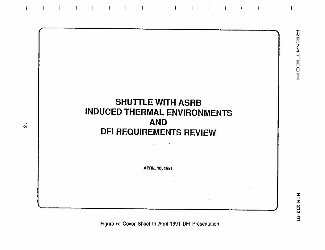
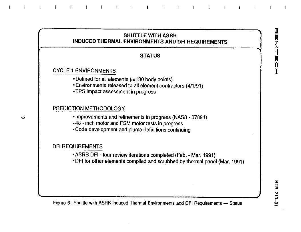
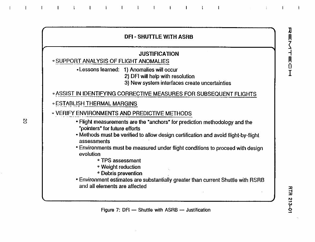
An example of one typical panel discussion input from REMTECH is provided in Figs. 5 through 9.
17
I:_E
I'v'l"-r
EC
I---!
=,,=,
_In.,rr-
tu_0
_!,,-IL
l
U.I
--0
u_
Z
18
cr,,,,ime_
RT
R213-01
t--0°_(..-G
)(;1
0..
LI..C
3
O_
O_
u°_C_
0,e..,=
0G)
¢,,-03t==,
0°_U..
r
-... co
SHUTTLE WITH ASRB INDUCED THERMAL ENVIRONMENTS
AND OFI REQUIREMENTS REVIEW
APRIL 10, 1991
Figure 5: Cover Sheet to April 1991 OFI Presentation
~
~
lJ III
~ , III o I
:tJ -i :tJ N ...a.
b ...a.
I_E
MT
EC
i,---IR
TR
213-01
i
ZIll
I.I.I
0l.U
u.
Ill
..I
Ill
"r
tU
ZI
Ie.-
Eo_IU.Ee-£o_e-
WEe-I--
enGOe-e-
u_
19
SHUTTLE WITH ASRB INDUCED THERMAL ENVIRONMENTS AND DFI REQUIREMENTS
STATUS
CYCLE 1 ENVIRONMENTS
-Defined for all elements (~130 body points) - Environments released to all element contractors (4/1/91) -TPS impact assessment in progress
PREDICTION METHODOLOGY ~
<0 -Improvements and refinements in progress (NAS8 - 37891) -48 - inch motor and FSM motor tests in progress -Code development and plume definit,ions continuing
DFI REQUIREMENTS --------
-ASRB DFI - four review iterations completed (Feb. - Mar. 1991) - DFI for other elements compiled and scrl:Jbbed by thermal panel (Mar. 1991)
Figure 6: Shuttle with ASRB Induced Thermal Environments and OFI Requirements - Status
..J
;u m ~ 1 m o I
:D -t :D N ....a.
b ....a.
i::_!_--
M.-T
-i==-C
i-.I
RT
R213-01
t-
.o
.o
°_Io')<t-(9
U3It.L.
°_U.
2ON o
, DFI - SHUTTLE WITH ASRB
JUSTIFICATION o SUPPORT ANALYSIS OF FLIGHT ANOMALIES
• Lessons learned: 1) Anomalies will occur 2) DFI will help with resolution 3) New system interfaces create uncertainties
o ASSIST IN IDENTIFYING CORRECTIVE MEASURES FOR SUBSEQUENT FLIGHTS ~ -._------
o ESTABLISH THERMAL MARGINS
u VERIFY ENVIRONMENTS AND PREDICTIVE METHODS
• Flight measurements are the "anchors" for prediction methodology and the "pointers" for future efforts
• Methods must be verified to allow design certification and avoid flight-by-flight assessments .
• Environments must be measured under flight conditions to proceed with design evolution
o TPS assessment o Weight reduction o Debris prevention .
• Environment estimates are substantially greater than current Shuttle with RSRB and all elements are affected
Figure 7: OFI - Shuttle with ASRB - Justification
..J
;u m ~ -1 m o I
::D -i ::D N -4
b -4
I_,=
"M
T=
"O
I..-.-IR
TR
213-01
I_z
0(J00I<e-
me.-Ie-
mmU.0or)
ffl
8zU-
21
/'
I\) -L
NECESSITY OF OFI FOR INITIAL FLIGHTS -SHUTTLE WITH ASRB
CONCLUSIONS
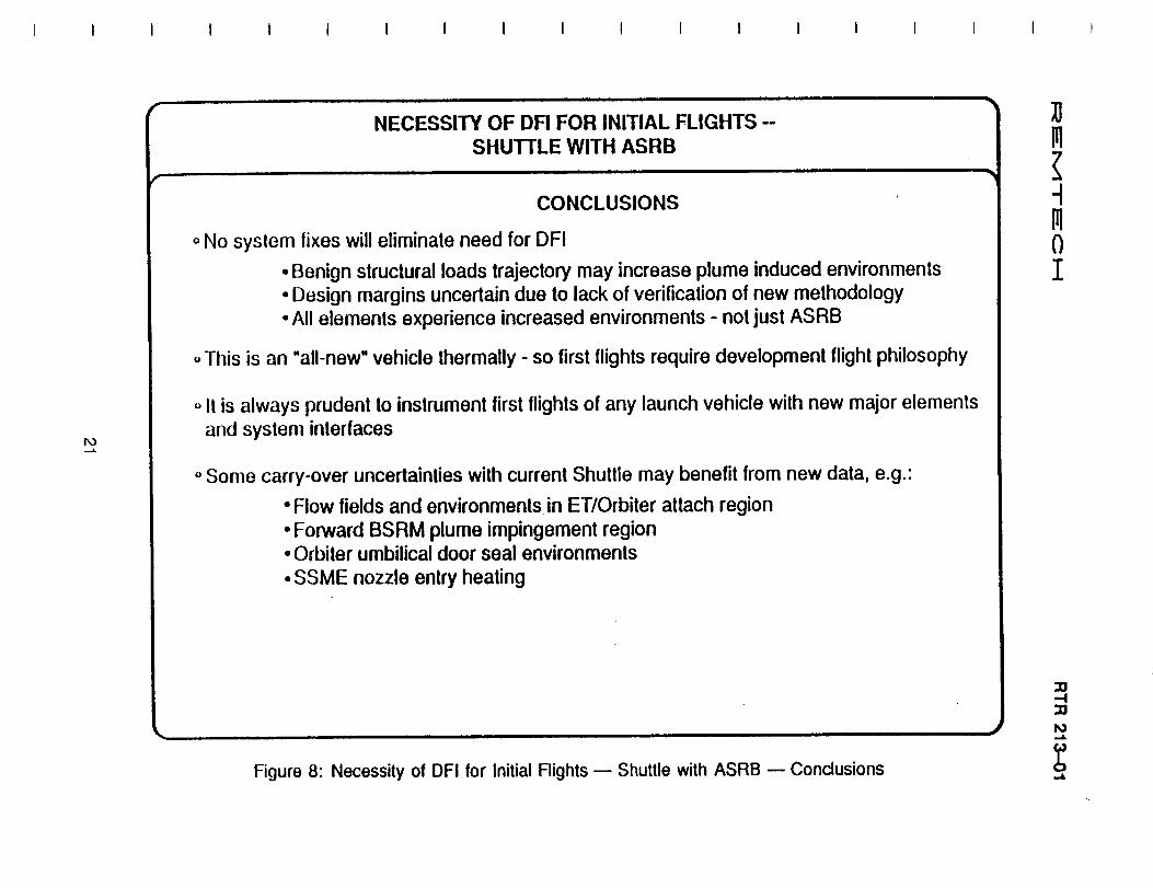
o No system fixes will eliminate need for OFI
• Benign structural loads trajectory may increase plume induced environments • Design margins uncertain due to lack of verification of new methodology • All elements experience increased environments - not just ASRB
u This is an "all-new" vehicle thermally - so first flights require development flight philosophy
o It is always prudent to instrument first flights of any launch vehicle with new major elements and system interfaces
o Some carry-over uncertainties with current Shuttle may benefit from new data, e.g.:
• Flow fields and environments in ET/Orbiter attach region • Forward BSRM plume impingement region • Orbiter umbilical door seal environments • SSME nozzle entry heating
Figure 8: Necessity of OFI for Initial Flights - Shuttle with ASRB - Conclusions
~
;u m ~ -1 m o I
:IJ -f :IJ N ~
b ~

i:_E
MT
EC
:;I--I
RT
R213-01
mlmI
ii
.e-
0..-,
xx.__mxx
"_'ID
Q,.
"_
"¢:J
0(I::l
..--'....,',--
",,=,,'.-'
,...-'
EE
=c_EE
'_"_-
_-_._._s_._,_
E==_'8
xc__
-_.._
,_
-'-"_..-
_._
_
-,-m_,a_
N_/
__=_=
=_,=
_o.-_-o._--
I==
_.-=
=_
LL
Im
--_<
<rj}
C:::
7_cj
_rr':
g_og_eWi
22
N N
/"
INDUCED THERMAL ENVIRONMENTS .. SHUTTLE WITH ASRB
SUMMARY
ENVIRONMENTS DIFFERENT THAN SHUTILE WITH RSRB
• ASRB has: 1) Different exhaust thermochemistry due to higher aluminum content (19%)
2) Higher chamber pressure final 60 seconds of ascent 3) Shock impingement shift 4) Longer burn time and higher separation altitude 5) Different staging dynamics 6) More severe reentry trajectory
CYCLE 1 ENVIRONMENTS COMPARED WITH IVBC-3 DESIGN - - --, - --------fOR~-!~ITLE WITH RSRB
• Ascent base heating .Ascent aeroheating .Separation plume impingement
• Reentry aerohealing ~nternal aft skirt
(Estimated 1.3 x RSRB) (Estimated 1.1 x RSRB) (Analysis pending availability of separation trajectory) (Estimated 1.5 x RSRB) (Estimated 1.8 x RSRB)
Figure 9: Induced Thermal Environments - Shuttle with ASRM - Summary
~ ~ m ~ 1 m o I
:D -i :D N -I.
b -I.
I_ EEM -T'EE C I_1 RTR 213-01
[1]
[2]
[3]
[4]
[5]
[6]
[7]
[8]
[9]
[lO]
[11]
[12]
[13]
[14]
[15]
[16]
Section 3REFERENCES
Reardon, J. E., "Plume Radiation Measurements for the 48-inch RSRM and ASRMMotor Tests," REMTECH Report RTN 213-04, April 9, 1990.Reardon, J. E. and Everson, J. "Evaluation of Radiation Measurements on the
MNSASA-3 Motor Test," REMTECH Report RTN 213-18, June 18, 1991.Reardon, J. E. and Reardon, C. G. "Radiation Measurements on the TEM-7 Test
of the Space Shuttle Solid Rocket Motor," REMTECH Report RTN 213-20, July31, 1991.
Reardon, J. E. "Preliminary Plume Radiation Measurement Requirements for theASRM Development Firings at Stennis Space Center," REMTECH Report RTN213-06, Oct. 16, 1990.Reardon, J. E. "Preliminary Radiation Measurement Requirements for the StaticFiring of the Advanced Solid Rocket (ASRM) Motor," REMTECH Report RTN 213-17, June 13, 1991.Bender, R. L. and Reardon, J. E., "ASRM Cycle 1 Plume Induced Thermal Envi-ronments," REMTECH Report RTN 213-08, Jan. 21, 1991.
Smith, Sheldon D., "Space Shuttle Advanced Solid Rocket Motor (ASRM) ExhaustPlume Definitions -- Sea Level to ASRM Separation," SECA Report TR-91-3, Feb.1991.
Reardon, J. E., "ASRM Cycle 1 Plume Radiation Methodology," REMTECH ReportRTN 213-09, Feb. 1991.
Reardon, J. E., "ASRM Cycle 1 Plume Radiation Environment Revision," REMTECHReport RTN 213-12, Feb. 28, 1991.Reardon, J. E., "Solid Rocket Motor Plume Radiation Methodology Corrections forthe Orbiter," REMTECH Report RTN 213-13, Feb. 8, 1991.
Everson, John, "Comparison of Forward and Reverse Monte Carlo Methods,"REMTECH Report RTN 213--11, Feb. 1991.Bender, R. L. and Brown, J. R., "ASRM Cycle 1 Plume Induced Convection
Methodology," REMTECH Report RTN 213-10, Feb. 1991.Reardon, J. E., "Criteria for Selection of the ASRM Cycle 1.5 Plume RadiationDesign Trajectory," REMTECH Report RTN 213-24, Sep. 30, 1991.Reardon, J. E., "Criteria for Selection of the ASRM Cycle 1.5 Plume ConvectionDesign Trajectory," REMTECH Report RTN 213-25, Sep. 30, 1991.Bender, R. L. and Brown, J. R., "Evaluation of ET Base Region Zones of UniformHeating for ASRM Cycle 1.5 Convective Environments," REMTECH Report RTN213-19, Sep. 23, 1991.
Palko, Richard L., "Evaluation of the Number of Pressure Ports Required for Pre-diction of Peak Impact Pressure and Roll Orientation of the SRB During Reentry,"REMTECH Report RTN 213-5-01, August 1991.
23
Section 3 REFERENCES
RTR 213-01
[1] Reardon. J. E .• "Plume Radiation Measurements for the 48-inch RSRM and ASRM Motor Tests." REMTECH Report RTN 213-04. April 9, 1990.
[2] Reardon, J. E. and Everson, J. "Evaluation of Radiation Measurements on the MNSASA-3 Motor Test," REMTECH Report RTN 213-18, June 18, 1991.
[3] Reardon, J. E. and Reardon, C. G. "Radiation Measurements on the TEM-7 Test of the Space Shuttle Solid Rocket Motor," REMTECH Report RTN 213-20, July 31, 1991.
[4] Reardon, J. E. "Preliminary Plume Radiation Measurement Requirements for the ASRM Development Firings at Stennis Space Center," REMTECH Report RTN 213-06, Oct. 16, 1990.
[5] Reardon, J. E. "Preliminary Radiation Measurement Requirements for the Static Firing of the Advanced Solid Rocket (ASRM) Motor," REMTECH Report RTN 213-17, June 13, 1991.
[6] Bender, R. L. and Reardon, J. E., "ASRM Cycle 1 Plume Induced Thermal Environments," REMTECH Report RTN 213-08, Jan. 21, 1991.
[7] Smith, Sheldon D., "Space Shuttle Advanced Solid Rocket Motor (ASRM) Exhaust Plume Definitions - Sea Level to ASRM Separation," SECA Report TR-91-3, Feb. 1991.
[8] Reardon, J. E., "ASRM Cycle 1 Plume Radiation Methodology," REMTECH Report RTN 213-09, Feb. 1991.
[9] Reardon, J. E., "ASRM Cycle 1 Plume Radiation Environment Revision," REMTECH Report RTN 213-12, Feb. 28, 1991.
[10] Reardon, J. E., "Solid Rocket Motor Plume Radiation Methodology Corrections for the Orbiter," REMTECH Report RTN 213-13, Feb. 8, 1991.
[11] Everson, John, "Comparison of Forward and Reverse Monte Carlo Methods," REMTECH Report RTN 213-11, Feb. 1991.
[12] Bender, R. L. and Brown, J. R., "ASRM Cycle 1 Plume Induced Convection Methodology," REMTECH Report RTN 213-10, Feb. 1991.
[13] Reardon, J. E., "Criteria for Selection of the ASRM Cycle 1.5 Plume Radiation Design Trajectory," REMTECH Report RTN 213-24, Sep. 30, 1991.
[14] Reardon, J. E., "Criteria for Selection of the ASRM Cycle 1.5 Plume Convection Design Trajectory," REMTECH Report RTN 213-25, Sep. 30, 1991.
[15] Bender, R. L. and Brown, J. R., "Evaluation of ET Base Region Zones of Uniform Heating for ASRM Cycle 1.5 Convective Environments," REMTECH Report RTN 213-19, Sep. 23,1991.
[16] Palko, Richard L., "Evaluation of the Number of Pressure Ports Required for Prediction of Peak Impact Pressure and Roll Orientation of the SRB During Reentry," REMTECH Report RTN 213-5-01, August 1991.
23
I_ I:_" M T E C i.--.I RTR 213-01
[17] Palko, Richard L., "REMTECH Gas Temperature Probe Installation Requirementsfor ASRB Development Flights," REMTECH Report RTN 213-22, Sep. 17, 1991.
24
RTR 213-01
[17] Palko, Richard L., "REMTECH Gas Temperature Probe Installation Requirements for ASRB Development Flights," REMTECH Report RTN 213-22, Sep. 17, 1991.
24