R&S®BTC Broadcast Test Center - livingston … · Version 01.01, June 2013 Rohde & Schwarz...
56
Broadcasting Data Sheet | 01.01 R&S®BTC Broadcast Test Center Specifications
Transcript of R&S®BTC Broadcast Test Center - livingston … · Version 01.01, June 2013 Rohde & Schwarz...
Br
oadc
astin
g
Data
She
et |
01.0
1R&S®BTCBroadcast Test CenterSpecifications
BTC_dat-sw_en_3606-8550-22_v0200_cover.indd 1 13.06.2013 12:51:58
Version 01.01, June 2013
2 Rohde & Schwarz R&S®BTC Broadcast Test Center
CONTENTS Definitions ....................................................................................................................................................................... 5 Frequency and baseband main module options .......................................................................................................... 6
Frequency options .................................................................................................................................................................................. 6 Baseband main module options .............................................................................................................................................................. 6
Enhancement options ..................................................................................................................................................... 6 RF characteristics ........................................................................................................................................................... 7
Frequency ............................................................................................................................................................................................... 7 Frequency sweep .................................................................................................................................................................................... 7 Reference frequency ............................................................................................................................................................................... 7 Level ....................................................................................................................................................................................................... 8 Level sweep ............................................................................................................................................................................................ 8 Spectral purity ......................................................................................................................................................................................... 9 Phase coherence .................................................................................................................................................................................. 11
I/Q modulation ............................................................................................................................................................... 12 I/Q modulation performance ................................................................................................................................................................. 12 Analog I/Q inputs .................................................................................................................................................................................. 13 Internal baseband characteristics (R&S®BTC-B11 or R&S®BTC-B12 option) ...................................................................................... 14 Analog I/Q outputs ................................................................................................................................................................................ 14 Differential analog I/Q outputs .............................................................................................................................................................. 15 Digital baseband inputs/outputs (R&S®BTC-B1 or R&S®BTC-B2 option and R&S®BTC-K2500 option) .............................................. 15
Digital audio/video ........................................................................................................................................................ 17 Internal test signals ............................................................................................................................................................................... 17 Digital audio/video interfaces ................................................................................................................................................................ 17
TS serial interface ............................................................................................................................................................................. 17 IP coder interface .............................................................................................................................................................................. 18
Multimedia generator suite (R&S®BTC-K20 option).............................................................................................................................. 18 Transport stream generation (in preparation) .................................................................................................................................... 18 Bitstream player ................................................................................................................................................................................ 18 Stream libraries (R&S®LIB-Kxx options)............................................................................................................................................ 19 Bitstream recorder (in preparation) ................................................................................................................................................... 19
Broadcast multiplexer ........................................................................................................................................................................... 19 DVB/ATSC multiplexer (in preparation) ............................................................................................................................................. 19
Realtime gateway ................................................................................................................................................................................. 20 T2-MI multiprofile gateway (R&S®BTC-K24 option) .......................................................................................................................... 20
Error injection ........................................................................................................................................................................................ 21 MPEG-2 transport stream error injection ........................................................................................................................................... 21
Version 01.01, June 2013
Rohde & Schwarz R&S®BTC Broadcast Test Center 3
Analog audio/video ....................................................................................................................................................... 21 Audio player .......................................................................................................................................................................................... 21 Audio signal generator .......................................................................................................................................................................... 21 Video signal generator .......................................................................................................................................................................... 22 Analog video library (R&S®LIB-K50 option) .......................................................................................................................................... 23
Digital modulation systems ......................................................................................................................................... 24 Terrestrial standards ............................................................................................................................................................................. 24
DVB-T2 (R&S®BTC-K516 option) ...................................................................................................................................................... 24 DVB-T/DVB-H (R&S®BTC-K501 option) ........................................................................................................................................... 25 T-DMB/DAB (R&S®BTC-K511 option) ............................................................................................................................................... 26 ATSC 8VSB, ATSC-M/H (R&S®BTC-K518 option) ........................................................................................................................... 26 DTMB (R&S®BTC-K512 option) ........................................................................................................................................................ 26 ISDB-T/ISDB-TB/ISDB-TSB (R&S®BTC-K506 option) ........................................................................................................................ 27 ISDB-Tmm (R&S®BTC-K506 option; in preparation) ........................................................................................................................ 27
Cable standards .................................................................................................................................................................................... 28 DVB-C2 (R&S®BTC-K517 option) ..................................................................................................................................................... 28 J.83/A/B/C coder (DVB-C, US Cable, ISDB-C; R&S®BTC-K502 option) .......................................................................................... 29
Satellite standards ................................................................................................................................................................................ 30 DVB-S/DVB-S2/DVB-DSNG (R&S®BTC-K508 option) ..................................................................................................................... 30 DIRECTV legacy modulation (R&S®BTC-K509 option) .................................................................................................................... 31
Analog modulation systems ........................................................................................................................................ 32 AM/FM/RDS (R&S®BTC-K570 option) .................................................................................................................................................. 32 Analog TV (R&S®BTC-K595 option) ..................................................................................................................................................... 34
Standard B/G (R&S®BTC-K595 option) ............................................................................................................................................ 34 Standard D/K (R&S®BTC-K595 option) ............................................................................................................................................. 35 Standard I (R&S®BTC-K595 option) .................................................................................................................................................. 35 Standard M/N (R&S®BTC-K595 option) ............................................................................................................................................ 36 Standard L (R&S®BTC-K595 option) ................................................................................................................................................. 36
Simulation ...................................................................................................................................................................... 37 Arbitrary waveform generator (R&S®BTC-K35 option) ......................................................................................................................... 37 Interferer management ......................................................................................................................................................................... 38 Distortion simulation and nonlinearity (R&S®BTC-K1200) .................................................................................................................... 38
TX distortion simulation ..................................................................................................................................................................... 38 RX distortion simulation (in preparation) ........................................................................................................................................... 38 IMUX/OMUX simulation (in preparation) ........................................................................................................................................... 39
Fading simulator (R&S®BTC-B1031, R&S®BTC-B1032 and R&S®BTC-B1034 options) ...................................................................... 39 Dynamic fading (R&S®BTC-K1031 option; in preparation) ............................................................................................................... 40 Extended statistic functions (R&S®BTC-K1032 option) ..................................................................................................................... 41 MIMO fading (R&S®BTC-K1034 option; in preparation) .................................................................................................................... 41

Version 01.01, June 2013
4 Rohde & Schwarz R&S®BTC Broadcast Test Center
Additive white Gaussian noise (AWGN; R&S®BTC-K1040 option) ....................................................................................................... 42 Extended noise generator (R&S®BTC-K1043 option) ........................................................................................................................... 42
Impulsive noise .................................................................................................................................................................................. 42 Phase noise ....................................................................................................................................................................................... 43
Analysis ......................................................................................................................................................................... 46 TS analyzer (in preparation) ................................................................................................................................................................. 46 BER measurements (R&S®BTC-K2060 option) .................................................................................................................................... 46 Analyzer modules ................................................................................................................................................................................. 47
MHL™ RX/TX (R&S®VT-B2350 option) ............................................................................................................................................ 47 MHL™ RX/TX (R&S®VT-B2351 option) ............................................................................................................................................ 47 HDMI™ RX 225 MHz (R&S®VT-B2360 option) ................................................................................................................................. 47 HDMI™ RX 300 MHz (R&S®VT-B2361 option) ................................................................................................................................. 47 Analog AV RX (R&S®VT-B2370 option) ............................................................................................................................................ 47
Analyzer software options ..................................................................................................................................................................... 47 MHL™ CTS system sink test (R&S®VT-K355 option) ....................................................................................................................... 47 MHL™ CTS system source test (R&S®VT-K2355 option) ................................................................................................................ 47 Video analysis (R&S®VT-K2100 option) ............................................................................................................................................ 47 Video measurements (R&S®VT-K2101 option) ................................................................................................................................. 47 AV inspection (R&S®VT-K2110 option) ............................................................................................................................................. 47 AV distortion analysis (R&S®VT-K2111 option)................................................................................................................................. 47 Audio analysis (R&S®VT-K2150 option) ............................................................................................................................................ 47
Automated testing ......................................................................................................................................................... 48 R&S®AVBrun sequencer software tools................................................................................................................................................ 48
D-Book test suite (R&S®BTC-KT3310 option) ................................................................................................................................... 48 NorDig test suite (R&S®BTC-KT3311 option) ................................................................................................................................... 48 E-Book test suite (R&S®BTC-KT3312 option) ................................................................................................................................... 48 A/V distortion test (R&S®VT-KT3360 option)..................................................................................................................................... 48
Remote control .............................................................................................................................................................. 49 Connectors .................................................................................................................................................................... 50
Front panel connectors ......................................................................................................................................................................... 50 Rear panel connectors .......................................................................................................................................................................... 50
General data .................................................................................................................................................................. 52 Ordering information .................................................................................................................................................... 53
Version 01.01, June 2013
Rohde & Schwarz R&S®BTC Broadcast Test Center 5
Definitions General Product data applies under the following conditions:
• Three hours storage at ambient temperature followed by 30 minutes warm-up operation • Specified environmental conditions met • Recommended calibration interval adhered to • All internal automatic adjustments performed, if applicable
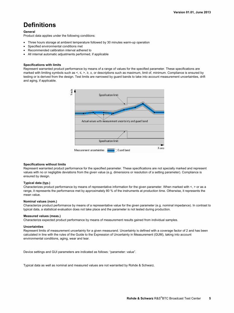
Specifications with limits Represent warranted product performance by means of a range of values for the specified parameter. These specifications are marked with limiting symbols such as <, ≤, >, ≥, ±, or descriptions such as maximum, limit of, minimum. Compliance is ensured by testing or is derived from the design. Test limits are narrowed by guard bands to take into account measurement uncertainties, drift and aging, if applicable.
Specifications without limits Represent warranted product performance for the specified parameter. These specifications are not specially marked and represent values with no or negligible deviations from the given value (e.g. dimensions or resolution of a setting parameter). Compliance is ensured by design.
Typical data (typ.) Characterizes product performance by means of representative information for the given parameter. When marked with <, > or as a range, it represents the performance met by approximately 80 % of the instruments at production time. Otherwise, it represents the mean value.
Nominal values (nom.) Characterize product performance by means of a representative value for the given parameter (e.g. nominal impedance). In contrast to typical data, a statistical evaluation does not take place and the parameter is not tested during production.
Measured values (meas.) Characterize expected product performance by means of measurement results gained from individual samples.
Uncertainties Represent limits of measurement uncertainty for a given measurand. Uncertainty is defined with a coverage factor of 2 and has been calculated in line with the rules of the Guide to the Expression of Uncertainty in Measurement (GUM), taking into account environmental conditions, aging, wear and tear.
Device settings and GUI parameters are indicated as follows: “parameter: value”.
Typical data as well as nominal and measured values are not warranted by Rohde & Schwarz.
Version 01.01, June 2013
6 Rohde & Schwarz R&S®BTC Broadcast Test Center
Frequency and baseband main module options
Frequency options One of the following frequency options must be installed in RF path A:
R&S®BTC-B3103 100 kHz to 3 GHz R&S®BTC-B3106 100 kHz to 6 GHz
If RF path A is equipped with R&S®BTC-B3103 or -B3106, one of the following frequency options can be installed in RF path B:
R&S®BTC-B3203 100 kHz to 3 GHz R&S®BTC-B3206 100 kHz to 6 GHz
Baseband main module options One of the following options must be installed:
R&S®BTC-B11 one I/Q path to RF section R&S®BTC-B12 two I/Q paths to RF section
If RF path B is equipped (or is planned to be retrofitted) with an R&S®BTC-B32xx frequency option, installation of the R&S®BTC-B12 baseband main module is strongly recommended. Otherwise, RF path B will be CW only.
Enhancement options In addition to frequency options, the following enhancement options can be installed (an R&S®BTC-B11 or R&S®BTC-B12 option must be installed as the baseband main module):
R&S®BTC-B3100 enhanced phase noise performance
The following combinations of frequency and enhancement options are possible:
Configuration of RF path A Possible configurations of RF path B R&S®BTC-B3103 or R&S®BTC-B3106 (path B not equipped)
R&S®BTC-B3203 or R&S®BTC-B3206 R&S®BTC-B3103 and R&S®BTC-B3100, or R&S®BTC-B3106 and R&S®BTC-B3100
(path B not equipped) R&S®BTC-B3203 or R&S®BTC-B3206 R&S®BTC-B3203 and R&S®BTC-B3100, or R&S®BTC-B3206 and R&S®BTC-B3100
The following option can be installed once, but is not fixed to a specific RF path.
R&S®BTC-K2500 digital baseband inputs/outputs
Version 01.01, June 2013
Rohde & Schwarz R&S®BTC Broadcast Test Center 7
RF characteristics
Frequency Range R&S®BTC-B3103, R&S®BTC-B3203 100 kHz to 3 GHz
R&S®BTC-B3106, R&S®BTC-B3206 100 kHz to 6 GHz Resolution of setting 0.001 Hz Resolution of synthesis fundamental frequency range = 750 MHz to 1500 MHz
standard 5 µHz (nom.) with R&S®BTC-B3100 option 0.2 µHz (nom.)
Setting time 1
to within < 1 × 10⁻⁷ for f > 200 MHz or < 124 Hz for f < 200 MHz, with GUI update stopped after IEC/IEEE bus delimiter < 4 ms, 3 ms (typ.)
Resolution of phase offset setting 0.1°
Frequency sweep Operating mode digital sweep in discrete steps Trigger modes free run auto
execute one full sweep single execute one step step sweep start and stop controlled by external trigger signal
start/stop
Trigger source external trigger signal (INST TRG A or B at rear), rotary knob, touchpanel, remote control
Sweep range full frequency range Sweep shape sawtooth, triangle Step size linear full frequency range
logarithmic 0.01 % to 100 % per step Dwell time setting range 1 ms to 10 s Dwell time setting resolution 0.1 ms
Reference frequency Frequency error at time of calibration in production
standard < 1 × 10⁻⁸ with R&S®BTC-B3100 option < 5 × 10⁻⁹
Aging after 30 days of uninterrupted operation standard 1 × 10⁻⁹/day, 1 × 10⁻⁷/year with R&S®BTC-B3100 option 5 × 10⁻¹⁰/day, 3 × 10⁻⁸/year
Temperature effect in temperature range from 0 °C to +50 °Cstandard 6 × 10⁻⁸ with R&S®BTC-B3100 option 6 × 10⁻⁹
Warm-up time to nominal thermostat temperature ≤ 10 min Output for internal reference frequency Connector type REF OUT on rear panel BNC female Output frequency sine wave 10 MHz or external input frequency Output level 2 dBm to 8 dBm,
5 dBm to 7 dBm (typ.) Source impedance 50 Ω (nom.) Input for external reference frequency Connector type REF IN on rear panel BNC female Input frequency 5 MHz, 10 MHz or 13 MHz Min. frequency locking range standard ±3 × 10⁻⁶
with R&S®BTC-B3100 option ±1.5 × 10⁻⁷ Input level range level limits ≥ –6 dBm, ≤ 19 dBm
recommended input level 0 dBm to 19 dBm Input impedance 50 Ω (nom.)
1 Installation of software that is not authorized by Rohde & Schwarz for use on the R&S®BTC or installation of antivirus software can deteriorate the
setting time performance.
Version 01.01, June 2013
8 Rohde & Schwarz R&S®BTC Broadcast Test Center
Input for electronic tuning of internal reference frequency Connector type EFC on rear panel BNC female Sensitivity standard 0.5 × 10⁻⁸/V to 3 × 10⁻⁸/V,
1 × 10⁻⁸/V to 2 × 10⁻⁸/V (typ.) with R&S®BTC-B3100 option 5 × 10⁻⁹/V to 2 × 10⁻⁸/V,
8 × 10⁻⁹/V to 9.5 × 10⁻⁹/V (typ.) Input voltage –10 V to +10 V Input impedance standard 10 kΩ (nom.)
with R&S®BTC-B3100 option 5 kΩ (nom.)
Level Setting range 100 kHz ≤ f < 1 MHz –145 dBm to +8 dBm
1 MHz ≤ f < 3 MHz –145 dBm to +13 dBm 3 MHz ≤ f ≤ 6 GHz –145 dBm to +30 dBm
Specified level range 100 kHz ≤ f < 1 MHz –120 dBm to +3 dBm (PEP) 2 1 MHz ≤ f < 3 MHz –120 dBm to +8 dBm (PEP) 2 3 MHz ≤ f ≤ 6 GHz –120 dBm to +18 dBm (PEP) 2
Resolution of setting 0.01 dB (nom.) Level error level setting characteristic: auto,
temperature range from +18 °C to +33 °C 100 kHz < f ≤ 3 GHz < 0.5 dB 3 GHz < f ≤ 6 GHz < 0.7 dB
Additional level error I/Q modulation < 0.15 dB Output impedance VSWR in 50 Ω system
level setting characteristic: auto < 1.6
Setting time 3
to < 0.1 dB deviation from final value, with GUI update stopped, no relay switchover, f > 10 MHz after IEC/IEEE bus delimiter < 4 ms, 3 ms (typ.)
Interruption-free level setting range level setting characteristic: uninterrupted level setting
> 20 dB
Reverse power (from 50 Ω source) maximum permissible RF power in output frequency range of RF path for f > 1 MHz 1 MHz < f ≤ 3 GHz 50 W 3 GHz < f ≤ 6 GHz 10 W
Maximum permissible DC voltage 50 V
Level sweep Operating mode digital sweep in discrete steps Trigger modes free run auto
execute one full sweep single execute one step step sweep start and stop controlled by external trigger signal
start/stop
Trigger source internal external trigger signal (INST TRG A or B at rear), rotary knob, touchpanel, remote control
Trigger slope external trigger signal positive, negative Sweep range interruption-free level sweep,
level setting characteristic: uninterrupted level setting
0.01 dB to 30 dB
Sweep shape sawtooth, triangle Step size setting resolution 0.01 dB Dwell time setting range 1 ms to 10 s Dwell time setting resolution 0.1 ms
2 PEP = peak envelope power. 3 Installation of software that is not authorized by Rohde & Schwarz for use on the R&S®BTC or installation of antivirus software can deteriorate the
setting time performance.

Version 01.01, June 2013
Rohde & Schwarz R&S®BTC Broadcast Test Center 9
Spectral purity Harmonics CW, level < 10 dBm < –30 dBc Nonharmonics CW, I/Q modulation (full-scale DC input), level > –10 dBm,
> 10 kHz offset from carrier and outside the modulation spectrum 100 kHz ≤ f ≤ 200 MHz < –77 dBc 200 MHz < f ≤ 1500 MHz < –80 dBc 1500 MHz < f ≤ 3 GHz < –74 dBc 3 GHz < f ≤ 6 GHz < –68 dBc
Nonharmonics with R&S®BTC-B3100 option
CW, I/Q modulation (full-scale DC input), level > –10 dBm, > 10 kHz offset from carrier and outside the modulation spectrum
100 kHz ≤ f ≤ 200 MHz < –77 dBc, –87 dBc (typ.) 200 MHz < f ≤ 1500 MHz < –90 dBc 1500 MHz < f ≤ 3 GHz < –84 dBc 3 GHz < f ≤ 6 GHz < –78 dBc
Power supply and mechanically related nonharmonics
at RF = 1 GHz, 50 Hz to 10 kHz from carrier
< –80 dBc
Subharmonics 1500 MHz < f ≤ 6000 MHz < –74 dBc Wideband noise carrier offset > 30 MHz, measurement bandwidth = 1 Hz
CW, level = 10 dBm 20 MHz ≤ f ≤ 200 MHz < –146 dBc, –149 dBc (typ.) 200 MHz < f ≤ 6 GHz < –150 dBc, –152 dBc (typ.)
I/Q modulation with full-scale internal single carrier signal, I/Q input gain = +2 dB, level = 10 dBm
20 MHz ≤ f ≤ 200 MHz < –139 dBc, –142 dBc (typ.) 200 MHz < f ≤ 1 GHz < –141 dBc, –144 dBc (typ.) 1 GHz < f ≤ 3 GHz < –142 dBc, –145 dBc (typ.) 3 GHz < f ≤ 6 GHz < –140 dBc, –143 dBc (typ.)
SSB phase noise CW, carrier offset = 20 kHz, measurement bandwidth = 1 Hz 20 MHz ≤ f ≤ 200 MHz < –128 dBc, –132 dBc (typ.) f = 1 GHz < –131 dBc, –135 dBc (typ.) f = 2 GHz < –125 dBc, –129 dBc (typ.) f = 3 GHz < –121 dBc, –125 dBc (typ.) f = 4 GHz < –119 dBc, –123 dBc (typ.) f = 6 GHz < –115 dBc, –119 dBc (typ.)
SSB phase noise with R&S®BTC-B3100 option
CW, carrier offset = 20 kHz, measurement bandwidth = 1 Hz 20 MHz ≤ f ≤ 200 MHz < –135 dBc, –138 dBc (typ.) f = 1 GHz < –136 dBc, –139 dBc (typ.) f = 2 GHz < –130 dBc, –133 dBc (typ.) f = 3 GHz < –126 dBc, –129 dBc (typ.) f = 4 GHz < –124 dBc, –127 dBc (typ.) f = 6 GHz < –120 dBc, –123 dBc (typ.)
Residual FM RMS value at f = 1 GHz 300 Hz to 3 kHz < 1 Hz 20 Hz to 23 kHz < 4 Hz
Residual AM RMS value (20 Hz to 23 kHz) < 0.02 %

Version 01.01, June 2013
10 Rohde & Schwarz R&S®BTC Broadcast Test Center
-180
-170
-160
-150
-140
-130
-120
-110
-100
-90
-80
-70
-60
-50
-40
-30
1 10 100 1k 10k 100k 1M 10M
SSB
phas
e no
ise
/ dB
c (1
Hz)
Offset frequency / Hz
100 MHz
1 GHz
3 GHz
6 GHz
Measured SSB phase noise performance with R&S®BTC-B3100 option.
-180
-170
-160
-150
-140
-130
-120
-110
-100
-90
-80
-70
-60
-50
-40
-30
1 10 100 1k 10k 100k 1M 10M
SSB
phas
e no
ise
/ dB
c (1
Hz)
Offset frequency / Hz
100 MHz
1 GHz
3 GHz
6 GHz
Measured SSB phase noise performance, standard instrument.
Version 01.01, June 2013
Rohde & Schwarz R&S®BTC Broadcast Test Center 11
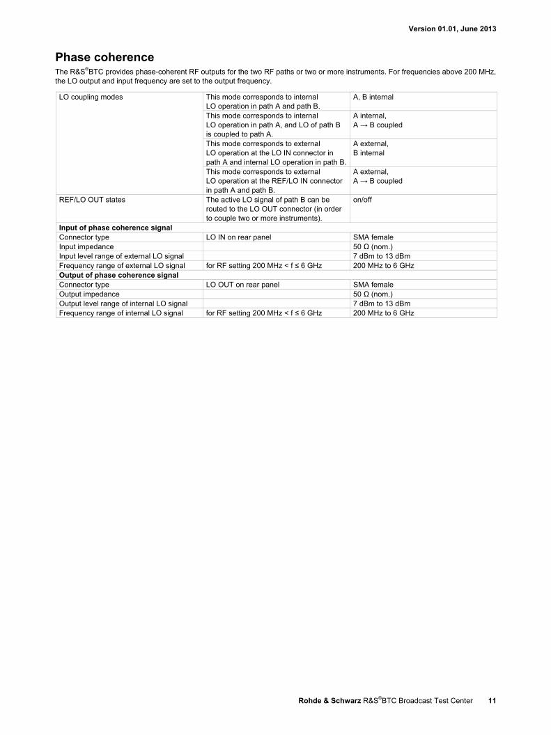
Phase coherence The R&S®BTC provides phase-coherent RF outputs for the two RF paths or two or more instruments. For frequencies above 200 MHz, the LO output and input frequency are set to the output frequency.
LO coupling modes This mode corresponds to internal LO operation in path A and path B.
A, B internal
This mode corresponds to internal LO operation in path A, and LO of path B is coupled to path A.
A internal, A → B coupled
This mode corresponds to external LO operation at the LO IN connector in path A and internal LO operation in path B.
A external, B internal
This mode corresponds to external LO operation at the REF/LO IN connector in path A and path B.
A external, A → B coupled
REF/LO OUT states The active LO signal of path B can be routed to the LO OUT connector (in order to couple two or more instruments).
on/off
Input of phase coherence signal Connector type LO IN on rear panel SMA female Input impedance 50 Ω (nom.) Input level range of external LO signal 7 dBm to 13 dBm Frequency range of external LO signal for RF setting 200 MHz < f ≤ 6 GHz 200 MHz to 6 GHz Output of phase coherence signal Connector type LO OUT on rear panel SMA female Output impedance 50 Ω (nom.) Output level range of internal LO signal 7 dBm to 13 dBm Frequency range of internal LO signal for RF setting 200 MHz < f ≤ 6 GHz 200 MHz to 6 GHz

Version 01.01, June 2013
12 Rohde & Schwarz R&S®BTC Broadcast Test Center
I/Q modulation
I/Q modulation performance Operating modes external wideband I/Q,
internal baseband I/Q RF modulation bandwidth with external wideband I/Q inputs, I/Q wideband on
1 MHz ≤ f ≤ 4 GHz ±25 % of carrier frequency f > 4 GHz ±1 GHz
with external wideband I/Q inputs, I/Q wideband off f ≤ 1000 MHz ±10 % of carrier frequency f > 1000 MHz ±100 MHz
with internal baseband I/Q, I/Q wideband on 1 MHz < f ≤ 320 MHz ±25 % of carrier frequency f > 320 MHz ±80 MHz
RF frequency response in specified RF modulation bandwidth
with external wideband I/Q inputs I/Q wideband on < 9 dB, < 6 dB (meas.) I/Q wideband off < 5 dB, < 3 dB (meas.)
with internal baseband I/Q, I/Q wideband on, optimization mode = high quality
< 1.0 dB, < 0.3 dB (meas.)
Carrier leakage 4 mode: internal baseband I/Q, referenced to full-scale input
< –55 dBc
Suppression of image sideband for entire instrument in modulation bandwidth
mode: internal baseband I/Q, up to 80 MHz I/Q BW
> 50 dB, 60 dB (typ.)
Two-tone IMD (2 carriers) PEP = 0 dBm up to 80 MHz carrier spacing < –40 dBc (typ.)
I/Q impairments (analog) These impairments are set within the analog I/Q modulator section. They can be used in external wideband I/Q mode and internal baseband I/Q mode. They cannot be applied to the analog or digital I/Q outputs. I offset, Q offset
setting range –10 % to +10 % resolution 0.01 %
gain imbalance setting range –1.0 dB to +1.0 dB resolution 0.01 dB
quadrature offset setting range –10° to +10° resolution 0.01°
4 Value applies after 1 hour warm-up time and recalibration for 4 hours of operation and temperature variations of less than +5 °C.

Version 01.01, June 2013
Rohde & Schwarz R&S®BTC Broadcast Test Center 13
Measured RF frequency response with internal baseband I/Q.
Analog I/Q inputs For each installed RF path A or B, one pair of I and Q inputs are available on the front panel. Analog I/Q input signals are directly applied to the analog I/Q modulation circuit and are not routed through the baseband section of the R&S®BTC.
Input mode single-ended Connector types I, Q on front panel (for each installed
RF path A or B) BNC female
Input impedance 50 Ω (nom.) VSWR up to 200 MHz < 1.2
200 MHz to 1 GHz < 1.35 Nominal input voltage for full-scale input
q2 2i + = 0.5 VV V
Damage voltage ±2 V
Version 01.01, June 2013
14 Rohde & Schwarz R&S®BTC Broadcast Test Center
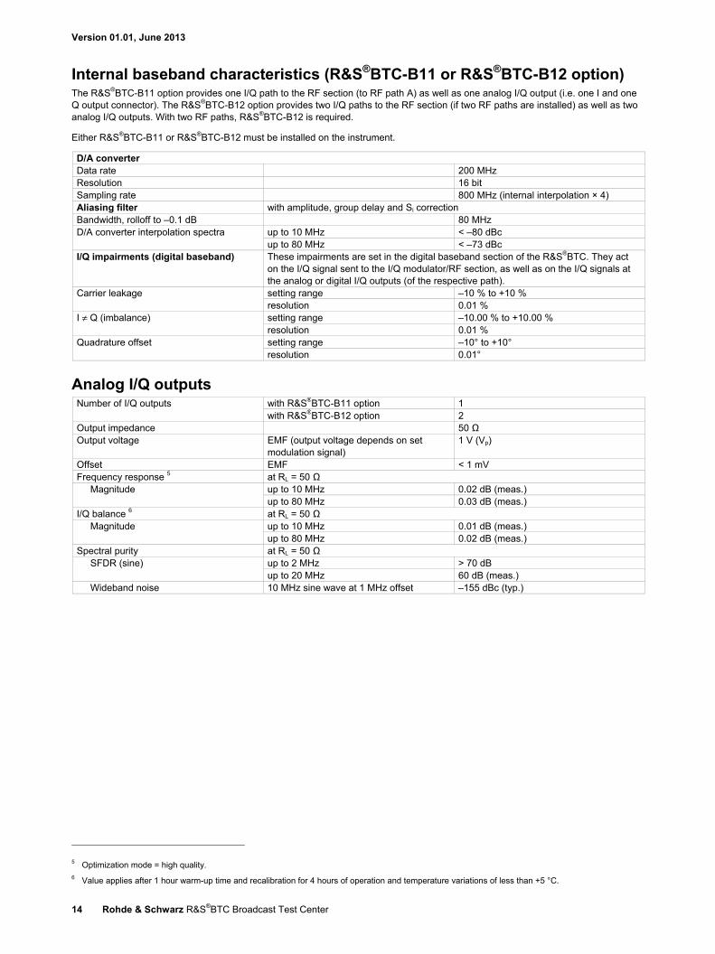
Internal baseband characteristics (R&S®BTC-B11 or R&S®BTC-B12 option) The R&S®BTC-B11 option provides one I/Q path to the RF section (to RF path A) as well as one analog I/Q output (i.e. one I and one Q output connector). The R&S®BTC-B12 option provides two I/Q paths to the RF section (if two RF paths are installed) as well as two analog I/Q outputs. With two RF paths, R&S®BTC-B12 is required.
Either R&S®BTC-B11 or R&S®BTC-B12 must be installed on the instrument.
D/A converter Data rate 200 MHz Resolution 16 bit Sampling rate 800 MHz (internal interpolation × 4) Aliasing filter with amplitude, group delay and Si correction Bandwidth, rolloff to –0.1 dB 80 MHz D/A converter interpolation spectra up to 10 MHz < –80 dBc
up to 80 MHz < –73 dBc I/Q impairments (digital baseband) These impairments are set in the digital baseband section of the R&S®BTC. They act
on the I/Q signal sent to the I/Q modulator/RF section, as well as on the I/Q signals at the analog or digital I/Q outputs (of the respective path).
Carrier leakage setting range –10 % to +10 % resolution 0.01 %
I ≠ Q (imbalance) setting range –10.00 % to +10.00 % resolution 0.01 %
Quadrature offset setting range –10° to +10° resolution 0.01°
Analog I/Q outputs Number of I/Q outputs with R&S®BTC-B11 option 1
with R&S®BTC-B12 option 2 Output impedance 50 Ω Output voltage EMF (output voltage depends on set
modulation signal) 1 V (Vp)
Offset EMF < 1 mV Frequency response 5 at RL = 50 Ω
Magnitude up to 10 MHz 0.02 dB (meas.) up to 80 MHz 0.03 dB (meas.)
I/Q balance 6 at RL = 50 Ω Magnitude up to 10 MHz 0.01 dB (meas.)
up to 80 MHz 0.02 dB (meas.) Spectral purity at RL = 50 Ω
SFDR (sine) up to 2 MHz > 70 dB up to 20 MHz 60 dB (meas.)
Wideband noise 10 MHz sine wave at 1 MHz offset –155 dBc (typ.)
5 Optimization mode = high quality. 6 Value applies after 1 hour warm-up time and recalibration for 4 hours of operation and temperature variations of less than +5 °C.
Version 01.01, June 2013
Rohde & Schwarz R&S®BTC Broadcast Test Center 15
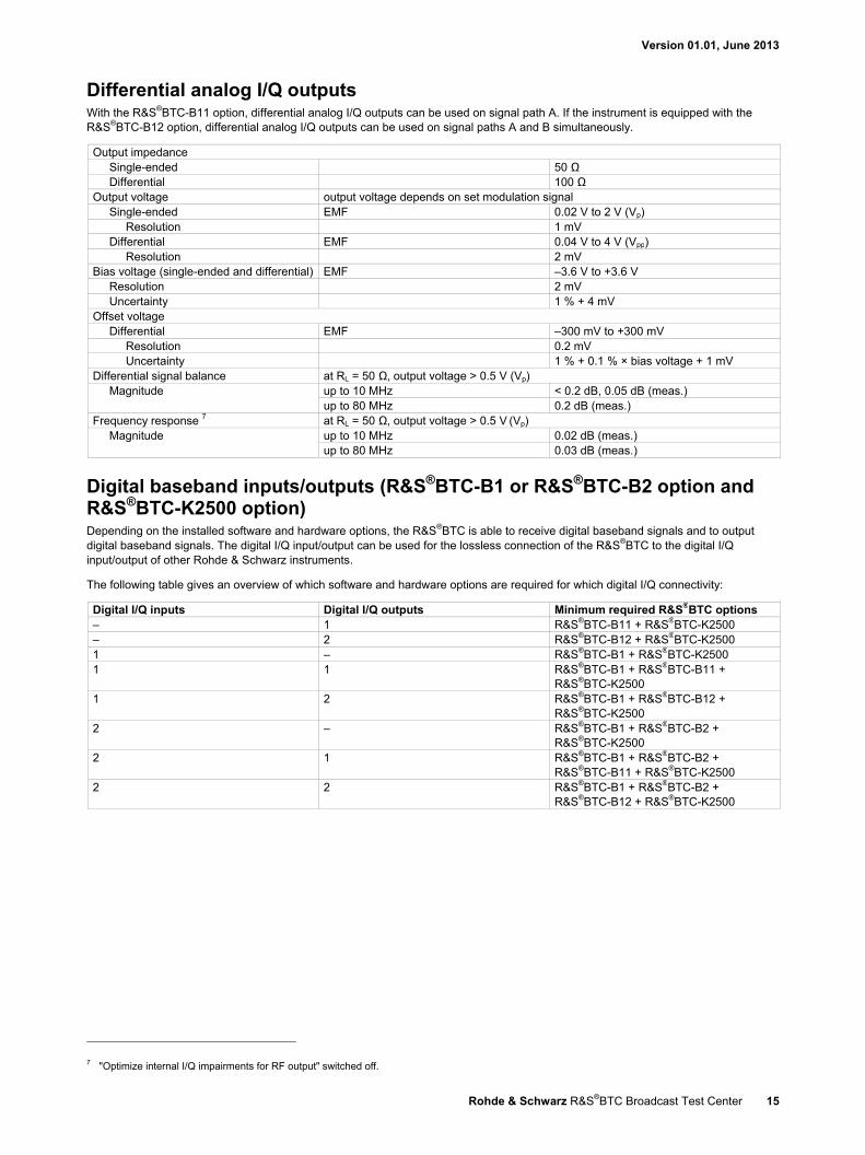
Differential analog I/Q outputs With the R&S®BTC-B11 option, differential analog I/Q outputs can be used on signal path A. If the instrument is equipped with the R&S®BTC-B12 option, differential analog I/Q outputs can be used on signal paths A and B simultaneously.
Output impedance Single-ended 50 Ω Differential 100 Ω
Output voltage output voltage depends on set modulation signal Single-ended EMF 0.02 V to 2 V (Vp)
Resolution 1 mV Differential EMF 0.04 V to 4 V (Vpp)
Resolution 2 mV Bias voltage (single-ended and differential) EMF –3.6 V to +3.6 V
Resolution 2 mV Uncertainty 1 % + 4 mV
Offset voltage Differential EMF –300 mV to +300 mV
Resolution 0.2 mV Uncertainty 1 % + 0.1 % × bias voltage + 1 mV
Differential signal balance at RL = 50 Ω, output voltage > 0.5 V (Vp) Magnitude up to 10 MHz < 0.2 dB, 0.05 dB (meas.)
up to 80 MHz 0.2 dB (meas.) Frequency response 7 at RL = 50 Ω, output voltage > 0.5 V (Vp)
Magnitude up to 10 MHz 0.02 dB (meas.) up to 80 MHz 0.03 dB (meas.)
Digital baseband inputs/outputs (R&S®BTC-B1 or R&S®BTC-B2 option and R&S®BTC-K2500 option) Depending on the installed software and hardware options, the R&S®BTC is able to receive digital baseband signals and to output digital baseband signals. The digital I/Q input/output can be used for the lossless connection of the R&S®BTC to the digital I/Q input/output of other Rohde & Schwarz instruments.
The following table gives an overview of which software and hardware options are required for which digital I/Q connectivity:
Digital I/Q inputs Digital I/Q outputs Minimum required R&S®BTC options – 1 R&S®BTC-B11 + R&S®BTC-K2500 – 2 R&S®BTC-B12 + R&S®BTC-K2500 1 – R&S®BTC-B1 + R&S®BTC-K2500 1 1 R&S®BTC-B1 + R&S®BTC-B11 +
R&S®BTC-K2500 1 2 R&S®BTC-B1 + R&S®BTC-B12 +
R&S®BTC-K2500 2 – R&S®BTC-B1 + R&S®BTC-B2 +
R&S®BTC-K2500 2 1 R&S®BTC-B1 + R&S®BTC-B2 +
R&S®BTC-B11 + R&S®BTC-K2500 2 2 R&S®BTC-B1 + R&S®BTC-B2 +
R&S®BTC-B12 + R&S®BTC-K2500
7 "Optimize internal I/Q impairments for RF output" switched off.
Version 01.01, June 2013
16 Rohde & Schwarz R&S®BTC Broadcast Test Center
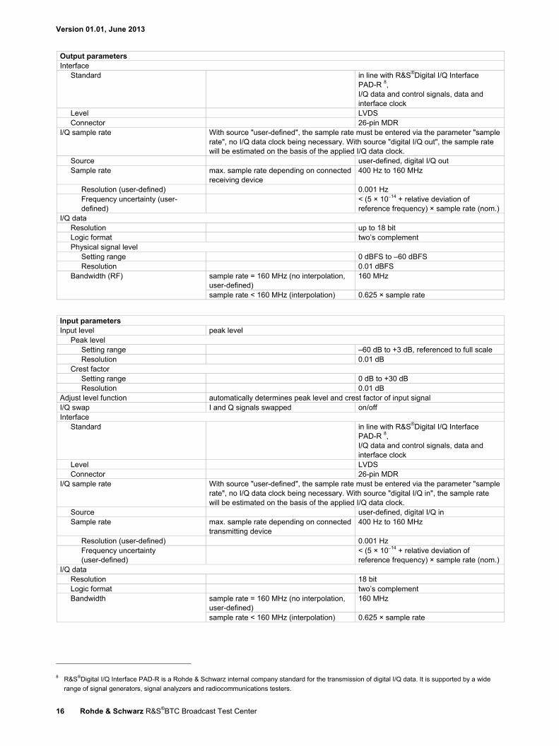
Output parameters Interface
Standard in line with R&S®Digital I/Q Interface PAD-R 8, I/Q data and control signals, data and interface clock
Level LVDS Connector 26-pin MDR
I/Q sample rate With source "user-defined", the sample rate must be entered via the parameter "sample rate", no I/Q data clock being necessary. With source "digital I/Q out", the sample rate will be estimated on the basis of the applied I/Q data clock.
Source user-defined, digital I/Q out Sample rate max. sample rate depending on connected
receiving device 400 Hz to 160 MHz
Resolution (user-defined) 0.001 Hz Frequency uncertainty (user-defined)
< (5 × 10⁻¹⁴ + relative deviation of reference frequency) × sample rate (nom.)
I/Q data Resolution up to 18 bit Logic format two’s complement Physical signal level
Setting range 0 dBFS to –60 dBFS Resolution 0.01 dBFS
Bandwidth (RF) sample rate = 160 MHz (no interpolation, user-defined)
160 MHz
sample rate < 160 MHz (interpolation) 0.625 × sample rate
Input parameters Input level peak level
Peak level Setting range –60 dB to +3 dB, referenced to full scale Resolution 0.01 dB
Crest factor Setting range 0 dB to +30 dB Resolution 0.01 dB
Adjust level function automatically determines peak level and crest factor of input signal I/Q swap I and Q signals swapped on/off Interface
Standard in line with R&S®Digital I/Q Interface PAD-R 8, I/Q data and control signals, data and interface clock
Level LVDS Connector 26-pin MDR
I/Q sample rate With source "user-defined", the sample rate must be entered via the parameter "sample rate", no I/Q data clock being necessary. With source "digital I/Q in", the sample rate will be estimated on the basis of the applied I/Q data clock.
Source user-defined, digital I/Q in Sample rate max. sample rate depending on connected
transmitting device 400 Hz to 160 MHz
Resolution (user-defined) 0.001 Hz Frequency uncertainty (user-defined)
< (5 × 10⁻¹⁴ + relative deviation of reference frequency) × sample rate (nom.)
I/Q data Resolution 18 bit Logic format two’s complement Bandwidth sample rate = 160 MHz (no interpolation,
user-defined) 160 MHz
sample rate < 160 MHz (interpolation) 0.625 × sample rate
8 R&S®Digital I/Q Interface PAD-R is a Rohde & Schwarz internal company standard for the transmission of digital I/Q data. It is supported by a wide
range of signal generators, signal analyzers and radiocommunications testers.
Version 01.01, June 2013
Rohde & Schwarz R&S®BTC Broadcast Test Center 17
Digital audio/video
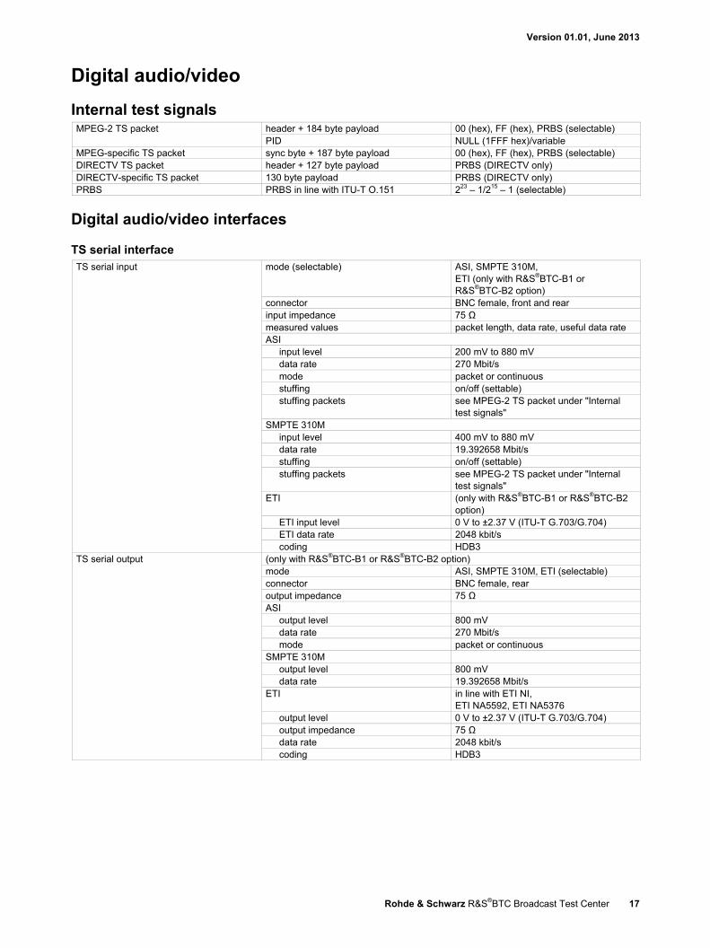
Internal test signals MPEG-2 TS packet header + 184 byte payload 00 (hex), FF (hex), PRBS (selectable)
PID NULL (1FFF hex)/variable MPEG-specific TS packet sync byte + 187 byte payload 00 (hex), FF (hex), PRBS (selectable) DIRECTV TS packet header + 127 byte payload PRBS (DIRECTV only) DIRECTV-specific TS packet 130 byte payload PRBS (DIRECTV only) PRBS PRBS in line with ITU-T O.151 223 – 1/215 – 1 (selectable)
Digital audio/video interfaces
TS serial interface TS serial input mode (selectable) ASI, SMPTE 310M,
ETI (only with R&S®BTC-B1 or R&S®BTC-B2 option)
connector BNC female, front and rear input impedance 75 Ω measured values packet length, data rate, useful data rate ASI
input level 200 mV to 880 mV data rate 270 Mbit/s mode packet or continuous stuffing on/off (settable) stuffing packets see MPEG-2 TS packet under "Internal
test signals" SMPTE 310M
input level 400 mV to 880 mV data rate 19.392658 Mbit/s stuffing on/off (settable) stuffing packets see MPEG-2 TS packet under "Internal
test signals" ETI (only with R&S®BTC-B1 or R&S®BTC-B2
option) ETI input level 0 V to ±2.37 V (ITU-T G.703/G.704) ETI data rate 2048 kbit/s coding HDB3
TS serial output (only with R&S®BTC-B1 or R&S®BTC-B2 option) mode ASI, SMPTE 310M, ETI (selectable) connector BNC female, rear output impedance 75 Ω ASI
output level 800 mV data rate 270 Mbit/s mode packet or continuous
SMPTE 310M output level 800 mV data rate 19.392658 Mbit/s
ETI in line with ETI NI, ETI NA5592, ETI NA5376
output level 0 V to ±2.37 V (ITU-T G.703/G.704) output impedance 75 Ω data rate 2048 kbit/s coding HDB3
Version 01.01, June 2013
18 Rohde & Schwarz R&S®BTC Broadcast Test Center
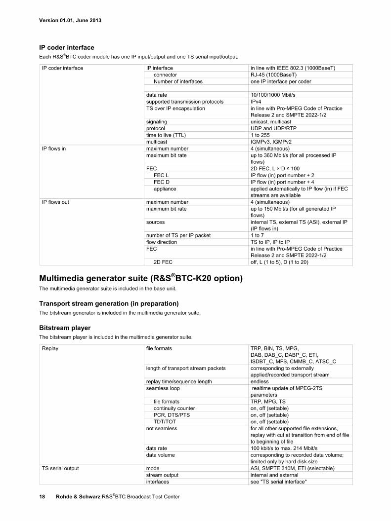
IP coder interface Each R&S®BTC coder module has one IP input/output and one TS serial input/output.
IP coder interface IP interface in line with IEEE 802.3 (1000BaseT) connector RJ-45 (1000BaseT) Number of interfaces one IP interface per coder
data rate 10/100/1000 Mbit/s supported transmission protocols IPv4 TS over IP encapsulation in line with Pro-MPEG Code of Practice
Release 2 and SMPTE 2022-1/2 signaling unicast, multicast protocol UDP and UDP/RTP time to live (TTL) 1 to 255 multicast IGMPv3, IGMPv2
IP flows in maximum number 4 (simultaneous) maximum bit rate up to 360 Mbit/s (for all processed IP
flows) FEC 2D FEC, L × D ≤ 100
FEC L IP flow (in) port number + 2 FEC D IP flow (in) port number + 4 appliance applied automatically to IP flow (in) if FEC
streams are available IP flows out maximum number 4 (simultaneous)
maximum bit rate up to 150 Mbit/s (for all generated IP flows)
sources internal TS, external TS (ASI), external IP (IP flows in)
number of TS per IP packet 1 to 7 flow direction TS to IP, IP to IP FEC in line with Pro-MPEG Code of Practice
Release 2 and SMPTE 2022-1/2 2D FEC off, L (1 to 5), D (1 to 20)
Multimedia generator suite (R&S®BTC-K20 option) The multimedia generator suite is included in the base unit.
Transport stream generation (in preparation) The bitstream generator is included in the multimedia generator suite.
Bitstream player The bitstream player is included in the multimedia generator suite.
Replay file formats TRP, BIN, TS, MPG, DAB, DAB_C, DABP_C, ETI, ISDBT_C, MFS, CMMB_C, ATSC_C
length of transport stream packets corresponding to externally applied/recorded transport stream
replay time/sequence length endless seamless loop realtime update of MPEG-2TS
parameters file formats TRP, MPG, TS continuity counter on, off (settable) PCR, DTS/PTS on, off (settable) TDT/TOT on, off (settable)
not seamless for all other supported file extensions, replay with cut at transition from end of file to beginning of file
data rate 100 kbit/s to max. 214 Mbit/s data volume corresponding to recorded data volume;
limited only by hard disk size TS serial output mode ASI, SMPTE 310M, ETI (selectable)
stream output internal and external interfaces see "TS serial interface"

Version 01.01, June 2013
Rohde & Schwarz R&S®BTC Broadcast Test Center 19
Test signals bitstream player in stop mode head 184 payload, head 187 payload, head 200 payload, sync 187 payload, sync 203 payload, sync 207 payload
bitstream player in play mode null packets payload "00" , payload "FF", payload "PRBS 15", payload "PRBS 23"
Signal set optional for additional digital signals and broadcasting standards, see ordering information for stream libraries
Stream libraries (R&S®LIB-Kxx options) A wide variety of libraries for different digital standards is available as a complement to the multimedia generator suite. For more information see ordering information.
Bitstream recorder (in preparation) The bitstream recorder is included in the multimedia generator suite.
Bitstream recorder in preparation mode ASI, SMPTE 310M, ETI (selectable) stream input internal and external interfaces see "TS serial interface"
Replay see "Bitstream player"
Broadcast multiplexer
DVB/ATSC multiplexer (in preparation) The broadcast multiplexer allows realtime multiplexing of MPEG-2 TS for DVB and ATSC. The broadcast multiplexer is included in the multimedia generator suite.
Broadcast multiplexer operating modes realtime multiplexing and remultiplexing mode DVB, ATSC supported standards DVB (DVB-T/DVB-T2, DVB-S/DVB-S2,
DVB-C/DVB-C2) ATSC (8VSB)
stream format MPEG-2 TS editor tool MPEG-2 TS tables
network information table (NIT) delivery descriptor filtering PID masking PID change of IDs NETWORK ID, TS ID, ON ID, SERVICE
ID, ELEMENTARY PID change of descriptors NIT descriptor loop, CAT descriptor loop,
PMT descriptor loop, SDT descriptor loop, ES descriptor loop
generation of descriptors NIT descriptor loop, CAT descriptor loop, PMT descriptor loop, SDT descriptor loop, ES descriptor loop
filter/disable TS parts network, TS, service, PID combine TS parts from different inputs network, TS, service dynamic stream handling change of IDs, change of descriptors,
filter/disable TS parts, combine TS parts generation of new services from ES library depending on available ES
Input supported streams user streams and Rohde & Schwarz streams
Output multiplexed streams without disruption output stream internal, external interfaces see "TS serial interface"
Version 01.01, June 2013
20 Rohde & Schwarz R&S®BTC Broadcast Test Center
Realtime gateway
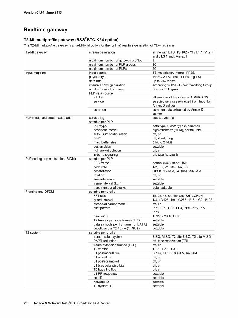
T2-MI multiprofile gateway (R&S®BTC-K24 option) The T2-MI multiprofile gateway is an additional option for the (online) realtime generation of T2-MI streams.
T2-MI gateway stream generation in line with ETSI TS 102 773 v1.1.1, v1.2.1 and v1.3.1, incl. Annex I
maximum number of gateway profiles 2 maximum number of PLP groups 20 maximum number of PLPs 20
Input mapping input source TS multiplexer, internal PRBS payload type MPEG-2 TS, content files (big TS) data rate up to 214 Mbit/s internal PRBS generation according to DVB-T2 V&V Working Group number of input streams one per PLP group PLP data source
full TS all services of the selected MPEG-2 TS service selected services extracted from input by
Annex D splitter common common data extracted by Annex D
splitter PLP mode and stream adaptation scheduling static, dynamic
settable per PLP PLP type data type 1, data type 2, common baseband mode high efficiency (HEM), normal (NM) auto ISSY configuration off, on ISSY off, short, long max. buffer size 0 bit to 2 Mbit design delay settable null packet deletion off, on in-band signaling off, type A, type B
PLP coding and modulation (BICM) settable per PLP FEC frame normal (64k), short (16k) code rate 1/2, 3/5, 2/3, 3/4, 4/5, 5/6 constellation QPSK, 16QAM, 64QAM, 256QAM rotation off, on time interleaver settable frame interval (Ijump) settable max. number of blocks auto, settable
Framing and OFDM settable per profile FFT size 1k, 2k, 4k, 8k, 16k and 32k COFDM guard interval 1/4, 19/128, 1/8, 19/256, 1/16, 1/32, 1/128 extended carrier mode off, on pilot pattern PP1, PP2, PP3, PP4, PP5, PP6, PP7,
PP8 bandwidth 1.7/5/6/7/8/10 MHz T2 frames per superframe (N_T2) settable data symbols per T2 frame (L_DATA) settable subslices per T2 frame (N_SUB) settable
T2 system settable per profile transmission system SISO, MISO, T2 Lite SISO, T2 Lite MISO PAPR reduction off, tone reservation (TR) future extension frames (FEF) off, on T2 version 1.1.1, 1.2.1, 1.3.1 L1 postmodulation BPSK, QPSK, 16QAM, 64QAM L1 repetition off, on L1 postscrambled off, on L1 bias balancing bits off, on T2 base lite flag off, on L1 RF frequency settable cell ID settable network ID settable T2 system ID settable

Version 01.01, June 2013
Rohde & Schwarz R&S®BTC Broadcast Test Center 21
Output stream structure DVB-T2 modulator interface (T2-MI) T2-MI MPEG-TS encapsulation single PID, full stream T2-MI PID variable T2-MI SID variable T2 timestamp null, relative data rate up to 72 Mbit/s per profile
Error injection
MPEG-2 transport stream error injection The error injection functionality is included in the multimedia generator suite.
Error injection operating mode realtime stream format MPEG-2 TS supported standards DVB (DVB-T/DVB-T2, DVB-S/DVB-S2,
DVB-C/DVB-C2) ATSC (8VSB) ISDB (ISDB-T)
error injection bit, byte, packet, table errors exchange, loss, modification table NIT
Input stream external IP, ASI internal user streams and
Rohde & Schwarz streams Output stream interfaces internal, external
external see MPEG-2 TS interface and IP interface multiplexed streams unencrypted
Analog audio/video
Audio player Audio player waveform file format WAV, WV (Rohde & Schwarz format) Waveform memory play time up to 670 s
resolution 16 bit for AF1 and 16 bit for AF2 nonvolatile memory hard disk, USB device
Audio signals number of signals 2 channels, AF1 and AF2 bandwidth DC to 15 kHz level 16-bit full scale in each channel,
corresponding to standard deviation frequency response < ±0.3 dB
Clock generation clock rate internal with resampling
Audio signal generator Audio signals number of signals 2, can be set separately
frequency 30 Hz to 15 kHz, in 1 Hz steps level –60 dBμ to +12 dBμ, in 0.01 dB steps,
6 dBμ corresponds to standard deviation
Version 01.01, June 2013
22 Rohde & Schwarz R&S®BTC Broadcast Test Center
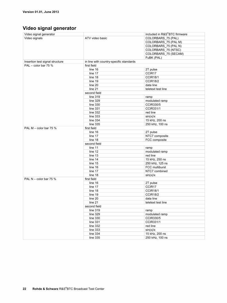
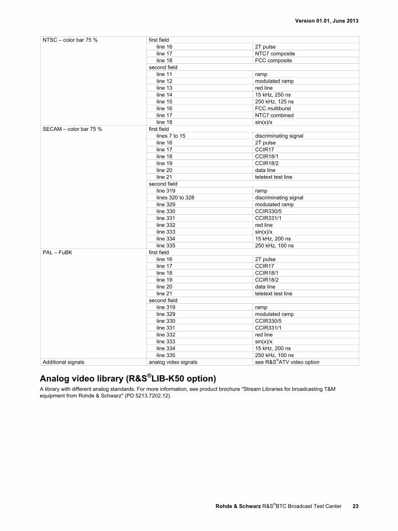
Video signal generator Video signal generator included in R&S®BTC firmware Video signals ATV video basic COLORBARS_75 (PAL)
COLORBARS_75 (PAL M) COLORBARS_75 (PAL N) COLORBARS_75 (NTSC) COLORBARS_75 (SECAM) FuBK (PAL)
Insertion test signal structure in line with country-specific standards PAL – color bar 75 % first field
line 16 2T pulse line 17 CCIR17 line 18 CCIR18/1 line 19 CCIR18/2 line 20 data line line 21 teletext test line
second field line 319 ramp line 329 modulated ramp line 330 CCIR330/5 line 331 CCIR331/1 line 332 red line line 333 sin(x)/x line 334 15 kHz, 200 ns line 335 250 kHz, 100 ns
PAL M – color bar 75 % first field line 16 2T pulse line 17 NTC7 composite line 18 FCC composite
second field line 11 ramp line 12 modulated ramp line 13 red line line 14 15 kHz, 250 ns line 15 250 kHz, 125 ns line 16 FCC multiburst line 17 NTC7 combined line 18 sin(x)/x
PAL N – color bar 75 % first field line 16 2T pulse line 17 CCIR17 line 18 CCIR18/1 line 19 CCIR18/2 line 20 data line line 21 teletext test line
second field line 319 ramp line 329 modulated ramp line 330 CCIR330/5 line 331 CCIR331/1 line 332 red line line 333 sin(x)/x line 334 15 kHz, 200 ns line 335 250 kHz, 100 ns
Version 01.01, June 2013
Rohde & Schwarz R&S®BTC Broadcast Test Center 23
NTSC – color bar 75 % first field line 16 2T pulse line 17 NTC7 composite line 18 FCC composite
second field line 11 ramp line 12 modulated ramp line 13 red line line 14 15 kHz, 250 ns line 15 250 kHz, 125 ns line 16 FCC multiburst line 17 NTC7 combined line 18 sin(x)/x
SECAM – color bar 75 % first field lines 7 to 15 discriminating signal line 16 2T pulse line 17 CCIR17 line 18 CCIR18/1 line 19 CCIR18/2 line 20 data line line 21 teletext test line
second field line 319 ramp lines 320 to 328 discriminating signal line 329 modulated ramp line 330 CCIR330/5 line 331 CCIR331/1 line 332 red line line 333 sin(x)/x line 334 15 kHz, 200 ns line 335 250 kHz, 100 ns
PAL – FuBK first field line 16 2T pulse line 17 CCIR17 line 18 CCIR18/1 line 19 CCIR18/2 line 20 data line line 21 teletext test line
second field line 319 ramp line 329 modulated ramp line 330 CCIR330/5 line 331 CCIR331/1 line 332 red line line 333 sin(x)/x line 334 15 kHz, 200 ns line 335 250 kHz, 100 ns
Additional signals analog video signals see R&S®ATV video option
Analog video library (R&S®LIB-K50 option) A library with different analog standards. For more information, see product brochure "Stream Libraries for broadcasting T&M equipment from Rohde & Schwarz" (PD 5213.7202.12).
Version 01.01, June 2013
24 Rohde & Schwarz R&S®BTC Broadcast Test Center
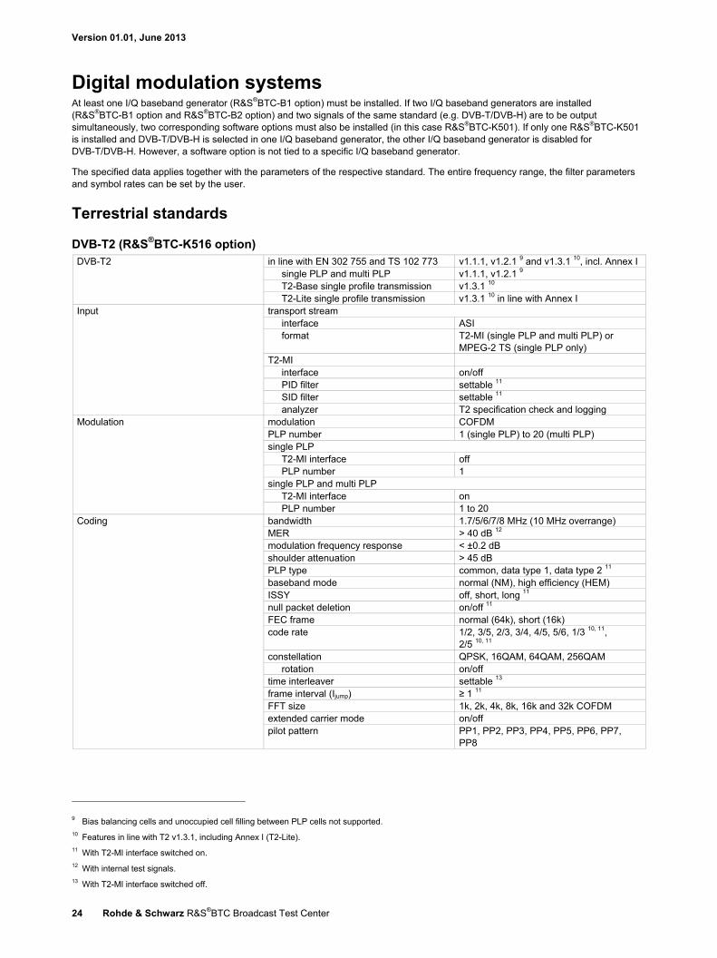
Digital modulation systems At least one I/Q baseband generator (R&S®BTC-B1 option) must be installed. If two I/Q baseband generators are installed (R&S®BTC-B1 option and R&S®BTC-B2 option) and two signals of the same standard (e.g. DVB-T/DVB-H) are to be output simultaneously, two corresponding software options must also be installed (in this case R&S®BTC-K501). If only one R&S®BTC-K501 is installed and DVB-T/DVB-H is selected in one I/Q baseband generator, the other I/Q baseband generator is disabled for DVB-T/DVB-H. However, a software option is not tied to a specific I/Q baseband generator.
The specified data applies together with the parameters of the respective standard. The entire frequency range, the filter parameters and symbol rates can be set by the user.
Terrestrial standards
DVB-T2 (R&S®BTC-K516 option) DVB-T2 in line with EN 302 755 and TS 102 773 v1.1.1, v1.2.1 9 and v1.3.1 10, incl. Annex I
single PLP and multi PLP v1.1.1, v1.2.1 9 T2-Base single profile transmission v1.3.1 10 T2-Lite single profile transmission v1.3.1 10 in line with Annex I
Input transport stream interface ASI format T2-MI (single PLP and multi PLP) or
MPEG-2 TS (single PLP only) T2-MI
interface on/off PID filter settable 11 SID filter settable 11 analyzer T2 specification check and logging
Modulation modulation COFDM PLP number 1 (single PLP) to 20 (multi PLP) single PLP
T2-MI interface off PLP number 1
single PLP and multi PLP T2-MI interface on PLP number 1 to 20
Coding bandwidth 1.7/5/6/7/8 MHz (10 MHz overrange) MER > 40 dB 12 modulation frequency response < ±0.2 dB shoulder attenuation > 45 dB PLP type common, data type 1, data type 2 11 baseband mode normal (NM), high efficiency (HEM) ISSY off, short, long 11 null packet deletion on/off 11 FEC frame normal (64k), short (16k) code rate 1/2, 3/5, 2/3, 3/4, 4/5, 5/6, 1/3 10, 11,
2/5 10, 11 constellation QPSK, 16QAM, 64QAM, 256QAM
rotation on/off time interleaver settable 13 frame interval (Ijump) ≥ 1 11 FFT size 1k, 2k, 4k, 8k, 16k and 32k COFDM extended carrier mode on/off pilot pattern PP1, PP2, PP3, PP4, PP5, PP6, PP7,
PP8
9 Bias balancing cells and unoccupied cell filling between PLP cells not supported. 10 Features in line with T2 v1.3.1, including Annex I (T2-Lite). 11 With T2-MI interface switched on. 12 With internal test signals. 13 With T2-MI interface switched off.
Version 01.01, June 2013
Rohde & Schwarz R&S®BTC Broadcast Test Center 25
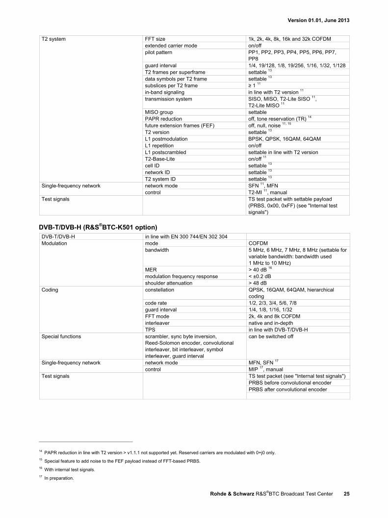
T2 system FFT size 1k, 2k, 4k, 8k, 16k and 32k COFDM extended carrier mode on/off pilot pattern PP1, PP2, PP3, PP4, PP5, PP6, PP7,
PP8 guard interval 1/4, 19/128, 1/8, 19/256, 1/16, 1/32, 1/128 T2 frames per superframe settable 13 data symbols per T2 frame settable 13 subslices per T2 frame ≥ 1 11 in-band signaling in line with T2 version 11 transmission system SISO, MISO, T2-Lite SISO 11,
T2-Lite MISO 11 MISO group settable PAPR reduction off, tone reservation (TR) 14 future extension frames (FEF) off, null, noise 11, 15 T2 version settable 13 L1 postmodulation BPSK, QPSK, 16QAM, 64QAM L1 repetition on/off L1 postscrambled settable in line with T2 version T2-Base-Lite on/off 11 cell ID settable 13 network ID settable 13 T2 system ID settable 13
Single-frequency network network mode SFN 11, MFN control T2-MI 11, manual
Test signals TS test packet with settable payload (PRBS, 0x00, 0xFF) (see "Internal test signals")
DVB-T/DVB-H (R&S®BTC-K501 option) DVB-T/DVB-H in line with EN 300 744/EN 302 304 Modulation mode COFDM
bandwidth 5 MHz, 6 MHz, 7 MHz, 8 MHz (settable for variable bandwidth: bandwidth used 1 MHz to 10 MHz)
MER > 40 dB 16 modulation frequency response < ±0.2 dB shoulder attenuation > 48 dB
Coding constellation QPSK, 16QAM, 64QAM, hierarchical coding
code rate 1/2, 2/3, 3/4, 5/6, 7/8 guard interval 1/4, 1/8, 1/16, 1/32 FFT mode 2k, 4k and 8k COFDM interleaver native and in-depth TPS in line with DVB-T/DVB-H
Special functions scrambler, sync byte inversion, Reed-Solomon encoder, convolutional interleaver, bit interleaver, symbol interleaver, guard interval
can be switched off
Single-frequency network network mode MFN, SFN 17 control MIP 17, manual
Test signals TS test packet (see "Internal test signals") PRBS before convolutional encoder PRBS after convolutional encoder
14 PAPR reduction in line with T2 version > v1.1.1 not supported yet. Reserved carriers are modulated with 0+j0 only. 15 Special feature to add noise to the FEF payload instead of FFT-based PRBS. 16 With internal test signals. 17 In preparation.
Version 01.01, June 2013
26 Rohde & Schwarz R&S®BTC Broadcast Test Center
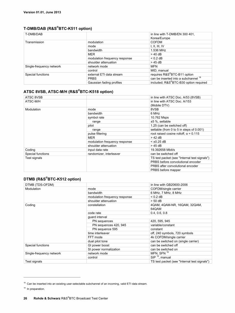
T-DMB/DAB (R&S®BTC-K511 option) T-DMB/DAB in line with T-DMB/EN 300 401,
Korea/Europe Transmission modulation COFDM
mode I, II, III, IV bandwidth 1.536 MHz MER > 40 dB modulation frequency response < 0.2 dB shoulder attenuation > 45 dB
Single-frequency network network mode MFN control MID, manual
Special functions external ETI data stream requires R&S®BTC-B11 option PRBS can be inserted into a subchannel 18 Gaussian fading profiles included; R&S®BTC-B30 option required
ATSC 8VSB, ATSC-M/H (R&S®BTC-K518 option) ATSC 8VSB in line with ATSC Doc. A/53 (8VSB) ATSC-M/H in line with ATSC Doc. A/153
(Mobile DTV) Modulation mode 8VSB
bandwidth 6 MHz symbol rate 10.762 Msps
range ±5 %, settable pilot 1.25 (can be switched off)
range settable (from 0 to 5 in steps of 0.001) pulse filtering root raised cosine rolloff, α = 0.115 MER > 42 dB modulation frequency response < ±0.25 dB shoulder attenuation > 45 dB
Coding input data rate 19.392658 Mbit/s Special functions randomizer, interleaver can be switched off Test signals TS test packet (see "Internal test signals")
PRBS before convolutional encoder PRBS after convolutional encoder PRBS before mapper
DTMB (R&S®BTC-K512 option) DTMB (TDS-OFDM) in line with GB20600-2006 Modulation mode COFDM/single carrier
bandwidth 6 MHz, 7 MHz, 8 MHz modulation frequency response < 0.2 dB shoulder attenuation > 50 dB
Coding
constellation 4QAM, 4QAM-NR, 16QAM, 32QAM, 64QAM
code rate 0.4, 0.6, 0.8 guard interval
PN sequences 420, 595, 945 PN sequences 420, 945 variable/constant PN sequence 595 constant
time interleaver off, 240 symbols, 720 symbols FFT mode 4k COFDM/single carrier dual pilot tone can be switched on (single carrier)
Special functions GI power boost can be switched off SI power normalization can be switched on
Single-frequency network network mode MFN, SFN 19 control SIP 19, manual
Test signals TS test packet (see "Internal test signals")
18 Can be inserted into an existing user-selectable subchannel of an incoming, valid ETI data stream. 19 In preparation.
Version 01.01, June 2013
Rohde & Schwarz R&S®BTC Broadcast Test Center 27
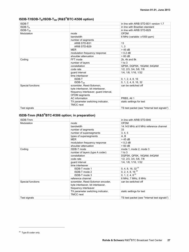
ISDB-T/ISDB-TB/ISDB-TSB (R&S®BTC-K506 option) ISDB-T in line with ARIB STD-B31 version 1.7 ISDB-TB in line with Brazilian standard ISDB-TSB in line with ARIB STD-B29 Modulation mode OFDM
bandwidth 6 MHz (variable: ±1000 ppm) number of segments
ARIB STD-B31 13 ARIB STD-B29 1, 3
MER > 45 dB modulation frequency response < 0.2 dB shoulder attenuation > 60 dB
Coding FFT mode 2k, 4k and 8k number of layers 1 to 3 constellation QPSK, DQPSK, 16QAM, 64QAM code rate 1/2, 2/3, 3/4, 5/6, 7/8 guard interval 1/4, 1/8, 1/16, 1/32 time interleaver
ISDB-T 0, 1, 2, 4, 8, 16 ISDB-TSB 0, 1, 2, 4, 8, 16, 32
Special functions scrambler, Reed-Solomon, byte interleaver, bit interleaver, frequency interleaver, guard interval, OFDM segments
can be switched off
AC information PRBS, All 1 TX parameter switching indicator, TMCC next
static settings for test
Test signals TS test packet (see "Internal test signals")
ISDB-Tmm (R&S®BTC-K506 option; in preparation) ISDB-Tmm in line with ARIB STD-B46 Modulation mode OFDM
bandwidth 14.143 MHz at 6 MHz reference channel number of segments 33 number of supersegments 3, 4, 5 types of supersegments A, B MER > 45 dB modulation frequency response < 0.2 dB shoulder attenuation > 60 dB
Coding ISDB-T mode mode 1, mode 2, mode 3 number of layers (type A coder) 1 to 3 constellation DQPSK, QPSK, 16QAM, 64QAM code rate 1/2, 2/3, 3/4, 5/6, 7/8 guard interval 1/4, 1/8, 1/16, 1/32 time interleaver
ISDB-T mode 1 0, 4, 8, 16, 32 20 ISDB-T mode 2 0, 2, 4, 8, 16 20 ISDB-T mode 3 0, 1, 2, 4, 8 20
reference channel 6 MHz, 7 MHz, 8 MHz Special functions scrambler, Reed-Solomon encoder,
byte interleaver, bit interleaver, frequency interleaver
can be switched off
TX parameter switching indicator, TMCC next
static settings for test
Test signals TS test packet (see "Internal test signals")
20 Type B coder only.
Version 01.01, June 2013
28 Rohde & Schwarz R&S®BTC Broadcast Test Center
Cable standards
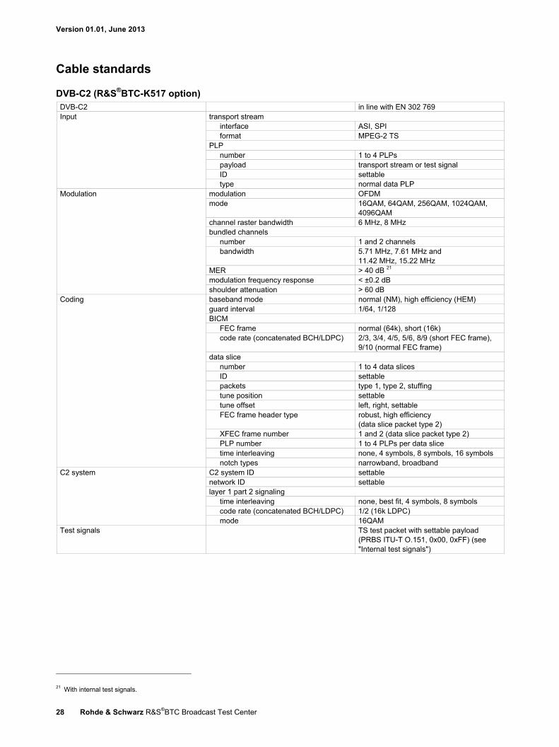
DVB-C2 (R&S®BTC-K517 option) DVB-C2 in line with EN 302 769 Input transport stream
interface ASI, SPI format MPEG-2 TS
PLP number 1 to 4 PLPs payload transport stream or test signal ID settable type normal data PLP
Modulation modulation OFDM mode 16QAM, 64QAM, 256QAM, 1024QAM,
4096QAM channel raster bandwidth 6 MHz, 8 MHz bundled channels
number 1 and 2 channels bandwidth 5.71 MHz, 7.61 MHz and
11.42 MHz, 15.22 MHz MER > 40 dB 21 modulation frequency response < ±0.2 dB shoulder attenuation > 60 dB
Coding baseband mode normal (NM), high efficiency (HEM) guard interval 1/64, 1/128 BICM
FEC frame normal (64k), short (16k) code rate (concatenated BCH/LDPC) 2/3, 3/4, 4/5, 5/6, 8/9 (short FEC frame),
9/10 (normal FEC frame) data slice
number 1 to 4 data slices ID settable packets type 1, type 2, stuffing tune position settable tune offset left, right, settable FEC frame header type robust, high efficiency
(data slice packet type 2) XFEC frame number 1 and 2 (data slice packet type 2) PLP number 1 to 4 PLPs per data slice time interleaving none, 4 symbols, 8 symbols, 16 symbols notch types narrowband, broadband
C2 system C2 system ID settable network ID settable layer 1 part 2 signaling
time interleaving none, best fit, 4 symbols, 8 symbols code rate (concatenated BCH/LDPC) 1/2 (16k LDPC) mode 16QAM
Test signals TS test packet with settable payload (PRBS ITU-T O.151, 0x00, 0xFF) (see "Internal test signals")
21 With internal test signals.
Version 01.01, June 2013
Rohde & Schwarz R&S®BTC Broadcast Test Center 29
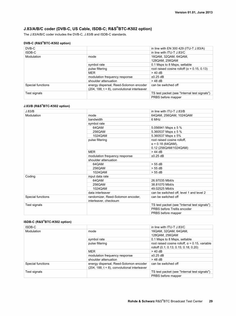
J.83/A/B/C coder (DVB-C, US Cable, ISDB-C; R&S®BTC-K502 option) The J.83/A/B/C coder includes the DVB-C, J.83/B and ISDB-C standards.
DVB-C (R&S®BTC-K502 option)
DVB-C in line with EN 300 429 (ITU-T J.83/A) ISDB-C in line with ITU-T J.83/C Modulation mode 16QAM, 32QAM, 64QAM,
128QAM, 256QAM symbol rate 0.1 Msps to 8 Msps, settable pulse filtering root raised cosine rolloff (α = 0.15, 0.13) MER > 40 dB modulation frequency response ±0.25 dB shoulder attenuation > 48 dB
Special functions energy dispersal, Reed-Solomon encoder (204, 188, t = 8), convolutional interleaver
can be switched off
Test signals TS test packet (see "Internal test signals") PRBS before mapper
J.83/B (R&S®BTC-K502 option)
J.83/B in line with ITU-T J.83/B Modulation mode 64QAM, 256QAM, 1024QAM
bandwidth 6 MHz symbol rate
64QAM 5.056941 Msps ± 5 % 256QAM 5.360537 Msps ± 5 % 1024QAM 5.360537 Msps ± 5%
pulse filtering root raised cosine rolloff, α = 0.18 (64QAM), 0.12 (256QAM/1024QAM)
MER > 44 dB modulation frequency response ±0.25 dB shoulder attenuation
64QAM > 55 dB 256QAM > 55 dB 1024QAM > 55 dB
Coding input data rate 64QAM 26.97035 Mbit/s 256QAM 38.81070 Mbit/s 1024QAM 49.02525 Mbit/s
data interleaver can be switched off, level 1 and level 2 Special functions randomizer, Reed-Solomon encoder,
interleaver, checksum can be switched off
Test signals TS test packet (see "Internal test signals") PRBS before Trellis encoder PRBS before mapper
ISDB-C (R&S®BTC-K502 option)
ISDB-C in line with ITU-T J.83/C Modulation mode 16QAM, 32QAM, 64QAM,
128QAM, 256QAM symbol rate 0.1 Msps to 8 Msps, settable pulse filtering root raised cosine rolloff, α = 0.15, variable
rolloff (0.1; 0.13; 0.15; 0.18; 0.20) MER > 40 dB modulation frequency response ±0.25 dB shoulder attenuation > 48 dB
Special functions energy dispersal, Reed-Solomon encoder (204, 188, t = 8), convolutional interleaver
can be switched off
Test signals TS test packet (see "Internal test signals") PRBS before mapper
Version 01.01, June 2013
30 Rohde & Schwarz R&S®BTC Broadcast Test Center
Satellite standards
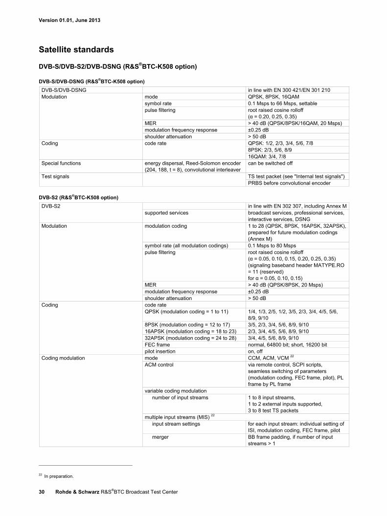
DVB-S/DVB-S2/DVB-DSNG (R&S®BTC-K508 option)
DVB-S/DVB-DSNG (R&S®BTC-K508 option)
DVB-S/DVB-DSNG in line with EN 300 421/EN 301 210 Modulation mode QPSK, 8PSK, 16QAM
symbol rate 0.1 Msps to 66 Msps, settable pulse filtering root raised cosine rolloff
(α = 0.20, 0.25, 0.35) MER > 40 dB (QPSK/8PSK/16QAM, 20 Msps) modulation frequency response ±0.25 dB shoulder attenuation > 50 dB
Coding code rate QPSK: 1/2, 2/3, 3/4, 5/6, 7/8 8PSK: 2/3, 5/6, 8/9 16QAM: 3/4, 7/8
Special functions energy dispersal, Reed-Solomon encoder (204, 188, t = 8), convolutional interleaver
can be switched off
Test signals TS test packet (see "Internal test signals") PRBS before convolutional encoder
DVB-S2 (R&S®BTC-K508 option)
DVB-S2 in line with EN 302 307, including Annex Msupported services broadcast services, professional services,
interactive services, DSNG Modulation modulation coding 1 to 28 (QPSK, 8PSK, 16APSK, 32APSK),
prepared for future modulation codings (Annex M)
symbol rate (all modulation codings) 0.1 Msps to 80 Msps pulse filtering root raised cosine rolloff
(α = 0.05, 0.10, 0.15, 0.20, 0.25, 0.35) (signaling baseband header MATYPE.RO = 11 (reserved) for α = 0.05, 0.10, 0.15)
MER > 40 dB (QPSK/8PSK, 20 Msps) modulation frequency response ±0.25 dB shoulder attenuation > 50 dB
Coding code rate QPSK (modulation coding = 1 to 11) 1/4, 1/3, 2/5, 1/2, 3/5, 2/3, 3/4, 4/5, 5/6,
8/9, 9/10 8PSK (modulation coding = 12 to 17) 3/5, 2/3, 3/4, 5/6, 8/9, 9/10 16APSK (modulation coding = 18 to 23) 2/3, 3/4, 4/5, 5/6, 8/9, 9/10 32APSK (modulation coding = 24 to 28) 3/4, 4/5, 5/6, 8/9, 9/10 FEC frame normal, 64800 bit; short, 16200 bit pilot insertion on, off
Coding modulation mode CCM, ACM, VCM 22 ACM control via remote control, SCPI scripts,
seamless switching of parameters (modulation coding, FEC frame, pilot), PL frame by PL frame
variable coding modulation number of input streams 1 to 8 input streams,
1 to 2 external inputs supported, 3 to 8 test TS packets
multiple input streams (MIS) 22 input stream settings for each input stream: individual setting of
ISI, modulation coding, FEC frame, pilot merger BB frame padding, if number of input
streams > 1
22 In preparation.

Version 01.01, June 2013
Rohde & Schwarz R&S®BTC Broadcast Test Center 31
Annex M 23 mode off, on number of time slices 1 to 8 time slices,
time slice 1: real DVB-S2 FEC, time slices 2 to 8: PRBS data symbols
time slice settings for each time slice: individual setting of TSN, modulation coding, FEC frame, pilot
Special function PL scrambling sequence ID 0x00000 to 0x3FFFD Test signals TS test packet (see "Internal test signals")
DIRECTV legacy modulation (R&S®BTC-K509 option) DIRECTV legacy modulation in line with DIRECTV transmission
specifications Modulation mode QPSK
symbol rate 20 Msps overrange 1 Msps to 30 Msps
pulse-shaping filter root raised cosine rolloff, α = 0.20, variable rolloff (0.15, 0.20, 0.25, 0.35)
MER 38 dB (20 Msps) modulation frequency response < ±0.25 dB shoulder attenuation 50 dB
Coding code rate 1/2, 2/3, 6/7 Special function user-specific DIRECTV streams can be replayed in 188 byte format,
requires R&S®BTC-K21, R&S®BTC-K22 option
error insertion after convolutional encoder Test signals TS test packet (see "Internal test signals")
23 In preparation.
Version 01.01, June 2013
32 Rohde & Schwarz R&S®BTC Broadcast Test Center
Analog modulation systems
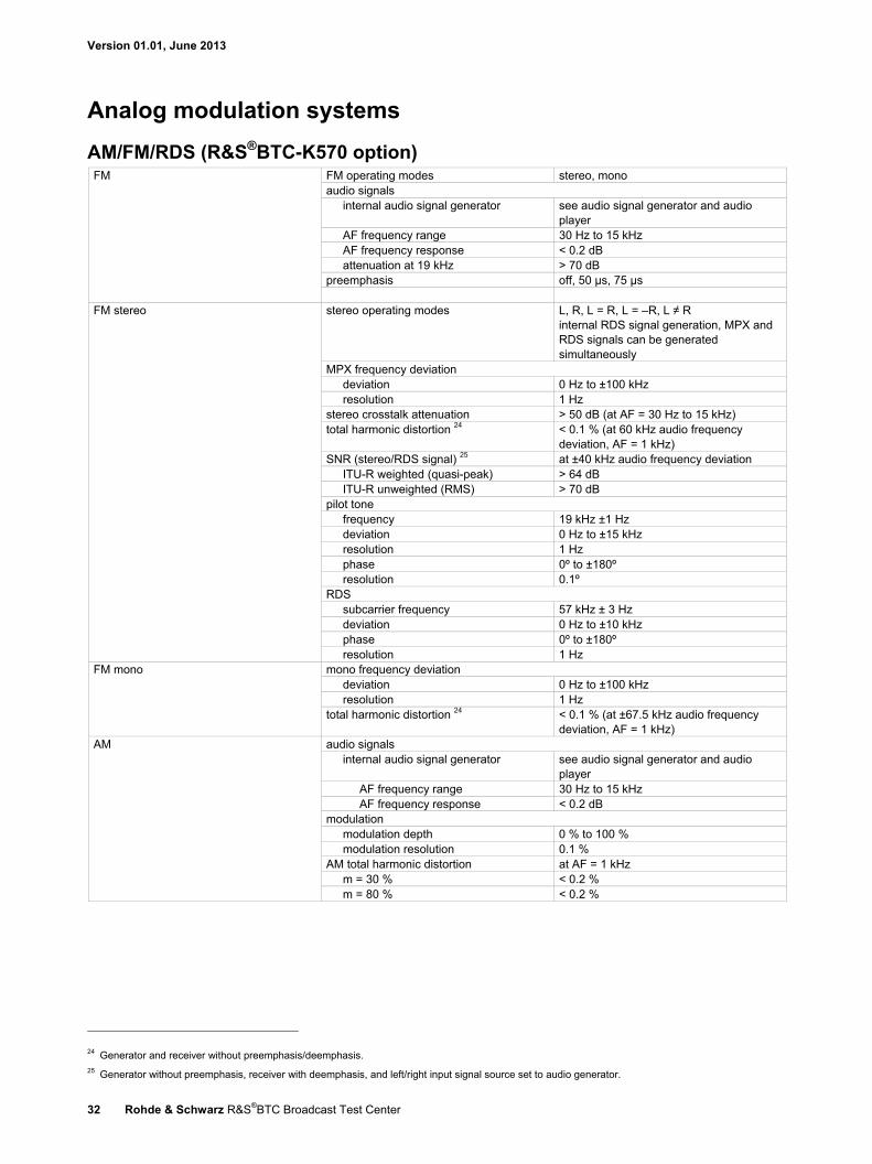
AM/FM/RDS (R&S®BTC-K570 option) FM FM operating modes stereo, mono
audio signals internal audio signal generator see audio signal generator and audio
player AF frequency range 30 Hz to 15 kHz AF frequency response < 0.2 dB attenuation at 19 kHz > 70 dB
preemphasis off, 50 µs, 75 µs
FM stereo stereo operating modes L, R, L = R, L = –R, L ≠ R internal RDS signal generation, MPX and RDS signals can be generated simultaneously
MPX frequency deviation deviation 0 Hz to ±100 kHz resolution 1 Hz
stereo crosstalk attenuation > 50 dB (at AF = 30 Hz to 15 kHz) total harmonic distortion 24 < 0.1 % (at 60 kHz audio frequency
deviation, AF = 1 kHz) SNR (stereo/RDS signal) 25 at ±40 kHz audio frequency deviation
ITU-R weighted (quasi-peak) > 64 dB ITU-R unweighted (RMS) > 70 dB
pilot tone frequency 19 kHz ±1 Hz deviation 0 Hz to ±15 kHz resolution 1 Hz phase 0º to ±180º resolution 0.1º
RDS subcarrier frequency 57 kHz ± 3 Hz deviation 0 Hz to ±10 kHz phase 0º to ±180º resolution 1 Hz
FM mono mono frequency deviation deviation 0 Hz to ±100 kHz resolution 1 Hz
total harmonic distortion 24 < 0.1 % (at ±67.5 kHz audio frequency deviation, AF = 1 kHz)
AM audio signals internal audio signal generator see audio signal generator and audio
player AF frequency range 30 Hz to 15 kHz AF frequency response < 0.2 dB
modulation modulation depth 0 % to 100 % modulation resolution 0.1 %
AM total harmonic distortion at AF = 1 kHz m = 30 % < 0.2 % m = 80 % < 0.2 %
24 Generator and receiver without preemphasis/deemphasis. 25 Generator without preemphasis, receiver with deemphasis, and left/right input signal source set to audio generator.

Version 01.01, June 2013
Rohde & Schwarz R&S®BTC Broadcast Test Center 33
RDS/RDBS included in R&S®BTC-K570 AM/FM RDS/RDBS coder
RDS in line with IEC 62106/DIN EN 62106 RBDS (United States RDS standard) in line with NRSC-4-A Group group sequence up to 38 groups Programs program identification (PI) 0000 to FFFF hex
program service name (PS) up to 8 characters program type code (PTY) 0 to 31 decimals program type name (PTYN) up to 8 characters
Traffic programs/announcements traffic program (TP) on/off traffic announcement (TA) on/off
Music speech music speech (MS) on/off Decoder identification (DI) dynamic PTY on/off
compressed PTY on/off artificial head on/off stereo on/off
Clock time clock time and date clock time information from system time offset up to +99 hours and 59 minutes
Radio text input line up to 64 characters Alternative frequencies, method A number up to 25 frequencies
frequency range 87.6 MHz to 107.9 MHz frequency resolution in steps of 100 kHz
Alternative frequencies, method B number up to 5 frequency lists tuning frequency one per list
frequency range 87.6 MHz to 107.9 MHz frequency resolution in steps of 100 kHz
frequencies, method A up to 25 frequencies frequencies, method B per list up to 12 lists, method B up to 5
frequency range 87.6 MHz to 107.9 MHz frequency resolution in steps of 100 kHz order per frequency (method B) ascending or descending
Enhanced other network (EON) program identification (PI) 0000 to FFFF hex program service name (PS) up to 8 characters traffic program (TP) on/off traffic announcement (TA) on/off linkage actuator (LA) on/off extended generic (EG) indicator on/off international linkage set (ILS) indicator on/off, 0000 to FFFF hex program type code (PTY) 0 to 31 decimals program identification number (PIN) 0000 to FFFF hex alternative frequency method A
number of frequencies up to 25 frequencies mapped frequencies up to 4 frequencies tuning frequency one frequency range 87.6 MHz to 107.9 MHz frequency resolution in steps of 100 kHz
Traffic message channel (TMC) traffic message channel (TMC) on/off group 3A variant 00 (block 3) 0000 to FFFF hex group 3A variant 01 (block 3) 0000 to FFFF hex
number of 8A groups up to 6 group 8A block 2 00 to 1F hex group 8A block 3 0000 to FFFF hex group 8A block 4 0000 to FFFF hex
Version 01.01, June 2013
34 Rohde & Schwarz R&S®BTC Broadcast Test Center
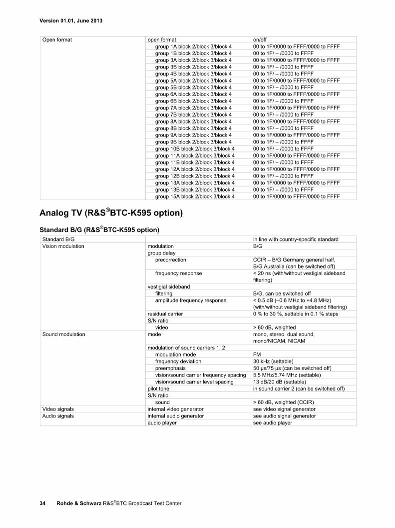
Open format open format on/off group 1A block 2/block 3/block 4 00 to 1F/0000 to FFFF/0000 to FFFF group 1B block 2/block 3/block 4 00 to 1F/ – /0000 to FFFF group 3A block 2/block 3/block 4 00 to 1F/0000 to FFFF/0000 to FFFF group 3B block 2/block 3/block 4 00 to 1F/ – /0000 to FFFF group 4B block 2/block 3/block 4 00 to 1F/ – /0000 to FFFF group 5A block 2/block 3/block 4 00 to 1F/0000 to FFFF/0000 to FFFF group 5B block 2/block 3/block 4 00 to 1F/ – /0000 to FFFF group 6A block 2/block 3/block 4 00 to 1F/0000 to FFFF/0000 to FFFF group 6B block 2/block 3/block 4 00 to 1F/ – /0000 to FFFF group 7A block 2/block 3/block 4 00 to 1F/0000 to FFFF/0000 to FFFF group 7B block 2/block 3/block 4 00 to 1F/ – /0000 to FFFF group 8A block 2/block 3/block 4 00 to 1F/0000 to FFFF/0000 to FFFF group 8B block 2/block 3/block 4 00 to 1F/ – /0000 to FFFF group 9A block 2/block 3/block 4 00 to 1F/0000 to FFFF/0000 to FFFF group 9B block 2/block 3/block 4 00 to 1F/ – /0000 to FFFF group 10B block 2/block 3/block 4 00 to 1F/ – /0000 to FFFF group 11A block 2/block 3/block 4 00 to 1F/0000 to FFFF/0000 to FFFF group 11B block 2/block 3/block 4 00 to 1F/ – /0000 to FFFF group 12A block 2/block 3/block 4 00 to 1F/0000 to FFFF/0000 to FFFF group 12B block 2/block 3/block 4 00 to 1F/ – /0000 to FFFF group 13A block 2/block 3/block 4 00 to 1F/0000 to FFFF/0000 to FFFF group 13B block 2/block 3/block 4 00 to 1F/ – /0000 to FFFF group 15A block 2/block 3/block 4 00 to 1F/0000 to FFFF/0000 to FFFF
Analog TV (R&S®BTC-K595 option)
Standard B/G (R&S®BTC-K595 option) Standard B/G in line with country-specific standard Vision modulation modulation B/G
group delay precorrection CCIR – B/G Germany general half,
B/G Australia (can be switched off) frequency response < 20 ns (with/without vestigial sideband
filtering) vestigial sideband
filtering B/G, can be switched off amplitude frequency response < 0.5 dB (–0.6 MHz to +4.8 MHz)
(with/without vestigial sideband filtering) residual carrier 0 % to 30 %, settable in 0.1 % steps S/N ratio
video > 60 dB, weighted Sound modulation mode mono, stereo, dual sound,
mono/NICAM, NICAM modulation of sound carriers 1, 2
modulation mode FM frequency deviation 30 kHz (settable) preemphasis 50 µs/75 µs (can be switched off) vision/sound carrier frequency spacing 5.5 MHz/5.74 MHz (settable) vision/sound carrier level spacing 13 dB/20 dB (settable)
pilot tone in sound carrier 2 (can be switched off) S/N ratio
sound > 60 dB, weighted (CCIR) Video signals internal video generator see video signal generator Audio signals internal audio generator see audio signal generator
audio player see audio player
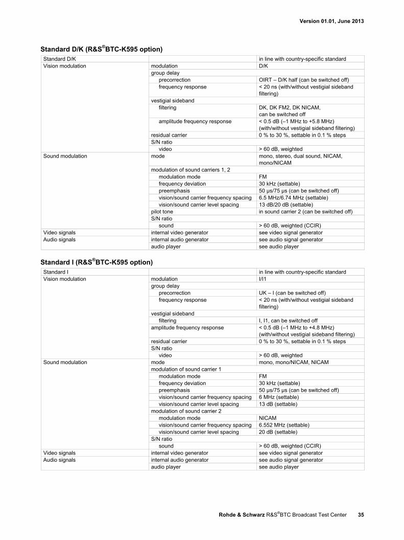
Version 01.01, June 2013
Rohde & Schwarz R&S®BTC Broadcast Test Center 35
Standard D/K (R&S®BTC-K595 option) Standard D/K in line with country-specific standard Vision modulation modulation D/K
group delay precorrection OIRT – D/K half (can be switched off) frequency response < 20 ns (with/without vestigial sideband
filtering) vestigial sideband
filtering DK, DK FM2, DK NICAM, can be switched off
amplitude frequency response < 0.5 dB (–1 MHz to +5.8 MHz) (with/without vestigial sideband filtering)
residual carrier 0 % to 30 %, settable in 0.1 % steps S/N ratio
video > 60 dB, weighted Sound modulation mode mono, stereo, dual sound, NICAM,
mono/NICAM modulation of sound carriers 1, 2
modulation mode FM frequency deviation 30 kHz (settable) preemphasis 50 µs/75 µs (can be switched off) vision/sound carrier frequency spacing 6.5 MHz/6.74 MHz (settable) vision/sound carrier level spacing 13 dB/20 dB (settable)
pilot tone in sound carrier 2 (can be switched off) S/N ratio
sound > 60 dB, weighted (CCIR) Video signals internal video generator see video signal generator Audio signals internal audio generator see audio signal generator
audio player see audio player
Standard I (R&S®BTC-K595 option) Standard I in line with country-specific standard Vision modulation modulation I/I1
group delay precorrection UK – I (can be switched off) frequency response < 20 ns (with/without vestigial sideband
filtering) vestigial sideband
filtering I, I1, can be switched off amplitude frequency response < 0.5 dB (–1 MHz to +4.8 MHz)
(with/without vestigial sideband filtering) residual carrier 0 % to 30 %, settable in 0.1 % steps S/N ratio
video > 60 dB, weighted Sound modulation mode mono, mono/NICAM, NICAM
modulation of sound carrier 1 modulation mode FM frequency deviation 30 kHz (settable) preemphasis 50 µs/75 µs (can be switched off) vision/sound carrier frequency spacing 6 MHz (settable) vision/sound carrier level spacing 13 dB (settable)
modulation of sound carrier 2 modulation mode NICAM vision/sound carrier frequency spacing 6.552 MHz (settable) vision/sound carrier level spacing 20 dB (settable)
S/N ratio sound > 60 dB, weighted (CCIR)
Video signals internal video generator see video signal generator Audio signals internal audio generator see audio signal generator
audio player see audio player
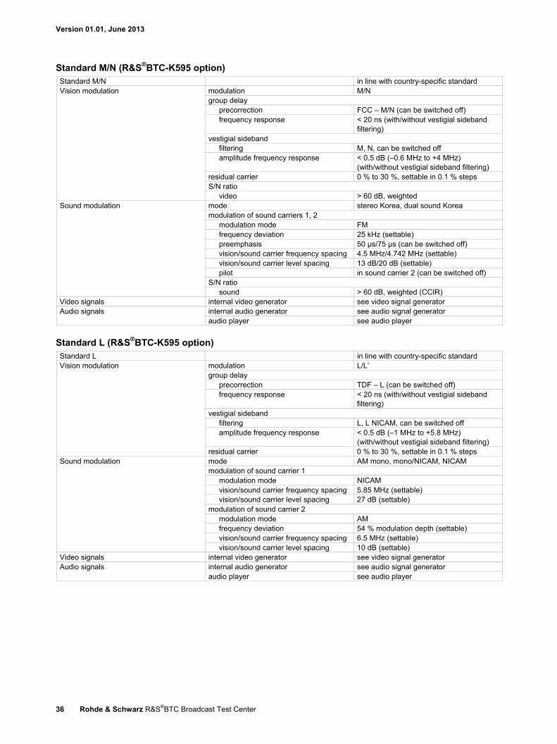
Version 01.01, June 2013
36 Rohde & Schwarz R&S®BTC Broadcast Test Center
Standard M/N (R&S®BTC-K595 option) Standard M/N in line with country-specific standard Vision modulation modulation M/N
group delay precorrection FCC – M/N (can be switched off) frequency response < 20 ns (with/without vestigial sideband
filtering) vestigial sideband
filtering M, N, can be switched off amplitude frequency response < 0.5 dB (–0.6 MHz to +4 MHz)
(with/without vestigial sideband filtering) residual carrier 0 % to 30 %, settable in 0.1 % steps S/N ratio
video > 60 dB, weighted Sound modulation mode stereo Korea, dual sound Korea
modulation of sound carriers 1, 2 modulation mode FM frequency deviation 25 kHz (settable) preemphasis 50 µs/75 µs (can be switched off) vision/sound carrier frequency spacing 4.5 MHz/4.742 MHz (settable) vision/sound carrier level spacing 13 dB/20 dB (settable) pilot in sound carrier 2 (can be switched off)
S/N ratio sound > 60 dB, weighted (CCIR)
Video signals internal video generator see video signal generator Audio signals internal audio generator see audio signal generator
audio player see audio player
Standard L (R&S®BTC-K595 option) Standard L in line with country-specific standard Vision modulation modulation L/L’
group delay precorrection TDF – L (can be switched off) frequency response < 20 ns (with/without vestigial sideband
filtering) vestigial sideband
filtering L, L NICAM, can be switched off amplitude frequency response < 0.5 dB (–1 MHz to +5.8 MHz)
(with/without vestigial sideband filtering) residual carrier 0 % to 30 %, settable in 0.1 % steps
Sound modulation mode AM mono, mono/NICAM, NICAM modulation of sound carrier 1
modulation mode NICAM vision/sound carrier frequency spacing 5.85 MHz (settable) vision/sound carrier level spacing 27 dB (settable)
modulation of sound carrier 2 modulation mode AM frequency deviation 54 % modulation depth (settable) vision/sound carrier frequency spacing 6.5 MHz (settable) vision/sound carrier level spacing 10 dB (settable)
Video signals internal video generator see video signal generator Audio signals internal audio generator see audio signal generator
audio player see audio player
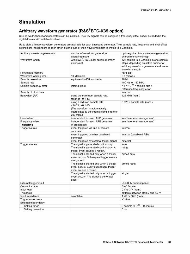
Version 01.01, June 2013
Rohde & Schwarz R&S®BTC Broadcast Test Center 37
Simulation
Arbitrary waveform generator (R&S®BTC-K35 option) One or two I/Q baseband generators can be installed. Their I/Q signals can be assigned a frequency offset and/or be added in the digital domain with settable level ratio.
Up to eight arbitrary waveform generators are available for each baseband generator. Their sample rate, frequency and level offset settings are independent of each other, but the sum of their waveform length is limited to 1 Gsample.
Arbitrary waveform generators number of waveform generators up to eight arbitrary waveform generators operating mode shared memory concept
Waveform length with R&S®BTC-B3004 option (memory extension)
128 sample to 1 Gsample in one-sample steps, depending on active number of arbitrary waveform generators and loaded waveform length
Nonvolatile memory hard disk Waveform loading time 10 Msample 5 s (meas.) Sample resolution equivalent to D/A converter 16 bit Sample rate 400 Hz to 160 MHz Sample frequency error internal clock < 5 × 10⁻¹⁴ × sample rate +
reference frequency error Sample clock source internal Bandwidth (RF) using the maximum sample rate,
rolloff to –0.1 dB 125 MHz (nom.)
using a reduced sample rate, rolloff to –0.1 dB (The waveform is automatically interpolated to the internal sample rate of 200 MHz.)
0.625 × sample rate (nom.)
Level offset independent for each ARB generator see “Interferer management” Frequency offset independent for each ARB generator see ”Interferer management” Triggering in preparation Trigger source event triggered via GUI or remote
command internal
event triggered by other baseband generator
internal (baseband A/B)
event triggered by external trigger signal external Trigger modes The signal is generated continuously. auto
The signal is generated continuously. A trigger event causes a restart.
retrig
The signal is started only when a trigger event occurs. Subsequent trigger events are ignored.
armed auto
The signal is started only when a trigger event occurs. Every subsequent trigger event causes a restart.
armed retrig
The signal is started only when a trigger event occurs. The signal is generated once.
single
External trigger input USER IN on front panel Connector type BNC female Input level 0 V to 3 V (nom.) Threshold settable between 10 mV and 1.9 V Input impedance selectable 1 kΩ or 50 Ω (nom.) Trigger uncertainty ±2.5 ns External trigger delay
Setting range 0 sample to (216 – 1) sample Setting resolution 5 ns

Version 01.01, June 2013
38 Rohde & Schwarz R&S®BTC Broadcast Test Center
Interferer management The interferer management functionality is included in the R&S®BTC-K35 arbitrary waveform generator option.
Interferer signal sources arbitrary waveform generator up to eight interference signals digital I/Q IN external I/Q signal
bandwidth < ±80 MHz level offset range –60 dB to +60 dB
(relative to useful signal level) 26 frequency offset range –80 MHz to +80 MHz
(relative to center frequency) routing selection for adding interferer signals
to TX distortion, to fading, to noise, to RX distortion
Signal set activated options, waveforms and interferers, user-specific waveforms
Distortion simulation and nonlinearity (R&S®BTC-K1200)
TX distortion simulation Transmission distortion simulation can be generated either on path A or B with one R&S®BTC-K1200 option. For transmission distortion simulation to be generated on paths A and B simultaneously, two R&S®BTC-K1200 must be installed.
TX distortion simulation Nonlinear distortion limiter
limiter position 0 % to 100 %, settable nonlinearity
gain –50 % to +50 % deviation, settable phase –10° to +10° deviation, settable number of nodes 16 curve interpolation cubic spline
entry by curve table curves can be loaded file format text
Linear distortion filter function complex FIR number of taps 128, real and imaginary coefficient bit width 18 number of nodes 16 filter design internal filter design method windowed FIR taps can be loaded file format text entry by curve table
RX distortion simulation (in preparation) Receiving distortion simulation can be generated either on path A or B with one R&S®BTC-K1200 option. For receiving distortion simulation to be generated on paths A and B simultaneously, two R&S®BTC-K1200 must be installed.
RX distortion simulation Nonlinear distortion limiter
limiter position 0 % to 100 %, settable nonlinearity
gain –50 % to +50 % deviation, settable phase –10° to +10° deviation, settable number of nodes 16 curve interpolation cubic spline
entry by curve table curves can be loaded file format text
26 High interferer power diminishes useful signal values.

Version 01.01, June 2013
Rohde & Schwarz R&S®BTC Broadcast Test Center 39
Linear distortion filter function complex FIR number of taps 128, real and imaginary coefficient bit width 18 number of nodes 16 filter design internal filter design method windowed FIR taps can be loaded file format text entry by curve table
IMUX/OMUX simulation (in preparation) IMUX/OMUX simulation can be generated either on path A or B with one R&S®BTC-K1200 option. For IMUX/OMUX simulation to be generated on paths A and B simultaneously, two R&S®BTC-K1200 must be installed.
IMUX/OMUX simulation specification in preparation
Fading simulator (R&S®BTC-B1031, R&S®BTC-B1032 and R&S®BTC-B1034 options) All frequency and time settings are coupled to the internal reference frequency.
Number of installed fading simulators R&S®BTC-B1031 1 R&S®BTC-B1031 and R&S®BTC-B1032 2 R&S®BTC-B1031, R&S®BTC-B1032 and R&S®BTC-B1034
4
Number of fading paths (per simulator) SISO 40 MIMO 20
Start seed 0 to 9 Fading profiles static path, pure Doppler, Rayleigh, Rice,
constant phase Fading profile parameter
Rayleigh pseudo-noise interval > 1 year Constant phase phase 0° to 360°
phase resolution 1° Pure Doppler maximum resulting Doppler shift frequency ratio × current Doppler
frequency frequency ratio –1 to +1 resolution 0.01
Rician combination of Rayleigh and pure Doppler power ratio –30 dB to +30 dB
Fading path loss setting range 0 dB to 50 dB resolution 0.01 dB accuracy < 0.01 dB
Fading path delay The 40 (SISO) / 20 (MIMO) fading paths are divided in 8 (SISO) / 4 (MIMO) path groups. Each group consists of 3 fine delay and 2 standard delay paths. A basic delay can be set per path group and an additional delay per path. The total delay per path is the sum of the basic delay of the respective group and of the additional delay of the path.
Basic delay per group group 1 0 s group 2, 3, 4 0 s to 0.5 s resolution 5 ns
Additional delay per path fine delay path setting range 0 µs to 20 µs fine delay path resolution 2.5 ps standard delay path setting range 0 µs to 20 µs standard delay path resolution 5 ns
Speed range at f = 1 GHz 0 km/h to 4320 km/h accuracy < 0.1 %
Doppler frequency setting range 0 Hz to 4000 Hz accuracy < 0.1 %
Restart standard auto, manual, external Total insertion loss automatic or user-definable, with clipping
indicator –3 dB to 30 dB

Version 01.01, June 2013
40 Rohde & Schwarz R&S®BTC Broadcast Test Center
Correlation fading paths in signal path A pairwise with fading paths in signal path B correlation coefficient
setting range 0 % to 100 % resolution 1 %
correlation phase setting range 0° to 360° resolution 1°
Lognormal standard deviation 0 dB to 12 dB resolution 1 dB local constant at f = 1 GHz 20 m to 2000 m
Dynamic fading (R&S®BTC-K1031 option; in preparation) At least one fading simulator must be installed. If two or more fading simulators are installed (signal paths A and B), dynamic fading can be used either on signal path A or B with one R&S®BTC-K1031 option. For dynamic fading to be used on signal paths A and B simultaneously, two R&S®BTC-K1031 must be installed.
Moving delay mode Number of fading paths 2 per signal path Fading profiles none Basic delay in steps of 5 ns 0 s to 0.5 s Delay variation peak to peak 0.3 µs to 40 µs
variation period 10 s to 500 s variation speed 0 µs/s to 5 µs/s
Delay step size 5 ps Birth-death mode System bandwidth 160 MHz Number of fading paths 2 per signal path Fading profiles pure Doppler Delay range 0 s to 40 µs Delay grid 0 s to 20 µs 27 Positions 3 to 50 27 Hopping dwell 100 ms to 5 s
Start offset separately settable for each signal path 1 ms to 200 ms Delay resolution 10 ns Two-channel interferer Number of fading paths 2 per signal path Fading profiles static path, pure Doppler, Rayleigh Fading profile parameter
Rayleigh pseudo-noise interval > 1 year phase resolution 1°
Pure Doppler maximum resulting Doppler shift frequency ratio × current Doppler frequency
frequency ratio –1 to +1 resolution 0.01
Fading path loss setting range 0 dB to 50 dB resolution 0.01 dB accuracy < 0.01 dB
Speed range at f = 1 GHz 0 km/h to 4320 km/h accuracy < 0.1 %
Min. delay path 1 0 µs to 1638 µs path 2 0 µs to 999.9 µs
Max. delay path 1 n.a. path 2 0.1 µs to 1000 µs
Moving mode path 1 n.a. path 2 sliding, hopping
Period/dwell 0.1 s to 10 s
27 The maximum delay range of 40 µs cannot be exceeded.

Version 01.01, June 2013
Rohde & Schwarz R&S®BTC Broadcast Test Center 41
Extended statistic functions (R&S®BTC-K1032 option) At least one fading simulator must be installed. If two or more fading simulators are installed (signal paths A and B), extended statistic functions can be used either on signal path A or B with one R&S®BTC-K1032 option. For extended statistic functions to be used on signal paths A and B simultaneously, two R&S®BTC-K1032 must be installed.
Fading profiles Gauss I, Gauss II sum of two Gaussian distributions in line with DAB standard Gauss DAB 1, Gauss DAB 2 Gaussian distribution, shifted in frequency in line with DAB standard WiMAX™ Doppler rounded Doppler PSD model in line with IEEE 802.16a-03-01 WiMAX™ Rice same as WiMAX™ Doppler plus pure
Doppler in line with IEEE 802.16a-03-01
Predefined settings DAB-RA, DAB-TU, DAB-SFN in line with EN 50248-2001
MIMO fading (R&S®BTC-K1034 option; in preparation) The R&S®BTC-K1034 option allows up to 16 fading channels to be simulated as is required for 4x4 MIMO receiver tests. At least two fading simulators must be installed (signal paths A and B) and two baseband sources (R&S®BTC-B1 and R&S®BTC-B2) must be present.
Number of signal paths with two fading simulator options 2 with four fading simulator options 2 to 4
2x2 MIMO Signal routing 2x2 MIMO, simulating fading channels
between two TX and two RX antennas A A B B
input always split output sum of two signal paths
Steering matrix can be set by setting the diagonal elements of the correlation matrix Correlation Correlation between corresponding fading paths of the four signal paths can be set in a
correlation matrix. For each fading path index, an individual matrix can be set. correlation coefficient
setting range 0 % to 100 % resolution 1 %
correlation phase setting range 0° to 360° resolution 1°
Correlation matrix setting individually or with Kronecker assumption (RX and TX antenna correlation with automatic calculation of matrix)
Matrix representation (real, imaginary) or (magnitude, phase)
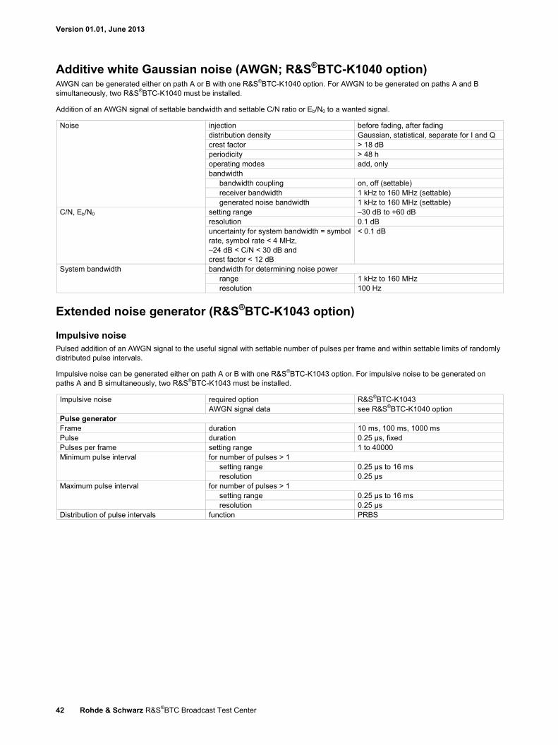
Version 01.01, June 2013
42 Rohde & Schwarz R&S®BTC Broadcast Test Center
Additive white Gaussian noise (AWGN; R&S®BTC-K1040 option) AWGN can be generated either on path A or B with one R&S®BTC-K1040 option. For AWGN to be generated on paths A and B simultaneously, two R&S®BTC-K1040 must be installed.
Addition of an AWGN signal of settable bandwidth and settable C/N ratio or Eb/N0 to a wanted signal.
Noise injection before fading, after fading distribution density Gaussian, statistical, separate for I and Q crest factor > 18 dB periodicity > 48 h operating modes add, only bandwidth
bandwidth coupling on, off (settable) receiver bandwidth 1 kHz to 160 MHz (settable) generated noise bandwidth 1 kHz to 160 MHz (settable)
C/N, Eb/N0 setting range −30 dB to +60 dB resolution 0.1 dB uncertainty for system bandwidth = symbol rate, symbol rate < 4 MHz, –24 dB < C/N < 30 dB and crest factor < 12 dB
< 0.1 dB
System bandwidth bandwidth for determining noise power range 1 kHz to 160 MHz resolution 100 Hz
Extended noise generator (R&S®BTC-K1043 option)
Impulsive noise Pulsed addition of an AWGN signal to the useful signal with settable number of pulses per frame and within settable limits of randomly distributed pulse intervals.
Impulsive noise can be generated either on path A or B with one R&S®BTC-K1043 option. For impulsive noise to be generated on paths A and B simultaneously, two R&S®BTC-K1043 must be installed.
Impulsive noise required option R&S®BTC-K1043 AWGN signal data see R&S®BTC-K1040 option
Pulse generator Frame duration 10 ms, 100 ms, 1000 ms Pulse duration 0.25 µs, fixed Pulses per frame setting range 1 to 40000 Minimum pulse interval for number of pulses > 1
setting range 0.25 µs to 16 ms resolution 0.25 µs
Maximum pulse interval for number of pulses > 1 setting range 0.25 µs to 16 ms resolution 0.25 µs
Distribution of pulse intervals function PRBS
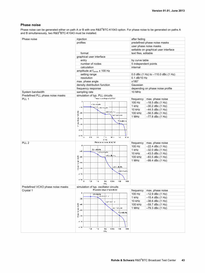
Version 01.01, June 2013
Rohde & Schwarz R&S®BTC Broadcast Test Center 43
Phase noise Phase noise can be generated either on path A or B with one R&S®BTC-K1043 option. For phase noise to be generated on paths A and B simultaneously, two R&S®BTC-K1043 must be installed.
Phase noise injection after fading profiles predefined phase noise masks
user phase noise masks settable on graphical user interface
format text files, editable graphical user interface
entry by curve table number of nodes 5 independent points calculation internal
amplitude at fcarrier ± 100 Hz setting range 0.0 dBc (1 Hz) to –110.0 dBc (1 Hz) resolution 0.1 dB/10 Hz
max. phase angle ±180° density distribution function Gaussian frequency response depending on phase noise profile
System bandwidth sampling rate 10 MHz Predefined PLL phase noise masks simulation of typ. PLL circuits PLL 1 frequency max. phase noise
100 Hz –18.5 dBc (1 Hz) 1 kHz –30.2 dBc (1 Hz) 10 kHz –44.5 dBc (1 Hz) 100 kHz –56.5 dBc (1 Hz) 1 MHz –77.8 dBc (1 Hz)
PLL 2 frequency max. phase noise 100 Hz –22.4 dBc (1 Hz) 1 kHz –32.0 dBc (1 Hz) 10 kHz –43.5 dBc (1 Hz) 100 kHz –83.5 dBc (1 Hz) 1 MHz –99.4 dBc (1 Hz)
Predefined VCXO phase noise masks simulation of typ. oscillator circuits Crystal 1 frequency max. phase noise
100 Hz –12.9 dBc (1 Hz) 1 kHz –15.4 dBc (1 Hz) 10 kHz –38.6 dBc (1 Hz) 100 kHz –59.7 dBc (1 Hz) 1 MHz –79.3 dBc (1 Hz)
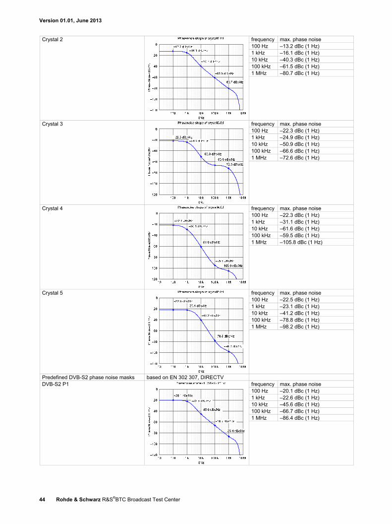
Version 01.01, June 2013
44 Rohde & Schwarz R&S®BTC Broadcast Test Center
Crystal 2 frequency max. phase noise 100 Hz –13.2 dBc (1 Hz) 1 kHz –16.1 dBc (1 Hz) 10 kHz –40.3 dBc (1 Hz) 100 kHz –61.5 dBc (1 Hz) 1 MHz –80.7 dBc (1 Hz)
Crystal 3 frequency max. phase noise 100 Hz –22.3 dBc (1 Hz) 1 kHz –24.9 dBc (1 Hz) 10 kHz –50.9 dBc (1 Hz) 100 kHz –66.6 dBc (1 Hz) 1 MHz –72.6 dBc (1 Hz)
Crystal 4 frequency max. phase noise 100 Hz –22.3 dBc (1 Hz) 1 kHz –31.1 dBc (1 Hz) 10 kHz –61.6 dBc (1 Hz) 100 kHz –59.5 dBc (1 Hz) 1 MHz –105.8 dBc (1 Hz)
Crystal 5 frequency max. phase noise 100 Hz –22.5 dBc (1 Hz) 1 kHz –23.1 dBc (1 Hz) 10 kHz –41.2 dBc (1 Hz) 100 kHz –78.8 dBc (1 Hz) 1 MHz –98.2 dBc (1 Hz)
Predefined DVB-S2 phase noise masks based on EN 302 307, DIRECTV DVB-S2 P1 frequency max. phase noise
100 Hz –20.1 dBc (1 Hz) 1 kHz –22.6 dBc (1 Hz) 10 kHz –45.6 dBc (1 Hz) 100 kHz –66.7 dBc (1 Hz) 1 MHz –86.4 dBc (1 Hz)
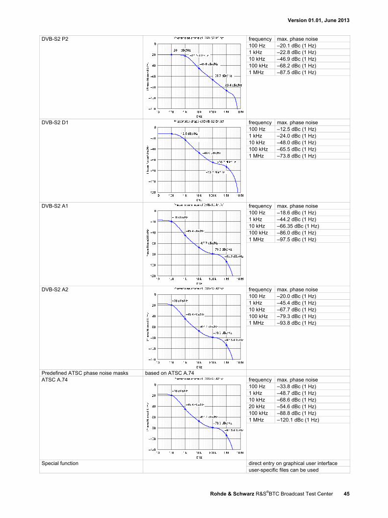
Version 01.01, June 2013
Rohde & Schwarz R&S®BTC Broadcast Test Center 45
DVB-S2 P2 frequency max. phase noise 100 Hz –20.1 dBc (1 Hz) 1 kHz –22.8 dBc (1 Hz) 10 kHz –46.9 dBc (1 Hz) 100 kHz –68.2 dBc (1 Hz) 1 MHz –87.5 dBc (1 Hz)
DVB-S2 D1 frequency max. phase noise 100 Hz –12.5 dBc (1 Hz) 1 kHz –24.0 dBc (1 Hz) 10 kHz –48.0 dBc (1 Hz) 100 kHz –65.5 dBc (1 Hz) 1 MHz –73.8 dBc (1 Hz)
DVB-S2 A1 frequency max. phase noise 100 Hz –18.6 dBc (1 Hz) 1 kHz –44.2 dBc (1 Hz) 10 kHz –66.35 dBc (1 Hz) 100 kHz –86.0 dBc (1 Hz) 1 MHz –97.5 dBc (1 Hz)
DVB-S2 A2 frequency max. phase noise 100 Hz –20.0 dBc (1 Hz) 1 kHz –45.4 dBc (1 Hz) 10 kHz –67.7 dBc (1 Hz) 100 kHz –79.3 dBc (1 Hz) 1 MHz –93.8 dBc (1 Hz)
Predefined ATSC phase noise masks based on ATSC A.74 ATSC A.74
frequency max. phase noise 100 Hz –33.8 dBc (1 Hz) 1 kHz –48.7 dBc (1 Hz) 10 kHz –68.6 dBc (1 Hz) 20 kHz –54.6 dBc (1 Hz) 100 kHz –88.8 dBc (1 Hz) 1 MHz –120.1 dBc (1 Hz)
Special function direct entry on graphical user interface user-specific files can be used
Version 01.01, June 2013
46 Rohde & Schwarz R&S®BTC Broadcast Test Center
Analysis
TS analyzer (in preparation) The transport stream analyzer is included in the multimedia generator suite and can also be used for transport stream analysis independently of the multimedia generator suite.
Transport stream analyzer for MPEG-2 transport streams specification in preparation
BER measurements (R&S®BTC-K2060 option) The bit error rate meter counts the errored bits in a data stream and displays the absolute error count and the relative error count referenced to the total number of received bits. It is possible to analyze serial data streams or MPEG-2 transport streams.
At least one I/Q baseband generator (R&S®BTC-B1 option) is required for using the rear panel TS SERIAL IN or IP (1000BaseT) interface.
BER measurements for all digital modulation modes Display measured value BER
error count measurement time
Control manual start, restart, stop Gating time automatic depending on bit error rate
user-defined time window (1 s to 100 h), single run, infinite
Logging control on/off/reset text display, log file all measured values and error events
PRBS measurements Inputs for BER clock, BER data, BER enable
connectors BNC female, USER 4, 5, 6 on rear panel input impedance selectable, 1 kΩ or 50 Ω input level 0 V to 3 V (nom.) threshold settable between 10 mV and 1.9 V
BER data input data rate up to 90 Mbit/s PRBS 223–1/215–1 (in line with ITU-T O.151)
BER clock, BER data polarity normal, inverted BER enable always, active high, active low MPEG-2 TS measurements Input input interfaces ASI, SMPTE 310, IP (see "Digital
audio/video interfaces") input signal TS packet packet length 188, 204, 208 payload (PRBS in line with ITU-T O.151) PRBS 223–1/215–1, constant 0x00/0xFF PID NULL (1FFF (hex)), settable (0 to
1FFF(hex)), don’t care
Version 01.01, June 2013
Rohde & Schwarz R&S®BTC Broadcast Test Center 47
Analyzer modules The R&S®BTC can also be equipped with analyzer modules from the R&S®VTx family. The number of modules that can be installed and used depends on the number of free slots on the R&S®BTC. For more information about the individual hardware options, see the R&S®VTC/VTE/VTS specifications (PD 3606.7776.22).
MHL™ RX/TX (R&S®VT-B2350 option) R&S®VT module for analyzing MHL™ interface signals.
MHL™ RX/TX (R&S®VT-B2351 option) R&S®VT module for analyzing MHL™ interface signals conforming to the MHL specifications version 2.0.
HDMI™ RX 225 MHz (R&S®VT-B2360 option) R&S®VT module for analyzing high-definition multimedia interface signals.
HDMI™ RX 300 MHz (R&S®VT-B2361 option) R&S®VT module for analyzing high-definition multimedia interface signals.
Analog AV RX (R&S®VT-B2370 option) R&S®VT module for analyzing analog component or composite signals.
Analyzer software options In addition to the above-mentioned analyzer modules from the R&S®VTx family, other software options can also be installed on the R&S®BTC. These software options make it possible to measure the relevant signals.
MHL™ CTS system sink test (R&S®VT-K355 option) R&S®VT software option for sink testing in line with the MHL™ compliance test specification (CTS) 1.2.
MHL™ CTS system source test (R&S®VT-K2355 option) R&S®VT software option for source testing in line with the MHL™ compliance test specification (CTS) 1.2.
Video analysis (R&S®VT-K2100 option) R&S®VT software option for video signal analysis and measurement of level, timing and color.
Video measurements (R&S®VT-K2101 option) R&S®VT software option for measuring composite and component video signals.
AV inspection (R&S®VT-K2110 option) R&S®VT software option with basic A/V difference analysis functionality.
AV distortion analysis (R&S®VT-K2111 option) R&S®VT software option with enhanced A/V difference analysis functionality.
Audio analysis (R&S®VT-K2150 option) R&S®VT software option with enhanced A/V difference analysis functionality.
Version 01.01, June 2013
48 Rohde & Schwarz R&S®BTC Broadcast Test Center
Automated testing Additional analyzer modules from the R&S®VTx family can be installed. The number of modules that can be installed and used depends on the number of free slots on the R&S®BTC.
For more information about the individual hardware options, see the R&S®VTC specifications (PD 3606.7776.22).
R&S®AVBrun sequencer software tools The R&S®BTC supports test suites for different test standards. These suites can be used together with the R&S®AVBrun test sequencer software for automated test sequences.
D-Book test suite (R&S®BTC-KT3310 option) Test suite with a wide range of test cases based on the DTG D-Book.
NorDig test suite (R&S®BTC-KT3311 option) Test suite with a wide range of test cases based on the NorDig Unified Test Specification.
E-Book test suite (R&S®BTC-KT3312 option) Test suite with a wide range of test cases based on the DTG E-Book.
A/V distortion test (R&S®VT-KT3360 option) Option for automated PFP measurements using the D-Book, NorDig and E-Book test suites.
For more information about the individual test suites, see the relevant test suite specifications.
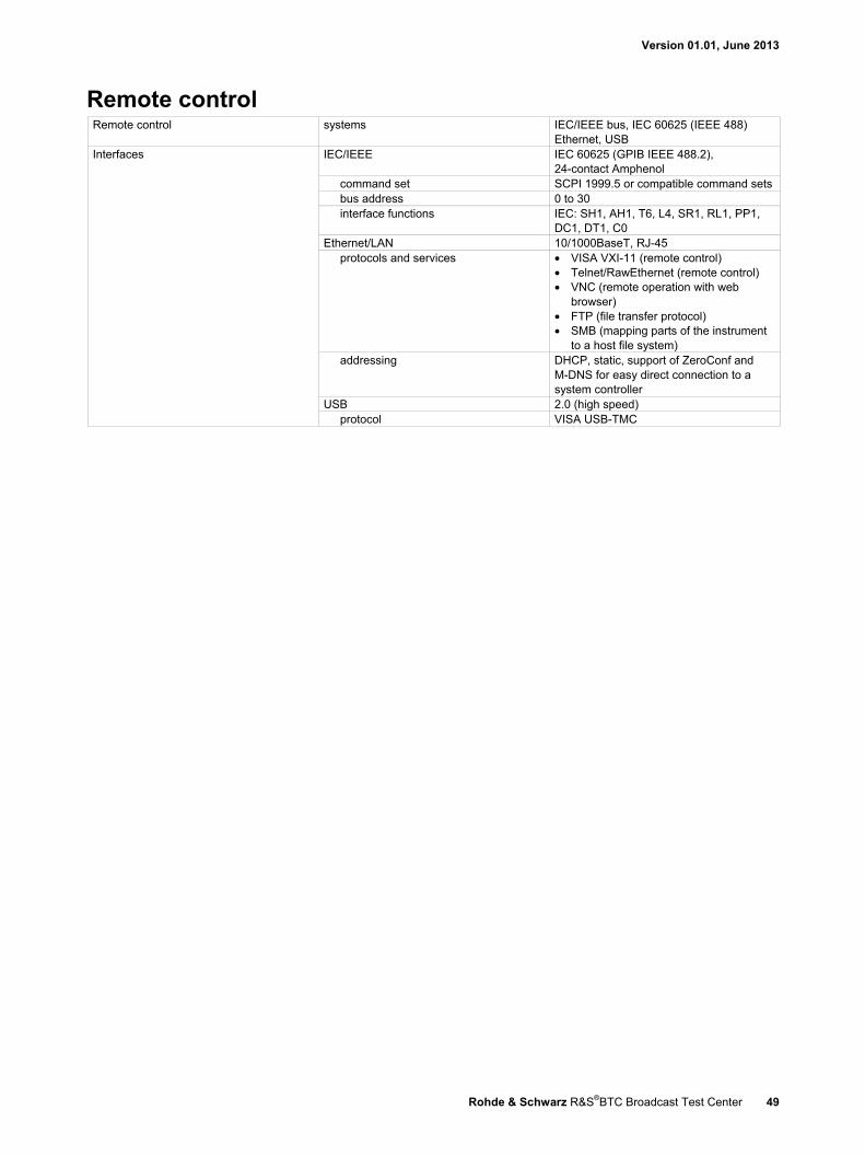
Version 01.01, June 2013
Rohde & Schwarz R&S®BTC Broadcast Test Center 49
Remote control Remote control systems IEC/IEEE bus, IEC 60625 (IEEE 488)
Ethernet, USB Interfaces IEC/IEEE IEC 60625 (GPIB IEEE 488.2),
24-contact Amphenol command set SCPI 1999.5 or compatible command sets bus address 0 to 30 interface functions IEC: SH1, AH1, T6, L4, SR1, RL1, PP1,
DC1, DT1, C0 Ethernet/LAN 10/1000BaseT, RJ-45
protocols and services
• VISA VXI-11 (remote control) • Telnet/RawEthernet (remote control) • VNC (remote operation with web
browser) • FTP (file transfer protocol) • SMB (mapping parts of the instrument
to a host file system) addressing DHCP, static, support of ZeroConf and
M-DNS for easy direct connection to a system controller
USB 2.0 (high speed) protocol VISA USB-TMC

Version 01.01, June 2013
50 Rohde & Schwarz R&S®BTC Broadcast Test Center
Connectors
Front panel connectors The following connectors are located on the front panel of the instrument.
RF 50 Ω (path A) RF output path A N female RF 50 Ω (path B) RF output path B N female I (path A) I modulation input signal, path A BNC female Q (path A) Q modulation input signal, path A BNC female I (path B) I modulation input signal, path B BNC female Q (path B) Q modulation input signal, path B BNC female TS serial in 1, TS serial in 2, user-configurable inputs or outputs,
serial transport stream inputs (ASI or SMPTE-310)
BNC female
User in/out trigger input or marker output SENSOR connector for R&S®NRP-Zxx power sensor 6-pin ODU mini-snap series B USB USB 2.0 connector for external USB
devices such as mouse, keyboard, R&S®NRP-Zxx power sensors (with R&S®NRP-Z4 adapter cable), memory stick for software update and data exchange, or USB serial adapter for RS-232 remote control
USB type A
Rear panel connectors Base unit frame REF IN reference frequency input BNC female REF OUT reference frequency output BNC female INST TRG A trigger input for RF path A, e.g. for
frequency or level sweep BNC female
INST TRG B trigger input for RF path B, e.g. for frequency or level sweep
BNC female
USER 4, USER 5, USER 6 user-configurable inputs or outputs, used for serial BER option (R&S®BTC-K2060)
BNC female
EFC input for electronic tuning of internal reference frequency
BNC female
LO IN phase-coherent LO input SMA female LO OUT phase-coherent LO output SMA female IEEE 488 remote control of instrument via GPIB 24-pin Amphenol series 57 female PC module DISPLAY PORT output for external monitor DVI output for external monitor LAN provides remote control functionality and
other services, see "Remote control" RJ-45
USB IN USB 2.0 (high speed) remote control of instrument (USB-TMC)
USB type B
USB DEVICE USB 2.0 (high speed) connector for external USB devices, mouse and keyboard for enhanced operation, R&S®NRP-Zxx power sensors (with R&S®NRP-Z4 adapter cable) for external power measurements and level adjustment of instrument, memory stick for software update and data exchange, USB serial adapter for RS-232 remote control
USB type A
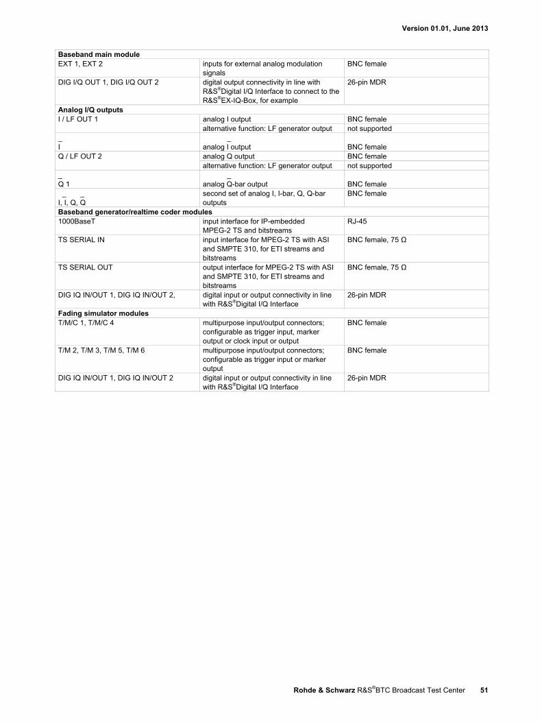
Version 01.01, June 2013
Rohde & Schwarz R&S®BTC Broadcast Test Center 51
Baseband main module EXT 1, EXT 2 inputs for external analog modulation
signals BNC female
DIG I/Q OUT 1, DIG I/Q OUT 2 digital output connectivity in line with R&S®Digital I/Q Interface to connect to the R&S®EX-IQ-Box, for example
26-pin MDR
Analog I/Q outputs I / LF OUT 1 analog I output BNC female
alternative function: LF generator output not supported _ I
_ analog I output
BNC female
Q / LF OUT 2 analog Q output BNC female alternative function: LF generator output not supported
_ Q 1
_ analog Q-bar output
BNC female
_ _ I, I, Q, Q
second set of analog I, I-bar, Q, Q-bar outputs
BNC female
Baseband generator/realtime coder modules 1000BaseT input interface for IP-embedded
MPEG-2 TS and bitstreams RJ-45
TS SERIAL IN input interface for MPEG-2 TS with ASI and SMPTE 310, for ETI streams and bitstreams
BNC female, 75 Ω
TS SERIAL OUT output interface for MPEG-2 TS with ASI and SMPTE 310, for ETI streams and bitstreams
BNC female, 75 Ω
DIG IQ IN/OUT 1, DIG IQ IN/OUT 2, digital input or output connectivity in line with R&S®Digital I/Q Interface
26-pin MDR
Fading simulator modules T/M/C 1, T/M/C 4 multipurpose input/output connectors;
configurable as trigger input, marker output or clock input or output
BNC female
T/M 2, T/M 3, T/M 5, T/M 6 multipurpose input/output connectors; configurable as trigger input or marker output
BNC female
DIG IQ IN/OUT 1, DIG IQ IN/OUT 2 digital input or output connectivity in line with R&S®Digital I/Q Interface
26-pin MDR

Version 01.01, June 2013
52 Rohde & Schwarz R&S®BTC Broadcast Test Center
General data Power supply input voltage range, AC, nominal 100 V to 240 V
AC supply frequency 50 Hz to 60 Hz/400 Hz input current max. 7.3 A power factor correction in line with EN 61000-3-2
EMC in line with EN 55011 class B, EN 61326 Immunity to interfering field strength up to 10 V/m Environmental conditions operating temperature range +5 °C to +45 °C,
in line with DIN EN 60068-2-1, DIN EN 60068-2-2
storage temperature range −40 °C to +60 °C, temperature gradient < 5 K/hour
climatic resistance +40 °C, 90 % rel. humidity
in line with DIN EN 60068-2-3
Mechanical resistance Vibration sinusoidal 5 Hz to 150 Hz,
max. 2 g at 55 Hz, 55 Hz to 150 Hz, 0.5 g const., in line with DIN EN 60068-2-6
random 10 Hz to 300 Hz, acceleration 1.2 g (RMS), in line with DIN EN 60068-2-64
Shock in line with DIN EN 60068-2-27, MIL-STD-810E, 40 g shock spectrum
Electrical safety in line with EN 61010-1 Sound pressure level Tambient = +25 °C, distance 1 m typ. 46 dB(A) Dimensions W × H × D 435 mm × 192 mm × 460 mm
(17.1 in × 7.6 in × 18.1 in) Weight fully equipped 21 kg (46.3 lb) Recommended calibration interval 3 years

Version 01.01, June 2013
Rohde & Schwarz R&S®BTC Broadcast Test Center 53
Ordering information Designation Type Order No. Broadcast Test Center 28 including power cable, quick start guide and CD-ROM (with operating and service manual)
R&S®BTC 2114.3000.02
Options Frequency options Low Phase Noise R&S®BTC-B3100 2114.6000.02 RF Path A
100 kHz to 3 GHz R&S®BTC-B3103 2114.3100.02 100 kHz to 6 GHz R&S®BTC-B3106 2114.3200.02
RF Path B 100 kHz to 3 GHz R&S®BTC-B3203 2114.3300.02 100 kHz to 6 GHz R&S®BTC-B3206 2114.3400.02
Baseband main modules Baseband Main Module, one I/Q path to RF R&S®BTC-B11 2114.6500.02 Baseband Main Module, two I/Q paths to RF R&S®BTC-B12 2114.6600.02 Baseband Baseband Generator, 1st channel R&S®BTC-B1 2114.3500.02 Baseband Generator, 2nd channel R&S®BTC-B2 2114.3600.02 Extended I/Q Interfaces R&S®BTC-K2500 2114.7293 Audio/video generation Multimedia Generator Suite R&S®BTC-K20 included in base unit DVB-T2 Multiprofile Gateway R&S®BTC-K24 in preparation Transmission standards DVB-T2 Coder R&S®BTC-K516 2114.7035 DVB-T/DVB-H Coder R&S®BTC-K501 2114.6980 DAB/DAB+/T-DMB Coder R&S®BTC-K511 2114.7106 ATSC M/H, 8VSB Coder R&S®BTC-K518 2114.7135 DTMB Coder (GB20600-2006) R&S®BTC-K512 2114.7112 CMMB Coder R&S®BTC-K515 2114.7129 ISDB-T/ISDB-TB/ISDB-TSB Coder R&S®BTC-K506 2114.7087 ISDB-Tmm Coder R&S®BTC-K507 2114.7029 DVB-C2 Coder R&S®BTC-K517 2114.7041 J.83/A/B/C Coder (DVB-C, US Cable, ISDB-C) R&S®BTC-K502 2114.6997 DVB-S/DVB-S2, DSNG Coder R&S®BTC-K508 2114.7093 DIRECTV Legacy Coder R&S®BTC-K509 2114.7270 AM/FM RDS RDBS Coder R&S®BTC-K570 2114.7141 ATV Multistandard Coder R&S®BTC-K595 2114.7287 Transmission simulations Arbitrary Waveform Generator R&S®BTC-K35 2114.6974 Fading Simulator (path A) R&S®BTC-B1031 2114.3700.02 Fading Simulator (path B) R&S®BTC-B1032 2114.3800.02 Fading Simulator Extension (path A and path B) R&S®BTC-B1034 in preparation Dynamic Fading R&S®BTC-K1031 2114.7158 Extended Statistic Functions R&S®BTC-K1032 2114.7164 MIMO Fading R&S®BTC-K1034 in preparation Additive White Gaussian Noise (AWGN) R&S®BTC-K1040 2114.7070 Extended Noise Generator R&S®BTC-K1043 2114.7235 Distortion Simulation R&S®BTC-K1200 2114.7329 BER Measurement R&S®BTC-K2060 2114.7264 Other options Rear Panel Connectors (path A) R&S®BTC-B3121 2114.6300.02 Rear Panel Connectors (path B) R&S®BTC-B3122 2114.6400.02
28 The base unit can only be ordered with an R&S®BTC-B1xx frequency option.
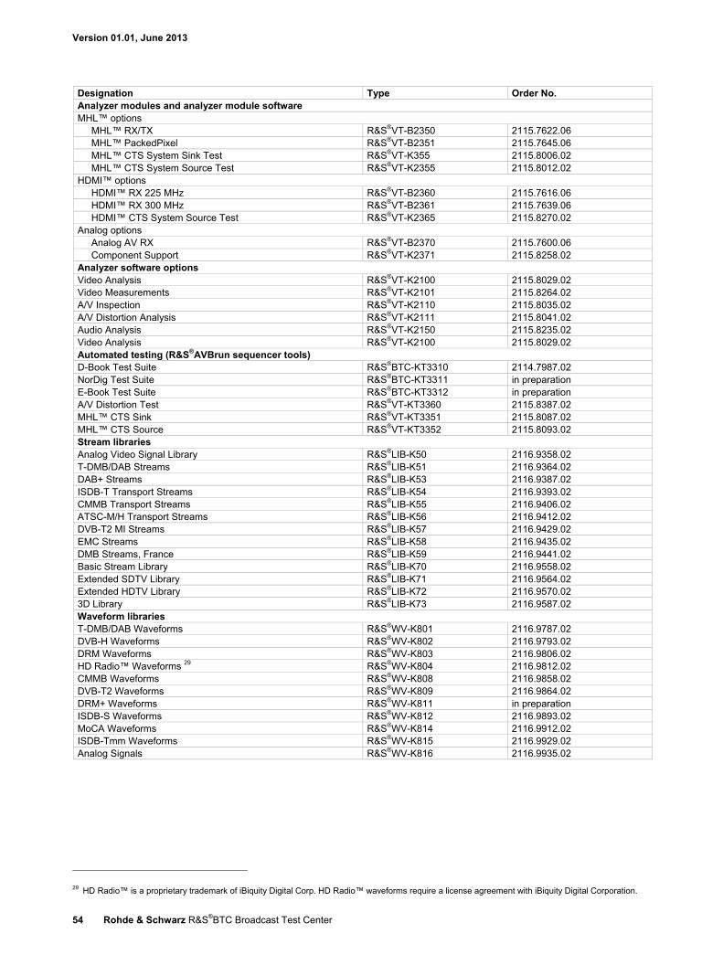
Version 01.01, June 2013
54 Rohde & Schwarz R&S®BTC Broadcast Test Center
Designation Type Order No. Analyzer modules and analyzer module software MHL™ options
MHL™ RX/TX R&S®VT-B2350 2115.7622.06 MHL™ PackedPixel R&S®VT-B2351 2115.7645.06 MHL™ CTS System Sink Test R&S®VT-K355 2115.8006.02 MHL™ CTS System Source Test R&S®VT-K2355 2115.8012.02
HDMI™ options HDMI™ RX 225 MHz R&S®VT-B2360 2115.7616.06 HDMI™ RX 300 MHz R&S®VT-B2361 2115.7639.06 HDMI™ CTS System Source Test R&S®VT-K2365 2115.8270.02
Analog options Analog AV RX R&S®VT-B2370 2115.7600.06 Component Support R&S®VT-K2371 2115.8258.02
Analyzer software options Video Analysis R&S®VT-K2100 2115.8029.02 Video Measurements R&S®VT-K2101 2115.8264.02 A/V Inspection R&S®VT-K2110 2115.8035.02 A/V Distortion Analysis R&S®VT-K2111 2115.8041.02 Audio Analysis R&S®VT-K2150 2115.8235.02 Video Analysis R&S®VT-K2100 2115.8029.02 Automated testing (R&S®AVBrun sequencer tools) D-Book Test Suite R&S®BTC-KT3310 2114.7987.02 NorDig Test Suite R&S®BTC-KT3311 in preparation E-Book Test Suite R&S®BTC-KT3312 in preparation A/V Distortion Test R&S®VT-KT3360 2115.8387.02 MHL™ CTS Sink R&S®VT-KT3351 2115.8087.02 MHL™ CTS Source R&S®VT-KT3352 2115.8093.02 Stream libraries Analog Video Signal Library R&S®LIB-K50 2116.9358.02 T-DMB/DAB Streams R&S®LIB-K51 2116.9364.02 DAB+ Streams R&S®LIB-K53 2116.9387.02 ISDB-T Transport Streams R&S®LIB-K54 2116.9393.02 CMMB Transport Streams R&S®LIB-K55 2116.9406.02 ATSC-M/H Transport Streams R&S®LIB-K56 2116.9412.02 DVB-T2 MI Streams R&S®LIB-K57 2116.9429.02 EMC Streams R&S®LIB-K58 2116.9435.02 DMB Streams, France R&S®LIB-K59 2116.9441.02 Basic Stream Library R&S®LIB-K70 2116.9558.02 Extended SDTV Library R&S®LIB-K71 2116.9564.02 Extended HDTV Library R&S®LIB-K72 2116.9570.02 3D Library R&S®LIB-K73 2116.9587.02 Waveform libraries T-DMB/DAB Waveforms R&S®WV-K801 2116.9787.02 DVB-H Waveforms R&S®WV-K802 2116.9793.02 DRM Waveforms R&S®WV-K803 2116.9806.02 HD Radio™ Waveforms 29 R&S®WV-K804 2116.9812.02 CMMB Waveforms R&S®WV-K808 2116.9858.02 DVB-T2 Waveforms R&S®WV-K809 2116.9864.02 DRM+ Waveforms R&S®WV-K811 in preparation ISDB-S Waveforms R&S®WV-K812 2116.9893.02 MoCA Waveforms R&S®WV-K814 2116.9912.02 ISDB-Tmm Waveforms R&S®WV-K815 2116.9929.02 Analog Signals R&S®WV-K816 2116.9935.02
29 HD Radio™ is a proprietary trademark of iBiquity Digital Corp. HD Radio™ waveforms require a license agreement with iBiquity Digital Corporation.

Version 01.01, June 2013
Rohde & Schwarz R&S®BTC Broadcast Test Center 55
Designation Type Order No. Interferer signals Digital TV Interferers R&S®WV-K1114 2116.9964.02 Cable Interferers R&S®WV-K1116 2116.9970.02 Satellite Interferers R&S®WV-K1123 2116.9987.02 Digital Standard GSM/EDGE R&S®WV-K1140 2114.8260.02 Digital Standard EDGE Evolution R&S®WV-K1141 2114.8277.02 Digital Standard 3GPP FDD R&S®WV-K1142 2114.8283.02 Digital Standard GPS 1 Satellite R&S®WV-K1144 2114.8302.02 Digital Standard CDMA2000® R&S®WV-K1146 2114.8325.02 Digital Standard 1xEV-DO R&S®WV-K1147 2114.8331.02 Digital Standard IEEE 802.16 R&S®WV-K1149 2114.8354.02 Digital Standard TD-SCDMA R&S®WV-K1150 2114.8360.02 Digital Standard TD-SCDMA Enhanced R&S®WV-K1151 2114.8377.02 Digital Standard IEEE 802.11a/b/g/n R&S®WV-K1154 2114.8402.02 Digital Standard EUTRA/LTE R&S®WV-K1155 2114.8419.02 Digital Standard Bluetooth® EDR R&S®WV-K1160 2114.8431.02 Multicarrier CW Signal Generation R&S®WV-K1161 2114.8448.02 Additive White Gaussian Noise R&S®WV-K1162 2114.8454.02 Digital Standard TETRA Release 2 R&S®WV-K1168 2114.8460.02 Digital Standard 3GPP FDD HSPA/HSPA+ R&S®WV-K1183 2114.8477.02 Digital Standard LTE Release 9 R&S®WV-K1184 2114.8483.02 Digital Standard LTE Release 10 R&S®WV-K1185 2114.8490.02 Digital Standard IEEE 802.11ac R&S®WV-K1186 2114.8502.02 Digital Standard 1xEV-DO Rev. B R&S®WV-K1187 2114.8519.02 Digital Standard NFC A/B/F R&S®WV-K1189 2114.8525.02 Recommended extras 19" Rack Adapter R&S®ZZA-KN4 1175.3033.00 Keyboard with USB Interface (US assignment) R&S®PSL-Z2 1157.6870.04
Service options Extended Warranty, one year R&S®WE1BTC Please contact your local
Rohde & Schwarz sales office. Extended Warranty, two years R&S®WE2BTC Extended Warranty, three years R&S®WE3BTC Extended Warranty, four years R&S®WE4BTC Extended Warranty with Calibration Coverage, one year R&S®CW1BTC Extended Warranty with Calibration Coverage, two years R&S®CW2BTC Extended Warranty with Calibration Coverage, three years R&S®CW3BTC Extended Warranty with Calibration Coverage, four years R&S®CW4BTC
Extended warranty with a term of one to four years (WE1 to WE4) Repairs carried out during the contract term are free of charge 30. Necessary calibration and adjustments carried out during repairs are also covered. Simply contact the forwarding agent we name, your product will be picked up free of charge and returned to you in top condition a couple of days later.
Extended warranty with calibration (CW1 to CW4) Enhance your extended warranty by adding calibration coverage at a package price. This package ensures that your Rohde & Schwarz product is regularly calibrated, inspected and maintained during the term of the contract. It includes all repairs 30 and calibration at the recommended intervals as well as any calibration carried out during repairs or option upgrades.
The Bluetooth® word mark and logos are registered trademarks owned by Bluetooth SIG, Inc. and any use of such marks by Rohde & Schwarz is under license.
CDMA2000® is a registered trademark of the Telecommunications Industry Association (TIA-USA).
For product brochure, see PD 3606.8550.22 and www.rohde-schwarz.com
30 Excluding defects caused by incorrect operation or handling and force majeure. Wear-and-tear parts are not included.

R&S® is a registered trademark of Rohde & Schwarz GmbH & Co. KG
Trade names are trademarks of the owners | Printed in Germany (ch)
PD 3606.8550.22 | Version 01.01 | June 2013 | R&S®BTC
Subject to change
© 2013 Rohde & Schwarz GmbH & Co. KG | 81671 München, Germany
About Rohde & SchwarzRohde & Schwarz is an independent group of companies specializing in electronics. It is a leading supplier of solu-tions in the fields of test and measurement, broadcasting, radiomonitoring and radiolocation, as well as secure communications. Established more than 75 years ago, Rohde & Schwarz has a global presence and a dedicated service network in over 70 countries. Company headquar-ters are in Munich, Germany.
Certified Quality System
ISO 9001
Regional contact Europe, Africa, Middle East | +49 89 4129 12345 [email protected]
North America | 1 888 TEST RSA (1 888 837 87 72) [email protected]
Latin America | +1 410 910 79 88 [email protected]
Asia/Pacific | +65 65 13 04 88 [email protected]
China | +86 800 810 8228/+86 400 650 5896 [email protected]
Rohde & Schwarz GmbH & Co. KGwww.rohde-schwarz.com
Environmental commitment Energy-efficient products Continuous improvement in environmental sustainability ISO 14001-certified environmental management system
Service you can rely on Worldwide Local and personalized Customized and flexible Uncompromising quality Long-term dependability
3606855022
BTC_dat-sw_en_3606-8550-22_v0200_cover.indd 2 13.06.2013 12:51:58