ROW CROP CULTIVATOR CROP CULTIVATOR OPERATOR’S MANUAL & PARTS LIST MODELS: FL, FLA 10784...
30
ROW CROP CULTIVATOR OPERATOR’S MANUAL & PARTS LIST MODELS: FL, FLA
Transcript of ROW CROP CULTIVATOR CROP CULTIVATOR OPERATOR’S MANUAL & PARTS LIST MODELS: FL, FLA 10784...
ROW CROP CULTIVATOR
OPERATOR’S MANUAL & PARTS LIST
MODELS: FL, FLA

10784 INDUSTRIAL PARKWAYMARYSVILLE, OH 43040614.873.4620www.forddistributing.com
SAFETY PRECAUTIONS READ THIS OPERATOR’S MANUAL CAREFULLY! Read and understand these safety precautions before operating the Multivator. Only responsible properly trained individuals should be allowed to operate the machine. The operator should be familiar with the controls, all safety precautions and all potential hazards. Never allow children to operate the Multivator. Do not permit anyone to ride on the Multivator. Do not carry riders on the tractor. OPERATION
1. Follow all safety decals on the machine. Keep them clean and replace them if they become worn and hard to read.
2. Never leave tractor or Multivator unit running unattended.
3. Do not modify the machine in any way unless authorized by Ford
Distributing, Inc. Unauthorized modifications to the machine could result in machine damage and/or personal injury.
4. Keep the operating area clear of all persons – particularly small
children and pets. Inspect the operating area before using the Multivator and remove any obstacles which could damage the machine, or become entangled in the blades.
5. Use only attachments or accessories designed for your Multivator.
6. Do not operate the Multivator without all guards, shields and other
safety devices correctly installed.
7. Never use an unshielded PTO shaft, and always attach the shield retainer chain to the tractor or Multivator.
8. Do not allow bystanders behind the Multivator when in operation.
Rocks may be thrown to the rear.
9. Do not operate the universal drive joint at an angle greater than 35˚, or vibration and damage could result.
10. Do not till across the face of slopes. Use extreme caution when turning on slopes.
1
SAFETY PRECAUTIONS
11. Operate the Multivator only when you have good visibility. Make sure your feet are properly placed on the footrests and keep a firm grip on the steering wheel. 12. Be careful not to touch tractor or Multivator parts which may be hot from operation. Allow parts to cool first. 13. Whenever leaving the tractor and Multivator unattended, disengage the PTO, shift into neutral, set the parking brake, lower the machine, stop the engine and remove the ignition key. 14. Always disengage power to the Multivator when transporting or when not in use. MAINTENANCE AND STORAGE 1. Never adjust, clean, repair or grease the Multivator or tractor with the
tractor enging running. Stop the engine, disengage the PTO and remove the ignition key whenever you are not at the operating controls.
2. Do not crawl under the Multivator when it is in a raised position.
Never rely on tractor hydraulics to hold the machine in a raised position. Always provide support with blocks before adjusting, cleaning, repairing or greasing the machine.
3. Check tightness of bolts, nuts, spring pins and clip pins frequently to
ensure a safe working condition.
4. Follow the daily lubrication and periodic maintenance procedures as described in the Operator’s Manual.
5. When storing the Multivator, make sure it is securely blocked in a safe, level position.
6. Follow proper maintenance and repair schedules to keep unit in safe working order.
7. Always use proper protective equipment when working on unit.
2
SPECIFICATIONS POWER RANGE FL/FLA : 15-50 PTO Horsepower TRACTOR REQUIREMENTS 540 RPM standard rotation PTO Category I or II three point hitch TRANSMISSION By shielded PTO shaft assembly to single speed gearbox for use with 540 RPM tractor PTO. Friction disc slip clutch is available for extremely rugged or stony conditions. Input shaft on Multivator gearbox is 1-3/8” 6 spline. FINAL DRIVE Power to rotor and blades is by heavy duty roller chain in sealed oil bath drive case assembly. FL/FLA uses 60H (12B) equivalent chain ROTOR AND BLADES Multivator heads are equipped with four blades per flange. Blades are forged from chrome alloy steel, heat treated and shaped to take minimum power with maximum tillage ability.
3
SPECIFICATIONS DEPTH CONTROL The frame height is controlled by front mounted gauge wheels. Depth is controlled by adjusting the gauge wheel height via the screw jack assembly. Spring tension on the tillage heads provides positive down pressure to keep tillage heads at maximum depth while allowing the heads to float over undulations and stones. In hard soil conditions, spring tension may be increased to provide more down pressure. In stony conditions spring tension may be eased to allow for more flotation. GROUND SPEED Ground speed is governed by power and soil conditions. Hard ground will require lower travel speeds to maintain smooth operation. Good ground conditions with reasonable moisture will allow travel speeds of 4-5 mph. Light ground conditions, shallow cultivation or a second pass will allow travel speeds of 5-6 mph. OPTIONAL FERTILIZER KIT Dry granular fertilizer capacities: 40” hopper – approximately 350 lbs. 60” hopper – approximately 500 lbs. 80” hopper – approximately 650 lbs. Sufficient downspouts are provided to allow for multiple row requirements. Fertilizer drive is by 2 V-belts and 3 pulleys. Drive pulley is mounted to same hexagonal shaft which power tillage heads. ROTOR SPEEDS AT 540 RPM PTO SPEED FL/FLA 368 RPM
4
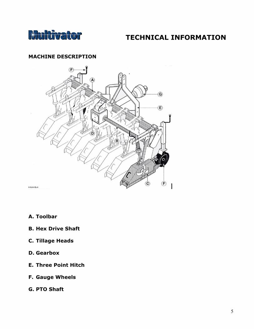
TECHNICAL INFORMATION MACHINE DESCRIPTION
A. Toolbar
B. Hex Drive Shaft
C. Tillage Heads
D. Gearbox
E. Three Point Hitch
F. Gauge Wheels
G. PTO Shaft
5

TECHNICAL INFORMATION
MACHINE DESCRIPTION Steering Guide
Ridger Assembly
6
TECHNICAL INFORMATION
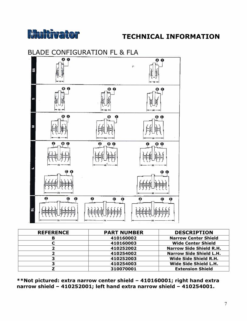
BLADE CONFIGURATION FL & FLA
REFERENCE PART NUMBER DESCRIPTION B 410160002 Narrow Center Shield C 410160003 Wide Center Shield 2 410252002 Narrow Side Shield R.H. 2 410254002 Narrow Side Shield L.H. 3 410252003 Wide Side Shield R.H. 3 410254003 Wide Side Shield L.H. Z 310070001 Extension Shield
**Not pictured: extra narrow center shield – 410160001; right hand extra narrow shield – 410252001; left hand extra narrow shield – 410254001.
7
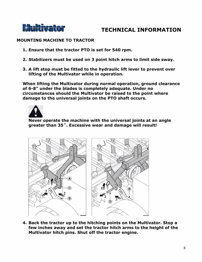
TECHNICAL INFORMATION MOUNTING MACHINE TO TRACTOR
1. Ensure that the tractor PTO is set for 540 rpm. 2. Stabilizers must be used on 3 point hitch arms to limit side sway.
3. A lift stop must be fitted to the hydraulic lift lever to prevent over
lifting of the Multivator while in operation.
When lifting the Multivator during normal operation, ground clearance of 6-8” under the blades is completely adequate. Under no circumstances should the Multivator be raised to the point where damage to the universal joints on the PTO shaft occurs.
Never operate the machine with the universal joints at an angle greater than 35˚. Excessive wear and damage will result!
4. Back the tractor up to the hitching points on the Multivator. Stop a few inches away and set the tractor hitch arms to the height of the Multivator hitch pins. Shut off the tractor engine.
8
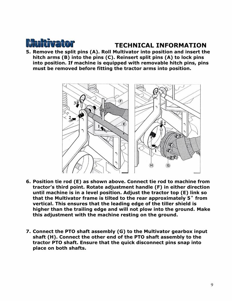
TECHNICAL INFORMATION 5. Remove the split pins (A). Roll Multivator into position and insert the
hitch arms (B) into the pins (C). Reinsert split pins (A) to lock pins into position. If machine is equipped with removable hitch pins, pins must be removed before fitting the tractor arms into position.
6. Position tie rod (E) as shown above. Connect tie rod to machine from tractor’s third point. Rotate adjustment handle (F) in either direction until machine is in a level position. Adjust the tractor top (E) link so that the Multivator frame is tilted to the rear approximately 5˚ from vertical. This ensures that the leading edge of the tiller shield is higher than the trailing edge and will not plow into the ground. Make this adjustment with the machine resting on the ground.
7. Connect the PTO shaft assembly (G) to the Multivator gearbox input shaft (H). Connect the other end of the PTO shaft assembly to the tractor PTO shaft. Ensure that the quick disconnect pins snap into place on both shafts.
9
At this point you may have determined that the PTO shaft assembly needs to be shortened. If you can connect the PTO shaft to the tractor and Multivator without shortening it, you must ensure that the PTO shaft will not bottom out during operation. This may occur when raising or lowering the Multivator. If the shaft bottoms out during operation damage may occur to the PTO shaft assembly, Multivator gearbox and the tractor PTO.
TECHNICAL INFORMATION Following are 2 techniques for measuring for the correct length of PTO shaft:
a. With the Multivator attached to the tractor, measure the horizontal distance from the input shaft on the gearbox to the tractor PTO shaft. Place the fully closed PTO shaft assembly on the ground and measure its overall length. If the PTO shaft assembly is shorter than the distance between the tractor PTO shaft and gearbox then you should not have to shorten it. If it is longer, then subtract the shorter measurement from the longer measurement. Add 1” to the difference. The result is the excess length that will need to be removed from each half of the PTO shaft assembly.
b. With the Multivator attached to the tractor, separate the PTO shaft
assembly into two halves and attach one half to the tractor and one half to the Multivator. Hold each half alongside each other and determine the excess length of each half of the PTO shaft assembly.
PROCEDURE FOR CUTTING THE PTO SHAFT: a. Separate the PTO shaft into two halves. b. Using the measurement obtained above, shorten the plastic guarding
using a hack saw. c. Using a chop saw, or a hack saw, shorten the steel profile tube by the
same amount. d. Cut each half of the PTO shaft. e. De-burr the profile tubes. f. Grease and reassemble the PTO shaft.
10
OPERATION
PRE-WORK INSPECTION Before using your Multivator, perform the following checks and services each day. (See Maintenance section for further details.)
1. Check gearbox for sufficient oil. If oil is to be added, use SAE 140 EP gear oil.
2. Grease the PTO shaft sliding sections and universal joints. 3. Grease the gauge wheel axles. 4. Remove any trash or material wrapped around the rotor or the
rotor bearing covers. 5. Check for loose blades. Tighten any blade bolts as necessary.
Loose blade bolts can lead to broken blades. 6. Check all bolts on machine for tightness.
SETTING DEPTH Cultivation depth is controlled by raising or lowering the gauge wheels on the front of the tool bar. With the Multivator attached to the tractor, and with the blades resting on the ground, raise the gauge wheels to the desired cultivation depth. Typically, this will be between 1” and 4” deep. WORKING Start the tractor engine and lift the Multivator clear of the ground. Six to eight inches should be sufficient height to lift the machine. Proceed to the work site and position the tractor for the first run. Engage the tractor PTO, select a low gear, and move ahead slowly lowering the Multivator into the ground. Use at least ¾ throttle when starting and increase to rated engine speed at 540 PTO rpm as the Multivator sets into the soil. The Flow Rate Control Knob for the tractor hydraulics may need to be set to the “Slow” position to ensure gentle lowering of the machine into the gound. Also make sure that the three point hitch is set in the “Float” position.
11
OPERATION
After a short working distance, stop the tractor and check your work to see that desired results are being obtained. RUNNING IN For the first 10 hours of operation, run the Multivator easily. Do not allow the Multivator to lug the tractor down. Check the temperature of the gearbox and chaincase units to ensure that they are not operating at excessive heat levels. High temperatures can be an indication of a potential problem with a component, low oil levels, or possibly an assembly problem. GROUND SPEED Ground speed is governed by power and soil conditions. Hard ground will require lower travel speeds to maintain smooth operation. Good ground conditions with reasonable moisture will allow speeds of 4-5 mph. Light ground conditions, shallow cultivation, or a second pass will allow travel speeds of 5-6 mph. ENGINE RPM Try to operate at the rated engine speed to achieve 540 RPM PTO speed. Allowing the tractor to lug down continuously can result in damage to the tractor and the Multivator. SOIL TILTH CONTROL Tilth is governed by forward speed and engine RPM. Slower forward speeds will give the finest possible finish. Higher forward speeds will give a cloddier or rougher finish.
12
OPERATION
HEADLAND PROCEDURE Each time the headland is reached, lift the machine clear of the ground (6” to 8” maximum). With the blades rotating, turn the tractor for the next pass, and slowly lower the machine into the ground. DO NOT TURN THE TRACTOR WITH THE MULTIVATOR IN THE GROUND! WORKING LIMITATIONS It is very important that the Multivator be used in conditions that will not obviously damage the machine. The Multivator has the ability to handle small stones and other obstacles by “walking over” these obstacles and kicking them out behind the machine. The forward rotating blades, and free floating heads, allow for this action to occur. Extremely rugged conditions will cause excessive wear and tear on blades, shielding, and working components of the machine, requiring more operator maintenance. If the blades do not penetrate the soil easily, and you can not obtain more than 1” depth on a first pass with wheels clear of the ground, conditions may be too dry and hard. Continued use of the Multivator in such conditions will cause excessive wear on the drive train and will void any warranty consideration. If considerable vibration, jumping, and shock loading is apparent, then the conditions are not suitable to work in. If these conditions are unavoidable, then please adhere to the following guidelines:
• Try to irrigate, or wait until adequate soil moisture is present • Use another tillage tool, such as a chisel shank or V-ripper, to relieve
compaction before using the Multivator • Relieve spring tension on the tiller heads to allow them to float more
easily over obstacles • Fit a safety clutch to the PTO drive line • Increase the frequency of machine inspections during operation
13
OPERATION
• Be attentive to the machine and any potential problems, particularly loose blade bolts, broken blades, and high fluid temperatures in the gearbox and chaincases
ABRASIVE SOILS Use in very abrasive soils will significantly reduce blade life. These soils are sandy or gravelly in nature. Additional care should be taken to inspect the chaincase skid at regular intervals. The chaincase skid provides important protection to the chaincase, as well as eliminating the center untilled strip. The chaincase skid must be replaced when it is worn out. Optional chaincase wearing shoes are available from the manufacturer. These wearing shoes bolt to the underside of the chaincase and provide an additional wearing surface. They may provide additional protection in very abrasive conditions. HEAVY TRASH CONDITIONS In very tall weed growth, tough grass tilling, corn residue, stalky or vine type weeds, care should be taken to avoid excessive weed wrap on the blades and rotors. After using the Multivator, clean any residue from the tilling blades, particularly between the inner blade flanges and the chaincase. If trash buildup is occurring on the shields, reposition the shields so they are angled down in the back and up in the front. This is accomplished by repositioning the brackets to which the shields are mounted. If trash buildup is occurring on the center sweep, it may be necessary to remove the “wings” from the center sweep with a torch. The center sweep will then slice through the soil and trash. However, it should be remembered that removing the wings from the center sweep will reduce the effectiveness of the sweep for weed removal.
14
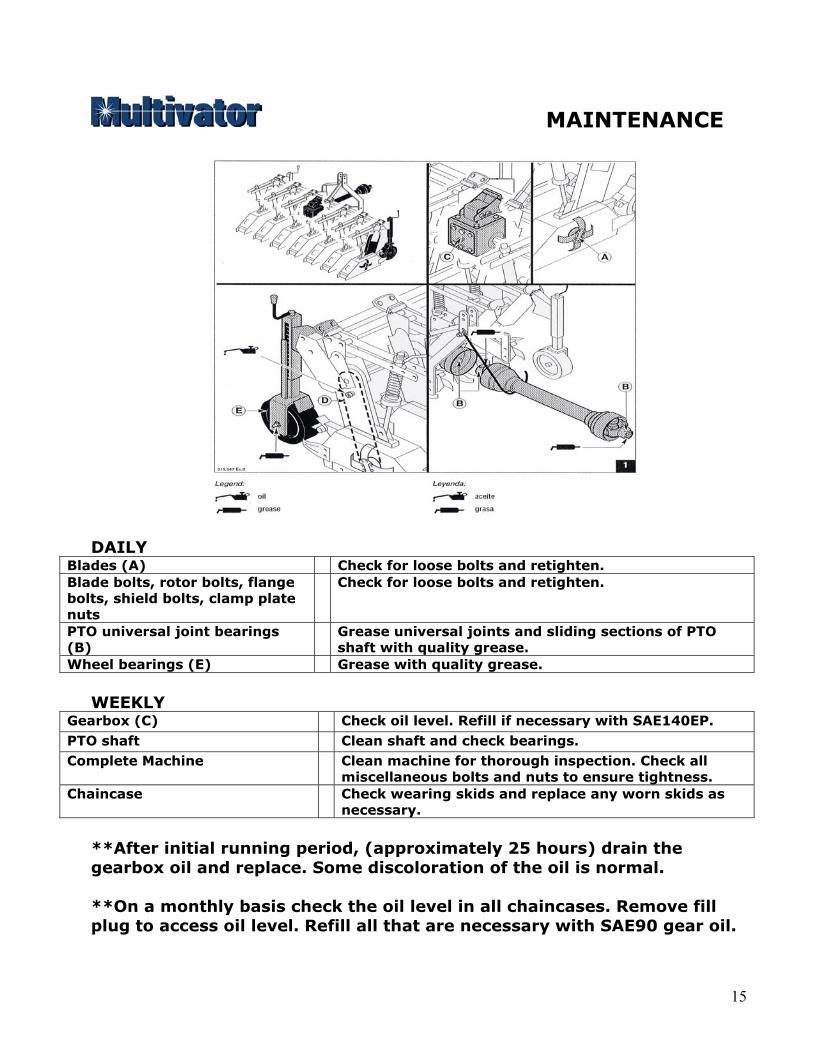
MAINTENANCE
DAILY
Blades (A) Check for loose bolts and retighten. Blade bolts, rotor bolts, flange bolts, shield bolts, clamp plate nuts
Check for loose bolts and retighten.
PTO universal joint bearings (B)
Grease universal joints and sliding sections of PTO shaft with quality grease.
Wheel bearings (E) Grease with quality grease. WEEKLY
Gearbox (C) Check oil level. Refill if necessary with SAE140EP. PTO shaft Clean shaft and check bearings. Complete Machine Clean machine for thorough inspection. Check all
miscellaneous bolts and nuts to ensure tightness. Chaincase Check wearing skids and replace any worn skids as
necessary. **After initial running period, (approximately 25 hours) drain the gearbox oil and replace. Some discoloration of the oil is normal. **On a monthly basis check the oil level in all chaincases. Remove fill plug to access oil level. Refill all that are necessary with SAE90 gear oil.
15
MAINTENANCE CHAIN ADJUSTMENT On models FL and FLA an automatic chain tensioner is supplied which eliminates the need for manual chain adjustement. CHAINCASE LUBRICATION Each chaincase is supplied fully lubricated. Over time, lubricant will need to be replaced, and periodically the chaincase may need to be completely flushed and refilled. Adding lubricant is done through the breather – fill plug located on the side of the chaincase. Chaincases should be filled approximately 1/3 full with good quality SAE90 gear oil. If too much oil is added to the chaincase you will notice oil escaping from the breather plug in a fine mist. Another method of lubricating the chaincase is to pack the case completely with grease. This can be done when renovating old chaincases with worn components, as the grease helps to seal the chaincase from dirt. ROTOR MAINTENANCE Remove flanges and draw bolt(s) on a yearly basis, preferably before the initial use for the season. Remove all foreign debris that has accumulated on flanges, blades, rotor, and dust covers. Inspect all flanges, draw bolts, metal dust covers, and oil seals. Replace any and all items with excessive wear. Be sure that oil seals are intact and not leaking chaincase oil.
16

TROUBLESHOOTING
PROBLEM DIAGNOSIS
PTO shaft vibrates or chatters Check for worn cross and bearing kits. Pay attention to lift height when machine is in use. Lifting machine too high puts the PTO at angles causing premature wear.
Gearbox noise is noticeable or constant.
Check oil level in gearbox. Make sure nothing is obstructing moving components tied to gearbox.
Intermittent clicking noise from rotors, chaincase or gearbox.
Check for loose blades. If noise persists check gearbox for damage to pinion gear or ring gear teeth. Clicking noises inside chaincase can indicate a worn chain skid. Replace as necessary.
Slapping noise from chaincase Chain is too loose. If chain is worn it should be replaced or shortened if possible.
Hex drive shaft is rotating but blades are not.
This indicates a broken chain link inside the chaincase, broken or rounded off drawbolt.
Burning smell, or signs of excessive heat.
Usually caused by rotors which are not turning freely. Check for trash wrapped around rotor, especially between inner rotor and dust cover.
Blades won’t penetrate average soil conditions
Check that blades are installed correctly. Blades or complete flange may have been installed backwards
Machine skips or does not cut all weed residue.
Check for worn blades. If blades are worn down to a sharp point, overlap will be lost and cutting ability will deteriorate. Replace worn blades
Machine vibrates while tilling Check for bent flanges or a bent draw bolt.
17
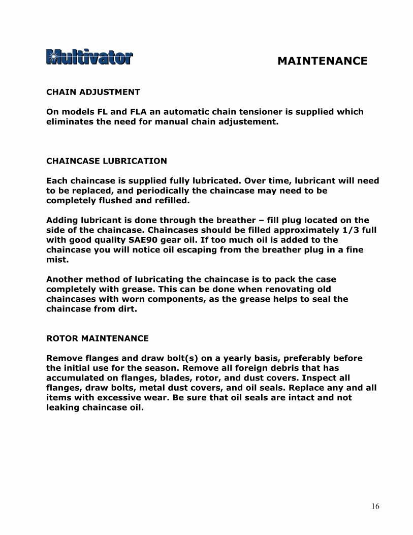
No. Part Number Qty. Description
1 420610061 1 Top tube2 103040072 8 M16 Locknut3 350770012 4 Clamp plate4 103120007 2 Plastic plug5 410610084 2 Side support6 410610075 2 Center support7 101070002 2 Clip pin8 103150128 8 Bolt M16x559 310560015 2 Hitch pin Cat I10 103150109 1 Bolt M14x10011 103040070 2 Locknut M1412 103040022 8 Nut M1213 310770002 4 Clamp plate14 410680016 1 Link arm15 103150098 1 Bolt M14x35
Not Illustrated420610074 1 Top tube - short
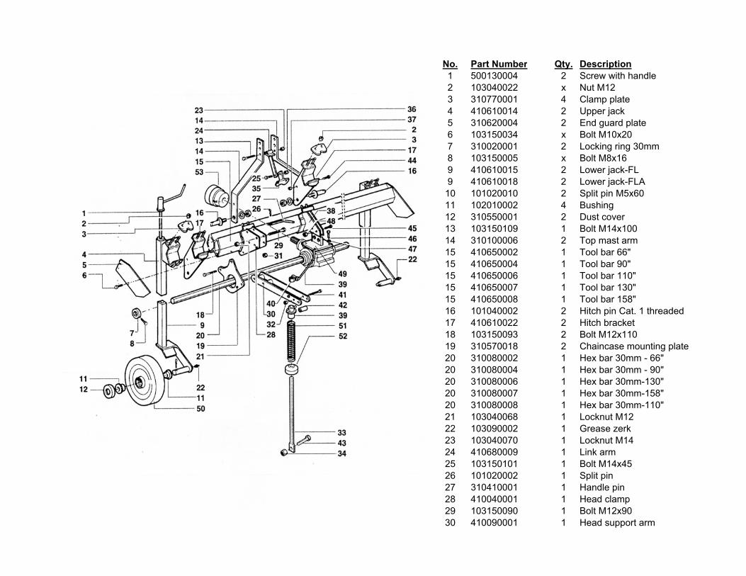
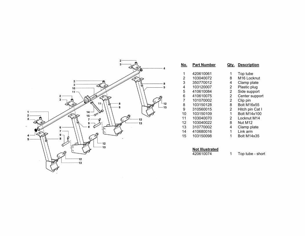
No. Part Number Qty. Description1 500130004 2 Screw with handle2 103040022 x Nut M123 310770001 4 Clamp plate4 410610014 2 Upper jack5 310620004 2 End guard plate6 103150034 x Bolt M10x207 310020001 2 Locking ring 30mm8 103150005 x Bolt M8x169 410610015 2 Lower jack-FL 9 410610018 2 Lower jack-FLA10 101020010 2 Split pin M5x6011 102010002 4 Bushing12 310550001 2 Dust cover13 103150109 1 Bolt M14x10014 310100006 2 Top mast arm15 410650002 1 Tool bar 66"15 410650004 1 Tool bar 90"15 410650006 1 Tool bar 110"15 410650007 1 Tool bar 130"15 410650008 1 Tool bar 158"16 101040002 2 Hitch pin Cat. 1 threaded17 410610022 2 Hitch bracket18 103150093 2 Bolt M12x11019 310570018 2 Chaincase mounting plate20 310080002 1 Hex bar 30mm - 66"20 310080004 1 Hex bar 30mm - 90"20 310080006 1 Hex bar 30mm-130"20 310080007 1 Hex bar 30mm-158"20 310080008 1 Hex bar 30mm-110"21 103040068 1 Locknut M1222 103090002 1 Grease zerk23 103040070 1 Locknut M1424 410680009 1 Link arm25 103150101 1 Bolt M14x4526 101020002 1 Split pin 27 310410001 1 Handle pin28 410040001 1 Head clamp29 103150090 1 Bolt M12x9030 410090001 1 Head support arm
No. Part Number Qty. Description
31 103040022 2 M12 Nut32 103040008 1 M8 Nut33 310820002 1 Threaded rod FL 33 310820002 1 Threaded rod FLA34 103040064 1 M8 Locknut35 410600001 1 T-clamp plate36 103040070 1 M14 Locknut37 103040070 2 M14 Locknut38 410610021 1 Upper gearbox mounting plate39 410490001 1 Spring guide40 510130001 1 Handle with nut41 103150029 1 Bolt M8x7042 310210009 1 Spacer43 103150011 1 Bolt M8x2544 103150101 2 Bolt M14x4545 103150081 2 Bolt M12x6046 103150044 4 Bolt M10x3047 103100008 4 Washer M1048 103040068 2 M12 Locknut49 410610057 1 Lower gearbox mounting plate50 101050010 1 Wheel51 310470001 1 Spring 52 410120001 1 Collar53 101010002 1 PTO guard
Not Illustrated310560002 2 Wheel axle
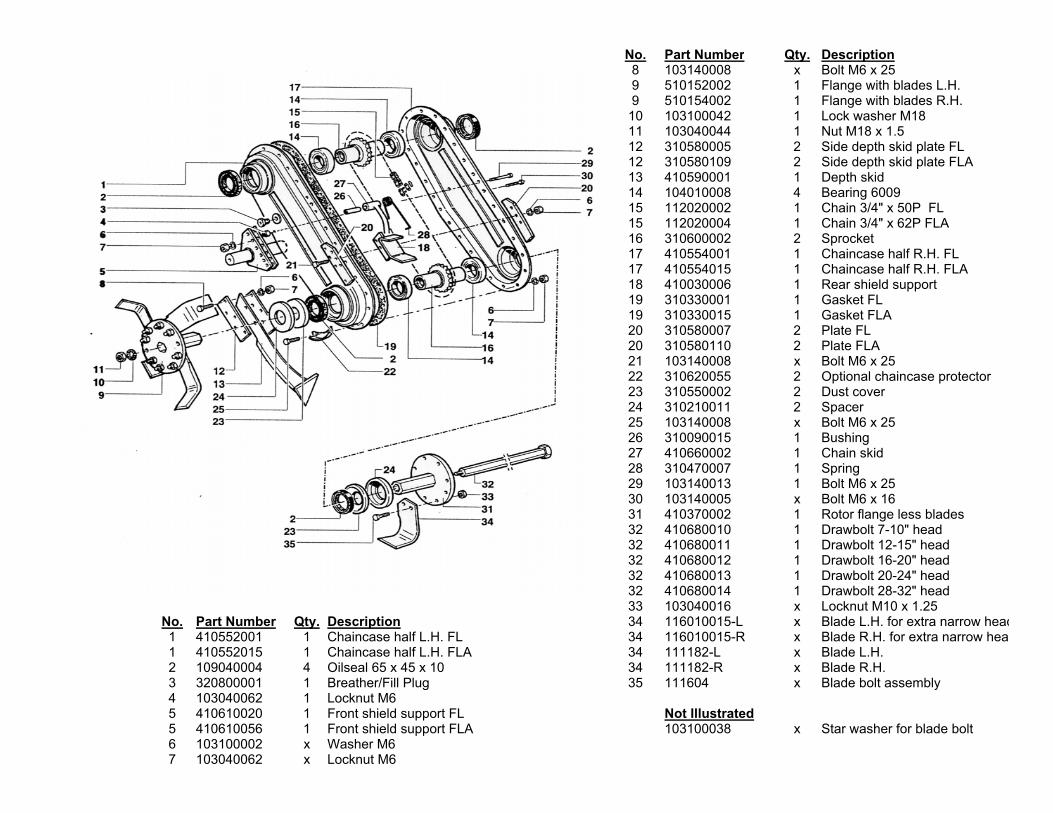
No. Part Number Qty. Description8 103140008 x Bolt M6 x 259 510152002 1 Flange with blades L.H.9 510154002 1 Flange with blades R.H.10 103100042 1 Lock washer M1811 103040044 1 Nut M18 x 1.512 310580005 2 Side depth skid plate FL12 310580109 2 Side depth skid plate FLA13 410590001 1 Depth skid14 104010008 4 Bearing 600915 112020002 1 Chain 3/4" x 50P FL15 112020004 1 Chain 3/4" x 62P FLA16 310600002 2 Sprocket17 410554001 1 Chaincase half R.H. FL17 410554015 1 Chaincase half R.H. FLA18 410030006 1 Rear shield support19 310330001 1 Gasket FL19 310330015 1 Gasket FLA20 310580007 2 Plate FL 20 310580110 2 Plate FLA21 103140008 x Bolt M6 x 2522 310620055 2 Optional chaincase protector23 310550002 2 Dust cover24 310210011 2 Spacer25 103140008 x Bolt M6 x 2526 310090015 1 Bushing27 410660002 1 Chain skid28 310470007 1 Spring29 103140013 1 Bolt M6 x 2530 103140005 x Bolt M6 x 1631 410370002 1 Rotor flange less blades32 410680010 1 Drawbolt 7-10" head32 410680011 1 Drawbolt 12-15" head32 410680012 1 Drawbolt 16-20" head32 410680013 1 Drawbolt 20-24" head32 410680014 1 Drawbolt 28-32" head33 103040016 x Locknut M10 x 1.25
No. Part Number Qty. Description 34 116010015-L x Blade L.H. for extra narrow head1 410552001 1 Chaincase half L.H. FL 34 116010015-R x Blade R.H. for extra narrow hea1 410552015 1 Chaincase half L.H. FLA 34 111182-L x Blade L.H.2 109040004 4 Oilseal 65 x 45 x 10 34 111182-R x Blade R.H.3 320800001 1 Breather/Fill Plug 35 111604 x Blade bolt assembly4 103040062 1 Locknut M65 410610020 1 Front shield support FL Not Illustrated5 410610056 1 Front shield support FLA 103100038 x Star washer for blade bolt6 103100002 x Washer M67 103040062 x Locknut M6
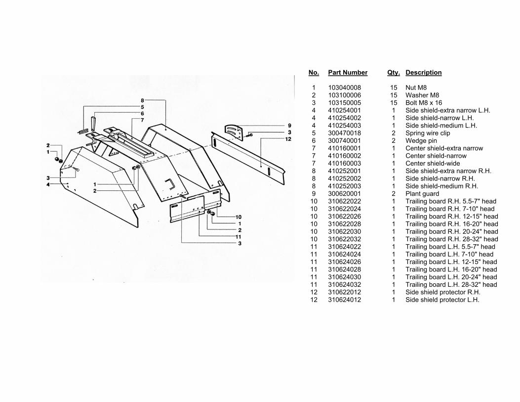
No. Part Number Qty. Description
1 103040008 15 Nut M82 103100006 15 Washer M83 103150005 15 Bolt M8 x 164 410254001 1 Side shield-extra narrow L.H.4 410254002 1 Side shield-narrow L.H.4 410254003 1 Side shield-medium L.H.5 300470018 2 Spring wire clip6 300740001 2 Wedge pin7 410160001 1 Center shield-extra narrow7 410160002 1 Center shield-narrow7 410160003 1 Center shield-wide8 410252001 1 Side shield-extra narrow R.H.8 410252002 1 Side shield-narrow R.H.8 410252003 1 Side shield-medium R.H.9 300620001 2 Plant guard10 310622022 1 Trailing board R.H. 5.5-7" head10 310622024 1 Trailing board R.H. 7-10" head10 310622026 1 Trailing board R.H. 12-15" head10 310622028 1 Trailing board R.H. 16-20" head10 310622030 1 Trailing board R.H. 20-24" head10 310622032 1 Trailing board R.H. 28-32" head11 310624022 1 Trailing board L.H. 5.5-7" head11 310624024 1 Trailing board L.H. 7-10" head11 310624026 1 Trailing board L.H. 12-15" head11 310624028 1 Trailing board L.H. 16-20" head11 310624030 1 Trailing board L.H. 20-24" head11 310624032 1 Trailing board L.H. 28-32" head12 310622012 1 Side shield protector R.H.12 310624012 1 Side shield protector L.H.
No. Part Number Qty. Description
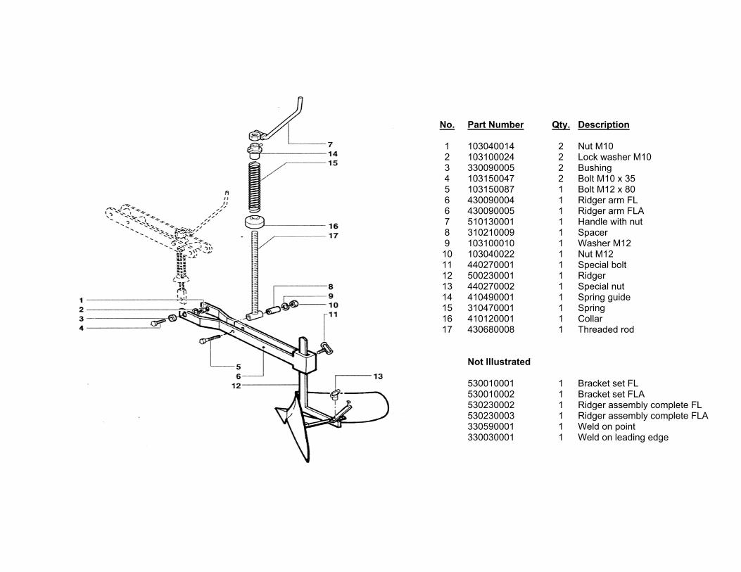
1 103040014 2 Nut M102 103100024 2 Lock washer M103 330090005 2 Bushing4 103150047 2 Bolt M10 x 355 103150087 1 Bolt M12 x 806 430090004 1 Ridger arm FL6 430090005 1 Ridger arm FLA7 510130001 1 Handle with nut8 310210009 1 Spacer9 103100010 1 Washer M1210 103040022 1 Nut M1211 440270001 1 Special bolt12 500230001 1 Ridger13 440270002 1 Special nut14 410490001 1 Spring guide15 310470001 1 Spring 16 410120001 1 Collar17 430680008 1 Threaded rod
Not Illustrated
530010001 1 Bracket set FL530010002 1 Bracket set FLA530230002 1 Ridger assembly complete FL530230003 1 Ridger assembly complete FLA330590001 1 Weld on point330030001 1 Weld on leading edge
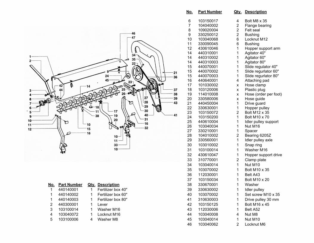
No. Part Number Qty. Description
6 103150017 4 Bolt M8 x 357 104040002 2 Flange bearing8 109020004 2 Felt seal9 330250012 2 Bushing10 103040068 6 Locknut M1211 330090045 6 Bushing12 430610046 1 Hopper support arm14 440310001 1 Agitator 40"14 440310002 1 Agitator 60"14 440310003 1 Agitator 80"15 440070001 1 Slide regulator 40"15 440070002 1 Slide regurlator 60"15 440070003 1 Slide regurlator 80"16 440640001 4 Attaching pad17 101030002 x Hose clamp18 103120006 x Plastic plug19 114010008 x Hose (order per foot)20 330580006 x Hose guide21 440450004 1 Drive guard22 330630001 1 Hopper pulley23 103150072 2 Bolt M12 x 3524 103150200 1 Bolt M10 x 7025 440610004 1 Idler pulley support26 103040034 1 Nut M1627 330210001 1 Spacer28 104010002 2 Bearing 6205Z29 330560001 1 Idler pulley axle30 103010002 1 Snap ring31 103100014 1 Washer M1632 430610047 1 Hopper support drive33 310770001 2 Clamp plate34 103040014 1 Nut M1035 103070002 1 Bolt M10 x 3536 112030001 1 Belt A4337 103150034 1 Bolt M10 x 20
No. Part Number Qty. Description 38 330670001 1 Washer 1 440140001 1 Fertilizer box 40" 39 330630002 1 Idler pulley1 440140002 1 Fertilizer box 60" 40 103070002 1 Set screw M10 x 351 440140003 1 Fertilizer box 80" 41 310630003 1 Drive pulley 30 mm2 440300001 1 Lever 42 103150125 1 Bolt M16 x 453 103100014 1 Washer M16 43 112030006 1 Belt A524 103040072 1 Locknut M16 44 103040008 4 Nut M85 103100006 4 Washer M8 45 103040014 1 Nut M10
46 103040062 2 Locknut M6
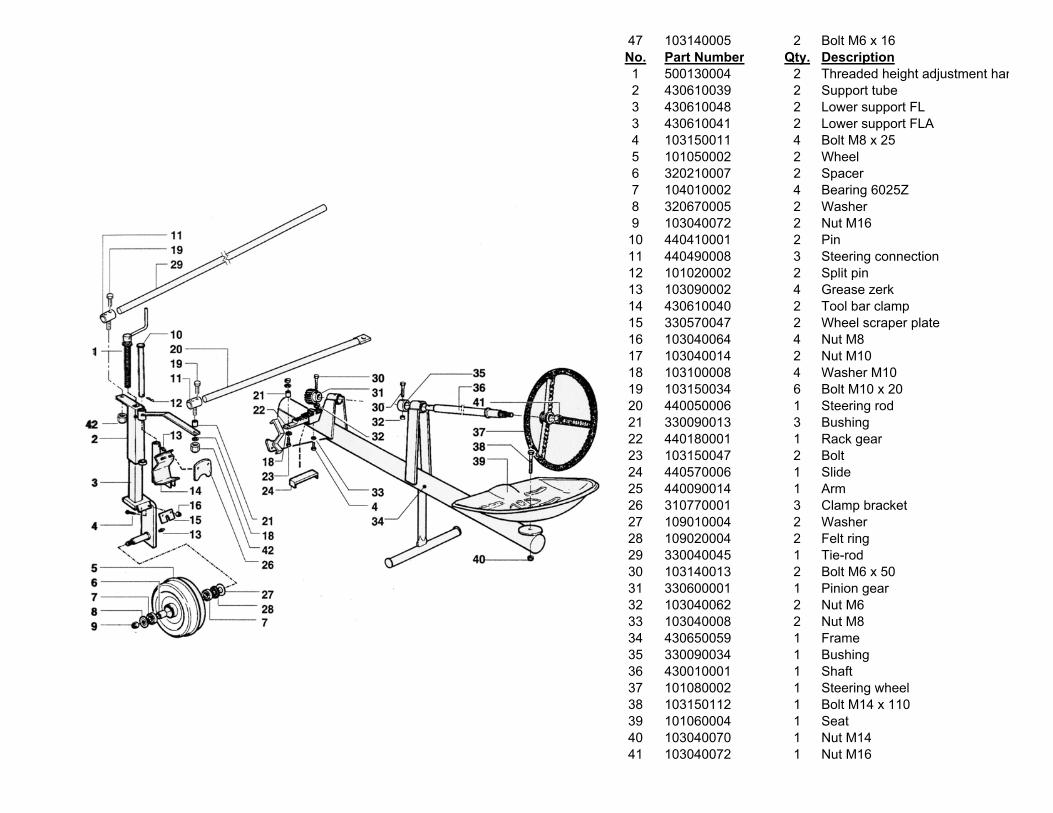
47 103140005 2 Bolt M6 x 16 No. Part Number Qty. Description1 500130004 2 Threaded height adjustment han2 430610039 2 Support tube3 430610048 2 Lower support FL3 430610041 2 Lower support FLA4 103150011 4 Bolt M8 x 255 101050002 2 Wheel6 320210007 2 Spacer7 104010002 4 Bearing 6025Z8 320670005 2 Washer9 103040072 2 Nut M1610 440410001 2 Pin11 440490008 3 Steering connection12 101020002 2 Split pin13 103090002 4 Grease zerk14 430610040 2 Tool bar clamp15 330570047 2 Wheel scraper plate16 103040064 4 Nut M817 103040014 2 Nut M1018 103100008 4 Washer M1019 103150034 6 Bolt M10 x 2020 440050006 1 Steering rod21 330090013 3 Bushing22 440180001 1 Rack gear23 103150047 2 Bolt24 440570006 1 Slide25 440090014 1 Arm26 310770001 3 Clamp bracket27 109010004 2 Washer28 109020004 2 Felt ring29 330040045 1 Tie-rod30 103140013 2 Bolt M6 x 5031 330600001 1 Pinion gear32 103040062 2 Nut M633 103040008 2 Nut M834 430650059 1 Frame35 330090034 1 Bushing36 430010001 1 Shaft37 101080002 1 Steering wheel38 103150112 1 Bolt M14 x 11039 101060004 1 Seat40 103040070 1 Nut M1441 103040072 1 Nut M16
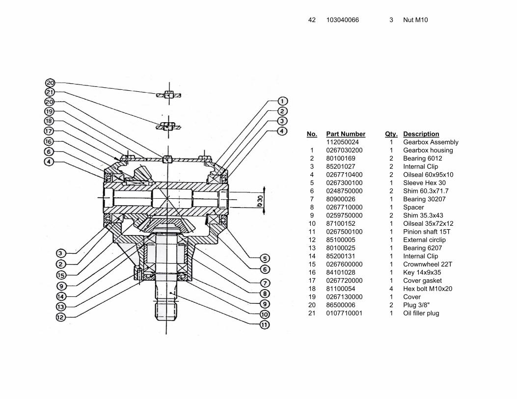
42 103040066 3 Nut M10
No. Part Number Qty. Description112050024 1 Gearbox Assembly
1 0267030200 1 Gearbox housing2 80100169 2 Bearing 60123 85201027 2 Internal Clip4 0267710400 2 Oilseal 60x95x105 0267300100 1 Sleeve Hex 306 0248750000 2 Shim 60.3x71.77 80900026 1 Bearing 302078 0267710000 1 Spacer9 0259750000 2 Shim 35.3x4310 87100152 1 Oilseal 35x72x1211 0267500100 1 Pinion shaft 15T12 85100005 1 External circlip13 80100025 1 Bearing 620714 85200131 1 Internal Clip15 0267600000 1 Crownwheel 22T16 84101028 1 Key 14x9x3517 0267720000 1 Cover gasket18 81100054 4 Hex bolt M10x2019 0267130000 1 Cover 20 86500006 2 Plug 3/8"21 0107710001 1 Oil filler plug
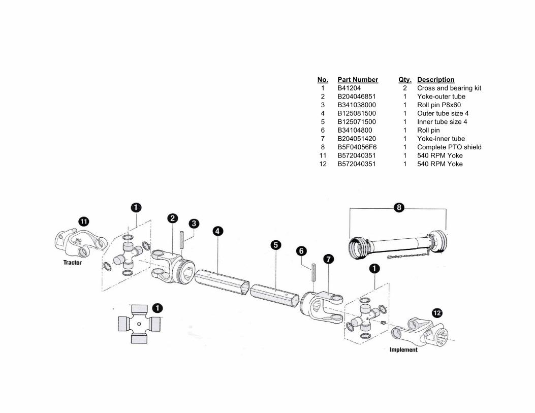
No. Part Number Qty. Description1 B41204 2 Cross and bearing kit2 B204046851 1 Yoke-outer tube3 B341038000 1 Roll pin P8x604 B125081500 1 Outer tube size 4
5 B125071500 1 Inner tube size 46 B34104800 1 Roll pin 7 B204051420 1 Yoke-inner tube8 B5F04056F6 1 Complete PTO shield11 B572040351 1 540 RPM Yoke12 B572040351 1 540 RPM Yoke
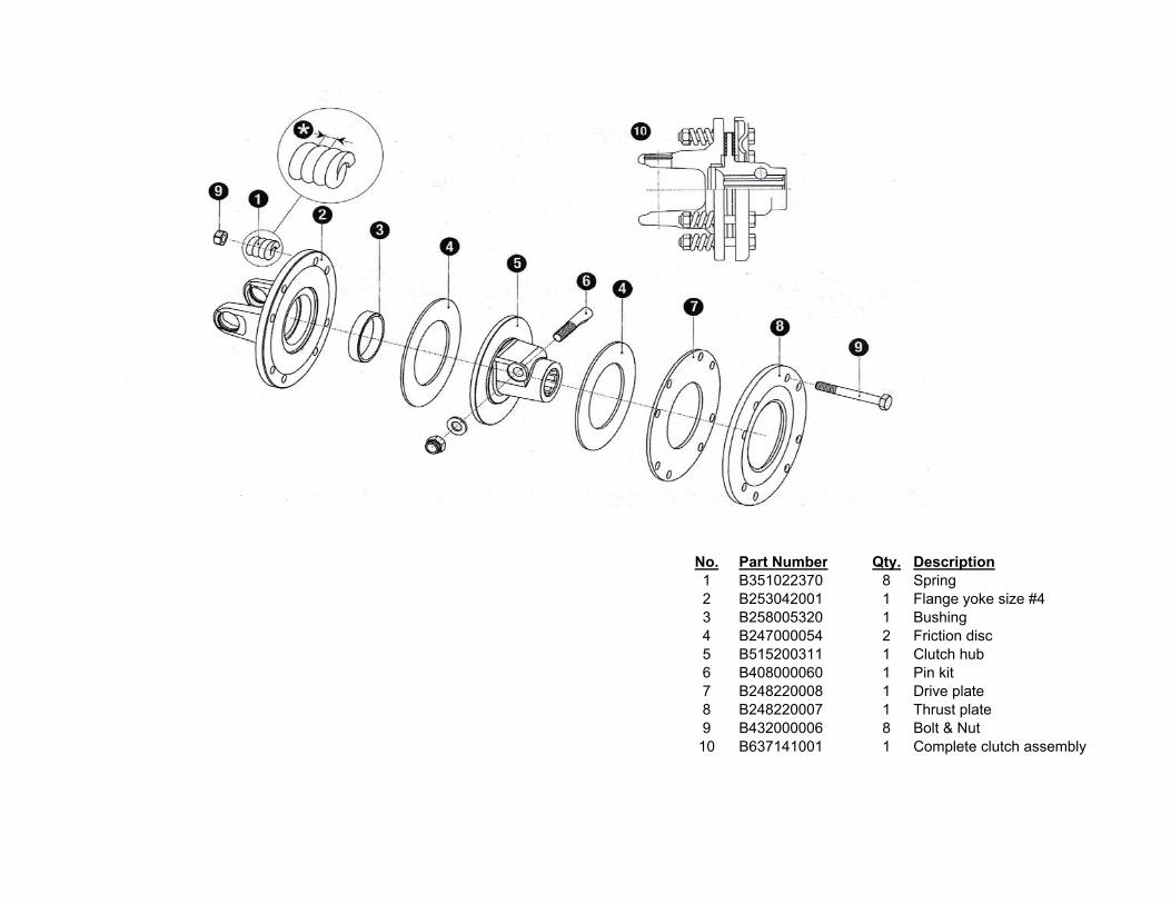
No. Part Number Qty. Description1 B351022370 8 Spring2 B253042001 1 Flange yoke size #43 B258005320 1 Bushing4 B247000054 2 Friction disc5 B515200311 1 Clutch hub6 B408000060 1 Pin kit7 B248220008 1 Drive plate8 B248220007 1 Thrust plate9 B432000006 8 Bolt & Nut10 B637141001 1 Complete clutch assembly