ROUND BALE WRAPPER Spin S Spin F - jawas.home.pljawas.home.pl/samasz/instrukcje/IN129USA.pdf ·...
39
SaMASZ Sp. z o.o. Poland, 16-060 Zabludów, ul. Trawiasta 1 Established – 1984 NIP PL-966-159-29-76 tel. (+48) (85) 664 70 31 fax (+48) (85) 664 70 41 e-mail: [email protected] www.samasz.pl OPERATOR'S MANUAL ROUND BALE WRAPPER Spin S Spin F IN129USA001 2014.12.16 Edition 1 The original instruction Serial no.:
Transcript of ROUND BALE WRAPPER Spin S Spin F - jawas.home.pljawas.home.pl/samasz/instrukcje/IN129USA.pdf ·...

SaMASZ Sp. z o.o. Poland, 16-060 Zabłudów, ul. Trawiasta 1
Established – 1984
NIP PL-966-159-29-76
tel. (+48) (85) 664 70 31 fax (+48) (85) 664 70 41
e-mail: [email protected] www.samasz.pl
OPERATOR'S MANUAL
ROUND BALE WRAPPER
Spin S Spin F
IN129USA001 2014.12.16
Edition 1
The original instruction
Serial no.:
NOTE:
Always turn off the engine and remove the ignition key before entering or servicing the
machine, lifting side guards, setting rotor sensors or discharging unwrapped bales. It is
forbidden to mount the machine during operation.
NOTE: Operating bale wrapper without previous
familiarizing with its contents as well as by unauthorized personnel, particularly by
children, is strictly forbidden.
NOTE: The operator is responsible for fitting and
maintenance of road lights as well as labeling the machine in compliance with traffic rules
and regulations.
NOTE: Keep this manual for future use.

Operator's Manual
Round bale wrapper Spin S, Spin F
- 1 -
Contents page 1. IDENTIFYING THE MACHINE ........................................................................................... 2 2. INTRODUCTION .................................................................................................................... 3 3. TECHNICAL DESCRIPTION ..................................................................................................... 4
3.1. Technical data ..................................................................................................................................... 4 3.2. Wrapping machine construction ......................................................................................................... 5 3.3. Intended use ........................................................................................................................................ 6 3.4. Standard equipment and spare parts .................................................................................................... 6
4. SAFETY PRECAUTIONS ............................................................................................................ 7 4.2. Hazards ............................................................................................................................................... 8 4.3. Bale loading ........................................................................................................................................ 8 4.4. Driving on public roads ...................................................................................................................... 9 4.5. Warning signs and their meanings .................................................................................................... 10
5. DRIVE OPERATION .................................................................................................................. 14 5.1. Drive coupling ................................................................................................................................... 14 5.2. Disconnecting the drive ..................................................................................................................... 15
6. COMMISSIONING ..................................................................................................................... 16 6.1. Commissioning of the counter ........................................................................................................... 16
7. CONTROLS AND ONGOING ADJUSTMENTS ............................................................... 17 7.1. Location of the controls .................................................................................................................... 17 7.2. Location of ongoing adjustment points ............................................................................................. 18
8. WRAPPING MACHINE OPERATION .............................................................................. 20 8.1. Installing the film .............................................................................................................................. 20 8.2. Hydraulic system .............................................................................................................................. 21 8.3. Wrap counter ..................................................................................................................................... 22 8.4. Wrapping .......................................................................................................................................... 24 8.5. Unloading the wrapped bale ............................................................................................................. 27 8.6. Drive chain adjustment ..................................................................................................................... 30 8.7. Finishing work .................................................................................................................................. 31
9. REGULAR INSPECTION ..................................................................................................... 32 9.1. User inspection ................................................................................................................................. 32 9.2. Service checks ................................................................................................................................... 32
10. AUTHORISED SERVICE ..................................................................................................... 33 10.1. Warranty service ........................................................................................................................... 33 10.2. Ongoing maintenance ................................................................................................................... 33 10.3. Ordering replacement parts .......................................................................................................... 33
11. WRAPPING MACHINE STORAGE ................................................................................... 34 12. PROBLEMS AND THEIR REMEDIES.................................................................................. 34 13. DISASSEMBLY AND WITHDRAWAL FROM USE................ ........................................ 35 14. WARRANTY CARD .............................................................................................................. 35 15. WARRANTY CONDITIONS ................................................................................................... 36
15.1. Warranty claims procedures ............................................................................................................ 36 15.2. Record of warranty repairs ........................................................................................................... 37
Operator's Manual
Round bale wrapper Spin S, Spin F
- 2 -
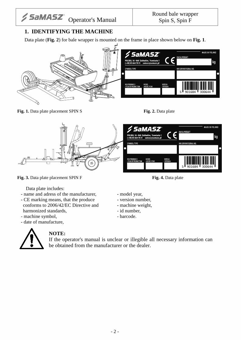
1. IDENTIFYING THE MACHINE Data plate (Fig. 2) for bale wrapper is mounted on the frame in place shown below on Fig. 1.
Fig. 1. Data plate placement SPIN S Fig. 2. Data plate Fig. 3. Data plate placement SPIN F Fig. 4. Data plate
Data plate includes: - name and adress of the manufacturer, - model year, - CE marking means, that the produce - version number, conforms to 2006/42/EC Directive and - machine weight, harmonized standards, - id number,
- machine symbol, - barcode. - date of manufacture,
NOTE: If the operator's manual is unclear or illegible all necessary information can be obtained from the manufacturer or the dealer.
Operator's Manual
Round bale wrapper Spin S, Spin F
- 3 -
2. INTRODUCTION General information
� Prior to operating the machine its user must familiarize himself with this manual as well as common work safety rules.
� The machine is manufactured in compliance with European safety standards. � Respecting recommendations herein shall ensure full operation safety. � If you have any questions concerning commission and operation of the machine, please
contact the manufacturer. � Operator's manual remains an integral part of the machine's equipment. � Never overload the machine. If there are any doubts regarding safety issues, please stop
working immediately and consult to a dealer. � If the machine is sold to another user, it must be supplied with the operating manual. It is
advised that the supplier has a confirmation stating that the manual was transferred together with the machine, signed by the buyer and archived.
GENERAL PRECAUTION
When operating the machine, warnings and safety rules marked with this sign herein should be respected.

Operator's Manual
Round bale wrapper Spin S, Spin F
- 4 -
3. TECHNICAL DESCRIPTION
3.1. Technical data
Tab. 1. Technical data
Designation Unit SPIN S SPIN F Coupling with the tractor - Hitched Undercarriage type - Mono-axial Overall dimensions in the working setup Length/ Width/ Height
ft. 14' 3"/ 8' 10"-12' 4"/ 8' 19' 10"/ 9' 10"/ 8' 2"
Overall dimensions in the transport setup Length/Width/Height
ft. 14' 3"/ 8'/ 7' 9" 17' 2"/ 7' 3"/ 8' 2"
Machine weight lbs. 2.094 2.755 Maximum bale weight lbs. 1.763 1.763 Wrapped bale dimension Length Diameter
ft.
3' 11" 3' 3"- 3' 11"
Maximum working speed mph 6 Maximum transport speed mph 9
Coupling with a tractor through - Tractor's upper or lower
hitch Agricultural hitch
Tractor class - 0.9 Minimum tractor power output HP 40 Required pressure in the tractor power hydraulic system
MPa 14
Recommended tractor pump output
l/min 22
Tractor hitch load kN 4.7 1.2 Wheel track in the working setup
ft. 9' 8" -
Wheel track in the transport setup
ft. 6' 8" -
Wheel spacing ft. - 6' 7" Tyres - 10,0/80 – 12 10 PR 23x8.50x12.10 PR Tyre pressure psi 51 Drawbar hitch-ring diameter ft. 1.6" Wrapping machine drive - Hydraulic, from the tractor's power hydraulics system Rotary frame drive - Hydraulic motor Maximum rotation speed of the rotary frame
rpm 35
Bale loading method - Automatic, using a loading arm
Bale unloading method - Automatic, using a tilting
frame Discharge assembly
Film cutting - Automatic, after bale wrapping is finished Film width ft. 1' 8"; 2' 6" Number of the rotary frame (table) revolutions using film : 1' 8" 2' 5"
rpm
24 16
Bale wrapping time min ~ 2 Number of operators - 1 (tractor driver) Wrap counter - Electronic, type L-02 Electrical system voltage V 12 Machine lighting - option - Following the requirements of the traffic code

Operator's Manual
Round bale wrapper Spin S, Spin F
- 5 -
3.2. Wrapping machine construction The SPIN S wrapping machine consists of the following assemblies (Fig. 5):
Fig. 5. Wrapper design SPIN S
1. Main frame 8. Cutting assembly 2. Wrapping film feeder 9. Side taper 3. Movable frame 10. Rotary axle shaft 4. Rotary frame 11. Hydraulic control unit 5. Loading arm 12. Control levers 6. Drawbar 13. L-02 Counter 7. Support foot
The SPIN F wrapping machine consists of the following assemblies (Fig. 6):
Fig. 6. Wrapper design SPIN F
1. Complete axle with ground wheels 8. Support foot 2. Lower frame 9. Cutting unit 3. Rotary frame 10. Wheel lock wedge 4. Loading arm 11. Side wheel 5. Unloading arm 12. Hydraulic control unit 6. Drawbar 13. Control levers 7. Support foot 14. L-02 Counter
Film movement diagram
Film movement diagram
Operator's Manual
Round bale wrapper Spin S, Spin F
- 6 -
3.3. Intended use The wrapping machine shall be operated according to its intended use by coupling it with a
tractor with nominal power exceeding 40 HP and traction class of at least 0.9. The SPIN S and SPIN F bale wrapping machines are designed to pick up bales from the
ground, wrap them in film and unload to the ground. Dry grass and other papilionaceous plants with humidity of approx. 60% shall be rolled into
bales using the collecting and wrapping presses. The bale wrapping process should be conducted on the field or in the storage yard practically immediately after they have been rolled (up to 2 hours). The wrapped bales should be stacked in up to two layers on a dry level Surface making sure the wrapping film is not torn.
The fermentation process must continue for 6 to 8 weeks in positive temperatures. Thus provided silage is fit for use as a wholesome feed for animals.
NOTE: Do not use the machine for purposes other than abovementioned.
3.4. Standard equipment and spare parts The user may purchase the following optional and additional equipment a tan authorized reseller or directly from the manufacturer:
� warranty card, � operator's manual with list of spare parts, � spray paint (150 ml / 5 fl.oz.).
Optional equipment: � Road lights set.
Operator's Manual
Round bale wrapper Spin S, Spin F
- 7 -
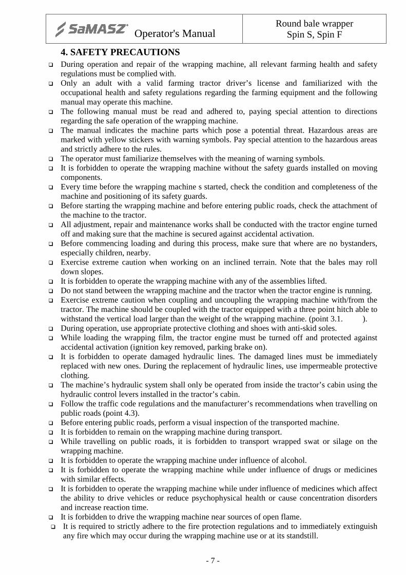
4. SAFETY PRECAUTIONS � During operation and repair of the wrapping machine, all relevant farming health and safety
regulations must be complied with. � Only an adult with a valid farming tractor driver’s license and familiarized with the
occupational health and safety regulations regarding the farming equipment and the following manual may operate this machine.
� The following manual must be read and adhered to, paying special attention to directions regarding the safe operation of the wrapping machine.
� The manual indicates the machine parts which pose a potential threat. Hazardous areas are marked with yellow stickers with warning symbols. Pay special attention to the hazardous areas and strictly adhere to the rules.
� The operator must familiarize themselves with the meaning of warning symbols. � It is forbidden to operate the wrapping machine without the safety guards installed on moving
components. � Every time before the wrapping machine s started, check the condition and completeness of the
machine and positioning of its safety guards. � Before starting the wrapping machine and before entering public roads, check the attachment of
the machine to the tractor. � All adjustment, repair and maintenance works shall be conducted with the tractor engine turned
off and making sure that the machine is secured against accidental activation. � Before commencing loading and during this process, make sure that where are no bystanders,
especially children, nearby. � Exercise extreme caution when working on an inclined terrain. Note that the bales may roll
down slopes. � It is forbidden to operate the wrapping machine with any of the assemblies lifted. � Do not stand between the wrapping machine and the tractor when the tractor engine is running. � Exercise extreme caution when coupling and uncoupling the wrapping machine with/from the
tractor. The machine should be coupled with the tractor equipped with a three point hitch able to withstand the vertical load larger than the weight of the wrapping machine. (point 3.1. ).
� During operation, use appropriate protective clothing and shoes with anti-skid soles. � While loading the wrapping film, the tractor engine must be turned off and protected against
accidental activation (ignition key removed, parking brake on). � It is forbidden to operate damaged hydraulic lines. The damaged lines must be immediately
replaced with new ones. During the replacement of hydraulic lines, use impermeable protective clothing.
� The machine’s hydraulic system shall only be operated from inside the tractor’s cabin using the hydraulic control levers installed in the tractor’s cabin.
� Follow the traffic code regulations and the manufacturer’s recommendations when travelling on public roads (point 4.3).
� Before entering public roads, perform a visual inspection of the transported machine. � It is forbidden to remain on the wrapping machine during transport. � While travelling on public roads, it is forbidden to transport wrapped swat or silage on the
wrapping machine. � It is forbidden to operate the wrapping machine under influence of alcohol. � It is forbidden to operate the wrapping machine while under influence of drugs or medicines
with similar effects. � It is forbidden to operate the wrapping machine while under influence of medicines which affect
the ability to drive vehicles or reduce psychophysical health or cause concentration disorders and increase reaction time.
� It is forbidden to drive the wrapping machine near sources of open flame. � It is required to strictly adhere to the fire protection regulations and to immediately extinguish
any fire which may occur during the wrapping machine use or at its standstill.
Operator's Manual
Round bale wrapper Spin S, Spin F
- 8 -
NOTE:Failure to comply with above instructions may lead to serious injury or death.
4.2. Hazards
Description of residual risks Residual risk results from incorrect actions of the wrapping machine‘s operator. The greatest hazards occur during the following forbidden actions: � installation of the wrapping machine on tractors which do not meet the required minimum
criteria stated in this manual, � standing below raised lifting components of the machine, � standing in the machine‘s working area, � maintenance or repairs conducted with the tractor engine on, � use of damaged hydraulic lines, � machine operation by an operator standing outside the tractor‘s cabin, � operating a wrapping machine which is damaged or without protective covers in place, � operating the wrapping machine on slopes with an inclination exceeding 8°, � transporting bales of silage on the wrapping machine, � remaining on (aboard) the machine when it is working or during transport, � misuse of the wrapping machine, � leaving the wrapping machine unsecured on inclined terrain, � standing between the tractor and the machine while the engine is running.
With the aforementioned residual risks, the bale wrapping machine is regarded as a machine which has been designed and built according to the current state of technology.
Assessment of residua rick
Follow these guidelines: � Read and understand the operating manual, � Do not stand below the raised lifting components of the machine, � Do not stand in the machine‘s working area, � The maintenance and repairs of the wrapping machine should performed at authorized service
workshops, � The machine should be used by trained and authorized operators, Protect the wrapping machine
from access by children and bystanders.
NOTE:The residual risks are present when the aforementioned manufacturer‘s rules and indications are not followed.
During operation, the operator is not subject to noise which may cause the loss of hearing, as the noise level of the machine does not exceed 70 dB and the operator works inside the tractor‘s cabin.
During the operation, the operator is not subject to harmful vibration as the vibration level transferred to the upper limbs does not exceed 2,5 m/s2, and the vibration level transferred to the body is lower than 0,5 m/s2 and the operator is positioned in the tractor‘s cabin.
4.3. Bale loading The wrapping machine is suitable for road and rail transport using carriers with appropriate
load bearing capacity. For loading on a means of road transport, use lifting devices with lifting capacity appropriate
for the machine’s weight including a loaded roll of film. It is forbidden to load the wrapping machine with a bale of swat or silage on it. The transported wrapping machine must be securely fastened to the carrier vehicle. It is forbidden to transport the wrapping machine with a bale of silage or swath loaded on it.
Operator's Manual
Round bale wrapper Spin S, Spin F
- 9 -
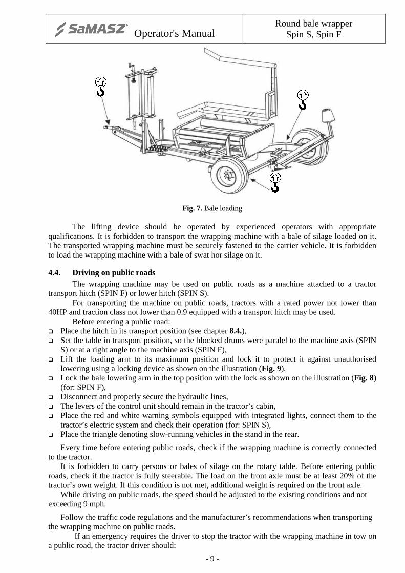
Fig. 7. Bale loading The lifting device should be operated by experienced operators with appropriate
qualifications. It is forbidden to transport the wrapping machine with a bale of silage loaded on it. The transported wrapping machine must be securely fastened to the carrier vehicle. It is forbidden to load the wrapping machine with a bale of swat hor silage on it.
4.4. Driving on public roads The wrapping machine may be used on public roads as a machine attached to a tractor transport hitch (SPIN F) or lower hitch (SPIN S). For transporting the machine on public roads, tractors with a rated power not lower than 40HP and traction class not lower than 0.9 equipped with a transport hitch may be used. Before entering a public road: � Place the hitch in its transport position (see chapter 8.4.), � Set the table in transport position, so the blocked drums were paralel to the machine axis (SPIN
S) or at a right angle to the machine axis (SPIN F), � Lift the loading arm to its maximum position and lock it to protect it against unauthorised
lowering using a locking device as shown on the illustration (Fig. 9), � Lock the bale lowering arm in the top position with the lock as shown on the illustration (Fig. 8)
(for: SPIN F), � Disconnect and properly secure the hydraulic lines, � The levers of the control unit should remain in the tractor’s cabin, � Place the red and white warning symbols equipped with integrated lights, connect them to the
tractor’s electric system and check their operation (for: SPIN S), � Place the triangle denoting slow-running vehicles in the stand in the rear.
Every time before entering public roads, check if the wrapping machine is correctly connected to the tractor.
It is forbidden to carry persons or bales of silage on the rotary table. Before entering public roads, check if the tractor is fully steerable. The load on the front axle must be at least 20% of the tractor’s own weight. If this condition is not met, additional weight is required on the front axle.
While driving on public roads, the speed should be adjusted to the existing conditions and not exceeding 9 mph.
Follow the traffic code regulations and the manufacturer’s recommendations when transporting the wrapping machine on public roads.
If an emergency requires the driver to stop the tractor with the wrapping machine in tow on a public road, the tractor driver should:

Operator's Manual
Round bale wrapper Spin S, Spin F
- 10 -
� Stop the vehicle without causing any danger to the road users, � stop the vehicle as close to the road edge as possible and parallel to the road axis, � turn off the engine, remove the ignition key, engage the parking brake and place wedges
under the wrapping machine’s wheels, � outside a built-up area, the warning triangle should be placed 98' 5"- 164' behind the vehicle
and the emergency lights must be activated, � inside a built-up area, turn on the emergency lights and place the warning triangle behind the
vehicle unless it is already installed on it; make sure that the triangle is visible to other road users,
� in the event of a breakdown, take the required precautions to ensure safety in the area.
Fig. 8. SPIN F in transport position
Fig. 9. SPIN S in transport position
4.5. Warning signs and their meanings
NOTE: a) all warning decals (labels) should be clean and legible, b) lost or damaged decals (labels) must be replaced with new ones, c) new decals (labels) may be ordered at the manufacturer.

Operator's Manual
Round bale wrapper Spin S, Spin F
- 11 -
1. Refer to the operating manual before performing this action
2. Turn off the engine and remove the ignition key
before servicing or repairs
3. Do not stand near the links of the operating wrapping
machine
4. Do not open or remove the safety covers during machine
operation
5. Do not touch the spinning elements during machine
operation
6. Do not approach the working machine. Danger of being
crushed by a bale
7. Keep a safe distance from the raised arm. Danger of being
crushed
8. Dangerous zone. Before operating install a suppert
9. Warning label
NOTE!
SHARP KNIFE
10. Warning label 11. Attacchment points for loading on a means of
transport
12. Film wrapping diagram
13. Proper location of the bale counter sensor below the
magnet
14. Lubrication point 15. Danger of crushing
NOTE! IT IS FORBIDDEN FOR BYSTANDERS TO REMAIN NEAR THE
OPERATING MACHINE.
Operator's Manual
Round bale wrapper Spin S, Spin F
- 12 -
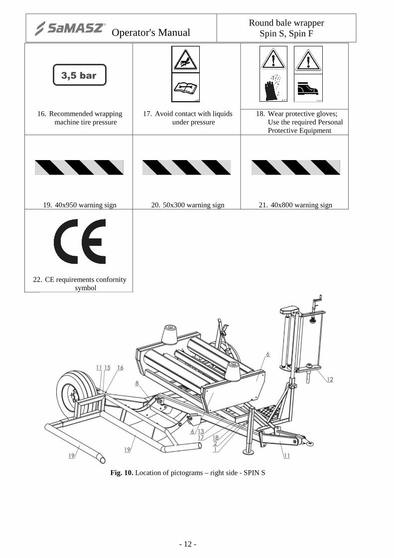
3,5 bar
16. Recommended wrapping machine tire pressure
17. Avoid contact with liquids under pressure
18. Wear protective gloves; Use the required Personal Protective Equipment
19. 40x950 warning sign 20. 50x300 warning sign 21. 40x800 warning sign
22. CE requirements confornity symbol
Fig. 10. Location of pictograms – right side - SPIN S

Operator's Manual
Round bale wrapper Spin S, Spin F
- 13 -
Fig. 11. Location of pictograms – left side - SPIN S
Fig. 12. Location of pictograms – right side - SPIN
Fig. 13. Location of pictograms – left side - SPIN F

Operator's Manual
Round bale wrapper Spin S, Spin F
- 14 -
5. DRIVE OPERATION
5.1. Drive coupling
The bale wrapping machine should be coupled with tractors with rated power not lower than 40HP and traction class 0.9 equipped with a three point hitch. The wrapping machine SPIN F shall be coupled to the lower hitch or to the upper hitch allowing for the maximum vertical load of 1.2 kN. The wrapping machine SPIN S shall be coupled to the lower hitch or to the upper hitch allowing for the maximum vertical load of 4.7 kN.
CAUTION! Make sure that there are no bystanders, especially children, in the coupling area.
NOTE: Before coupling the equipment, place the tractor axis in the machine‘s axis on a hard, flat, level ground. Turn off the tractor engine, remove the ignition key and engage the tractor parking brake. Level the wrapping machine by selecting the appropriate adjustment opening in the hitch.
CAUTION! Couple the hitch-ring only with the lower hitch and check whether the machine is properly connected and secured against accidental disconnection. CAUTION! Make sure that the tractor‘s hydraulic system is sealed.
Connect the electric power source. Check if the operating and signalling systems work properly. Connect the hydraulic power source. Check if the hydraulic systems work properly, especially the lifting and blocking mechanisms responsible for controlling the working and transport positions. Load the first bale and make sure that the vertical load on the tractor’s front axle is larger than 20% of the tractor;s weight. The tractor should remain fully steerable. 5.1.1. Coupling with the upper transport hitch – for: SPIN S The wrapping machine may be coupled with tractors equipped with an upper transport hitch able to transfer vertical loads in excess of 4,7 kN (470 kG). In order to attach the machine to the tractor upper hitch, follow these steps: � Set the suport stand (4) of the wrapping machine in a position which allows the front of the
frame to rest on the ground as shown in the illustration Fig. 14.
Fig. 14. Drawbar set for connection with the lower hitch

Operator's Manual
Round bale wrapper Spin S, Spin F
- 15 -
Fig. 15. Drawbar set for connection with the upper hitch
� Change the position of the transport hitch in the following way:
o Undo the four nuts and remove the M16 bolts, o Rotate the transport hitch by 180°, o Place the M16 screws in the openings and tighten them, o Unscrew the M12 screws holding the hitch-ring, o Rotate the hitch-ring by 180°, o Tighten the M12 screws fixing the hitch-ring.
� Level the wrapping machine by selecting the appropriate adjustment opening in the hitch.
Connect the hitch-ring with the upper hitch. Check if the coupling is properly connected and secured against accidental disconnection.
� Connect the hydraulic power source. Check if the hydraulic systems work properly, especially the lifting and blocking mechanisms responsible for controlling the working and transport positions.
� Make sure that the hydraulic system is sealed. � Connect the electric power source. Check if the operating and signalling systems work properly.
5.2. Disconnecting the drive
CAUTION! Make sure that there are no bystanders, especially children, in the wrapping machine’s storage area and its vicinity.
� Place the wrappimg machine for storage on a hard, flat and level ground. � Turn off the tractor engine, remove the ignition key and engage the tractor’s parking brake. � Disconnect the electric power supply. � Disconnect the hydraulic system. � Lower the main frame support. � Disconnect the hitch-ring from the transport hitch. � Make sure that the machine will not move accidentally.

Operator's Manual
Round bale wrapper Spin S, Spin F
- 16 -
6. COMMISSIONING The commissioning of a newly purchased bale wrapping machine should be performer under the supervision of an experienced operator or a dealer’s service representive.
IMPORTANT: Before commissioning, familiarize yourself with the following manual, paying special attention to the fragments regarding the safety of the operator and bystanders.
Before each start up of the wrapping machine, the control levers shall be installed in the tractor’s cabin.
6.1. Commissioning of the counter The wrap counter shall be installed in the tractor‘s cabin, connected to the revolution sensor
and attached to the electric power source using the power cable. The proper connection is signalled by a blinking red light on the counter display. Press and hold the buton (activation symbol C). Each activation of the counter is accompanied by the display test and power supply voltage test. The display will show the indication 8888 and all decimal points and LEDs will light up, additionally the sound signal will be activated. Then, the power source voltage will be displayed e.g. U12.7, which denotes voltage of 12.7V. Every other condition indicates that the counter is damaged.
Then the year of manufacture of the counter will be displayed e.g. 2011 and a yellow LED
will light up (1).Using the F2 button enter the year of manufacture of the wrapping machine (between 2000 and 2099). Pass to setting the wrapping machine serial numer with F1. A flashing LED (2) signals the option of setting the wrapping machine option. Enter the serial number pressing and holding F2 button (range from 0000 to 9999). Check if the entered data is correct by pressing the F1 button. It should display the year of manufacture and the wrapping machine serial number in an alternate way. If the entered data is correct, confirm using the on/C button by pressing and holding it for about 10 seconds. The confirmation of the entered data will be signalled by a blinking red LED and intermittent sound signal. It is only possible to enter the year of manufacture and serial number once. After the information is confirmed, it cannot be corrected. To stop the data entering procedure, disconnect the counter from its power source. The wrap counter data cannot be erased and no changes can be made.
Operator's Manual
Round bale wrapper Spin S, Spin F
- 17 -
7. CONTROLS AND ONGOING ADJUSTMENTS
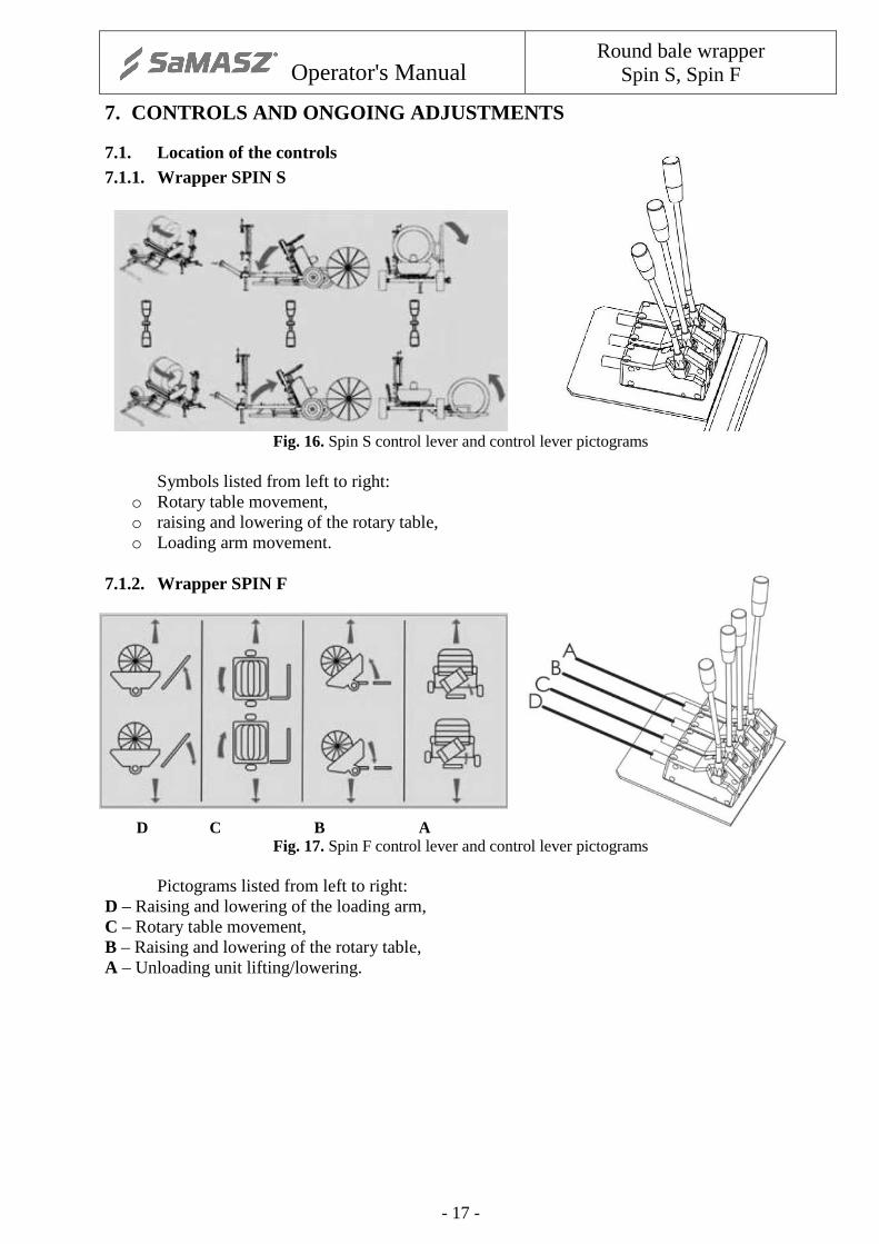
7.1. Location of the controls 7.1.1. Wrapper SPIN S
Fig. 16. Spin S control lever and control lever pictograms Symbols listed from left to right:
o Rotary table movement, o raising and lowering of the rotary table, o Loading arm movement.
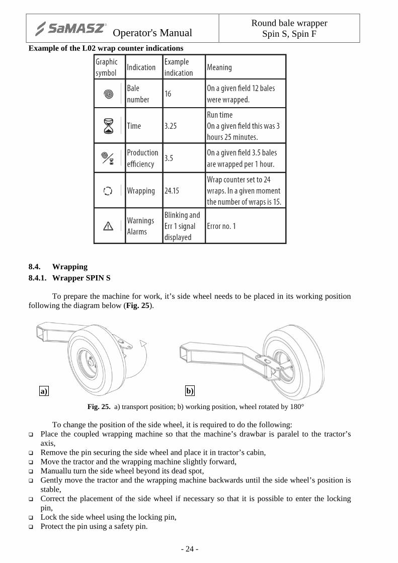
7.1.2. Wrapper SPIN F
D C B A Fig. 17. Spin F control lever and control lever pictograms
Pictograms listed from left to right: D – Raising and lowering of the loading arm, C – Rotary table movement, B – Raising and lowering of the rotary table, A – Unloading unit lifting/lowering.

Operator's Manual
Round bale wrapper Spin S, Spin F
- 18 -
7.2. Location of ongoing adjustment points
Fig. 18. Wrapping film feeder
With each revolution of the rotating frame, the bale and film rotate by a certain angle around the horizontal axis, which causes the consecutive layers of film to be wrapped tightly around the bale.
Fig. 19. Film movement diagram

Operator's Manual
Round bale wrapper Spin S, Spin F
- 19 -
7.2.1. Wrapper SPIN S
1 – Levelling of the wrapping machine during coupling with the tractor.
2 – Chain tightening. 3 – Lubricating point symbols are located on
the machine. 4 – Intersecting axis gear. 5 – Hydraulic control unit. 6 – The revolutions sensor is marked with a
symbol located on the machine.
Fig. 20. SPIN S control and currentadjustment elements
7.2.2. Wrapper SPIN F
Fig. 21. SPIN F control and current adjustment elements

Operator's Manual
Round bale wrapper Spin S, Spin F
- 20 -
8. WRAPPING MACHINE OPERATION
8.1. Installing the film
Place the film roll on the feeder pin in the following order (see diagram: � Deflect the support with the metal rollers and secure it using the hook attached to the wrapping
assembly. � Using a lever (crank) undo the upper pin pressing the film upwards. � Set the height of the lower pin in position appropriate for the film roll width (1' 8" or 2' 5"). � Place the film roll on the lower conic pin. � Clamp the roll by turning the lever (crank) on the upper pin so that the roll is securely held in
the vertical position. � Protect the roll from unscrewing using the nut on the crank screw. � When installing the roll of film, place its internal sticky side towards the bale axis. � Properly set the initial tightening of the film (Punkt 8.4). � Pull the film through the rubber rollers as indicated on the diagram located on the gear cover. � Pull the end of the film so that it may be easily handled in the machine.
The wrapping machine is pre-set to use 1' 8" film. To use 2' 5" film, the chain wheel must be
replaced (Fig. 22). To do so, it is required to: � Unscrew the 4 M12 hub nuts, remove the side cover of the rotating frame (on the side of the
chain transmission), � Loosen the M12 screw on the chain tightening mechanism, � Remove the chain from the Z17 chain wheel installed on the main shaft and remove the split pin
securing the wheel, � Remove the Z17 chain wheel form the shaft (using an appropriate tool), � Secure the removed Z 17 chain wheel, � Replace it with a Z27 chain wheel, � Secure the Z27 repeating the above procedurę in the reverse order.
Fig. 22. Replacement of chain wheel

Operator's Manual
Round bale wrapper Spin S, Spin F
- 21 -
8.2. Hydraulic system
The wrapping machine’s hydraulic system is powered from the tractor’s hydraulic system. To attach the machine to the tractor’s hydraulic system, the attachment cables are connected to the hydraulic controls and further to the wrapping machine’s hydraulic motor.
Through the chain transmission, the hydraulic motor rotates the drums with the loaded silage bales. By means of the three-section hydraulic control unit (1), the hydraulic engine powers 5 double-acting cylinders responsible for:
� tilting the rotary table and the unloading unit to the vertical and horizontal position, � raising and lowering of the loading arm, � rotation of the rotary table. The control over the engine and hydraulic cylinders is ensured using the control levers located
in the tractor’s cabin during operation. These levers are connected to the three-section control unit using Bowden cables.
The symbols on the support inform about the functions fulfilled by each lever on the control unit (1). The three section control unit (1) is protected against high pressure from the hydraulic system by means of a safety valve (1) (SPIN S), four section control unit (SPIN F). The 3-sectional control unit (1) (SPIN S) or 4-sectional (SPIN F) is protected against high pressure from the hydraulic system by means of a safety valve. The valve indicated on the illustration Fig. 23 item (2) is located in the rotating frame section and operates only in the table rotation system rotating clockwise, which is opposite to the wrapping direction. Its task is to smoothly stop the rotating frame.
a)
b)
Fig. 23. Hydraulic system – a) SPIN S; b) SPIN F

Operator's Manual
Round bale wrapper Spin S, Spin F
- 22 -
8.3. Wrap counter 8.3.1. Wrap counter system Wrap counter L-02 The wrap counter is an electronic device used for counting the wraps on a bale and may be used on all types of wrapping machines. The wrap counter should be installed in the tractor’s cabin in a place where it is visible and accessible to the operator. The counter kit comprises of:
1) Pre-programmed counter in a plastic casing, 2) Revolution sensor, 3) Bundle of wires, 4) Multi-contact connection.
Fig. 24. Wrap counter Protect the counter against humidity, excessive vibration and hitting the cabin elements, and especially against falling on a hard surface. The counter can be fixed using its back surface catch.
WARNING! Protect the meter from water, chemical agents, direct atmospheric precipitation, frost, high temperature in excess of 50°C and direct exposure to sunlight.
The revolution sensor attached to an unmoving part of the wrapping machine operates in conjunction with a magnet attached to the rotary frame which passes impulses to the revolution counter. Each rotation of the bale is counted and displayed on the revolution counter display. When the programmed number of revolutions is performed, the counter signals the completion of the wrapping process with a blinking light and sound signal. The counter may be programmed to a required number of revolutions between 10 and 49. Revolution sensor Connect the revolution sensor installed in the cabin to the power source (12V) and revolution sensor using the specially prepared bundle of wires.

Operator's Manual
Round bale wrapper Spin S, Spin F
- 23 -
CAUTION! Protect the wires connecting the sensor with the revolution counter against accidental mechanical damage.
CAUTION! Protect the connections of the wires with the revolution counter against accidental uncoupling.
8.3.2. Switching the system on and off
The blinking red signalling light indicates that the revolution counter system has been configured properly.
Press and hold the ON buton marked with the letter C. Each activation od the counter is accompanied by the display test and the power supply
voltage test. A positive test result indicates the unit is ready to work with the settings entered during the previous use.
Press and hold the C button until a red blinking light appears on the display (for about 3 seconds). After this signal, the counter unit may be disconnected.
8.3.3. Working with the counter in counting mode
Setting the wrap number Press the F1 and F2 buttons at the same time. The last settings shall be displayed. The setting mode is signalled by the activation of two LEDs, red – warning and green - wrapping.
Change the number of wraps using the F2 button (within the scope of 10 to 49 wraps). Confirm using the C button. The counter is ready to work with its new settings.
Field selection Change the field number using the F1 button (1, 2, 3). Change the stored bale indication for a given field using the F2 - set the number of wraps and the numer of bales. Additionally, the F2 button can display the average efficiency of the wrapping machine during a working hour. After the field number is selected, erase the counter indication by simultaneously pressing the F2 and C buttons. When the device is ready to enter changes, the red LED will light up and a sound signal will be emitted. Hold both buttons pressed until the sound signal is heard. The indications for the given field have been erased. Operation of the counter in counting mode Start work after selecting the field and setting the number of wraps. The counter indicates wrapping as soon as it receives impulses from the wrapping machine’s sensor. After a set number of wraps is reached, the red LED and the counter display begin to blink. A complete wrap is also signalled by an intermittent sound signal. Erase the wrapping end signal by pressing and holding the C button. Hold the buton until the display indicates the numer of wrapped bales and the red LED turns off. The counter is ready for counting wraps on another bale.
Operator's Manual
Round bale wrapper Spin S, Spin F
- 24 -
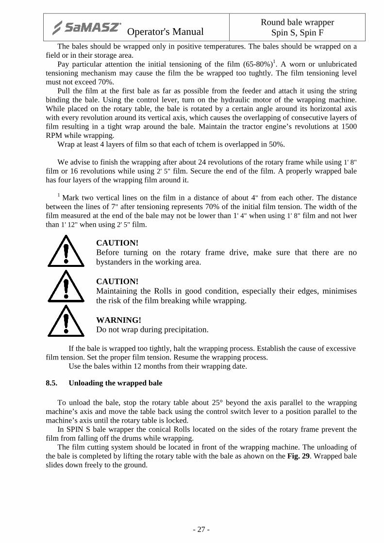
Example of the L02 wrap counter indications
8.4. Wrapping 8.4.1. Wrapper SPIN S
To prepare the machine for work, it’s side wheel needs to be placed in its working position
following the diagram below (Fig. 25).
Fig. 25. a) transport position; b) working position, wheel rotated by 180° To change the position of the side wheel, it is required to do the following:
� Place the coupled wrapping machine so that the machine’s drawbar is paralel to the tractor’s axis,
� Remove the pin securing the side wheel and place it in tractor’s cabin, � Move the tractor and the wrapping machine slightly forward, � Manuallu turn the side wheel beyond its dead spot, � Gently move the tractor and the wrapping machine backwards until the side wheel’s position is
stable, � Correct the placement of the side wheel if necessary so that it is possible to enter the locking
pin, � Lock the side wheel using the locking pin, � Protect the pin using a safety pin.
a) b)

Operator's Manual
Round bale wrapper Spin S, Spin F
- 25 -
WARNING! Be careful while changing the position of the side wheel. There is a risk of the operator’s hand being crushed.
8.4.2. Wrapper SPIN F To prepare the machine for work the wrapping machine drawbar needs to be placed in its
working position following the diagram bellow Fig. 26.
Fig. 26. Preparing the machine to work – a) transport position; b) working position
Set to the working position with a drawbar coupled with the tractor transport hitch. Proceed as follows at changing the drawbar position:
� Aling the coupled wrapping machine with the tractor axis, � Remove the drawbar security pin (back part of the drawbar), � Lock the right road wheel of the machine, � Slowly move the tractor with the machine forward until the security pin is in the working
position sleeve axis, � Lock the drawbar in the working position with a pin, � Unlock the loading arm, � Unlock the unloading unit, � Place the loading arm and unloading arm locks in the specified places.
WARNING! Be careful while changing the position of the side wheel. There is a risk of the operator’s hand being crushed.
8.4.3. Bale loading Lower the loading arm to its maximum lower position i.e. horizontal position when it is approx. 4" above ground in its maximum deflection. Place the rotary frame perpendicular to the driving direction so that the film cutting cutter is in front of the machine. Stop the rotary table about 25° beyond the axis parallel to the wrapping machine axis and move the table back using the control switch lever to a position parallel to the machine axis until the rotary table is locked. Move towards the bale as shown in the drawing below Fig. 27 and Fig. 28.
NOTE: The tractor approaching the bale should drive paralel to the bale’s axis so that the axis of the loading arm faces the axis of the bale being loaded (SPIN S). NOTE: The axis of the wrapping machine moving forward should be perpendicular to the loaded bale axis and the lowered arm should hold the bale (SPIN F).
a) b)

Operator's Manual
Round bale wrapper Spin S, Spin F
- 26 -
Fig. 27. SPIN S bale loading
Fig. 28. SPIN F bale loading
Stop the tractor when the bale rests against the stop plate of the lateral loading arm. Lift the grab arm until the bale rolls freely onto the wrapping machine rotary table. Lower the grabbing arm to the bottom when the bale rests on the rotary table. Consecutive bales are loaded from the ground to the wrapping machine rotary table in the same way.
Lower the grabbing arm to the bottom when the bale rests on the roatry table.
WARNING! Before operation check: � Whether the wrapping machine drawbar is properly connected to the tractor transport
hitch, � Whether the power hydraulic lines are properly connected, � Whether the revolutions counter system is properly connected, � Raising and lowering of the loading arm, � Whether the rotary table is placed in its vertical and horizontal position correctly, � Smoothness and direction of the rotary frame and drums movement – the rotary
frame should rotate counterclockwise, � Tightening of the wrapping machine side wheel pins.
Operator's Manual
Round bale wrapper Spin S, Spin F
- 27 -
The bales should be wrapped only in positive temperatures. The bales should be wrapped on a field or in their storage area.
Pay particular attention the initial tensioning of the film (65-80%)1. A worn or unlubricated tensioning mechanism may cause the film the be wrapped too tughtly. The film tensioning level must not exceed 70%.
Pull the film at the first bale as far as possible from the feeder and attach it using the string binding the bale. Using the control lever, turn on the hydraulic motor of the wrapping machine. While placed on the rotary table, the bale is rotated by a certain angle around its horizontal axis with every revolution around its vertical axis, which causes the overlapping of consecutive layers of film resulting in a tight wrap around the bale. Maintain the tractor engine’s revolutions at 1500 RPM while wrapping.
Wrap at least 4 layers of film so that each of tchem is overlapped in 50%. We advise to finish the wrapping after about 24 revolutions of the rotary frame while using 1' 8"
film or 16 revolutions while using 2' 5" film. Secure the end of the film. A properly wrapped bale has four layers of the wrapping film around it.
1 Mark two vertical lines on the film in a distance of about 4" from each other. The distance
between the lines of 7" after tensioning represents 70% of the initial film tension. The width of the film measured at the end of the bale may not be lower than 1' 4" when using 1' 8" film and not lwer than 1' 12" when using 2' 5" film.
CAUTION! Before turning on the rotary frame drive, make sure that there are no bystanders in the working area. CAUTION! Maintaining the Rolls in good condition, especially their edges, minimises the risk of the film breaking while wrapping. WARNING! Do not wrap during precipitation.
If the bale is wrapped too tightly, halt the wrapping process. Establish the cause of excessive film tension. Set the proper film tension. Resume the wrapping process. Use the bales within 12 months from their wrapping date.
8.5. Unloading the wrapped bale
To unload the bale, stop the rotary table about 25° beyond the axis parallel to the wrapping machine’s axis and move the table back using the control switch lever to a position parallel to the machine’s axis until the rotary table is locked.
In SPIN S bale wrapper the conical Rolls located on the sides of the rotary frame prevent the film from falling off the drums while wrapping.
The film cutting system should be located in front of the wrapping machine. The unloading of the bale is completed by lifting the rotary table with the bale as ahown on the Fig. 29. Wrapped bale slides down freely to the ground.

Operator's Manual
Round bale wrapper Spin S, Spin F
- 28 -
Fig. 29. Bale discharge a) SPIN S; b) SPIN F In SPIN F bale wrapper during the unloading proces, the cutter cuts away the film. The bale on the unloading unit rotation control level as shown in the Fig. 30. After unloading the bale, all working components should return to their position. Another bale may now be loaded.
Fig. 30. Bale discharge – SPIN F Correct discharge sequence in SPIN F: lifting of the unloading unit (1), tilting of the rotary table (2), lowering of the unloading unit (3) and lowering of the rotary table (4) (Fig. 29b). 8.5.1. Film cutting
If the film cutter fails to operate correctly, stop the wrapping machine, turn off the tractor engine, remove the ignition key and engage the tractor parking brake. Adjust the cutter angle (1) in relations to the film in the clamp (2). The adjustment is made using the tightening screw (3). When the srew (3) is turned clockwise, the cutter angle in relations to the film is decreased and the other way round.
a) b)

Operator's Manual
Round bale wrapper Spin S, Spin F
- 29 -
Fig. 31. Film cutting A properly set cutter cuts the film when the unloaded bale touches the ground. When the angle is too steep, the film is not cut even though the bale is unloaded to the
ground.
WARNING! Lower the control lever on the hydraulic control unit when there is danger caused by the wrapping machine. Turn off the tractor engine, remove the ignition key and engage the tractor parking brake. Locate the hazard and remove it.
WARNING! Lock the rotary table during loading and unloading of the bale. WARNING! Take extra caution when adjusting the cutter. The cutter is extremely sharp. Danger of hand injury.
Side wheels located on the sides of the rotary frame prevent the bale from falling off the
drums while wrapping.
8.5.2. Bale vertical positioning system – optional equipment SPIN S model
As optional supply, a bale vertical positioning system is available. This device allows to position the wrapped bale vertically during unloading, in order to properly place it in the silage storing location. By doing so, we eliminate the risk of damage to the film during transport from the wrapping location to te storage location. This element may be purchased together with the machine or at a later, convenient date. The positioning system allows the placement of bales on the left or right side of the wrapping machine. The bale vertical positioning system is installed in a way shown on the Fig. 32.
Operator's Manual
Round bale wrapper Spin S, Spin F
- 30 -
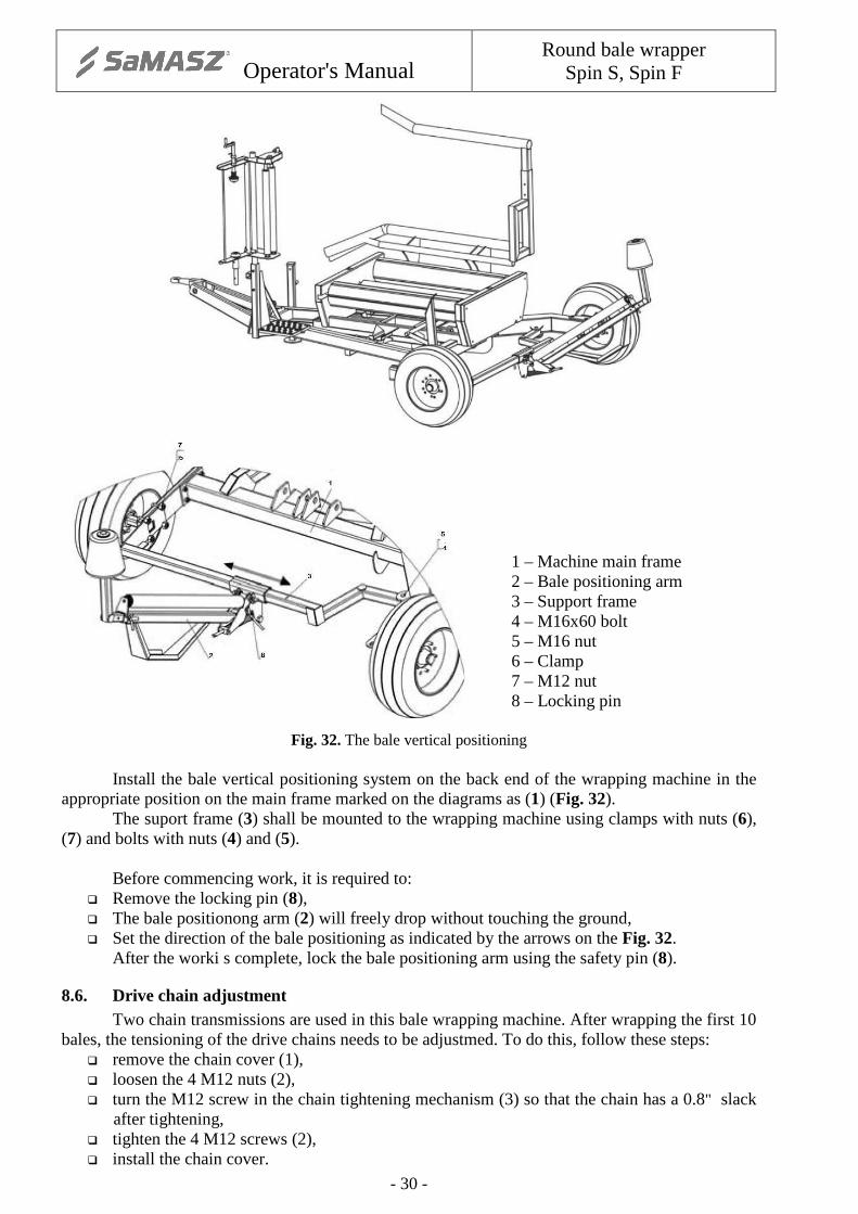
1 – Machine main frame 2 – Bale positioning arm 3 – Support frame 4 – M16x60 bolt 5 – M16 nut 6 – Clamp 7 – M12 nut 8 – Locking pin
Fig. 32. The bale vertical positioning
Install the bale vertical positioning system on the back end of the wrapping machine in the appropriate position on the main frame marked on the diagrams as (1) (Fig. 32). The suport frame (3) shall be mounted to the wrapping machine using clamps with nuts (6), (7) and bolts with nuts (4) and (5). Before commencing work, it is required to:
� Remove the locking pin (8), � The bale positionong arm (2) will freely drop without touching the ground, � Set the direction of the bale positioning as indicated by the arrows on the Fig. 32.
After the worki s complete, lock the bale positioning arm using the safety pin (8).
8.6. Drive chain adjustment Two chain transmissions are used in this bale wrapping machine. After wrapping the first 10 bales, the tensioning of the drive chains needs to be adjustmed. To do this, follow these steps:
� remove the chain cover (1), � loosen the 4 M12 nuts (2), � turn the M12 screw in the chain tightening mechanism (3) so that the chain has a 0.8" slack
after tightening, � tighten the 4 M12 screws (2), � install the chain cover.

Operator's Manual
Round bale wrapper Spin S, Spin F
- 31 -
Fig. 33. Drive chain adjustment Check the tightening and the chain conditio periodically after wrapping every 120 bales.
8.7. Finishing work
After the worki s complete, disconnect the revolution counter and secure the revolution sensor against humidity. Before storing the wrapping machine for a longer period, place the impulse sensor in a dry storage room. Place the machine on a hard, flat, level ground. Disconnect the hydraulic power source and the electric power supply.
Support the drawbar using a support stand. Disconnect the machine’s drawbar from the tracotr’s hitch.
WARNING! It is forbidden to disconnect the wrapping machine from the tractor when there is a bale on the rotary table.
Clean the machine and inspect its conditio paying special attention to the quality of the paint coat. If it is required to make some touch-ups, it is advised to use the paint repair kit supplied by the manufacturer. Protect the rubber elements, i.e. hydraulic lines, against direct sunlight.

Operator's Manual
Round bale wrapper Spin S, Spin F
- 32 -
9. REGULAR INSPECTION
9.1. User inspection
After every use of the wrapping machine, check: � The conditio and legibility of the data plate and symbols, � Condition of the drawbar, � Hydraulic system leakproofness, � Drive chain of the rotary frame, � Drive chains of the rotary drums.
The nameplate must only be replaced a tan authorised repair shop. Replace the unintelligible symbols with new ones. After the working season is over, grease the drive chain of the rotary frame and the drive chains
of the rotary drums using the LT-43 grease. Send the counter to an authorised service if the casing is damaged. Any attempt to repair the
damaged counter will result in the warranty becoming null and void. Repalce the oil of the intersecting axis gear every two year as follows:
� Place the machine on a level surface, � Place a leakproof tank below the drain plug, � Remove the drain plug, the filler plug and the overflow plug, � After the oil is drained, close the drain plug, � Pour fresh 80W90 hydraulic gear oil to the filler plug level, � Close the filler plug and overflow plug.
The used oil should be sent to a gas station which collects such products.
IMPORTANT: During oil replacement, it is required to wear impermeable protective clothing suitable for contact with oil-based products.
Replace the hydraulic lines every 5 years. Before every working season, check (without a silage bale loaded) the operation of the transmission system by turning on the rotary table, raising and lowering the rotary table and raising and lowering the loading arm.
9.2. Service checks
Periodical service checks shall be perfomed after every two working seasons of machine use.
It is advised to use original replecement parts which will help maintain the wrapping machine in good technical condition for a long time.

Operator's Manual
Round bale wrapper Spin S, Spin F
- 33 -
10. AUTHORISED SERVICE
10.1. Warranty service
The manufacturer issues a warranty on conditions described in the warranty book. During the period covered by the warranty, repairs shall be made at authorised service stations or at the manufacturer’s service.
10.2. Ongoing maintenance
After the period covered by the warranty, authorised service stations perform periodical ispections, adjustments and repairs.
10.3. Ordering replacement parts
Spare parts should be ordered from resellers or directly form the manufacturer stating the name and surname of the user or company name and address, name, symbol, serial numer and year of manufacturere of the machine, catalogue name of the part, catalogue numer, numer of drawing or standard, numer of ordered items and agreed terms of payment.
Operator's Manual
Round bale wrapper Spin S, Spin F
- 34 -
11. WRAPPING MACHINE STORAGE
After yhe working season is over, clean the wrapping machine and check the conditio of the protective paint coating. Touch up the damage to the paint coating at a service workshop. Check the conditio and legibility of the nameplate. If the plate is damaged, notify the service station. Check the conditio and legibility of the symbols. If they are damaged, replace tchem with new ones.
� The wrap counter should be stored in a dry place with the electrical connections protected
against fouling and humidity. � The sensor cable should be folded and stored in a dry place with the electrical connections
protected against fouling and humidity. � Store the wrapping machine on a hard, flat, level ground. � It is advised to store the wrapping machine in a dry location, protecting it against UV rays and
other harmful agents. � If the wrapping machin eis stored without any canopy roof, protect it with a water-resistant
tarpaulin or film.
NOTE: Store the wrapping machine in an atmosphere free of aggresive agents (e.g. ammonia, chemicals).
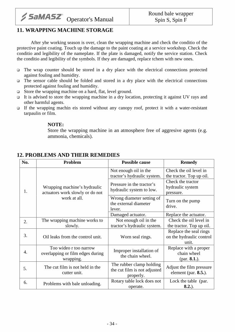
12. PROBLEMS AND THEIR REMEDIES No. Problem Possible cause Remedy
1. Wrapping machine’s hydraulic actuators work slowly or do not
work at all.
Not enough oil in the tractor’s hydraulic system.
Check the oil level in the tractor. Top up oil.
Pressure in the tractor’s hydraulic system to low.
Check the tractor hydraulic system pressure.
Wrong diameter setting of the external diameter lever.
Turn on the pump drive.
Damaged actuator. Replace the actuator.
2. The wrapping machine works to slowly.
Not enough oil in the tractor’s hydraulic system.
Check the oil level in the tractor. Top up oil.
3. Oil leaks from the control unit. Worn seal rings. Replace the seal rings
on the hydraulic control unit.
4. Too wideo r too narrow
overlapping or film edges during wrapping.
Improper installation of the chain wheel.
Replace with a proper chain wheel (par. 8.1.).
5. The cut film is not held in the cutter unit.
The rubber clamp holding the cut film is not adjusted
properly.
Adjust the film pressure element (par. 8.5.).
6. Problems with bale unloading. Rotary table lock does not
operate. Lock the table (par.
8.2.).

Operator's Manual
Round bale wrapper Spin S, Spin F
- 35 -
13. DISASSEMBLY AND WITHDRAWAL FROM USE
During machine disassembly, separate the parts made of the same material. Keep liquids, metal parts, rubber, plastic, separate. Disassembly and disposal of the wrapping machine should be performed by specialised service stations familiarised with the construction and functioning of the machine. Only specialised service stations have a complete and up-to-date knowledge of the applied materials and hazards related to their improper transport and storage. Authorised service stations offer both advice and complete machine disposal services. Use proper tools and auxiliary equipment for the disassembly (jack, lift, wheel extractor).
CAUTION! During oil draining from the gearbox, use caution in order not to corrupt the environment. Keep all the parts secured, preventing any possible hazard. In particular keep the parts away from children and animals.
14. WARRANTY CARD
BALE WRAPPING MACHINE
This product has been checked and deemed fully serviceable and cleared for use.
NOTE: The warranty card missing required seals or signatures or which has been corrected or is illegible is void.
Serial number Manufacture date Guarantor seal Controller signature
Date of sale Seller seal Seller signature

Operator's Manual
Round bale wrapper Spin S, Spin F
- 36 -
15. WARRANTY CONDITIONS
15.1. Warranty claims procedures
1. The manufacturer provides a bale wrapping machine designed and built in compliance with the currently applicable standards. The manufacturer guarantees that the supplied bale wrapping machine is free of manufacturing defects.
2. The manufacturer provides warranty service for 12 months starting from the date of first sale, provided the wrapping machine is used for its intended purpose and the recommendations contained in the manual are followed.
3. The warranty card properly filled in at the Dealership is the confirmation of the manufacturer‘s warranty; the acceptance of the warranty conditions must be confirmed by the customer‘s signature.
4. The quality warranty covers the machine‘s defects caused by defective manufacturing, material defects and latent defects.
5. The warranty does not cover the assemblies and parts which are subject to normal wear (e.g. tyres, brake pads).
6. The warranty does not cover any mechanical damage or other damage resulting from improper use, improper maintenance or improper adjustment of the wrapping machine.
7. The warranty does not cover any damage resulting from improper storage of the machine.
8. Any unauthorised modifications in the construction of the machine introduced by the user will result in automatic termination of the warranty.
9. The manufacturer shall not be held responsible for any loss, damage or destruction of the product resulting from causes other than defects of the supplied machine.
10. During the warranty period the manufacturer will repair any defects which occurred as a result of the manufacturer‘s negligence with the exception of defects listed in paragraphs 5 - 8.
11. The warranty repair shall be made within 14 working days of the notification/ supply of the machine to the designated service station or at other time agreed upon by the parties.
12. The warranty is extended by the time required to complete the repair.
13. During the warranty period all repairs which are not covered by the warranty are performed by the authorized service stations at full cost to the user. Before such repairs, the service station will inform the user of the suggested cost, time and scope of the repair.
14. The decision whether to commence a chargeable repair of the wrapping machine with a warranty valid at the time of repair is made by the Customer.
NOTE: Upon the purchase of machine, request the vendor to carefully complete the warranty card. Date and place of the purchase as well as vendor stamp and signature is needed, otherwise may lead to the warranty loss.
NOTE: Exact address, date and place of purchase, together with invoice number is needed for warranty claim to be processed.
NOTE: Manufacturer reserves the right to change the specification or design of products without notice.

Operator's Manual
Round bale wrapper Spin S, Spin F
- 37 -
15.2. Record of warranty repairs
Repairs performed and parts replaced:
Date, seal and signature of person performing the repair.
Date, seal and signature of person performing the repair.
Date, seal and signature of person performing the repair.