MAGNE-SONICS SERIES 200 Vibrating tuning fork Liquid level ...
Product Data Sheet00813-0100-4130, Rev CANovember 2010 Rosemount 2130
www.rosemount.com
• Designed for operation in temperatures of–94 to 500 °F (–70 to 260 °C)
• Electronic self-checking and condition monitoring - Heartbeat LED gives status and instrument health information
• Increased safety and proven FMEDA suitable for SIL2
• Virtually unaffected by flow, bubbles, turbulence, foam, vibration, solids content, coating, properties of the liquid, and product variations
• Adjustable Switching Delay for turbulent or splashing applications
• “Fast Drip” fork design gives quicker response time especially with viscous liquids
• General area, Explosion-proof/Flameproof, and Intrinsically Safe options
ContentsReliable Performance...In Challenging Applications . . . . . . . . . . . . . . . . . . . . . . . . . .page 2
Rosemount 2130 Enhanced Vibrating Fork Liquid Level Switch . . . . . . . . . . . . . . . . .page 4
Specifications . . . . . . . . . . . . . . . . . . . . . . . . . . . . . . . . . . . . . . . . . . . . . . . . . . . . . . . .page 8
Product Certifications . . . . . . . . . . . . . . . . . . . . . . . . . . . . . . . . . . . . . . . . . . . . . . . . .page 10
Dimensional Drawings . . . . . . . . . . . . . . . . . . . . . . . . . . . . . . . . . . . . . . . . . . . . . . . .page 12
Rosemount 2130 EnhancedVibrating Fork Liquid Level Switch
Product Data Sheet00813-0100-4130, Rev CA
November 2010Rosemount 2130
2
Reliable Performance...In Challenging Applications
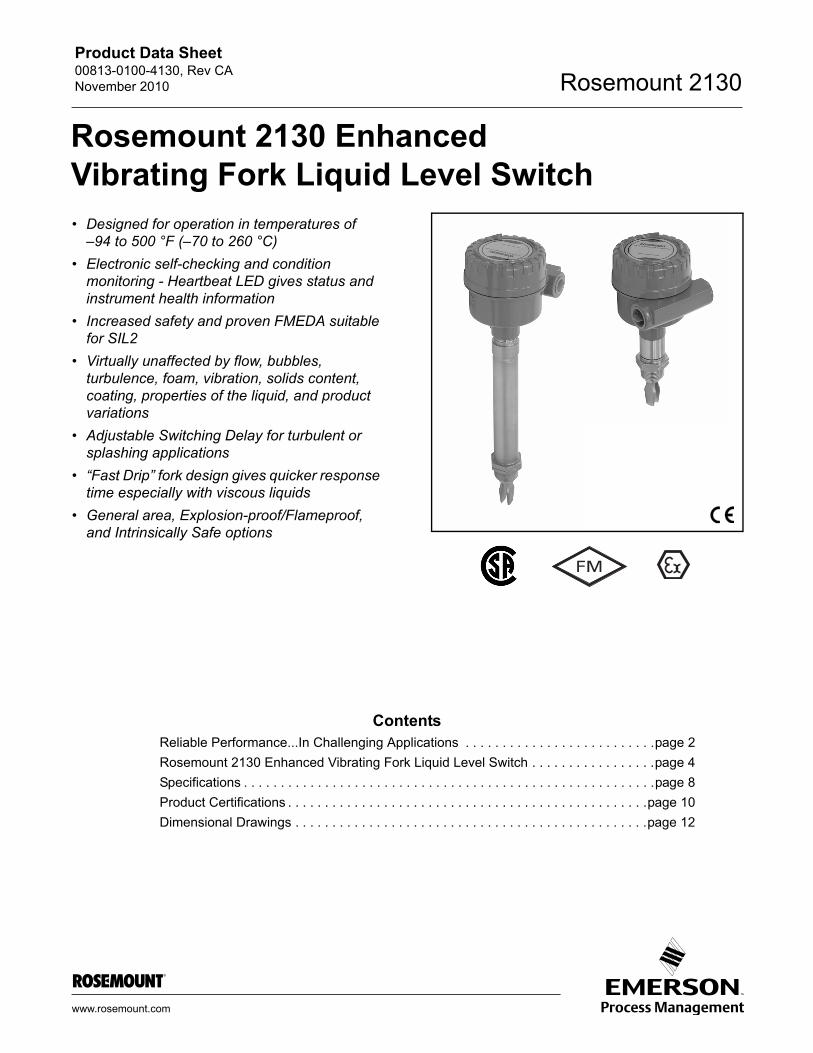
MEASUREMENT PRINCIPLE
The Rosemount 2130 is designed using the principle of a tuning fork. A piezo-electric crystal oscillates the forks at their natural frequency. Changes to this frequency are continuously monitored. The frequency of the vibrating fork sensor changes depending on the medium in which it is immersed. The denser the liquid, the lower the frequency.
When used as a low level alarm, the liquid in the tank or pipe drains down past the fork, causing a change of natural frequency that is detected by the electronics and switches the output state.
When the 2130 is used as a high level alarm, the liquid rises in the tank or pipe, making contact with the fork which then causes the output state to switch.
KEY FEATURES AND BENEFITS
• Virtually unaffected by turbulence, foam, vibration, solids content, coating, or liquid properties
• The mid-range temperature 2130 is designed for operation in temperatures from –40 to 356 °F (–40 to 180 °C)
• The extreme temperature 2130 is designed for operation in temperatures from –94 to 500 °F (–70 to 260 °C). It has astainless steel thermal tube to move the electronics away from the process
• Electronic self-checking and condition monitoring.The ‘heartbeat’ LED gives status and health information on the 2130
• Adjustable switching delay prevents false switching in turbulent or splashing applications
• ‘Fast Drip’ fork design gives quicker response time, especially with viscous liquids
• Rapid wet-to-dry time for highly responsive switching
• Fork shape is optimized for hand polishing to meet hygienic requirements
• No moving parts or crevices for virtually no maintenance
2130***E
2130***M
‘Fast Drip’ Forks
Adjustable Switching Delay
Product Data Sheet00813-0100-4130, Rev CANovember 2010
3
Rosemount 2130
Superior Diagnostics
• Built-in diagnostics continuously check electronic and mechanical health
• Fork conditions detected including internal and external damage, coated or blocked, and extreme corrosion
• Ideal for critical alarm duties
Fit and Forget
• Once installed, the 2130 is ready to go. It needs no calibration and requires minimum installation
• The ‘heartbeat’ LED gives an instant visual indication that the unit is operational
• Functional testing of the instrument and system is easy with a magnetic test point
• You can install, and forget it
Extended High and Low Temperature Performance
• The extreme temperature 2130 enables standardization of Rosemount vibrating fork switches across a wide range of process environments, and is ideally suited for harsh conditions where high reliability is essential
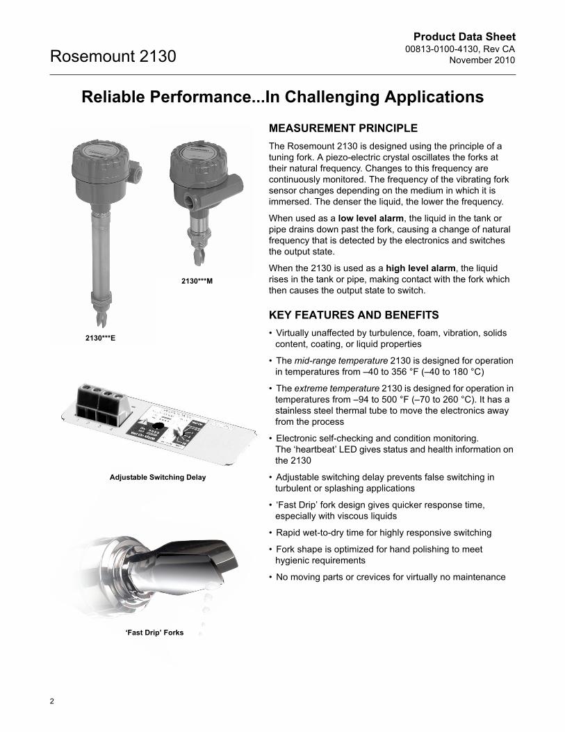
APPLICATIONS
• Overfill protection
• High and low level alarms
• Pump control or limit detection
• Run dry or pump protection
• Hygienic applications
• High temperature applications
• Wireless applications
High And Low Level Alarm
High Temperature Applications
Pump Control / Limit Detection
Wireless Applications
Product Data Sheet00813-0100-4130, Rev CA
November 2010Rosemount 2130
4
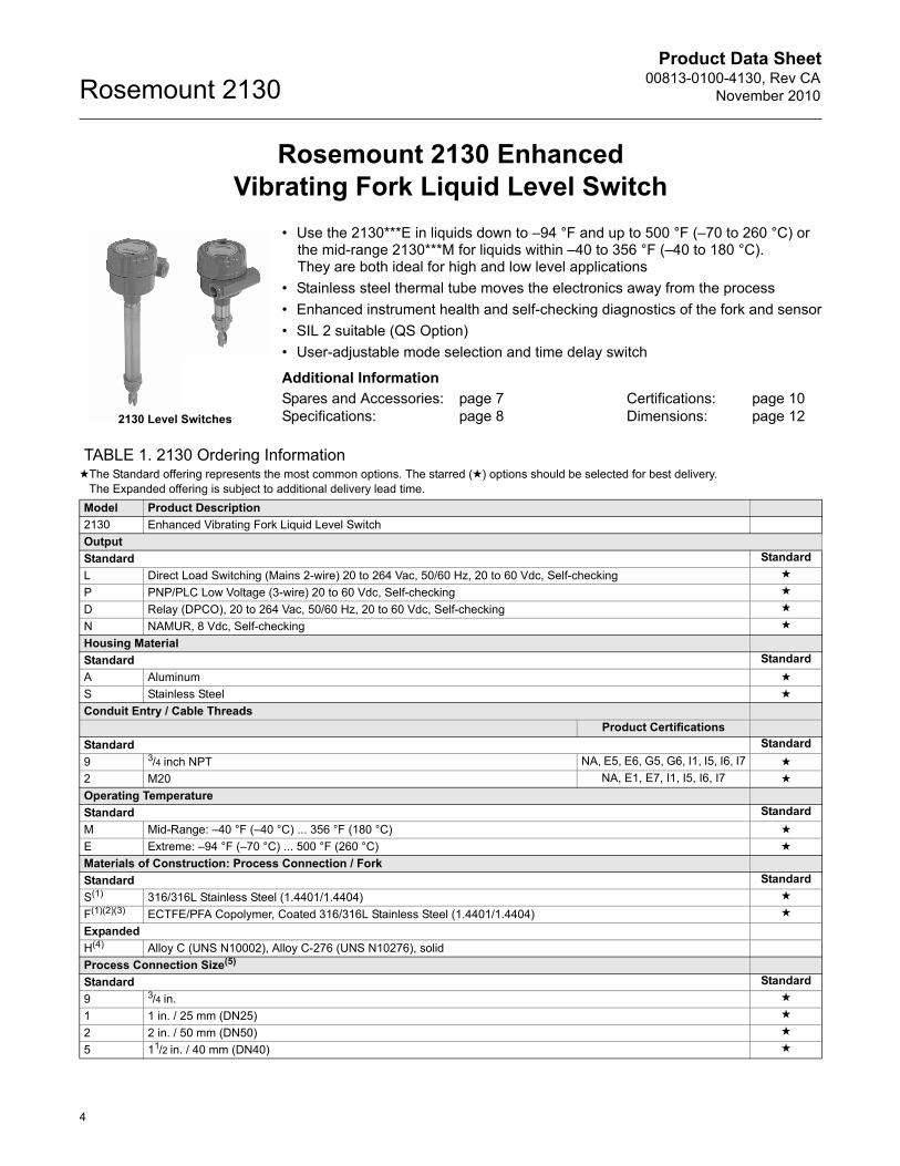
Rosemount 2130 EnhancedVibrating Fork Liquid Level Switch
• Use the 2130***E in liquids down to –94 °F and up to 500 °F (–70 to 260 °C) orthe mid-range 2130***M for liquids within –40 to 356 °F (–40 to 180 °C).They are both ideal for high and low level applications
• Stainless steel thermal tube moves the electronics away from the process
• Enhanced instrument health and self-checking diagnostics of the fork and sensor
• SIL 2 suitable (QS Option)
• User-adjustable mode selection and time delay switch
Additional Information
Spares and Accessories: page 7 Certifications: page 10Specifications: page 8 Dimensions: page 12
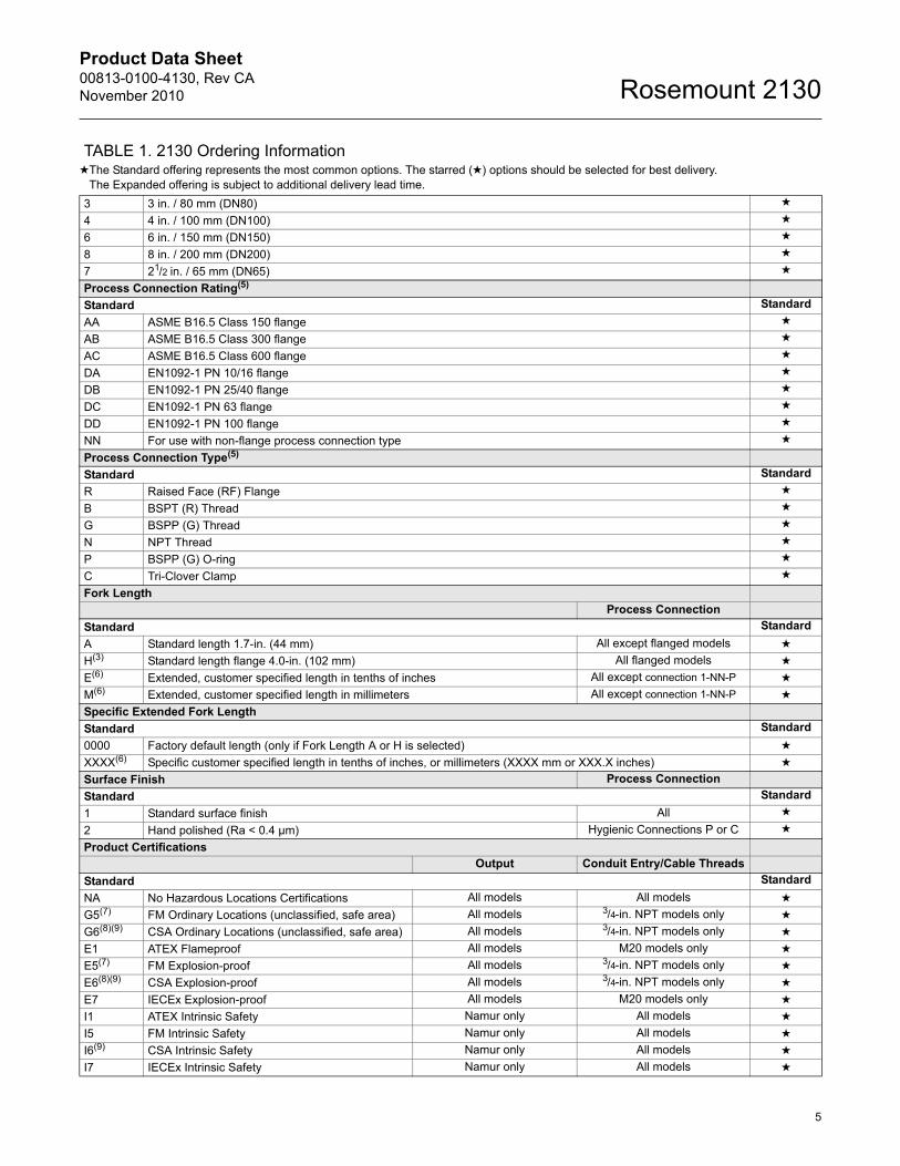
TABLE 1. 2130 Ordering Information★The Standard offering represents the most common options. The starred (★) options should be selected for best delivery.
The Expanded offering is subject to additional delivery lead time.
Model Product Description
2130 Enhanced Vibrating Fork Liquid Level Switch
Output
Standard Standard
L Direct Load Switching (Mains 2-wire) 20 to 264 Vac, 50/60 Hz, 20 to 60 Vdc, Self-checking ★
P PNP/PLC Low Voltage (3-wire) 20 to 60 Vdc, Self-checking ★
D Relay (DPCO), 20 to 264 Vac, 50/60 Hz, 20 to 60 Vdc, Self-checking ★
N NAMUR, 8 Vdc, Self-checking ★
Housing Material
Standard Standard
A Aluminum ★
S Stainless Steel ★
Conduit Entry / Cable ThreadsProduct Certifications
Standard Standard
9 3/4 inch NPT NA, E5, E6, G5, G6, I1, I5, I6, I7 ★
2 M20 NA, E1, E7, I1, I5, I6, I7 ★
Operating Temperature
Standard Standard
M Mid-Range: –40 °F (–40 °C) ... 356 °F (180 °C) ★
E Extreme: –94 °F (–70 °C) ... 500 °F (260 °C) ★
Materials of Construction: Process Connection / Fork
Standard Standard
S(1) 316/316L Stainless Steel (1.4401/1.4404) ★
F(1)(2)(3) ECTFE/PFA Copolymer, Coated 316/316L Stainless Steel (1.4401/1.4404) ★
Expanded
H(4) Alloy C (UNS N10002), Alloy C-276 (UNS N10276), solid
Process Connection Size(5)
Standard Standard
9 3/4 in. ★
1 1 in. / 25 mm (DN25) ★
2 2 in. / 50 mm (DN50) ★
5 11/2 in. / 40 mm (DN40) ★
2130 Level Switches
Product Data Sheet00813-0100-4130, Rev CANovember 2010
5
Rosemount 2130
3 3 in. / 80 mm (DN80) ★
4 4 in. / 100 mm (DN100) ★
6 6 in. / 150 mm (DN150) ★
8 8 in. / 200 mm (DN200) ★
7 21/2 in. / 65 mm (DN65) ★
Process Connection Rating(5)
Standard Standard
AA ASME B16.5 Class 150 flange ★
AB ASME B16.5 Class 300 flange ★
AC ASME B16.5 Class 600 flange ★
DA EN1092-1 PN 10/16 flange ★
DB EN1092-1 PN 25/40 flange ★
DC EN1092-1 PN 63 flange ★
DD EN1092-1 PN 100 flange ★
NN For use with non-flange process connection type ★
Process Connection Type(5)
Standard Standard
R Raised Face (RF) Flange ★
B BSPT (R) Thread ★
G BSPP (G) Thread ★
N NPT Thread ★
P BSPP (G) O-ring ★
C Tri-Clover Clamp ★
Fork LengthProcess Connection
Standard Standard
A Standard length 1.7-in. (44 mm) All except flanged models ★
H(3) Standard length flange 4.0-in. (102 mm) All flanged models ★
E(6) Extended, customer specified length in tenths of inches All except connection 1-NN-P ★
M(6) Extended, customer specified length in millimeters All except connection 1-NN-P ★
Specific Extended Fork Length
Standard Standard
0000 Factory default length (only if Fork Length A or H is selected) ★
XXXX(6) Specific customer specified length in tenths of inches, or millimeters (XXXX mm or XXX.X inches) ★
Surface Finish Process Connection
Standard Standard
1 Standard surface finish All ★
2 Hand polished (Ra < 0.4 µm) Hygienic Connections P or C ★
Product CertificationsOutput Conduit Entry/Cable Threads
Standard Standard
NA No Hazardous Locations Certifications All models All models ★
G5(7) FM Ordinary Locations (unclassified, safe area) All models 3/4-in. NPT models only ★
G6(8)(9) CSA Ordinary Locations (unclassified, safe area) All models 3/4-in. NPT models only ★
E1 ATEX Flameproof All models M20 models only ★
E5(7) FM Explosion-proof All models 3/4-in. NPT models only ★
E6(8)(9) CSA Explosion-proof All models 3/4-in. NPT models only ★
E7 IECEx Explosion-proof All models M20 models only ★
I1 ATEX Intrinsic Safety Namur only All models ★
I5 FM Intrinsic Safety Namur only All models ★
I6(9) CSA Intrinsic Safety Namur only All models ★
I7 IECEx Intrinsic Safety Namur only All models ★
TABLE 1. 2130 Ordering Information★The Standard offering represents the most common options. The starred (★) options should be selected for best delivery.
The Expanded offering is subject to additional delivery lead time.
Product Data Sheet00813-0100-4130, Rev CA
November 2010Rosemount 2130
6
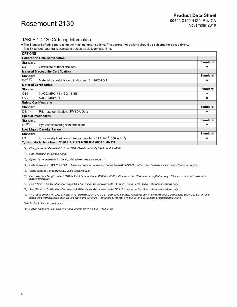
OPTIONS
Calibration Data Certification
Standard Standard
Q4 Certificate of functional test ★
Material Traceability Certification
Standard Standard
Q8(2)(3) Material traceability certification per EN 10204 3.1 ★
Material Certification
Standard Standard
Q15 NACE MR0175 / ISO 15156 ★
Q25 NACE MR0103 ★
Safety Certifications
Standard Standard
QS(10) Prior-use certificate of FMEDA Data ★
Special Procedures
Standard Standard
P1(11) Hydrostatic testing with certificate ★
Low Liquid Density Range
Standard Standard
LD Low density liquids – minimum density is 31.2 lb/ft3 (500 kg/m3) ★
Typical Model Number: 2130 L A 2 E S 9 NN B A 0000 1 NA Q8
(1) Flanges are dual certified 316 and 316L Stainless Steel (1.4401 and 1.4404).
(2) Only available for wetted parts.
(3) Option is not available for hand polished wet side as standard.
(4) Only available for BSPT and NPT threaded process connection codes 9-NN-B, 9-NN-N, 1-NN-B, and 1-NN-N as standard, other upon request.
(5) Other process connections available upon request.
(6) Example Fork Length code E1181 is 118.1 inches. Code M3000 is 3000 millimeters. See “Extended Lengths” on page 8 for minimum and maximum extended lengths.
(7) See “Product Certifications” on page 10. E5 includes G5 requirements. G5 is for use in unclassified, safe area locations only.
(8) See “Product Certifications” on page 10. E6 includes G6 requirements. G6 is for use in unclassified, safe area locations only.
(9) The requirements of CRN are met when a Rosemount 2130 CSA approved vibrating fork level switch (with Product Certifications code G6, E6, or I6) is configured with stainless steel wetted parts and either NPT threaded or ASME B16.5 2-in. to 8-in. flanged process connections.
(10) Available for all output types.
(11) Option limited to units with extended lengths up to 59.1 in. (1500 mm).
TABLE 1. 2130 Ordering Information★The Standard offering represents the most common options. The starred (★) options should be selected for best delivery.
The Expanded offering is subject to additional delivery lead time.
Product Data Sheet00813-0100-4130, Rev CANovember 2010
7
Rosemount 2130
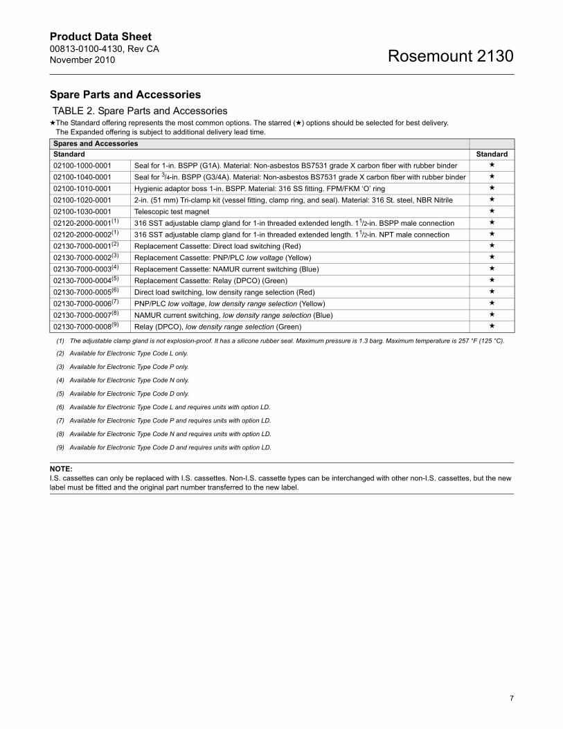
Spare Parts and Accessories
NOTE:I.S. cassettes can only be replaced with I.S. cassettes. Non-I.S. cassette types can be interchanged with other non-I.S. cassettes, but the new label must be fitted and the original part number transferred to the new label.
TABLE 2. Spare Parts and Accessories★The Standard offering represents the most common options. The starred (★) options should be selected for best delivery.
The Expanded offering is subject to additional delivery lead time.
Spares and Accessories
Standard Standard
02100-1000-0001 Seal for 1-in. BSPP (G1A). Material: Non-asbestos BS7531 grade X carbon fiber with rubber binder ★
02100-1040-0001 Seal for 3/4-in. BSPP (G3/4A). Material: Non-asbestos BS7531 grade X carbon fiber with rubber binder ★
02100-1010-0001 Hygienic adaptor boss 1-in. BSPP. Material: 316 SS fitting. FPM/FKM ‘O’ ring ★
02100-1020-0001 2-in. (51 mm) Tri-clamp kit (vessel fitting, clamp ring, and seal). Material: 316 St. steel, NBR Nitrile ★
02100-1030-0001 Telescopic test magnet ★
02120-2000-0001(1) 316 SST adjustable clamp gland for 1-in threaded extended length. 11/2-in. BSPP male connection ★
02120-2000-0002(1) 316 SST adjustable clamp gland for 1-in threaded extended length. 11/2-in. NPT male connection ★
02130-7000-0001(2) Replacement Cassette: Direct load switching (Red) ★
02130-7000-0002(3) Replacement Cassette: PNP/PLC low voltage (Yellow) ★
02130-7000-0003(4) Replacement Cassette: NAMUR current switching (Blue) ★
02130-7000-0004(5) Replacement Cassette: Relay (DPCO) (Green) ★
02130-7000-0005(6) Direct load switching, low density range selection (Red) ★
02130-7000-0006(7) PNP/PLC low voltage, low density range selection (Yellow) ★
02130-7000-0007(8) NAMUR current switching, low density range selection (Blue) ★
02130-7000-0008(9) Relay (DPCO), low density range selection (Green) ★
(1) The adjustable clamp gland is not explosion-proof. It has a silicone rubber seal. Maximum pressure is 1.3 barg. Maximum temperature is 257 °F (125 °C).
(2) Available for Electronic Type Code L only.
(3) Available for Electronic Type Code P only.
(4) Available for Electronic Type Code N only.
(5) Available for Electronic Type Code D only.
(6) Available for Electronic Type Code L and requires units with option LD.
(7) Available for Electronic Type Code P and requires units with option LD.
(8) Available for Electronic Type Code N and requires units with option LD.
(9) Available for Electronic Type Code D and requires units with option LD.
Product Data Sheet00813-0100-4130, Rev CA
November 2010Rosemount 2130
8
Specifications
Physical
ProductRosemount 2130 Enhanced Vibrating Fork Liquid Level Switch
Measuring PrincipleVibrating Fork
ApplicationsMost liquids including coating liquids, aerated liquids, and slurries
Mechanical
Housing/Enclosure Non-rotational housing/enclosure
ConnectionsSee Table 1 on page 4 for Conduit Entry/Cable Thread and Process Connection options
Extended LengthsThe maximum extended length is 118.1 in. (3000 mm) except for a hand-polished 2130 that is limited to 39.4 in. (1000 mm), and the ECTFE/PFE copolymer coated flange 2130 that is limited to59.1 in. (1500 mm)
Process Material316/316L Stainless Steel, ECTFE/PFA copolymer coated 316/316L Stainless Steel, orsolid Alloy C (UNS N10002) and Alloy C-276 (UNS N10276)
Hand-polished to better than 0.4 m option available for hygienic connections
Gasket material for 3/4-in. and 1-in. BSPP (G) is non-asbestos BS7531 Grade X carbon fiber with rubber binder
Dimensional DrawingsSee “Dimensional Drawings” on page 12
Performance
Hysteresis (Water)0.1 in. (2.5 mm)
Switching Point (Water)0.5 in. (13 mm) from tip of fork (if vertical installation) or from edge of fork (if horizontal installation) – this will vary with different liquid densities
Functional
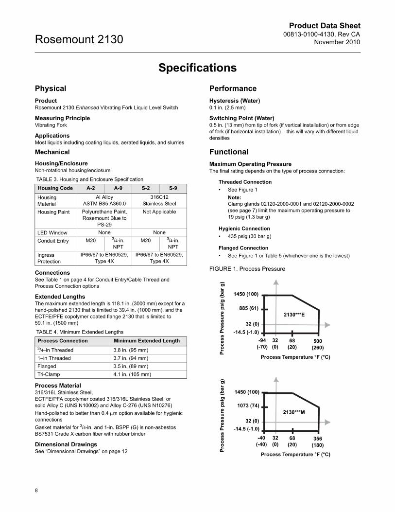
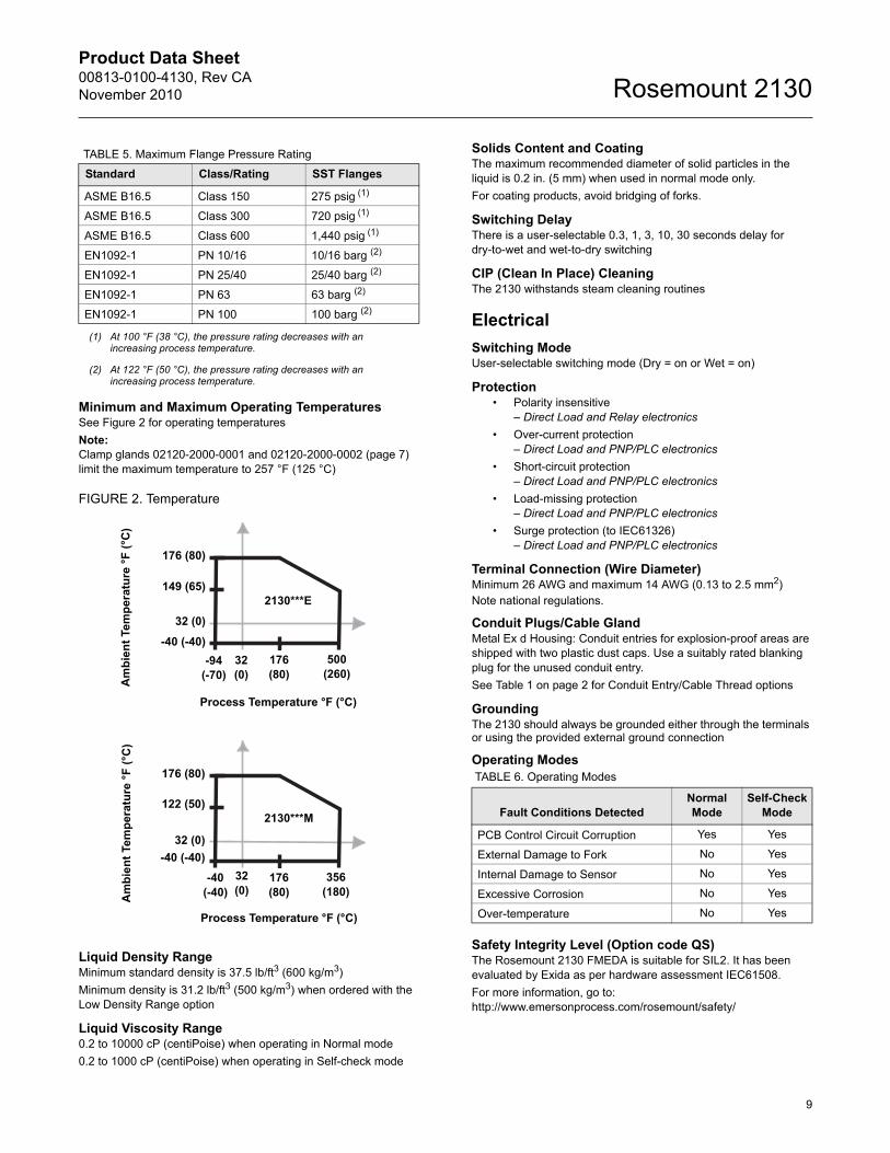
Maximum Operating PressureThe final rating depends on the type of process connection:
Threaded Connection
• See Figure 1
Note:Clamp glands 02120-2000-0001 and 02120-2000-0002 (see page 7) limit the maximum operating pressure to 19 psig (1.3 bar g)
Hygienic Connection
• 435 psig (30 bar g)
Flanged Connection
• See Figure 1 or Table 5 (whichever one is the lowest)
FIGURE 1. Process Pressure
TABLE 3. Housing and Enclosure Specification
Housing Code A-2 A-9 S-2 S-9
Housing Material
Al Alloy ASTM B85 A360.0
316C12 Stainless Steel
Housing Paint Polyurethane Paint, Rosemount Blue to
PS-29
Not Applicable
LED Window None None
Conduit Entry M20 3/4-in. NPT
M20 3/4-in. NPT
Ingress Protection
IP66/67 to EN60529, Type 4X
IP66/67 to EN60529, Type 4X
TABLE 4. Minimum Extended Lengths
Process Connection Minimum Extended Length
3/4–in Threaded 3.8 in. (95 mm)
1–in Threaded 3.7 in. (94 mm)
Flanged 3.5 in. (89 mm)
Tri-Clamp 4.1 in. (105 mm)
1450 (100)
885 (61)
-14.5 (-1.0)
-94 (-70)
68 (20)
500 (260)
Process Temperature °F (°C)
Pro
cess
Pre
ssu
re p
sig
(b
ar g
)
32 (0)
32 (0)
2130***E
1450 (100)
1073 (74)
-14.5 (-1.0)
-40 (-40)
68 (20)
356 (180)
Process Temperature °F (°C)
Pro
ces
s P
res
sure
psi
g (
bar
g)
32 (0)
32 (0)
2130***M
Product Data Sheet00813-0100-4130, Rev CANovember 2010
9
Rosemount 2130
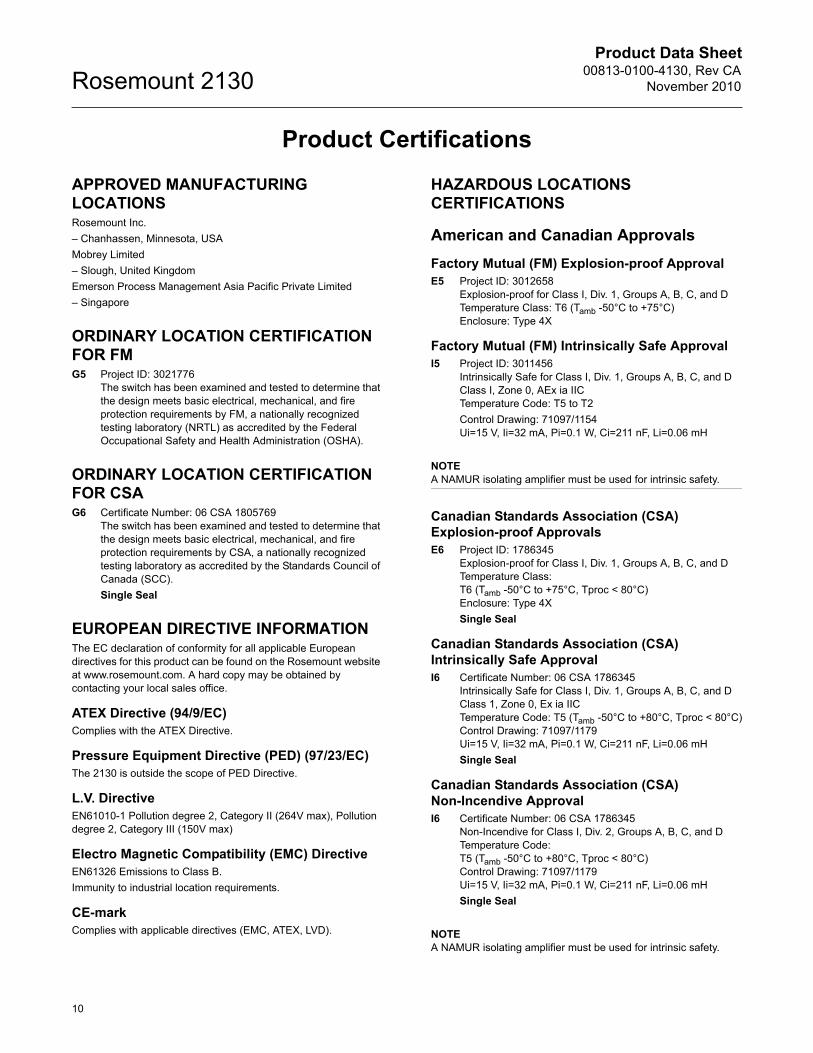
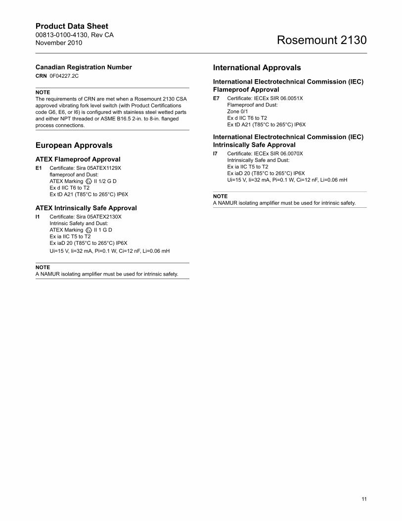
Minimum and Maximum Operating TemperaturesSee Figure 2 for operating temperatures
Note:Clamp glands 02120-2000-0001 and 02120-2000-0002 (page 7) limit the maximum temperature to 257 °F (125 °C)
FIGURE 2. Temperature
Liquid Density RangeMinimum standard density is 37.5 lb/ft3 (600 kg/m3)
Minimum density is 31.2 lb/ft3 (500 kg/m3) when ordered with the Low Density Range option
Liquid Viscosity Range0.2 to 10000 cP (centiPoise) when operating in Normal mode
0.2 to 1000 cP (centiPoise) when operating in Self-check mode
Solids Content and CoatingThe maximum recommended diameter of solid particles in the liquid is 0.2 in. (5 mm) when used in normal mode only.
For coating products, avoid bridging of forks.
Switching DelayThere is a user-selectable 0.3, 1, 3, 10, 30 seconds delay for dry-to-wet and wet-to-dry switching
CIP (Clean In Place) CleaningThe 2130 withstands steam cleaning routines
Electrical
Switching ModeUser-selectable switching mode (Dry = on or Wet = on)
Protection• Polarity insensitive
– Direct Load and Relay electronics
• Over-current protection– Direct Load and PNP/PLC electronics
• Short-circuit protection– Direct Load and PNP/PLC electronics
• Load-missing protection– Direct Load and PNP/PLC electronics
• Surge protection (to IEC61326)– Direct Load and PNP/PLC electronics
Terminal Connection (Wire Diameter)Minimum 26 AWG and maximum 14 AWG (0.13 to 2.5 mm2)Note national regulations.
Conduit Plugs/Cable GlandMetal Ex d Housing: Conduit entries for explosion-proof areas are shipped with two plastic dust caps. Use a suitably rated blanking plug for the unused conduit entry.
See Table 1 on page 2 for Conduit Entry/Cable Thread options
GroundingThe 2130 should always be grounded either through the terminals or using the provided external ground connection
Operating Modes
Safety Integrity Level (Option code QS)The Rosemount 2130 FMEDA is suitable for SIL2. It has been evaluated by Exida as per hardware assessment IEC61508.
For more information, go to: http://www.emersonprocess.com/rosemount/safety/
TABLE 5. Maximum Flange Pressure Rating
Standard Class/Rating SST Flanges
ASME B16.5 Class 150 275 psig (1)
(1) At 100 °F (38 °C), the pressure rating decreases with an increasing process temperature.
ASME B16.5 Class 300 720 psig (1)
ASME B16.5 Class 600 1,440 psig (1)
EN1092-1 PN 10/16 10/16 barg (2)
(2) At 122 °F (50 °C), the pressure rating decreases with an increasing process temperature.
EN1092-1 PN 25/40 25/40 barg (2)
EN1092-1 PN 63 63 barg (2)
EN1092-1 PN 100 100 barg (2)
176 (80)
176 (80)
-40 (-40)
-94 (-70)
500 (260)
Process Temperature °F (°C)
Am
bie
nt
Tem
per
atu
re °
F (
°C)
149 (65)
32 (0)
32 (0)
2130***E
176 (80)
176 (80)
-40 (-40)
-40 (-40)
356 (180)
Process Temperature °F (°C)
Am
bie
nt
Tem
per
atu
re °
F (
°C)
122 (50)
32 (0)
32 (0)
2130***M
TABLE 6. Operating Modes
Fault Conditions DetectedNormal Mode
Self-Check Mode
PCB Control Circuit Corruption Yes Yes
External Damage to Fork No Yes
Internal Damage to Sensor No Yes
Excessive Corrosion No Yes
Over-temperature No Yes
Product Data Sheet00813-0100-4130, Rev CA
November 2010Rosemount 2130
10
Product Certifications
APPROVED MANUFACTURING LOCATIONSRosemount Inc.
– Chanhassen, Minnesota, USA
Mobrey Limited
– Slough, United Kingdom
Emerson Process Management Asia Pacific Private Limited
– Singapore
ORDINARY LOCATION CERTIFICATION FOR FMG5 Project ID: 3021776
The switch has been examined and tested to determine that the design meets basic electrical, mechanical, and fire protection requirements by FM, a nationally recognized testing laboratory (NRTL) as accredited by the Federal Occupational Safety and Health Administration (OSHA).
ORDINARY LOCATION CERTIFICATION FOR CSAG6 Certificate Number: 06 CSA 1805769
The switch has been examined and tested to determine that the design meets basic electrical, mechanical, and fire protection requirements by CSA, a nationally recognized testing laboratory as accredited by the Standards Council of Canada (SCC).
Single Seal
EUROPEAN DIRECTIVE INFORMATIONThe EC declaration of conformity for all applicable European directives for this product can be found on the Rosemount website at www.rosemount.com. A hard copy may be obtained by contacting your local sales office.
ATEX Directive (94/9/EC)Complies with the ATEX Directive.
Pressure Equipment Directive (PED) (97/23/EC)The 2130 is outside the scope of PED Directive.
L.V. DirectiveEN61010-1 Pollution degree 2, Category II (264V max), Pollution degree 2, Category III (150V max)
Electro Magnetic Compatibility (EMC) DirectiveEN61326 Emissions to Class B.
Immunity to industrial location requirements.
CE-markComplies with applicable directives (EMC, ATEX, LVD).
HAZARDOUS LOCATIONS CERTIFICATIONS
American and Canadian Approvals
Factory Mutual (FM) Explosion-proof ApprovalE5 Project ID: 3012658
Explosion-proof for Class I, Div. 1, Groups A, B, C, and DTemperature Class: T6 (Tamb -50°C to +75°C)Enclosure: Type 4X
Factory Mutual (FM) Intrinsically Safe ApprovalI5 Project ID: 3011456
Intrinsically Safe for Class I, Div. 1, Groups A, B, C, and DClass I, Zone 0, AEx ia IICTemperature Code: T5 to T2
Control Drawing: 71097/1154Ui=15 V, Ii=32 mA, Pi=0.1 W, Ci=211 nF, Li=0.06 mH
NOTEA NAMUR isolating amplifier must be used for intrinsic safety.
Canadian Standards Association (CSA)Explosion-proof ApprovalsE6 Project ID: 1786345
Explosion-proof for Class I, Div. 1, Groups A, B, C, and DTemperature Class:T6 (Tamb -50°C to +75°C, Tproc < 80°C)Enclosure: Type 4X
Single Seal
Canadian Standards Association (CSA)Intrinsically Safe ApprovalI6 Certificate Number: 06 CSA 1786345
Intrinsically Safe for Class I, Div. 1, Groups A, B, C, and DClass 1, Zone 0, Ex ia IICTemperature Code: T5 (Tamb -50°C to +80°C, Tproc < 80°C)Control Drawing: 71097/1179Ui=15 V, Ii=32 mA, Pi=0.1 W, Ci=211 nF, Li=0.06 mH
Single Seal
Canadian Standards Association (CSA)Non-Incendive ApprovalI6 Certificate Number: 06 CSA 1786345
Non-Incendive for Class I, Div. 2, Groups A, B, C, and DTemperature Code: T5 (Tamb -50°C to +80°C, Tproc < 80°C)Control Drawing: 71097/1179Ui=15 V, Ii=32 mA, Pi=0.1 W, Ci=211 nF, Li=0.06 mH
Single Seal
NOTEA NAMUR isolating amplifier must be used for intrinsic safety.
Product Data Sheet00813-0100-4130, Rev CANovember 2010
11
Rosemount 2130
Canadian Registration NumberCRN 0F04227.2C
NOTEThe requirements of CRN are met when a Rosemount 2130 CSA approved vibrating fork level switch (with Product Certifications code G6, E6, or I6) is configured with stainless steel wetted parts and either NPT threaded or ASME B16.5 2-in. to 8-in. flanged process connections.
European Approvals
ATEX Flameproof ApprovalE1 Certificate: Sira 05ATEX1129X
flameproof and Dust: ATEX Marking II 1/2 G DEx d IIC T6 to T2Ex tD A21 (T85°C to 265°C) IP6X
ATEX Intrinsically Safe ApprovalI1 Certificate: Sira 05ATEX2130X
Intrinsic Safety and Dust: ATEX Marking II 1 G DEx ia IIC T5 to T2Ex iaD 20 (T85°C to 265°C) IP6X
Ui=15 V, Ii=32 mA, Pi=0.1 W, Ci=12 nF, Li=0.06 mH
NOTEA NAMUR isolating amplifier must be used for intrinsic safety.
International Approvals
International Electrotechnical Commission (IEC) Flameproof ApprovalE7 Certificate: IECEx SIR 06.0051X
Flameproof and Dust:Zone 0/1Ex d IIC T6 to T2Ex tD A21 (T85°C to 265°C) IP6X
International Electrotechnical Commission (IEC) Intrinsically Safe ApprovalI7 Certificate: IECEx SIR 06.0070X
Intrinsically Safe and Dust: Ex ia IIC T5 to T2Ex iaD 20 (T85°C to 265°C) IP6XUi=15 V, Ii=32 mA, Pi=0.1 W, Ci=12 nF, Li=0.06 mH
NOTEA NAMUR isolating amplifier must be used for intrinsic safety.
Product Data Sheet00813-0100-4130, Rev CA
November 2010Rosemount 2130
12
Dimensional Drawings
2130 Thread Mounting (Standard Length) . . . . . . . . . . . . . . . . . . . . . . . . . . . . . . . . . . . . page 12
2130 Thread Mounting (Extended Length) . . . . . . . . . . . . . . . . . . . . . . . . . . . . . . . . . . . . page 13
2130 Flange Mounting (Standard Length) . . . . . . . . . . . . . . . . . . . . . . . . . . . . . . . . . . . . page 14
2130 Flange Mounting (Extended Length) . . . . . . . . . . . . . . . . . . . . . . . . . . . . . . . . . . . . page 15
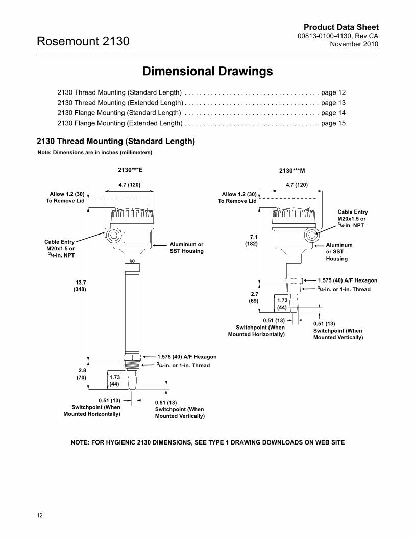
2130 Thread Mounting (Standard Length)
Aluminum or SST Housing
0.51 (13)Switchpoint (When
Mounted Horizontally)
0.51 (13)Switchpoint (When Mounted Vertically)
13.7(348)
4.7 (120)
1.73(44)
Cable EntryM20x1.5 or3/4-in. NPT
Note: Dimensions are in inches (millimeters)
2.8(70)
Allow 1.2 (30)To Remove Lid
2130***E 2130***M
Allow 1.2 (30)To Remove Lid
4.7 (120)
7.1(182)
2.7(69) 1.73
(44)
0.51 (13)Switchpoint (When Mounted Vertically)
0.51 (13)Switchpoint (When
Mounted Horizontally)
Aluminumor SSTHousing
Cable EntryM20x1.5 or3/4-in. NPT
1.575 (40) A/F Hexagon3/4-in. or 1-in. Thread
NOTE: FOR HYGIENIC 2130 DIMENSIONS, SEE TYPE 1 DRAWING DOWNLOADS ON WEB SITE
1.575 (40) A/F Hexagon3/4-in. or 1-in. Thread
Product Data Sheet00813-0100-4130, Rev CANovember 2010
13
Rosemount 2130
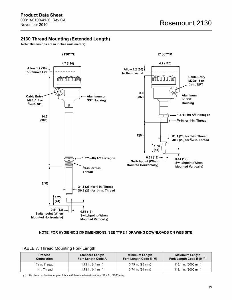
2130 Thread Mounting (Extended Length)
TABLE 7. Thread Mounting Fork Length
Aluminum or SST Housing
3/4-in. or 1-in.Thread
E(M)
1.73(44)
Cable EntryM20x1.5 or3/4-in. NPT
Note: Dimensions are in inches (millimeters)
0.51 (13)Switchpoint (When
Mounted Horizontally)
0.51 (13)Switchpoint (When Mounted Vertically)
14.5(368)
4.7 (120)
Allow 1.2 (30)To Remove Lid
Ø1.1 (28) for 1-in. ThreadØ0.9 (23) for 3/4-in. Thread
2130***E
4.7 (120)
Aluminumor SSTHousing
Cable EntryM20x1.5 or3/4-in. NPT
Allow 1.2 (30)To Remove Lid
8.0(202)
1.575 (40) A/F Hexagon
3/4-in. or 1-in. Thread
Ø1.1 (28) for 1-in. ThreadØ0.9 (23) for 3/4-in. Thread
0.51 (13)Switchpoint (When Mounted Vertically)
0.51 (13)Switchpoint (When
Mounted Horizontally)
1.73(44)
2130***M
E(M)
1.575 (40) A/F Hexagon
NOTE: FOR HYGIENIC 2130 DIMENSIONS, SEE TYPE 1 DRAWING DOWNLOADS ON WEB SITE
ProcessConnection
Standard LengthFork Length Code A
Minimum LengthFork Length Code E (M)
Maximum Length Fork Length Code E (M)(1)
3/4-in. Thread 1.73 in. (44 mm) 3.75 in. (95 mm) 118.1 in. (3000 mm)
1-in. Thread 1.73 in. (44 mm) 3.74 in. (94 mm) 118.1 in. (3000 mm)
(1) Maximum extended length of fork with hand-polished option is 39.4 in. (1000 mm).
Product Data Sheet00813-0100-4130, Rev CA
November 2010Rosemount 2130
14
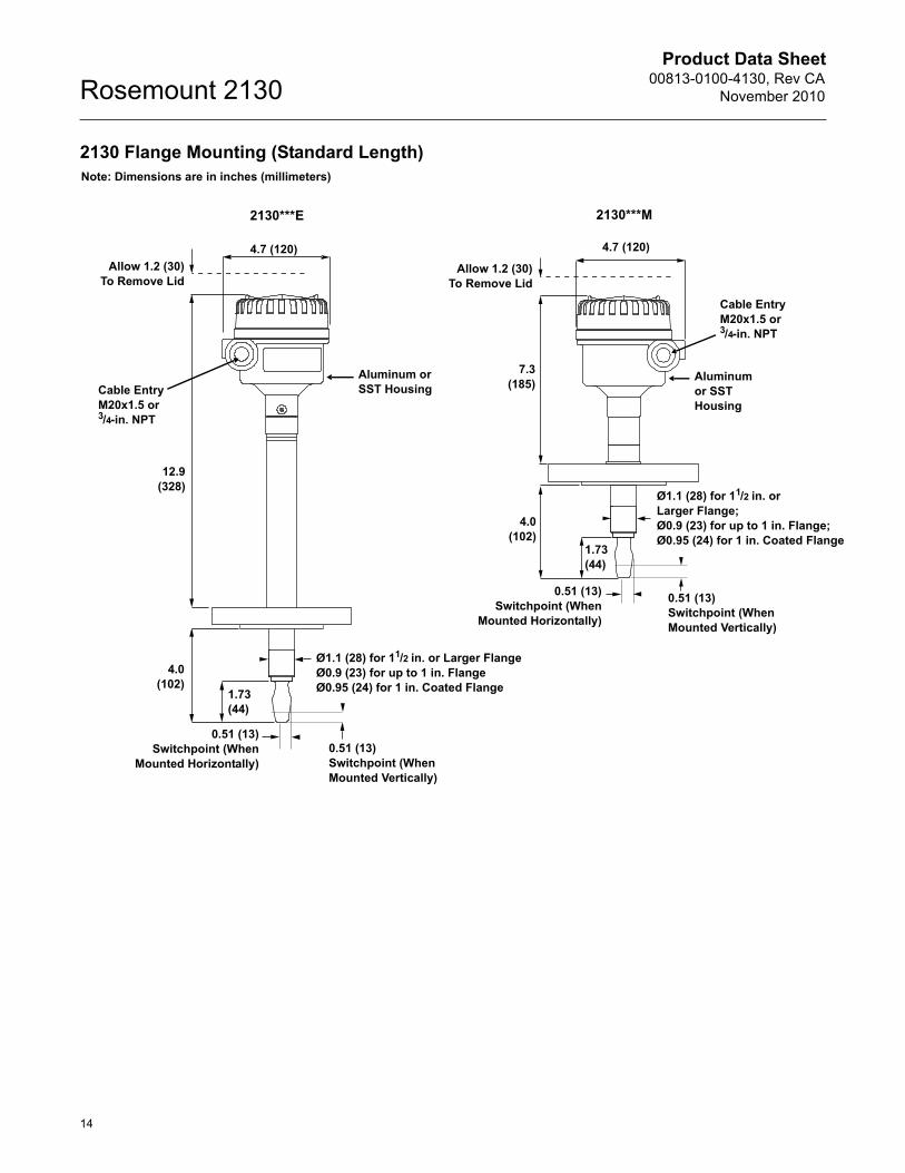
2130 Flange Mounting (Standard Length)Note: Dimensions are in inches (millimeters)
Aluminum or SST Housing
12.9(328)
Cable EntryM20x1.5 or3/4-in. NPT
1.73(44)
4.0(102)
0.51 (13)Switchpoint (When
Mounted Horizontally)
Ø1.1 (28) for 11/2 in. or Larger FlangeØ0.9 (23) for up to 1 in. FlangeØ0.95 (24) for 1 in. Coated Flange
0.51 (13)Switchpoint (When Mounted Vertically)
4.7 (120)
Allow 1.2 (30)To Remove Lid
2130***E 2130***M
4.7 (120)
Aluminumor SSTHousing
Cable EntryM20x1.5 or3/4-in. NPT
Allow 1.2 (30)To Remove Lid
7.3(185)
4.0(102)
1.73(44)
0.51 (13)Switchpoint (When
Mounted Horizontally)
0.51 (13)Switchpoint (When Mounted Vertically)
Ø1.1 (28) for 11/2 in. orLarger Flange;Ø0.9 (23) for up to 1 in. Flange;Ø0.95 (24) for 1 in. Coated Flange
Product Data Sheet00813-0100-4130, Rev CANovember 2010
15
Rosemount 2130
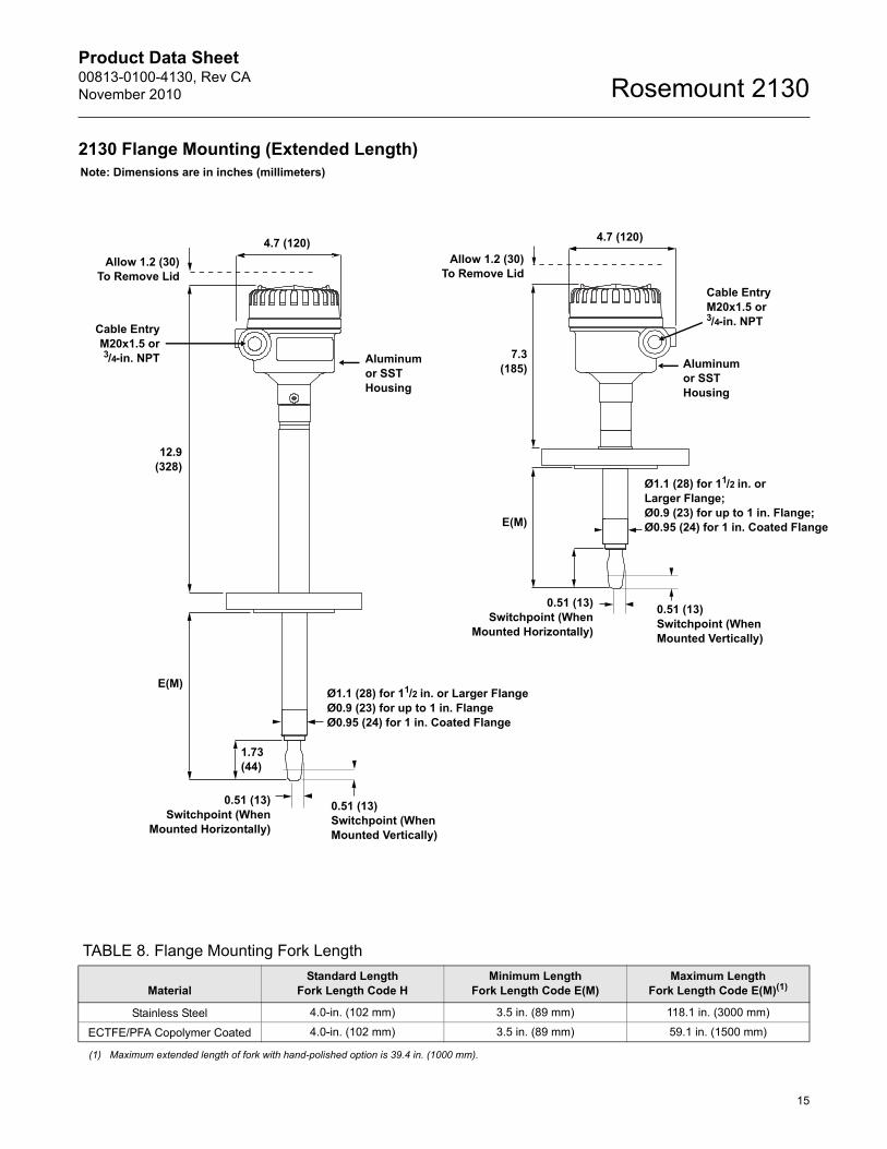
2130 Flange Mounting (Extended Length)
TABLE 8. Flange Mounting Fork Length
Note: Dimensions are in inches (millimeters)
Aluminumor SSTHousing
Cable EntryM20x1.5 or3/4-in. NPT
1.73(44)
12.9(328)
E(M)
0.51 (13)Switchpoint (When
Mounted Horizontally)
Ø1.1 (28) for 11/2 in. or Larger FlangeØ0.9 (23) for up to 1 in. FlangeØ0.95 (24) for 1 in. Coated Flange
0.51 (13)Switchpoint (When Mounted Vertically)
4.7 (120)
Allow 1.2 (30)To Remove Lid
4.7 (120)
Aluminumor SSTHousing
Cable EntryM20x1.5 or3/4-in. NPT
Allow 1.2 (30)To Remove Lid
0.51 (13)Switchpoint (When
Mounted Horizontally)
0.51 (13)Switchpoint (When Mounted Vertically)
Ø1.1 (28) for 11/2 in. orLarger Flange;Ø0.9 (23) for up to 1 in. Flange;Ø0.95 (24) for 1 in. Coated FlangeE(M)
7.3(185)
MaterialStandard Length
Fork Length Code HMinimum Length
Fork Length Code E(M)Maximum Length
Fork Length Code E(M)(1)
Stainless Steel 4.0-in. (102 mm) 3.5 in. (89 mm) 118.1 in. (3000 mm)
ECTFE/PFA Copolymer Coated 4.0-in. (102 mm) 3.5 in. (89 mm) 59.1 in. (1500 mm)
(1) Maximum extended length of fork with hand-polished option is 39.4 in. (1000 mm).
Product Data Sheet00813-0100-4130, Rev CA
November 2010Rosemount 2130
The Emerson logo is a trademark and service mark of Emerson Electric Co.Rosemount and the Rosemount logotype are registered trademarks of Rosemount Inc.All other marks are the property of their respective owners.Standard Terms and Conditions of Sale can be found at www.rosemount.com\terms_of_sale
00813-0100-4130 Rev CA 11/10
© 2010 Rosemount, Inc. All rights reserved.
Emerson Process Management Rosemount Division8200 Market BoulevardChanhassen, MN 55317 USAT (U.S.) 1-800-999-9307T (International) (952) 906-8888F (952) 949-7001www.rosemount.com
Emerson Process ManagementBleigistrasse 23P.O. Box 1046CH 6341 BaarSwitzerlandT +41 (0) 41 768 6111F +41 (0) 41 768 6300
Emerson Process ManagementAsia Pacific Pte Ltd1 Pandan CrescentSingapore 128461T +65 6777 8211F +65 6777 0947Service Support Hotline: +65 6770 8711Email: [email protected]
Emerson FZEP.O. Box 17033Jebel Ali Free ZoneDubai UAET +971 4 883 5235F +971 4 883 5312
Rosemount Level Solutions
Emerson provides a complete range of Rosemount products for level measurement applications.
Pressure – Level or Interface Measurement
Emerson has a complete line of Rosemount pressure transmitters and remote seals for measuring level or interfaces in liquid applications. Optimize performance with direct mount, Tuned Seal systems:
• Rosemount 3051S_L, 3051L, and 1151LT Liquid Level Transmitters
• Rosemount 1199 Remote Diaphragm Seals with direct mount or capillary connections
Vibrating Fork Switches – Point Level Detection
The Rosemount 2100 Series is developed for reliable point level detection of liquids and consists of:
• Rosemount 2110 Compact Vibrating ForkLiquid Level Switch
• Rosemount 2120 Full-featured Vibrating ForkLiquid Level Switch
• Rosemount 2130 Extreme Temperature Vibrating ForkLiquid Level Switch
• Rosemount 2160 Wireless Vibrating ForkLiquid Level Switch
Guided Wave Radar – Level and Interface Measurement
Multivariable, loop-powered Guided Wave Radar transmitters with a wide range of probe styles to fit different liquids and solids applications. The product line consists of:
• Rosemount 3300 Series – Versatile and easy-to-use transmitter with proven reliability
• Rosemount 5300 Series – Accurate, high performance transmitter with FOUNDATION™ fieldbus support
Non-contacting Radar – Level Measurement
The Rosemount non-contacting radar family consists of:
• Rosemount 5400 Series Transmitters – Loop-poweredtransmitter with a wide range of antennas, for liquid level measurement in most applications and process conditions
• Rosemount 5600 Series Transmitters – 4-wire loop-powered transmitter giving maximum sensitivity and performance for solids, challenging reactors, rapid level changes and excessive process conditions.
Non-contacting Ultrasonic – Level Measurement
The Rosemount 3100 Series ultrasonic level transmitters provide continuous non-contacting level measurement of liquids. The range consists of:
• Rosemount 3101 for simple continuous level measurement
• Rosemount 3102 for continuous measurement with two integral relays for local control functionality
• Rosemount 3105 Intrinsically safe certified version for hazardous areas